- - FEASIBILITY STUDY REPORT - OPERABLE UNIT I - - LOCKHEED MARTIN TACTICAL DEFENSE SYSTEMS DIVISION (Former Unisys Corp. Site) - - Great Neck, New York NYSDEC Site NO.130045 - - Prepared for: New York State - Department of Environmental Conservation - - On behalf of: - Lockheed Martin Tactical Defense Systems Division of Lockheed Martin Tactical Systems, Inc. - - JANUARY 1997 Prepared by: - Holzmacher, McLendon & Murrell, P.C. - - Vice President -
Transcript
-- FEASIBILITY STUDY REPORT
- OPERABLE UNIT I
-- LOCKHEED MARTIN TACTICAL DEFENSE SYSTEMS DIVISION
(Former Unisys Corp. Site)
-- Great Neck, New York
NYSDEC Site NO.130045 --
Prepared for: New York State-
Department of Environmental Conservation -- On behalf of:
- Lockheed Martin Tactical Defense Systems Division of Lockheed Martin Tactical Systems, Inc.
-- JANUARY 1997
Prepared by: -Holzmacher, McLendon & Murrell, P.C. -~9-- Vice President
-
--
Il~GROUP
FEASffiILITY STUDY REPORT
OPERABLE UNIT I - Lockheed Martin Tactical Defense Systems Division of
Lockheed Martin Tactical Systems, Inc.
(Former Unisys Corp. Site) -Great Neck, New York
NYSDEC Site ID #130045• January 1997
Table of Contents
• Page No.
1.0 Introduction I
2.0 Background Information 2• 2.1 Site Description 2
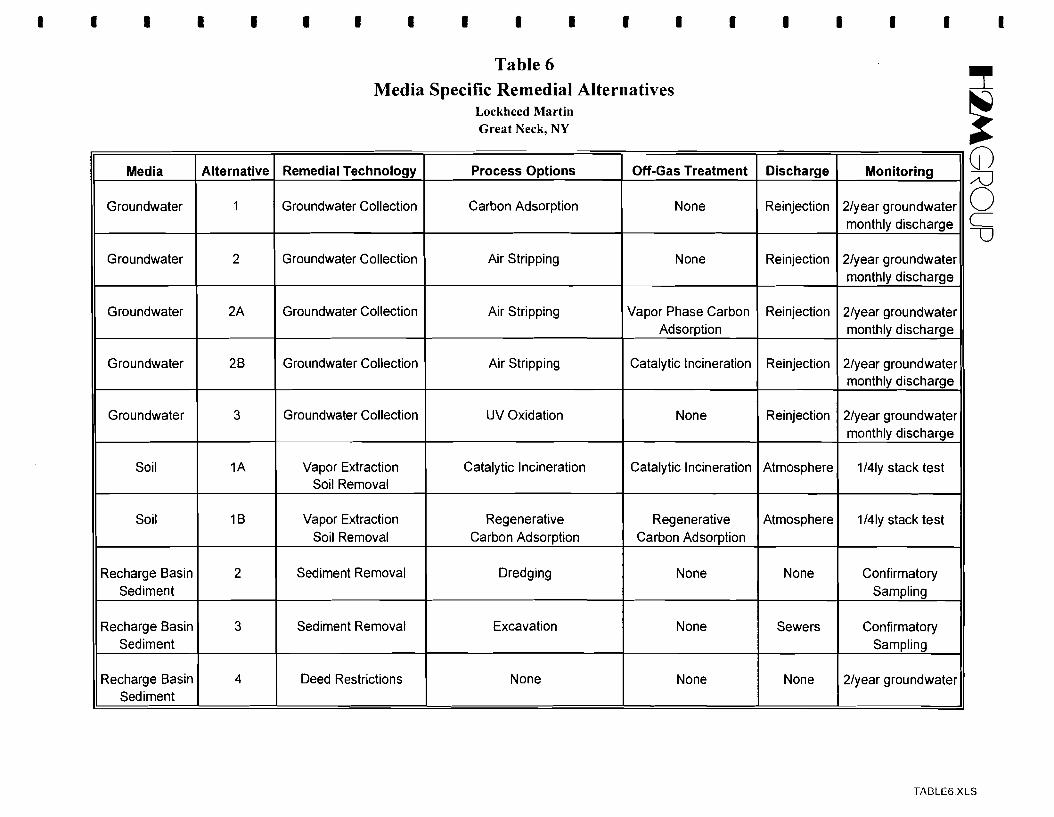
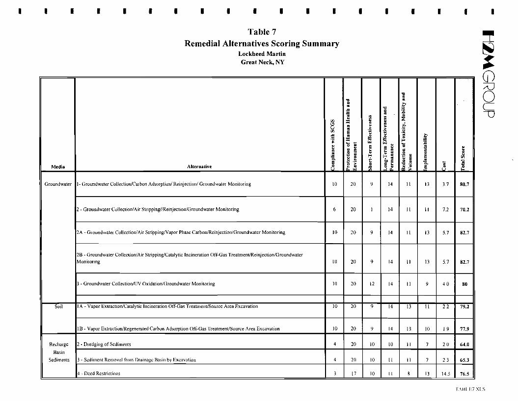
Table 6 Media Specific Remedial Alternatives - Table 7 Remedial Alternatives Scoring Summary
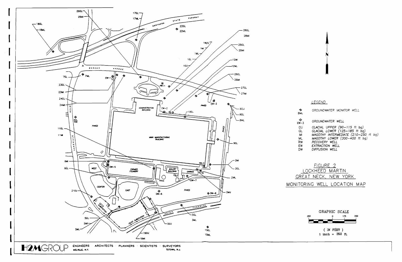
List of Figures -Figure 1 Site Location Map
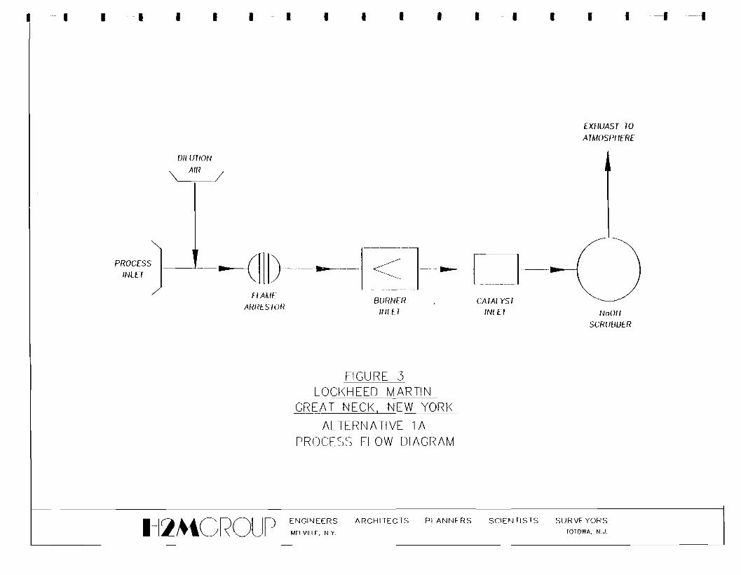
Figure 2 Monitor Well Location Map- Figure 3 Alternative lA - Process Flow Diagram
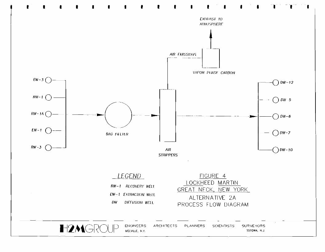
Figure 4 Alternative 2A - Process Flow Diagram-III-
- ti:lMGROLIP
------
Appendix A
Appendix B
Appendix C
Appendix D
Appendix E
Appendix F
------------
Table of Contents
(Continued)
List of Appendices
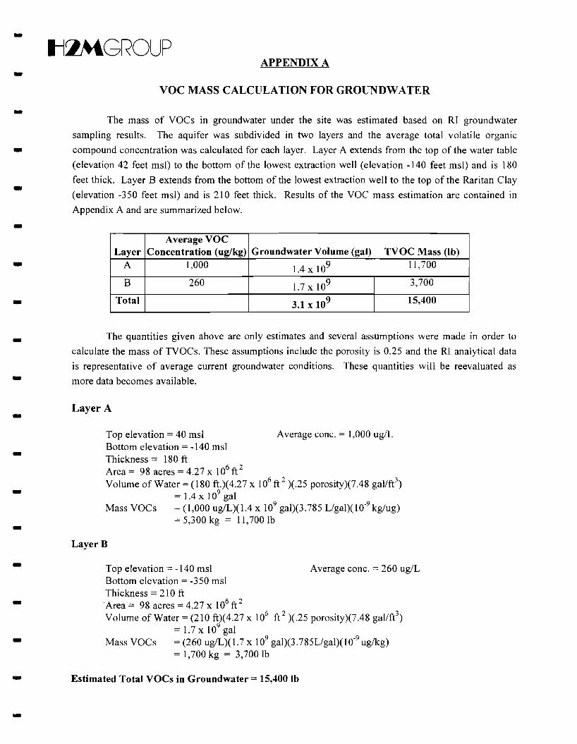
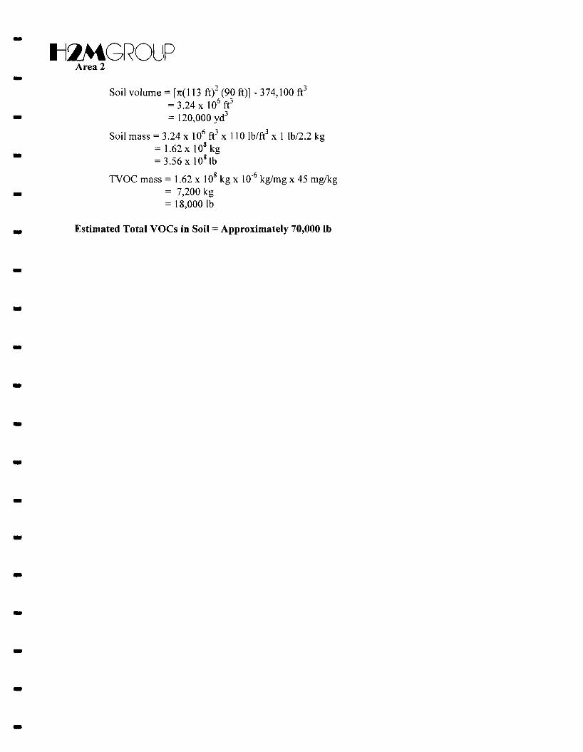
VOC Mass Calculation for Soil and Groundwater
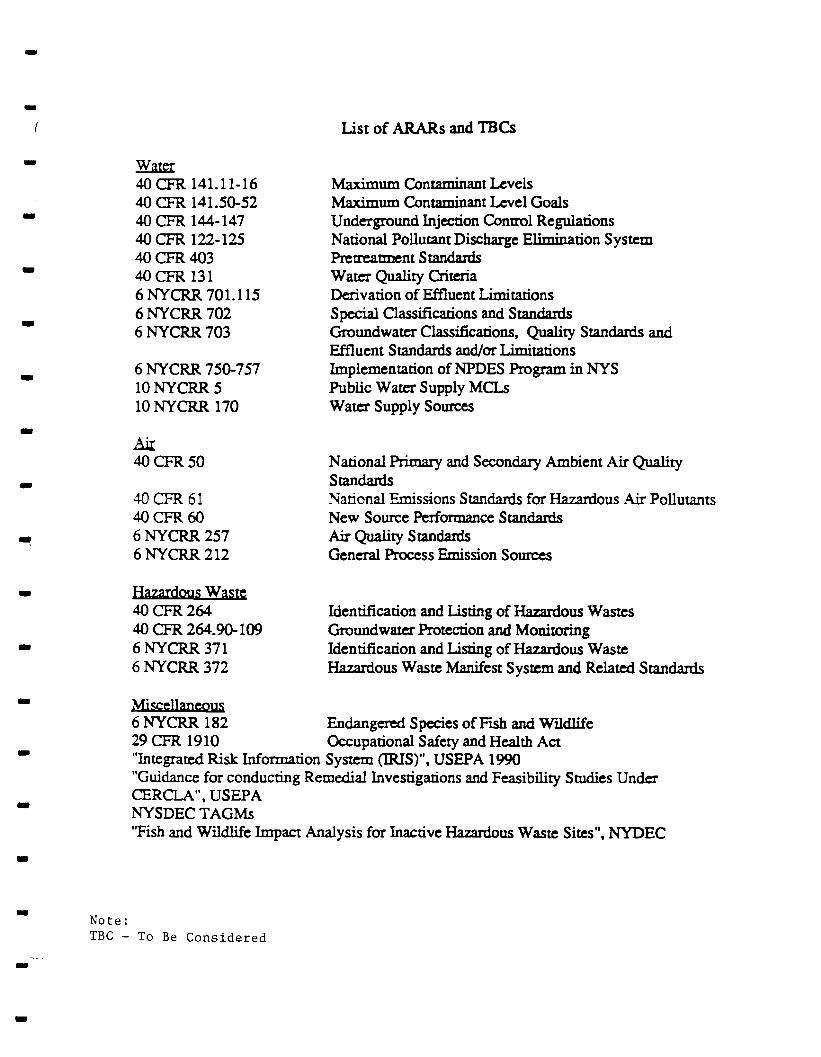
ARARs and TBCs
Detennination of Soil Cleanup Criteria
TAGM Scoring of Remedial Alternatives
Capital and Operational/Maintenance Cost Analysis
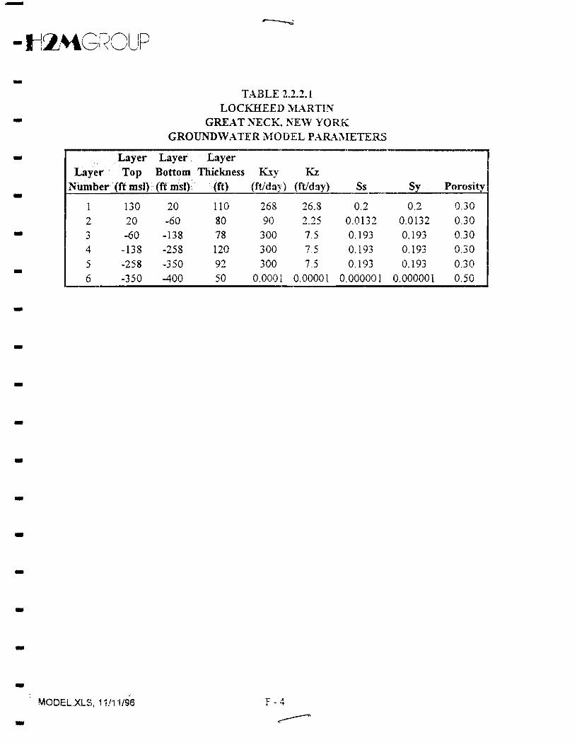
Groundwater Model Expanded Description
iv
-Il:lMGROUP • FEASmILITY STUDY REPORT
OPERABLE UNIT I -Lockheed Martin Tactical Defense Systems Division of
Lockheed Martin Tactical Systems, Inc. (Former Unisys Corp. Site) -
Great Neck, New York
NYSDEC Site ID #130045 -January 1997 -
1.0 Introduction- On December 13, 1991, Unisys Corporation (Unisys) entered into an Administrative Order on
Consent (AOC) with the New York State Department of Environmental Conservation (NYSDEC). Prior
to that time the site was placed on the NYSDEC Inactive Hazardous Waste Disposal Site List and was -classified as a Class 2 site. The site was given NYSDEC ID Number 130045. The AOC required
completion of Interim Remedial Measures (IRM) and a Remedial Investigation/Feasibility Study -(RIfFS). In May 1995, Loral Corporation (Loral) purchased certain assets and liabilities of Unisys
including the Unisys Great Neck, NY facility. In 1996, the electronics and systems integration•
-businesses of Loral were acquired by Lockheed Martin Corporation (Lockheed Martin) and subsequently
renamed Lockheed Martin Tactical Systems, Inc. With this purchase, Lockheed Martin has assumed
immediate responsibility for the AOe. Two Interim Remedial Measures (lRMs) have been implemented
at this site for groundwater and soil. Both IRMs are currently still in operation.
• In 1995, NYSDEC divided the site into two, separate operable units. Operable Unit I includes the
portion of the project area owned by Lockheed Martin (i.e. 94 acres of land as described in Section 2.0). -Operable Unit II includes land immediately surrounding the site. This document represents the
Feasibility Study (FS) for Operable Unit I.-The purpose of this FS is to evaluate methods to prevent, minimize, or eliminate the release of- hazardous substances from the site and to minimize the risk to human health and the environment. This
FS is consistent with NYSDEC's Technical and Administrative Guidance Memorandum (TAGM) HWR
90-4030, entitled "Selection ofRemedial Actions at Inactive Hazardous Waste Sites". Other NYSDEC -TAGMs have also been used to guide the technology and remedial action screening processes. The
specific objectives for the Operational Unit I FS are as follows: ---
- ttlMGROUP • Contain the existing groundwater conditions on-site; -• Reduce the mass of volatile organic compounds (VOCs) in the on-site groundwater and;
• Reduce the mass and level of VOCs found in on-site soils. Soil VOC levels are to be reduced to - levels which are protective of groundwater.
The FS uses current and site-specific information, such that previously implemented remedial -actions are considered and alternative technologies are identified and ranked based on the following
criteria:-• Compliance with Federal Applicable, or Relevant and Appropriate Requirements (ARARs) and
NY State Standards, Criteria, and Guidelines (SCGs) - • Overall protection of human health and environment
• Short-term effectiveness • Long-term effectiveness and permanence - • Reduction of toxicity, mobility, and volume
- • Implementability
• Cost
2.0 Background Information -2.1 Site Description
The site consists of 94 acres of land located at the intersection of Marcus Avenue and Lakeville --
Road between the Village of Lake Success and the Town of North Hempstead in Nassau County, New
York (see Figure 1). The property has a main manufacturing building, and six smaller buildings located
immediately south of the main building, which total approximately, 1.5 million ft. sq. Three small
recharge basins are located in the southwest comer of the property adjacent to Lakeville Road. The
recharge basins collect snow melt and rain runoff from the roof and parking lots. Potable water from the -municipal water supply has also been discharged to the basins after use for non-contact cooling purposes.
The majority of the remaining property is used for parking. -2.2 Site History - The facility was originally designed and built in 1941 by the United States Government and was
operated under contract by the Sperry Gyroscope Company, a division of Sperry Rand Company, until - 1951. In 1951, the government sold the property to Sperry. Sperry merged with Burroughs Corporation
in 1986 to form Unisys Corporation. On May 5, 1995 Loral Corporation acquired the assets of Unisys
Defense Systems, a division of Unisys Corp. In 1996, the electronics and systems integration businesses -of Loral were acquired by Lockheed Martin. Originally, the property included an additional 55 acres
with a large manufacturing building immediately to the east of the present property. However, this --
2-
• ttlMGROUP
• building was demolished, the property was sold to a developer in the 1970s, and the present day Triad
- Business Park was constructed.
- At present, the site houses administration offices and engineering departments. In the past, the
facility has been used to manufacture a wide range of defense-related products. Past manufacturing
processes included a casting foundry, etching, degreasing, plating, painting, machining and assembly.
- Chemicals used during manufacturing at the plant included halogenated and non-halogenated
hydrocarbon solvents, cutting oil, paints and fuel oils as well as inorganic plating compounds.
- In the past, unused solvents were reportedly delivered to the site, used on-site, and removed in 55
- gallon drums. Currently, all process chemicals are located in the chemical storage area and are handled
per Resource Conservation and Recovery Act (RCRA) requirements. A search of corporate archives was
conducted and little or no written record of either wastes generated in the past, or historical waste
• handling practices, was available. The above summary of historical waste handling practices is primarily
based upon interviews of former employees.
- 2.3 Remedial Investigation Summary
• The following sections briefly summarize the data and results presented in the Remedial
Investigation (RI) report and the Supplemental RI report. The reader is encouraged to review these
- reports since the following sections are only a summary.
- 2.3.1 Summary of Soil Investigation
The purpose of the soils investigation performed during the RI was to identify areas on-site that
might have been affected by past site activities and which may in tum be affecting groundwater. The
- soils investigation included the collection of soil samples from the former dry wells, from monitor well
borings, and from the Long Island Lighting Company (LILCO) substations located on the southwest
- comer of the property. In addition, five soil-gas surveys were performed as part of the soil investigation.
Methods and results are described in more detail in the RI report and the results are summarized as
- follows.
• The soil-gas surveys detected VOCs at three of the six survey locations (grids 3, 4 and 6). The
- detections at grids 3 and 4 were relatively low and not indicative of significant impact. The
results for grid 6 (the dry well area) were elevated as expected and were consistent with
previous analytical results from this area which showed elevated levels of TCE, PCE and 1,2
- DCE. During the supplemental RI soil samples were collected at grids 3 and 4 and analyzed
for the full Target Compound List (TCL). Results of the analysis indicate that VOCs were not
detected.
-3 -
-tl~GROUP
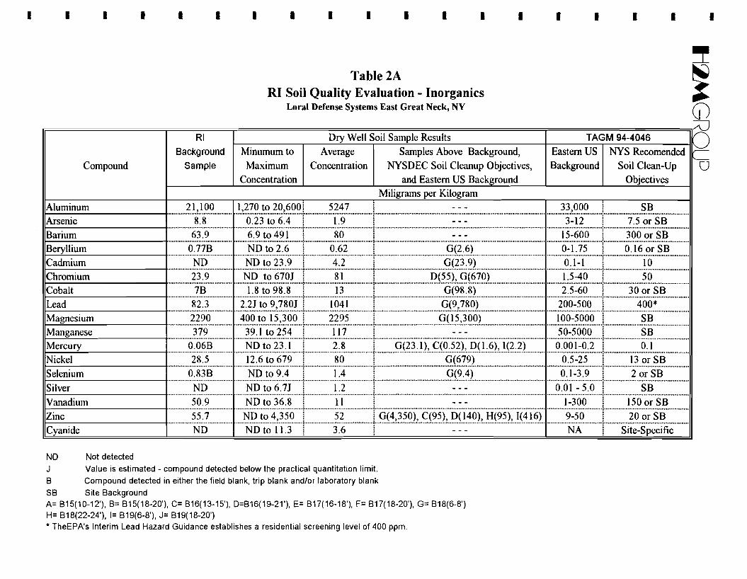
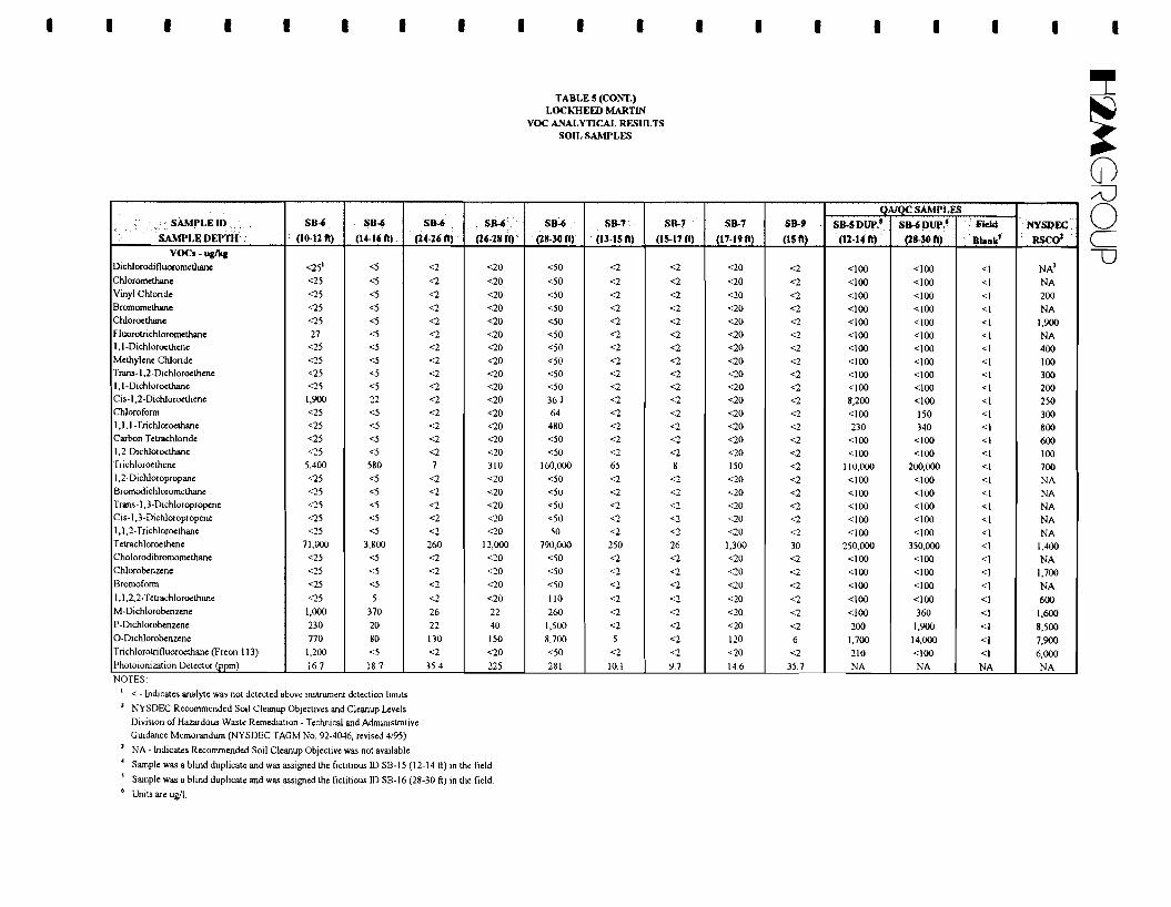
• • As shown on Table 2A, analysis of soil samples from the dry well soil borings confirmed the
presence of elevated levels of VOCs and indicated that elevated levels of some metals may also
be present. The highest concentrations of VOCs and metals detected during the RI were• associated with sludge material encountered while boring through the location of the former
dry wells. In addition, low levels of semi-VOCs and trace concentrations of pesticides and
PCBs were detected. -• VOCs were not detected in the LILCO substation samples; however, low levels of semi-VOCs
were detected in all four samples and PCBs were detected in one sample at 0.39 mglkg. •
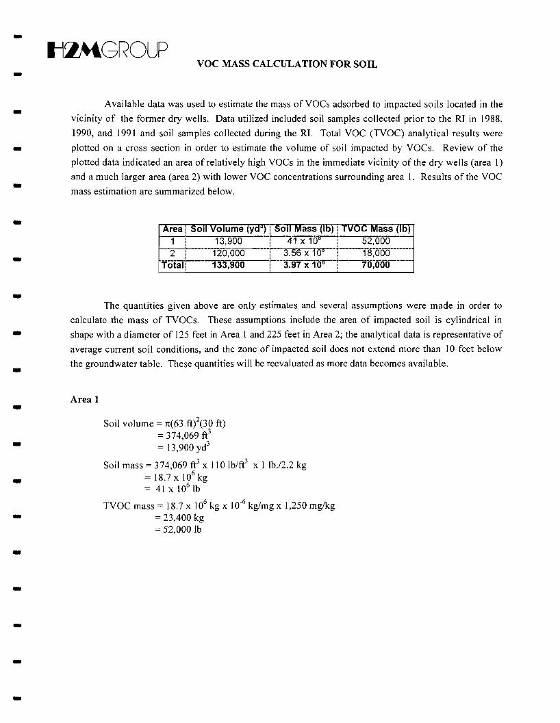
- Results of the RI soil investigation indicate that the only area of VOC-affected soil is in the vicinity
of the former dry wells (Southeast comer of the main building), where soil-vapor extraction and
groundwater recovery and treatment systems are already in place as part of the IRM. The primary VOCs
of concern, PCE, TeE and 1,2 DCE, were not detected in any of the LILCO substation samples and the -semi-VOCs that were detected were not consistent with those found on-site. As a result, it does not
appear that the compounds detected on the LILCO property are related to site activities. •
2.3.2 Summary of Groundwater Investigation - The main objectives of the groundwater investigation were to define the hydraulic characteristics of
the site and to define the vertical and horizontal extent of groundwater impacts. The investigation
included the testing and repair of Lloyd Well No. N 1802, the installation and sampling of on-site and -off-site monitoring wells, a review of existing off-site well records and water quality, water-level
monitoring, aquifer testing and groundwater flow modeling. Methods and results are described in more -detail in the RI report and the results are summarized as follows.
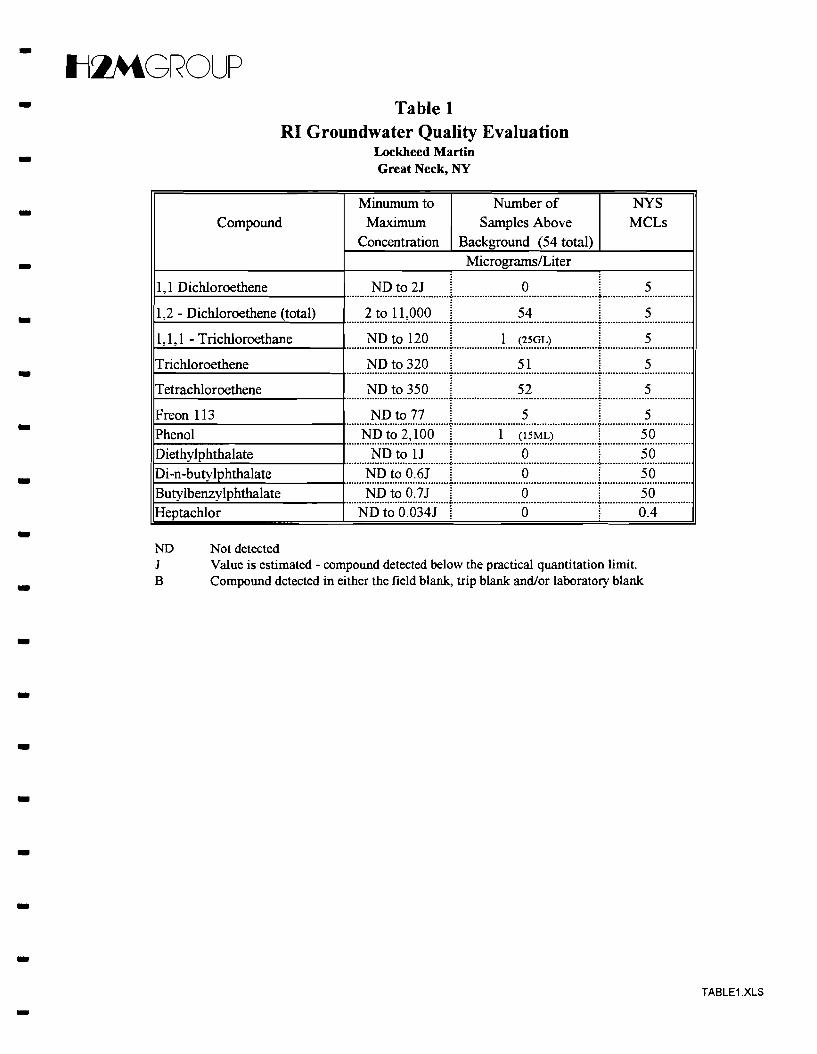
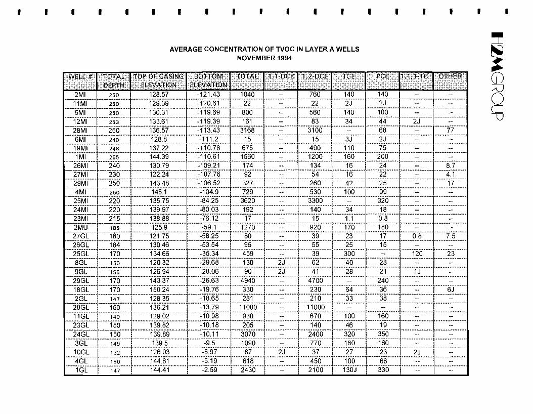
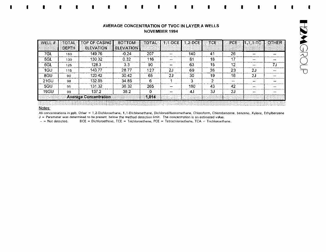
-• • The groundwater sampling results show that VOCs, primarily PCE, TCE and 1,2-DCE, were
detectable in most of the wells sampled as part of the RI (see Table 2). Four semi-VOCs were
randomly detected in nine wells at relatively low concentrations (0.6 to 1 ug/L) with the exception of phenol which was detected in 1ML and 15GL at 45 and 2,100 ug/L, respectively. One pesticide, heptachlor, was detected in the samples. PCBs were not detected in any of the
groundwater samples. --
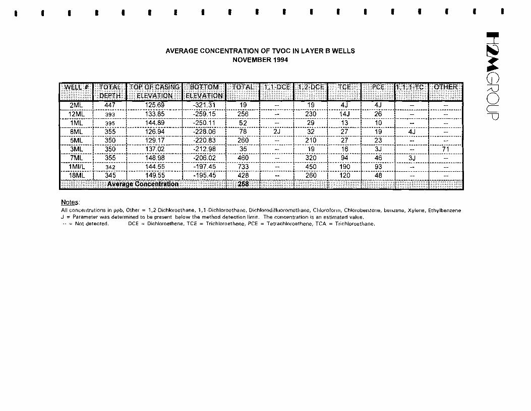
• The highest concentration ofVOCs in groundwater beneath the site is present within the Upper and Intermediate Magothy. Concentrations of VOCs in the deeper portions of the Magothy aquifer are significantly lower.
• The analytical data indicates that metals concentrations in all wells, with the exception of 15ML, were below NYS Maximum Contaminant Levels (MCLs) for drinking water. Well -
-15ML is located upgradient of the site in the Sears parking lot and only one metal, cadmium,
was detected above MCLs.
-4 -
• Il~GROUP
•
--
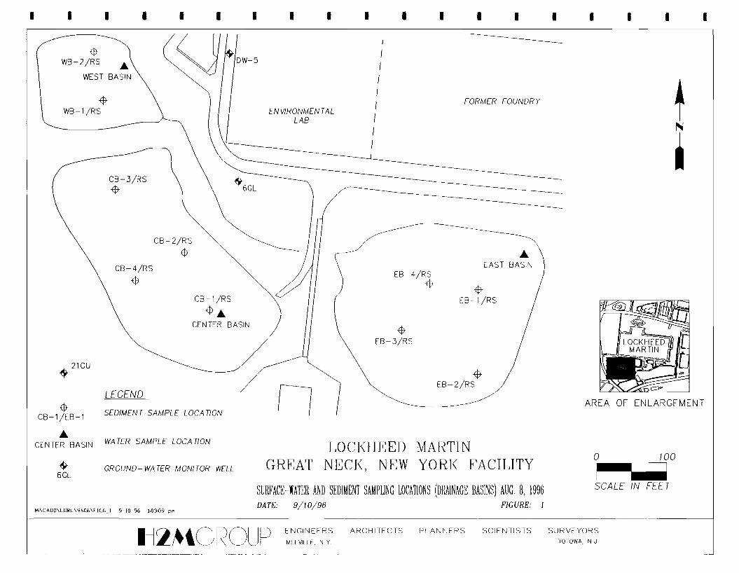
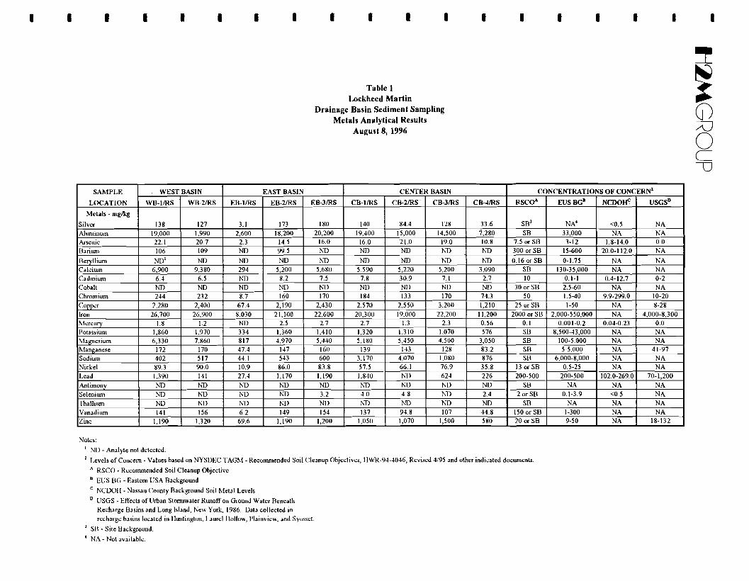
2.3.3 Summary of Surface Water and Sediment Investigation
As part of the RI, surface-water and sediment samples were collected from the three on-site
recharge basins to determine if they have been affected by site activities. The basins receive surface
water runoff from the entire site through a network of on-site storm and roof drains and are located in the
southwestern corner of the site. Additionally, potable water from the municipal water supply has also
been discharged to the basins after use for non-contact cooling purposes.
•
-•
-
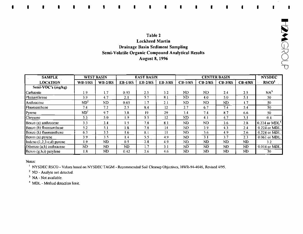
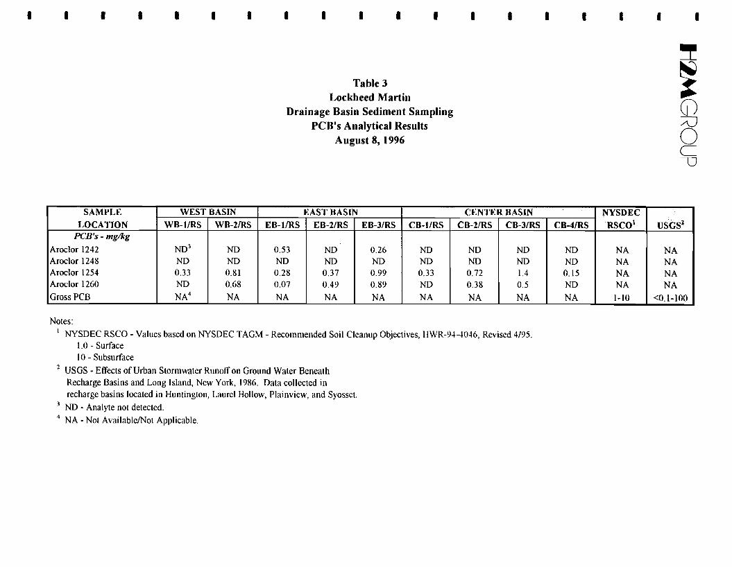
Results of the recharge basin sampling showed the presence of low levels of VOCs, semi-VOCs,
pesticides and PCBs in the sediment samples. In contrast, the only organic parameter detected in the
surface-water samples was 1,2-DCE, at a maximum concentration of 2 ug/L. Many of the inorganic
parameters analyzed were detected in both the sediment and surface-water samples with the
concentrations and number of detections being greatest in the sediment samples. Another noticeable
pattern is the fairly even distribution of detections and concentrations between the three basins, which is
not surprising considering that they are interconnected and receive runoff from the same sources.
-----
The results of the recharge basin sampling are not inconsistent with the primary nature and purpose
of the recharge basins, which is to collect storm-water runoff from surrounding parking lots, walkways,
rooftops and unpaved areas and allow it to drain to the underlying sediments. Many of the compounds
detected in the recharge basin samples are leached from the surrounding pervious and impervious
surfaces or transported on sediments and deposited in the basins. As runoff collects in the basins,
sediments picked up enroute settle to the bottom and become part of a natural filter which removes
impurities from the water as it drains through the bottom of the basin. Over time, these impurities
concentrate in the bottom sediments as is evident by the results presented above. Studies of recharge
basins on Long Island show that the compounds and concentrations detected in these samples are not
uncommon (Ku, 1986).
•
-2.3.4 Summary of Air Quality Investigation
Results of a flux chamber test performed during the RI indicate that VOCs are not being emitted
from the subsurface of the site in the southeast corner of the main building. Methods and results of the
air quality investigation are described in more detail in the RI report.
- 2.4 Interim Remedial Measures
--
The purpose of the interim remedial measures (lRM) is to minimize the risk to the environment and
public health during the performance of RIfFS activities and prior to NYSDEC's Record of Decision
(ROD). IRM activities at this site consist of both groundwater and soil gas remediation technologies.
Performance of the groundwater remediation IRM is discussed in the IRM Work Plan dated January 27,
- 5
- tl:»tGROUP - 1993. Performance of the soil remediation IRM is discussed in the IRM Work Plan dated December 10,
1993.-Both remediation systems have been in operation since shortly after the Work Plans were approved
by the NYSDEC. Results of the remedial activities are reported to the NYSDEC on a monthly basis. In -short, the groundwater treatment system has treated approximately 840 million gallons of water and
removed approximately 8,000 Ibs. of volatile organic compounds (VOCs) to date. The soil-vapor - extraction and treatment system has treated and removed approximately 35,000 Ibs. ofVOCs to date.
- 3.0 Identification and Screening of Remedial Action Technologies
3.1 Introduction
Remedial actions at the site should strive to attain New York State Standards, Criteria, and -Guidelines (SCGs) and Federal Applicable, or Relevant and Appropriate Requirements (ARARs) or
other applicable Federal and state environmental standards. Potentially applicable federal ARARs fall -within three categories: Chemical-Specific, Action-Specific, and Location-Specific. NYSDEC has
elected to categorize its ARARs as SCGs and has also divided SCGs into the aforementioned three - categories. Each category is briefly described below.
• Chemical-Specific ARARs - Usually technology or risk-based numerical limitations or- methodologies that, when applied to site-specific conditions, result in the establishment of
acceptable concentrations of a chemical that may be found in, or discharged to, the ambient
environment. -• Action-Specific ARARs - Usually technology or activity-based requirements or limitations on
actions taken with respect to hazardous substances. These requirements typically define- acceptable treatment, storage, and disposal procedures for hazardous substances during the
implementation of the response action.
• Location-Specific ARARs - Restrictions placed on the concentration of hazardous substances -or the conduct of activities solely because the activities occur at a special location. These
requirements relate to the geographical or physical position of the site rather than the nature of- the materials or the proposed remedial action. These requirements limit the type of remedial
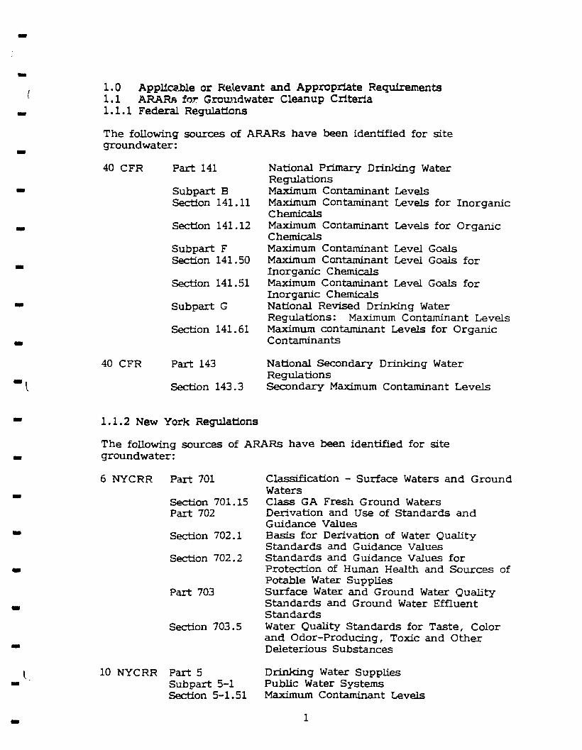
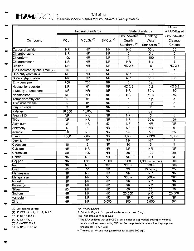
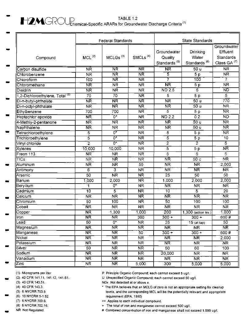
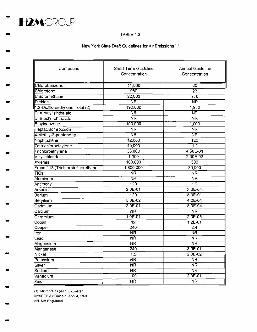
action that can be implemented and may impose additional constraints on a cleanup action. -Appendix B contains a list of chemical-specific ARARs/SCGs for groundwater cleanup criteria,
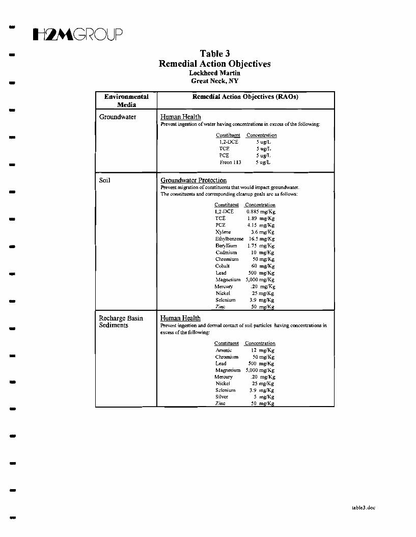
groundwater discharge criteria, air emissions, soil cleanup criteria, and transport and disposal criteria. -3.2 Remedial Action Objectives
-- The purpose of identifying remedial action objectives (RAOs) is to establish cleanup goals for
protecting human health and the environment through reduction of the volume and mobility of
6-
--
tl~GROUP
constituents of concern. Action has already been taken to achieve the RAOs through the IRMs
implemented to date. The RAOs identified for the site are media-specific and include the following: -• Exposure Route(s) and Receptor(s)
• Constituent(s) of Concern- • Acceptable Contaminant Level(s)
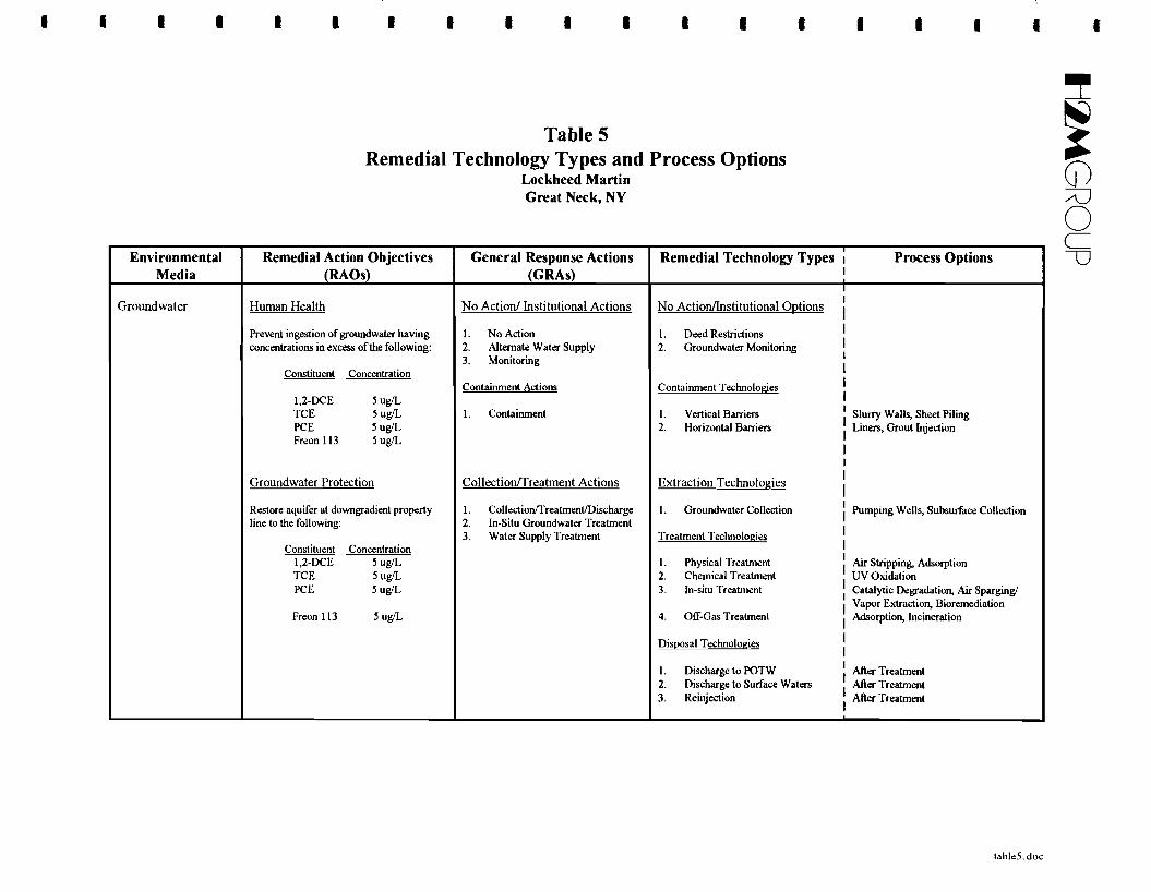
- 3.2.1 Determination of Groundwater Remedial Objectives
Groundwater cleanup levels are based on New York State (NYS) drinking water standards as
indicated in Chapter I State Sanitary Code, Subpart 5-1, Public Water Systems (March 11, 1992). NYS -drinking water standards are found in Appendix B, Table 1-1 "Chemical-Specific ARARs for
Groundwater Cleanup Criteria." Organic compounds detected during the RI well sampling were --
tabulated and compared to groundwater cleanup levels on Table 1. As shown on Table 1, only four
VOCs (i.e., 1,2-dichloroethene, trichloroethylene, tetrachloroethylene, and Freon 113) were considered
constituents of concern.
- Phenol was detected in one well (l5ML) above drinking water standards; however, 15ML is located
upgradient of the site in the Sears parking lot. In addition, the analytical data indicates that metals
concentrations in all wells, with the exception of 15ML, meet drinking water standards. Only one metal, -cadmium, was detected in 15ML. The detection of cadmium and phenol in 15ML appears to be
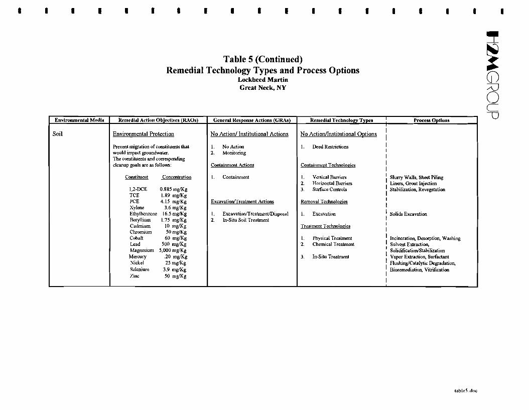
unrelated to the site and the compounds will not be considered as constituents of concern in the FS. -3.2.2 Determination of Soil Remedial Objectives
-- Soil cleanup levels were determined using procedures outlined in the NYSDEC TAGM # HWR-94
4046 entitled "Determination of Soil Cleanup Objectives and Cleanup Levels." Results of the RI
indicate that the only area of VOC affected soil is in the area of the former dry wells (southeast comer of
the main building). During the RI five borings were advanced through the probable source of the VOCs
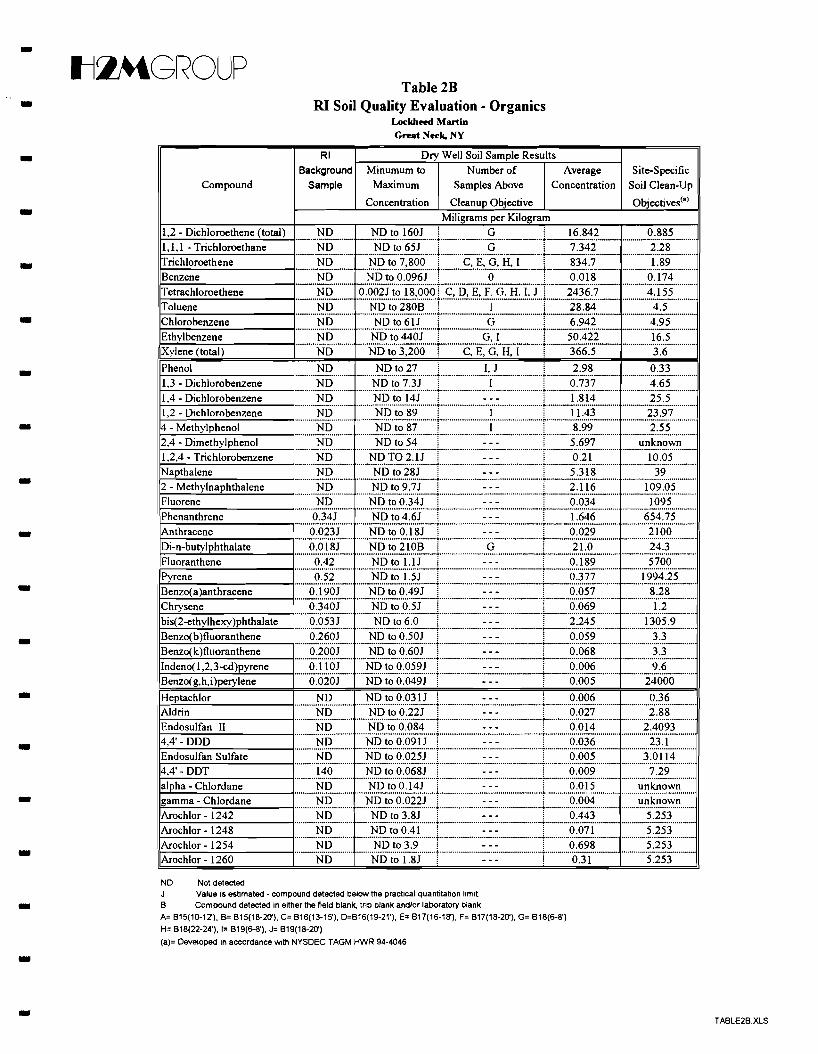
and two soil samples were collected per boring for TCL analysis. As shown on Tables 2A and 2B, -results of the analysis indicate that organic and inorganic compounds were detected in the vicinity of the
former dry wells. Although VOCs are present in groundwater from this source area, inorganics have not -been detected in downgradient groundwater above drinking water standards.
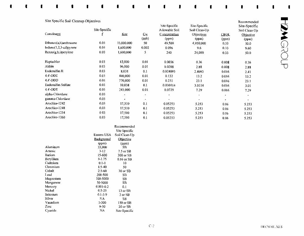
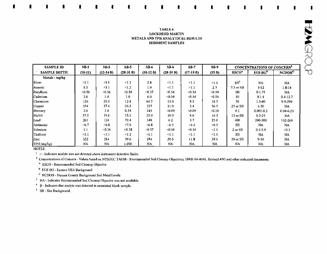
- As shown on Table 2A, inorganic concentrations for the 10 dry well soil samples collected as part of
the Remedial Investigation were compared with site background levels, Eastern US background levels - from TAGM 94-4046, and NYSDEC recommended soil cleanup objectives from TAGM 94-4046
(Determination of Soil Cleanup Objectives and Cleanup Levels). Results of the inorganic soil quality -7-
-Il~GROUP
- evaluation indicate that five samples do not meet NYSDEC soil cleanup objectives for inorganics. As
- shown on Table 2A, the greatest number of compounds with elevated concentrations, and the highest
concentrations, were detected in the 6 to 8 foot sample from B-18 followed by the same sample interval
from B-19. The sample descriptions contained on the geologic logs show that these samples consisted of - a very moist, black, silty material (sludge) with a strong odor. Borings and samples other than B-18 and
B-19 with elevated inorganic levels included: 1) B-16 (19-21 ') with chromium, mercury and zinc, and 2)
- B-16 (13-15') with mercury and zinc.
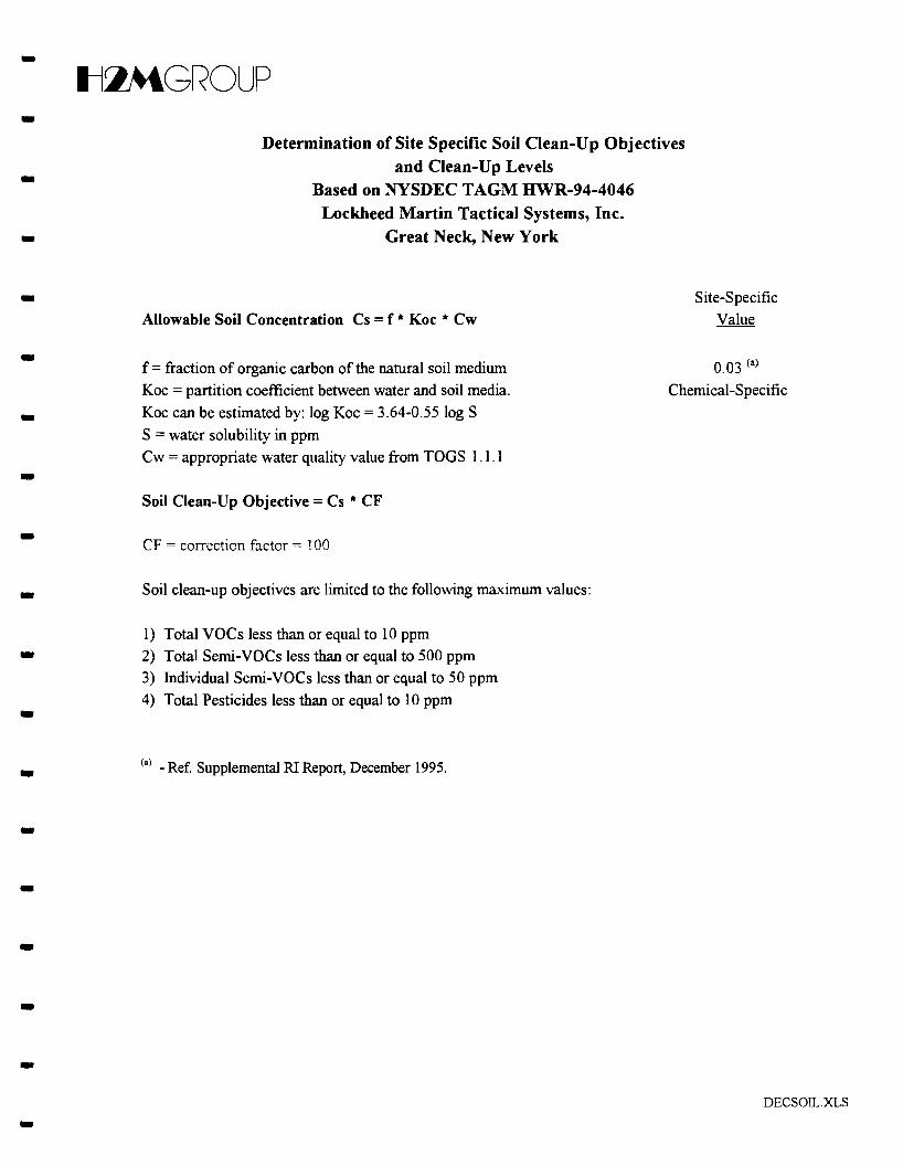
- Site soil cleanup objectives for organics which are protective of groundwater are based upon the
water/soil partitioning theory which is conservative in nature and assumes that the soil and groundwater
- are in direct contact. The theory predicts the maximum amount of organic chemicals that may remain in
soil and not violate drinking water standards. The water-soil equilibrium theory is based on the ability of
organic carbon in soil to adsorb organic compounds. The model used to determine site specific
- allowable soil concentrations and site specific soil cleanup objectives was found in NYSDEC TAGM 94
4046.
- Cs = f x Koc x Cw Where: Cs = allowable soil concentration
- f= the fraction organic carbon of the soil; use site specific f= 0.03 (3%) (reference Supplemental RI Report, December 1995)
Koc = 3.64 - 0.5510g S; S = water solubility in ppm
- Cw = the appropriate water quality value from TOGs 1.1.1
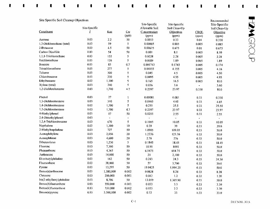
- Results of the model as calculated using a site specific organic carbon fraction of 0.03 (3%) are
contained in Appendix C and are summarized as the "Site Specific Soil Cleanup Objectives" on Table
- 2B. As shown on Table 2B, the model identified eight (8) VOCs and three (3) semi-VOCs as
constituents of concern in soil.
- The identification of the inorganic and organic compounds associated with the dry well area as
constituents of concern is inherently conservative since the samples used in the evaluation were collected
- from the probable source and are not representative of the average concentrations for the area targeted
for remediation. Specifically, concentrations of VOCs and inorganics quantified in the dry well sludge
- (samples B-18 and B-19, 6 to 8 feet) are several orders of magnitude higher than those concentrations
detected in the other soil boring samples collected from the same general area. In later sections of this
- report, specific processes and technologies applicable to mitigating these compounds will be considered.
The FS evaluation will focus on mitigating the VOC constituents of concern in the dry well sludge
because this material could serve as an on-going source of VOC contamination to groundwater.
-- 8
-Il~GROUP
- Removal of the sludge would also serve to further minimize the potential for a release of inorganics to
groundwater, even though downgradient groundwater has not been affected by inorganics. The RAOs
for the dry well area are identified on Table 3. -One other soil sample, Sample #14 collected from Soil Gas Grid 3, contained arsenic above the -
-NYSDEC recommended cleanup objective of 7.5 mg/kg and above the NYS background concentration
range of 3 to 12 mglkg cited in TAGM 94-4046. Arsenic was detected in this soil sample at 24.9 mg/kg.
However, a study conducted by the United States Geological Survey (USGS) to estimate natural
background concentration ranges of inorganics in soil identified an observed range of <0.1 mg/kg to 73
mglkg for arsenic in the Eastern United States (ref. Element Concentrations in Soils and Other Surficial -Materials of the Conterminous United States, Professional Paper 1270, Shacklette and Boerngen). The
concentration in natural background soils as noted in the USGS study support the conclusion that the -arsenic level detected in Sample #14 is not significant. Concentrations of volatile and semi-volatile
organic compounds, pesticides and PCBs detected in this sample were all below their respective - NYSDEC recommended soil cleanup objective. No action is proposed for Soil Gas Grid 3.
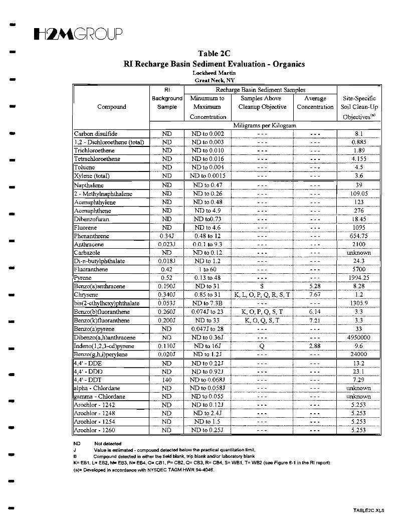
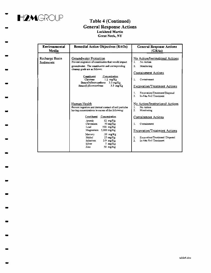
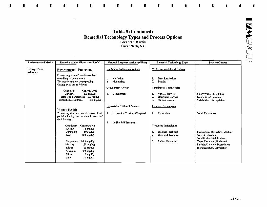
-- 3.2.3 Determination of Sediment Remedial Objectives
Sediment remedial objectives were also evaluated using site specific cleanup levels developed in
accordance with NYSDEC TAGM # HWR-94-4046 entitled "Determination of Soil Cleanup Objectives
and Cleanup Levels" as described in detail in the previous section. Results of the water/soil partitioning
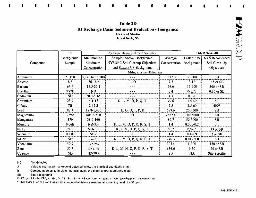
model evaluation for recharge basin sediments are found on Table 2C. As shown on Table 2C, five (5) -organic compounds were found above the site specific cleanup objectives. Inorganic concentrations for
the recharge basin samples were compared with site background levels, and with Eastern US background - levels and NYSDEC-recommended soil cleanup objectives from TAGM 94-4046. Results of the
inorganic sediment quality evaluation indicate that nine (9) metals were above NYSDEC soil cleanup - objectives.
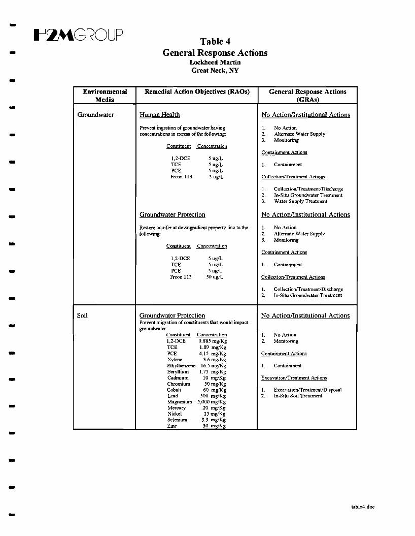
3.3 General Response Actions -In the previous section, RAOs were identified which would be used to ensure that any remedial
action taken at the site would reduce the potential direct contact exposure and reduce toxicity volume and -mobility. In order to achieve these objectives, it is necessary to determine specific technologies and
processes that may be applicable for implementation. To identify the technologies and processes, it is- first necessary to identify General Response Actions (GRAs) that may achieve the RAOs. The GRAs are
broad categories for which specific technologies and processes are then selected that, when implemented, - will achieve the RAOs. The GRAs identified, based on the site conditions, are:
-9 -
- Il~GROUP
- • No ActionlInstitutional Actions
• Containment Actions
- • ColiectionlExcavationiTreatment Actions
Typically, a "No Action" alternative is evaluated to provide a baseline on which potential
technologies could be measured. The "No Action" alternative is not evaluated further in this FS because -remedial actions have already been initiated and accomplishment of some level of the RAOs has already
been achieved. Remedial actions already implemented at the site include institutional controls,-environmental monitoring, and removal. The context in which these technologies and processes are
evaluated further is in tenns of additional or enhanced implementation relative to what has already been - done at this site. Table 4 presents the media-specific GRAs identified for the site. As can be seen, the
- GRAs may be applicable to more than one RAO.
3A Identification and Initial Screening of Remedial Technologies and Process Options
An initial screening process was carried out by first expanding each GRA into a series of -technologies and processes available for addressing remediation of the site. Many available technologies
and processes were furthered subdivided into specific process options. Each of the technologies -identified as a part of a GRA was screened against the RAOs, taking into account the expected
effectiveness and implementability. Proven technologies received prime consideration, but innovative - technologies were also considered. Table 5 presents the initial identification of remedial technologies
and process options. -304.1 Technologies and Processes Eliminated from Evaluation
Following the initial screening process, options were eliminated from further consideration that -were not viable or because an RAO could not be obtained. Additionally, technologies that were
infeasible due to physical limitations or technological limitations were also eliminated from further-consideration. The following technologies and processes were eliminated from evaluation:
• No Action - certain GRAs have been implemented - • Containment Technologies - do not reduce volume or toxicity • Biotreatment - technical limitations • Discharge to POTW - excessive discharge volumes make this option infeasible for groundwater -• Discharge to Surface Waters - physical and technical limitations for groundwater
--
304.2 Technologies and Processes Selected for Evaluation
The following technologies and processes will be evaluated further:
• Groundwater Monitoring (currently conducted)
• Groundwater Collection (currently conducted)
• 10 -
-Il:»tGROUP • Physical Treatments (carbon adsorption, air stripping) -• Chemical Treatments (UV oxidation)
4.0 Evaluation of Remedial Technologies and Process Options
Several technologies and process options were identified in the previous section that may achieve -the RAOs appropriate to the site. The initial screening also identified technologies and processes that
were not technically implementable at the site. The remaining potentially feasible technologies and -
-process options were evaluated and scored in this section for effectiveness and implementability as
required by NYSDEC. The following sections provide a brief description of each technology and - process screened using TAGM-HWR-90-4030, including a generalized evaluation of compliance with
the RAOs.
4.1 Groundwater Process Options and Remedial Technologies
4.1.1 Pump and Treat -4.1.1.1 Groundwater Collection
Groundwater collection is an effective means of preventing plume migration and reducing- concentrations of constituents. Groundwater collection is typically conducted through the use of
groundwater extraction wells or subsurface collection systems such as trenches or drains. Extracted- groundwater typically requires treatment prior to discharge. Groundwater collection using extraction
wells has already been implemented as an IRM at the site. -4.1.1.2 Carbon Adsorption
Carbon adsorption is the oldest and one of the most commonly used water purifying processes. -Carbon adsorption is a physical process in which organic compounds are removed from groundwater by
adsorbing onto the highly porous surface structure of the carbon. This technology has proven to be very - effective for the removal of VOCs and can be easily implemented. Removal efficiencies greater than
95% are usually achieved. -4.1.1.3 Air Stripping
Air stripping is also one of the oldest and most commonly used technologies for the removal of -VOCs in groundwater. Air stripping is a physical operation in which dissolved molecules are transferred -
11 -
--
ti~GROUP
from a liquid into a flowing gas or vapor stream. The driving force for the mass transfer is provided by
the concentration gradient between the liquid and the gas phases and is governed by Henry's Law. This
technology has proven to be very effective for the removal of VOCs and can be easily implemented. -Removal efficiencies greater than 95% are usually achieved. Air stripping may require vapor stream
treatment prior to discharge to the atmosphere. -4. I. 1.4 UV Oxidation - UV oxidation involves the addition of an oxidant such as hydrogen peroxide and using ultra-violet
light as a catalyst. The oxidant and catalyst generate hydroxyl radicals which react with organic
compounds to produce by-products of carbon dioxide and water. UV oxidation is a proven technology -for the complete destruction ofVOCs in groundwater and can be easily implemented. -
4.1.1.5 Groundwater Discharge
Groundwater recovery and treatment requires discharge of treated water. Reinjection is the one - discharge option identified for this site. Reinjection involves the reintroduction of treated groundwater
into the aquifer through a series of deep wells. Reinjection not only recharges the aquifer with potable - water but expedites the remediation process by increasing the rate of VOC recovery through "flushing"
an aquifer. Reinjection is currently used at the site as part of an IRM.-4.1.1.6 Off-Gas Treatment Technologies
Some technologies and process options for the treatment or removal of VOCs in groundwater -generate a vapor stream that may require treatment or removal ofVOCs. The feasible off-gas treatments
_ k identified for this site consist of regenerative carbon adsorption and catalytic incineration. Each off-gas
treatment technology is discussed in the foHowing sections.
- 4.1.1.6.1 Regenerative Carbon Adsorption
The same principal of liquid phase carbon is utilized; however, adsorbing VOCs in an air phase is
more efficient then adsorbing VOCs in a liquid phase. BasicaHy the air is heated to reduce relative -humidity, then the air is passed through the carbon to adsorb the VOCs. Carbon adsorption is a physical
process in which VOCs are removed by adsorbing onto the highly porous surface structure of the carbon. -Once the carbon is saturated it is regenerated with low pressure steam. The steam is condensed and the
liquid phases are separated. The water phase can be recirculated into the stripper and the organic phase - is drummed and removed. Two carbon beds are typically required so that while one bed is being
- utilized, the other can be regenerated.
-12 -
-Il~GROUP
4. I. I .6.2 Catalytic Incineration -Catalytic incineration is similar to thermal incineration except that the gas stream is passed through
a catalyst to oxidize the combustible emissions. The catalyst is used to initiate and promote combustion -at much lower temperatures than those required for thermal incineration. Particularly for VOCs,
catalytic incinerators are capable of complete destruction of the compounds while cost-effective-incinerators are capable of 90-95% destruction efficiencies. Catalytic incinerators have economical
advantages over thermal incinerators due to the lower temperature of combustion and resulting natural - gas savings.
4.1.2 In-Situ Groundwater Treatment -4.1.2. I In-Situ Catalytic Degradation
Catalytic degradation involves the addition of an oxidizer and a catalyst to groundwater. The -oxidant and catalyst generate hydroxyl radicals which react with organic compounds to produce by
products of carbon dioxide and water. This process is typically conducted in-situ using an extensive-network of injection wells located throughout the plume area.
- 4.1.2.2 In-Situ Air Sparging
Air sparging is a process where air is introduced under pressure through soils below the water table
to increase the rate of volatilization of constituents in the saturated zone. Air sparging is generally used -at sites with unconsolidated materials such as sand and gravel, or relatively permeable fonnations and is
generally used in conjunction with vapor extraction to effectively reduce VOCs levels III soil and -groundwater. Air sparging can also be used as a delivery mechanism for nutrients to promote
biodegradation-4.1.3 Groundwater Monitoring
.. - Groundwater monitoring provides a means of determining if groundwater has been affected by
constituents of concern. Should monitoring indicate the need, other actions may be taken to assure
human health and environmental protection. A groundwater monitoring program has already been
implemented at the site and serves as an indicator of groundwater quality and is used to evaluate current .. interim remedial measures.
.. 4.2 Soil Remedial Technologies
4.2. I Soil Vapor Extraction
Soil vapor extraction is the process of inducing a vacuum in the subsurface to volatilize and extract - VOCs through extraction wells and is generally used at sites with unconsolidated materials such as sand
and gravel, or relatively permeable formations. Soil vapor extraction is very effective at reducing VOC -13 -
- ttlMGROUP --
concentrations adsorbed to the soil in the vadose or unsaturated zone. This remedial technology will not
be effective on inorganic contaminants; therefore, an alternate remedial technology may be needed along
with soil vapor extraction.
---
4.2.1.1 Off-Gas Treatment Technologies
The soil vapor extraction process generates a vapor waste stream that requires treatment or removal
of VOCs from air. The feasible off-gas treatments identified for this site consist of regenerative carbon
adsorption and catalytic incineration. Each off-gas treatment technology is briefly discussed in the
following sections.
---
4.2.1.1.1 Regenerative Carbon Adsorption
Granular activated carbon would be utilized to remove VOCs from the soil gas of the SVE system
prior to discharge of the air stream to the atmosphere. Two carbon beds are typically required (one bed
stays on-line while the second bed is regenerated). This treatment technology is the same as that
described in Section 4.1.1.6. I for treating off-gases from the air stripping tower of the groundwater
remedial alternative.
---
4.2. I. 1.2 Catalytic Incineration
This treatment technology is the same as that described in Section 4. I.1.6.2 for the groundwater
remedial alternative. Catalytic incineration would be used to oxidize the combustible emissions from the
soil gas from the SVE system prior to discharge to the atmosphere. This technology is effective for
controlling emissions. Supplemental fuel (i.e., natural gas) may need to be provided in order for
effective operation of this system.
---
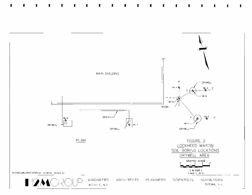
4.2.2 Removal of Soil
Soil removal would encompass the excavation of soil and sludge contained within inactive dry wells
that are in excess of the Site Specific Cleanup Objectives. Five (5) former dry wells are located to the
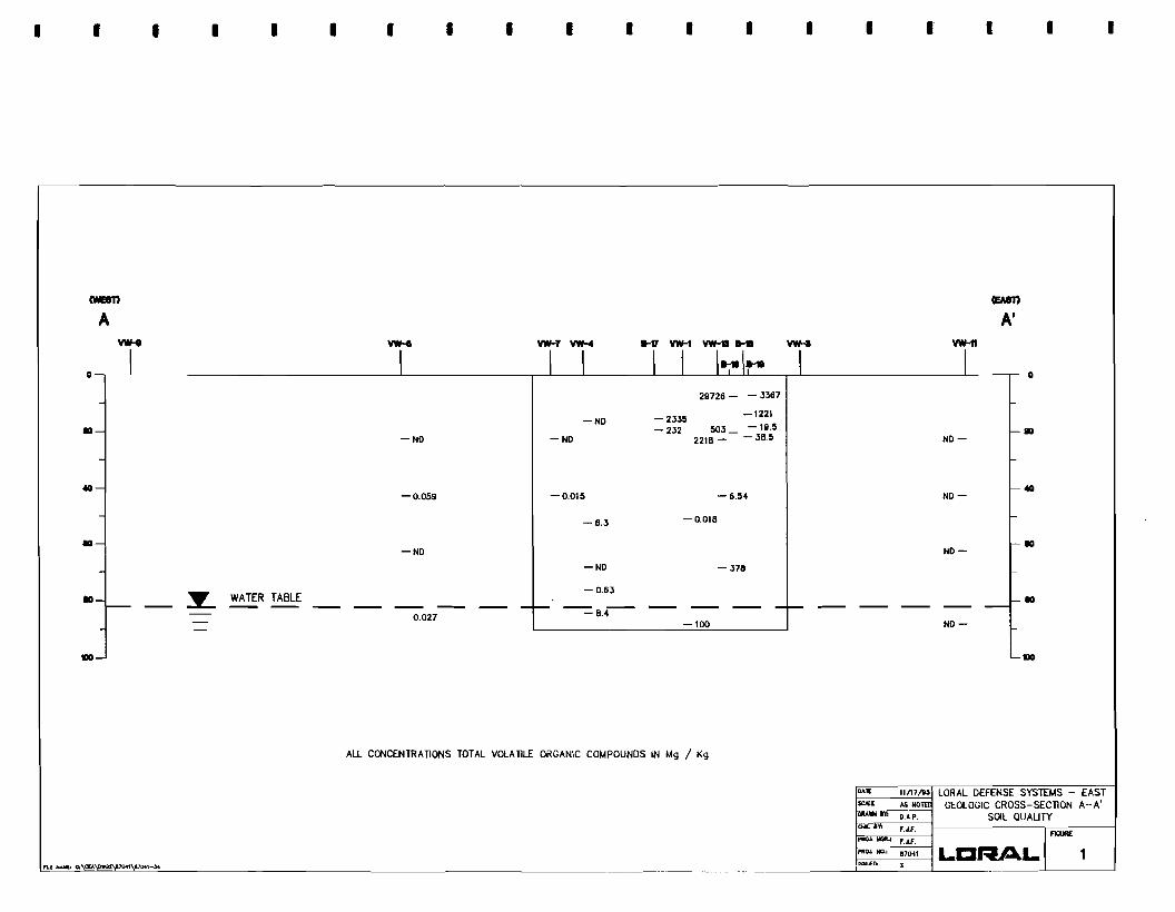
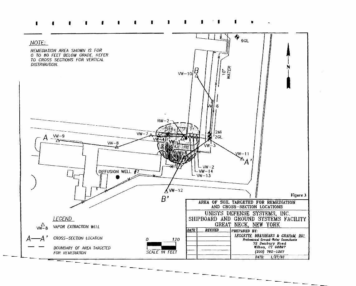
southeast of the main building. The locations of these underground structures are depicted in Figure 2
of Appendix G, Soil Borings and Dry well Area Map.
--
The three (3) dry wells located on the east of the building (where soil borings SB- I, SB-5 and SB-6
were advanced), are interconnected and has been utilized for the disposal of process wastewater.
Samples from soil borings SB- I, SB-5 and SB-6 identified the presence of elevated concentrations of
VOCs and metals, and also the presence of black silty soils (sludge). Soils from these three dry wells
will be excavated as a source area remedial action.
-- 14
- Il~GROUP
- Another dry well, located south of the southeast comer of the building, in the areas where boring
SB-7 was drilled and sampled, formerly received drainage from a truck loading bay. Reportedly, the
drainage flowed through an oil/water separator located immediately adjacent to the dry well prior to -entering the dry well. To the west of this dry well is the fifth below grade structure in the area where
boring SB-9 was drilled and sampled. According to facility personnel, underground tanks containing --
hydrocarbons had been located in this area; however, it is not certain as to whether a dry well was also
present at this location. The tanks were removed in 1989, and it is possible that the dry well, if it existed,
was removed when the tanks were excavated. Soil samples collected from borings SB-7 and SB-9 were
below the Site Specific Soil Cleanup Objectives; therefore, soil removal at these two locations is not- warranted, based on soil sampling data.
Removal of the contaminated sludge and soils from the three inactive dry wells near borings SB-I, -SB-5 and SB-6 would eliminate a potential source that may be impacting ground water. This response
action will also be effective in reducing the levels of inorganic constituents present in the dry well soils, -which would not be addressed by the soil vapor extraction system. Excavated soil would be transported
to a permitted off-site treatment/disposal facility. -- 4.3 Recharge Basin Sediment Remedial Technologies
Three remedial alternatives are being considered in this section to address the sediments in the
stormwater recharge basins. These alternatives include: 1) removing sediments by hydraulic dredging,
2) removing sediments by excavation, or 3) leaving the sediments in place but imposing land use and site -access restrictions to further minimize the potential for exposure.
--
4.3.1 Dredging of Sediments
Dredging of the sediments would take place with a hydraulic dredge. Dredged soil would be
dewatered on-site and transported to a permitted treatment/disposal facility, while water produced during
the dredging and dewatering operations would be recharged on-site, discharged to the local sewers, or - transported off-site to a permitted treatment/disposal facility, depending on the chemical and physical
characteristics of the water. The volume of metallic constituents would be reduced by removing
sediments containing these constituents. However, dredging could also release contaminants that are -bound in the sediment to groundwater.
--
4.3.2 Sediment Removal from Drainage Basins by Excavation
Sediment removal would take place with bulldozers and excavators. Prior to excavating, the basins
-would be drained. Standing water contained in the basins would be pumped to the local sanitary or
stormwater sewer system depending on local approvals. However, runoff of any rainwater during
15-
- tl:»tGROUP - excavation would have to be diverted so as not to flush contaminants into the groundwater while the
sediments are disturbed by excavation equipment. The excavated soil would be transported to a
permitted treatment/disposal facility. The volume of metallic constituents would be reduced by -removing contaminated sediments from the basins. However, excavating could also release
contaminants to groundwater that are otherwise immobile and are bound in the sediment. -4.3.3 Deed Restrictions - Administrative controls can be implemented to minimize potential threats to public health and the
environment.l£!,r the recharge basins, the primary concern associated with elevated metals in the- sediment is posed by potential contact exposure to human receptors, if or when the basins are no longer
active and the sediments become exposed. A deed restriction can be imposed on the portion of the site
where the recharge basins are located to alleviate this concetiiJ Deed restrictions are covenants -incorporated into a property deed which limits the use of the property. The deed will be executed by the
property owner and recorded in the office of the County Clerk of Nassau. The deed restriction will be --
written to prohibit modifications to the site without NYSDEC approval to prevent potential future
development on the basin property. In addition, engineering controls such as a security fence can be
constructed around the recharge basins to prevent trespassing of unauthorized persons.
- 5.0 Development of Remedial Alternatives
To develop potential remedial alternatives for the site, individual technologies and groups of
technologies/processes must be evaluated in general terms of effectiveness and implementability. This -evaluation must determine the applicability of specific technologies and process options in terms of their
ability to attain the RAOs for the site. From the set of remaining technologies and processes, remedial --
alternatives can be developed. The final alternatives incorporate different combinations of technologies.
Table 6 provides a summary of media-specific remedial alternatives for the site.
Based on this evaluation of technologies and process options, five (5) groundwater remedial- alternatives, two (2) soil remedial alternatives, and three (3) sediment remedial alternatives were
developed for this site and are discussed below. -5.1 Groundwater Remedial Alternatives
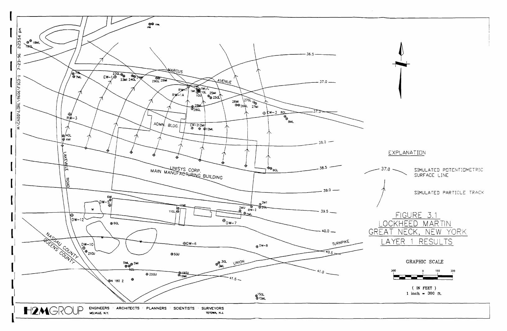
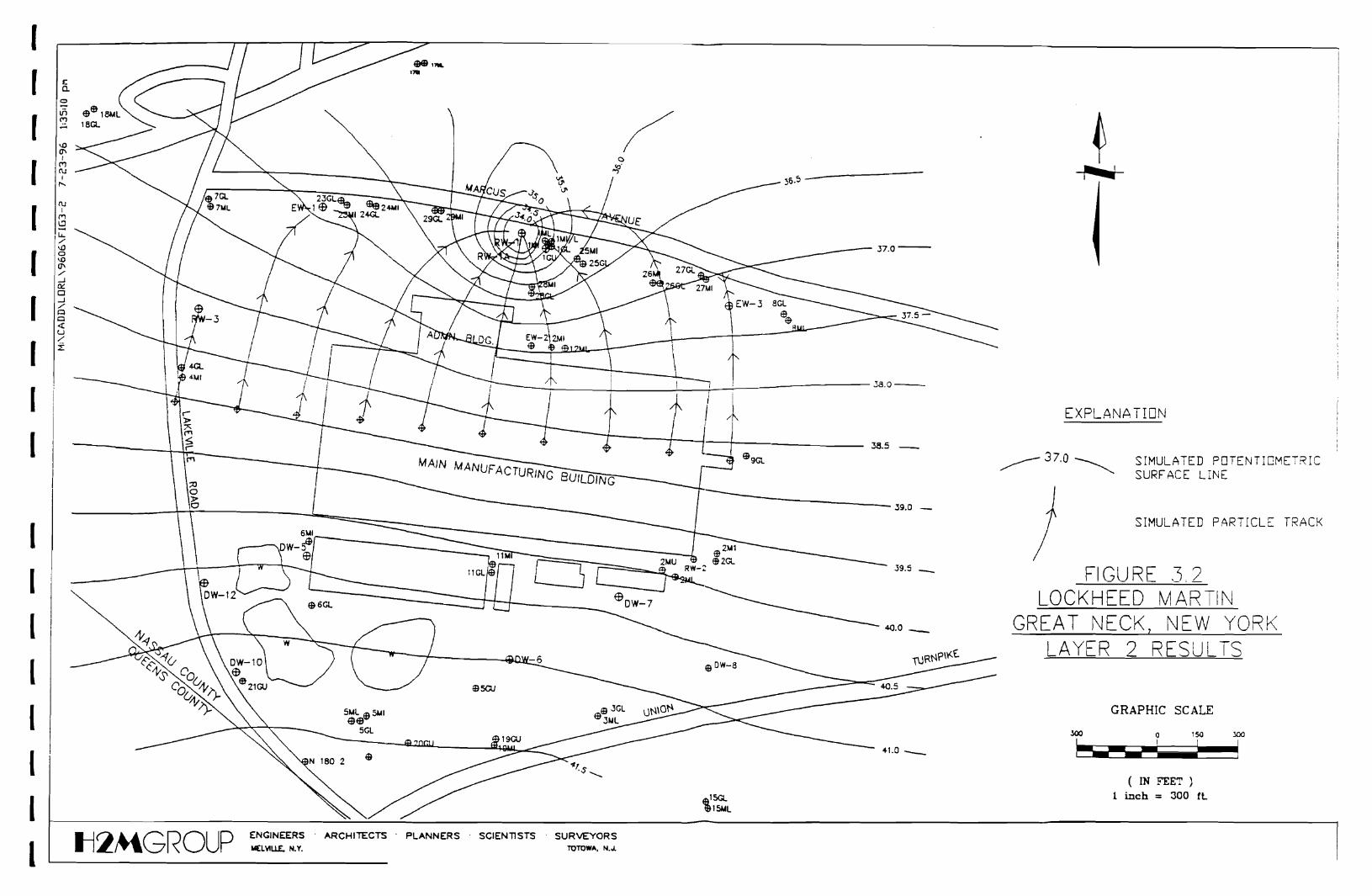
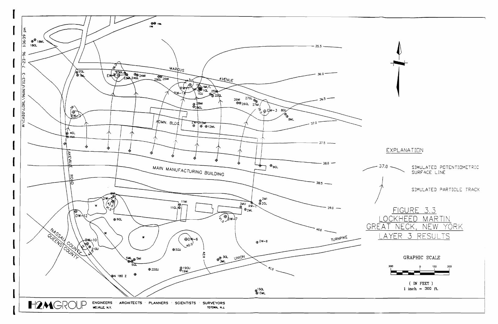
Groundwater monitoring, groundwater collection, and groundwater reinjection are included in all-alternatives under Section 5.1. Groundwater collection will be achieved through the pumpage of high
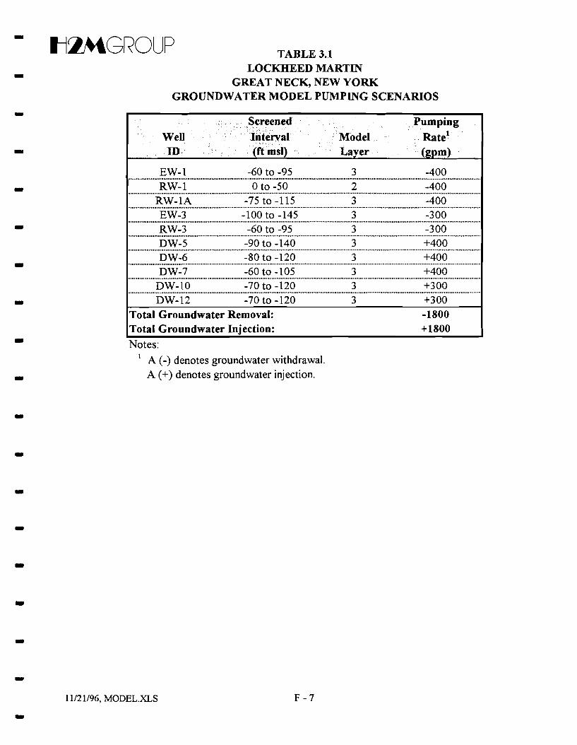
capacity recovery wells. The approximate pumping rates, locations, and quantity of recovery wells were - determined with a groundwater flow model. Based on the model, an estimated five extraction wells
-16-
- tl:lMGROUP • would be used to extract approximately 1,800 gallons per minute (gpm) of groundwater, and five
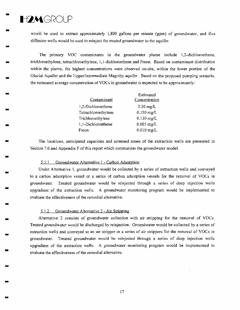
diffusion wells would be used to reinject the treated groundwater to the aquifer. -The primary VOC contaminants In the groundwater plume include· 1,2-dichloroethene,
trichloroethylene, tetrachloroethylene, 1, I-dichloroethene and Freon. Based on contaminant distribution -within the plume, the highest concentrations were observed on-site, within the lower portion of the
Glacial Aquifer and the Upper/Intermediate Magothy aquifer. Based on the proposed pumping scenario, - the estimated average concentration ofVOCs in groundwater is expected to be approximately:
• The locations, anticipated capacities and screened zones of the extraction weIls are presented In
Section 7.0 and Appendix F of this report which summarizes the groundwater model.
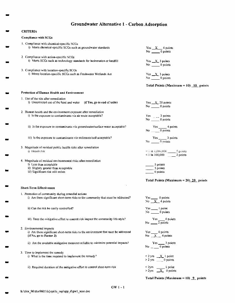
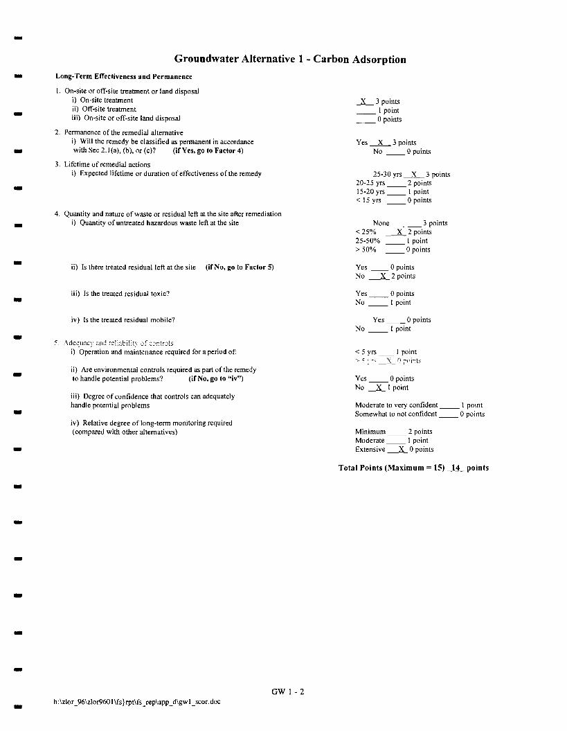
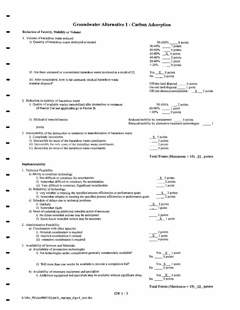
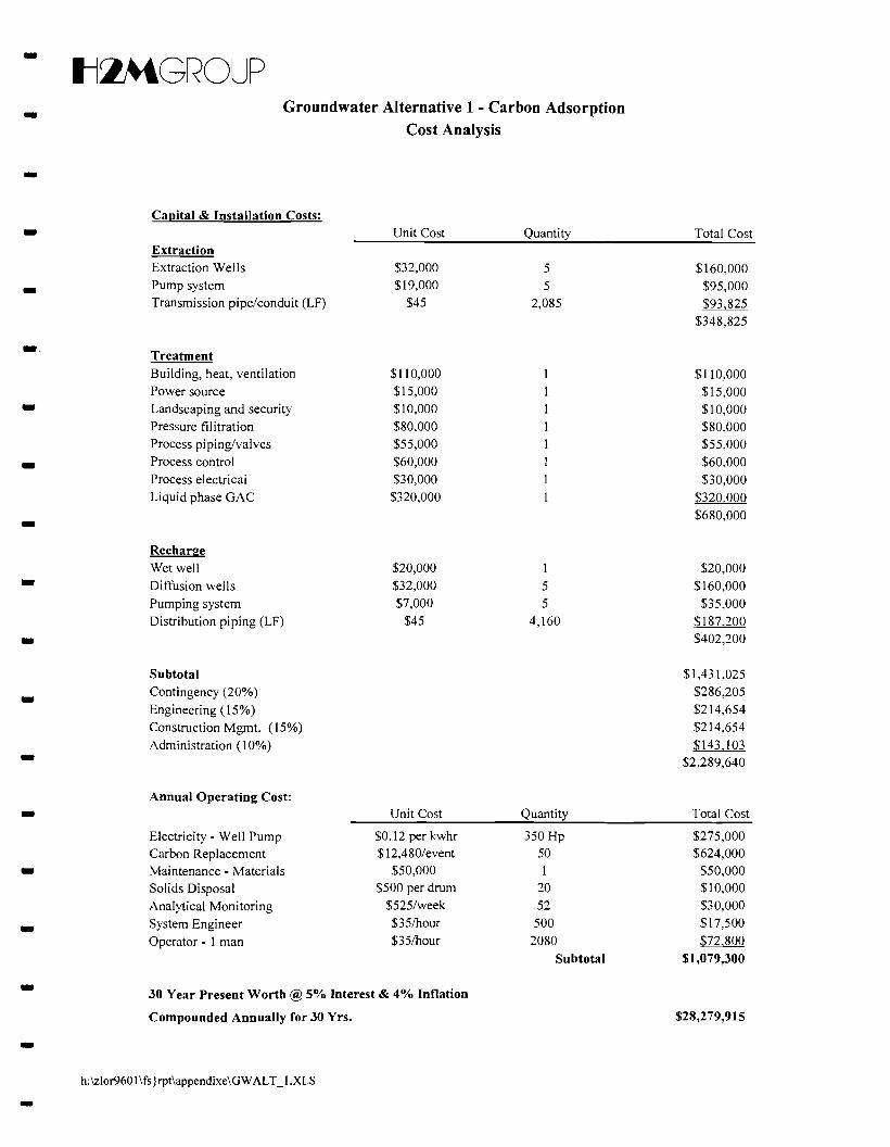
• 5.1.1 Groundwater Alternative 1 - Carbon Adsorption
Under Alternative 1, groundwater would be coIlected by a series of extraction weIls and conveyed •
to a carbon adsorption vessel or a series of carbon adsorption vessels for the removal of VOCs in
groundwater. Treated groundwater would be reinjected through a series of deep injection wells
upgradient of the extraction wells. A groundwater monitoring program would be implemented to -evaluate the effectiveness of the remedial alternative. -
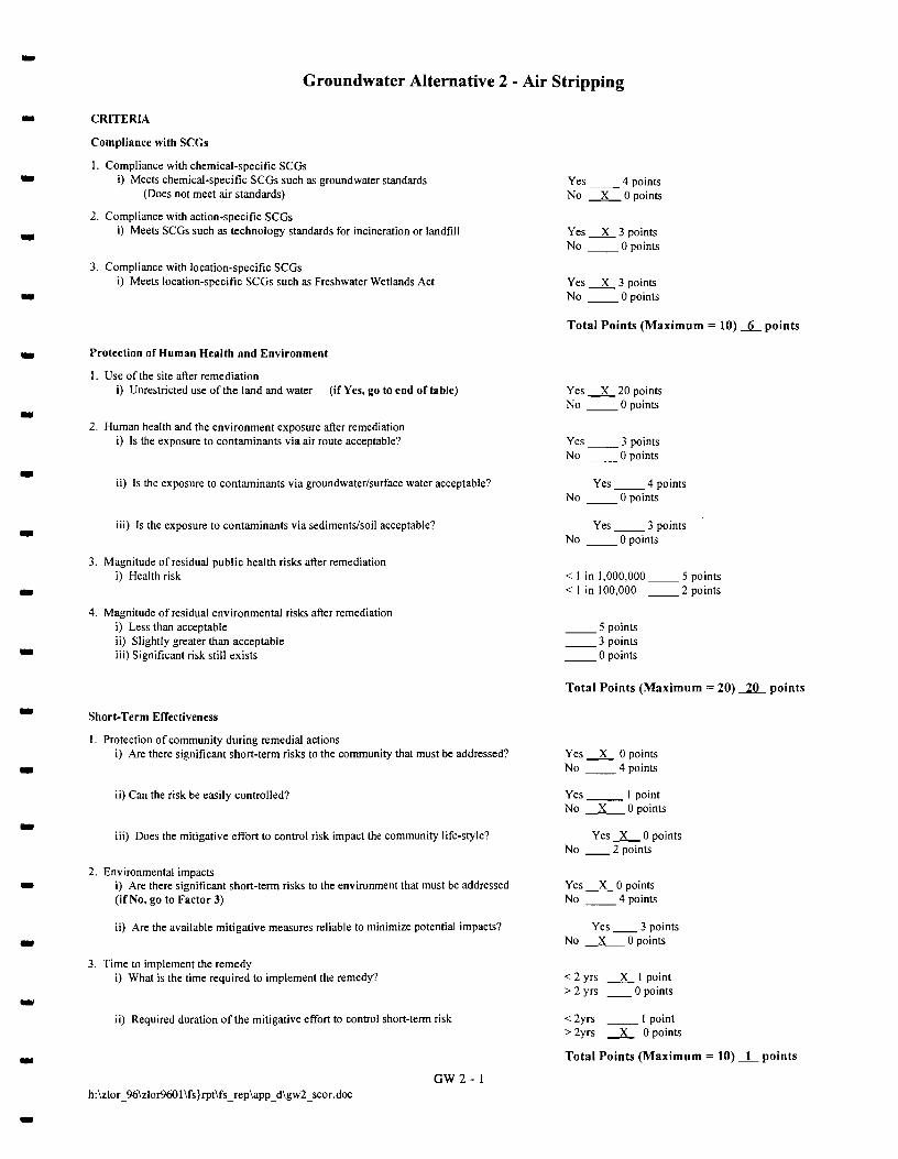
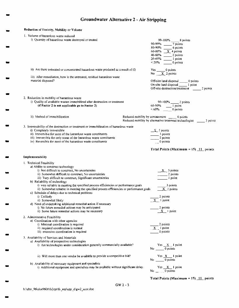
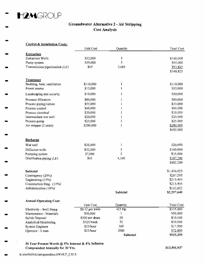
5.1.2 Groundwater Alternative 2 - Air Stripping
Alternative 2 consists of groundwater coIlection with air stripping for the removal of VOCs.- Treated groundwater would be discharged by reinjection. Groundwater would be coIlected by a series of
extraction weIls and conveyed to an air stripper or a series of air strippers for the removal of VOCs in- groundwater. Treated groundwater would be reinjected through a series of deep injection wells
upgradient of the extraction wells. A groundwater monitoring program would be implemented to
evaluate the effectiveness of the remedial alternative. -.. -
17-
- Il~GROUP
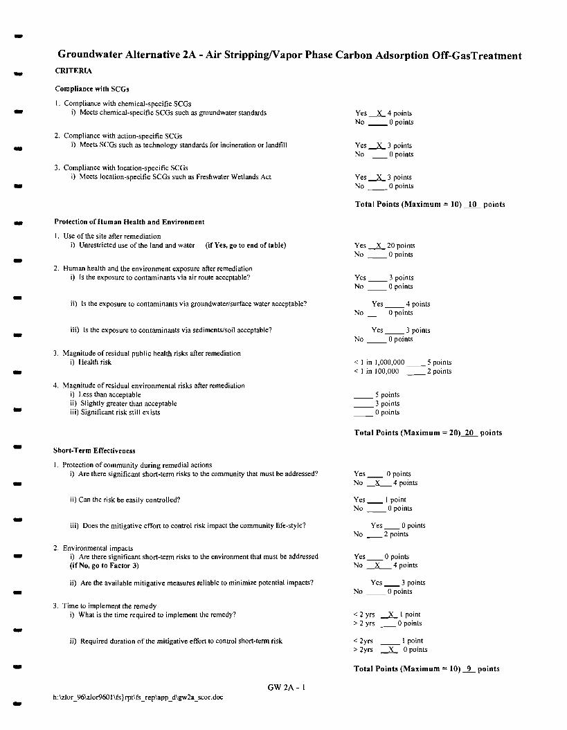
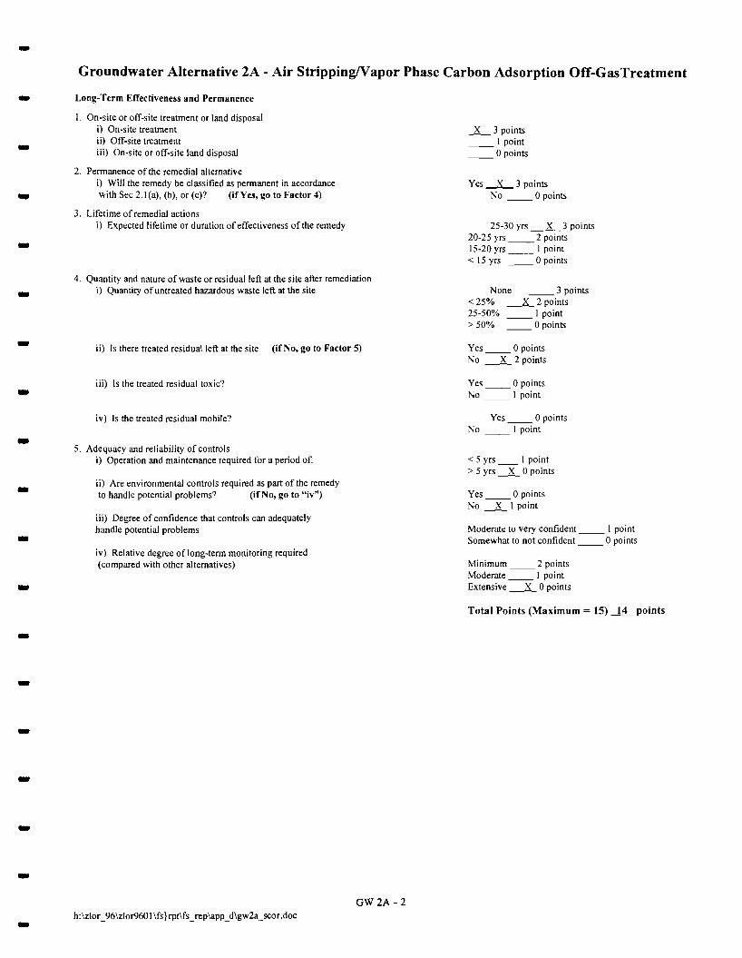
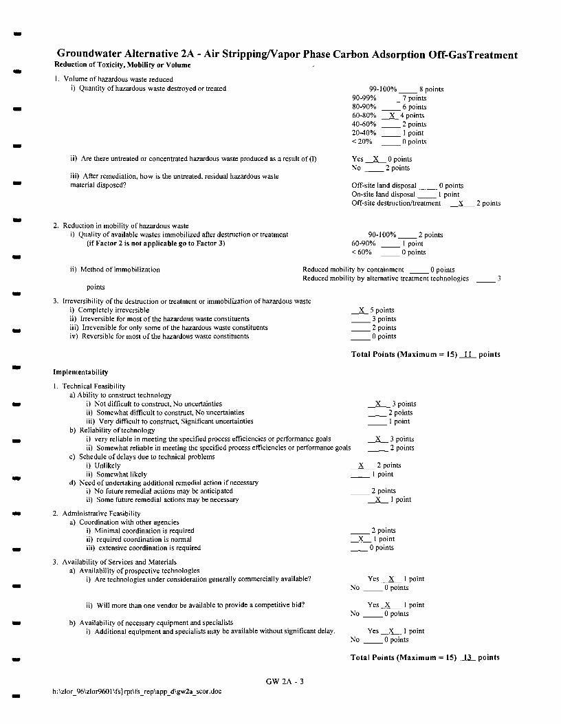
- 5.1.3 Groundwater Alternative 2A - Air StrippinWYapor Carbon Adsorption
Alternative 2A consists of groundwater collection with air stripping for the removal of VOCs. Air
emissions from the air stripper(s) would be treated by vapor carbon adsorption prior to discharge to the -atmosphere.
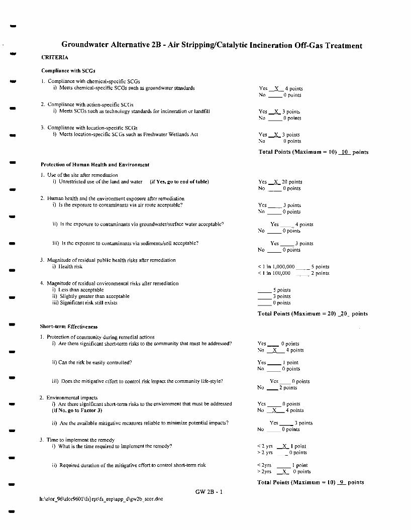
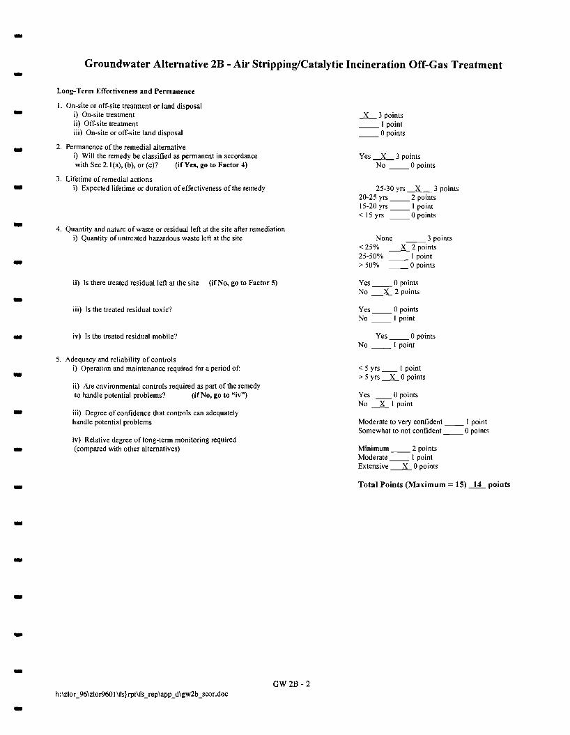
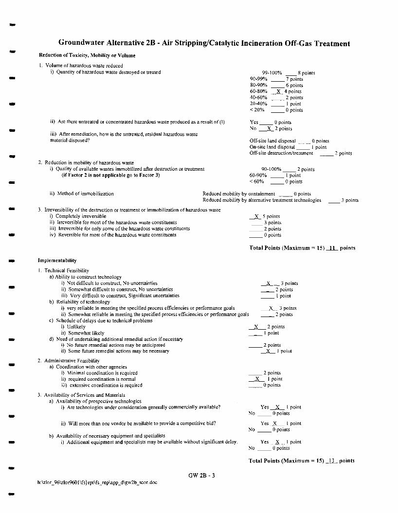
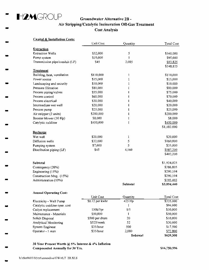
-5.1.4 Groundwater Alternative 2B - Air Stripping/Catalytic Incineration Off-Gas Treatment
Alternative 2B consists of groundwater collection with air stripping for the removal of VOCs. Air- emissions from the air stripper(s) would be treated by catalytic oxidation prior to discharge to the
atmosphere. Groundwater would be collected by a series of extraction wells and conveyed to an air - stripper or a series of air strippers for the removal of VOCs in the groundwater.
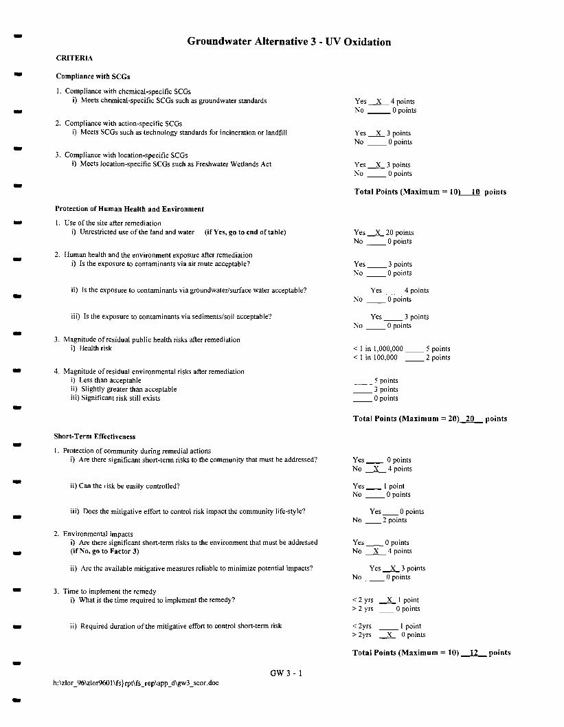
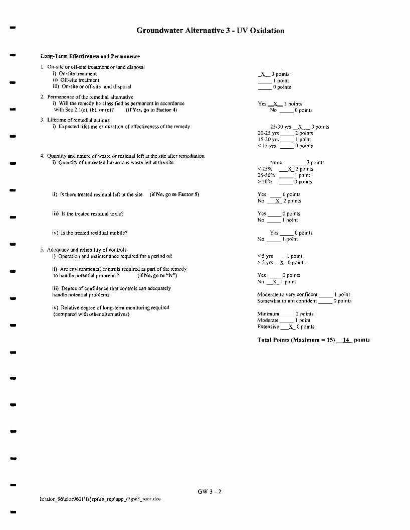
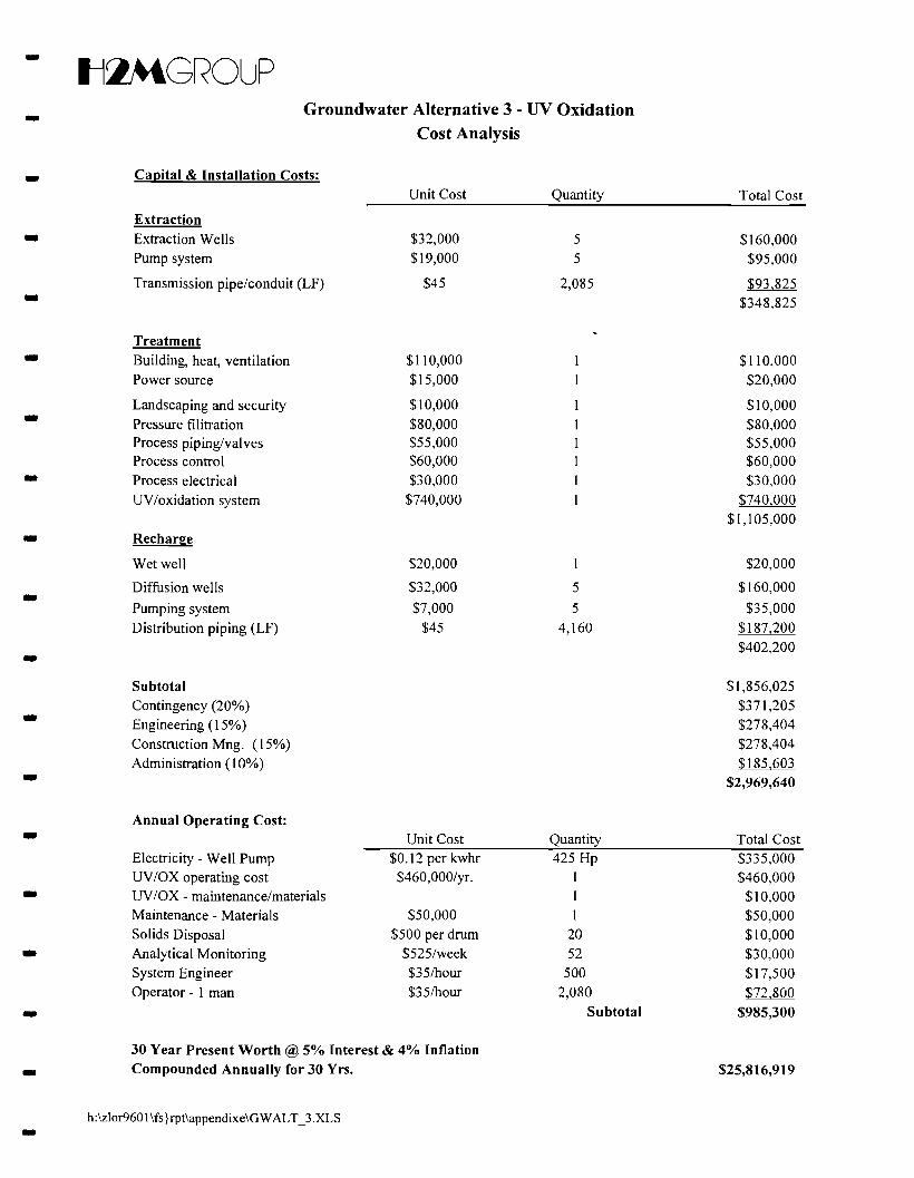
5.1.5 Groundwater Alternative 3 - UV Oxidation -Alternative 3 consists of groundwater collection with UV Oxidation for the removal of VOCs.
Treated groundwater would be discharged by reinjection. Groundwater would be collected by a series of-extraction wells and conveyed to a UV oxidation and carbon adsorption systems for the removal of
VOCs in groundwater. Treated groundwater would be reinjected through a series of deep injection wells - upgradient of the extraction wells. Because UV oxidation destruction generates by-products of carbon
dioxide and water, VOC emission control is not needed. However, UV lamps do require routine - maintenance in order to maintain VOC destruction efficiency and prevent the release of toxic
intermediate products into the atmosphere resulting from incomplete oxidation. A groundwater
monitoring program would be implemented to evaluate the effectiveness of the remedial alternative. -5.2 Soil Remedial Alternatives -
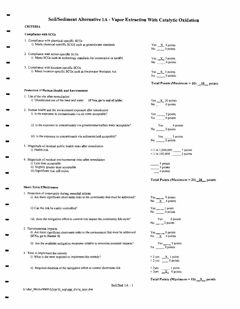
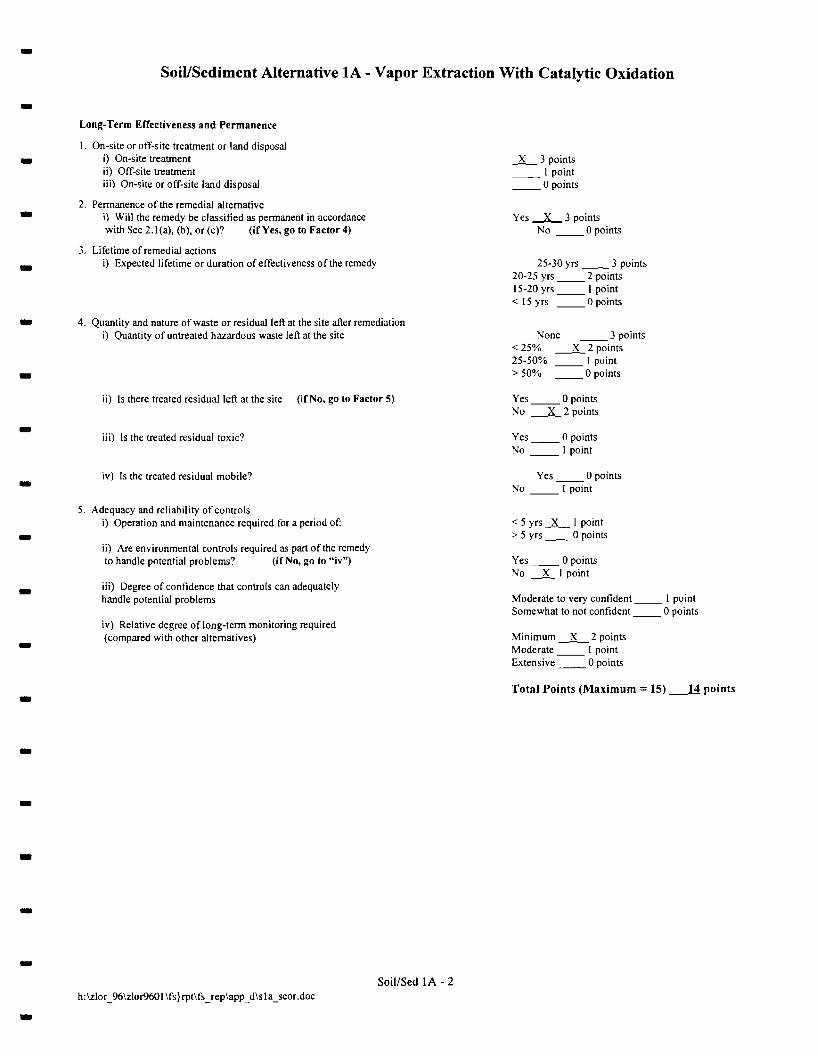
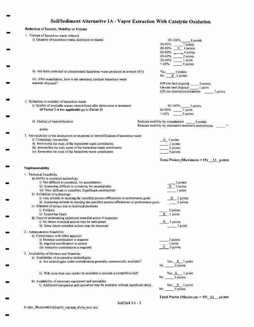
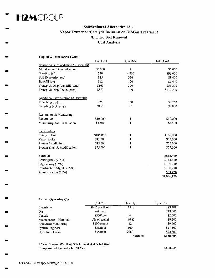
5.2.1 Soil/Sediment Alternative IA-Vapor Extraction/Catalytic Incineration Off-Gas
Treatment/Source Area Excavation - Alternative IA encompasses the continued operation of the existing in-situ soil vapor extraction
(SVE) system. Under this remedial alternative, off-gas treatment from the SVE system will utilize
catalytic incineration. The SVE system will be supplemented with excavation and removal of -contaminated soils and sludges within and below three inactive dry wells. Because this remedial
alternative employs use of the existing SVE system that was installed and currently operating as an IRM, -the SVE system will be reevaluated as part of this remedial alternative to confirm that the existing
system is operating effectively. Adjustments and modifications will be made to the SVE system as may - be warranted based on this evaluation.
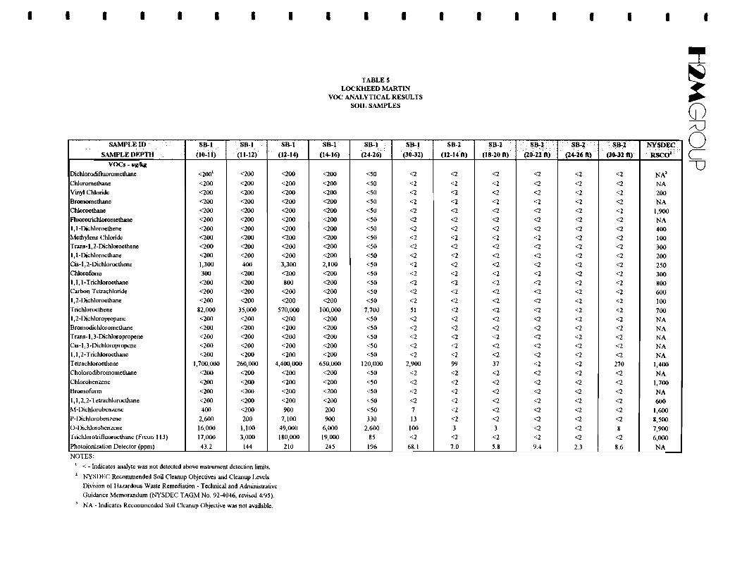
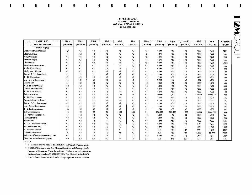
- Soil samples SB-1, 5, 6, and B-16 through B-19, previously conducted in the vicinity of and within
the three dry wells located to the east of the southeast comer of the main plant (see Figure 2 of Appendix-18-
• t1~GROUP
• G), indicated elevated concentrations of VOCs and inorganic compounds, as well as the presence of a
sludge. Removal of these soils and sludge will help to reduce the duration of the operating time for the
• SVE system as well as remove inorganics that are present in the dry well soils. During the soil boring
program, a clay layer was encountered at approximately 30 to 32 feet below grade. The analytical data
from the borings indicate that concentrations of VOCs in samples collected from the surface of the clay -contained elevated levels of VOCs. Volatile organic compounds have an affinity to accumulate in clay
because of the lower porosity and higher organic content of the unit. The surface of this contaminated • clay layer may now contain elevated concentrations of VOCs that are acting as an ongoing source
leaching VOCs to groundwater. Therefore, to help expedite the time frame for soil remediation, dry well • excavation will extend down to a depth of approximately 30 feet below grade to the surface of this clay
unit. -In order to excavate down to 30 feet below grade, sheeting, shoring or some other means of
maintaining the stability of the excavation walls will be required. The aerial extent of the excavation -will be approximately 10 feet by 10 feet encompassing each of the three dry wells. Based on analytical
results of soil borings constructed in the area of these three dry wells, it is estimated that with the - excavation of these dry wells, approximately 1,000 pounds of solvent will be removed.
• Soil borings SB-7, SB-9 and B-15 were constructed in the vicinity of the dry well(s) and former
USTs located on the south side of the main plant. However, the exact location of these underground
structures could not be confirmed. It is possible that the dry well, if one existed near the former tanks, -was removed when the tanks were excavated. Although analytical results for samples collected at SB-7
and SB-9 were not in exceedance of the Recommended Site Specific Soil Cleanup Objectives, a limited • subsurface investigation consisting of shallow trenching and test pits will be conducted in the vicinity of
these underground structures to confirm that no addition underground sources of contamination are• present at these locations. Any structures, sludges or contaminated soils if encountered during the
subsurface investigation will be excavated and removed. If no underground sources or contaminated- material is found, confirmatory soil samples will be collected from the test pits ancllor trenches to help
document these findings. -To the extent that the soil removal program is being performed to supplement the SVE treatment
system, confirmatory sampling will not be conducted following dry well excavation. However, a -groundwater monitoring well will be installed immediately downgradient of the dry well area to help
monitor and evaluate the effectiveness of the soil remediation program on groundwater quality. This• well will be installed to screen the Upper Glacial Aquifer at a depth of approximately 125 to 135 feet
below grade. -19-
-Il~GROUP
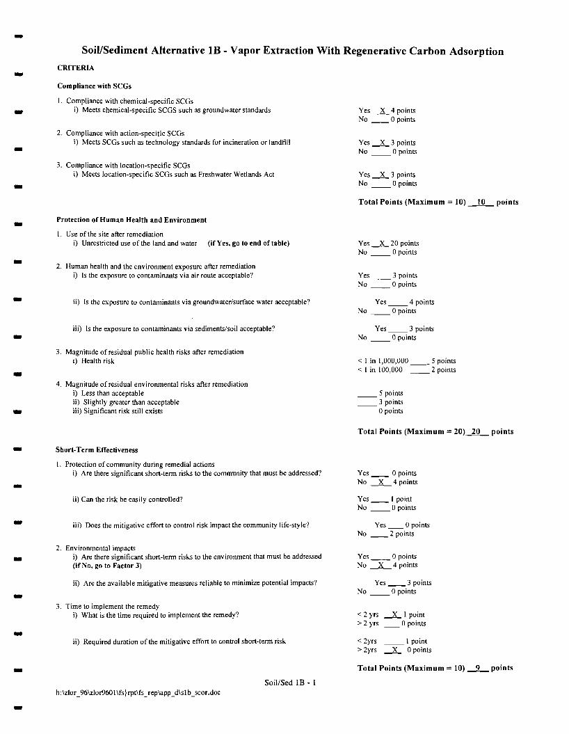
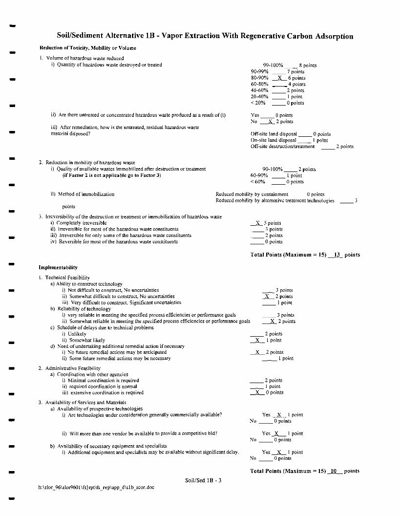
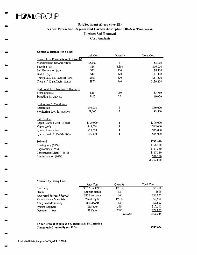
-5.2.2 SoiVSediment Alternative lB-Soil Vapor Extraction/Regenerative Carbon Adsorption
Off-Gas Treatment/Source Area Excavation -Alternative lB also encompasses use of the existing in-situ soil vapor extraction system; however,
off-gas treatment would consist of regenerative carbon adsorption. Elements of the dry well excavation, --
additional subsurface investigation and evaluation and/or modifications to the SVE system as
summarized in Section 5.2.1 above are identical for this alternative.
5.3 Recharge Basin Sediment Remedial Alternatives
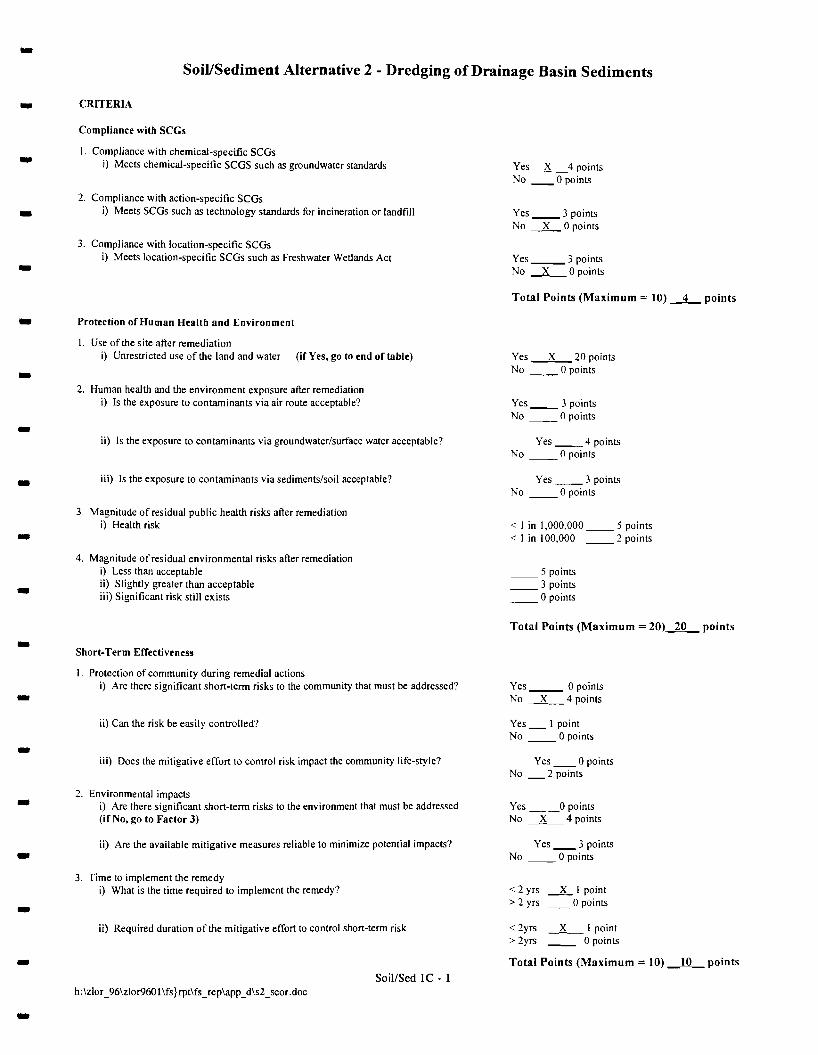
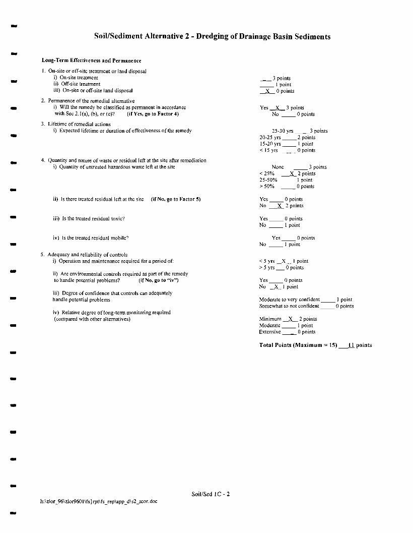
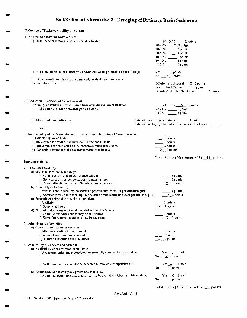
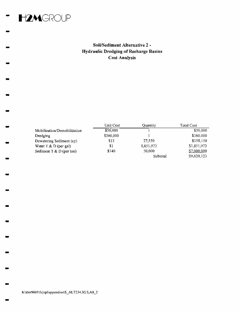
5.3.1 Soil/Sediment Alternative 2 - Dredging of Sediments -Alternative 2 encompasses the removal of the recharge basin sediments by means of a hydraulic
dredge. The depth to which sediment removal is to be performed would need to be established if this-alternative is implemented. For the purpose of this alternative evaluation, an assumed three (3) feet of
sediments will be removed. Dredged soil would be dewatered and transported to a permitted- treatment/disposal facility. Water produced during the dredging operation would either be recharged on
site, discharged to the local sewers, or transported to a permitted treatment/disposal facility, depending - on the chemical and physical characteristics of the water. Following dredging, confirmatory samples
would be collected to document that sediment removal is complete. This remedial alternative would
require use of specialty hydraulic dredging equipment which may not be available locally. The size of -these recharge basins is considered to be relatively small when compared to typical project applications
where sediment removal by hydraulic dredging is more commonly employed, such as in lakes, rivers and -coastal waters. Therefore, dredging equipment that is commercially available would need to be modified
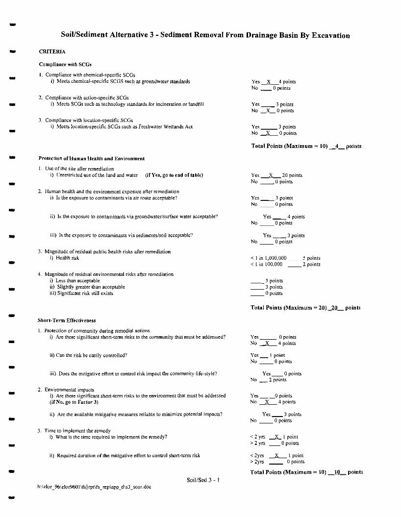
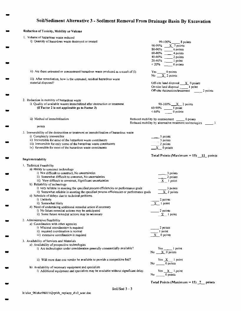
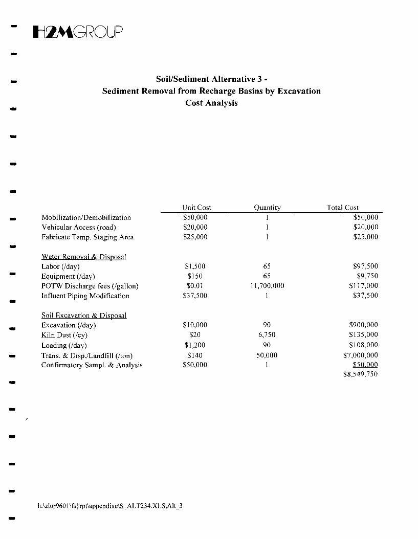
for use at this site. -5.3.2 Soil/Sediment Alternative 3 - Basin Draining and Sediment Excavation - Alternative 3 consists of draining each of the three basins via high capacity pumps and excavating
the top three feet of sediment. The water would be discharged to the municipal sanitary or stormwater
sewer system while the sediments would be transported off-site to a permitted treatment/disposal facility. -In order to remove sediments from the basins, the basins must first be drained. However, since the -
basins are active and continue to receive stormwater runoff, it would not be possible to take all three
basins out of service at the same time unless drainage from rain was diverted elsewhere. If sediment- removal from the basins was done sequentially, one or two basins would be taken out of service while
the other basin(s) would continue to receive runoff. To accommodate this, modifications to the existing - stormwater collection piping would be needed to redirect stormwater flow to one of the alternate basins.
However, because the three basins are interconnected, total isolation of a particular basin to allow for -20-
-Il~GROLIP
- excavation is not possible even if stormwater is diverted away to another basin. Seepage will occur
between the basins since the three basins are underlain and bermed by sand and are at different
elevations, making it difficult to keep one basin from draining to the other. -Prior to the discharge of any standing water from the basins to the local sanitary or stormwater -
sewer system, approvals from Nassau County Department of Public Works (NCDPW) would be
required. In addition, guidance is required from NCDPW as to the maximum allowable discharge rate to - the sewers based on existing sewer capacity. In the development of this remedial alternative, it was
assumed that the standing water from the basins will be acceptable for disposal to the municipal sewers - (based on chemical and physical characteristics, and volume), that a discharge rate of 300 gallons per
minute (gpm) can be accommodated by the sewer lines, and that there will be no time restrictions as to
when the discharge to the sewers may occur. It was estimated based on the size of the basins, assuming -that the basins were full, that there are a total of approximately II million gallons of standing water
requiring discharge to the sewers. -Removal of approximately three (3) feet of sediments from each basin would take place with - bulldozers and excavators. The excavated soil would be transported to a permitted treatment/disposal
facility. The sediment would be prepared for transport (for moisture control) by either the addition of- kiln dust or fly ash. It is estimated that a total of approximately 27,000 cubic yards of soil would be
removed from the three basins (based on an approximate 240,000 square feet of surface area and
assuming a 3 feet excavation), and approximately 50,000 tons of soil will be disposed of off-site. This -estimate of 50,000 tons includes the addition of fly ash or kiln dust for moisture control, which is needed
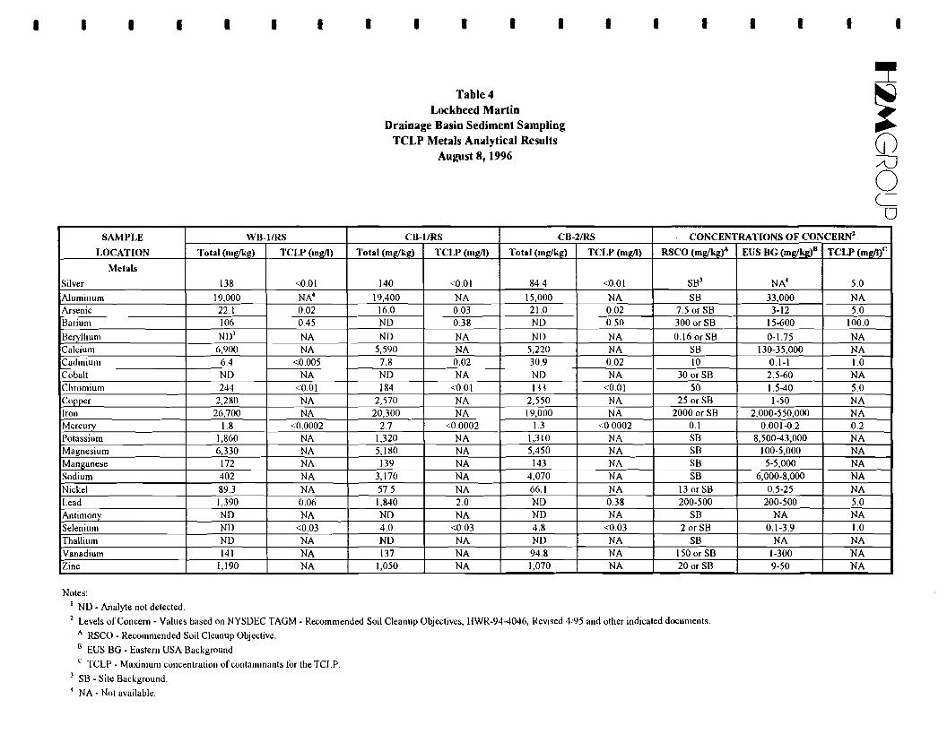
for transport. The TCLP data for sediment samples that were collected on August 8, 1996, one from -each basin, indicate that the sediment in the recharge basins do not exhibit hazardous characteristics and
therefore, can be managed as a non-hazardous waste for disposal. Analytical data for the sediment - samples are included in Table 4 of Appendix G. After excavation, confirmatory soil samples will be
collected to evaluate the effectiveness of the remedial action. Because this work could not be performed - on all basins at the same time, it is estimated that sediment removal from all three recharge basins will
take approximately 6 to 9 months to complete. -The volume of inorganic constituents would be reduced by removmg contaminated sediments.
However, excavating could also release contaminants that are bound in the sediment to groundwater that -are otherwise immobile. -
-21-
-Il~GROUP
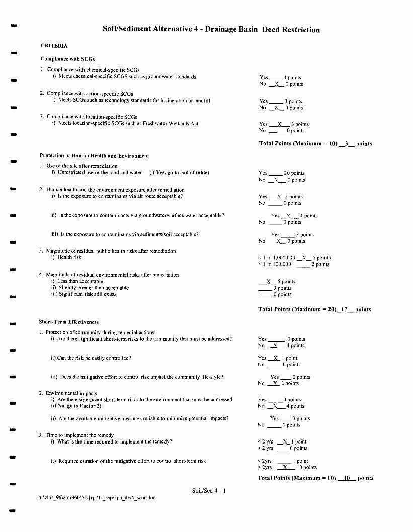
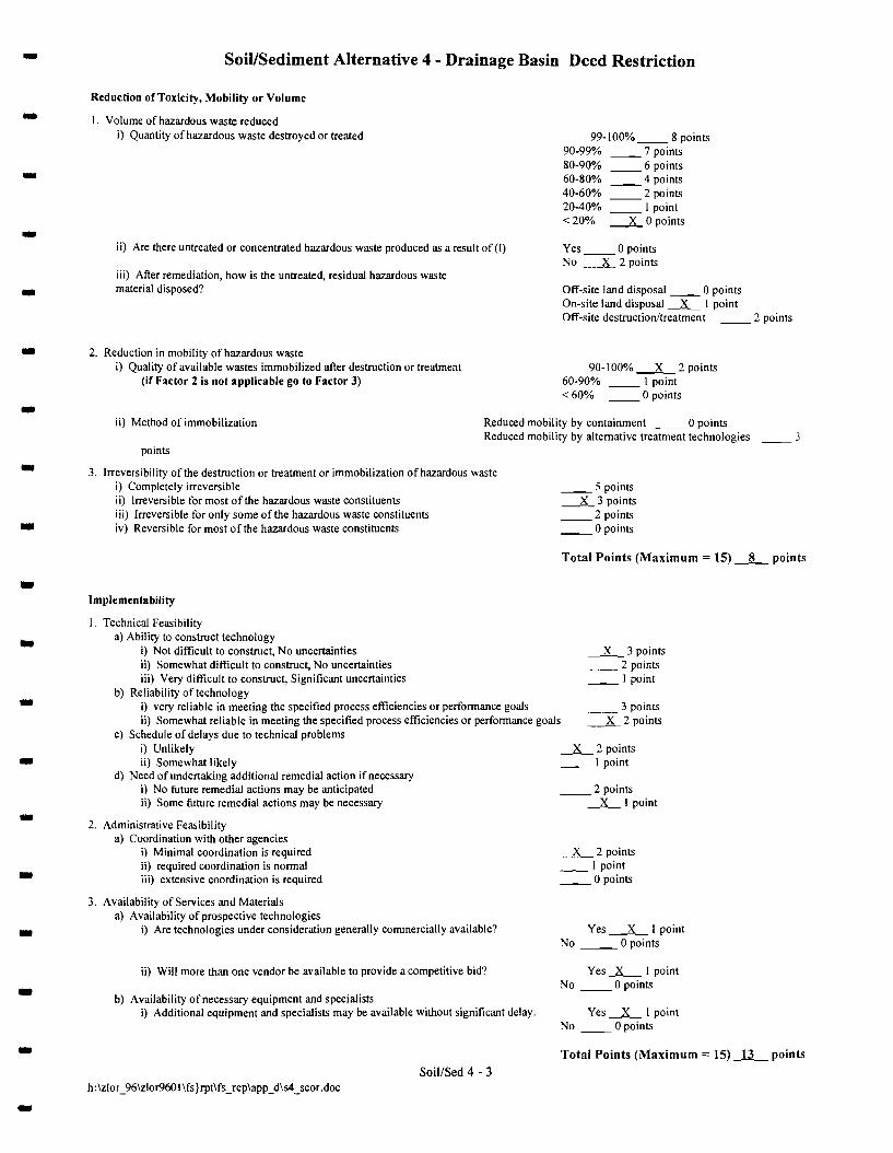
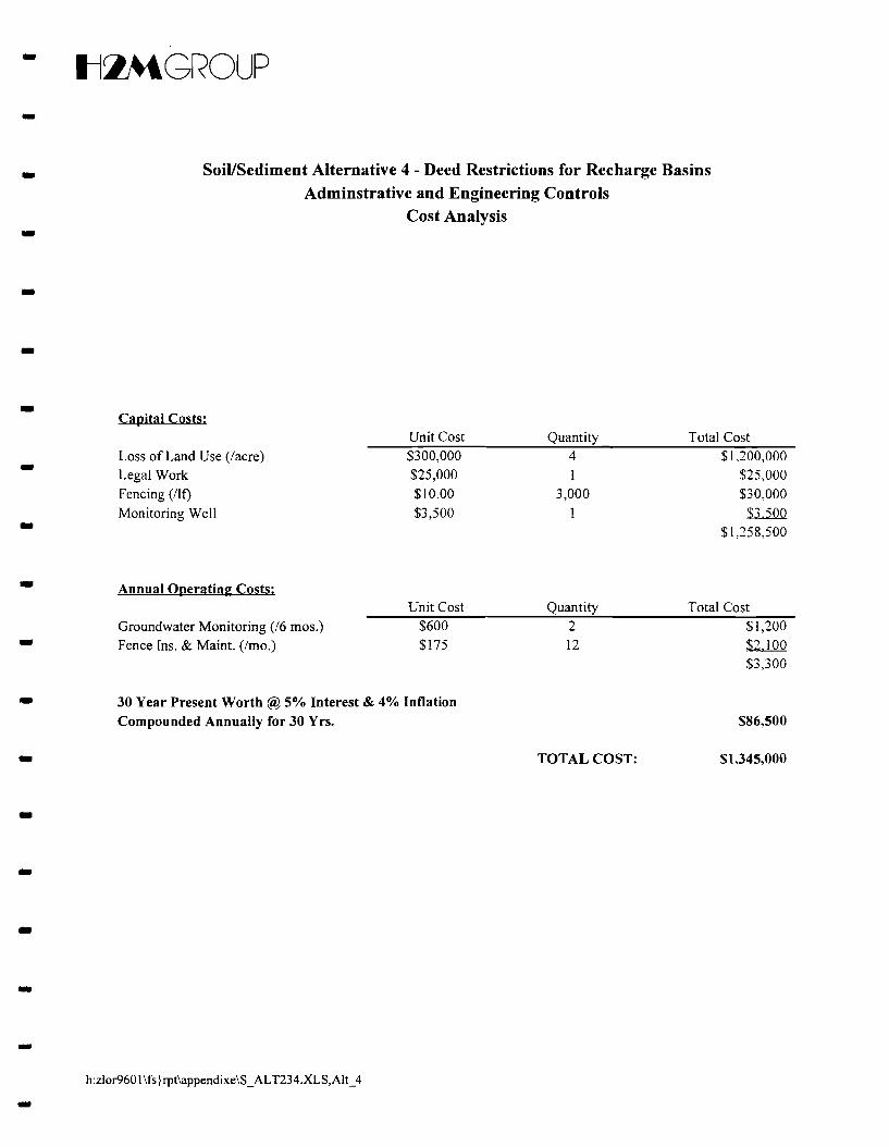
5.3.3 Soil/Sediment Alternative 4 - Deed Restrictions -Alternative 4 consists of a deed restriction or covenant incorporated into a property deed which
limits the use and future development of the property. Under this remedial alternative, the water and -sediments would remain in the recharge basins. A deed restriction will be used to limit access to the
basins and restrict future use of the site. In addition, a fence will be constructed around the entire -~rge basin property to prevent unauthorized access to this are!!:... The fence will be inspected
routinely and repaired as needed to ensure the integrity of the fence. The site will also be posted to - indicate that contaminated materials are present and that trespassing, swimming and fishing are
prohibited. In addition, groundwater monitoring would be performed to evaluate the effectiveness of this
remedy. One new monitoring well (to be completed in the Upper Glacial aquifer) will be installed -downgradient (to the northwest) of the basins. This new well, and one of the existing downgradient
monitoring wells completed in the Lower Glacial aquifer (i.e., 4GL), will be sampled on a semi-annual -basis for two years for metals. Groundwater monitoring will be terminated after establishing four
consecutive rounds (two years) of groundwater data which demonstrates that concentrations are within - the NYS Class GA Groundwater Quality Standards for metals.
- 6.0 Detailed Evaluation of Remedial Alternatives
In this section of the FS, the five (5) groundwater remedial alternatives and the two (2) soil remedial
alternatives are analyzed individually in comparison with specific evaluation criteria required by -NYSDEC. A comparative analysis of the remedial alternatives relative to one another using the same
evaluation criteria is also presented. The criteria evaluated include: -l. Compliance with SCGs 2. Overall protection of human health and environment - 3. Short-term effectiveness
4. Long-term effectiveness 5. Reduction of toxicity, mobility and volume through treatment -6. Implementability
- 7. Cost
Subsections 6.1 and 6.2 presents the individual analysis for each of the five groundwater remedial
alternatives and the two soil remedial alternatives, and Subsections 6.3 and 6.4 presents the comparative -analysis using the scoring system presented in TAGM-HWR-90-4030. Appendix D contains TAGM
HWR-90-4030 scoring results for each alternative. ---
22-
- IlZ\tGROUP - 6.1 Groundwater Remedial Alternative Analysis
The following groundwater remedial alternatives are evaluated individually using the specific
evaluation criteria required by NYSDEC. Alternatives I through 3 all consist of groundwater collection, -groundwater monitoring and reinjection, but with different treatment technology process options.
Groundwater collection will be achieved through the pumpage of high capacity recovery wells. The-pumping rates, locations, and quantity of recovery wells will be detennined with a groundwater flow
model. A discussion of the groundwater flow model is described in section 7.0 of the report. -6.1.1 Groundwater Alternative I - Carbon Adsorption - Alternative I would comply with applicable ARARs and SCGs including groundwater cleanup and
discharge criteria listed in Appendix B. Compliance with these ARARs and SCGs will result in
protection of human health and environment. Achievement of groundwater RAOs would be met through -the short-term effectiveness ofplume migration control and a permanent, long-term reduction in toxicity,
mobility and volume of the constituents of concern at the site. Remedial effectiveness would be -evaluated through a groundwater monitoring program.
- Groundwater treatment would be provided by a series of granular activated carbon adsorption units.
This technology has proven to be very effective in the removal of VOCs from groundwater and is- capable of meeting groundwater discharge criteria. Removal efficiencies greater than 95% can be
expected. Disadvantages of this alternative include off-site regeneration of carbon and relatively high
costs for carbon regeneration. -Specific Alternative I groundwater remedial technologies and process options have already been -
implemented as an IRM. A final remedial measure consisting of Alternative I would easily be
implemented and would be an effective solution..-6.1.2 Groundwater Alternative 2 - Air Stripping - Alternative 2 would comply with applicable ARARs and SCGs for groundwater, but may not
comply with ARARs and SCGs for the air emissions. Achievement of groundwater RAOs would be met
through the short-term effectiveness of plume migration control and a pennanent, long-tenn reduction in -toxicity, mobility and volume of the constituents of concern at the site. Remedial effectiveness would be
evaluated through a groundwater monitoring program. -
-- Groundwater treatment would be provided by air strippers. This technology has proven to be very
effective in the removal of VOCs from groundwater and is capable of meeting groundwater discharge
criteria. Removal efficiencies greater than 95% can be expected. Disadvantages of this alternative are
23-
-ttlMGROUP relatively high energy consumption, potential fouling of the air strippers and air emissions that may -require control. During the initial operation of the treatment system operation, mass loading rates
associated with the emission may warrant control. As the mass loading decreases over time, air emission -control may not be required.
- 6.1.3 Groundwater Alternative 2A - Air Stripping/Yapor Carbon Adsorption
Alternative 2A is the same as Alternative 2 with the addition of vapor phase carbon for emissions - control. It consists of groundwater collection with air stripping for the removal of VOCs. Air emissions
from the air stripper(s) would be treated by vapor carbon adsorption prior to discharge to the atmosphere.
Compared to Alternative 2, this would be further protective of human health and environment. Treated -groundwater would be discharged by reinjection. Groundwater monitoring would be implemented to
evaluate the effectiveness of the alternative. -Carbon adsorption has proven to be very effective in the removal of VOCs in off-gas emissions. - Off-gas removal efficiencies greater than 95% can be expected. Advantages include the ease of
operation, VOC emissions will be minimized, and the probability of a noncompliance event IS- minimized. Disadvantages include the need for off-site disposal/treatment of the spent carbon and the
increased energy consumption necessary to dehumidify the air. -6.1.4 Groundwater Alternative 2B - Air Stripping/Catalytic Incineration Off-Gas Treatment
Alternative 2B is also the same as Alternative 2 with the addition of off-gas treatment consisting of -catalytic incineration. This alternative would be further protective of human health and environment by
treating off-gas emissions prior to discharge to the atmosphere. -Catalytic incineration has proven to be effective in the removal of VOCs in off-gas emissions. Off- gas removal efficiencies greater than 95% can be expected. Advantages include complete destruction of
VOCs. Disadvantages include the potential need for acid gas scrubbers, and higher energy costs. -6.1.5 Groundwater Alternative 3 - UV Oxidation
Alternative 3 consists of groundwater collection with UV Oxidation for the removal of VOCs.-Treated groundwater would be discharged by reinjection. This alternative would be protective of human
health and environment by destroying VOCs and generating by-products of carbon dioxide and water. -UV oxidation has proven to be very effective in the removal of VOCs in groundwater. Removal- efficiencies greater than 95% can be expected. Advantages include complete destruction of VOCs with
no air emissions and ease of implementation. Common limiting steps included the presence of other -24
-
- IlZ\tGROUP
- dissolved materials which are preferentially oxidized. Non-hydrocarbon dissolved contaminants,
including naturally occurring metals (e.g., iron) and minerals, will also be subject to the oxidation
reaction. Other disadvantages include the need for hydrogen peroxide and high energy requirements. -6.2 Soil Remedial Alternatives Analysis -The following soil remedial alternatives are evaluated individually using the specific evaluation
criteria required by NYSDEC. Alternatives IA and IB consist of limited source area excavations and in- situ soil vapor extraction but with different treatment technology process options.
6.2.1 Soil/Sediment Alternative IA - Soil Vapor Extraction/Catalytic Incineration Off-Gas -Treatment/Source Area Excavation
The SVE portion of this remedial alternative has already been implemented as an IRM. Catalytic-incineration technology, which is presently being used, has proven to be very effective in the removal of
VOCs from air and is capable of meeting air emission discharge criteria. Under this remedial alternative, - the SVE treatment system will be supplemented with soil and sludge removal by excavation.
The removal of sludges and soils within and beneath the dry wells will reduce the overall volume of -inorganic and organic constituents. This will supplement the soil vapor extraction treatment by reducing
the mass of organics requiring treatment and thereby reducing the duration of SVE treatment operation. -Further, removal of these areas will reduce the volume of soils impacted with inorganics and eliminate
the potential for future migration. Excavated soil would be disposed of off-site at a permitted facility. -Based on the removal rate of the SVE experienced over the past two years and assuming a non- linear relationship toward the end of the treatment period, we expect that the system will operate for an
additional 2 to 5 years. A request will be made to the NYSDEC to terminate operation of the SVE when
either the soil concentrations meet the Site Specific Soil Cleanup Objectives, or when the SVE system is -no longer effective in removing soil gas, whichever occurs first. This latter point occurs when no further
reduction of soil vapor concentrations are observed over time (i.e., the asymptote of the soil gas removal -vs. time curve). The system will be shut down, allowed to equilibrate, and restarted to determine if
additional soil gas is available for removal. At such time, soil sampling will be conducted and compared - to the site specific soil cleanup objectives to assess the adequacy of the remediation.
--
Alternative lA would comply with applicable ARARs and SCGs including proposed soil cleanup
criteria listed in Appendix B. Compliance with these SCGs will result in protection of human health and
environment. Achievement of soil RAOs would be met through the permanent and long-term reduction
-25 -
- Il~GROUP
- in toxicity and volume of the constituents of concern in soil at the site. Alternative IA would be
effective, easily implemented and a cost-effective remedial measure. -6.2.2 Soil/Sediment Alternative 1B - Soil Vapor Extraction/Carbon Adsorption Off-Gas
Treatment/Source Area Excavation - Alternative IB is similar to Alternative IA except that off-gas emissions would be treated using
regenerative vapor phase carbon. Vapor phase carbon has proven to be very effective in the removal of- VOCs from air and is capable of meeting air emission discharge criteria. Removal efficiencies greater
than 95% can be expected. However, because of the relatively high mass load of VOCs from the SVE
system requiring treatment, the operation and maintenance cost associated with use of vapor phase -carbon for VOC control was determined to be more costly than use of a catalytic incinerator. The soil
and sludge removal program described for Alternative IA above would be identical under this remedial -alternative.
6.3.1 Soil/Sediment Alternative 2 - Dredging of Sediments- Alternative 2, which consists of dredging of the recharge basin sediments by means of a hydraulic
dredge, would comply with applicable ARARs and SCGs including the proposed Site Specific Soil
Cleanup Objectives listed in Appendix B. Achievement of soil RAOs would be met through the -permanent and long-term reduction in toxicity and volume of the constituents of concern in soil at the
site. Although dredging would meet applicable ARARs and SCGs, it has several disadvantages: -• Dredging could exacerbate the contamination problem by mobilizing the currently immobile
inorganic and organic constituents. At present, only VOCs are observed in downgradient- groundwater at concentrations above drinking water standards. Dredging may alter the stability
of complexed inorganics that are adsorbed to the sediment, and help to release the contaminants
to groundwater. -• This alternative would be very difficult to implement primarily because of the relatively small
size of the individual basins. Hydraulic dredging is typically and more easily performed in open -- •
waterways or large sized lagoons. Specialized equipment to accommodate these basins, which may not be available locally, would be needed for this work.
This alternative would not be cost-effective.
6.3.2 Soil/Sediment Alternative 3 - Basin Draining and Sediment Excavation -Alternative 3 consists of draining each of the three basins via high capacity pumps and excavating
the top three feet of sediment. The water would be discharged to the municipal sewer system while the -sediments would be transported to the proper permitted treatment/disposal facility.
-26-
--
Il:lMGROUP
---
Although discussions have been initiated with officials at the Nassau County Department of Publ ic
Works regarding requirements for acceptance of the basin water to the local sewers, according to the
NCDPW, they can not comment on the acceptability of a waste stream until a formal request is made to
the Commissioner requesting an approval for a specific discharge. Since such a request is premature at
this time, the viability of this water management option remains uncertain. If the standing water from
the basins cannot be discharged to the local sewers and an alternate means of water disposal is required,
the overall cost of this alternative may increase significantly.
-----
Similar to Alternative 2 above for hydraulic dredging, Alternative 3 would comply with applicable
ARARs and SCGs including the proposed Site Specific Soil Cleanup Objectives listed in Appendix B.
Achievement of soil RAOs would be met through the permanent and long term reduction in toxicity and
volume of the constituents of concern in soil at the site. Although excavating the sediments would meet
applicable ARARs and SCGs, removal of the sediments could potentially mobilize the currently
immobile inorganic and organic constituent; thatll.rs: bound to the sedime~tsinto g~·ounawafer. At-_.. _--_ .. _--- -~------_._---_._--_. . -------- -
present only VOCs are observed in downgradient groundwater at concentrations above drinking water
standards. Excavation may alter the stability of complexed inorganics that are adsorbed to the sediment
and help to release the contaminants to groundwater. This remedial alternative is not cost-effective.
--
6.3.3 Soil/Sediment Alternative 4 - Deed Restrictions
Under this remedial alternative, the soils and sediments would be left in place in the recharge
basins. The primary constituents of concern are metals in the sediment, attributed to site runoff.
Concentrations in the standing water in the basins are not elevated.
-----
Administrative and engineering controls would be used to limit access to the site. A deed
restriction(s) prohibiting modification to the site without NYSDEC approval will be placed on future
development of the parcel(s) where the recharge basins are located. In addition, a security fence around
the basins will be maintained to prevent trespassing. The fence will be inspected to determine if it is
effective at keeping out trespassers. If the fence is not effective, an appropriate replacement will be
installed or appropriate repairs will be made. The site will also be posted in a highly visible manner
indicating that contaminated materials are present and that trespassing, swimming and fishing are
prohibited. Groundwater monitoring will be performed at two downgradient wells to monitor the
effectiveness of this remedy.
-This alternative would comply with ARARs and SCGs for groundwater since contaminants in the
basins have not impacted groundwater. The primary constituents of concern in the basins are metals, and
- 27
--
~Z\tGROLIP
groundwater downgradient of this area has not shown any indication of metals impact. This alternative
provides short term and long term protectiveness of human health and the environment. Since the
sediments are located under several feet of standing water, the sediments are not accessible to site -workers or to the public, particularly since the basins will be fenced to prevent trespassing. Further,
because this alternative does not involve any sediment removal, this alleviates the concern that -inorganics bound to the sediments may be released to groundwater during or following sediment removal
activities. This alternative can be readily implemented and is the most cost-effective remedy of the-alternatives evaluated for the basins.
- 6.4 Comparative Analysis
6.4.1 Groundwater Remedial Alternatives
The five groundwater remedial alternatives were scored using the criteria established in TAGM-HWR-90-4030. Table 7 summarizes the results of the evaluation. The individual scoring worksheet for
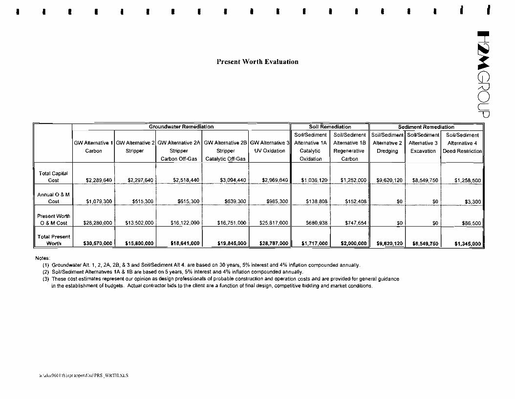
each alternative is contained in Appendix D. -The information on capital and operation & maintenance (0 & M) costs for the five groundwater - remedial alternatives is presented in Appendix E. Some remedial actions have already been
implemented at the site and the costs for these actions have been used in the estimates. TAGM-HWR- 90-4030 suggests that the cost score be developed based on a proportionality approach. The cost score
for each alternative is determined by summing all the alternatives and dividing the sum by the cost of the
alternative. The groundwater remedial alternatives are ranked in descending order: -Alternative 2A - Air Stripping/Carbon Adsorption Off-Gas 82.7 points - Alternative 2B - Air Stripping/Catalytic Incineration Off-Gas Treatment 82.7 points
Alternative 1 - Carbon Adsorption 80.7 points
Alternative 3 - UV Oxidation 80.0 points -Alternative 2 - Air Stripping 77.0 points
- The basis for all groundwater remedial alternatives consists of groundwater collection, treatment,
and reinjection. Groundwater collection wi11 achieve the groundwater RAOs through the short-term - effectiveness of plume migration control and a permanent, long-term reduction in toxicity and volume of
the constituents of concern at the site. Remedial effectiveness would be evaluated through a
groundwater monitoring program. -The significant difference between groundwater remedial alternatives is the selected process option -
for the treatment of groundwater prior to reinjection. The primary treatment technologies, including air
-28-
- Il~GROUP
- stripping, carbon adsorption and UV oxidation, are all capable of reducing constituent of concern
concentrations to acceptable groundwater discharge limitations for reinjection. Removal efficiencies
greater than 95% can be expected. Off-gas treatment technologies including catalytic incineration, -carbon adsorption, and regenerated carbon adsorption are all capable of reducing concentrations of
constituents of concern to acceptable air discharge limits. -As the remedial alternative scoring summary in Table 7 indicates, the scoring for the TAGM-HWR- 90-4030 criteria are very similar for each alternative with the exception of cost. There are, however, a
few notable scoring differences with the implementability criteria of each alternative. The fact that the
selection of a groundwater remedial alternative is based mostly on cost is not surprising since the basis -for each alternative is similar and each alternative is capable ofmeeting applicable ARARs and SCGs. -
6.4.2 Soil Remedial Alternatives
The two soil remedial alternatives were scored using the criteria established in TAGM-HWR-90- 4030. Table 7 summarizes the results of the evaluation. The individual scoring worksheet for each
- alternative is contained in Appendix D.
The information on capital and operation & maintenance (0 & M) costs for the two soil remedial
alternatives is presented in Appendix E. Some remedial actions have already been implemented at the -site and the costs for these actions have been used in the estimates. TAGM-HWR-90-4030 suggests that
the cost score be developed based on a proportionality approach. The cost score for each alternative is-determined by summing all the alternatives and dividing the sum by the cost of the alternative.
- The soil remedial alternatives are ranked in descending order:
Alternative lA - Vapor Extraction/Catalytic Incineration/Source Area Excavation 79.2 points -Alternative 1B - Vapor ExtractionlRegenerative Carbon Adsorption/Source
Area Excavation 77.9 points -The basis for the soil remedial alternatives consists of vapor extraction supplemented by limited - source area excavation. This combination of technologies will achieve the RAO for soil and is capable
of reducing constituent of concern concentrations in soil to below levels proposed in Table 4. The
proposed allowable levels of VOCs in soil represent VOC concentrations which will not contribute to -elevated levels ofVOCs in groundwater according to the NYSDEC TAGM 94-4046 soil leaching model. -
-29 -
- Il:»tGROUP The significant difference between soil remedial alternatives is the selected process option for off-
gas treatment of constituents of concern prior to discharge to the atmosphere. Off-gas treatment
technologies, catalytic incineration and regenerated carbon adsorption, are both capable of reducing -constituent of concern concentrations to acceptable air discharge limitations. Removal efficiencies
greater than 95% can be expected. -As the remedial alternative scoring summary in Table 7 indicates, the scoring for the TAGM-HWR- 90-4030 criteria are very similar for each alternative with the exception of cost. .There is, however, a
minor scoring difference with implementability of the alternatives. The basis for each alternative is
identical and each alternative is capable of meeting applicable ARARs and SCGs. Therefore, deciding -criteria for the soil remedial alternative is the cost. -
The three recharge basin sediment alternatives were scored using the criteria estab Iished in TAGM--
HWR-90-4030. Table 7 summarizes the results of the evaluation. The individual scoring worksheet for
each alternative is contained in Appendix D.
The information on capital and operation & maintenance (0 & M) costs for the three sediment
remedial alternatives is presented in Appendix E. TAGM-HWR-90-4030 suggests that the cost score be -developed based on a proportionality approach. The cost score for each alternative is determined by
summing all the alternatives and dividing the sum by the cost of the alternative. -The recharge basin sediment alternatives are ranked in descending order: -
Alternative 4 - Deed Restrictions 76.5 points
Alternative 3 - Basin Draining and Sediment Excavation 65.3 points -Alternative 2 - Dredging of Sediments 64.0 points
- As the remedial alternative scoring summary in Table 7 indicates, the scoring for the TAGM-HWR
90-4030 criteria are similar for each alternative with the exceptions of cost and implementability. There- is, however, a minor scoring difference based upon the reduction of toxicity, mobility and volume of
hazardous constituents. Each alternative is protective of human health and groundwater. Therefore, the
deciding criteria for a recharge basin sediment remedial alternative is implementability and cost. The -high cost of dredging (present worth of $9.6M) and excavating (present worth of $8.5M), engineering
and institutional difficulties that would be encountered, and potential adverse effects resulting from -release of contaminants to groundwater make the sediment dredging and excavation alternatives less
-30
-
-Il~GROUP
- favorable than the deed restriction, fencing and continued monitoring alternative. This is particularly the
case since removal of the sediments would not necessarily result in a greater degree of human health or
groundwater protection than instituting a deed restriction and constructing a fence to limit access to the -sediments. Therefore, potential risks posed by basin sediments to human receptors can be effectively
mitigated by maintaining present land usage and restricting access. -- 7.0 Remedial Alternative Selection
As stated previously, the purpose of this feasibility study was to select media-specific remedial
alternatives for the protection of human health and the environment through the reduction of material- volume, mobility or volume of groundwater and soil constituents. Action has already been taken to
attain this objective through the IRMs implemented to date. -The information analyzed and presented in this remedial alternative feasibility study has resulted in
identification of a suitable groundwater, soil, and recharge basin sediment remedial alternative for the -site. The highest scoring alternatives identified under the NYSDEC TAGM quantitative protocol are
Alternative 1A for soil, Alternative 2A for groundwater, and Alternative 4 for the recharge basin - sediments.
- 7.1 Selected Soil Remedial Alternative (lA)
The selected soil remedial alternative consists of soil vapor extraction with catalytic incineration
off-gas treatment (see Figure 3) and excavation of three dry wells as a means of source area removal. -The dry well system, consisting of three (3) leaching pools located on the east side of the southeast
corner of the building (where borings SB-1, SB-5, SB-6, and B-16 through B-19 were advanced), will be -excavated. Excavated soil would be transported to a permitted off-site treatment/disposal facility. The
volume of inorganic and organic constituents of concern would be reduced by removing soil containing - these constituents.
- Soil vapor will be collected from a series of vapor extraction wells located within the areas of
highest concentrations of constituents of concern. Soil vapor will be destroyed using catalytic
incineration prior to discharge to the atmosphere. The system will be operated and maintained as -indicated in the IRM Work Plan and all addenda. The selected remedial alternative has been
successfully implemented as an interim remedial measure and has been operating since January 1994. -The existing SVE system will be examined, evaluated and modified or adjusted as needed to maintain
effective operation of the system. --
31 -
-t-i~GROUP
- The selected remedial alternative is capable of meeting the applicable ARARs and SCGs. The mass
ofVOCs in the soil in the area of the dry wells is estimated to have been on the order of 70,000 lbs. This
estimate is based on the average concentrations of total volatile organic compounds detected in samples -collected in the area of the former dry wells that were identified during the RI. Results of the VOC mass
estimation are contained in Appendix A.-To date, based on actual field data, the soil-vapor extraction and treatment system has recovered and - treated approximately 35,000 lbs. of VOCs. In addition, it is estimated that approximately 1,000 pounds
ofVOCs will be removed by the excavation of the three dry wells. Therefore, assuming that the estimate - of 70,000 pounds at one time in the soil is reasonably accurate, it is estimated that approximately 35,000
pounds of VOC still remain in the soil at this time. This estimate of 35,000 lbs. may be conservative
(higher than what is actually present), since other factors (i.e., biodegradation and flushing of soils by -precipitation) that contribute to a lowering of concentrations may have occurred since the RI.
Nevertheless, assuming a 35,000 pound estimate, and using the removal rate experienced over the past --
two years, and assuming a non-linear relationship toward the end of the treatment period, we expect that
the system will be operated for an additional 2 to 5 years.
The objective of the remedial alternative is to achieve the RAOs presented in Table 3, and- specifically, to reduce concentrations of organic compounds in soil to levels protective of groundwater
quality standards. -7.2 Selected Groundwater Remedial Alternative C2A)
The selected groundwater remedial alternative consists of groundwater collection from a series of-extraction and recovery wells. As shown on Figure 4, extracted groundwater will be treated using air
strippers for the removal of VOCs. Air emissions from the air stripper(s) would be treated by vapor - carbon adsorption prior to discharge to the atmosphere. Treated groundwater would be discharged by
reinjection. Groundwater monitoring would be implemented to evaluate the effectiveness of the- alternative. The proposed treatment system will be evaluated after it becomes operational to determine if
additional treatment of the effluent from the air stripper is needed.-The selected remedial alternative is capable of meeting the applicable ARARs and SCGs. To date,
the groundwater treatment system has recovered and treated over 840 million gallons of water. The-objective of the remedial alternative is to achieve the RAOs presented in Table 3 and specifically, to
prevent constituent plume migration and reduce organic compound concentrations in groundwater.--
32-
- Il~GROUP
- The selected remedial alternative targets the Upper Glacial aquifer, and the upper and intermediate
zones of the Magothy aquifer for hydraulic control by pumping with treatment. This provides capture
(hydraulic control) of contaminated groundwater down to a depth of approximately 270 ft. below grade. -Concentrations of contaminants present in the lower Magothy aquifer are typically an order of magnitude
lower than in the shallower aquifer zones and are expected to decrease by natural attenuation because the -proposed groundwater extraction system will interdict further downward migration from the source area.
Additionally, pumping from the lower Magothy aquifer could pull much higher concentrations of- contaminants from shallower zones down to the lower Magothy. Therefore, since the indirect benefits of
interdicting contaminant migration are expected to yield improved water quality in the lower Magothy - aquifer, active pumping of the lower Magothy is not proposed at this time.
Pumping and water quality data will be monitored to determine the effects of the extraction system -on contamination in the lower Magothy aquifer. After the selected remedial alternative becomes
operational, it will be evaluated to determine if additional remedial alternatives for the lower Magothy -need to be implemented. This issue will also be addressed as part of the Operable Unit 2 Remedial
Investigation I Feasibility Study. -Over time, the selected remedial alternative will be evaluated by sampling both on-site and off-site - monitoring wells to determine its ability to provide hydraulic control, to meet discharge standards, and to
reduce on-site groundwater concentrations to the remedial action objectives. -7.2.1 Groundwater Flow Model
A groundwater flow model was used to evaluate and design an effective extraction system. A-numerical mathematical model was used to simulate the groundwater flow conditions at the site and
predict the best location and pumping rates for groundwater extraction wells. Simulation of groundwater--
flow in the vicinity of the site was accomplished using the U.S. Geological Survey's MODFLOW code
(McDonald and Harbaugh, 1988). This is a U.S. EPA-endorsed finite difference groundwater model for
simulating hydraulic heads over a specified model domain. Following calibration of MODFLOW, a path
line analysis was undertaken using PATH3D to delineate capture zones around the pumping centers.
This was accomplished by placing particles in cells upgradient of the pumping centers of interest and -running forward simulations under pumping conditions. Detailed descriptions of the numerical
implementation, code verification, and model results are included in Appendix F. -The model-predicted potentiometric surface compared favorably with the actual potentiometric -
-surface. This means that the model effectively simulates the current groundwater flow conditions at the
site. After calibration of the potentiometric surface, the model was then used to predict the effect of
33-
-Il~GROUP
- pumping groundwater from varIOUS extraction well configurations. Pumping rates in eXlstmg and
proposed wells were progressively modified until the extraction network most effectively captured the
on-site VOC plume in model layers 1,2, and 3. Appendix F Figures 3.1, 3.2, and 3.3 show the predicted -containment model and capture zone for layers I, 2, and 3 respectively. These figures show that five
pumping wells will be needed to effectively collect the VOC plume in model layers I, 2, and 3. -- 7.2.2 Groundwater Collection System
Based on existing hydraulic data, and utilizing the predictions from the groundwater model
described above, it is estimated that a total of five (5) extraction wells will be operated across the site - extracting 1,800 gpm. The pumping wells to be used for groundwater collection include EW3 and RW3
pumping at 300 gpm each and EWI, RWl, and RWIA pumping at 400 gpm each. Wells EWl, RWI,
and EW3 have been installed and are being operated as part of the IRM. These wells are connected via -an existing 12-inch forced main. The extraction system will be expanded by the installation of well RW3
near the western boundary of the site and RWIA as a deeper well adjacent to RWI. The groundwater -collection system will be evaluated after it becomes operational to determine if additional extraction
wells are needed and if so, the extraction system will be modified. A process flow schematic showing - the conceptual layout of the groundwater extraction and treatment system is shown in Figure 4.
- Model layers 1, 2, and 3 will be targeted for control for the following reasons:
• Based upon the RI data the majority of the contaminated groundwater is present on-site in the Upper and Intermediate Magothy Aquifer. -
• Typically, the concentration of contaminants in the Lower Magothy are significantly lower then
in the Upper and Intermediate Magothy. -• The injection and extraction wells of the non-contact cooling system are screened in model
layers 2 and 3. The historic extraction and injection of water into model layers 2 and 3 - encouraged contaminant transport/migration into these layers.
7.3 Selected Recharge Basin Remedial Alternative (4) -The selected alternative for the recharge basin sediments consists of a deed restriction which limits
the use of the basins. A covenant precluding the removal or filling of the recharge basins would prevent -unacceptable contact with the recharge basin sediments. Further controls such as a fence will be
maintained around the basins to further restrict access to the basins. In addition, the site will be posted to - indicate that contaminated materials are present and that trespassing, swimming and fishing are
prohibited. Groundwater monitoring would be implemented to evaluate the effectiveness of this remedy. --
34 -
------------------
Il~GROUP
This remedy provides for short-term and long-term protection of human health and the environment.
The quantitative risk assessment for ingestion, dermal contact, and soil inhalation of the recharge basin
sediments identified potential sub-chronic, chronic, and carcinogenic risks associated with ingestion and
dermal contact. Potential risks would be present only if sediments from the recharge basins become
accessible for contact. Given current usage of the basins, the sediments contained in them are on the
bottom under as much as twenty feet of water. Thus the sediments are not exposed or accessible to
human contact. Provided that the basins continue to be used as recharge basins and the basins remain
restricted by means of fencing, the sediments contained in the basins will not become accessible for
human receptor contact. Therefore, potential risks posed by ingestion and/or dermal contact with
contaminated sediments can effectively be avoided.
In evaluating cost benefits between the deed restriction alternative (present worth of $1.3 M), the
sediment dredging (present worth of $9.6M), and sediment excavation (present worth $8.5M), there is an
added cost of approximately $8.3M associated with the hydraulic dredging alternative and an added cost
of $7.2M associated with the sediment excavation alternative. However, based on the cost for sediment
dredging or excavation, and considering that a deed restriction would also be sufficiently protective of
human health and the groundwater, with a lower likelihood for groundwater impact to occur, a deed
restriction, together with fencing, posting of signs and continued groundwater monitoring is the
recommended remedy for the recharge basins.
35 -
-Il~GROUP
-References
-1. Remedial Investigation and Feasibility Study Work Plan, Unisys Corporation, September 1993.
2. Phase I Remedial Investigation Report, Lockheed Martin Tactical Defense Systems Division, -December 1996.
3. Supplement~l Remedial Investigation Report, Lockheed Martin Tactical Defense Systems Division, -December 1996.
4. Effect of Urban Stormwater Runoffon Ground Water Beneath Recharge Basins on Long Island, New - York, Ku, H. and D. L. Simmons, United States Geological Survey Water-Resources Investigations Report, 85-4088, 1986. - 5. Guidance for Conducting Remedial Investigations and Feasibility Studies Under CERCLA - Interim Final, USEPA, October 1988. - 6. Presumptive Remedies: Policy and Procedures, USEPA, September 1993.
7. Soil Screening Guidance, USEPA, December 1994. -8. TAGM # HWR-90-4030, Selection OfRemedial Actions At Inactive Hazardous Waste Sites, NYDEC,
May 1990. -9. TAGM # HWR-94-4046, Determination ofSoil Cleanup Objectives and Cleanup Level,. NYSDEC,
1994.-10. Element Concentrations in Soils and Other Surficial Materials ofthe Conterminous United States,
H.T. Shacklette and J.G. Boerngen, United States Geological Survey, Professional Paper 1270. ------
36 -
..I L
,, ...
f
L.
L L L L L
• TABLESL.
L
- t-i:lMGROUP Table 1 -
RI Groundwater Quality Evaluation - Lockheed Martin Great Neck, NY
Minumum to Number of- NYSCompound Samples AboveMaximum MCLs
Diethylphthalate ND to 11 0 1 501 - II--..:.......,,---------t·····..···..·· ················~···· ..· .It-D_i_-n_-b_u_ty::....l-'-p_hth_al_at_e --+ ~p..~~.9.:.~.!. 1. 9. 1. ?g .Butylbenzylphthalate ND to 0.71 [ 0 ~ 50Heptachlor ·N:r)·t~··O·.·03"4T ..r .. ·O····· ···..···········T ·(5:"4··..·····..····· - ND Not detected J Value is estimated - compound detected below the practical quantitation limit. B Compound detected in either the field blank, trip blank and/or laboratory blank -
-------
TABLE1.xLS -
I I I I I I I I I I I I I I I I I I I
~ Table 2A
RI Soil Quality Evaluation - Inorganics !Loral Defense Systems East Great Neck, NY (j)
AJIn i':::==
Compound
RI
Background Sample
Ory Well Soil Sample Results TAGM 94-4046
Minumum to Average Samples Above Background, Eastern US NYS Recomended
Maximum Concentration NYSOEC Soil Cleanup Objectives, Background Soil Clean-Up
Concentration and Eastern US Background Objectives
I~
Miligrams per Kilogram
Aluminum
I Arsenic Barium Beryllium
I Cadmium Chromium
"Cobalt
ILead Magnesium
IManganese Mercury
Nickel
I Selenium Silver
I Vanadium Zinc
Cyanide
21,100 1,270 to 20,600i 5247 ~ - - 33,000 i SB
:::::::::::::::~:·I:::::::::::: :::::I?T~?::~:;~::::::r.:::::::::::::::L2:::::::::::::::r.:::::::::::::::::::::::::::::::::::::::::::~::~:~::::::::::::::::::::::::::::::::::::::::::: :::::::::::~:~:~I:::::::r:::::::::::?::~::~:~:~~:::::::::::: 63.9 6.9 to 491! 80 i - - 15-600! 300 or SB .................................... . ~ ( : .
O.77B NO to 2.6 ~ 0.62 i G(2.6) 0-1.75 ! 0.16 or SB
::::::::::::::N~:::::::::::::: ::::::B.~:~~:~j;:?::::I::::::::::::::~;~::::::::::::::T:::::::::::::::::::::::::::::::::::::9(?~:;2).::::::::::::::::::::::::::::::::::::::::::::::::g:)~:C::::::r:::::::::::::::::j§::::::::::::::::::: 23.9 NO to 6701 i 81! 0(55), G(670) 1.5-40! 50
:::::::::::::::?':$.::::::::::::::: ·:::::::L:~::~?::?I~::::I:::::::::::::J~::::::::::::::I:::::::::::::::::::::::::::::::::::::9(~~:;~).:::::::::::::::::::::::::::::::::::::: :::::::I}~:~Q:::::::r::::::::::::~:g::~~::$.:$.::::::::::::: 82.3 2.21 to 9,7801 ! 1041! G(9,780) 200-500! 400* ..........................................................................( ( : . 2290 400 to 15,300 i 2295 1 G(15,300) 100-5000 1 SB
::::::::::::::~f?:::::::::::::: :::::::~2J:~?::?~:~::::T::::::::::::::n:?:::::::::::::T::::::::::::::::::::::::::::::::::::::::::~::~:~::::::::::::::::::::::::::::::::::::::::::: :::::}9.~~§Q§::::r:::::::::::::::::::~$.:::::::::::::::::::: 0.06B NO to 23.1 i 2.8 ! G(23.1), C(0.52), 0(1.6), 1(2.2) 0.001-0.2 ! 0.1 ..........................................................................( ·····c················································ : . 28.5 12.6 to 679 i 80! G(679) 0.5-25 i 13 or SB
:::::::::::~;:~:~~::::::::::: ·:::::::Np.::~:?::?:;~::::::T::::::::::::J;~::::::::::::::T::::::::::::::::::::::::::::::::::::::9.:(2;:~):::::::::::::::::::::::::::::::::::::::: ::::::::~:;F~:;~::::::r:::::::::::::?::?i::~~:::::::::::::: NO NO to 6.71 1 1.2 i -- - 0.01 - 5.0 ! SB
::::::::::>~I::::::::::: .::::::B.p.:~~)~;:~:::::I::::::::::::JC::::::::::::I:::::::::::::::::::::::::::::::::::::::::::~::~:~::::::::::::::::::::::::::::::::::::::::::: ::::::::::~:~~:g§:::::::r:::::::::::(j~:?i::~~::::::::::: 55.7 ND to 4,350 1 52 1 G(4,350), C(95), 0(140), H(95), 1(416) 9-50 1 20 or SB ......................................................····················c································· ( : . NO NO to 11.3! 3.6 1 - - - NA ! Site-Specific
NO Not detected
J Value is estimated - compound detected below the practical quantitation limit.
8 Compound detected in either the field blank, trip blank and/or laboratory blank
S8 Site 8ackground A= 815(10-12'),8= 815(18-20'), C= 816(13-15'),0=816(19-21'), E= 817(16-18'), F= 817(18-20'), G= 818(6-8') H= 818(22-24'),1= 819(6-8'), J= 819(18-20') • TheEPA's Interim Lead Hazard Guidance establishes a residential screening level of 400 ppm.
-Il~GROUP
Table 2B- RI Soil Quality Evaluation - Organics Loc:kheed Martin Great Neck, NY
--------------
Compound
1
1
RI
BackgroundSample
Dry Well Soil Sample Results Site-Specific
Soil Clean-UpObjectives(B)
Minumum to Number of Maximum Samples Above
Concentration Cleanup Objective
AverageConcentration
Miligrams per Kilogram 1,2 -Dichloroethene (total) _..~.!? _ ~.!?.!~ ~.?.9.:!..._.•............_ g __ __1.~.:~~~ _ _~..:~~? . If=1;,:;,1~,.:..1_- ..:.T.:..:ri.:..ch.:..:l.:..oroe;.;;.,;;,t;,;;h.:..:an;,;;e;".,.-~ ~.!? _ ~~..!?..§.?.L l _ g _._.- L--?}-~~_ _.._~:~.? .Trichloroethene ND ND to 7,800! c, E, G, H, 1 ! 834.7 1.89
- ND Not detected J Value is estimated .. compound detected below the practical quantitation limit B Compound detected in erther the field blank, trip blank and/or laboratory blank
NO Not detected J Value is estimated· compound detected below the practical quantitation limit. B Compound detected in e~her the field blank, trip blank and/or laboratory blank - K= EB1, Lz EB2. M= EB3, N= EB4, 0= CB1, P= CB2, Q= CB3, R= CB4. 5= WB1, T= WB2 (see Figure 6-1 in the RI report)
(a)= Developed in accordance with NYSOEC TAGM HWR 94-4046.
-- TABLE2C.xLS
I I I I I I I I I I I I I I I I I I• ~ Table 2D
RI Recharge Basin Sediment Evaluation - Inorganics Lockheed Martin !Great Neck, NY (j)
A:J
Compound
RI Background
Sample
Recharge Basin Sediment Samples TAGM 94-4046 Minumum to
Maximum
Concentration
Samples Above Background, I NYSOEC Soil Cleanup Objectives,
and Eastern US Background
Average Concentration
Eastern US Background
INYS Recomended Soil Clean-Up
Objectives Miligrams per Kilogram
Aluminum
Arsenic Barium
BerylliumCadmium
Chromium
ICobalt Lead
Magnesium
Manganese Mercury
~ickel Selenium
Silver
Vanadium Zinc
Cyanide I
21,100 5,140 to 18,500l - - i 7817.0 33,000 i SB
50.9 17.5-256 ~ - - - j 103.4 1-300 i 150 or SB · ·55·.'7 · i·o7~i'::770 ·..r ·K·j~:..~~(·i{..O~..p·: ..Q:..~ ..S·:..T r..· ·6·5·6·.·6 ·.. · ·..9:5·0· · r 20..~·~..SB ..
~ , ~ .. NO ND-29.2 1 - - - 1 8.5 NA ~ Site-Specific
o C U
NO Not detected J Value is estimated - compound detected below the practical quantitation limit. B Compound detected in either the field blank, trip blank and/or laboratory blank SB Site Background K= EB1, L= EB2, M= EB3, N= EB4, 0= CB1, p= CB2, Q= CB3, R= CB4, s= WB1, T= WB2 (see Figure 6-1 in the RI report)
* TheEPA's Interim Lead Hazard Guidance establishes a residential screening level of 400 ppm.
TABLE2D.XLS
- t-i~GROLIP Table 3 - Remedial Action Objectives
- Lockheed Martin Great Neck, NY
- Environmental Media
Remedial Action Objectives (RAOs)
--
Groundwater Human Health Prevent ingestion ofwater having concentrations in excess ofthe following:
Groundwater Protection Prevent migration of constituents that would impact groundwater. The constituents and corresponding cleanup goals are as follows:
Table 5 Remedial Technology Types and Process Options
Lockheed Martin Great Neck, NY
Environmental Remedial Action Objectives General Response Actions Remedial Technology Types Media (RAOs) (GRAs)
GrOlllldwater Human Health No Action! Institutional Actions No ActionlInstitutional Options
1. No Action Prevent ingestion ofgroundwater having I. Deed Restrictions concentrations in excess ofthe following: 2. Alternate Water Supply 2. Groundwater Monitoring
3. Monitoring Constituent Concentration
Containment Actions Containment Technologies 1,2-DCE S ugIL TCE S ugIL 1. Containment I. Vertical Barriers PCE S ugIL 2. Horizontal Barriers Freon 113 S ugIL
Restore aquifer at downgradient property 1. CollectionrfreatmentJDischarge I. Groundwater Collection line to the following: 2. In-Situ Groundwater Treatment
3. Water Supply Treatment Treatment Technologies Constituent Concentration
1,2-DCE S ugIL I. Physical Treatment TCE S ugIL 2. Chemical Treatment PCE S ugIL 3. In-situ Treatment
4. Off-Gas Treatment Freon 113 S ugIL
Disposal Technologies
I. Discharge to POTW 2. Discharge to Surface Waters 3. Reinjection
Air Stripping, Adsorption UV Oxidation Catalytic Degradation, Air Spargingl Vapor Extraction, Biorernediation Adsorption, Incineration
After Treatment After Treatment After Treatment
~
~ N o l U
labk5.doc
I I I I I I I I I I I I I I I I I I• ~
Table 5 (Continued) Remedial Technology Types and Process Options
Lockheed Martin ~ Great Neck, NY :::u o c
uEnvironmental Media Remedial Adlon Objectives (RAOs) General Response Actions (GRAs) Remedial Technolol!v Types I Process Options
Soil Environmental Protection No Action! Institutional Actions No Actionllnstitutional Options
Prevent migration of constituents that I. No Action I. Deed Restrictions would impact groundwater. 2. Monitoring The constituents and corresponding cleanup goals are as follows: Containment Actions Containment Teclmologies
Constituent Concentration I. Containment I. Vertical Barriers Slurry Walls, Sheet Piling 2. Horizontal Barriers Liners, Grout injection
Human Health Prevent ingestion and dermal contact ofsoil \. ExcavationffreatmentlDisposal \. Excavation Solids Excavation particles having concentrations in excess of the following:
GU GLACIAL UPPER (90- 115 ft bg) GL GLACIAL LOWER (125-185 ft bg) MI MAGOTHY INTERMEDIATE (210-250 ft bg) ML MAGOTHY LOWER (300-400 ft bg) "RW RECOVERY WELL EW EXTRACTION WELL OW DIFFUSION WELL
- The mass of VOCs in groundwater under the site was estimated based on RI groundwater
- sampling results. The aquifer was subdivided in two layers and the average total volatile organic
compound concentration was calculated for each layer. Layer A extends from the top of the water table
(elevation 42 feet ms\) to the bottom of the lowest extraction well (elevation -140 feet msl) and is 180
- feet thick. Layer B extends from the bottom of the lowest extraction well to the top of the Raritan Clay
(elevation -350 feet ms\) and is 210 feet thick. Results of the VOC mass estimation are contained in
- Appendix A and are summarized below.
--
Layer Average VOC
Concentration (ug/kg) Groundwater Volume (gal) TVOC Mass (lb) A 1,000 1.4 x 10⁹ 11,700
B 260 1.7 x 10⁹ 3,700
Total 3.1 x 10⁹ 15,400
-----------
The quantities given above are only estimates and several assumptions were made in order to
calculate the mass of TVOCs. These assumptions include the porosity is 0.25 and the RI analytical data
is representative of average current groundwater conditions. These quantities will be reevaluated as
more data becomes available.
Layer A
Top elevation = 40 msl Bottom elevation = -140 msl Thickness = 180 ft Area = 98 acres = 4.27 x 106 ft 2 Volume of Water = (180 ft.)(4.27 x 106
= 1.4 x 10⁹ gal
Average cone. = 1,000 ug/L
ft 2 )(.25 porosity)(7.48 gal/ft3)
Mass VOCs = (1,000 ugIL)(1.4 X 10⁹ gal)(3.785 Llgal)(lO-9 kg/ug) = 5,300 kg = 11,7001b
Layer B
Top elevation = -140 msl Average cone. = 260 ug/L Bottom elevation = -350 msl Thickness = 210ft Area = 98 acres = 4.27 x 106 ft 2 Volume of Water = (210 ft)(4.27 x 106 ft2 )(.25 porosity)(7.48 gal/ft3
)
= 1.7 x 10⁹ gal Mass VOCs = (260 ugIL)(1.7 x 10⁹gal)(3.785L1gal)(lO-9 ug/kg)
AVERAGE CONCENTRATION OF TVOC IN LAYER A WELLS ~ NOVEMBER 1994
>aQITOM
2J 2J
7J
Notes: All concentrations in ppb, Other = 1,2-Dichloroethane, 1, l-Dichloroethane, Dichlorodifluoromethane, Chloroform, Chlorobenzene, benzene, Xylene, Ethylbenzene J = Parameter was determined to be present below the method detection limit. The concentration is an estimated value. -- = Not detected. DCE = Dichloroethene, TCE = Trichloroethene, PCE = Tetrachloroethene, TCA = Trichloroethane.
~ /\Jo C U
I I I I I I I I I I I I I I I I I I• ~
AVERAGE CONCENTRATION OF TVOC IN LAYER B WELLS NOVEMBER 1994
2ML I 447 I 125.69 I -321.31 1··2'Mr-·····l"···_······393····""_·'l"·,········.. ·········1'3·~i'8·5'··'··_ ..·,·· ..····r···········'·'=:n5·9'~1'5-"" ..·"
-~ ~~~~l1~~!~;~~"~~=+m Notes: All concentrations in ppb, Other = 1.2-Dichloroethane, 1,1-Dichloroethane, Dichlorodifluoromethane, Chloroform, Chlorobenzene, benzene, Xylene, Ethylbenzene J = Parameter was determined to be present below the method detection limit. The concentration is an estimated value. -- = Not detected. DCE = Dichloroethene, TCE = Trichloroethene. PCE = Tetrachloroethene, TCA = Trichloroethane.
:::cJ o C U
-Il~GROUP
- VOC MASS CALCULATION FOR SOIL
---
Available data was used to estimate the mass of VOCs adsorbed to impacted soils located in the
vicinity of the former dry wells. Data utilized included soil samples collected prior to the RI in 1988,
1990, and 1991 and soil samples collected during the RI. Total VOC (TVOC) analytical results were
plotted on a cross section in order to estimate the volume of soil impacted by VOCs. Review of the
plotted data indicated an area of relatively high VOCs in the immediate vicinity of the dry wells (area I)
and a much larger area (area 2) with lower VOC concentrations surrounding area I. Results of the VOC
mass estimation are summarized below.
--- The quantities given above are only estimates and several assumptions were made in order to
calculate the mass of TVOCs. These assumptions include the area of impacted soil is cylindrical in
shape with a diameter of 125 feet in Area 1 and 225 feet in Area 2; the analytical data is representative of -average current soil conditions, and the zone of impacted soil does not extend more than 10 feet below
the groundwater table. These quantities will be reevaluated as more data becomes available. -- Area 1
-Soil volume = 1t(63 fti(30 ft)
= 374,069 ft3 = 13,900yd3
3Soil mass = 374,069 ft3 x 110 Ib/ft x 1 Ib./2.2 kg = 18.7 x 10⁶ kg- = 41 X 106 Ib
TVOC mass = 18.7 x 106 kg X 10.6 kg/mg x 1,250 mg/kg = 23,400 kg - = 52,000 Ib
Soil mass = 3.24 x 106 ft3 x 110 Ib/ft3 x 1 Ib/2.2 kg - = 1.62 x 10⁸ kg = 3.56 x 10⁸ 1b
8
- TVOC mass = 1.62 x 10= 7,200 kg = 18,000 Ib
Estimated Total VOCs in Soil =--------------
kg X 10-6 kg/mg x 45 mg/kg
Approximately 70,000 Ib
I I I I I I I I I I I I I I I I I I I
Pre RI Soil Sampling Data Great Neck, NY ~
Vapor I Boring I I I Sample I PHC I Total I Total I Total Boring I Well Depth (ft.) Date Drilled Sample Number Depth (ft) (ppm) VOCs SVOCs Pest./PCBs I Parameters ~
:~ ~~~13~§f[iH:EL~=~-==:::=~~ I·......· :: .I ·· .. ·· ·:: · l·.. ··~?~·~·: ..P..~·~: ~·:!·~·I~ ... B-7 no 30 4/11/88 B-7 I 30-32 i
1----1..- - _ _ · · · · ··· · ·..· ··· ··..1..•·•· ·• · 1 · B 8 _.. ~.? 1 ~.9. ~.(~ ~.!.~~ §..:~ B-9 no I 32 I 4/12/88 I B...9 ,
~3LTH~Iif£::~Lr--B-12 no i 30 i 3/31/88 I B-12
B-13 ~.=:~.~.::·::~?..:·:·::......].:......~:::~.::::::::~.9·~:·:: ..~::: ..:·:.L~:: ...·:~i.:~·:i!.:~~ ..~~·]:: ..·:::::::::::::~.:::.~:;'''i'3 8-14 no! 30 I 4/12/88 I B 1 ·· -_..·· · _···· t ··..· _·· ·· · · ·l ·· ·· ·· ·..·· ..·t ·..· ·· ··• , SVB1 no I 50 i 6/12/90 I _... I -- I..__·__·..·_·, · r SVB2 VW1 91 i 6/14/90 SVB2-50-51.5! 50-51.5 I
I",. ".." ,.,'~- "",,,..,, ..j,. """, ~""", ''',·""",1, · ·..· :~·, "" .."..,1, , ::"" .1 " "..~.?,~,~ , " ",,' ,. SVB5 80 I 6/21/90 i SVB5-70-71.5 i 70-7 . vocsII--+---------j ·· ·..· · · · ·t ·..·..· · · ·· t·· ·..· · · '1 · ·..·..• ·..·1 .. SVB5 " 80 I 6/21/90 I SVB5-80-81.5 I 80-81.5 I -- vocs
~~:~ ---~-RFi-~~9.:.r=~3:=r==~~=F-=l::--j-::- --I-_-:::-+~f":!N:~D) SVB8 I no 25! 6/25/90 i -- i ...- i -- ! -- i -- I -- I NA
note: all results in ppb unless otherwise noted, -- not analyzed, * detected in blank or below mdl, NO not detested, + data not available. SOILBORXLS
I I I I I I I I I I I I I I I I I I I
Pre RI Soil Sampling Data Great Neck, NY ~
Vapor I Boring I I I Sample I PHC I Total I ITotal Total Boring I Well Depth (ft.) Date Drilled Sample Number Depth (ft) (ppm) VOCs SVOCs Pest./PCBs I Parameters ~
/\Ji;~9~~-l·I~~II~~~~=I~~ oSVB11 VW8 90 7/24/91 SVB112022 20..22 I -- NO I -- -- telvoes
~~~jl::I~~I:~I~~~~~ CU
SVB13 VW9 90 7/26/91 SVB132022 20..22 I -- , * I -- I -- lelvoes
~~m~~~t~-ml~~~~ SVB17 " ~Q. "".L ~!.??!.,~ ..~"" "".L ".".,.?y~ .:~"? "" " ""~g.=.~,? " ,,!..,,,, ,,=,:"" "l ~..~.q~.9..~q ,J"" " =,= L ""'''==,.".".."....1 ,,,,,, ~,~, ~,?.~: ,,,, ,.. SVB17 " 90 i 8/22/91 ! SVB-17B i 20-22 I -- I 1,899,000 ! -- i -- I tel voes
note: all results in ppb unless otherwise noted, -- not analyzed, * detected in blank or below mdl, NO not detested, + data not available. SOILBOR.XLS
I I I I I I I I I I I I I I I I I I I
Pre RI Soil Sampling Data Great Neck, NY ~
Total Total TotalVapor I Boring I I I Sample I PHC VOCs SVOCsBoring I Well Depth (ft.) Date Drilled Sample Number Depth (ft) (ppm) Pest./PCBs Parameters
SVB17 " I 90 i 8/22/91 I SVB-17 011 I 40-42 I -- . tel vocs ~ AJ
SVB17 " 90 i 8/22/91 I SVB-17 RE 80-82 i -- I 130,000 I -- I -- 1 tclvocs ""-""""""""-''''"''''''''"'''''''''''''''1'''''''"'''''''"''''·''''''''"'''''''"" " ..t ·"· ".."· · _· "· ..",,·"..,,·,, ""..·..! "' "'·..·..··" ·.."'·..·"".."''' .. 1'''..· · · ·..· ·,,''." " "." " ! " "" "" ; "".".."."".."."." "".. t""..·..· ·..·· · · _·".." ,,· ·..·.. oSVB17" 90 I 8/22/91 l SVB-17B RE I 20-22 i -- I j -- , tel vocs
C ........... ··:......·~;:.:.::::::::::::::.::.:t.:::.::::.:·:: ..:...:..::..~;.::·:.:·:::::.:::::·::·:::.:t.::::::::::::::::.::::::::::::!.~:; ...;~~.;~ ....::..:..:.:: ..:...:..: u
SVB17 90 ! 8/22/91 I SVB-17 I 20-Dec i -- . -- ! -- I -- I tal metals plus cyanide _·"..·· · l ..· · · " , " \ ! · ·1 ..· ·" , , " " .._ t" •
SVB17 " 90 I 8/22/91 SVB-17 'I 30-40 I - I -- I -- tal metals plus cyanide " ..· ··" " r ·..· "· · " , '1' 1 · · I
· · --
· t " . SVB17 90 ! 8/22/91 SVB-17 50-60 I -- I -- I -- --" tal metals plus cyanide
~~::~ ~~=~=~F=j~=~::::I=-~~
note: all results in ppb unless otherwise noted, -- not analyzed, * detected in blank or below mdl, NO not detested, + data not available. SOILBORXLS
-- -- -- -- -- -- -- -- ---
----------
0
I I I I I I I I I I I I I I I I I I I
cwam A
111
40
111
111
110
vw-e
I T
-NO
-0.059
-NO
WATER TABLE ,.....- .I..
0.027--
CEA81l
A' 7 YW-1I ... YW-1I
1 T 1 I I~I,... T I 0
29726 - -:5:567
-1221-2:5:55-NO
-19.5-2:52 50:5_ f-III-:58.5 NO-NO 2218
f---4O NO-0.015 -6.54
f -0.018-8.:5
-Ill NO
-NO -:578
-0.5:5 -Ill
r-- -- -- -- - I-- -- -- -- -- ---=8.4--100 NO
'-110
ALL CONCENTRATIONS TOTAL VOLATILE ORGANIC COMPOUNDS IN Mg I Kg
.... t1/17/ll~
SCAlI: M Nom flWIfI~..-;;:
_"" f.J.f.
PftO.L WlIl.I ' ..1f. f'ROJ. MO.: 1110041 lSSUm •
LORAL DEFENSE SYSTEMS - EAST GEOLOGIC CROSS-SECTION A-A'
SOIL QUAUTY
flQJR[
LCRAL fU )Wgz Q \(V'P.us\p0:41\17t>41-14
1
---
. II I I I I I I II I I • •
.. 9GLNOTE: REI.IWIA noN AREA SI10WN IS FOR o TO 80 FEET BHOW GRADE. REFER TO CROSS SECTIONS FOR VERTICAL ~ DISTRIBUTION.
!l:: Nbk!
I~~ I I I /I
f 6
-------------------·--=tw~~~~~~~~~=t A VW-9
-~~ VW-8 ..J:l......
-11
A'
) VW-2
VW-f4 VW-13
7
VW-7
Figure 3B' AREA OF SOIL TARGETED FOR REMEDIATION
AND CROSS-SECTION LOCATIONS
UNISYS DEFENSE SYSTEMS, INC. LEGEND SHIPBOARD AND GROUND SYSTEMS FACILITY
GREAT NECK. NEW YORKVW~8 VAPOR EXTRACTION WELL !M1!..J RE:VlSED IpRrPARED BY;
U:GGE1TE. BRASHEARS It GRA1lAM. INC.A-A' CROSS-SECTION LOCATION o 120 Ptof.MlQSlU CrowlIl- ,.1.,. CoUmJt.IIU 72 Danbury Road IfHton. CT 06897BOUNDARY OF AREA TARGfTED Ii! (203) 762-)207FOR REMEDIATION SCALE IN FEET D.4TE: 1/27/92
L L L L L L L L L L L L L .. ,
L L L
APPENDIXB ARARs and TBCs
-- 1.0 Applic.able or Relevant and Appropriate Requirements
1.1 AMRa fer. Groundwater Cleanup Criteria - 1.1.1 Federal Regulations
The following sources of ARARs have been identified for site groundwater:-40 CFR Part 141
Subpart B - Section 141.11
Section 141.12-Subpart F
- Section 141.50
Section 141.51
Subpart G -Section 141.61 -
40 CFR Part 143
section 143.3
- 1.1.2 New York Re~ations
The following sources of ARARs have been identified for site groundwater:-
- 6 NYCRR Part 701
-Section 701.15 Part 702
Section 702.1
- Section 702.2
Part 703 -Section 703.5
-
National Primary Drinking Water Regulations Maximum Contaminant Levels Maximum Contaminant Levels for Inorganic Chemicals Maximum Contaminant Levels for Organic Chemicals Maximum Contaminant Level Goals Maximum Contaminant Level Goals for Inorganic Chemicals Maximum Contaminant Level Goals for Inorganic Chemicals National Revised Drinking Water Regulations: Maximum Contaminant Levels Maximum contaminant Levels for Organic Contaminants
National Secondary Drinking Water Regulations Secondary Maximum Contaminant Levels
Classification - Surface Waters and Ground Waters Class GA Fresh Ground Waters Derivation and Use of Standards and Guidance Values Basis for Derivation of Water Quality Standards and Guidance Values Standards and Guidance Values for Protection of Human Health and Sources of Potable Water Supplies Surface Water and Ground Water Quality Standards and Ground Water Effluent Standards Water Quality Standards for Taste, Color and Odor-Producing, Toxic and Other Deleterious Substances
10 NYCRR Part 5 Drinking Water Supplies Subpart 5-1 Public Water Systems - section 5-1.51 Maximum Contaminant Levels
-1.1.3 Specific ARARs for Groundwater Cleanup Criteria
The sped.fic ARARs for groundwater cleanup criteria are listed in table - 1.1.
1.2 AMRs for Groundwater Discharge Criteria-1.2.1 Federal Regulations
- The following sources of ARARs have been identified for site groundwater discharge:
40 CFR Part 141-Subpart B Section 141.11-Section 141.12
Subpart F Section 141.50
Section 141.51 -Subpart G- Section 141.61
- 40 CFR Part 143
Section 143.3-
National Primary Drinking Water Regulations Maximum Contaminant Levels Maximum Contaminant Levels for Inorganic Chemicals Maximum Contaminant Levels for Organic Chemicals Maximum Contaminant Level Goals Maximum Contaminant Level Goals for Inorganic Chemicals Maximum Contaminant Level Goals for Inorganic Chemicals National Revised Drinking Water Regulations: Maximum Contaminant Levels Maximum Contaminant Levels for Organic Contaminants
National Secondary Drinking Water Regulations Secondary Maximum Contaminant Levels
1.2.2 New York Regulations- The following sources of ARARs have been identified for site groundwater discharge:- 6 NYCRR Part 701
- Section 701 .15 Part 702
- Section 702.1
Classifications - Surface Waters and Ground Waters Class GA Fresh Ground Waters Derivation and Use of Standards and Guidance Values Basis for Derivation of Water Quality Standards and Guidance Values
2-
--
(
----
section 702.2
Section 702.16
Part 703
Section 703.5
Section 703.6
Standards and Guidance Values for Protection of Human Health and Sources of Potable Water Supplies Derivation and Implementation of Effluent Limitations Surface Water and Ground Water Quality Standards and Ground Water Effluent Standards Water Quality Standards for Taste, Color and Odor-ProdUcing, Toxic and Other Deleterious Substances Ground Water Effluent Standards and Limitations for Discharges to Class GA Waters
---
10 NYCRR Part 5 Subpart 5-1 section 5-1.51 Section 5-1.52
Drinking Water Supplies Public Water Systems Maximum Contaminant Levels Tables; Table 1 - Inorganic Chemicals and Physical Characteristics Maximum Contaminant Level Determination, Table 3 Organic Chemicals Maximum Contaminant Level Determination
1.2.3 Specific ARARs for Groundwater Discharge Criteria -t
The specific ARARs for groundwater discharge criteria are listed in table 1.2.- 1.3 ARARs for Air Em1ss1on Discharge Criteria
1.3. 1 Federal Regulations-- The EPA has established guidance values on the control of air emissions
through the Clean Air Act at CERCLA sites for groundwater treatment (EPA, 1989). This guidance indicates that the sources most in need of controls are those with an actual emissions rate in excess of 3 lbs/hr or 15 lbs/day, or a calculated annual rate of 10 tons/year of total VOCs. The calculated annual rate assumes 24-hour operation, 365 days per - year.
1.3.2 New York Guidelines-- The New York State DEC Division of Air Resources has issued draft
guidelines for the control of toxic ambient air contaminants in New York State. These guidelines are presented in the New York State Air Guide-I. State guidance values pertaining to potential air emissions from treatment equipment to be used at the site are listed in table 1.3.-
-- 3
--
(
- 1.4 ARARs for Transport and Disposal Criteria
1.4.1 Federal Regulations
- The following sources of ARARs have been identified for treatment, transportation and disposal of hazardous byproducts :
- 40 CFR Part 261 Identification and Listing of Hazardous Waste
Part 262 Standards Applicable to Generators of Hazardous Waste - Part 263 Standards Applicable to Transporters of Hazardous Waste
Part 264 Standards for Owners and Operators of
- Hazardous Waste Treatment, Storage and Disposal Facilities
Subpart B General Facility Standards
- Subpart E Manifest System, Record keeping and Reporting
Subpart N Landfills
- Subpart 0 Part 265
Incinerators Interim Status Standards of Owners and Operators of Hazardous Waste Treatment, Storage and Disposal Facilities
Subpart B General Facility Standards Subpart E Manifest System, Record keeping and
Reporting
- Subpart N Landfills Subpart 0 Incinerators Subpart P Thermal Treatment
- Subpart 0 Chemical, Physical and Biological Treatment
Part 268 Land Disposal Restrictions 49 CFR Part 172 Hazardous Material Regulations of the - Department of Transportation, Hazardous
Materials Tables and Hazardous
- Communications Requirements and Emergency Response Information Requirements
Part 173 Hazardous Material Regulations of the
- Department of Transportation, Shippers, General Requirements for Shipping and Packaging
- Part 178 Hazardous Material Regulations of the Department of Transportation's, Shipping Container Specifications
Part 179 Hazardous Material Regulations of the
- Department of Transportation, Specifications for Tank Cars
1.4.2 New York Regulations
4-
-- The following sources of ARARs have been identified for treatment,
transportation and disposal of hazardous byproducts:
-- 6 NYCRR Part 360 Solid Waste Management Facilities
Part 370 Hazardous Waste Management System General
Part 371 Identification and Listing of Hazardous Waste
Part 372 Hazardous Waste Manifest System and Related Standards for Generators,- Transporters and Facilities
Part 373 Hazardous Waste management Facilities Subpart 373.1 Hazardous Waste treatment, Storage and
-- Disposal Facility Permitting Requirements
Subpart 373.2 Final Status Standards for Owners and Operators of HazardOUS Waste Treatment, Storage and Disposal Facilities
Subpart 373.3 Interim Status Standards Regulation for Owners and Operators of Hazardous Waste Facilities - Part 376 Land Disposal Restrictions
- 1.5 ARARs for Seil Cleanup C:itar.a
State guidance values pertaining to soil deanup objectives are continued I, in the NYSDEC Technical and Administrative Guidance Memorandum
(TAGM) (HWR-924046), date November 16, 1992. The TAGM is a TEe and provides numerical soil deanup standards for volatile, semivolatile, pesticide, herbicide, PCBS and heavy metal constituents. -
Maximum Contaminant Levels Maximum Contaminant Level Goals Underground Injection Control Regulations National Pollutant Discharge Elimination System Pretreatment Standards Water Quality Criteria Derivation of Effluent Limitations Special Classifications and Standards Groundwater Classifications. Quality Standards and Effluent Standards and/or Limitations Implementation of NPDES Program in NYS Public Water Supply MCLs Water Supply Sources
National Primary and Secondary Ambient Air Quality Standards National Emissions Standards for Hazardous Air Pollutants New Source PeIformance Standards Air Quality Standards General Process Emission Sources
Identification and Listing of Hazardous Wastes Groundwater' Protection and Monitoring Identification and Listing of Hazardous Waste Hazardous Waste Manifest Sysrem and Related Standards
Endangered Species offish and Wlldlife Occupational Safety and Health Act
--
"Integrated Risk Information System (IRIS)". USEPA 1990 "Guidance for conducting Remedial Investigations and Feasibility Studies Under CERCLA" t USEPA NYSDEC TAGMs ''Fish and Wildlife Impact Analysis for Inactive Hazardous Waste Sires". NYDEC
- Note: TBC - To Be Considered
--
--
Il~GROUF,2 TABLE 1.1 Chemical-Specific ARARs for Groundwater Cleanup Criteria (1)
--------------
Compound
Federal Standards State Standards Minimum
ARAR-Based
Groundwater
Cleanup Criteria
MCL(2) MCLGs (3) SMCLs (4)
Groundwater
Quality Standards (5)
Drinking
Water Standards (6)
Carbon disulfide NR NR NR NR 50 u 50 Chlorobenzene NR NR NR 5 5p 5 Chloroform 100 NR NR 7 100 7 Chloromethane NR NR NR NR 5p 5 Dieidrin NR NR NR ND 2.5 5 ND 2.5 1,2-Dichloroethylene Total (2) 70 70 NR 5 5p 5 Di-n-butyl-phthalate NR NR NR NR 50 u 50 Di-n-octyl-phthalate NR NR NR NR 50 u 50 Ethylbenzene 700 700 NR 5 5p 5
Heptachlor epoxide NR 0* NR NO 2.2 0.2 ND 0.2 4-Methly-2-pentanone NR NR NR NR 50 u 50 Naphthalene NR NR NR NR 50 u 50 Tetrachloroethylene 5 0* NR 5 5p 5 Trichloroethylene 5 0* NR 5 5p 5 Vinyl chloride 2 0* NR 2 2 2 Xylenes 10,000 10,000 NR 5 5p 5 Freon 113 NR NR NR NR 5 5 TICs NR NR NR NR 50 u 50
IAluminum NR NR 50 NR NR NR Antimony 6 3 NR NR NR 6 Arsenic 50 NR NR 25 50 25 Barium 1,000 2,000 NR 1,000 2,000 1,000 Beryilium 1 0* NR NR NR 1 Cadmium 10 5 NR 10 5 5 Calcium NR NR NR NR NR NR Chromium 50 100 NR 50 100 50 Cobalt NR NR NR NR NR NR Copper NR 1,300 1,000 200 1,300 (action lev.) 200 Iron NR NR 300 300 + 300 + 300 Lead 50 0* NR 25 15 (at tap) 25 Magnesium NR NR NR NR NR NR Manganese NR NR 50 300 + 300 + 300 Nickel NR NR NR NR NR NR Potassium NR NR NR NR NR NR Silver 50 NR NR 50 60 50 Sodium NR NR NR 20,000 NR 20,000 Vanadium NR NR NR NR NR NR Zinc NR NR 5,000 300 5,000 300
(1) Micrograms per liter NR Not Regulated.
(2) 40 CFR 141.11, 141.12, 141.61. P Principle Organic Compound; each cannot exceed 5 ug/l. _ (3) 40 CFR 143.51. NDx Not detected at or above x.
(4) 40 CFR 143.3 • The EPA believes that an MClG of zero is not an appropriate setting for cleanup
(5) 6 NYCRR 703.5 levels, and the corresponding MCl will be the potentially relevant and appropriate
- (6) 10 NYCRR 5-1.52. requirement (EPA, 1990).
+ The total of iron and manganese cannot exceed 500 ug/l.
Carbon disulfide NR NR NR NR 50 u NR Chlorobenzene NR NR NR 5 5 P NR Chloroform 100 NR NR 7 100 7 Chloromethane NR NR NR NR 5p NR Dieidrin NR NR NR ND 2.5 5 ND
1,2-Dichloroethylene, Total (£) 70 70 NR 5 5 P 5 Di-n-butyl-phthalate NR NR NR NR 50 u 770 Di-n-octyl-phthalate NR NR NR NR 50 u NR
Ethylbenzene 700 700 NR 5 5p NR Heptachlor epoxide NR 0* NR ND 2.2 0.2 ND 4-Methly-2-pentanone NR NR NR NR 50 u NR Naphthalene NR NR NR NR 50 u NR Tetrachloroethylene 5 0* NR 5 5p NR Trichloroethylene 5 0* NR 5 5p 10 Vinyl chloride 2 0* NR 2 2 5 Xylenes 10,000 10,000 NR 5 5p NR Freon 113 NR NR NR 5 5 5 TICs NR NR NR NR 50 u NR Aluminum NR NR 50 NR NR 2,000 Antimony 6 3 NR NR NR NR Arsenic 50 NR NR 25 50 50 Barium 1,000 2,000 NR 1,000 2,000 2,000 Beryilium 1 0* NR NR NR NR Cadmium 10 5 NR 10 5 20 Calcium NR NR NR NR NR NR Chromium 50 100 NR 50 100 100 Cobalt NR NR NR NR NR NR Copper NR 1,300 1,000 200 1,300 (action lev.) 1,000 Iron NR NR 300 300 + 300 + 600# Lead 50 0* NR 25 15 (at tap) 50 Magnesium NR NR NR NR NR NR Manganese NR NR 50 300 + 300 + 600# Nickel NR NR NR NR NR 2,000 Potassium NR NR NR NR NR NR Silver 50 NR NR 50 60 100 Sodium NR NR NR 20,000 NR NR Vanadium NR NR NR NR NR NR Zinc NR NR 5,000 300 5,000 5,000
(1) Micrograms per liter
(2) 40 CFR 141.11,141.12,141.61.
(3) 40 CFR 143.51. -(4) 40 CFR 143.3.
- (5) 6 NYCRR 703.5
(6) 10 NYCRR 5-1.52.
(7) 6 NYCRR 703.6.
(8) 6 NYCRR 702.16.
NR Not Regulated. -
P Principle Organic Compound; each cannot exceed 5 ug/l.
U Unspecified Organic Compound; each cannot exceed 50 ug/l.
NDx Not detected at or above x.
• The EPA believes that an MClG of zero is not an appropriate setting for cleanup
levels, and the corresponding MCl will be the potentially relevant and appropriate requirement (EPA, 1990)
++ Applies to each individual compound.
+ The total of iron and manganese cannot exceed 500 ug/l.
# Combined concentration of iron and manganese shall not exceed 1.000 ug/l.
--
Il:lMGROUP TABLE 1.3
New York State Draft Guidelines for Air Emissions (1)---------------
Compound Short-Term Guideline Concentration
Annual Guideline Concentration
Chlorobenzene 11,000 20 Chloroform 980 23 Chloromethane 22,000 770 Dieidrin NR NR 1,2-Dichloroethylene Total (2) 190,000 1,900 Di-n-butyl-phthalate NR NR Di-n-octyl-phthalate NR NR Ethylbenzene 100,000 1,000 Heptachlor epoxide NR f\lR 4-Methly-2-pentanone NR NR Naphthalene 12,000 120 Tetrachloroethylene 40,000 1.2 Trichloroethylene 33,000 4.50E-01 Vinyl chloride 1,300 2.00E-02 Xylenes 100,000 300 Freon 113 (Trichlorotrifluorethane) 1,800,000 30,000 TICs NR NR Aluminum NR NR Antimony 120 1.2 Arsenic 2.0E-01 2.3E-04 Barium 120 5.0E-01 Beryilium 5.0E-02 4.0E-04 Cadmium 2.0E-01 5.0E-04 Calcium NR NR Chromium 1.0E-01 2.0E-05 Cobalt 12 1.2E-01 Copper 240 2.4 Iron NR NR Lead NR NR Magnesium NR NR Manganese 240 3.0E-01 Nickel 1.5 2.0E-02 Potassium NR NR Silver NR NR Sodium NR NR Vanadium 100 2.0E-01 Zinc NR NR
(1) Micrograms per cubic meter. NYSDEC Air Guide-1, April 4, 1994.
- NR Not Regulated.
-
r La
L L L L L L
APPENDIXC Determination of Soil Cleanup Criteria
-Il~GROUP
-Determination of Site Specific Soil Clean-Up Objectives
and Clean-Up Levels - Based on NYSDEC TAGM HWR-94-4046 Lockheed Martin Tactical Systems, Inc.
Great Nec~ New York-- Allowable Soil Concentration Cs = f * Koc * Cw
- f = fraction of organic carbon of the natural soil medium
Koc = partition coefficient between water and soil media.
Koc can be estimated by: log Koc = 3.64-0.55 log S - S = water solubility in ppm
Cw =appropriate water quality value from TOGS 1.1.1 -Soil Clean-Up Objective = Cs * CF
CF = correction factor = 100 -Soil clean-up objectives are limited to the following maximum values: -1) Total VOCs less than or equal to 10 ppm
2) Total Semi-VOCs less than or equal to 500 ppm -3) Individual Semi-VOCs less than or equal to 50 ppm
- 4) Total Pesticides less than or equal to 10 ppm
(a) _ Ref. Supplemental Rl Report, December 1995.------
Site-Specific
Value
0.03 (a)
Chemical-Specific
DECSOlL.XLS -
I I I I I I I I I I I I I I I I I I I
Site Specific Soil Cleanup Objectives Recommended ~ Site-Specific Site-Specific Site-Specific
(ppm) (ppm) Aluminum 33,000 SB Arsenic 3-12 7.5 or S8 Barium 15-600 300 or SB Beryllium 0-1.75 0.16 or SB Cadmium 0.1-1 10 Chromium 1.5-40 50 Cobalt 2,5-60 30 or S8 Lead 200-500 SB Magnesium 100-5000 SB Manganese 50-5000 SB Mercury 0.001-0.2 0.1 Nickel 0.5-25 13 or S8 Selenium 0.1-3.9 2 or S8 Silver NA SB Vanadium 1-300 150 or S8 Zinc 9-50 20 or SB Cyanide NA Site-Specific
C-:! Df:CSOIl .. XI.S
L L L L L L
L
. L.
•
~
L L ~
APPENDIXD TAGM Scoring of Remedial Alternatives L
L
-Groundwater Alternative 1 - Carbon Adsorption
- CRITERIA
Compliance with SCGs
I. Compliance with chemical-specific SCGs i) Meets chemical-specific SCGs such as groundwater standards Yes _X__ 4 points - No __ 0 points
2. Compliance with action-specific SCGs i) Meets SCGs such as technology standards for incineration or landfill Yes -2L 3 points
No __ 0 points -3. Compliance with location-specific SCGs
i) Meets location-specific SCGs such as Freshwater Wetlands Act Yes -2L 3 points No __ 0 points -Total Points (Maximum = 10) ---.UL points
_ Protection of Human Health and Environment
I. Use of the site after remediation i) Unrestricted use of the land and water (if Yes, go to end of table) Yes -2L 20 points
No __ 0 points
-- 2. Human health and the environment exposure after remediation
i) [s the exposure to contaminants via air route acceptable? Yes __ 3 points No __ 0 points
ii) Is the exposure to contaminants via groundwater/surface water acceptable? Yes __ 4 points No __ 0 points
iii) Is the exposure to contaminants via sediments/soil acceptable? Yes __ 3 points No 0 points -
3. Magnitude of residual public health risks after remediation - ii Heaith risk < 1 in 1,000,000 __ 5 points < I in 100,000 __ 2 points
4. Magnitude of residual environmental risks after remediation i) Less than acceptable __ 5 points ii) Slightly greater than acceptable __ 3 points iii) Significant risk still exists __ 0 points -
Total Points (Maximum = 20)~ points
Short-Term Effectiveness -I. Protection of community during remedial actions
i) Are there significant short-term risks to the community that must be addressed? Yes __ 0 points No _X__ 4 points -
ii) Can the risk be easily controlled? Yes __ I point No __ 0 points
iii) Does the mitigative effort to control risk impact the community life-style? Yes __ 0 points -No __ 2 points
2. Environmental impacts i) Are there significant short-term risks to the environment that must be addressed Yes __ 0 points - (if No, go to Factor 3) No _X__ 4 points
ii) Are the available mitigative measures reliable to minimize potential impacts? Yes __ 3 points No __ 0 points -
3. Time to implement the remedy i) What is the time required to implement the remedy? < 2 yrs -2L I point
> 2 yrs __ 0 points - ii) Required duration of the mitigative effort to control short-term risk < 2yrs __ 1 point > 2yrs -K- 0 points
-l. On-site or otT-site treatment or land disposal
i) On-site treatment ii) OtT-site treatment iii) On-site or otT-site land disposal
2. Permanence of the remedial alternative
- i) Will the remedy be classified as permanent in accordance with Sec 2.1 (a), (b), or (c)? (if Yes, go to Factor 4)
3. Lifetime of remedial actions i) Expected lifetime or duration of effectiveness of the remedy -
4. Quantity and nature of waste or residual left at the site after remediation i) Quantity of untreated hazardous waste left at the site -ii) Is there treated residual left at the site (if No, go to Factor 5) -iii) Is the treated residual toxic? -iv) Is the treated residual mobile?
5. AdcquQcy ~md ;cli~bi!ity of contr:J!s -i) Operation and maintenance required for a period of:
ii) Are environmental controls required as part of the remedy to handle potential problems? (if No, go to "iv") -
iii) Degree of confidence that controls can adequately handle potential problems - iv) Relative degree of long-term monitoring required (compared with other alternatives) -
I. Volume of hazardous waste reduced i) Quantity of hazardous waste destroyed or treated 99-100% __ 8 points
90-99% __ 7 points 80-90% __ 6 points -
-60-80% ~ 4 points 40-60% __ 2 points 20-40% __ I point < 20% __ 0 points
ii) Are there untreated or concentrated hazardous waste produced as a result of (I) Yes _X_ 0 points No __ 2 points
iii) After remediation, how is the untreated, residual hazardous waste - material disposed? Off-site land disposal __ 0 points On-site land disposal __ I point Off-site destruction/treatment _X__ 2 points - 2. Reduction in mobility of hazardous waste
i) Quality of available wastes immobilized after destruction or treatment 90-100% __ 2 points
- (if Factor 2 is not applicable go to Factor 3) 60-90% __ I point < 60% __ 0 points
ii) Method of immobilization Reduced mobility by containment __ 0 points Reduced mobility by alternative treatment technologies
points--
3. Irreversibility of the destruction or treatment or immobilization of hazardous waste i) Completely irreversible ~5 points ii) Irreversible for most of the hazardous waste constituents __ 3 points iii) rrreversihie for onlv some ofthe hazardous waste constituents __ 2 points iv) Reversible for most of the hazardous waste constituents __ 0 points
- Total Points (Maximum = 15) ---.lL points
Implementability
I. Technical Feasibility a) Ability to construct technology - i) Not difficult to construct, No uncertainties ~3 points
ii) Somewhat difficult to construct, No uncertainties __ 2 points iii) Very difficult to construct, Significant uncertainties __ I point
b) Reliability of technology i) very reliable in meeting the specified process efficiencies or performance goals __X_ 3 points -ii) Somewhat reliable in meeting the specified process efficiencies or performance goals __ 2 points
c) Schedule of delays due to technical problems i) Unlikely _X_2points ii) Somewhat likely __ I point - d) Need of undertaking additional remedial action if necessary i) No future remedial actions may be anticipated __ 2 points ii) Some future remedial actions may be necessary _X_I point- 2. Administrative Feasibility
a) Coordination with other agencies i) Minimal coordination is required __ 2 points ii) required coordination is normal _X_I point iii) extensive coordination is required __ 0 points -
3. Availability of Services and Materials a) Availability of prospective technologies
i) Are technologies under consideration generally commercially available? Yes_X_1 point- No __ 0 points
ii) Will more than one vendor be available to provide a competitive bid? Yes _X__ 1 point No __ 0 points - b) Availability of necessary equipment and specialists
i) Additional equipment and specialists may be available without significant delay. Yes _X_ I point
I. Compliance with chemical-specific SCGs i) Meets chemical-specific SCGs such as groundwater standards
(Does not meet air standards)
2. Compliance with action-specific SCGs i) Meets SCGs such as technology standards for incineration or landfill
3. Compliance with location-specific SCGs i) Meets location-specific SCGs such as Freshwater Wetlands Act
Protection of Human Health and Environment
I. Use of the site after remediation i) Unrestricted use of the land and water (if Yes, go to end of table)
2. Human health and the environment exposure after remediation i) Is the exposure to contaminants via air route acceptable?
ii) Is the exposure to contaminants via groundwater/surface water acceptable?
iii) Is the exposure to contaminants via sediments/soil acceptable?
3. Magnitude of residual public health risks after remediation i) Health risk
4. Magnitude of residual environmental risks after remediation i) Less than acceptable ii) Slightly greater than acceptable iii) Significant risk still exists
Short-Term Effectiveness
I. Protection of community during remedial actions i) Are there significant short-term risks to the community that must be addressed?
ii) Can the risk be easily controlled?
iii) Does the mitigative effort to control risk impact the community life-style?
2. Environmental impacts i) Are there significant short-term risks to the environment that must be addressed (if No, go to Factor 3)
ii) Are the available mitigative measures reliable to minimize potential impacts?
3. Time to implement the remedy i) What is the time required to implement the remedy?
ii) Required duration of the mitigative effort to control short-term risk
Yes __ 4 points No _X_ 0 points
Yes --x.. 3 points No __ 0 points
Yes --x.. 3 points No __ 0 points
Total Points (Maximum = 10) ~ points
Yes --x.. 20 points No __ 0 points
Yes __ 3 points No __ 0 points
Yes __ 4 points No __ 0 points
Yes __ 3 points No __ 0 points
< 1 in 1,000,000 __ 5 points < I in 100,000 __ 2 points
-I. On-site or otf-site treatment or land disposal
i) On-site treatment ii) Off-site treatment iii) On-site or off-site land disposal
2. Permanence of the remedial alternative i) Will the remedy be classified as permanent in accordance with Sec 2.I(a), (b), or (c)? (if Yes, go to Factor 4)- 3. Lifetime of remedial actions i) Expected lifetime or duration of effectiveness of the remedy
-- 4. Quantity and nature of waste or residual left at the site after remediation
i) Quantity of untreated hazardous waste left at the site
- ii) Is there treated residual left at the site (if No, go to Factor 5)
iii) Is the treated residual toxic? -iv) Is the treated residual mobile?
- 5. Adequacy and reliability of controls i) Operation and maintenance required for a period of:
- ii) Are environmental controls required as part of the remedy to hand Ie potential problems? (if No, go to "iv")
iii) Degree of confidence that controls can adequately
- handle potential problems
iv) Relative degree of long-term monitoring required (compared with other alternatives)
ii) Are there untreated or concentrated hazardous waste produced as a result of (I) Yes __ 0 points No __X_ 2 points
iii) After remediation, how is the untreated, residual hazardous waste material disposed? Off-site land disposal __ 0 points -
On-site land disposal __ I point Off-site destruction/treatment __ 2 points - 2. Reduction in mobility of hazardous waste
i) Quality of available wastes immobilized after destruction or treatment 90-100% __ 2 points (if Factor 2 is not applicable go to Factor 3) 60-90% __ I point
< 60% __ 0 points -ii) Method of immobilization Reduced mobility by containment __ 0 points
Reduced mobility by alternative treatment technologies __ 3 points
3. Irreversibility of the destruction or treatment or immobilization of hazardous waste - i) Completely irreversible ~_ 5 points ii) Irreversible for most of the hazardous waste constituents __ 3 points - iii) Irreversible for only some of the hazardous waste constituents __ 2 points iv) Reversible for most of the hazardous waste constituents __ 0 points
Total Points (Maximum = 15) ---.lL points
Implementability-I. Technical Feasibility
- a) Abil ity to construct technology i) Not difficult to construct, No uncertainties __X_ 3 points ii) Somewhat difficult to construct, No uncertainties ___ 2 points iii) Very difficult to construct, Significant uncertainties ___ I point
-b) Reliability of technology
i) very reliable in meeting the specified process efficiencies or performance goals __ 3 points ii) Somewhat reliable in meeting the specified process efficiencies or performance goals __X_ 2 points
c) Schedule of delays due to technical problems i) Unlikely __ 2 points ii) Somewhat likely _X__ I point
d) Need of undertaking additional remedial action if necessary - i) No future remedial actions may be anticipated __ 2 points ii) Some future remedial actions may be necessary _X_I point
2. Administrative Feasibility a) Coordination with other agencies -
-i) Minimal coordination is required __ 2 points ii) required coordination is normal _X__ I point
iii) extensive coordination is required __ 0 points
3. Availability of Services and Materials a) Availability of prospective technologies
i) Are technologies under consideration generally commercially available? Yes _X__ I point No __ 0 points -
-ii) Will more than one vendor be available to provide a competitive bid? Yes -X_I point
No __ 0 points b) Availabil ity of necessary equipment and specialists
i) Additional equipment and specialists may be available without significant delay. Yes _X_ I point No __ 0 points
-Groundwater Alternative 2A - Air StrippinglVapor Phase Carbon Adsorption Off-GasTreatment
CRITERIA-Compliance with SCGs
l. Compliance with chemical-specific SCGs i) Meets chemical-specific SCGs such as groundwater standards Yes -----.X- 4 points - No __ 0 points
2. Compliance with action-specific SCGs i) Meets SCGs such as technology standards for incineration or landfill Yes -2C 3 points
No __ 0 points -3. Compliance with location-specific SCGs - i) Meets location-specific SCGs such as Freshwater Wetlands Act Yes -2C 3 points
No __ 0 points
Total Points (Maximum = 10) ---.l!L points
_ Protection of Human Health and Environment
I. Use of the site after remediation i) Unrestricted use of the land and water (if Yes, go to end of table) Yes -2C 20 points
No __ 0 points - 2. Human health and the environment exposure after remediation i) Is the exposure to contaminants via air route acceptable? Yes __ 3 points
No __ 0 points
ii) Is the exposure to contaminants via groundwater/surface water acceptable? Yes __ 4 points -No __ 0 points
iii) Is the exposure to contaminants via sediments/soil acceptable? Yes __ 3 points No __ 0 points -
3. Magnitude of residual public health risks after remediation i) Health risk < I in 1,000,000 __ 5 points
< I in 100,000 __ 2 points --
4. Magnitude of residual environmental risks after remediation i) Less than acceptable __ 5 points ii) Slightly greater than acceptable __ 3 points iii) Significant risk still exists __ 0 points
Total Points (Maximum = 20)-.1.!L points
Short-Term Effectiveness -I. Protection of community during remedial actions
i) Are there significant short-term risks to the community that must be addressed? Yes __ 0 points No _X__ 4 points -
ii) Can the risk be easily controlled? Yes __ I point No __ 0 points
iii) Does the mitigative effort to control risk impact the community life-style? Yes __ 0 points -No __ 2 points
2. Environmental impacts i) Are there significant short-term risks to the environment that must be addressed Yes __ 0 points - (if No, go to Factor 3) No _X__ 4 points
ii) Are the available mitigative measures reliable to minimize potential impacts? Yes __ 3 points No __ 0 points -
3. Time to implement the remedy i) What is the time required to implement the remedy? < 2 yrs -2C I point
> 2 yrs __ 0 points - ii) Required duration of the mitigative effort to control short-term risk < 2yrs __ 1 point > 2yrs -2C 0 points
-Groundwater Alternative 2A - Air StrippinglVapor Phase Carbon Adsorption Off-GasTreatment
_ Long-Term Effectiveness and Permanence
I. On-site or ofT-site treatment or land disposal i) On-site treatment ii) OfT-site treatment iii) On-site or off-site land disposal -
2. Permanence of the remedial alternative i) Will the remedy be classified as permanent in accordance with Sec 2.I(a), (b), or (c)? (if Yes, go to Factor 4) - 3. Lifetime of remedial actions
i) Expected lifetime or duration of effectiveness of the remedy -4. Quantity and nature of waste or residual left at the site after remediation
i) Quantity of untreated hazardous waste left at the site -ii) Is there treated residual left at the site (if No, go to Factor 5) -
- iii) Is the treated residual toxic?
iv) Is the treated residual mobile?
- 5. Adequacy and reliability of controls i) Operation and maintenance required for a period of:
- ii) Are environmental controls required as part of the remedy to handle potential problems? (if No, go to "iv")
- iii) Degree of confidence that controls can adequately handle potential problems
iv) Relative degree of long-term monitoring required (compared with other alternatives)
-Groundwater Alternative 2A - Air StrippinglVapor Phase Carbon Adsorption Off-GasTreatment
Reduction of Toxicity, Mobility or Volume- 1. Volume of hazardous waste reduced i) Quantity of hazardous waste destroyed or treated 99-100% __ 8 points
90-99% __ 7 points 80-90% __ 6 points 60-80% -1L 4 points -40-60% __ 2 points 20-40% __ I point < 20% __ 0 points - ii) Are there untreated or concentrated hazardous waste produced as a result of (I) Yes _X__ 0 points No __ 2 points
iii) After remediation, how is the untreated, residual hazardous waste material disposed? Off-site land disposal __ 0 points - On-site land disposal __ I point
Off-site destruction/treatment ~_ 2 points
2. Reduction in mobility of hazardous waste -i) Quality of available wastes immobilized after destruction or treatment 90-100% __ 2 points
(if Factor 2 is not applicable go to Factor 3) 60-90% __ I point < 60% __ 0 points - ii) Method of immobilization Reduced mobility by containment __ 0 points
Reduced mobility by alternative treatment technologies points- 3. Irreversibility of the destruction or treatment or immobilization of hazardous waste
i) Completely irreversible -1L5 points ii) Irreversible for most of the hazardous waste constituents __ 3 points iii) Irreversible for only some of the hazardous waste constituents __ 2 points iv) Reversible for most of the hazardous waste constituents __ 0 points -
Total Points (Maximum = 15) --.lL points
Implementability -I. Technical Feasibility
a) Ability to construct technology i) Not difficult to construct, No uncertainties _X__ 3 points - __ 2 points ii) Somewhat difficult to construct, No uncertainties iii) Very difficult to construct, Significant uncertainties __ I point
b) Reliability of technology i) very reliable in meeting the specified process efficiencies or performance goals _X_3 points ii) Somewhat reliable in meeting the specified process efficiencies or performance goals ___ 2 points -
c) Schedule ofdelays due to technical problems i) Unlikely _X~_ 2 points ii) Somewhat likely __ I point
d) Need of undertaking additional remedial action if necessary - i) No future remedial actions may be anticipated __ 2 points ii) Some future remedial actions may be necessary _X__ I point
2. Administrative Feasibility - a) Coordination with other agencies i) Minimal coordination is required __ 2 points ii) required coordination is normal _X__ I point iii) extensive coordination is required __ 0 points - 3. Availability of Services and Materials
a) Availability of prospective technologies - i) Are technologies under consideration generally commercially available? Yes _X_ I point No __ 0 points
ii) Will more than one vendor be available to provide a competitive bid? Yes _X__ I point No __ 0 points
b) Availability of necessary equipment and specialists - i) Additional equipment and specialists may be available without significant delay. Yes _X_ 1 point No __ 0 points
Total Points (Maximum = 15) --.1L points-GW 2A - 3
-- Groundwater Alternative 2B - Air Stripping/Catalytic Incineration Off-Gas Treatment
Long-Term Effectiveness and Permanence
- I. On-site or off-site treatment or land disposal i) On-site treatment ii) Off-site treatment iii) On-site or ofT-site land disposal
2. Permanence of the remedial alternative i) Will the remedy be classified as permanent in accordance -with Sec 2.I(a), (b), or (c)? (if Yes., go to Factor 4)
- 3. Lifetime of remedial actions i) Expected lifetime or duration of effectiveness of the remedy
4. Quantity and nature of waste or residual left at the site after remediation - i) Quantity of untreated hazardous waste left at the site
-ii) Is there treated residual left at the site (if No, go to Factor 5)
- iii) Is the treated residual toxic?
iv) Is the treated residual mobile? -5. Adequacy and reliability of controls
i) Operation and maintenance required for a period of: - ii) Are environmental controls required as part of the remedy to handle potential problems? (if No, go to "iv")
- iii) Degree of confidence that controls can adequately handle potential problems
iv) Relative degree oflong-term monitoring required (compared with other alternatives) -
ii) Are there untreated or concentrated hazardous waste produced as a result of (I) Yes __ 0 points No __X_ 2 points
iii) After remediation, how is the untreated, residual hazardous waste -material disposed? Off-site land disposal __ 0 points
On-site land disposal __ I point Off-site destruction/treatment __ 2 points - 2. Reduction in mobility of hazardous waste
i) Quality of available wastes immobilized after destruction or treatment 90-100% __ 2 points
- (if Factor 2 is not applicable go to Factor 3) 60-90% < 60%
__ I point __ 0 points
ii) Method of immobilization Reduced mobility by containment __ 0 points Reduced mobility by alternative treatment technologies __ 3 points -
-3. Irreversibility of the destruction or treatment or immobilization of hazardous waste
i) Completely irreversible -1L 5 points ii) Irreversible for most of the hazardous waste constituents __ 3 points iii) Irreversible for only some of the hazardous waste constituents __ 2 points iv) Reversible for most of the hazardous waste constituents __ 0 points
Total Points (Maximum = 15) _1_1_ points
ImplementabiJity - I. Technical Feasibility
- a) Abil ity to construct technology i) Not difficult to construct, No uncertainties _X__ 3 points ii) Somewhat difficult to construct, No uncertainties __ 2 points iii) Very difficult to construct, Significant uncertainties __ I point
b) Reliability of technology i) very reliable in meeting the specified process efficiencies or performance goals _~X~ 3 points ii) Somewhat reliable in meeting the specified process efficiencies or performance goals __ 2 points - c) Schedule of delays due to technical problems i) Unlikely _X~_ 2 points ii) Somewhat likely __ I point - d) Need of undertaking additional remedial action if necessary i) No future remedial actions may be anticipated __ 2 points ii) Some future remedial actions may be necessary _X__ I point
- 2. Administrative Feasibility a) Coordination with other agencies
i) Minimal coordination is required __ 2 points ii) required coordination is normal __X_ I point
- jii) extensive coordination is required __ 0 points
3. Availability of Services and Materials a) Availability of prospective technologies
i) Are technologies under consideration generally commercially available? Yes_X_ I point No __ 0 points - ii) Will more than one vendor be available to provide a competitive bid? Yes _X__ I point No __ 0 points
b) Availability of necessary equipment and specialists i) Additional equipment and specialists may be available without significant delay. Yes_X__ 1 point - No __ 0 points
Compliance with SCGs -I. Compliance with chemical-specific SCGs
i) Meets chemical-specific SCGs such as groundwater standards Yes _X__ 4 points No 0 points - 2. Compliance with action-specific SCGs
-i) Meets SCGs such as technology standards for incineration or landfill Yes --L 3 points
No __ 0 points
3. Compliance with location-specific SCGs i) Meets location-specific SCGs such as Freshwater Wetlands Act Yes --L 3 points
No __ 0 points
Total Points (Maximum = 1OL-l!!. points -Protection of Human Health and Environment
1. Use of the site after remediation - i) Unrestricted use of the land and water (if Yes, go to end of table) Yes --L 20 points No __ 0 points
2. Human health and the environment exposure after remediation i) Is the exposure to contaminants via air route acceptable? Yes __ 3 points -
No __ 0 points
- ii) Is the exposure to contaminants via groundwater/surface water acceptable? Yes __ 4 points No __ 0 points
iii) Is the exposure to contaminants via sediments/soil acceptable? Yes __ 3 points No __ 0 points
3. Magnitude of residual public health risks after remediation -i) Health risk < I in 1,000,000 __ 5 points
< I in 100,000 __ 2 points
4. Magnitude of residual environmental risks after remediation - i) Less than acceptable __ 5 points ii) Slightly greater than acceptable __ 3 points iii) Significant risk still exists __ 0 points - Total Points (Maximum =20).JL points
Short-Term Effectiveness
I. Protection of community during remedial actions -i) Are there significant short-term risks to the community that must be addressed? Yes __ 0 points
No _X__ 4 points
ii) Can the risk be easily controlled? Yes __ I point - No __ 0 points
- iii) Does the mitigative effort to control risk impact the community life-style? Yes __ 0 points No __ 2 points
2. Environmental impacts i) Are there significant short-term risks to the environment that must be addressed Yes __ 0 points (if No, go to Factor 3) No _X__ 4 points -ii) Are the available mitigative measures reliable to minimize potential impacts? Yes --L 3 points
No __ 0 points
3. Time to implement the remedy - i) What is the time required to implement the remedy? < 2 yrs --L I point > 2 yrs __ 0 points
ii) Required duration of the mitigative effort to control short-term risk < 2yrs __ I point - > 2yrs --L 0 points
I. On-site or off-site treatment or land disposal i) On-site treatment ii) Off-site treatment iii) On-site or off-site land disposal -
2. Permanence of the remedial alternative - i) Will the remedy be classified as permanent in accordance with Sec 2.I(a), (b), or (c)? (ifVes, go to Factor 4)
3. Lifetime of remedial actions i) Expected lifetime or duration of effectiveness of the remedy -
4. Quantity and nature of waste or residual left at the site after remediation i) Quantity of untreated hazardous waste left at the site -ii) [s there treated residual left at the site (if No, go to Factor 5) -iii) Is the treated residual toxic? -iv) Is the treated residual mobile?
5. Adequacy and reliability of controls i) Operation and maintenance required for a period of:
-ii) Are environmental controls required as part of the remedy to handle potential problems? (if No, go to "iv") -
- iii) Degree of confidence that controls can adequately handle potential problems
iv) Relative degree oflong-term monitoring required (compared with other alternatives)
-------
...A.-3 points __ I point __ 0 points
Yes _X__ 3 points No __ 0 points
25-30 yrs J_ 3 points 20-25 yrs __ 2 points 15-20 yrs __ I point < IS yrs __ 0 points
None __ 3 points < 25% __X~ 2 points 25-50% __ I point > 50% __ 0 points
Yes __ 0 points No ~2points
Yes __ 0 points No __ I point
Yes __ 0 points No __ I point
< 5 yrs __ I point > 5 yrs J_ 0 points
Yes __ Opoints No _LL I point
Moderate to very confident __ I point Somewhat to not confident __ 0 points
Minimum __ 2 points Moderate __ I point Extensive ~ 0 points
I. Volume of hazardous waste reduced - i) Quantity of hazardous waste destroyed or treated 99-100% __ 8 points 90-99% __ 7 points 80-90% __ 6 points 60-80% --1L 4 points 40-60% __ 2 points 20-40% __ I point < 20% __ 0 points
-ii) Are there untreated or concentrated hazardous waste produced as a result of (I) Yes __ 0 points -
No __X_ 2 points iii) After remediation, how is the untreated, residual hazardous waste material disposed? Off-site land disposal __ 0 points
On-site land disposal __ I point - Off-site destruction/treatment __ 2 points
2. Reduction in mobility of hazardous waste i) Quality of available wastes immobilized after destruction or treatment 90-100% __ 2 points -
(if Factor 2 is not applicable go to Factor 3) 60-90% __ I point < 60% __ 0 points
ii) Method of immobilization Reduced mobility by containment __ 0 points -Reduced mobility by alternative treatment technologies
points
3. Irreversibility of the destruction or treatment or immobilization of hazardous waste - i) Completely irreversible --1L 5 points ii) Irreversible for most of the hazardous waste constituents __ 3 points iii) Irreversible for only some of the hazardous waste constituents __ 2 points iv) Reversible for most of the hazardous waste constituents __ 0 points -
Total Points (Maximum = 15) _11_ points
Implementability- I. Technical Feasibility a) Ability to construct technology
i) Not difficult to construct, No uncertainties --1L 3 points ii) Somewhat difficult to construct, No uncertainties __ 2 points - iii) Very difficult to construct, Significant uncertainties __ I point
b) Reliability of technology i) very reliable in meeting the specified process efficiencies or perfonnance goals __X_ 3 points ii) Somewhat reliable in meeting the specified process efficiencies or perfonnance goals ___ 2 points - c) Schedule of delays due to technical problems i) Unlikely __ 2 points ii) Somewhat likely _X_I point
d) Need of undertaking additional remedial action if necessary i) No future remedial actions may be anticipated __ 2 points ii) Some future remedial actions may be necessary _X__ I point
-2. Administrative Feasibility
a) Coordination with other agencies
-- i) Minimal coordination is required __ 2 points
ii) required coordination is nonnal _X_I point iii) extensive coordination is required __ 0 points
3. Availability of Services and Materials a) Availability of prospective technologies
i) Are technologies under consideration generally commercially available? Yes __ I point No _X_ 0 points - ii) Will more than one vendor be available to provide a competitive bid? Yes __ I point No _X__ 0 points
b) Availability of necessary equipment and specialists - i) Additional equipment and specialists may be available without significant delay. Yes __ I point No _X__ 0 points
- SoiVSediment Alternative lA - Vapor Extraction With Catalytic Oxidation
- CRITERIA
----------------
Compliance with SCGs
1. Compliance with chemical-specific SCGs i) Meets chemical-specific SCGS such as groundwater standards
2. Compliance with action-specific SCGs i) Meets SCGs such as technology standards for incineration or landfill
3. Compliance with location-specific SCGs i) Meets location-specific SCGs such as Freshwater Wetlands Act
Protection of Human Health and Environment
I. Use of the site after remediation i) Unrestricted use of the land and water (if Yes, go to end of table)
2. Human health and the environment exposure after remediation i) Is the exposure to contaminants via air route acceptable?
ii) Is the exposure to contaminants via groundwater/surface water acceptable?
iii) Is the exposure to contaminants via sediments/soil acceptable?
3. Magnitude of residual public health risks after remediation i) Health risk
4. Magnitude of residual environmental risks after remediation i) Less than acceptable ii) Slightly greater than acceptable iii) Significant risk still exists
Short-Term Effectiveness
I. Protection of community during remedial actions i) Are there significant short-term risks to the community that must be addressed?
ii) Can the risk be easily controlled?
iii) Does the mitigative effort to control risk impact the community life-style?
2. Environmental impacts i) Are there significant short-term risks to the environment that must be addressed (if No, go to Factor 3)
ii) Are the available mitigative measures reliable to minimize potential impacts?
3. Time to implement the remedy i) What is the time required to implement the remedy?
ii) Required duration of the mitigative effort to control short-term risk
Soil/Sed lA - 1 h:\zlor_96\zI0r9601\fs} rpt\fsJep\app_d\s 1a_scor.doc
Yes ---.1L 4 points No __ 0 points
Yes -X- 3 points No __ 0 points
Yes -X- 3 points No __ 0 points
Total Points (Maximum = 10) _1_0_ points
Yes -X- 20 points No __ 0 points
Yes __ 3 points No __ 0 points
Yes __ 4points No __ 0 points
Yes __ 3 points No __ 0 points
< I in 1,000,000 __ 5 points < I in 100,000 __ 2 points
__ 5 points __ 3 points __ 0 points
Total Points (Maximum = 20)...1.0- points
Yes __ 0 points No _X__ 4 points
Yes __ 1 point No __ 0 points
Yes __ 0 points No __ 2 points
Yes __ 0 points No _X__ 4 points
Yes __ 3 points No __ 0 points
< 2 yrs -X- I point > 2 yrs __ 0 points
< 2yrs __ I point > 2yrs -X- 0 points
Total Points (Maximum = 10) _9_ points
-
-Soil/Sediment Alternative lA - Vapor Extraction With Catalytic Oxidation
-Long-Term Effectiveness and Permanence
I. On-site or off-site treatment or land disposal i) On-site treatment - ii) Off-site treatment iii) On-site or off-site land disposal
- 2. Permanence of the remedial alternative i) Will the remedy be classified as permanent in accordance with Sec 2.1 (a), (b), or (c)? (if Yes. go to Factor 4)
3. Lifetime of remedial actions i) Expected lifetime or duration of effectiveness of the remedy -
4. Quantity and nature of waste or residual left at the site after remediation - i) Quantity of untreated hazardous waste left at the site
-ii) Is there treated residual left at the site (if No, go to Factor 5)
iii) Is the treated residual toxic? -iv) Is the treated residual mobile? -
5. Adequacy and reliability of controls i) Operation and maintenance required for a period of:- ii) Are environmental controls required as part of the remedy to handle potential problems? (if No, go to "iv")
iii) Degree of confidence that controls can adequately handle potential problems -iv) Relative degree of long-term monitoring required (compared with other alternatives) -
None __ 3 points < 25% ~_ 2 points 25-50% __ I point > 50% __ 0 points
Yes __ 0 points No __X_ 2 points
Yes __ 0 points No __ I point
Yes __ O points No __ I point
< 5 yrs -.X- I point > 5 yrs ~_ 0 points
Yes __ 0 points No --...1L I point
Moderate to very confident __ I point Somewhat to not confident __ 0 points
Minimum _X_ 2 points Moderate __ I point Extensive __ 0 points
Total Points (Maximum = 15) ~ points
Soil/Sed lA - 2 h:\zlor_96\zI0r9601 \fs} rpt\fs_rep\app_d\sla_scor.doc -
- Soil/Sediment Alternative lA - Vapor Extraction With Catalytic Oxidation
- Reduction of Toxicity, Mobility or Volume
I. Volume of hazardous waste reduced i) Quantity of hazardous waste destroyed or treated 99-100% __ 8 points
90-99% __ 7 points 80-90% ~X_ 6 points 60-80% 4 points -40-60% __ 2 points 20-40% __ I point < 20% __ 0 points - ii) Are there untreated or concentrated hazardous waste produced as a result of (I) Yes __ 0 points No __X_ 2 points
iii) After remediation, how is the untreated, residual hazardous waste material disposed? Off-site land disposal __ 0 points - On-site land disposal __ I point
Off-site destruction/treatment __ 2 points
2. Reduction in mobility of hazardous waste - i) Quality of available wastes immobilized after destruction or treatment 90-100% __ 2 points (if Factor 2 is not applicable go to Factor 3) 60-90% __ I point
< 60% __ 0 points --
ii) Method of immobilization Reduced mobility by containment __ 0 points Reduced mobility by alternative treatment technologies
points
3. Irreversibility of the destruction or treatment or immobilization of hazardous waste i) Completely irreversible -2L 5 points ii) Irreversible for most of the hazardous waste constituents __ 3 points iii) Irreversible for only some of the hazardous waste constituents __ 2 points iv) Reversible tor most of the hazardous waste constituents __ 0 points -
Total Points (Maximum = 15) ~_ points
Implementability -I. Technical Feasibility
a) Ability to construct technology i) Not difficult to construct, No uncertainties __ 3 points ii) Somewhat difficult to construct, No uncertainties ~2points
iii) Very difficult to construct, Significant uncertainties __ I point b) Reliability of technology
i) very reliable in meeting the specified process efficiencies or performance goals ~X_3 points ii) Somewhat reliable in meeting the specified process efficiencies or performance goals __~2 points
--
c) Schedule of delays due to technical problems i) Unlikely __ 2 points ii) Somewhat likely _X__ I point
d) Need of undertaking additional remedial action if necessary - i) No future remedial actions may be anticipated --L2 points ii) Some future remedial actions may be necessary ~_l point
2. Administrative Feasibility - a) Coordination with other agencies i) Minimal coordination is required __ 2 points ii) required coordination is normal ~_I point iii) extensive coordination is required --LO points- 3. Availability of Services and Materials
a) Availability of prospective technologies - i) Are technologies under consideration generally commercially available? Yes~X_I point No __ 0 points
ii) Will more than one vendor be available to provide a competitive bid? Yes _X__ I point No __ 0 points
b) Availability of necessary equipment and specialists i) Additional equipment and specialists may be available without significant delay. Yes ~X_ I point -
No __ 0 points
Total Points (Maximum = 15) _1_1_ points- Soil/Sed lA - 3 h:\zlor_96\zI0r9601 \fs} rpt\fs_rep\app_d\sla_scor.doc
-
3
-Soil/Sediment Alternative IB - Vapor Extraction With Regenerative Carbon Adsorption
CRITERIA- Compliance with SCGs
I. Compliance with chemical-specific SCGs i) Meets chemical-specific SCGS such as groundwater standards Yes~ 4 points
No __ 0 points -2. Compliance with action-specific SCGs - i) Meets SCGs such as technology standards for incineration or landfill Yes -2L 3 points
No __ 0 points
3. Compliance with location-specific SCGs i) Meets location-specific SCGs such as Freshwater Wetlands Act Yes -2L 3 points
i) Unrestricted use of the land and water (if Yes, go to end of table) Yes -L 20 points No __ 0 points
2. Human health and the environment exposure after remediation i) Is the exposure to contaminants via air route acceptable? Yes __ 3 points
No __ 0 points
ii) Is the exposure to contaminants via groundwater/surface water acceptable? Yes __ 4 points - No __ 0 points
- iii) Is the exposure to contaminants via sediments/soil acceptable? Yes __ 3 points No __ 0 points
3. Magnitude of residual public health risks after remediation i) Health risk < I in 1,000,000 __ 5 points
< I in 100,000 __ 2 points
-- 4. Magnitude of residual environmental risks after remediation
i) Less than acceptable __ 5 points ii) Slightly greater than acceptable __ 3 points iii) Significant risk still exists __ 0 points
Total Points (Maximum =20)-JL points
Short-Term Effectiveness -I. Protection of community during remedial actions
i) Are there significant short-term risks to the community that must be addressed? Yes __ 0 points No _X__ 4 points -
ii) Can the risk be easily controlled? Yes __ I point No __ 0 points
iii) Does the mitigative effort to control risk impact the community life-style? Yes __ 0 points - No __ 2 points
- 2. Environmental impacts i) Are there significant short-term risks to the environment that must be addressed Yes __ 0 points (if No, go to Factor 3) No _X__ 4 points
ii) Are the available mitigative measures reliable to minimize potential impacts? Yes __ 3 points No __ 0 points - 3. Time to implement the remedy
i) What is the time required to implement the remedy? < 2 yrs -2L I point > 2 yrs __ 0 points - ii) Required duration of the mitigative effort to control short-term risk < 2yrs __ 1 point > 2yrs -2L 0 points
- SoiVSediment Alternative IB - Vapor Extraction With Regenerative Carbon Adsorption
- Long-Term Effectiveness and Permanence
-I. On-site or off-site treatment or land disposal
i) On-site treatment ii) Off-site treatment iii) On-site or off-site land disposal
2. Permanence of the remedial alternative - i) Will the remedy be classified as permanent in accordance with Sec 2.I(a), (b), or (c)? (if Yes, go to Factor 4)
3. Lifetime of remedial actions i) Expected lifetime or duration of effectiveness of the remedy -
- 4. Quantity and nature of waste or residual left at the site after remediation i) Quantity of untreated hazardous waste left at the site
ii) Is there treated residual left at the site (if No, go to Factor 5) -ii i) Is the treated residual toxic? -iv) Is the treated residual mobile?
5. Adequacy and reliability of controls -i) Operation and maintenance required for a period of:
ii) Are environmental controls required as part of the remedy to handle potential problems? (if No, go to "iv") -
iii) Degree of confidence that controls can adequately handle potential problems - iv) Relative degree oflong-term monitoring required (compared with other alternatives)
- Soil/Sediment Alternative IB - Vapor Extraction With Regenerative Carbon Adsorption
Reduction of Toxicity, Mobility or Volume- I. Volume of hazardous waste reduced i) Quantity of hazardous waste destroyed or treated 99-100% __ 8 points
90-99% __ 7 points 80-90% _X_ 6 points 60-80% 4 points -40-60% __ 2 points 20-40% __ I point < 20% __ 0 points - ii) Are there untreated or concentrated hazardous waste produced as a result of (I) Yes __ 0 points No __X_ 2 points - iii) After remediation, how is the untreated, residual hazardous waste
material disposed? Off-site land disposal __ 0 points On-site land disposal __ I point Off-site destruction/treatment __ 2 points
2. Reduction in mobility of hazardous waste -i) Quality of available wastes immobilized after destruction or treatment 90-100% __ 2 points
(if Factor 2 is not applicable go to Factor 3) 60-90% __ I point < 60% __ 0 points -
ii) Method of immobilization Reduced mobility by containment __ 0 points Reduced mobility by alternative treatment technologies
points- 3. Irreversibility of the destruction or treatment or immobilization of hazardous waste i) Completely irreversible J_5 points ii) Irreversible for most of the hazardous waste constituents __ 3 points iii) Irreversible for only some of the hazardous waste constituents __ 2 points iv) Reversible for most of the hazardous waste constituents __ 0 points -
Total Points (Maximum = 15) ~ points
Implementability -
-I. Technical Feasibility
a) Ability to construct technology i) Not difficult to construct, No uncertainties __ 3 points - ii) Somewhat difficult to construct, No uncertainties ~2points
iii) Very difficult to construct, Significant uncertainties __ I point b) Reliability of technology
i) very reliable in meeting the specified process efficiencies or performance goals __ 3 points ii) Somewhat reliable in meeting the specified process efficiencies or performance goals __X_ 2 points
c) Schedule of delays due to technical problems i) Unlikely __ 2 points ii) Somewhat likely _X_I point
d) Need of undertaking additional remedial action if necessary -i) No future remedial actions may be anticipated _X_2 points ii) Some future remedial actions may be necessary ___ I point
2. Administrative Feasibility - a) Coordination with other agencies i) Minimal coordination is required __ 2 points ii) required coordination is normal __ I point
iii) extensive coordination is required _X_O points- 3. Availability of Services and Materials a) Availability of prospective technologies - i) Are technologies under consideration generally commercially available? Yes _X__ I point
No __ 0 points
ii) Will more than one vendor be available to provide a competitive bid? Yes _X__ I point No __ 0 points
b) Availability of necessary equipment and specialists - i) Additional equipment and specialists may be available without significant delay. Yes _X__ I point No __ 0 points
- Soil/Sediment Alternative 2 - Dredging of Drainage Basin Sediments
_ CRITERIA
Compliance with SCGs
I. Compliance with chemical-specific SCGs i) Meets chemical-specific SCGS such as groundwater standards -
2. Compliance with action-specific SCGs i) Meets SCGs such as technology standards for incineration or landfill -
-3. Compliance with location-specific SCGs
i) Meets location-specific SCGs such as Freshwater Wetlands Act
- Protection of Human Health and Environment
I. Use of the site after remediation i) Unrestricted use of the land and water (if Yes, go to end of table) - 2. Human health and the environment exposure after remediation i) Is the exposure to contaminants via air route acceptable?
- ii) Is the exposure to contaminants via groundwater/surface water acceptable?
iii) Is the exposure to contaminants via sediments/soil acceptable? -3. Magnitude of residual publ ic health risks after remediation - i) Health risk
4. Magnitude of residual environmental risks after remediation i) Less than acceptable ii) Slightly greater than acceptable iii) Significant risk still exists -
Short-Term Effectiveness -I. Protection of community during remedial actions
i) Are there significant short-term risks to the community that must be addressed? -ii) Can the risk be easily controlled?
- iii) Does the mitigative effort to control risk impact the community life-style?
2. Environmental impacts i) Are there significant short-term risks to the environment that must be addressed - (if No, go to Factor 3)
ii) Are the available mitigative measures reliable to minimize potential impacts? -3. Time to implement the remedy
i) What is the time required to implement the remedy? - ii) Required duration of the mitigative effort to control short-term risk
-
Yes _X__4 points No __ 0 points
Yes __ 3 points No _X__ 0 points
Yes 3 points No _X__ 0 points
Total Points (Maximum = 10) _4_ points
Yes X 20 points No __ 0 points
Yes __ 3 points No __ 0 points
Yes __ 4points No __ 0 points
Yes __ 3 points No __ 0 points
< I in 1,000,000 __ 5 points < I in 100,000 __ 2 points
__ 5 points __ 3 points __ 0 points
Total Points (Maximum =20)J,L points
Yes 0 points No _X__ 4 points
Yes_1 point No __ 0 points
Yes __ 0 points No _2 points
Yes __Opoints No _X__ 4 points
Yes __ 3 points No __ 0 points
< 2 yrs --2C I point > 2 yrs __ 0 points
< 2yrs _X__ 1 point > 2yrs __ 0 points
Total Points (Maximum = 10) _1_0_ points
Soil/Sed Ie - I h:\zlor_96\zI0r9601 \fs} rpt\fsJep\app_d\s2_scor.doc -
-SoillSediment Alternative 2 - Dredging of Drainage Basin Sediments
- Long-Term Effectiveness and Permanence
I. On-site or otf-site treaunent or land disposal - i) On-site treatment ii) Off-site treatment iii) On-site or off-site land disposal
2. Permanence of the remedial alternative - i) Will the remedy be classified as permanent in accordance with Sec 2.I(a), (b), or (c)? (if Yes. go to Factor 4)
- 3. Lifetime of remedial actions i) Expected lifetime or duration of effectiveness of the remedy
4. Quantity and nature of waste or residual left at the site after remediation i) Quantity of untreated hazardous waste left at the site -
- ii) Is there treated residual left at the site (if No. go to Factor 5)
iii) Is the treated residual toxic? -- iv) Is the treated residual mobile?
5. Adequacy and reliability of controls i) Operation and maintenance required for a period of:
ii) Are environmental controls required as part of the remedy - to handle potential problems? (if No. go to "Iv")
- iii) Degree of confidence that controls can adequately handle potential problems
iv) Relative degree oflong-term monitoring required - (compared with other alternatives)
ii) Are there untreated or concentrated hazardous waste produced as a result of (I) Yes __ 0 points - No __X_ 2 points iii) After remediation, how is the untreated, residual hazardous waste material disposed? OtT-site land disposal __X_ 0 points
On-site land disposal __ I point OtT-site destruction/treatment __ 2 points - 2. Reduction in mobility of hazardous waste
i) Quality of available wastes immobilized after destruction or treatment 90-100% __X_ 2 points (if Factor 2 is not applicable go to Factor 3) 60-90% __ I point
< 60% __ 0 points -ii) Method of immobilization Reduced mobility by containment __ 0 points
Reduced mobility by alternative treatment technologies points- 3. Irreversibility ofthe destruction or treatment or immobilization of hazardous waste
i) Completely irreversible __ 5 points ii) Irreversible for most of the hazardous waste constituents __ 3 points iii) Irreversible for only some of the hazardous waste constituents __ 2 points - iv) Reversible for most of the hazardous waste constituents __X_ 0 points
- a) Ability to construct technology i) Not difficult to construct, No uncertainties __ 3 points
ii) Somewhat difficult to construct, No uncertainties __ 2 points
iii) Very difficult to construct, Significant uncertainties _X~_' point b) Reliability of technology
i) very reliable in meeting the specified process efficiencies or performance goals __ 3 points ii) Somewhat reliable in meeting the specified process efficiencies or performance goals __X~2 points - c) Schedule of delays due to technical problems i) Unlikely __ 2 points ii) Somewhat likely _X~_' point
d) Need of undertaking additional remedial action if necessary - i) No future remedial actions may be anticipated __ 2 points ii) Some future remedial actions may be necessary _X_' point
2. Administrative Feasibility a) Coordination with other agencies - i) Minimal coordination is required __ 2 points
ii) required coordination is normal __ I point iii) extensive coordination is required _X~_ 0 points
3. Availability of Services and Materials -a) Availability of prospective technologies
i) Are technologies under consideration generally commercially available? Yes __ I point No __X~ 0 points - ii) Will more than one vendor be available to provide a competitive bid? Yes _X~_ , point No __ 0 points
b) Availability of necessary equipment and specialists i) Additional equipment and specialists may be available without significant delay. Yes _X_ , point - No __ 0 points
-Soil/Sediment Alternative 3 - Sediment Removal From Drainage Basin By Excavation
- CRITERIA
Compliance with SCGs
I. Compliance with chemical-specific SCGs i) Meets chemical-specific SCGS such as groundwater standards -
- 2. Compliance with action-specific SCGs i) Meets SCGs such as technology standards for incineration or landfill
-3. Compliance with location-specific SCGs
i) Meets location-specific SCGs such as Freshwater Wetlands Act
- Protection of Human Health and Environment
I. Use of the site after remediation i) Unrestricted use of the land and water (if Yes, go to end of table)- 2. Human health and the environment exposure after remediation i) Is the exposure to contaminants via air route acceptable?
- ii) Is the exposure to contaminants via groundwater/surface water acceptable?
iii) Is the exposure to contaminants via sediments/soil acceptable? -3. Magnitude of residual public health risks after remediation
i) Health risk -4. Magnitude of residual environmental risks after remediation
i) Less than acceptable ii) Slightly greater than acceptable iii) Significant risk still exists
--
Short-Term Effectiveness
I. Protection of community during remedial actions i) Are there significant short-term risks to the community that must be addressed? -ii) Can the risk be easily controlled? - iii) Does the mitigative effort to control risk impact the community life-style?
2. Environmental impacts i) Are there significant short-term risks to the environment that must be addressed - (if No, go to Factor 3)
ii) Are the available mitigative measures reliable to minimize potential impacts? -3. Time to implement the remedy
i) What is the time required to implement the remedy? -
Yes _X__4 points No __ 0 points
Yes __ 3 points No _X__ 0 points
Yes 3 points No _X__ 0 points
Total Points (Maximum = 10) _4_ points
Yes X 20 points No __ 0 points
Yes __ 3 points No __ 0 points
Yes __ 4 points No __ 0 points
Yes __ 3 points No __ 0 points
< I in 1,000,000 __ 5 points < I in 100,000 __ 2 points
__ 5 points __ 3 points __ 0 points
Total Points (Maximum = 20)~ points
Yes 0 points No _X__ 4 points
Yes_I point No __ 0 points
Yes __ O points No _2 points
Yes __0 points No _X__ 4 points
Yes __ 3 points No __ 0 points
< 2 yrs --2L I point > 2 yrs __ 0 points
ii) Required duration of the mitigative effort to control short-term risk < 2yrs _X__ 1 point > 2yrs __ 0 points
- Soil/Sediment Alternative 3 - Sediment Removal From Drainage Basin By Excavation
- Long-Term Effectiveness and Permanence
I. On-site or off-site treatment or land disposal
- i) On-site treatment ii) Off-site treatment iii) On-site or off-site land disposal
2. Pennanence of the remedial alternative i) Will the remedy be classified as pennanent in accordance with Sec 2. I(a), (b), or (c)? (ifVes. go to Factor 4) -
-3. Lifetime of remedial actions
i) Expected lifetime or duration of effectiveness of the remedy
4. Quantity and nature of waste or residual left at the site after remediation i) Quantity of untreated hazardous waste left at the site -
- ii) Is there treated residual left at the site (if No, go to Factor 5)
iii) Is the treated residual toxic? -- iv) [s the treated residual mobile?
5. Adequacy and reliability of controls i) Operation and maintenance required for a period of:
ii) Are environmental controls required as part of the remedy - to handle potential problems? (if No, go to "iv")
iii) Degree of confidence that controls can adequately handle potential problems -iv) Relative degree oflong-tenn monitoring required (compared with other alternatives) -
ii) Are there untreated or concentrated hazardous waste produced as a result of (I) Yes __ 0 points No __X_ 2 points
iii) After remediation, how is the untreated, residual hazardous waste - material disposed? Off-site land disposal __X_ 0 points On-site land disposal __ I point Off-site destruction/treatment __ 2 points
-- 2. Reduction in mobility of hazardous waste
i) Quality of available wastes immobilized after destruction or treatment 90-100% __X_2 points (if Factor 2 is not a pplicable go to Factor 3) 60-90% __ I point
< 60% __ 0 points
ii) Method of immobilization Reduced mobility by containment __ 0 points
- Reduced mobility by alternative treatment technologies points
3. Irreversibility ofthe destruction or treatment or immobilization of hazardous waste i) Completely irreversible __ 5 points ii) Irreversible for most of the hazardous waste constituents __ 3 points ii i) Irreversible for only some of the hazardous waste constituents __ 2 points - iv) Reversible for most of the hazardous waste constituents __X_ 0 points
a) Ability to construct technology i) Not difficult to construct, No uncertainties __ 3 points ii) Somewhat difficult to construct, No uncertainties __ 2 points -iii) Very difficult to construct, Significant uncertainties _X__ I point
b) Reliability of technology i) very reliable in meeting the specified process efficiencies or performance goals __ 3 points ii) Somewhat reliable in meeting the specified process efficiencies or performance goals __X_ 2 points -
-c) Schedule of delays due to technical problems
i) Unlikely __ 2 points ii) Somewhat likely _X_I point
d) Need of undertaking additional remedial action if necessary i) No future remedial actions may be anticipated __ 2 points ii) Some future remedial actions may be necessary _X_I point
2. Administrative Feasibility a) Coordination with other agencies
i) Minimal coordination is required __ 2 points ii) required coordination is normal __ I point iii) extensive coordination is required _X_Opoints
-- 3. Availability of Services and Materials
a) Availability of prospective technologies - i) Are technologies under consideration generally commercially available? Yes __ I point No __X_ 0 points
- ii) Will more than one vendor be available to provide a competitive bid? Yes _X__ I point No __ 0 points
b) Availability of necessary equipment and specialists i) Additional equipment and specialists may be available without significant delay. Yes _X_ I point
- Soil/Sediment Alternative 4 - Drainage Basin Deed Restriction
-----------------
CRITERIA
Compliance with SCGs
I. Compliance with chemical-specific SCGs i) Meets chemical-specific SCGS such as groundwater standards
2. Compliance with action-specific SCGs i) Meets SCGs such as technology standards for incineration or landfill
3. Compliance with location-specific SCGs i) Meets location-specific SCGs such as Freshwater Wetlands Act
Protection of Human Health and Environment
I. Use of the site after remediation i) Unrestricted use of the land and water (if Yes, go to end of table)
2. Human health and the environment exposure after remediation i) Is the exposure to contaminants via air route acceptable?
ii) Is the exposure to contaminants via groundwater/surface water acceptable?
iii) Is the exposure to contaminants via sediments/soil acceptable?
3. Magnitude of residual public health risks after remediation i) Health risk
4. Magnitude of residual environmental risks after remediation i) Less than acceptable ii) Slightly greater than acceptable iii) Significant risk still exists
Short-Term Effectiveness
I. Protection of community during remedial actions i) Are there significant short-term risks to the community that must be addressed?
ii) Can the risk be easily controlled?
iii) Does the mitigative effort to control risk impact the community life-style?
2. Environmental impacts i) Are there significant short-term risks to the environment that must be addressed (if No, go to Factor 3)
ii) Are the available mitigative measures reliable to minimize potential impacts?
3. Time to implement the remedy i) What is the time required to implement the remedy?
ii) Required duration of the mitigative effort to control short-term risk
Yes __~ points No -L 0 points
Yes __ 3 points No _X__ 0 points
Yes X 3 points No 0 points
Total Points (Maximum = 10) _3_ points
Yes __ 20 points No _X__ 0 points
Yes __X_ 3 points No __ 0 points
Yes ~ 4 points No __ 0 points
Yes __ 3 points No _A- 0 points
< I in 1,000,000_X_5 points < I in 100,000 __ 2 points
- Soil/Sediment Alternative 4 - Drainage Basin Deed Restriction
Long-Term Effectiveness and Permanence--
I. On-site or off-site treatment or land disposal i) On-site treatment ii) Off-site treatment iii) On-site or off-site land disposal
2. Permanence of the remedial alternative i) Will the remedy be classified as permanent in accordance with Sec 2.I(a), (b), or (c)? (if Yes, go to Factor 4)- 3. Lifetime of remedial actions i) Expected lifetime or duration of effectiveness of the remedy
-4. Quantity and nature of waste or residual left at the site after remediation
i) Quantity of untreated hazardous waste left at the site -ii) Is there treated residual left at the site (if No, go to Factor 5) -
- iii) Is the treated residual toxic?
iv) Is the treated residual mobile?
- 5. Adequacy and reliability of controls i) Operation and maintenance required for a period of:
- ii) Are environmental controls required as part of the remedy to handle potential problems? (if No, go to "iv")
iii) Degree of confidence that controls can adequately - handle potential problems
iv) Relative degree of long-term monitoring required (compared with other alternatives)
- Soil/Sediment Alternative 4 - Drainage Basin Deed Restriction
Reduction of Toxicity, Mobility or Volume- I. Volume of hazardous waste reduced
-i) Quantity of hazardous waste destroyed or treated 99-100% __ 8 points
90-99% __ 7 points 80·90% __ 6 points 60-80% __ 4 points 40-60% __ 2 points 20-40% __ I point <20% __X_Opoints- ii) Are there untreated or concentrated hazardous waste produced as a result of (I) Yes __ 0 points
- No __X_ 2 points iii) After remediation, how is the untreated, residual hazardous waste material disposed? Off-site land disposal __ 0 points
On-site land disposal _X_ I point Off-site destruction/treatment __ 2 points
2. Reduction in mobility of hazardous waste - i) Quality of available wastes immobilized after destruction or treatment 90-100% __X_2 points
- (if Factor 2 is not applicable go to Factor 3) 60-90% __ I point < 60% __ 0 points
ii) Method of immobilization Reduced mobility by containment __ 0 points Reduced mobility by alternative treatment technologies
points
3. Irreversibility of the destruction or treatment or immobilization of hazardous waste - i) Completely irreversible __ 5 points ii) Irreversible for most of the hazardous waste constituents __X_ 3 points iii) Irreversible for only some of the hazardous waste constituents __ 2 points iv) Reversible for most of the hazardous waste constituents __ 0 points -
Total Points (Maximum = 15) _L points
• Implementability
I. Technical Feasibility a) Ability to construct technology
i) Not difficult to construct, No uncertainties __X_ 3 points - ii) Somewhat difficult to construct, No uncertainties __ 2 points iii) Very difficult to construct, Significant uncertainties __ I point
b) Reliability of technology i) very rei iable in meeting the specified process efficiencies or performance goals __ 3 points - ii) Somewhat reliable in meeting the specified process efficiencies or performance goals --.X- 2 points
c) Schedule of delays due to technical problems i) Unlikely _X__ 2 points
ii) Somewhat likely __ I point
-- d) Need of undertaking additional remedial action if necessary
i) No future remedial actions may be anticipated __ 2 points ii) Some future remedial actions may be necessary _X__ l point
2. Administrative Feasibility a) Coordination with other agencies
i) Minimal coordination is required _X__ 2 points ii) required coordination is normal __ I point
iii) extensive coordination is required __ 0 points -3. Availability of Services and Materials
a) Availability of prospective technologies i) Are technologies under consideration generally commercially available? Yes __X_ I point
No _~_ 0 points -ii) Will more than one vendor be available to provide a competitive bid? Yes _X__ I point
No __ 0 points b) Availability of necessary equipment and specialists - i) Additional equipment and specialists may be available without significant delay. Yes _X_ I point
I I I I I .,. I $2,289,640! $2,297,640! $2,518,440! $3,094,440! $2,969,640 $1,036,120! $1,252,000 $9,620,120. $8,549,750! $1,258,500
···········································t !················································t················································t·········................ . ·······································1··············.......................... ··································..t·················· ·1··········································· i I I! i I I
I ! ! i i ! $1,079,300 i $515,300 i $615,300! $639,300 I $985,300 $138,8081 $152,408 $0 I $O! $3,300
I I i I I . $28,280,000 , $13,502,000 i $16,122,000 ! $16,751,000 ! $25,817,000 $680,938 ! $747,654 $0 ! $0 I $86,500
Present Worth 0& M Cost
Total Present Worth $30,570,000 $15,800,000 $18,641,000 $19,845,000 $28,787,000 $1,717,000 $2,000,000 $9,620,120 I $8,549,750 $1,345,000
Notes: (1) Groundwater All. 1, 2, 2A, 28, & 3 and Soil/Sediment Alt 4. are based on 30 years, 5% interest and 4% inflation compounded annually. (2) Soil/Sediment Alternatives 1A & 18 are based on 5 years, 5% interest and 4% inflation compounded annually. (3) These cost estimates represent our opinion as design professionals of probable construction and operation costs and are provided for general guidance
in the establishment of budgets. Actual contractor bids to the client are a function of final design, competitive bidding and market conditions.
h\zlor960 1Ifs) rpl appendixe\PRS . WRTI I.XLS
-Il:lMGROUP
- Groundwater Alternative 1 - Carbon Adsorption Cost Analysis
-- Capital & Installation Costs:
Extraction Unit Cost Quantity Total Cost
- Extraction Wells Pump system Transmission pipe/conduit (LF)
$32,000 $19,000
$45
5 5
2,085
$160,000 $95,000 $93.825
$348.825
- Treatment
---
Building, heat, ventilation Power source Landscaping and security Pressure filitration Process piping/valves Process control Process electrical Liquid phase GAC
Extraction Extraction Wells Pump system Transmission pipe/conduit (LF)
$32,000 $19,000
$45
----
Treatment Building, heat, ventilation Power source Landscaping and security Pressure filitration Process piping/valves Process control Process electrical Intermediate wet well Process pump Air stripper (2 units) Booster blower (30 Hp) Vapor phase GAC
-SoiVSediment Alternative 4 - Deed Restrictions for Recharge Basins - Adminstrative and Engineering Controls
Cost Analysis ---
-----
h:zlor960 1\fs} rpt\appendixe\S_ALT234.xLS,Alt_4
-
L L L L f ill.
•
L.
L L L ~
L ,•..i
APPENDIXF Groundwater Model Expanded Description
L.,
- Il~GROUP
-1.0 INTRODUCTION - As part of the Remedial InvestigationlFeasibility Study (RI/FS), a three-dimensional groundwater model was constructed for the vicinity of Lockheed Martin's Great Neck site. The purpose of the model was to evaluate various groundwater pumping scenarios to determine the - nominal groundwater extraction and injection flow rates to provide hydraulic control of contaminated groundwater on the site. Additionally, the locations and screened intervals for existing and proposed wells for the groundwater pump and treat system were evaluated. -2.0 MODEL DESCRIPTION -A series of groundwater modeling programs were used in order to evaluate the subsurface hydrogeology and potential transport of the dissolved solvent plume at the Great Neck site. A• three-dimensional computer model of the site was constructed using the PC-based Visual MODFLOWH-,1f, Version 1.5 (Waterloo Hydrogeologic, 1996) pre-processor program. The pre
processor framework of the site was imported into the PC-based model MODFLOW™, Version- EM (United States Geological Survey (USGS), 1990) to perform a mathematical finite-difference model to evaluate the resultant potentiometric surfaces and inferred groundwater flow directions. The MODPATH™ Version 1.2 (USGS, 1990) particle tracking post-processing package was -used to compute path1ines which indicate the most probable contaminant migration pathway based upon the modeled conditions and time frame. All model results were exported through the - Visual MODFLOW post-processor for output.
The movement of groundwater in an aquifer can be described by the following partial differential - equation:
- a ( ah) a ( ahJ a ( ah) - ah- Kxx- +- Kyy- +- Kzz- -V=S\.ax Ox 8y 8y az az . at- Where: Kxx ,Kyy , and Kzz are hydraulic conductivities along the x, y, and z coordinate
- axes (Length, LlTime, T);
h is the potentiometric head (L);
- V is a volumetric flux per unit volume of groundwater or surface waters into or out of the aquifer (lIT); - S" is the specific storage of the aquifer (IlL);
and t is time (T) --
F - 1
-
- ttlMGROUP
-Analytical solutions of this generalized partial differential equation are typically not possible except in extremely simple cases. For this reason, finite difference approximations or other - numerical methods are employed. The MODFLOW model used by H2M uses a block-centered finite-difference approximation to estimate the solution to the general groundwater flow equation.-2.1 Hydrogeologic Framework -
-The physical characteristics (including regional and site-specific hydrogeology) are thoroughly described in the RI and only a summary is provided herein. The topography of the site is lowlying with shallow slopes. The surface elevation of the site is approximately 130 feet above mean sea level (msl) and is covered by relatively impermeable surfaces such as asphalt parking lots, buildings, etc. Much of the surface water occurring as the result of precipitation is- discharged to the storm-water infiltration basins discussed in the RI. However, because the site is a relatively small part of the horizontal model domain, the estimated recharge of 22 inches per year was evenly distributed over the entire model grid. -Based upon data collected during the RI, the site is underlain by approximately 120 feet of unconsolidated sand, gravel, silt, and clay of the Upper Glacial aquifer Only the 10 to 20 feet of- the Upper Glacial aquifer is under saturated conditions.. There is no significant lithologic changes across the Upper Glacial and Magothy aquifers contact. The Magothy aquifer occurs beneath the Upper Glacial aquifer to a depth of approximately 350 feet below msl. The - lithologies encountered within the Magothy aquifer include layers of sand and silt with interbedded lenses of gravel and clay. The clay member of the Raritan formation is found beneath the Magother aquifer and is estimated to be 200-feet thick. -Based upon data in the RI, the groundwater flow direction in the Upper Glacial, Intermediate and Deep Magothy aquifers was to the north with a deflection to the northeast, north of the site. It -was thought that this deflection in groundwater flow direction was due to the presence of two public supply wells located north of the site. -An evaluation of the vertical extent of the on-site groundwater contamination indicates that the majority of the contamination is present in the Upper and Intermediate Magothy aquifer; - therefore, the model concentrated upon the saturated Magothy aquifer to a depth of approximately 145 feet below msl (approximately 275 feet below ground surface). - 2.2 Model Construction
This section of Appendix F describes the parameters input into the model. Where possible, -actual field data collected from the site as part of the RI were utilized. More general data from
- published sources were utilized where site-specific data were not available.
-F-2 -
- tlZ"GROUP -
2.2.1 Model Grid
- The area modeled was a 2.5 mile (north-south direction) by 2.3 mile (east-west) rectangle approximately centered on the Lockheed Martin facility. Initially, the model was constructed with 60 rows and 70 columns. During the steady-state flow calibration phase of modeling (as - discussed later), this model grid was used. Additional rows and grids were added where higher
- model resolution was required (such as in the area of pumping and injection wells). The final model consisted of 158 rows and 163 columns. In general, the model had a tighter grid spacing in the vicinity of the Lockheed Martin site.
2.2.2 Model Layers -The model consists of six layers (see Table 2.2.2.1). Layer 1 was defined to represent the - unconfined Upper Glacial aquifer which has a minimal saturated thickness at the site (i.e., 10 to 20 feet thick). The bottom elevation of Layer 1 was selected from the geologic cross section presented in the RI. Layers 2 through 5 were constructed to represent the Magothy aquifer. - Layer 2's top and bottom elevations of +20 and -60 feet msL respectively were selected to represent the approximate screened intervals of wells RW-l and DW-8. The upper half of the screened interval for RW-2 is also in Layer 2. The top and bottom elevations of -60 and -138 - feet msl, respectively of Layer 3 were selected to represent the approximate screened intervals of EW-l, EW-3, EW-3, DW-5, DW-6, and DW-7. Additionally, the bottom half of the screened interval for RW-2 was in this layer. The top and bottom elevations of Layers 4 and 5 (see Table -2.2.2.1) were selected to represent the approximate screened interval of various public supply pumping wells present within the model grid. Layer 6 was defined to represent the Raritan Clay member of the Lloyd formation. -2.2.3 Model Hydraulic Boundary Conditions -In order to initiate and calibrate the model, a steady-state flow model with no active pumping wells was first constructed. For each layer, constant head boundary conditions were defined at - the peripheries of the model domain to produce potentiometric surfaces which reflected fieldmeasured conditions. The November 22, 1994 potentiometric surface maps for the Upper Glacial, Intermediate Magothy, and Deep Magothy aquifers presented in the RI were used as - calibration targets for the steady-state flow model. The resultant model runs for the upper five model layers indicated that the steady-state flow model was well calibrated. Sensitivity analyses indicated that the steady-state flow model was sensitive to changes in the constant head boundary -conditions but relatively insensitive to changes in the hydraulic parameters (i.e., hydraulic
- conductivity, storativity, etc.) input into the model.
2.2.4 Model Hydraulic Parameters and Calibration
- The hydraulic parameters including horizontal hydraulic conductivity (Kxy), vertical hydraulic conductivity (K ), storativity (Ss)' specific yield (Sy), and porosity used for the different model - z
F-3
-
-
-----------------
TABLE 2.2.2.1 LOCKHEED ~L\RTIN
GREAT NECK, NEW YORK GROUND\VATER ~fODEL PARAMETERS
-- . Layer Layer Layer
Layer Top Bottom Thickness Kxy Kz I
Number .(ff msl)" (ff nisi) (ft) (rt/day) (rt/day) Ss Sy Porosity
-layers are presented in Table 2.2.2.1. The hydraulic parameters for Layer 1 (the Upper Glacial aquifer) were taken from McClymonds and Franke, 1972. -The initial hydraulic parameters for Layer 2 were determined by analyzing the aquifer pumping test data for RW-l which was pumped at 450 gallons per minute (gpm), as reported in the RI. A- horizontal to vertical conductivity ratio of 40: 1 for the Magothy was assumed. The hydraulic conductivity parameter was adjusted within reasonable values to calibrate the parameters of Layer 2 while RW-l was pumped within the model at 450 gpm. The 40:1 horizontal to vertical - conductivity ratio was maintained. The layer's hydraulic parameters were considered calibrated when the head differences observed during the pumping test in monitoring wells 25GL and 25MI matched the head differences calculated by the model. -
- The initial hydraulic parameters for Layer 3 were determined by analyzing the results of the aquifer pumping tests conducted for EW-l, EW-2, and EW-3. A horizontal to vertical conductivity ratio of 40: 1 for the Magothy was assumed. The hydraulic conductivity parameter was adjusted within reasonable values to calibrate the parameters of Layer 3 while EW-l was- pumped within the model at 985 gpm. The 40: 1 horizontal to vertical conductivity ratio was maintained. The layer's hydraulic parameters were considered calibrated when the head differences observed during the pumping test in monitoring wells 28MI, 25MI, 26MI, and 27M! - matched the head differences calculated by the model.
The aquifer pumping test data used to calibrate the model for the Upper and Intermediate - Magothy was for Layers 2 and 3; therefore, hydraulic parameters from the available literature were used for the Upper Glacial aquifer. Inspection of the geophysical and lithologic logs for the deep Magothy aquifer (Layers 4 and 5) indicate that there were no significant lithogic differences -within the Magothy aquifer; therefore, the hydraulic parameters from Layer 3 were used for Layers 4 and 5. Typical hydraulic parameters for low permeable clay were used for Layer 6 (the Raritan clay) of the model. -
- 3.0 GROUNDWATER RECOVERY SCENARIO
Once the model had been calibrated both under steady-state and pumping conditions, several extraction and injection scenarios were run. Prior to running the model, a series of 10 particles- were inserted within each model layer. The final model was constructed to evaluate the optimal extraction/injection well network for establishing hydraulic control in Layers 2 and 3 (the Upper and Intermediate Magothy aquifer). Layers 2 and 3 were targeted for hydraulic control for the - following reasons:
1. Based upon the RI data, the majority of the contaminated groundwater is present in -the Upper and Intermediate Magothy aquifer.
2. Typically, the concentrations of contaminants are an order of magnitude lower in the -deeper portions of the Magothy aquifer. The contaminants currently present in the
-F-5 -
- t-i~GROUP
--
deeper layers will degrade by natural attenuation processes assuming that additional source loading of halogenated solvents from higher in the aquifer (i.e., Layers 2 and 3) are interdicted by the groundwater extraction system.
3. The injection and extraction wells of the historic non-contact cooling water system - were generally screened in Layers 2 and 3 This encouraged the migration/transport of contaminants into these layers. -
A total of five extraction wells and five Injection wells proved to be the most efficient
- remediation system. The wells, their screened intervals, and pumping rates are included in Table 3.1. The total pumping rate was 1,800 gpm. The resultant model outputs presenting the simulated potentiometric surface maps and particle tracks for Layers 1, 2, and 3 are included as Figures 3.1, 3.2, and 3.3, respectively. In this scenario, all on-site particles (and by inference, the - contamination) are captured from the highly impacted Layers 2 and 3. The majority of the onsite particles in Layer 1 (the Upper Glacial aquifer) are also captured. - Pumping and water quality data will be monitored to determine the effects of the extraction system at all depths including the lower Magothy aquifer. After the selected remedial alternative becomes operational, it will be evaluated to determine if additional remedial alternatives for the - lower Magothy aquifer need to be implemented. This issue will also be addressed as part of the Operable Unit 2 Remedial InvestigationlFeasibility Study. -
--------
F-6 -
- ti:lMGROUP TABLE 3.1 LOCKHEED MARTIN- GREAT NECK, NEW YORK
GROUNDWATER MODEL PUMPING SCENARIOS
-------
........... ~c..eened ..... ·J:llteryal·· .
(rims)) ... WeD .·ID·
.. Model
Layer
.... Pumping . 1
... Rate . .... (gpm)
EW-1 -60 to -95 ••••••• u
RW-1 0 to -50 ........................................................................................................RW-1A -75 to -115 .......................................................................................................EW-3 -100 to -145
•••••••••••••••n nn
RW-3 -60 to -95 .................................................................................................................DW-5 -90 to -140
Silver 138 127 3.1 173 180 140 84.4 128 33.6 SB' NA' <0.5 NA Aluminum 19,000 1,990 2,600 18,200 20,200 19,400 15,000 14,500 7,280 SB 33,000 NA NA Arsenic 22.1 207 2.3 14.5 16.0 16.0 21.0 19.0 10.8 7.5 or SB 3-12 1.8-14.0 0.0 Barium 106 109 NO 995 NO NO NO NO NO 300 or SB 15·600 20.0-112.0 NA
Beryllium NO' NO NO NO NO NO NO NO NO 0.160rSB 0-1.75 NA NA Calcium 6,900 9,380 294 5,200 5,680 5.590 5,220 5,200 3,090 SB 130-35,000 NA NA Cadmium 6.4 6.5 NO 8.2 7.5 7.8 30.9 7.1 2.7 10 0.1-1 0.4-12.7 0-2 Cobalt NO NO NO NO ND ND NO NO NO 30 or SB 2.5-60 NA NA Chromium 244 232 8.7 160 170 184 133 170 74.3 50 1.5-40 9.9-299.0 10-20 Copper 2,280 2,400 674 2,190 2,430 2,570 2,550 3,200 1,210 25 or SB I-50 NA 8-28 Iron 26,700 26,900 8.030 21,100 22,600 20,3011 19,000 22,200 11,200 2000 or SB 2,000-550,000 NA 4,000-8,300 Mercurv 1.8 1.2 NO 2.5 2.7 2.7 1.3 2.3 0.56 0.1 0.001-0.2 0.04-0.23 0.0 Potassium 1,860 1,970 334 1,360 1,410 1,320 1.310 1,070 576 SB 8,500·43,000 NA NA Magnesium 6,330 7,860 817 4,970 5,440 5,180 5,450 4,5110 3,050 SB 100-5.000 NA NA I\lan~anese 172 170 47.4 147 160 139 143 128 83.2 SB 5-5.000 NA 41-97 Sodium 402 517 441 543 600 3,170 4,070 1,080 876 SB 6,000-8,000 NA NA Nickel 89.3 90.0 10.9 86.0 83.8 57.5 66.1 76.9 35.8 13 or SB 0.5-25 NA NA Lead 1,390 141 27.4 1,170 1,190 1.840 NO 624 226 200-500 200-500 102.0-269.0 70-1,200
Antimony NO NO NO NO NO NO NO NO NO SB NA NA NA Selenium NO NO NO NO 3.2 4.0 4.8 NO 2.4 2 or SB 0.1-3.9 <0.5 NA Thallium !'>o'D NO NO ND ND NO NO ND NO SB NA NA NA Vanadium 141 156 6.2 149 154 137 948 107 44.8 150 or SB 1-300 NA NA Zinc 1,190 1,320 69.6 1,190 1,200 1,050 1,070 1,500 580 20 or SB 9-50 NA 18-132
Notes:
, NO - Analyte not detected.
1 Levels ofConcem - Values based on NYSOEC TAGM - Recommended Soil Cleanup Objectives, IIWR-94-4046, Revised 4/95 and other indicated documents.
A RSCO _Recommended Soil Cleanup Objective
B EUS BG - Eastern USA BackgroWld
c NCDOII - Nassau County Background Soil Metal Levels
D USGS - Effects of Urban Stormwater RWloff on Ground Water Beneath Recharge Basins and Long Island, New York, 1986. Data collected in recharge basins located in lIuntington, I.aurclllollow, Plainview, and Syosset.
J S8 - Site Background.
• NA - Not available.
I
I I I I I I I I I I I I I I I I I I I
~
Table 2 Lockheed Martin ~Drainage Basin Sediment Sampling
Semi-Volatile Organic Compound Analytical Results August 8, 1996
Aroclor 1242 ND3 ND 0.53 ND 0.26 ND ND ND ND NA NA Aroclor 1248 ND ND ND ND ND ND ND ND ND NA NA Arodor 1254 0.33 0.81 0.28 0.37 0.99 0.33 0.72 1.4 0.15 NA NA Arodor 1260 ND 0.68 0.07 0.49 0.89 ND 0.38 0.5 ND NA NA Gross PCB NA4 NA NA NA NA NA NA NA NA 1-10 <0.1-100
2 USGS - Effects of Urban Stonnwater Runoff on Ground Water Beneath Recharge Basins and Long Island, New York, 1986. Data collected in recharge basins located in Huntingtoll, Laurel Hollow, Plainview, and Syosset.
3 ND - Analyte not detected.
4 NA - Not AvailablclNot Applicable.
I I I I I I I I I I I I I I I I I I I
~ Table 4
Lockheed Martin Drainage Basin Sediment Sampling
TCLP Metals Analytical Results ~ August 8, 1996 N o C u
SAMPLE WB-lIRS CB-lIRS CB-2/RS CONCENTRATIONS OF CONCERN%
LOCATION Total (me!kl!) TCLP (mell) Total (mg/k~) TCLP (mell) Total (mg/k~) TCLP (mell) RSCO (mg/k~)A EUS BC (mg/kg)ll TCLP(mellf
Metals
Silver 138 <0.01 140 <0.01 84.4 <0.01 SB) NA~ 5.0
Aluminum 19,000 NA~ 19,400 NA 15,000 NA SB 33,000 NA Arsenic 22.1 0.02 160 0.03 21.0 0.02 7.5 or SB 3-12 5.0 Barium 106 0.45 NO 0.38 NO 0.50 300 or SB 15-600 100.0
Beryllium NO l NA NO NA NO NA 0.160rSB 0-1.75 NA Calcium 6,900 NA 5,590 NA 5,220 NA SB 130-35,000 NA Cadmium 6.4 <0.005 7.8 0.02 30.9 0.02 10 0.1-1 1.0 Cobalt NO NA NO NA NO NA 30 or S8 2.5-60 NA Chromium 244 <0.01 184 <0.01 133 <0.01 50 1.5-40 5.0 Copper 2,280 NA 2,570 NA 2,550 NA 25 or SB I-50 NA Iron 26,700 NA 20,300 NA 19,000 NA 2000 or S8 2,000-550,000 NA Mercury 1.8 <0.0002 2.7 <0.0002 1.3 <00002 0.1 0.001-0.2 0.2 Potassium 1,860 NA 1,320 NA 1,310 NA SB 8,500-43,000 NA Magnesium 6,330 NA 5,180 NA 5,450 NA SB 100-5,000 NA Man~anese 172 NA 139 NA 143 NA SB 5-5,000 NA Sodium 402 NA 3,170 NA 4,070 NA SB 6,000-8,000 NA
Nickel 89.3 NA 57.5 NA 66.1 NA 13 or SB 0.5-25 NA
Lead 1,390 0.06 1,840 2.0 NO 0.38 200-500 200-500 5.0
Antimony NO NA NO NA NO NA SB NA NA
Selenium NO <0.03 4.0 <0.03 4.8 <0.03 20rSB 0.1-3.9 1.0
Thallium NO NA NO NA NO NA SB NA NA
Vanadium 141 NA 137 NA 94.8 NA 150 or SB 1-300 NA Zinc 1,190 NA 1,050 NA 1,070 NA 20 or SB 9-50 NA
Notes:
I NO - Analyte not detected.
2 Levels ofConcem - Values based on NYSOEC TAGM - Recommended Soil Cleanup Objectives, HWR-94-4046, Revised 4/95 and other indicated documents.
A RSCO _Recommended Soil Cleanup Objective.
B EUS BG - Eastern USA Background.
C TCLP _ Maximum concentration of contaminants for the TCLP.
Silver <1.1 <1.1 <1.2 2.8 <1.1 <1.1 <1.1 SB I NA NA Arsenic 6.5 <1.1 <1.2 1.9 <1.1 <1.1 2.3 7.5 or SB 3-12 1.8-14 Beryllium <0.56 <0.56 <0.58 <0.57 <0.54 <0.54 <0.54 SB 0-1.75 NA Cadmium 2.6 1.4 1.0 6.0 <0.54 <0.54 <0.54 10 0.1-1 0.4-12.7 Chromium 126 25.9 12.8 64.7 13.0 8.5 18.5 50 1.5-40 9.9-299 Copper 534 57.4 24.5 227 11.9 5.4 56.5 25 or SB I-50 NA Mercury 2.6 1.4 0.34 243 <0.09 <0.09 <0.10 0.1 0.001-0.2 004-023 Nickel 37.5 19.1 15.2 25.0 10.9 8.6 16.3 13 or SB 0.5-25 NA Lead 261 124 72.4 148 6.2 3.7 25.0 400 200-500 102-269 Antimony <6.7 <6.8 <7.0 <6.8 <6.5 <6.4 <6.5 SB NA NA Selenium 1.1 <0.56 <0.58 <0.57 <0.54 <0.54 <1.1 2 or SB 0.1-3.9 <0.5
Thallium <1.1 <1.1 <1.2 <1.1 <1.1 <1.1 <1.1 SB NA NA Zinc 322 214 59.6 284 20.6 11.8 39.1 20 or SB 9-50 NA TPH (mglkg) NA NA 1,090 NA NA NA NA NA NA NA
o C U
NOTES:
I < _ Indicates analyte was not detected above instrument detection limits.
2 Concentrations of Concern - Values based on NYSDEC TAGM - Recommended Soil Cleanup Objectives, IIWR-94-4046, Revised 4/95 and other indicated documents.
A RSCO - Recommended Soil Cleanup Objective
B EUS BG - Eastern USA Background
C NCOOIl - Nassau County Background Soil Metal Levels
) NA - Indicates Recommended Soil Cleanup Objective was not available.
4 B - Indicates that analyte was detected in associated blank sample.