END-TO-END TESTING OF DOUBLE-ENDED FAULT LOCATORS BY STEVE TURNER, Beckwith Electric Company, Inc. . FOR HIGH VOLTAGE, FOR HIGH VOLTAGE, OVERHEAD OVERHEAD TRANSMISSION LINES TRANSMISSION LINES www.netaworld.org Winter 2012 NETA WORLD 1 The InterNational Electrical Testing Association Journal
Transcript
FEATURE
END-TO-END TESTING OFDOUBLE-ENDEDFAULT LOCATORSBY STEVE TURNER,Beckwith Electric Company, Inc..
FOR HIGH VOLTAGE, FOR HIGH VOLTAGE, OVERHEAD OVERHEAD
TRANSMISSION LINESTRANSMISSION LINES
www.netaworld.org Winter 2012 NETA WORLD 1
The InterNational Electrical Testing Association Journal
SYNOPSISHigh magnitude current flows through the conductor and connected equipment to the point of the disturbance when a fault (for example, lightning strike) occurs on an overhead, high-voltage transmission line. The heavy current can quickly damage the line conductor and connected equipment (for example, transformer bank).
Modern protective relays detect the presence of a disturbance on overhead transmission lines and send commands to open the circuit breakers at each end before any damage occurs. Accurate fault location helps utility personnel expedite service restoration, thereby reducing outage time. If the distance to the fault is known, the utility can quickly dispatch line crews for any necessary repair. Otherwise a lot of time and ex-pense is required to patrol the overhead line for possible damage.
Referring to Figure 1, a lightning strike hits the upper line conductor between transmission towers #1 and #2. The voltage at the strike builds rapidly until it flashes over to ground and high magnitude current flows on the faulted phase(s).
Modern protective relays at Substation S (to the left of Figure 1) and Substation R (to the right of Figure 1) monitor the transmission line by measuring the local voltage and current flow at their respective locations. Fault voltage drops and fault current increases during a fault.
In the past, numerical line relays calculated the distance to the fault using data (voltage and current) measured at their respective locations; this method is referred to as a single-ended method. Unfortunately, this method can experience significant error when there is fault
resistance (for example, wind blows a tree into the line conductor) and power is flowing through the line. There are now double-ended methods that are far superior.
INTRODUCTIONThis paper explains how to test double-ended fault locators for high-voltage, overhead transmission lines. There are many similarities to testing high-speed, communication-assisted tripping schemes (HSCATS); however, there are some important differences that are covered here in detail. Note that double-ended fault location is coming into vogue now, and these tests can be performed in unison while testing the HSCATS.
Figure 2 illustrates a typical test setup on line number 2. Note that FL stands for fault locator and TS stands for test set. These tests require synchronized, three-phase test sets at both ends of the line. The distance to the fault with respect to Substation S is referred to as m.
These tests call for short-circuit studies to determine the fault voltage and current measured by each fault locator for faults internal to the protected line. Zero-sequence, mutual coupling of the parallel lines and high fault resistance during heavy load are considered as power system parameters. These signals are played back to the fault locators via the synchronized test sets.
The paper discusses fault location and illustrates one double-ended method. Classic problems associated with single-ended fault location are dis-cussed as well.
END-TO-END TESTING OF DOUBLE-ENDED FAULT LOCATORSFOR HIGH-VOLTAGE, OVERHEAD TRANSMISSION LINES
NETAWORLD • 2323
FEATURE
FIGURE 1: Lightning Strike on Overhead Transmission Line FIGURE 2: One-Line Test Setup
FAULT LOCATIONFault location on overhead transmission systems has been researched by the electric utility industry since the early 1950s. Accurate fault location helps utility personnel:
• Expediteservicerestoration
• Reduceoutagetime
• Reduceoperatingcosts
• Reducecustomercomplaints
Most numerical line relays use single-ended, fault-location algorithms. While this method is simple and fast, the following commonly encountered factors can severely degrade accuracy:
• Highfaultresistance
• Zero-sequence,mutualcoupling
• Nonhomogeneouspowersystems
This paper presents one double-ended fault loca-tion technique for overhead transmission lines. The method is only illustrated for the case of single phase-to-ground faults since this fault type occurs most frequently. However, the method can be applied equally as well for the other three fault types; that is, three-phase, phase-to-phase, and phase-to-phase-to-ground. Single phase-to-ground faults are typically the most rigorous for distance-to-fault calculations (that is, fault resis-tance and zero-sequence, mutual coupling).
The double-ended method is immune to the most common problems associated with fault location―remote infeed and zero-sequence, mu-tual coupling. This algorithm requires only the negative-sequence voltage and current from both terminals, plus the positive-sequence line imped-ance. This method has been thoroughly tested us-ing actual data recorded on a high-voltage trans-mission system in the Southeastern U.S.
PROBLEMS WITH EXISTING FAULT LOCATION METHODSFault resistance and zero-sequence, mutual coupling are the two most significant sources of error for existing single-ended methods.
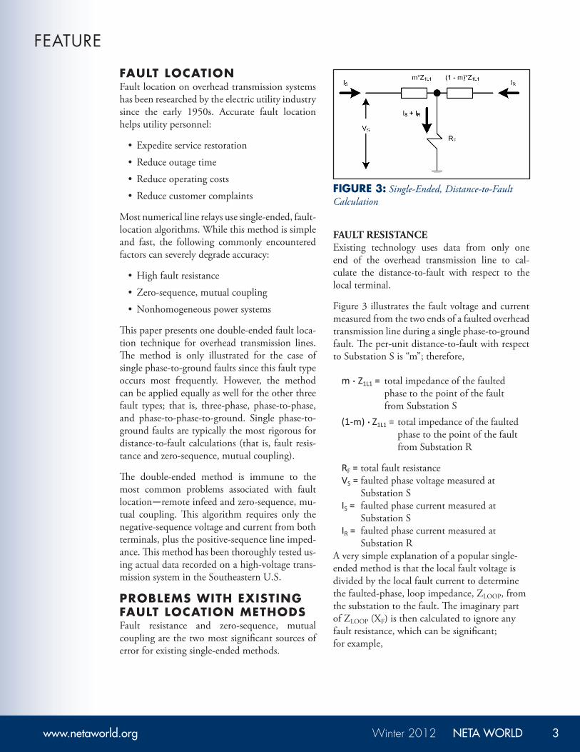
FAULT RESISTANCEExisting technology uses data from only one end of the overhead transmission line to cal-culate the distance-to-fault with respect to the local terminal.
Figure 3 illustrates the fault voltage and current measured from the two ends of a faulted overhead transmission line during a single phase-to-ground fault. The per-unit distance-to-fault with respect to Substation S is “m”; therefore,
m . Z1L1 = total impedance of the faulted phase to the point of the fault from Substation S
(1-m) . Z1L1 = total impedance of the faulted phase to the point of the fault from Substation R
RF = total fault resistance VS = faulted phase voltage measured at
Substation S IS = faulted phase current measured at
Substation S IR = faulted phase current measured at
Substation RA very simple explanation of a popular single-ended method is that the local fault voltage is divided by the local fault current to determine the faulted-phase, loop impedance, ZLOOP, from the substation to the fault. The imaginary part of ZLOOP (XF) is then calculated to ignore any fault resistance, which can be significant; for example,
END-TO-END TESTING OF DOUBLE-ENDED FAULT LOCATORSFOR HIGH-VOLTAGE, OVERHEAD TRANSMISSION LINES
NETAWORLD • 2525
FEATURE
ZLOOP = VS/IS Equation1 XF=Ιm{ZLOOP} Equation2
Where
Ιm{…}=Imaginarypartof…
The fault reactance (XF) is then divided by the total reactance of the transmission line (XL) to estimate the per-unit distance-to-fault with respect to Station S.
m = XF/XL Equation3
Equations 1 through 3 are approximations, and as such are intended only to help the reader visualize how to calculate the distance-to-fault for a single phase-to-ground fault. Use zero-sequence compensation to measure the distance-to-fault in terms of positive-sequence line impedance only.
REMOTE INFEEDIR, the fault current flowing into the fault resistance from the opposite end of the overhead transmission line, is referred to as remote infeed. Herein lies the main problem with the method outlined previously, since it was assumed that the faulted phase current from both ends of the overhead transmission line are in-phase. If there is load flow, this is typically not the case. As the angular difference between IS and IR increases, so does the error.
The error occurs because the faulted-phase voltage measured at Substation S (VS) is dependent on the faulted-phase current flowing from Sub-station R (IR).
The faulted-phase voltage measured at Substa-tion S is derived via Kirchhoff’s Voltage Law (the sum of the voltages measured around any loop equals zero).
VS = IS . m x Z1L1 . (IS + IR) . RF Equation4a
If there is an angular displacement between IS
and IR, a reactance component is introduced due to the voltage drop across the fault resistance when the imaginary part of the faulted-phase, loop impedance is calculated.
VS/IS = m . Z1L1 . IS + IR . RF Equation4b IS
VS/IS = m . Z1L1+(1+α). RF Equation4c
α=IR/IS Equation4d
If the angle of IS is equal to the angle of IR, then the imaginary part of α . RF is zero; otherwise, the value is non-zero and error is introduced. The amount of error increases with the value α.
Equations 4a through 4d are approximations and as such are only intended to help the reader visualize how to calculate the distance-to-fault for a single phase-to-ground fault.
ZERO-SEQUENCE, MUTUAL COUPLING WITH ANOTHER OVERHEAD TRANSMISSION LINEWhen two or more overhead transmission lines share the same right-of-way, there is coupling between the lines in the zero-sequence network since these components are in-phase.
Faul t res is tance and zero-sequence, mutual coupl ing are the two most
s igni f icant sources of error for exis t ing s ingle-ended methods.
www.netaworld.org Winter 2012 NETA WORLD 4
END-TO-END TESTING OF DOUBLE-ENDED FAULT LOCATORSFOR HIGH-VOLTAGE, OVERHEAD TRANSMISSION LINES
2626 • WINTER 2012
FEATURE
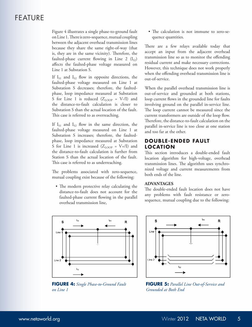
Figure 4 illustrates a single phase-to-ground fault on Line 1. There is zero-sequence, mutual coupling between the adjacent overhead transmission lines because they share the same right-of-way (that is, they are in the same vicinity). Therefore, the faulted-phase current flowing in Line 2 (IS2) affects the faulted-phase voltage measured on Line 1 at Substation S.
If IS1 and IS2 flow in opposite directions, the faulted-phase voltage measured on Line 1 at Substation S decreases; therefore, the faulted-phase, loop impedance measured at Substation S for Line 1 is reduced (ZLOOP = V-/I) and the distance-to-fault calculation is closer to Substation S than the actual location of the fault. This case is referred to as overreaching.
If IS1 and IS2 flow in the same direction, the faulted-phase voltage measured on Line 1 at Substation S increases; therefore, the faulted-phase, loop impedance measured at Substation S for Line 1 is increased (ZLOOP = V+/I) and the distance-to-fault calculation is further from Station S than the actual location of the fault. This case is referred to as underreaching.
The problems associated with zero-sequence, mutual coupling exist because of the following:
•Themodernprotectiverelaycalculatingthedistance-to-fault does not account for the faulted-phase current flowing in the parallel overhead transmission line,
•The calculation is not immune to zero-se-quence quantities.
There are a few relays available today that accept an input from the adjacent overhead transmission line so as to monitor the offending residual current and make necessary corrections. However, this technique does not work properly when the offending overhead transmission line is out-of-service.
When the parallel overhead transmission line is out-of-service and grounded at both stations, loop current flows in the grounded line for faults involving ground on the parallel in-service line. The loop current cannot be measured since the current transformers are outside of the loop flow. Therefore, the distance-to-fault calculation on the parallel in-service line is too close at one station and too far at the other.
DOUBLE-ENDED FAULT LOCATIONThis section introduces a double-ended fault location algorithm for high-voltage, overhead transmission lines. The algorithm uses synchro-nized voltage and current measurements from both ends of the line.
ADVANTAGESThe double-ended fault location does not have any problems with fault resistance or zero-sequence, mutual coupling due to the following:
FIGURE 4: Single Phase-to-Ground Fault on Line 1
FIGURE 5: Parallel Line Out-of-Service and Grounded at Both End
• Use of time-synchronized voltage andcurrent measurements from both ends of the overhead transmission line.
•Only the negative-sequence voltage andcurrent is used to calculate the fault location.
Today, time-synchronization is available and commonly applied in substation control rooms via GPS satellite clock receivers. Both modern protective relays and digital fault recorders record the fault voltage and current from each end of the overhead transmission line.
The voltage and current measurements must be filtered such that only the fundamental quantities (60 Hz components in the United States) are applied for the calculations. Modern protective relays filter the voltage and current prior to executing any protection-related functions. These signals are usually available via an event report.
DERIVATIONTransform voltage and current measured dur-ing fault conditions to their respective positive-, negative-, and zero-sequence quantities. Neg-ative-sequence quantities are present for single phase-to-ground, phase-to-phase, and phase-to-phase-to-ground faults. Therefore, negative-sequence quantities are very reliable.
The following two equations demonstrate how to calculate the negative-sequence voltage and current from the three-phase voltage and current measurements.
V2=0.333. (Vɑ+ɑ2. Vb+ɑ. Vc) Equation5ɑ
I2=0.333. (Iɑ+ɑ2. Ib+ɑ. Ic) Equation5b
Where:
ɑ =1120°
ɑ2 =1-120°
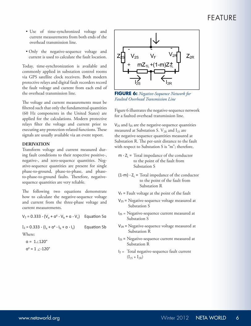
Figure 6 illustrates the negative-sequence network for a faulted overhead transmission line.
V2S and I2S are the negative-sequence quantities measured at Substation S. V2R and I2S are the negative-sequence quantities measured at Substation R. The per-unit distance to the fault with respect to Substation S is “m”; therefore,
m . ZL = Total impedance of the conductor to the point of the fault from Substation S
(1-m) . ZL = Total impedance of the conductor to the point of the fault from Substation R
VF = Fault voltage at the point of the fault
V2S = Negative-sequence voltage measured at Substation S
I2S = Negative-sequence current measured at Substation S
V2R = Negative-sequence voltage measured at Substation R
I2S = Negative-sequence current measured at Substation R
I2 = Total negative-sequence fault current (I2S + I2R)
FEATURE
FIGURE 6: Negative-Sequence Network for Faulted Overhead Transmission Line
Determine the apparent negative-sequence source impedances at Substations S and R as follows:
Z2S = - V2S/I2S Equation6a
Z2R = - V2R/I2R Equation6b
Derive two loop voltage equations in terms of the fault voltage:
at Substation S
-V2S + I2S. m . ZL + VF = 0
VF = V2S - m . I2S. ZL Equation7
at Substation R
-V2R + I2R. (1 – m) . ZL + VF= 0
VF = V2S+ m . I2R. ZL –I2R. ZL Equation8
Set the two equations above equal to each other and solve for “m” with respect to Station S.
V2S - m . I2S. ZL = V2S + m . I2S. ZL –I2R. ZL
V2S - V2S + I2S. ZL = m . I2. ZL Equation9
m(S) = V2S - V2R + I2R. Z1L
I2. ZL Equation10
HOW TO TEST THE FAULT LOCATORThis section illustrates how to use time-synchronized test signals to verify that the double-ended, fault locator works correctly. The fault locating equipment must be enabled at both terminals and the communication channel must be available.
Figure 7 is a simple model of a faulted transmission line. Substation S is the reference bus with respect to the distance-to-fault (m).
Equation (11) calculates the per unit distance-to-fault with respect to Substation S:
m = V2S - V2R + I2R. ZL
I2. ZIL Equation11
EXAMPLE 1The first example is the case of a resistive phase-to-ground fault on A-phase located 75 percent of the line (15 miles) from Substation S. It was simulated using Mathcad. You can also use short-circuit software such as ASPEN OneLiner or CAPE. Moderate load prior to the fault was modeled and the line is mutually coupled to another transmission line. The fault voltage and current at each end of the line are as follows:
VAS= 53.4-32.1°voltsVAR= 55.6-18.1°volts
VBS= 68.6-128.5°volts VBR=63.2-123.0°volts
VCS= 63.9115.2°voltsVCR=66.3114.6°volts
The negative-sequence voltage and negative-sequence current are as follows:
V2S=7.86-133.8°volts V2R=6.90-133.6°volts
I2S=0.58-13.9°amperes I2R=2.82-36.4°amperes
Equation (11) yields a result of 75 percent that matches the actual fault location. This example shows that equation (11) is immune to problems
associated with fault resistance and zero-sequence, mutual coupling since it only uses negative-sequence quantities.
EXAMPLE 2This example is an actual case where a phase-to-ground fault on A-phase occurred on a 230 kV overhead transmission line and was captured by digital fault recorders at both ends. Conventional methods proved futile when utility personnel tried to locate the fault. The fault turned out to be an old oak tree growing under the line. This vegetation represented an extremely high level of fault resistance (that is, many times greater than the impedance of the transmission line). The double-ended, distance-to-fault equation correctly calculated the distance-to-fault with an error of less than 5 percent. The following are the actual calculations for this case.
Here are the time synchronized negative-sequence quantities measured at each end of the line:
The actual line length is 35.43 miles. Therefore, the distance-to-fault with respect to Substation S was 12.5 miles. The actual distance-to-fault was 13 miles.
EXAMPLE 3A B-C phase-to-phase fault occurred on a 230 kV overhead transmission line. The fault was due to a truck that caught fire under the line. The resulting smoke created a path for electrical current to flow between B- and C-phase conductors. The double-ended distance-to-fault equation was applied using the negative-sequence voltage and current recorded by instrumentation at the two ends of
the line. The error was less than two percent. Below are the actual calculations for this case.
V2S=51.71.9°kV V2R=37.91.3°kV
I2S=11,90096.5°A I2R=2,47094°A
I2 = I2S + I2R=14,37096°A
Z1L=11.9685.8°Ωprimary
|m|=0.092per-unit
The actual line length is 21 miles; therefore, the distance-to-fault with respect to Substation S was 1.93 miles.
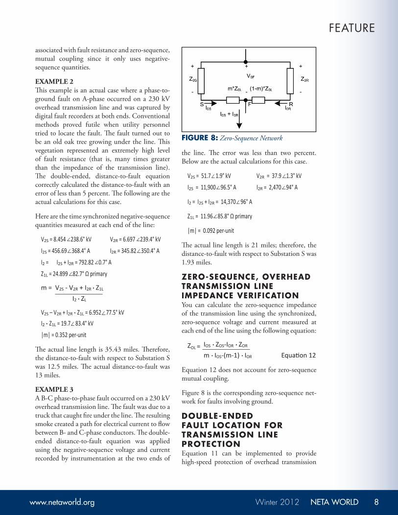
ZERO-SEQUENCE, OVERHEAD TRANSMISSION LINE IMPEDANCE VERIFICATIONYou can calculate the zero-sequence impedance of the transmission line using the synchronized, zero-sequence voltage and current measured at each end of the line using the following equation:
ZOL = IOS . ZOS-IOR . ZOR
m . IOS-(m-1) . IOR Equation12
Equation 12 does not account for zero-sequence mutual coupling.
Figure 8 is the corresponding zero-sequence net-work for faults involving ground.
DOUBLE-ENDED FAULT LOCATION FOR TRANSMISSION LINE PROTECTIONEquation 11 can be implemented to provide high-speed protection of overhead transmission
lines. Terminal voltage and current phasors can be calculated in real time and then passed from end-to-end via a digital communications channel. The double-ended fault locator is immune to many problems associated with conventional distance based-schemes such as overreach and underreach.
CONCLUSIONSThis paper explains how to test double-ended fault locators for high-voltage, overhead transmission lines. There are many similarities to testing high-speed communication-assisted tripping schemes (HSCATS); however, there are some important differences which are covered here in detail. Note that double-ended fault location is coming into vogue, and these tests can be performed in unison while testing the HSCATS.
When a disturbance (for example, a lightning strike) occurs on a high-voltage, overhead transmission line, the line must be checked for any possible damage. If the distance-to-fault is known, line crews can be quickly dispatched for any necessary repair. Otherwise, a lot of time and expense is required to patrol the overhead line for possible damage.
Modern protective relays calculate the distance-to-fault using data (voltage and current) measured at the respective locations. This is referred to as a single-ended method. Error typically occurs when there is fault resistance (for example, wind blows a tree into the line conductor) and power is flowing through the line.
The double-ended method uses time-synchronized, filtered data from both ends of the overhead transmission line to determine the exact distance to the disturbance with respect to either
end. The double-ended fault location does not have any problems with fault resistance or zero-sequence, mutual coupling due to the following:
• Time-synchronized voltage and currentmeasurements are used from both ends of the overhead transmission line.
• Only the negative-sequence voltage andcurrent is used to calculate the fault location.
• Today, time-synchronization is commonlyavailable and applied in substation control rooms via GPS satellite clock receivers. Both modern protective relays and digital fault recorders typically record the fault voltage and current from each end of the overhead transmission line. Use this data to accurately calculate the distance to the fault.
Steve Turner is a Senior Ap-plications Engineer at Beckwith Electric Company. His previous experience includes working as an application engineer with GEC Alstom, an application engineer in the international market for SEL, focusing on transmission line protection applications. Steve worked for Progress Energy, where he developed a patent for
double-ended fault location on transmission lines.
Steve has both a BSEE and MSEE from Virginia Tech Univer-sity. He has presented at numerous conferences including: Geor-gia Tech Protective Relay Conference, Western Protective Relay Conference, ECNE and Doble User Groups, as well as various international conferences. Steve is a senior member of IEEE.
FEATURE
Note that double-ended faul t locat ion is coming in to vogue, and these tes ts
can be per formed in unison whi le tes t ing the HSCATS.