FEATURE Sealing Technology July 2013 8 Leakage at radial lip seals is not only annoy- ing, but also expensive. Usually, leakage is considered to be the result of failure of the seal element, but very often it is caused by specific characteristics of the shaft counterface. Lead on a ground shaft counterface disturbs the sealing mechanisms and causes early failure of the entire sealing system. Too little grinding allowance, improper grinding parameters or mishandling of the work piece, to name but a few factors, can cause lead on shaft counter- faces. Detecting these defects is not a trivial problem because such lead-afflicted surfaces often meet all other quality requirements. Sealing system A reliable radial lip seal consists not only of the ‘‘seal element’’. [1] It is a complex tribologi- cal system that consists of the seal ring, shaft counterface, the fluid to be sealed, and the sur- rounding and operation conditions (Figure 1). These components are in constant interaction. Changes in one component can very easily dis- turb the balance of the system. The decisive sealing mechanism results from an active pumping effect of the seal ring. The elastomeric sealing edge is shaped geometrically in such way that when it is in contact with the shaft counterface an asymmetric pressure distri- bution is formed. In operation, surface structures on the elastomeric sealing edge are distorted in the circumferential direction, which causes a trans- port of fluid from the air side to the oil side of the seal. Within a functioning system there is a balance between fluid which is entering the sealing contact from the oil side and fluid that is pumped back. Another positive effect of this sealing mecha- nism is the continuous exchange of fluid under the sealing edge. Thus, heat is dissipated and the sealing edge is always well lubricated. This diminishes friction, ageing and wear. Shaft counterface In order not to disturb the described effect, the shaft must be free of lead and must not show any superimposed pumping effect of the coun- terface itself. If there are lead structures on the shaft counterface, these can – in a fashion that is similar to the way in which a conveyor screw works – transport fluid through the sealing contact (Figure 2). If the pumping effect of the shaft counterface is higher than the pumping effect of the seal ring, the result is dependent on the direction of rotation, leakage or dry run. Visible leakage leads to the immediate failure of the system. Dry run causes reinforcing fric- tion, wear and a temperature increase in the sealing contact. The seal ring is then damaged thermally and leakage occurs. According to the radial lip seals standards DIN 3760/3761, [2, 3] shaft counterfaces are to be manufactured free of lead and in a roughness spectrum R z of 1–5 µm, with a R max of 6 µm. In addition, they must be free from any defects and damage. In practice, plunge grinding with a long spark-out time has proven itself as the standard manufacturing method. The surface qual- ity given by the roughness values in the DIN standard is easy to achieve and to verify. The most important requirement for the shaft counterface is its lead-free condition, however, this cannot be verified using common, two- dimensional (2D) roughness values. Therefore, it would be obvious to use pol- ished and extremely smooth shaft counterfaces. These are understandably free of lead, but have no basic roughness. However, this is especially a big problem since it is the basic roughness that reduces friction because of the reduced contact area between the elastomeric sealing edge and the shaft counterface. Moreover, the basic roughness is responsible for what is often referred to as “conditioning” of the sealing edge. This process involves initial roughening of the elastomeric sealing edge, which is absolutely necessary for the active pumping effect, needed for the seal ring to function properly. So, it is obvious that the lim- its given in the standards should be met and the lead-free state must be ensured. Proper plunge grinding of hardened shaft counterfaces is a time-consuming and expensive manufacturing process. Manufacturing engi- neers often want to optimise such processes. Longer dressing cycles of the grinding wheel, shorter spark-out times or smaller allowances decrease the production costs, but also hold a great risk. In extreme cases, the slightest param- eter changes can mean the difference between the production of a good or bad part. It also may result in a large number of manufactured products being rejected. How to measure lead in sealing technology? Figure 1. A schematic of a radial lip seal system. Dipl.-Ing. Matthias Baumann, Dr.-Ing. Frank Bauer and Prof. Dr.-Ing. Habil. Werner Haas – Institut für Maschinenelemente, University of Stuttgart, Stuttgart, Germany; and Dr.-Ing. Pat.-Ing. Gert Baitinger, Central Research and Development, MAHLE International GmbH (formerly at the Institut für Maschinenelemente) Radial lip seal leakage is often caused by lead, for example, oriented surface structures deviating from the circumferential direction, on the ground shaft counterface. The shaft must be free of lead and not show any superimposed pumping effect of the counterface itself in order to ensure that good sealing action is achieved. This article describes various ways of measuring lead and shows that a holistic measurement and evaluation approach is required.
Transcript
fEATurE
Sealing Technology July 20138
Leakageatradiallipsealsisnotonlyannoy-ing, but also expensive. Usually, leakage is considered to be the result of failure of the seal element, but very often it is caused by specific characteristics of the shaft counterface.Leadonagroundshaftcounterfacedisturbs
the sealing mechanisms and causes early failure of the entire sealing system. Too little grinding allowance, improper grinding parameters or mishandling of the work piece, to name but a few factors, can cause lead on shaft counter-faces. Detecting these defects is not a trivial problem because such lead-afflicted surfaces often meet all other quality requirements.
Sealing systemA reliable radial lip seal consists not only of the ‘‘seal element’’.[1] It is a complex tribologi-cal system that consists of the seal ring, shaft counterface, the fluid to be sealed, and the sur-rounding and operation conditions (Figure 1). These components are in constant interaction. Changes in one component can very easily dis-turb the balance of the system.
The decisive sealing mechanism results from an active pumping effect of the seal ring. The elastomeric sealing edge is shaped geometrically in such way that when it is in contact with the shaft counterface an asymmetric pressure distri-bution is formed.
In operation, surface structures on the elastomeric sealing edge are distorted in the circumferential direction, which causes a trans-port of fluid from the air side to the oil side of the seal. Within a functioning system there is a balance between fluid which is entering the sealing contact from the oil side and fluid that is pumped back.
Another positive effect of this sealing mecha-nism is the continuous exchange of fluid under the sealing edge. Thus, heat is dissipated and the sealing edge is always well lubricated. This diminishes friction, ageing and wear.
Shaft counterfaceIn order not to disturb the described effect, the shaft must be free of lead and must not show any superimposed pumping effect of the coun-terface itself. If there are lead structures on the shaft counterface, these can – in a fashion that is similar to the way in which a conveyor screw works – transport fluid through the sealing contact (Figure 2).
If the pumping effect of the shaft counterface is higher than the pumping effect of the seal ring, the result is dependent on the direction of rotation, leakage or dry run.
Visible leakage leads to the immediate failure of the system. Dry run causes reinforcing fric-tion, wear and a temperature increase in the
sealing contact. The seal ring is then damaged thermally and leakage occurs.
According to the radial lip seals standards DIN 3760/3761,[2, 3] shaft counterfaces are to be manufactured free of lead and in a roughness spectrum Rz of 1–5 µm, with a Rmax of 6 µm. In addition, they must be free from any defects and damage.
In practice, plunge grinding with a long spark-out time has proven itself as the standard manufacturing method. The surface qual-ity given by the roughness values in the DIN standard is easy to achieve and to verify. The most important requirement for the shaft counterface is its lead-free condition, however, this cannot be verified using common, two-dimensional (2D) roughness values.
Therefore, it would be obvious to use pol-ished and extremely smooth shaft counterfaces. These are understandably free of lead, but have nobasicroughness.However,thisisespeciallyabig problem since it is the basic roughness that reduces friction because of the reduced contact area between the elastomeric sealing edge and the shaft counterface.
Moreover, the basic roughness is responsible for what is often referred to as “conditioning” of the sealing edge. This process involves initial roughening of the elastomeric sealing edge, which is absolutely necessary for the active pumping effect, needed for the seal ring to function properly. So, it is obvious that the lim-its given in the standards should be met and the lead-free state must be ensured.
Proper plunge grinding of hardened shaft counterfaces is a time-consuming and expensive manufacturing process. Manufacturing engi-neers often want to optimise such processes. Longerdressingcyclesofthegrindingwheel,shorter spark-out times or smaller allowances decrease the production costs, but also hold a great risk. In extreme cases, the slightest param-eter changes can mean the difference between the production of a good or bad part. It also may result in a large number of manufactured products being rejected.
How to measure lead in sealing technology?
Figure 1. A schematic of a radial lip seal system.
Dipl.-Ing. Matthias Baumann, Dr.-Ing. Frank Bauer and Prof. Dr.-Ing. Habil. Werner Haas – Institut für Maschinenelemente, University of Stuttgart, Stuttgart, Germany; and Dr.-Ing. Pat.-Ing. Gert Baitinger, Central Research and Development, MAHLE International GmbH (formerly at the Institut für Maschinenelemente)
Radial lip seal leakage is often caused by lead, for example, oriented surface structures deviating from the circumferential direction, on the ground shaft counterface. The shaft must be free of lead and not show any superimposed pumping effect of the counterface itself in order to ensure that good sealing action is achieved. This article describes various ways of measuring lead and shows that a holistic measurement and evaluation approach is required.
fEATurE
July 2013 Sealing Technology9
What is lead?In mechanical engineering the term lead has different definitions. In sealing technology, eli-gible structures on the shaft counterface which entail an axially directed fluid pumping are called lead.
These are not necessarily only periodic and thread-like structures running around the circumference (macro-lead), which is com-monly assumed, but small, directed structures (micro-lead), or isolated scratches on the sur-face of the shaft can also cause fluid pumping and, therefore, are also defined as lead. Even structures oriented directly in a circumfer-ential direction, but relatively deep, can – in combination with a built-in seal ring that is askew – result in a pumping effect. According to MBN 31007-7,[4] this is called zero lead.Leadoriginatesinavarietyofways.The
dressing process is, for example, a possible source of error when grinding. In this case, structures on the grinding wheel, originat-ing from the dressing process, are mapped to the workpiece. This can be caused by the selection of unfavourable speed ratios between the workpiece and the grinding wheel.
Offset lead can also occur. Misalignment of the workpiece and grinding-wheel axes causes fine lead structures. Even too little grinding allowance is not without risks. A low in-feed while grinding may result in a structure created during the previous manufacturing process (for example, turning structures) remaining on the shaft surface. A similar effect is caused by an insufficient spark-out time. Whilst a period of 30 seconds[5] is usu-ally recommended, this is often shortened to just a few seconds. Without comprehensive quality inspection, faulty components have far-reaching consequences.
Another annoying source of error may creep into production after the machining process has been completed, and occurs while components are being handled. The best surface treatment is useless if components are not transported carefully.
Lead measurementThe lead-free state of a shaft counterface cannot be checked by measuring 2D surface rough-ness. This can only show that the grinding process has been run with wrong manufactur-ing parameters. Special lead measuring systems have to be used. Nevertheless, the analysis of lead is still challenging.
In the sections that follow, various methods of analysis are described which are actually available or are in development for future use.
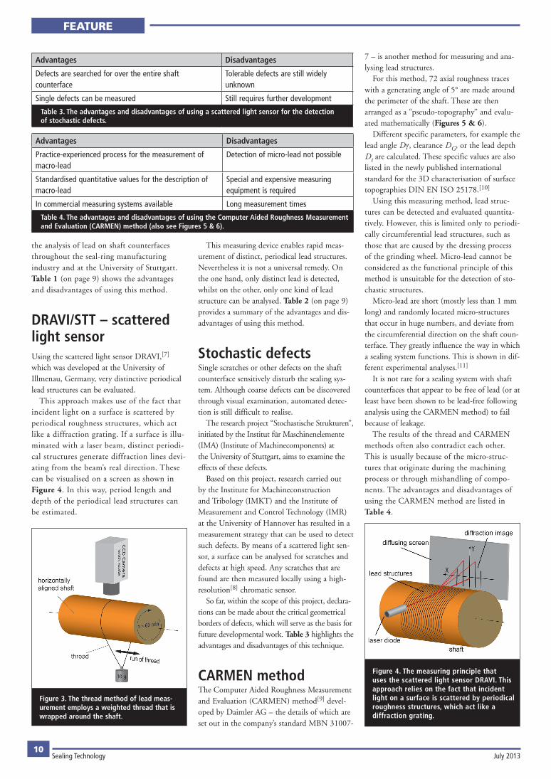
Thread methodThe so-called ‘‘thread method’’ is an old approach to analysing lead.[6] In this method the shaft is mounted horizontally in a chuck. A weighted thread is wrapped around the shaft as shown in Figure 3 (on page 10). If there is lead on the shaft counterface, the thread moves in an axial direction when the shaft rotates.
The way in which lead acts depends on the direction of rotation, so the direction in which the thread moves is reversed when the rota-tional direction is changed. As a result, oriented scratches, micro-lead and macro-lead can be qualitatively identified.
The exact parameters used for this method vary from company to company. A dry or lubri-
cated surface may be demanded, and one com-pany may use nylon threads (like fishing lines) whilst others rely on special cotton thread. Also, the demanded test speeds are different.
These aspects, taken together, point to a crucial weakness of this method. Measurement results can vary widely from user to user and for different surface wetting and revolution speeds. In addition, there is no universally valid standard for this method. Statements about the strength of the lead (for example, the speed of the thread run) are rather limited and not easily compared.
This method may seem primitive when, these days, high-resolution three-dimensional (3D)surfacemetrologyisavailable.However,it has often enough proved itself in practice and, therefore, is an established method for
Figure 2. The way in which lead influences the pumping effect of the shaft.
Advantages Disadvantages
Easy to realise at reasonable costs Not standardised – many different measuring regulations available
Good experiences with macro-lead and micro-lead
No quantitative statements possible
Influence of the operator on the measurement result is not excluded
Table 1. Advantages and disadvantages of using the thread method (also see Figure 3).
Advantages Disadvantages
Manageable and cost-efficient device Experienced operator is necessary
Quick and direct use after the machining process is possible Detects only one kind of lead (for example, dressing lead)
Only detects distinctive lead structure
Table 2. A summary of the advantages and disadvantages of using the scattered light sensor DRAVI developed at the University of Illmenau.
fEATurE
Sealing Technology July 201310
the analysis of lead on shaft counterfaces throughout the seal-ring manufacturing industry and at the University of Stuttgart. Table 1 (on page 9) shows the advantages and disadvantages of using this method.
DRAVI/STT – scattered light sensorUsing the scattered light sensor DRAVI,[7] which was developed at the University of Illmenau, Germany, very distinctive periodical lead structures can be evaluated.
This approach makes use of the fact that incident light on a surface is scattered by periodical roughness structures, which act like a diffraction grating. If a surface is illu-minated with a laser beam, distinct periodi-cal structures generate diffraction lines devi-ating from the beam’s real direction. These can be visualised on a screen as shown in Figure 4. In this way, period length and depth of the periodical lead structures can be estimated.
This measuring device enables rapid meas-urement of distinct, periodical lead structures. Nevertheless it is not a universal remedy. On the one hand, only distinct lead is detected, whilst on the other, only one kind of lead structure can be analysed. Table 2 (on page 9) provides a summary of the advantages and dis-advantages of using this method.
Stochastic defectsSingle scratches or other defects on the shaft counterface sensitively disturb the sealing sys-tem. Although coarse defects can be discovered through visual examination, automated detec-tion is still difficult to realise.
The research project ‘‘Stochastische Strukturen’’, initiated by the Institut für Maschinenelemente (IMA) (Institute of Machinecomponents) at the University of Stuttgart, aims to examine the effects of these defects.
Based on this project, research carried out by the Institute for Machineconstruction and Tribology (IMKT) and the Institute of Measurement and Control Technology (IMR) attheUniversityofHannoverhasresultedinameasurement strategy that can be used to detect such defects. By means of a scattered light sen-sor, a surface can be analysed for scratches and defects at high speed. Any scratches that are found are then measured locally using a high-resolution[8] chromatic sensor.
So far, within the scope of this project, declara-tions can be made about the critical geometrical borders of defects, which will serve as the basis for future developmental work. Table 3 highlights the advantages and disadvantages of this technique.
CARMEN methodThe Computer Aided Roughness Measurement and Evaluation (CARMEN) method[9] devel-oped by Daimler AG – the details of which are set out in the company’s standard MBN 31007-
7 – is another method for measuring and ana-lysing lead structures.
For this method, 72 axial roughness traces with a generating angle of 5° are made around the perimeter of the shaft. These are then arranged as a ‘‘pseudo-topography’’ and evalu-ated mathematically (Figures 5 & 6).
Different specific parameters, for example the lead angle Dγ, clearance DG, or the lead depth Dt are calculated. These specific values are also listed in the newly published international standard for the 3D characterisation of surface topographies DIN EN ISO 25178.[10]
Using this measuring method, lead struc-tures can be detected and evaluated quantita-tively.However,thisislimitedonlytoperiodi-cally circumferential lead structures, such as those that are caused by the dressing process of the grinding wheel. Micro-lead cannot be considered as the functional principle of this method is unsuitable for the detection of sto-chastic structures.
Micro-lead are short (mostly less than 1 mm long) and randomly located micro-structures that occur in huge numbers, and deviate from the circumferential direction on the shaft coun-terface. They greatly influence the way in which a sealing system functions. This is shown in dif-ferent experimental analyses.[11]
It is not rare for a sealing system with shaft counterfaces that appear to be free of lead (or at least have been shown to be lead-free following analysis using the CARMEN method) to fail because of leakage.
The results of the thread and CARMEN methods often also contradict each other. This is usually because of the micro-struc-tures that originate during the machining process or through mishandling of compo-nents. The advantages and disadvantages of using the CARMEN method are listed in Table 4.
Figure 4. The measuring principle that uses the scattered light sensor DRAVI. This approach relies on the fact that incident light on a surface is scattered by periodical roughness structures, which act like a diffraction grating.
Figure 3. The thread method of lead meas-urement employs a weighted thread that is wrapped around the shaft.
Advantages Disadvantages
Defects are searched for over the entire shaft counterface
Tolerable defects are still widely unknown
Single defects can be measured Still requires further development
Table 3. The advantages and disadvantages of using a scattered light sensor for the detection of stochastic defects.
Advantages Disadvantages
Practice-experienced process for the measurement of macro-lead
Detection of micro-lead not possible
Standardised quantitative values for the description of macro-lead
Special and expensive measuring equipment is required
In commercial measuring systems available Long measurement times
Table 4. The advantages and disadvantages of using the Computer Aided Roughness Measurement and Evaluation (CARMEN) method (also see Figures 5 & 6).
fEATurE
July 2013 Sealing Technology11
Micro-structure analysisCircumferential lead structures can be detected using the CARMEN method, but this tech-nique is unsuitable for detecting many fine, short and directed micro-structures. The thread method can detect micro-lead, but not quanti-tatively.
A research project[12] was carried out at the IMA to deal with the lack of quantitative cap-ture and assessment techniques applicable to micro-lead. Following the success of this project funding was made available for further research that deals with micro-structures and waviness. The initial results of this work were given in a presentationatthe68thSTLEAnnualMeeting2013, which was held earlier this year on 5–9 May in Detroit, Michigan, USA.
Based on optical surface metrology, digital image-processing algorithms are used to evalu-ate micro-structures. This approach is illustrat-ed schematically in Figure 7 (on page 12).
The starting point for this evaluation is a segmented binary image of the directed micro-structures which is obtained from measurement data using common filter-ing techniques. An ellipse is ‘‘fitted’’ to, or ‘‘encloses’’, each of the isolated micro-struc-tures. From the longer half-axis of the ellipse, the angle adjustment relative to the circum-ferential direction and the length of the micro-structure is determined. The length of the shorter half-axis represents the width of the structure (Figure 8, on page 12)
With the knowledge of the position of each micro-structure, the height data, for example, volume and depth, are determined. This col-lection of data is then evaluated statistically to calculate the characteristic values.
The angular orientation is determined with respect to the circumferential direction. The position of the circumferential direction, or the shaft axis in relation to the topography, must be precisely known, which means the test sample has to be exactly aligned for the measurement.
Summing up the volume of the structures with the same orientation, and plotting them against the angle of orientation gives the distri-bution curve for the cumulated micro-structure volume – virtually a ‘‘fingerprint’’ of the sur-face.
If the pumping volume is dominant in a direction deviating from the circumferential direction, or if the distribution curve is asym-metric, the existence of micro-lead can be assumed. Good-quality surfaces exhibit a high symmetry and a low spread. Table 5 presents the advantages and disadvantages of applying micro-structure analysis.
How is lead measured properly?Leadcanbeonlyevaluatedusingspecialisedmeasuring techniques.
Measuring systems that are currently used are not entirely satisfactory. Circumferential macro-lead analysis appears to be the focus of attention, whilst the more critical micro-lead and stochastic defects are often ignored, which leads to serious misjudgement.Leadisaproblemthatencompassesmultiple-
length scales. Therefore, in order to cover all
forms of lead a holistic measurement and evalu-ation approach is required.
Different measurement and evaluation methods have to be used. A combination of the CARMEN method and micro-structure analysis under devel-opment at the University of Stuttgart, provides a purposeful way of considering every relevant lead characteristic. Although this is complex and expensive, it must be accepted for comprehensive quality assurance of shaft counterfaces.
Another issue that is becoming more and more urgent is the ability to measure lead on large and heavy parts. These cannot be simply
Figure 6. Measurement results of a plunge ground shaft counterface.
Figure 5. A schematic procedure for the Computer Aided Roughness Measurement and Evaluation (CARMEN) method.
Advantages Disadvantages
Quantitative detection of micro-lead Exact alignment of the shaft axis is necessary
Measured data also can be used for the calculation of the three-dimensional roughness parameters, in accord-ance with DIN EN ISO 25178
Not yet available as commercial software
Capture of macro-lead not possible
Table 5. Specific advantages and disadvantages of applying micro-structure analysis.
fEATurE/PATENTS
12Sealing Technology July 2013
mounted on measuring instruments that are currently used. Researchers at the University of Stuttgart are pursuing ways of solving such challenging measurement problems.
References1. Bauer,F.andHaas,W.,Radiallip
seals – overview and function, 18th International Colloquium Tribology, Ostfildern-Nellingen, Germany, 10–12 January 2012, p. 155, ‘Book of Synopses 2012’, W.J. Bartz (Hrsg.)–TAE,Esslingen,Germany(ISBN 3-924813-97-3).
2. ‘DIN 3160: Radial-Wellendichtringe’, Deutsches Institut für Normung eV, September 1996.
3. ‘DIN 3161: Radial-Wellendichtringe für Kraftfahrzeuge’, Deutsches Institut für Normung eV, January 1984
4. ‘MBN 31 007-7: Geometrical Product Specifications (GPS) – Surface Texture – Measurement and Evaluation Method for theAssessmentofLeadReducedDynamic
Sealing Surfaces, (factory standard), Daimler Ag, September 2008.
10. ‘ISO 25178: Geometrical product specifications (GPS) – Surface texture: Areal’, International Organization for Standardization, September 2012.
11. Kunstfeld, T., ‘Einfluss der Wellenoberfläche auf das Dichtverhalten von Radial-Wellendichtungen’ (dissertation 2005), Universität Stuttgart, Institutsbericht Nr. 115.
12. Baitinger, G., Multiskalenansatz mit Mikrostrukturanalyse zur Drallbeurteilung von Dichtungsgegenlaufflächen (dissertation 2011), Universität Stuttgart, Institutsbericht Nr. 135
Figure 7. A process schematic of micro-structure analysis.
Figure 8. Characterisation of single micro-structures, showing the ellipse ‘‘fitted’’ to, or ‘‘enclosing’’, an isolated micro-structure.
PATENTSSealing arrangement for a syringeApplicant: Abbott Laboratories, USAA sealing arrangement for a syringe contain-ing a high water-content product and for use in a drug infusion system forms the subject of this patent. The syringe includes a plunger that carries front and rear O-rings made of a compound such as chlorobutyl or bromobutyl rubber, which imparts low gas permeability characteristics to the seals. The plunger may
be moulded as a single part or as two com-ponents. The O-rings may be surface treated with a lubricant to improve sealing where the moulding process gives rise to parting lines in the seal glands, which can result in leak paths on the inner diameter of the O-rings. The latter provide a gas-tight sliding seal that can withstand a change in temperature of –25°C to 40°C, and the resulting thermal expansion and contraction of the high water-content product.Patent number: WO/2013/033453Inventors: M.J. Gibler, M.A. Bennett, K.R.Waeber,K.E.Hogue,C.L.Gillum, P.A.Harrell,D.A.Parrott,S.E.Mackey, R. Conjeevaram, T. Rebne, B. Clark,
J.L.HemingwayandJ.ZhouPublication date: 7 March 2013
Profiled seal
Applicant: Federal-Mogul Sealing Systems GmbH, GermanyThis invention relates to a seal (1) for sealing, against each other, an upper (2) and a lower (3) half of a housing for liquids. It is composed of a circumferential inner seal portion (4) and a circumferential outer seal portion (5) which sit against the upper and the lower housing halves, when the seal is installed. The outer seal portion has at least one ridge (6) which faces a housing half and receives a housing half rib (7)