Page 1
DATASHEET HC SERIES ULTRACAPACITORS
FEATURES AND BENEFITS Highest power performance available Lowest RC time constant Over 500,000 duty cycles Proprietary material science and packaging technology
TYPICAL APPLICATIONS Automotive subsystems Grid Stabilization Hybrid drive trains Rail system power Transportation Utility vehicles
Page 2
Page 2 Document number: 1013793.5 maxwell.com
DATASHEET HC SERIES ULTRACAPACITORS
PRODUCT SPECIFICATIONS
ELECTRICAL BCAP0001 BCAP0003 BCAP0005 BCAP0010 BCAP0025
Rated Capacitance1 1 F 3.3 F 5 F 10 F 25 F
Minimum Capacitance, initial1 0.8 F 2.6 F 4.0 F 8.0 F 25 F
Maximum ESR DC, initial1 700 mΩ 290 mΩ 170 mΩ 75 mΩ 42 mΩ
Rated Voltage (65o/85oC) 2.70 / 2.30 V 2.70 / 2.30 V 2.70 / 2.30 V 2.70 / 2.30 V 2.70 / 2.30 V
Absolute Maximum Voltage11 2.85 V 2.85 V 2.85 V 2.85 V 2.85 V
Maximum Continuous Current (ΔT = 15oC)2 0.4 ARMS 0.8 ARMS 1.1 ARMS 2.2 ARMS 2.8 ARMS
Maximum Continuous Current (ΔT = 40oC)2 0.7 ARMS 1.3 ARMS 1.8 ARMS 3.5 ARMS 4.5 ARMS
Maximum Peak Current (65o/85oC), 1 second (non repetitive) 3 0.8 / 0.7 A 2.3 / 1.9 A 3.6 / 3.1 A 8 / 7 A 16 / 14 A
Leakage Current, maximum4 0.006 mA 0.012 mA 0.015 mA 0.030 mA 0.045 mA
TEMPERATUREOperating temperature range (Cell case temperature)
Minimum -40oC -40oC -40oC -40oC -40oC
Maximum 65o / 85oC 65o / 85oC 65o / 85oC 65o / 85oC 65o / 85oC
Storage temperature range (Stored uncharged)
Minimum -40oC -40oC -40oC -40oC -40oC
Maximum 70oC 70oC 70oC 70oC 70oC
PHYSICALMass, typical 1.1 g 1.7 g 2.3 g 3.5 g 7.5 g
Terminals Wire Leads Wire Leads Wire Leads Wire Leads Wire Leads
Vibration - - - - -
Shock - - - - -
ELECTRICAL BCAP0050 BCAP0100 T01 BCAP0100 T07 BCAP0150
Rated Capacitance1 50 F 100 F 100 F 150 F
Minimum Capacitance, initial1 50 F 100 F 100 F 150 F
Maximum ESR DC, initial1 20 mΩ 15 mΩ 15 mΩ 14 mΩ
Rated Voltage (65o/85oC) 2.70 / 2.30 V 2.70 / 2.30 V 2.70 / 2.30 V 2.70 / 2.30 V
Absolute Maximum Voltage11 2.85 V 2.85 V 2.85 V 2.85 V
Maximum Continuous Current (ΔT = 15oC)2 5.4 ARMS 6.7 ARMS 6.7 ARMS 7.7 ARMS
Maximum Continuous Current (ΔT = 40oC)2 8.8 ARMS 11 ARMS 11 ARMS 13 ARMS
Maximum Peak Current (65o/85oC), 1 second (non repetitive)3 34 / 29 A 54 / 46 A 54 / 46 A 65 / 56 A
Leakage Current, maximum 4 0.075 mA 0.260 mA 0.260 mA 0.500 mA
TEMPERATUREOperating temperature range (Cell case temperature)
Minimum -40oC -40oC -40oC -40oC
Maximum 65o / 85oC 65o / 85oC 65o / 85oC 65o / 85oC
Storage temperature range (Stored uncharged)
Minimum -40oC -40oC -40oC -40oC
Maximum 70oC 70oC 70oC 70oC
PHYSICALMass, typical 13 g 23 g 22 g 32 g
Terminals Wire Leads Wire Leads Snap In Snap in
Vibration - - - -
Shock - - - -
Page 3
ELECTRICAL BCAP0001 BCAP0003 BCAP0005 BCAP0010 BCAP0025
Rated Capacitance1 1 F 3.3 F 5 F 10 F 25 F
Minimum Capacitance, initial1 0.8 F 2.6 F 4.0 F 8.0 F 25 F
Maximum ESR DC, initial1 700 mΩ 290 mΩ 170 mΩ 75 mΩ 42 mΩ
Rated Voltage (65o/85oC) 2.70 / 2.30 V 2.70 / 2.30 V 2.70 / 2.30 V 2.70 / 2.30 V 2.70 / 2.30 V
Absolute Maximum Voltage11 2.85 V 2.85 V 2.85 V 2.85 V 2.85 V
Maximum Continuous Current (ΔT = 15oC)2 0.4 ARMS 0.8 ARMS 1.1 ARMS 2.2 ARMS 2.8 ARMS
Maximum Continuous Current (ΔT = 40oC)2 0.7 ARMS 1.3 ARMS 1.8 ARMS 3.5 ARMS 4.5 ARMS
Maximum Peak Current (65o/85oC), 1 second (non repetitive) 3 0.8 / 0.7 A 2.3 / 1.9 A 3.6 / 3.1 A 8 / 7 A 16 / 14 A
Leakage Current, maximum4 0.006 mA 0.012 mA 0.015 mA 0.030 mA 0.045 mA
TEMPERATUREOperating temperature range (Cell case temperature)
Minimum -40oC -40oC -40oC -40oC -40oC
Maximum 65o / 85oC 65o / 85oC 65o / 85oC 65o / 85oC 65o / 85oC
Storage temperature range (Stored uncharged)
Minimum -40oC -40oC -40oC -40oC -40oC
Maximum 70oC 70oC 70oC 70oC 70oC
PHYSICALMass, typical 1.1 g 1.7 g 2.3 g 3.5 g 7.5 g
Terminals Wire Leads Wire Leads Wire Leads Wire Leads Wire Leads
Vibration - - - - -
Shock - - - - -
ELECTRICAL BCAP0050 BCAP0100 T01 BCAP0100 T07 BCAP0150
Rated Capacitance1 50 F 100 F 100 F 150 F
Minimum Capacitance, initial1 50 F 100 F 100 F 150 F
Maximum ESR DC, initial1 20 mΩ 15 mΩ 15 mΩ 14 mΩ
Rated Voltage (65o/85oC) 2.70 / 2.30 V 2.70 / 2.30 V 2.70 / 2.30 V 2.70 / 2.30 V
Absolute Maximum Voltage11 2.85 V 2.85 V 2.85 V 2.85 V
Maximum Continuous Current (ΔT = 15oC)2 5.4 ARMS 6.7 ARMS 6.7 ARMS 7.7 ARMS
Maximum Continuous Current (ΔT = 40oC)2 8.8 ARMS 11 ARMS 11 ARMS 13 ARMS
Maximum Peak Current (65o/85oC), 1 second (non repetitive)3 34 / 29 A 54 / 46 A 54 / 46 A 65 / 56 A
Leakage Current, maximum 4 0.075 mA 0.260 mA 0.260 mA 0.500 mA
TEMPERATUREOperating temperature range (Cell case temperature)
Minimum -40oC -40oC -40oC -40oC
Maximum 65o / 85oC 65o / 85oC 65o / 85oC 65o / 85oC
Storage temperature range (Stored uncharged)
Minimum -40oC -40oC -40oC -40oC
Maximum 70oC 70oC 70oC 70oC
PHYSICALMass, typical 13 g 23 g 22 g 32 g
Terminals Wire Leads Wire Leads Snap In Snap in
Vibration - - - -
Shock - - - -
Page 4
Page 4 Document number: 1013793.5 maxwell.com
DATASHEET HC SERIES ULTRACAPACITORS
PRODUCT SPECIFICATIONS (Cont’d)
POWER & ENERGY BCAP0001 BCAP0003 BCAP0005 BCAP0010 BCAP0025
Usable Specific Power, Pd (65o/85oC)5 1,100 / 820 W/kg
1,800 / 1,300
W/kg2,200 / 1,600
W/kg3,300 / 2,400
W/kg2,800 / 2,000
W/kg
Impedance Match Specific Power, Pmax (65o/85oC)6
2,400 / 1,700
W/kg3,700 / 2,700
W/kg4,700 / 3,400
W/kg6,900 / 5,000
W/kg5,800 / 4,200
W/kg
Specific Energy, Emax (65o/85oC)7
0.9 / 0.7
Wh/kg2.0 / 1.4
Wh/kg2.2 / 1.6
Wh/kg2.9 / 2.1
Wh/kg3.4 / 2.4
Wh/kg
Stored Energy (65o/85oC)8 0.001 / 0.001
Wh0.003 / 0.002
Wh0.005 / 0.004
Wh0.010 / 0.007
Wh0.025 / 0.018
Wh
LIFEHigh Temperature1
(at Rated Voltage & Maximum Operating Temperature)
1,000 hours 1,000 hours 1,000 hours 1,000 hours 1,000 hours
Capacitance Change (% decrease from minimum initial value) 30% 30% 30% 30% 30%
ESR Change (% increase from maximum initial value) 100% 100% 100% 100% 100%
Room Temperature1 (at Rated Voltage & 25oC) 10 years 10 years 10 years 10 years 10 years
Capacitance Change (% decrease from minimum initial value) 30% 30% 30% 30% 30%
ESR Change (% increase from maximum initial value) 100% 100% 100% 100% 100%
Cycle Life1,9 500,000 cycles 500,000 cycles 500,000 cycles 500,000 cycles 500,000 cycles
Capacitance Change (% decrease from minimum initial value) 30% 30% 30% 30% 30%
ESR Change (% increase from maximum initial value) 100% 100% 100% 100% 100%
Test Current 0.1 A 0.3 A 0.5 A 1.0 A 2.5 A
Shelf Life1,10
(Stored uncharged up to a maximum storage temperature)
2 years 2 years 2 years 2 years 2 years
SAFETYShort Circuit Current, typical (65o/85oC)(Current possible with short circuit from rated voltage. Do not use as an operating current.)
4 / 3 A 9 / 8 A 16 / 14 A 36 / 31 A 64 / 55 A
Certifications UL810a, RoHS UL810a, RoHS UL810a, RoHS UL810a, RoHS UL810a, RoHS
POWER & ENERGY BCAP0050 BCAP0100 T01 BCAP0100 T07 BCAP0150
Usable Specific Power, Pd (65o/85oC)5 3,400 / 2,400
W/kg2,500 / 1,800
W/kg2,700 / 1,900
W/kg2,000 / 1,400
W/kg
Impedance Match Specific Power, Pmax (65o/85oC)6
7,000 / 5,100
W/kg5,300 / 3,800
W/kg5,500 / 4,000
W/kg4,100 / 3,000
W/kg
Specific Energy, Emax (65o/85oC)7
3.9 / 2.8
Wh/kg4.4 / 3.2
Wh/kg4.6 / 3.3
Wh/kg4.7 / 3.4
Wh/kg
Stored Energy (65o/85oC)8 0.051 / 0.037
Wh0.101 / 0.073
Wh0.101 / 0.073
Wh0.152 / 0.110
Wh
LIFEHigh Temperature1
(at Rated Voltage & Maximum Operating Temperature)
1,000 hours 1,000 hours 1,000 hours 1,000 hours
Capacitance Change (% decrease from minimum initial value) 30% 30% 30% 30%
ESR Change (% increase from maximum initial value) 100% 100% 100% 100%
Room Temperature1 (at Rated Voltage & 25oC) 10 years 10 years 10 years 10 years
Capacitance Change (% decrease from minimum initial value) 30% 30% 30% 30%
ESR Change (% increase from maximum initial value) 100% 100% 100% 100%
Cycle Life1,9 500,000 cycles 500,000 cycles 500,000 cycles 500,000 cycles
Capacitance Change (% decrease from minimum initial value) 30% 30% 30% 30%
ESR Change (% increase from maximum initial value) 100% 100% 100% 100%
Test Current 5 A 10 A 10 A 15 A
Shelf Life1,10
(Stored uncharged up to a maximum storage temperature)
2 years 2 years 2 years 2 years
SAFETYShort Circuit Current, typical (65o/85oC)(Current possible with short circuit from rated voltage. Do not use as an operating current.)
140 / 120 A 180 / 150 A 180 / 150 A 190 / 160 A
Certifications UL810a, RoHS UL810a, RoHS UL810a, RoHS UL810a, RoHS
Page 5
POWER & ENERGY BCAP0001 BCAP0003 BCAP0005 BCAP0010 BCAP0025
Usable Specific Power, Pd (65o/85oC)5 1,100 / 820 W/kg
1,800 / 1,300
W/kg2,200 / 1,600
W/kg3,300 / 2,400
W/kg2,800 / 2,000
W/kg
Impedance Match Specific Power, Pmax (65o/85oC)6
2,400 / 1,700
W/kg3,700 / 2,700
W/kg4,700 / 3,400
W/kg6,900 / 5,000
W/kg5,800 / 4,200
W/kg
Specific Energy, Emax (65o/85oC)7
0.9 / 0.7
Wh/kg2.0 / 1.4
Wh/kg2.2 / 1.6
Wh/kg2.9 / 2.1
Wh/kg3.4 / 2.4
Wh/kg
Stored Energy (65o/85oC)8 0.001 / 0.001
Wh0.003 / 0.002
Wh0.005 / 0.004
Wh0.010 / 0.007
Wh0.025 / 0.018
Wh
LIFEHigh Temperature1
(at Rated Voltage & Maximum Operating Temperature)
1,000 hours 1,000 hours 1,000 hours 1,000 hours 1,000 hours
Capacitance Change (% decrease from minimum initial value) 30% 30% 30% 30% 30%
ESR Change (% increase from maximum initial value) 100% 100% 100% 100% 100%
Room Temperature1 (at Rated Voltage & 25oC) 10 years 10 years 10 years 10 years 10 years
Capacitance Change (% decrease from minimum initial value) 30% 30% 30% 30% 30%
ESR Change (% increase from maximum initial value) 100% 100% 100% 100% 100%
Cycle Life1,9 500,000 cycles 500,000 cycles 500,000 cycles 500,000 cycles 500,000 cycles
Capacitance Change (% decrease from minimum initial value) 30% 30% 30% 30% 30%
ESR Change (% increase from maximum initial value) 100% 100% 100% 100% 100%
Test Current 0.1 A 0.3 A 0.5 A 1.0 A 2.5 A
Shelf Life1,10
(Stored uncharged up to a maximum storage temperature)
2 years 2 years 2 years 2 years 2 years
SAFETYShort Circuit Current, typical (65o/85oC)(Current possible with short circuit from rated voltage. Do not use as an operating current.)
4 / 3 A 9 / 8 A 16 / 14 A 36 / 31 A 64 / 55 A
Certifications UL810a, RoHS UL810a, RoHS UL810a, RoHS UL810a, RoHS UL810a, RoHS
POWER & ENERGY BCAP0050 BCAP0100 T01 BCAP0100 T07 BCAP0150
Usable Specific Power, Pd (65o/85oC)5 3,400 / 2,400
W/kg2,500 / 1,800
W/kg2,700 / 1,900
W/kg2,000 / 1,400
W/kg
Impedance Match Specific Power, Pmax (65o/85oC)6
7,000 / 5,100
W/kg5,300 / 3,800
W/kg5,500 / 4,000
W/kg4,100 / 3,000
W/kg
Specific Energy, Emax (65o/85oC)7
3.9 / 2.8
Wh/kg4.4 / 3.2
Wh/kg4.6 / 3.3
Wh/kg4.7 / 3.4
Wh/kg
Stored Energy (65o/85oC)8 0.051 / 0.037
Wh0.101 / 0.073
Wh0.101 / 0.073
Wh0.152 / 0.110
Wh
LIFEHigh Temperature1
(at Rated Voltage & Maximum Operating Temperature)
1,000 hours 1,000 hours 1,000 hours 1,000 hours
Capacitance Change (% decrease from minimum initial value) 30% 30% 30% 30%
ESR Change (% increase from maximum initial value) 100% 100% 100% 100%
Room Temperature1 (at Rated Voltage & 25oC) 10 years 10 years 10 years 10 years
Capacitance Change (% decrease from minimum initial value) 30% 30% 30% 30%
ESR Change (% increase from maximum initial value) 100% 100% 100% 100%
Cycle Life1,9 500,000 cycles 500,000 cycles 500,000 cycles 500,000 cycles
Capacitance Change (% decrease from minimum initial value) 30% 30% 30% 30%
ESR Change (% increase from maximum initial value) 100% 100% 100% 100%
Test Current 5 A 10 A 10 A 15 A
Shelf Life1,10
(Stored uncharged up to a maximum storage temperature)
2 years 2 years 2 years 2 years
SAFETYShort Circuit Current, typical (65o/85oC)(Current possible with short circuit from rated voltage. Do not use as an operating current.)
140 / 120 A 180 / 150 A 180 / 150 A 190 / 160 A
Certifications UL810a, RoHS UL810a, RoHS UL810a, RoHS UL810a, RoHS
Page 6
Page 6 Document number: 1013793.5 maxwell.com
DATASHEET HC SERIES ULTRACAPACITORS
80%
90%
100%
110%
120%
130%
140%
150%
160%
170%
180%
-60 -40 -20 0 20 40 60 80
Temperature (°C)
Perc
enta
ge c
hang
e fr
om v
alue
at 2
5°C
Capacitance
DC ESR
TYPICAL CHARACTERISTICS
THERMAL CHARACTERISTICS BCAP0001 BCAP0003 BCAP0005 BCAP0010 BCAP0025
Thermal Resistance (Rth, Case to Ambient), typical2 120oC/W 76oC/W 73oC/W 43oC/W 47oC/W
Thermal Capacitance (Cth), typical 2 1.0 J/oC 1.4 J/oC 2.0 J/oC 3.6 J/oC 6.3 J/oC
THERMAL CHARACTERISTICS BCAP0050 BCAP0100 T01 BCAP0100 T07 BCAP0150
Thermal Resistance (Rth, Case to Ambient), typical2 26oC/W 22oC/W 22oC/W 18oC/W
Thermal Capacitance (Cth), typical 2 13 J/oC 23 J/oC 23 J/oC 32 J/oC
ESR AND CAPACITANCE VS TEMPERATURE
NOTES1. Capacitance and ESRDC measured at 25°C per
Document Number 1007239 available at www.maxwell.com.
2. Per Maxwell Document 1007239 available at www.maxwell.com.
3. Maximum Peak current (1 sec) =
4. After 72 hours at 25°C and rated voltage. Initial leakage current can be higher.
5. Per IEC 62391-2, Pd =
6. Pmax =
7. Emax =
8. Estored =
9. Cycle per Document Number 1007239 available at www.maxwell.com.
10. No more than 10% decrease in capacitance from minimum initial capacitance or 50% increase in ESR from maximum initial ESR.
11. Absolute maximum voltage non repeated, not to exceed 1 second.
½ CVC x ESRDC + 1
0.12V2
ESRDC x mass
V2
4 x ESRDC x mass½ CV2
3,600 x mass½ CV2
3,600
Page 7
THERMAL CHARACTERISTICS BCAP0001 BCAP0003 BCAP0005 BCAP0010 BCAP0025
Thermal Resistance (Rth, Case to Ambient), typical2 120oC/W 76oC/W 73oC/W 43oC/W 47oC/W
Thermal Capacitance (Cth), typical 2 1.0 J/oC 1.4 J/oC 2.0 J/oC 3.6 J/oC 6.3 J/oC
THERMAL CHARACTERISTICS BCAP0050 BCAP0100 T01 BCAP0100 T07 BCAP0150
Thermal Resistance (Rth, Case to Ambient), typical2 26oC/W 22oC/W 22oC/W 18oC/W
Thermal Capacitance (Cth), typical 2 13 J/oC 23 J/oC 23 J/oC 32 J/oC
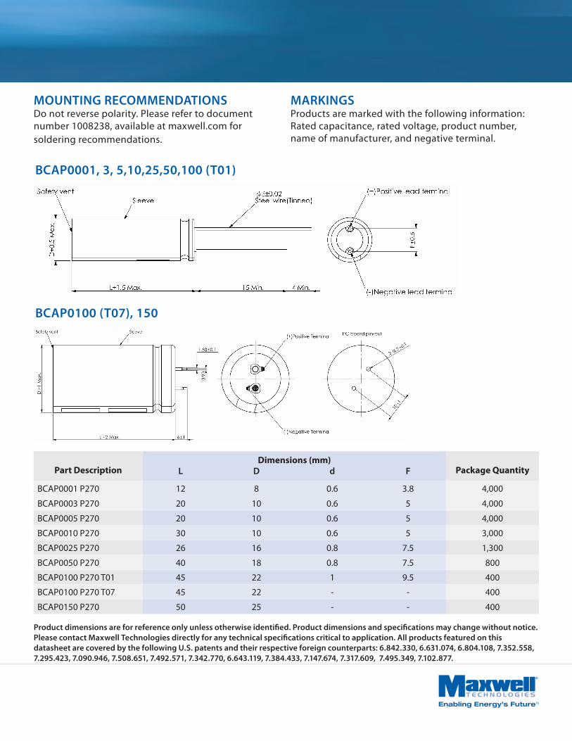
Part DescriptionDimensions (mm)
Package QuantityL D d F
BCAP0001 P270 12 8 0.6 3.8 4,000
BCAP0003 P270 20 10 0.6 5 4,000
BCAP0005 P270 20 10 0.6 5 4,000
BCAP0010 P270 30 10 0.6 5 3,000
BCAP0025 P270 26 16 0.8 7.5 1,300
BCAP0050 P270 40 18 0.8 7.5 800
BCAP0100 P270 T01 45 22 1 9.5 400
BCAP0100 P270 T07 45 22 - - 400
BCAP0150 P270 50 25 - - 400
Product dimensions are for reference only unless otherwise identified. Product dimensions and specifications may change without notice.Please contact Maxwell Technologies directly for any technical specifications critical to application. All products featured on this datasheet are covered by the following U.S. patents and their respective foreign counterparts: 6.842.330, 6.631.074, 6.804.108, 7.352.558, 7.295.423, 7.090.946, 7.508.651, 7.492.571, 7.342.770, 6.643.119, 7.384.433, 7.147.674, 7.317.609, 7.495.349, 7.102.877.
BCAP0001, 3, 5,10,25,50,100 (T01)
BCAP0100 (T07), 150
MOUNTING RECOMMENDATIONSDo not reverse polarity. Please refer to document number 1008238, available at maxwell.com for soldering recommendations.
MARKINGSProducts are marked with the following information: Rated capacitance, rated voltage, product number, name of manufacturer, and negative terminal.
Page 8
Maxwell Technologies, Inc.Global Headquarters5271 Viewridge Court, Suite 100San Diego, CA 92123USATel: +1 858 503 3300Fax: +1 858 503 3301
Maxwell Technologies SACH-1728 RossensSwitzerlandTel: +41 (0)26 411 85 00Fax: +41 (0)26 411 85 05
Maxwell Technologies, GmbHBrucker Strasse 21D-82205 GilchingGermanyTel: +49 (0)8105 24 16 16Fax: +49 (0)8105 24 16 19
Maxwell Technologies, Inc.Shanghai Representative Office13E, CR Times Square500 Zhangyang Road, PudongShanghai 200122, P.R. ChinaTel: +86 21 5836 8780Fax: +86 21 5836 8790
DATASHEET HC SERIES ULTRACAPACITORS


![Automotive Market Perspective of Ultracapacitors[1]](https://static.documents.pub/doc/80x56/577d244a1a28ab4e1e9c1aa5/automotive-market-perspective-of-ultracapacitors1.jpg)


