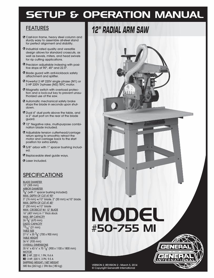
THANK YOU for choosing this General® International radial Saw. This
saw has been carefully tested and inspected before shipment and if properly used and maintained, will provide you with years of reliable service. To ensure optimum performance and trouble-free operation, and to get the most from your investment, please take the time to read this manual before assembling, installing and operating the unit. The manual’s purpose is to familiarize you with the safe operation, basic function, and features of this saw as well as the set-up, maintenance and identification of its parts and components. This manual is not intended as a substitute for formal woodworking instruction, nor to offer the user instruction in the craft of woodworking. If you are not sure about the safety of performing a certain operation or procedure, do not proceed until you can confirm, from knowledgeable and qualified sources, that it is safe to do so. Once you’ve read through these instructions, keep this manual handy for future reference.
GENERAL INTERNATIONAL 8360 Champ-d’Eau, Montréal (Québec) Canada H1P 1Y3
RULES FOR SAFE OPERATION1. Do not operate the saw when tired, distracted, or under the effects of drugs, alcohol or anymedication that impairs reflexes or alertness. 2. The working area should be well lit, clean and free of debris.3. Keep children and visitors at a safe distance when the saw is in operation; do not permit them tooperate the saw. 4. Childproof and tamper proof your shop and all machinery with locks, master electrical switchesand switch keys, to prevent unauthorized or unsupervised use. 5. Stay alert! Give your work your undivided attention. Even a momentary distraction can lead toserious injury. 6. Fine particulate dust is a carcinogen that can be hazardous to health. Work in a well-ventilatedarea and whenever possible use a dust collector and wear eye, ear and respiratory protection devices. 7. Do not wear loose clothing, gloves, bracelets, necklaces or other jewelry while the saw is inoperation. Wear protective hair covering to contain long hair and wear non-slip footwear. 8. Be sure that adjusting wrenches, tools, drinks and other clutter are removed from the machineand/or the feed table surface before operating. 9. Keep hands well away from the blade and all moving parts. Use a brush, not hands, to clear awaychips and dust. 10. Be sure that the blade is securely installed and in proper cutting direction before operation.11. Be sure the blade has gained full operating speed before beginning to cut.12. Always use a clean, properly sharpened blade. Dirty or dull blades are unsafe and can lead toaccidents. 13. If using a power feeder, stop the feeder before stopping the table saw.14. Do not push or force stock into the blade. The saw will perform better and more safely whenworking at the rate for which it was designed. 15. Use suitable support when cutting stock that does not have a flat surface. Always hold stockfirmly against the fence when ripping, or against the miter gauge when cross-cutting. 16. To minimize risk of injury in the event of workpiece kickback, never stand directly in-line with theblade or in the potential kickback path of the work piece. 17. Avoid working from awkward or off balance positions. Do not overreach while cutting; keep bothfeet on floor. Never lean over or reach over the blade and never pull the work piece over the blade from behind. Use out feed support or have an assistant help when ripping long material. 18. Keep blade guards in place and in working order. If a guard must be removed for maintenance orcleaning, be sure it is properly reattached before using the tool again. 19. Never leave the machine running with the power on when not in operation.
20. Use of parts and accessories NOT recommended by GENERAL INTERNATIONAL may result inequipment malfunction or risk of injury. 21. Never stand on machinery. Serious injury could result if the tool is tipped over or if the blade isunintentionally contacted. 22. Always disconnect tool from power before servicing or changing accessories such as blades, orbefore performing any maintenance, cleaning or adjustments, or if the machine will be left unattended. 23. Make sure that switch is in "OFF" position before plugging in the power cord.24. Make sure the tool is properly grounded. If equipped with a 3-prong plug it should be used with athree-pole receptacle. Never remove the third prong. 25. Do not use this saw for other than its intended use. If used for other purposes, GENERALRINTERNATIONAL disclaims any real implied warranty and holds itself harmless for any injury, which may result from that use. 5
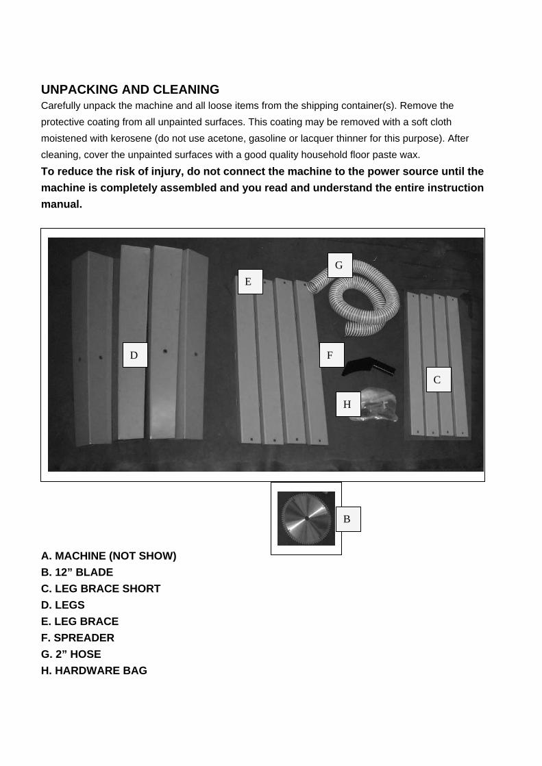
UNPACKING AND CLEANINGCarefully unpack the machine and all loose items from the shipping container(s). Remove the protective coating from all unpainted surfaces. This coating may be removed with a soft cloth moistened with kerosene (do not use acetone, gasoline or lacquer thinner for this purpose). After cleaning, cover the unpainted surfaces with a good quality household floor paste wax.
To reduce the risk of injury, do not connect the machine to the power source until the machine is completely assembled and you read and understand the entire instruction manual.
A. MACHINE (NOT SHOW) B. 12” BLADE C. LEG BRACE SHORT D. LEGS E. LEG BRACE F. SPREADER G. 2” HOSE H. HARDWARE BAG
C
D
E
F
G
H
B
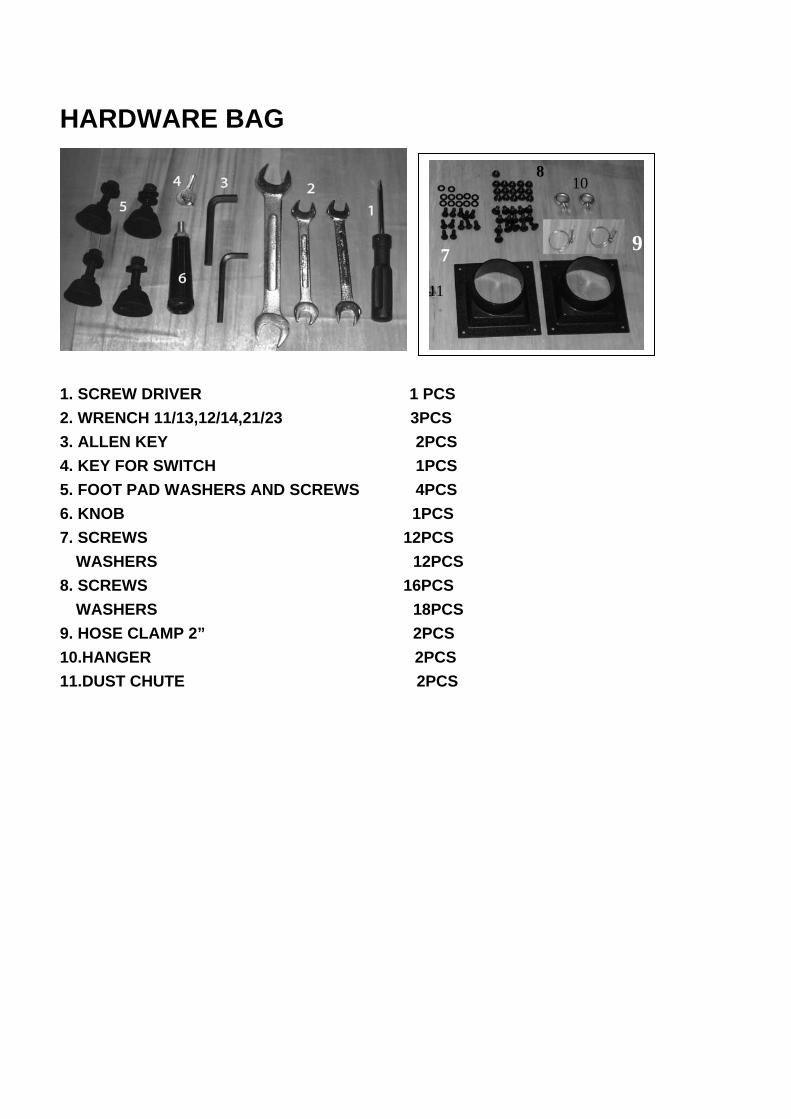
HARDWARE BAG
1. SCREW DRIVER 1 PCS 2. WRENCH 11/13,12/14,21/23 3PCS 3. ALLEN KEY 2PCS 4. KEY FOR SWITCH 1PCS 5. FOOT PAD WASHERS AND SCREWS 4PCS 6. KNOB 1PCS 7. SCREWS 12PCS
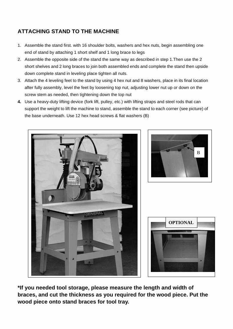
1. Assemble the stand first. with 16 shoulder bolts, washers and hex nuts, begin assembling oneend of stand by attaching 1 short shelf and 1 long brace to legs
2. Assemble the opposite side of the stand the same way as described in step 1.Then use the 2short shelves and 2 long braces to join both assembled ends and complete the stand then upsidedown complete stand in leveling place tighten all nuts.
3. Attach the 4 leveling feet to the stand by using 4 hex nut and 8 washers, place in its final locationafter fully assembly, level the feet by loosening top nut, adjusting lower nut up or down on thescrew stem as needed, then tightening down the top nut
4. Use a heavy-duty lifting device (fork lift, pulley, etc.) with lifting straps and steel rods that cansupport the weight to lift the machine to stand, assemble the stand to each corner (see picture) ofthe base underneath. Use 12 hex head screws & flat washers (B)
*If you needed tool storage, please measure the length and width ofbraces, and cut the thickness as you required for the wood piece. Put the wood piece onto stand braces for tool tray.
OPTIONAL
B
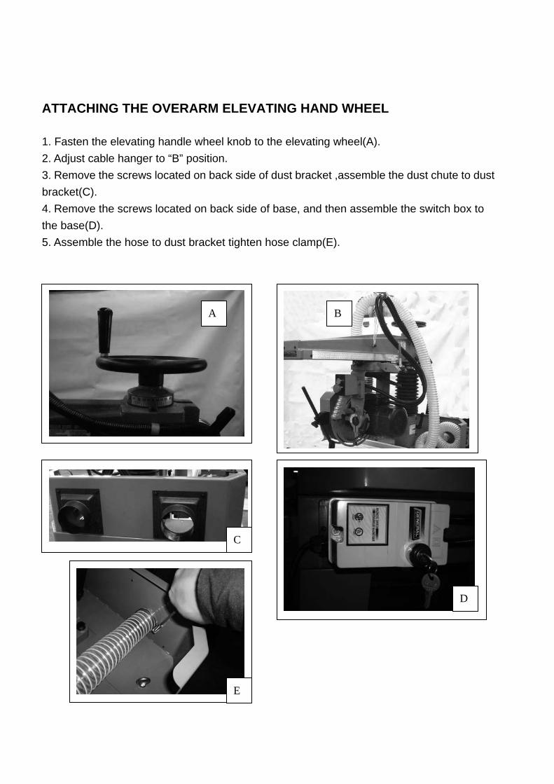
ATTACHING THE OVERARM ELEVATING HAND WHEEL
1. Fasten the elevating handle wheel knob to the elevating wheel(A).2. Adjust cable hanger to “B” position.3. Remove the screws located on back side of dust bracket ,assemble the dust chute to dustbracket(C). 4. Remove the screws located on back side of base, and then assemble the switch box tothe base(D). 5. Assemble the hose to dust bracket tighten hose clamp(E).
B A
C
D
E
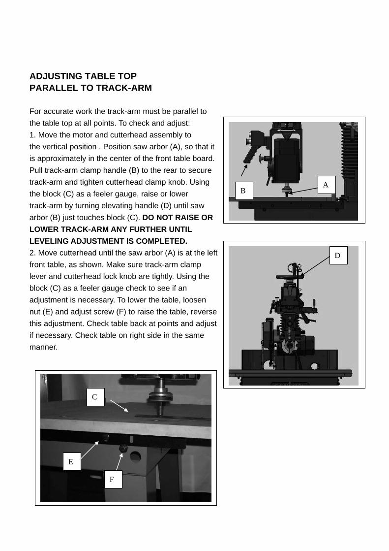
ADJUSTING TABLE TOP PARALLEL TO TRACK-ARM
For accurate work the track-arm must be parallel to the table top at all points. To check and adjust: 1. Move the motor and cutterhead assembly tothe vertical position . Position saw arbor (A), so that it is approximately in the center of the front table board. Pull track-arm clamp handle (B) to the rear to secure track-arm and tighten cutterhead clamp knob. Using the block (C) as a feeler gauge, raise or lower track-arm by turning elevating handle (D) until saw arbor (B) just touches block (C). DO NOT RAISE OR LOWER TRACK-ARM ANY FURTHER UNTIL LEVELING ADJUSTMENT IS COMPLETED. 2. Move cutterhead until the saw arbor (A) is at the leftfront table, as shown. Make sure track-arm clamp lever and cutterhead lock knob are tightly. Using the block (C) as a feeler gauge check to see if an adjustment is necessary. To lower the table, loosen nut (E) and adjust screw (F) to raise the table, reverse this adjustment. Check table back at points and adjust if necessary. Check table on right side in the same manner.
A B
C
D
E
F
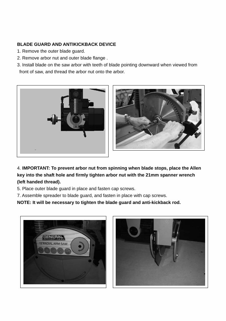
BLADE GUARD AND ANTIKICKBACK DEVICE 1. Remove the outer blade guard.2. Remove arbor nut and outer blade flange .3. Install blade on the saw arbor with teeth of blade pointing downward when viewed fromfront of saw, and thread the arbor nut onto the arbor.
4. IMPORTANT: To prevent arbor nut from spinning when blade stops, place the Allenkey into the shaft hole and firmly tighten arbor nut with the 21mm spanner wrench (left handed thread). 5. Place outer blade guard in place and fasten cap screws.7. Assemble spreader to blade guard, and fasten in place with cap screws.NOTE: It will be necessary to tighten the blade guard and anti-kickback rod.
A
B
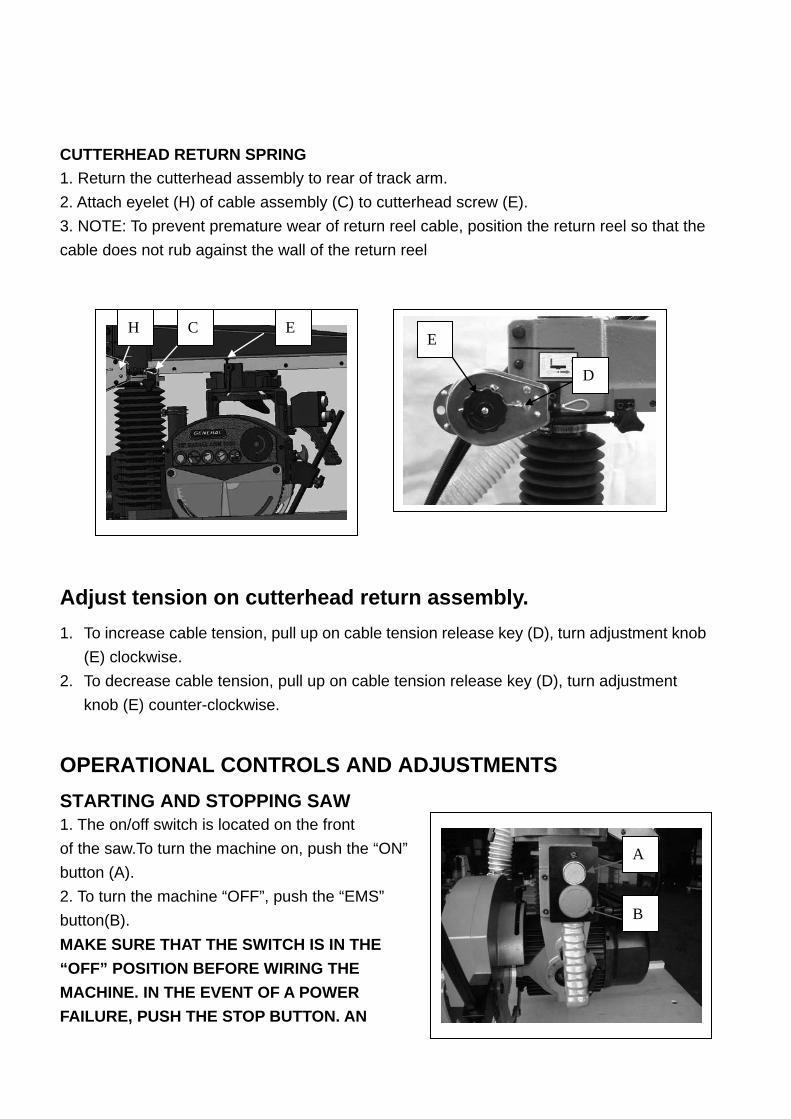
CUTTERHEAD RETURN SPRING 1. Return the cutterhead assembly to rear of track arm. 2. Attach eyelet (H) of cable assembly (C) to cutterhead screw (E). 3. NOTE: To prevent premature wear of return reel cable, position the return reel so that the cable does not rub against the wall of the return reel
Adjust tension on cutterhead return assembly. 1. To increase cable tension, pull up on cable tension release key (D), turn adjustment knob
(E) clockwise. 2. To decrease cable tension, pull up on cable tension release key (D), turn adjustment
knob (E) counter-clockwise.
OPERATIONAL CONTROLS AND ADJUSTMENTS
STARTING AND STOPPING SAW 1. The on/off switch is located on the front of the saw.To turn the machine on, push the “ON” button (A). 2. To turn the machine “OFF”, push the “EMS” button(B). MAKE SURE THAT THE SWITCH IS IN THE “OFF” POSITION BEFORE WIRING THE MACHINE. IN THE EVENT OF A POWER FAILURE, PUSH THE STOP BUTTON. AN
D
E H C E
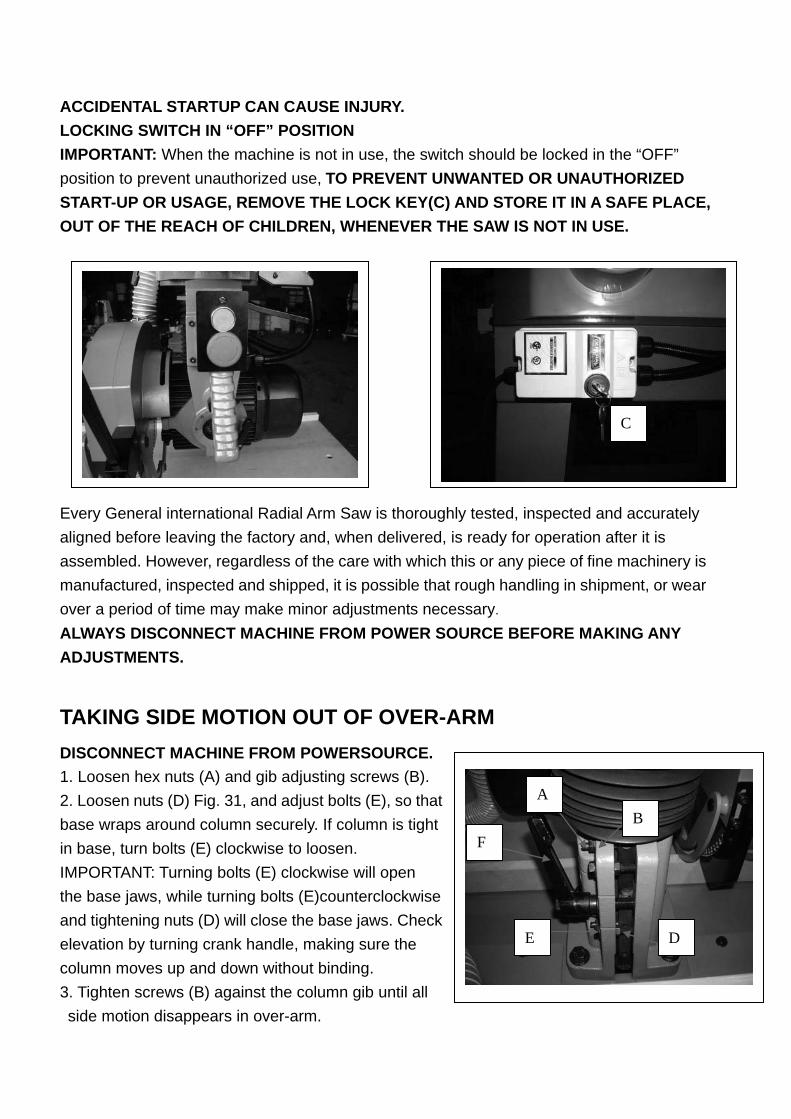
ACCIDENTAL STARTUP CAN CAUSE INJURY. LOCKING SWITCH IN “OFF” POSITION IMPORTANT: When the machine is not in use, the switch should be locked in the “OFF” position to prevent unauthorized use, TO PREVENT UNWANTED OR UNAUTHORIZED START-UP OR USAGE, REMOVE THE LOCK KEY(C) AND STORE IT IN A SAFE PLACE, OUT OF THE REACH OF CHILDREN, WHENEVER THE SAW IS NOT IN USE.
Every General international Radial Arm Saw is thoroughly tested, inspected and accurately aligned before leaving the factory and, when delivered, is ready for operation after it is assembled. However, regardless of the care with which this or any piece of fine machinery is manufactured, inspected and shipped, it is possible that rough handling in shipment, or wear over a period of time may make minor adjustments necessary.
ALWAYS DISCONNECT MACHINE FROM POWER SOURCE BEFORE MAKING ANY ADJUSTMENTS.
TAKING SIDE MOTION OUT OF OVER-ARM DISCONNECT MACHINE FROM POWERSOURCE. 1. Loosen hex nuts (A) and gib adjusting screws (B). 2. Loosen nuts (D) Fig. 31, and adjust bolts (E), so that base wraps around column securely. If column is tight in base, turn bolts (E) clockwise to loosen. IMPORTANT: Turning bolts (E) clockwise will open the base jaws, while turning bolts (E)counterclockwise and tightening nuts (D) will close the base jaws. Check elevation by turning crank handle, making sure the column moves up and down without binding. 3. Tighten screws (B) against the column gib until all side motion disappears in over-arm.
C
B A
D E
F
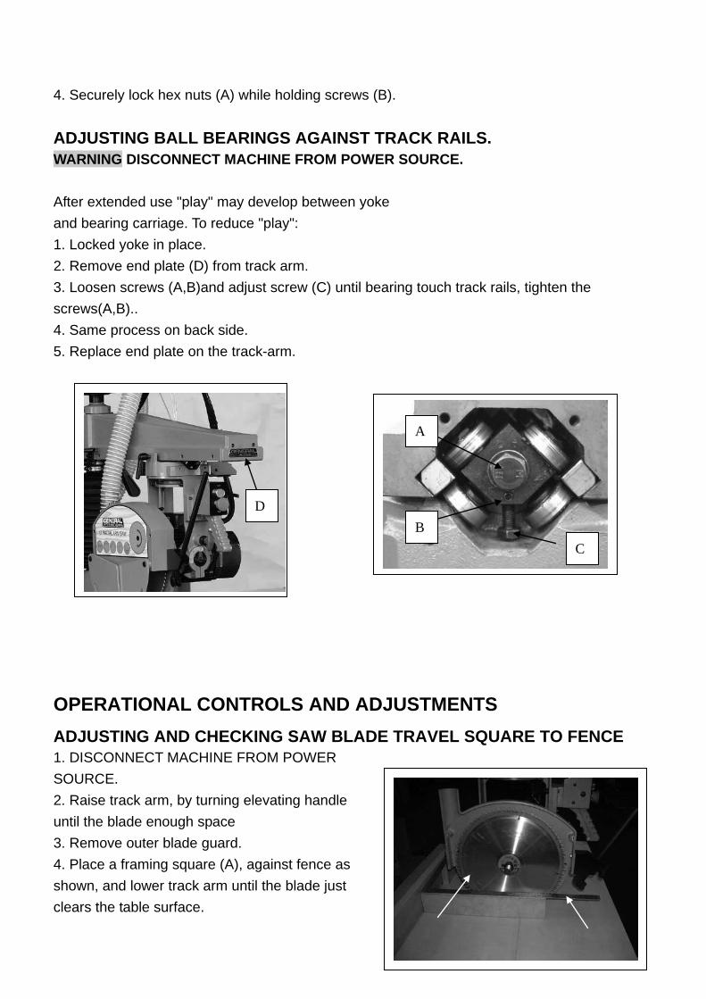
4. Securely lock hex nuts (A) while holding screws (B). ADJUSTING BALL BEARINGS AGAINST TRACK RAILS. WARNING DISCONNECT MACHINE FROM POWER SOURCE. After extended use "play" may develop between yoke and bearing carriage. To reduce "play": 1. Locked yoke in place. 2. Remove end plate (D) from track arm. 3. Loosen screws (A,B)and adjust screw (C) until bearing touch track rails, tighten the screws(A,B).. 4. Same process on back side. 5. Replace end plate on the track-arm.
OPERATIONAL CONTROLS AND ADJUSTMENTS
ADJUSTING AND CHECKING SAW BLADE TRAVEL SQUARE TO FENCE
1. DISCONNECT MACHINE FROM POWER SOURCE. 2. Raise track arm, by turning elevating handle until the blade enough space 3. Remove outer blade guard. 4. Place a framing square (A), against fence as shown, and lower track arm until the blade just clears the table surface.
D
A
B C
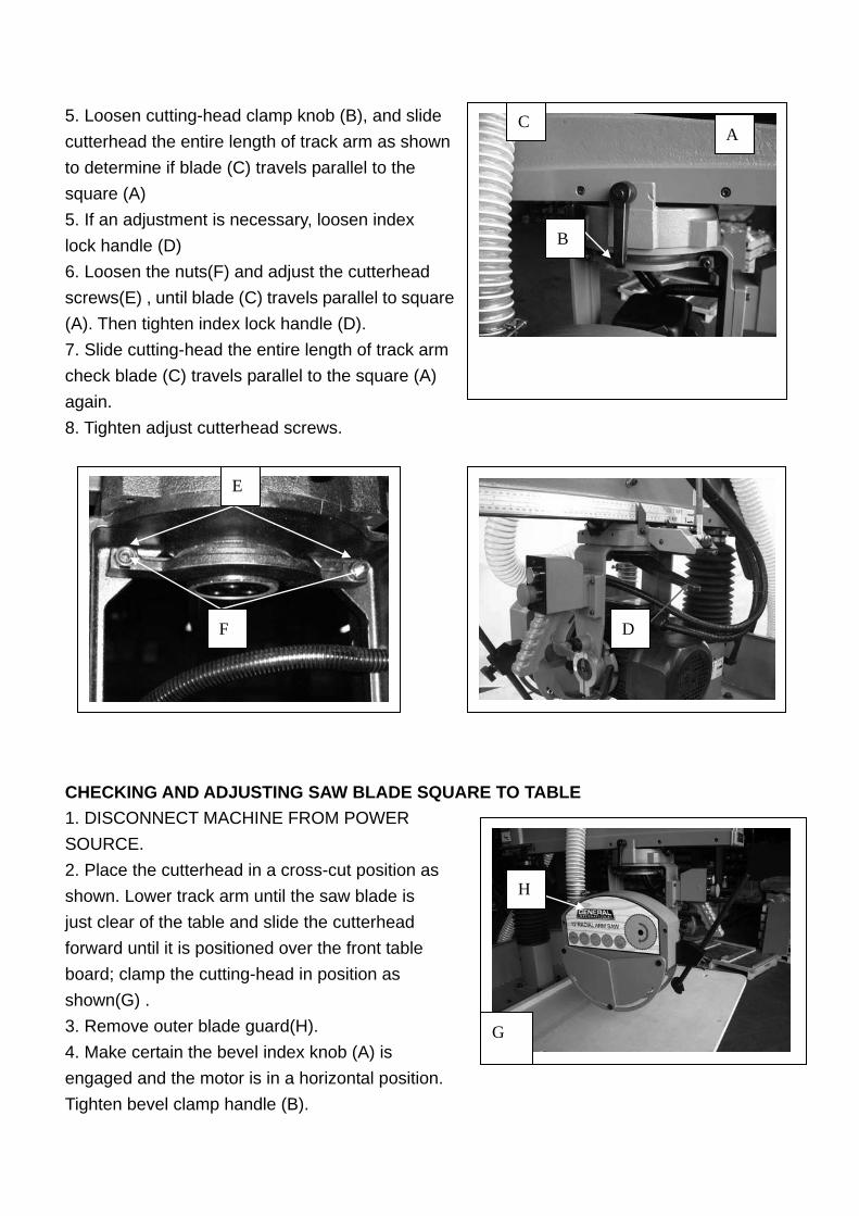
5. Loosen cutting-head clamp knob (B), and slide cutterhead the entire length of track arm as shown to determine if blade (C) travels parallel to the square (A) 5. If an adjustment is necessary, loosen index lock handle (D) 6. Loosen the nuts(F) and adjust the cutterhead screws(E) , until blade (C) travels parallel to square (A). Then tighten index lock handle (D). 7. Slide cutting-head the entire length of track arm check blade (C) travels parallel to the square (A) again. 8. Tighten adjust cutterhead screws.
CHECKING AND ADJUSTING SAW BLADE SQUARE TO TABLE 1. DISCONNECT MACHINE FROM POWER SOURCE. 2. Place the cutterhead in a cross-cut position as shown. Lower track arm until the saw blade is just clear of the table and slide the cutterhead forward until it is positioned over the front table board; clamp the cutting-head in position as shown(G) . 3. Remove outer blade guard(H). 4. Make certain the bevel index knob (A) is engaged and the motor is in a horizontal position. Tighten bevel clamp handle (B).
G
H
A
B
C
D
E
F
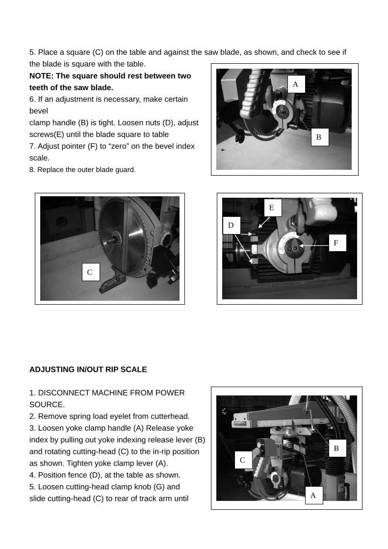
5. Place a square (C) on the table and against the saw blade, as shown, and check to see if the blade is square with the table. NOTE: The square should rest between two teeth of the saw blade. 6. If an adjustment is necessary, make certain bevel clamp handle (B) is tight. Loosen nuts (D), adjust screws(E) until the blade square to table 7. Adjust pointer (F) to “zero” on the bevel index scale. 8. Replace the outer blade guard.
ADJUSTING IN/OUT RIP SCALE 1. DISCONNECT MACHINE FROM POWER SOURCE. 2. Remove spring load eyelet from cutterhead. 3. Loosen yoke clamp handle (A) Release yoke index by pulling out yoke indexing release lever (B) and rotating cutting-head (C) to the in-rip position as shown. Tighten yoke clamp lever (A). 4. Position fence (D), at the table as shown. 5. Loosen cutting-head clamp knob (G) and slide cutting-head (C) to rear of track arm until
A
B
D
A
B C
D
E
F
C
B C
A D
E
G H
K
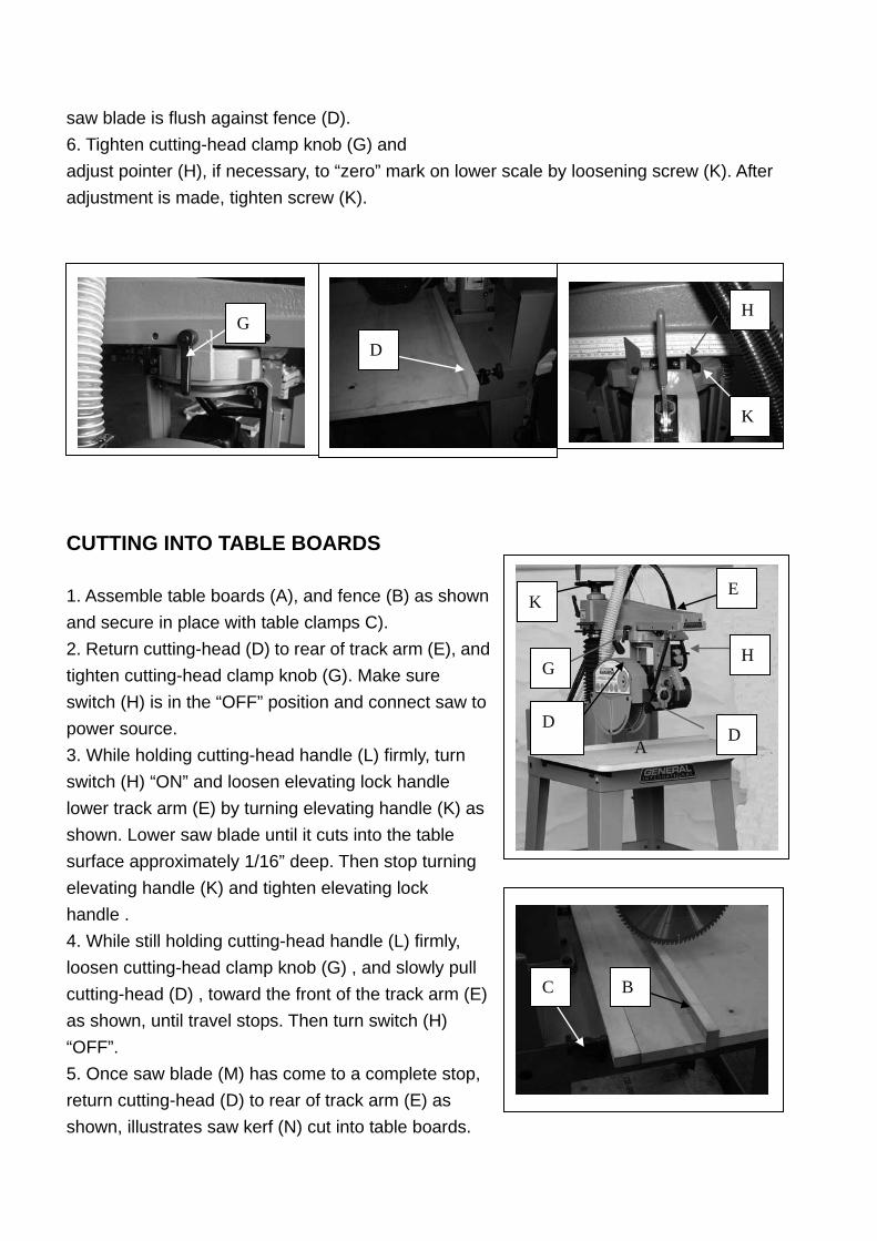
saw blade is flush against fence (D). 6. Tighten cutting-head clamp knob (G) and adjust pointer (H), if necessary, to “zero” mark on lower scale by loosening screw (K). After adjustment is made, tighten screw (K).
CUTTING INTO TABLE BOARDS 1. Assemble table boards (A), and fence (B) as shown and secure in place with table clamps C). 2. Return cutting-head (D) to rear of track arm (E), and tighten cutting-head clamp knob (G). Make sure switch (H) is in the “OFF” position and connect saw to power source. 3. While holding cutting-head handle (L) firmly, turn switch (H) “ON” and loosen elevating lock handle lower track arm (E) by turning elevating handle (K) as shown. Lower saw blade until it cuts into the table surface approximately 1/16” deep. Then stop turning elevating handle (K) and tighten elevating lock handle . 4. While still holding cutting-head handle (L) firmly, loosen cutting-head clamp knob (G) , and slowly pull cutting-head (D) , toward the front of the track arm (E) as shown, until travel stops. Then turn switch (H) “OFF”. 5. Once saw blade (M) has come to a complete stop, return cutting-head (D) to rear of track arm (E) as shown, illustrates saw kerf (N) cut into table boards.
D
G
D
H
K
L
6.same procedure of 45 ゚ right and left cut. IMPORTANT: THE TRACK ARM (E), MUST BE RAISED BEFORE ATTEMPTING TO ROTATE IT. ALSO, THE PROCEDURE
FENCE POSITION 1. A position for 3” capacity 2. B position for 1” capacity 3. C position for In ripping 4. D position for out ripping
A B
C D
A
C
B
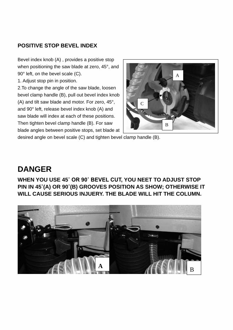
POSITIVE STOP BEVEL INDEX Bevel index knob (A) , provides a positive stop when positioning the saw blade at zero, 45°, and 90° left, on the bevel scale (C). 1. Adjust stop pin in position. 2.To change the angle of the saw blade, loosen bevel clamp handle (B), pull out bevel index knob (A) and tilt saw blade and motor. For zero, 45°, and 90° left, release bevel index knob (A) and saw blade will index at each of these positions. Then tighten bevel clamp handle (B). For saw blade angles between positive stops, set blade at desired angle on bevel scale (C) and tighten bevel clamp handle (B).
DANGER WHEN YOU USE 45˚ OR 90˚ BEVEL CUT, YOU NEET TO ADJUST STOP PIN IN 45˚(A) OR 90˚(B) GROOVES POSITION AS SHOW; OTHERWISE IT WILL CAUSE SERIOUS INJUERY. THE BLADE WILL HIT THE COLUMN.
A B
A
B
C
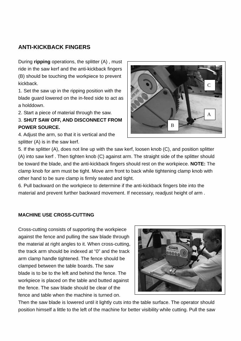
ANTI-KICKBACK FINGERS During ripping operations, the splitter (A) , must ride in the saw kerf and the anti-kickback fingers (B) should be touching the workpiece to prevent kickback. 1. Set the saw up in the ripping position with the blade guard lowered on the in-feed side to act as a holddown. 2. Start a piece of material through the saw. 3. SHUT SAW OFF, AND DISCONNECT FROM POWER SOURCE. 4. Adjust the arm, so that it is vertical and the splitter (A) is in the saw kerf. 5. If the splitter (A), does not line up with the saw kerf, loosen knob (C), and position splitter (A) into saw kerf . Then tighten knob (C) against arm. The straight side of the splitter should be toward the blade, and the anti-kickback fingers should rest on the workpiece. NOTE: The clamp knob for arm must be tight. Move arm front to back while tightening clamp knob with other hand to be sure clamp is firmly seated and tight. 6. Pull backward on the workpiece to determine if the anti-kickback fingers bite into the material and prevent further backward movement. If necessary, readjust height of arm . MACHINE USE CROSS-CUTTING Cross-cutting consists of supporting the workpiece against the fence and pulling the saw blade through the material at right angles to it. When cross-cutting, the track arm should be indexed at “0” and the track arm clamp handle tightened. The fence should be clamped between the table boards. The saw blade is to be to the left and behind the fence. The workpiece is placed on the table and butted against the fence. The saw blade should be clear of the fence and table when the machine is turned on. Then the saw blade is lowered until it lightly cuts into the table surface. The operator should position himself a little to the left of the machine for better visibility while cutting. Pull the saw
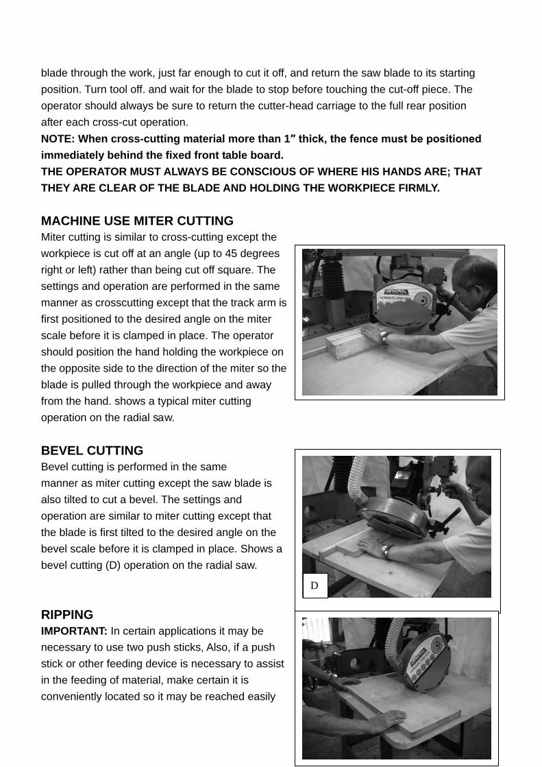
blade through the work, just far enough to cut it off, and return the saw blade to its starting position. Turn tool off. and wait for the blade to stop before touching the cut-off piece. The operator should always be sure to return the cutter-head carriage to the full rear position after each cross-cut operation. NOTE: When cross-cutting material more than 1″ thick, the fence must be positioned immediately behind the fixed front table board. THE OPERATOR MUST ALWAYS BE CONSCIOUS OF WHERE HIS HANDS ARE; THAT THEY ARE CLEAR OF THE BLADE AND HOLDING THE WORKPIECE FIRMLY. MACHINE USE MITER CUTTING Miter cutting is similar to cross-cutting except the workpiece is cut off at an angle (up to 45 degrees right or left) rather than being cut off square. The settings and operation are performed in the same manner as crosscutting except that the track arm is first positioned to the desired angle on the miter scale before it is clamped in place. The operator should position the hand holding the workpiece on the opposite side to the direction of the miter so the blade is pulled through the workpiece and away from the hand. shows a typical miter cutting operation on the radial saw. BEVEL CUTTING Bevel cutting is performed in the same manner as miter cutting except the saw blade is also tilted to cut a bevel. The settings and operation are similar to miter cutting except that the blade is first tilted to the desired angle on the bevel scale before it is clamped in place. Shows a bevel cutting (D) operation on the radial saw. RIPPING IMPORTANT: In certain applications it may be necessary to use two push sticks, Also, if a push stick or other feeding device is necessary to assist in the feeding of material, make certain it is conveniently located so it may be reached easily
D
A
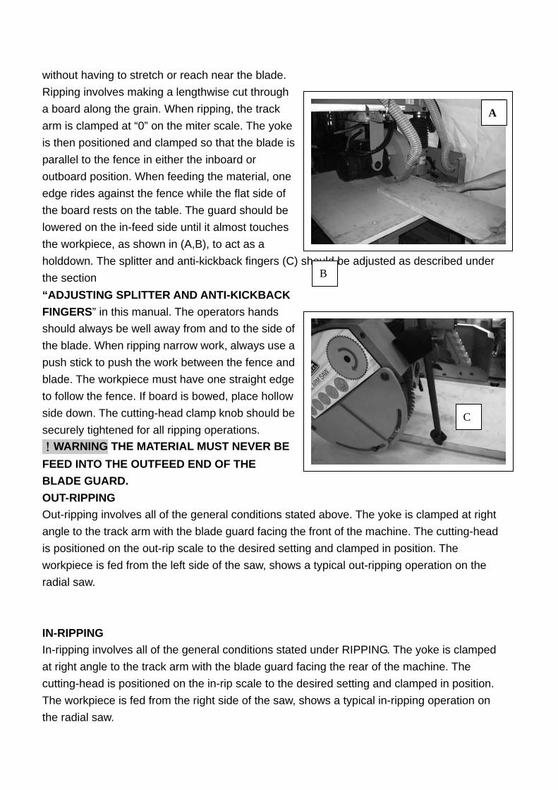
without having to stretch or reach near the blade. Ripping involves making a lengthwise cut through a board along the grain. When ripping, the track arm is clamped at “0” on the miter scale. The yoke is then positioned and clamped so that the blade is parallel to the fence in either the inboard or outboard position. When feeding the material, one edge rides against the fence while the flat side of the board rests on the table. The guard should be lowered on the in-feed side until it almost touches the workpiece, as shown in (A,B), to act as a holddown. The splitter and anti-kickback fingers (C) should be adjusted as described under the section “ADJUSTING SPLITTER AND ANTI-KICKBACK FINGERS” in this manual. The operators hands should always be well away from and to the side of the blade. When ripping narrow work, always use a push stick to push the work between the fence and blade. The workpiece must have one straight edge to follow the fence. If board is bowed, place hollow side down. The cutting-head clamp knob should be securely tightened for all ripping operations. !WARNING THE MATERIAL MUST NEVER BE FEED INTO THE OUTFEED END OF THE BLADE GUARD. OUT-RIPPING Out-ripping involves all of the general conditions stated above. The yoke is clamped at right angle to the track arm with the blade guard facing the front of the machine. The cutting-head is positioned on the out-rip scale to the desired setting and clamped in position. The workpiece is fed from the left side of the saw, shows a typical out-ripping operation on the radial saw. IN-RIPPING In-ripping involves all of the general conditions stated under RIPPING. The yoke is clamped at right angle to the track arm with the blade guard facing the rear of the machine. The cutting-head is positioned on the in-rip scale to the desired setting and clamped in position. The workpiece is fed from the right side of the saw, shows a typical in-ripping operation on the radial saw.
B
C
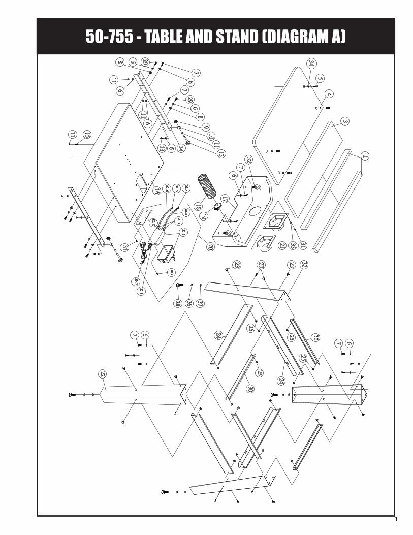
50-755 - TABLE AND STAND (DIAGRAM A)
1
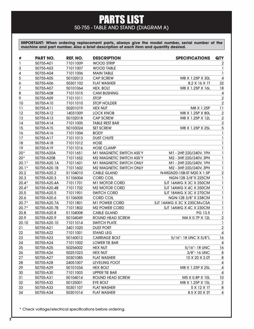
PARTS LIST 50-755 - TABLE AND STAND (DIAGRAM A)
2
# PART NO. REF. NO. DESCRIPTION SPECIFICATIONS QTY1 50755-A01 71011009 WOOD STRIP 23 50755-A03 71011007 WOOD TABLE 14 50755-A04 71011006 MAIN TABLE 15 50755-A05 50102013 CAP SCREW M8 X 1.25P X 30L 46 50755-A06 50301102 FLAT WASHER 8.2 X 16 X 1T 327 50755-A07 50101064 HEX. BOLT M8 X 1.25P X 16L 188 50755-A08 71011015 CAM BUSHING 49 50755-A09 71011011 STOP 210 50755-A10 71011010 STOP HOLDER 211 50755-A11 50201019 HEX NUT M8 X 1.25P 1112 50755-A12 14031009 LOCK KNOB M8 X 1.25P X 80L 213 50755-A13 50102018 CAP SCREW M8 X 1.25P X 12L 214 50755-A14 71011005 TABLE REST BAR 215 50755-A15 50103024 SET SCREW M8 X 1.25P X 25L 516 50755-A16 71011004 BODY 117 50755-A17 71011013 DUST CHUTE 118 50755-A18 71011012 HOSE 119 50755-A19 71011016 HOSE CLAMP 120* 50755-A20A 71011651 M1 MAGNETIC SWITCH ASS’Y M1 - 2HP, 220/240V, 1PH 120* 50755-A20B 71011652 M2 MAGNETIC SWITCH ASS’Y M2 - 3HP, 220/240V, 3PH 120.1* 50755-A20.1A 71011601 M1 MAGNETIC SWITCH ONLY M1 - 2HP, 220/240V, 1PH 120.1* 50755-A20.1B 71011602 M2 MAGNETIC SWITCH ONLY M2 - 3HP, 220/240V, 3PH 120.2 50755-A20.2 51104010 CABLE GLAND N-MGN20-15B-ST M20 X 1.5P 220.3 50755-A20.3 51106004 CORD COIL NGN-12B 3/8”X 225CM 120.4* 50755-A20.4A 71011701 M1 MOTOR CORD SJT 14AWG X 3C X 250CM 120.4* 50755-A20.4B 71011702 M2 MOTOR CORD SJT 14AWG X 4C X 250CM 120.5 50755-A20.5 71011901 SWITCH CORD SJT 18AWG X 3C X 270CM 120.6 50755-A20.6 51106005 CORD COIL NGN-12B 3/8” X 238CM 120.7* 50755-A20.7A 71011801 M1 POWER CORD SJT 14AWG X 3C X 230CM+CSA 120.7* 50755-A20.7B 71011802 M2 POWER CORD SJT 14AWG X 4C X 230CM 120.8 50755-A20.8 51104008 CABLE GLAND PG 13.5 120.9 50755-A20.9 50104049 ROUND HEAD SCREW M4 X 0.7P X 12L 220.10 50755-A20.10 71011014 SWITCH PLATE 121 50755-A21 34011020 DUST PORT 222 50755-A22 71011001 STAND LEG 423 50755-A23 50160012 CARRIAGE BOLT 5/16”- 18 UNC X 5/8”L 1624 50755-A24 71011002 LOWER TIE BAR 425 50755-A25 50256002 HEX NUT 5/16”- 18 UNC 1626 50755-A26 50251023 HEX NUT 3/8”- 16 UNC 827 50755-A27 50301085 FLAT WASHER 10 X 20 X 2.0T 828 50755-A28 24051007 LEVELING FOOT 429 50755-A29 50101034 HEX BOLT M8 X 1.25P X 25L 430 50755-A30 71011003 UPPER TIE BAR 431 50755-A31 50104014 ROUND HEAD SCREW M5 X 0.8P X 10L 1032 50755-A32 50125001 EYE BOLT M8 X 1.25P X 15L 233 50755-A33 50301107 FLAT WASHER 5 X 12 X 1T 834 50755-A34 50301014 FLAT WASHER 8.5 X 20 X 3T 4
IMPORTANT: When ordering replacement parts, always give the model number, serial number of the machine and part number. Also a brief description of each item and quantity desired.
* Check voltage/electrical specifications before ordering.
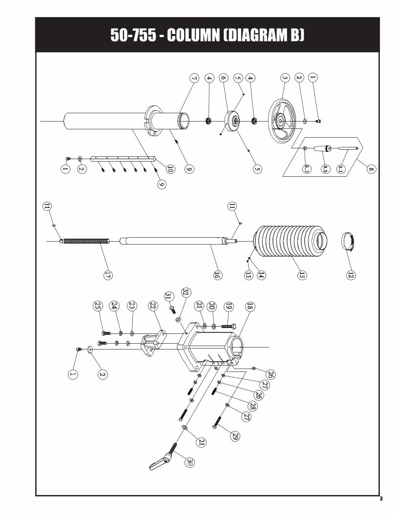
50-755 - COLUMN (DIAGRAM B)
3
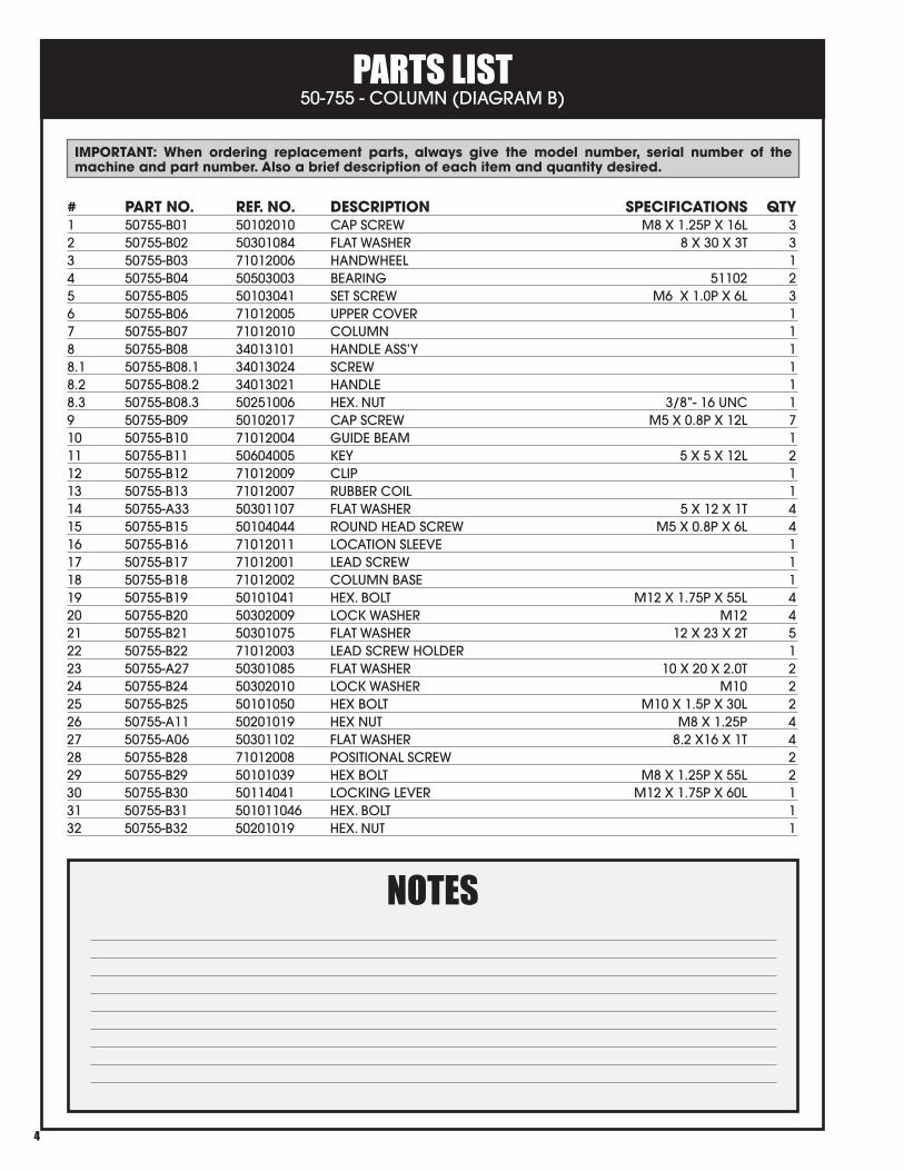
PARTS LIST 50-755 - COLUMN (DIAGRAM B)
4
# PART NO. REF. NO. DESCRIPTION SPECIFICATIONS QTY1 50755-B01 50102010 CAP SCREW M8 X 1.25P X 16L 32 50755-B02 50301084 FLAT WASHER 8 X 30 X 3T 33 50755-B03 71012006 HANDWHEEL 14 50755-B04 50503003 BEARING 51102 25 50755-B05 50103041 SET SCREW M6 X 1.0P X 6L 36 50755-B06 71012005 UPPER COVER 17 50755-B07 71012010 COLUMN 18 50755-B08 34013101 HANDLE ASS’Y 18.1 50755-B08.1 34013024 SCREW 18.2 50755-B08.2 34013021 HANDLE 18.3 50755-B08.3 50251006 HEX. NUT 3/8”- 16 UNC 19 50755-B09 50102017 CAP SCREW M5 X 0.8P X 12L 710 50755-B10 71012004 GUIDE BEAM 111 50755-B11 50604005 KEY 5 X 5 X 12L 212 50755-B12 71012009 CLIP 113 50755-B13 71012007 RUBBER COIL 114 50755-A33 50301107 FLAT WASHER 5 X 12 X 1T 415 50755-B15 50104044 ROUND HEAD SCREW M5 X 0.8P X 6L 416 50755-B16 71012011 LOCATION SLEEVE 117 50755-B17 71012001 LEAD SCREW 118 50755-B18 71012002 COLUMN BASE 119 50755-B19 50101041 HEX. BOLT M12 X 1.75P X 55L 420 50755-B20 50302009 LOCK WASHER M12 421 50755-B21 50301075 FLAT WASHER 12 X 23 X 2T 522 50755-B22 71012003 LEAD SCREW HOLDER 123 50755-A27 50301085 FLAT WASHER 10 X 20 X 2.0T 224 50755-B24 50302010 LOCK WASHER M10 225 50755-B25 50101050 HEX BOLT M10 X 1.5P X 30L 226 50755-A11 50201019 HEX NUT M8 X 1.25P 427 50755-A06 50301102 FLAT WASHER 8.2 X16 X 1T 428 50755-B28 71012008 POSITIONAL SCREW 229 50755-B29 50101039 HEX BOLT M8 X 1.25P X 55L 230 50755-B30 50114041 LOCKING LEVER M12 X 1.75P X 60L 131 50755-B31 501011046 HEX. BOLT 132 50755-B32 50201019 HEX. NUT 1
IMPORTANT: When ordering replacement parts, always give the model number, serial number of the machine and part number. Also a brief description of each item and quantity desired.
NOTES
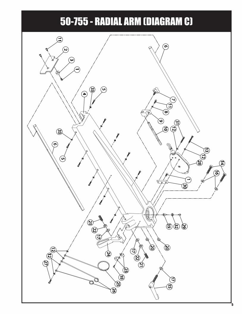
50-755 - RADIAL ARM (DIAGRAM C)
5
211
3
5
68
117
910
14
1
6
5
421
2217
24
1823
1722
21
2019
2526
27
16
1212
20
1517
2812
13
301
1231
2932
33
33
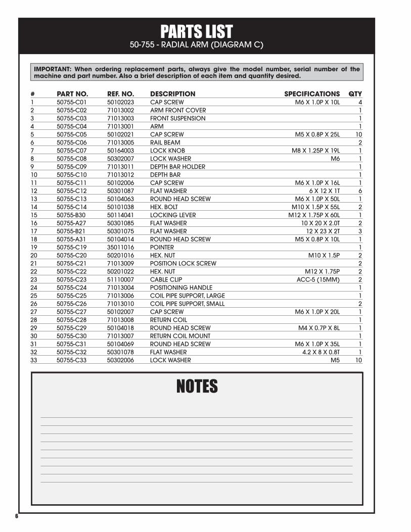
PARTS LIST 50-755 - RADIAL ARM (DIAGRAM C)
6
IMPORTANT: When ordering replacement parts, always give the model number, serial number of the machine and part number. Also a brief description of each item and quantity desired.
# PART NO. REF. NO. DESCRIPTION SPECIFICATIONS QTY1 50755-C01 50102023 CAP SCREW M6 X 1.0P X 10L 42 50755-C02 71013002 ARM FRONT COVER 13 50755-C03 71013003 FRONT SUSPENSION 14 50755-C04 71013001 ARM 15 50755-C05 50102021 CAP SCREW M5 X 0.8P X 25L 106 50755-C06 71013005 RAIL BEAM 27 50755-C07 50164003 LOCK KNOB M8 X 1.25P X 19L 18 50755-C08 50302007 LOCK WASHER M6 19 50755-C09 71013011 DEPTH BAR HOLDER 110 50755-C10 71013012 DEPTH BAR 111 50755-C11 50102006 CAP SCREW M6 X 1.0P X 16L 112 50755-C12 50301087 FLAT WASHER 6 X 12 X 1T 613 50755-C13 50104063 ROUND HEAD SCREW M6 X 1.0P X 50L 114 50755-C14 50101038 HEX. BOLT M10 X 1.5P X 55L 215 50755-B30 50114041 LOCKING LEVER M12 X 1.75P X 60L 116 50755-A27 50301085 FLAT WASHER 10 X 20 X 2.0T 217 50755-B21 50301075 FLAT WASHER 12 X 23 X 2T 318 50755-A31 50104014 ROUND HEAD SCREW M5 X 0.8P X 10L 119 50755-C19 35011016 POINTER 120 50755-C20 50201016 HEX. NUT M10 X 1.5P 221 50755-C21 71013009 POSITION LOCK SCREW 222 50755-C22 50201022 HEX. NUT M12 X 1.75P 223 50755-C23 51110007 CABLE CLIP ACC-5 (15MM) 224 50755-C24 71013004 POSITIONING HANDLE 125 50755-C25 71013006 COIL PIPE SUPPORT, LARGE 126 50755-C26 71013010 COIL PIPE SUPPORT, SMALL 227 50755-C27 50102007 CAP SCREW M6 X 1.0P X 20L 128 50755-C28 71013008 RETURN COIL 129 50755-C29 50104018 ROUND HEAD SCREW M4 X 0.7P X 8L 130 50755-C30 71013007 RETURN COIL MOUNT 131 50755-C31 50104069 ROUND HEAD SCREW M6 X 1.0P X 35L 132 50755-C32 50301078 FLAT WASHER 4.2 X 8 X 0.8T 133 50755-C33 50302006 LOCK WASHER M5 10
NOTES
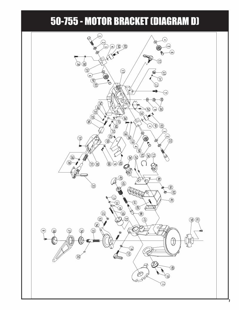
50-755 - MOTOR BRACKET (DIAGRAM D)
7
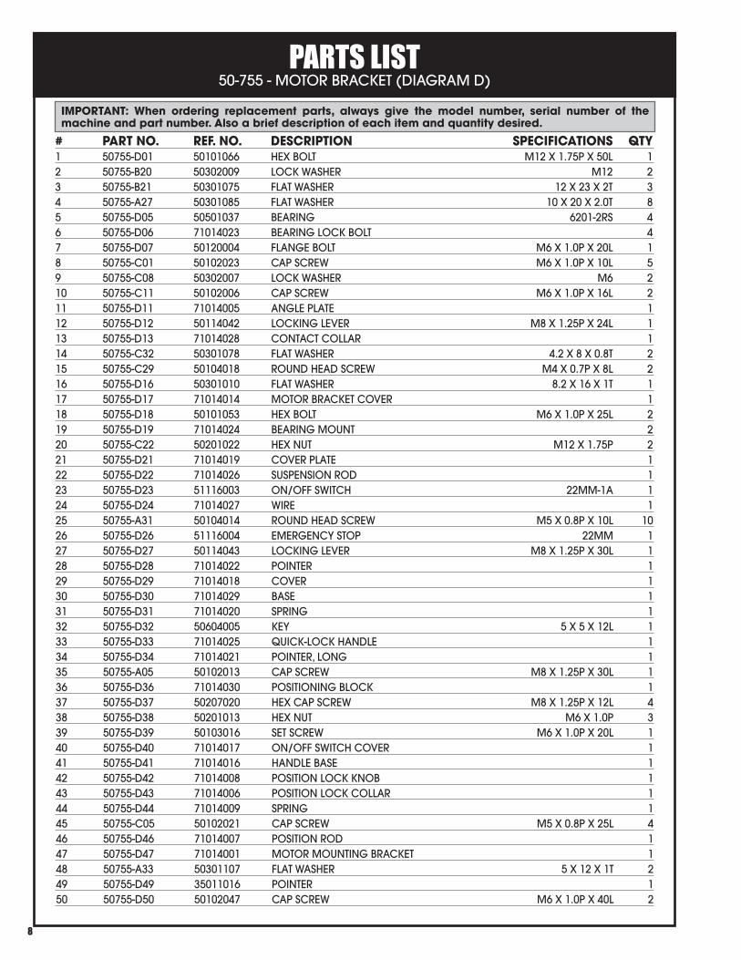
PARTS LIST 50-755 - MOTOR BRACKET (DIAGRAM D)
8
# PART NO. REF. NO. DESCRIPTION SPECIFICATIONS QTY1 50755-D01 50101066 HEX BOLT M12 X 1.75P X 50L 12 50755-B20 50302009 LOCK WASHER M12 23 50755-B21 50301075 FLAT WASHER 12 X 23 X 2T 34 50755-A27 50301085 FLAT WASHER 10 X 20 X 2.0T 85 50755-D05 50501037 BEARING 6201-2RS 46 50755-D06 71014023 BEARING LOCK BOLT 47 50755-D07 50120004 FLANGE BOLT M6 X 1.0P X 20L 18 50755-C01 50102023 CAP SCREW M6 X 1.0P X 10L 59 50755-C08 50302007 LOCK WASHER M6 210 50755-C11 50102006 CAP SCREW M6 X 1.0P X 16L 211 50755-D11 71014005 ANGLE PLATE 112 50755-D12 50114042 LOCKING LEVER M8 X 1.25P X 24L 113 50755-D13 71014028 CONTACT COLLAR 114 50755-C32 50301078 FLAT WASHER 4.2 X 8 X 0.8T 215 50755-C29 50104018 ROUND HEAD SCREW M4 X 0.7P X 8L 216 50755-D16 50301010 FLAT WASHER 8.2 X 16 X 1T 117 50755-D17 71014014 MOTOR BRACKET COVER 118 50755-D18 50101053 HEX BOLT M6 X 1.0P X 25L 219 50755-D19 71014024 BEARING MOUNT 220 50755-C22 50201022 HEX NUT M12 X 1.75P 221 50755-D21 71014019 COVER PLATE 122 50755-D22 71014026 SUSPENSION ROD 123 50755-D23 51116003 ON/OFF SWITCH 22MM-1A 124 50755-D24 71014027 WIRE 125 50755-A31 50104014 ROUND HEAD SCREW M5 X 0.8P X 10L 1026 50755-D26 51116004 EMERGENCY STOP 22MM 127 50755-D27 50114043 LOCKING LEVER M8 X 1.25P X 30L 128 50755-D28 71014022 POINTER 129 50755-D29 71014018 COVER 130 50755-D30 71014029 BASE 131 50755-D31 71014020 SPRING 132 50755-D32 50604005 KEY 5 X 5 X 12L 133 50755-D33 71014025 QUICK-LOCK HANDLE 134 50755-D34 71014021 POINTER, LONG 135 50755-A05 50102013 CAP SCREW M8 X 1.25P X 30L 136 50755-D36 71014030 POSITIONING BLOCK 137 50755-D37 50207020 HEX CAP SCREW M8 X 1.25P X 12L 438 50755-D38 50201013 HEX NUT M6 X 1.0P 339 50755-D39 50103016 SET SCREW M6 X 1.0P X 20L 140 50755-D40 71014017 ON/OFF SWITCH COVER 141 50755-D41 71014016 HANDLE BASE 142 50755-D42 71014008 POSITION LOCK KNOB 143 50755-D43 71014006 POSITION LOCK COLLAR 144 50755-D44 71014009 SPRING 145 50755-C05 50102021 CAP SCREW M5 X 0.8P X 25L 446 50755-D46 71014007 POSITION ROD 147 50755-D47 71014001 MOTOR MOUNTING BRACKET 148 50755-A33 50301107 FLAT WASHER 5 X 12 X 1T 249 50755-D49 35011016 POINTER 150 50755-D50 50102047 CAP SCREW M6 X 1.0P X 40L 2
IMPORTANT: When ordering replacement parts, always give the model number, serial number of the machine and part number. Also a brief description of each item and quantity desired.
PARTS LIST 50-755 - MOTOR BRACKET (DIAGRAM D) - CONTINUED
9
# PART NO. REF. NO. DESCRIPTION SPECIFICATIONS QTY51 50755-D51 71014003 FRONT CENTRAL SHAFT 152 50755-A11 50201019 HEX NUT M8 X 1.25P 253 50755-D53 50103043 SET SCREW M8 X 1.25P X 35L 254 50755-D54 71014013 ADJUSTING BLOCK 155 50755-D55 71014012 LOCK ROD 156 50755-D56 71014011 LOCK HANDLE UPPER BASE 157 50755-D57 71014002 LOCK HANDLE 158 50755-D58 71014010 LOCK HANDLE LOWER BASE 159 50755-D59 71014015 ANGLE PLATE 160 50755-D60 71014004 REAR CENTRAL SHAFT 161 50755-D61 50102023 CAP SCREW M6 X 1.0P X 12L 362 50755-B15 50104044 ROUND HEAD SCREW M5 X 0.8P X 6L 263 50755-D63 71014031 BEARING LOCK SCREW 464 50755-D64 50501055 BEARING 5201-ZZ 465 50755-D65 50201021 HEX. NUT M5 X 0.8P 166 50755-D66 50303003 LOCK WASHER M5 167 50755-D67 71014035 POSITION ROD 168 50755-D68 50102056 CAP SCREW M6 X 1 X 14L 1
IMPORTANT: When ordering replacement parts, always give the model number, serial number of the machine and part number. Also a brief description of each item and quantity desired.
NOTES
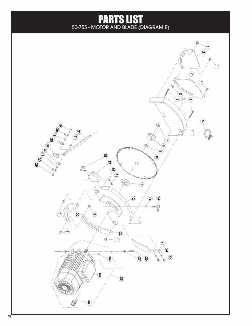
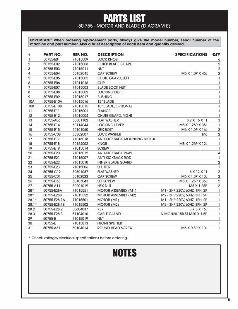
PARTS LIST 50-755 - MOTOR AND BLADE (DIAGRAM E)
10
1
12
2
34 5 4
6
78
910
11
12 13 14
1617
18
2425
221
2627
28.1
322
1
1
15
23
1
1320
21
2013
1920
2920
30
31
28
28.2
28.3
PARTS LIST 50-755 - MOTOR AND BLADE (DIAGRAM E)
11
IMPORTANT: When ordering replacement parts, always give the model number, serial number of the machine and part number. Also a brief description of each item and quantity desired.
# PART NO. REF. NO. DESCRIPTION SPECIFICATIONS QTY1 50755-E01 71015009 LOCK KNOB 62 50755-E02 71015008 OUTER BLADE GUARD 23 50755-E03 71015011 NUT 24 50755-E04 50102045 CAP SCREW M6 X 1.0P X 45L 25 50755-E05 71015005 CHUTE GUARD, LEFT 16 50755-E06 71011016 CLIP 17 50755-E07 71015003 BLADE LOCK NUT 18 50755-E08 71015002 LOCKING DISC 19 50755-E09 71015017 BUSHING 110A 50755-E10A 71015016 12” BLADE 110B 50755-E10B 71015015 10” BLADE, OPTIONAL 111 50755-E11 71015001 FLANGE 112 50755-E12 71015004 CHUTE GUARD, RIGHT 113 50755-A06 50301102 FLAT WASHER 8.2 X 16 X 1T 314 50755-E14 50114044 LOCKING LEVER M8 X 1.25P X 35L 115 50755-E15 50101060 HEX BOLT M6 X 1.0P X 16L 216 50755-C08 50302007 LOCK WASHER M6 217 50755-E17 71015018 ANTI-KICKBACK MOUNTING BLOCK 118 50755-E18 50164002 KNOB M8 X 1.25P X 12L 119 50755-E19 71015014 SCREW 120 50755-E20 71015012 ANTI-KICKBACK PAWL 421 50755-E21 71015007 ANTI-KICKBACK ROD 122 50755-E22 71015010 INNER BLADE GUARD 223 50755-E23 71015006 SPLITTER 124 50755-C12 50301087 FLAT WASHER 6 X 12 X 1T 225 50755-C01 50102023 CAP SCREW M6 X 1.0P X 10L 226 50755-D53 50103043 SET SCREW M8 X 1.25P X 35L 227 50755-A11 50201019 HEX NUT M8 X 1.25P 228* 50755-E28A 71015551 MOTOR ASSEMBLY (M1) M1 - 2HP, 220V, 60HZ, 1PH, 2P 128* 50755-E28B 71015552 MOTOR ASSEMBLY (M2) M2 - 3HP, 220V, 60HZ, 3PH, 2P 128.1* 50755-E28.1A 71015501 MOTOR (M1) M1 - 2HP, 220V, 60HZ, 1PH, 2P 128.1* 50755-E28.1B 71015502 MOTOR (M2) M2 - 3HP, 220V, 60HZ, 3PH, 2P 128.2 50755-E28.2 50604037 KEY 5 X 5 X 16L 128.3 50755-E28.3 51104010 CABLE GLAND N-MGN20-15B-ST M20 X 1.5P 129 50755-E 71015019 NUT 130 50755-E 71015013 FRONT SPLITTER 131 50755-A31 50104014 ROUND HEAD SCREW M5 X 0.8P X 10L 1
NOTES* Check voltage/electrical specifications before ordering.