24
Feb 23, 2007 EEE393 Basic Electrical Engin eering K.A.Peker kpeker@ bilkent.edu.tr 1 Signals and Systems Introduction EEE393 Basic Electrical Engineering K.A.Peker Bilkent University
| Date post: | 22-Dec-2015 |
| Category: |
Documents |
| View: | 218 times |
| Download: | 1 times |

Feb 23, 2007 EEE393 Basic Electrical Engineering K.A.Peker [email protected]
1
Signals and Systems Introduction
EEE393 Basic Electrical Engineering
K.A.Peker
Bilkent University

Feb 23, 2007 EEE393 Basic Electrical Engineering K.A.Peker [email protected]
2
From
Circuits to
Signals and Systems
Feb 23, 2007 EEE393 Basic Electrical Engineering K.A.Peker [email protected]
3
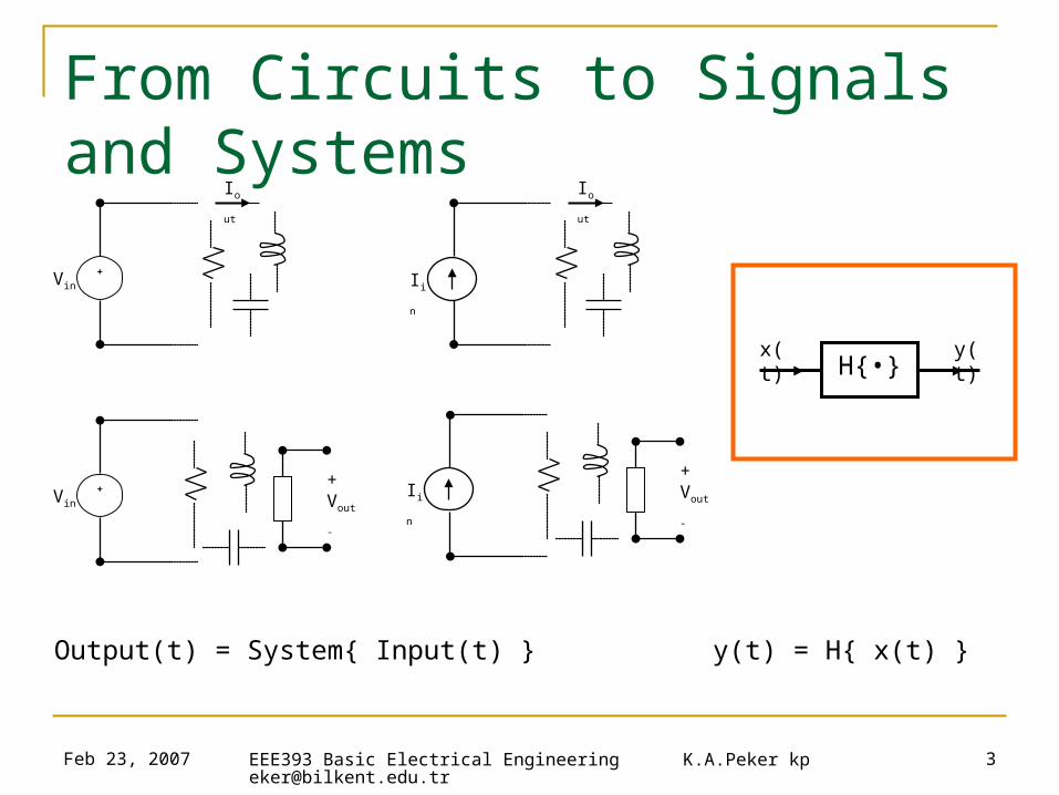
From Circuits to Signals and Systems
Output(t) = System{ Input(t) } y(t) = H{ x(t) }
+Vin
Iout Iout
+VinIin
Iin
+Vout
-
+Vout
-
H{•}x(t) y(t)
Feb 23, 2007 EEE393 Basic Electrical Engineering K.A.Peker [email protected]
4
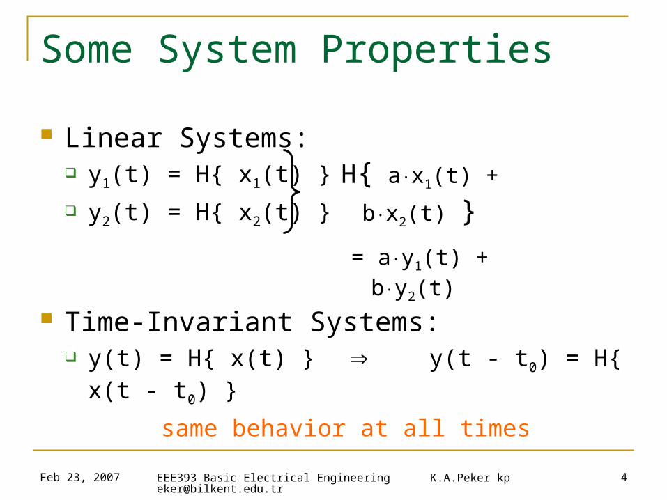
Some System Properties
Linear Systems: y1(t) = H{ x1(t) }
y2(t) = H{ x2(t) }
Time-Invariant Systems: y(t) = H{ x(t) } y(t - t0) = H{ x(t -
t0) }
same behavior at all times
H{ a·x1(t) + b·x2(t) }
= a·y1(t) + b·y2(t)

Feb 23, 2007 EEE393 Basic Electrical Engineering K.A.Peker [email protected]
5
Linear Time Invariant Circuits R, L, C linear, time invariant elements
V = R·i linear, time invariant C and L are also linear, time invariant
(diff. is linear):
R-L-C circuits are also linear, time invariant systems
dt
dvCi 1
1
dt
dvCi 2
2
21
21
21
biaidt
dvCb
dt
dvCa
dt
bvavdC
Feb 23, 2007 EEE393 Basic Electrical Engineering K.A.Peker [email protected]
6
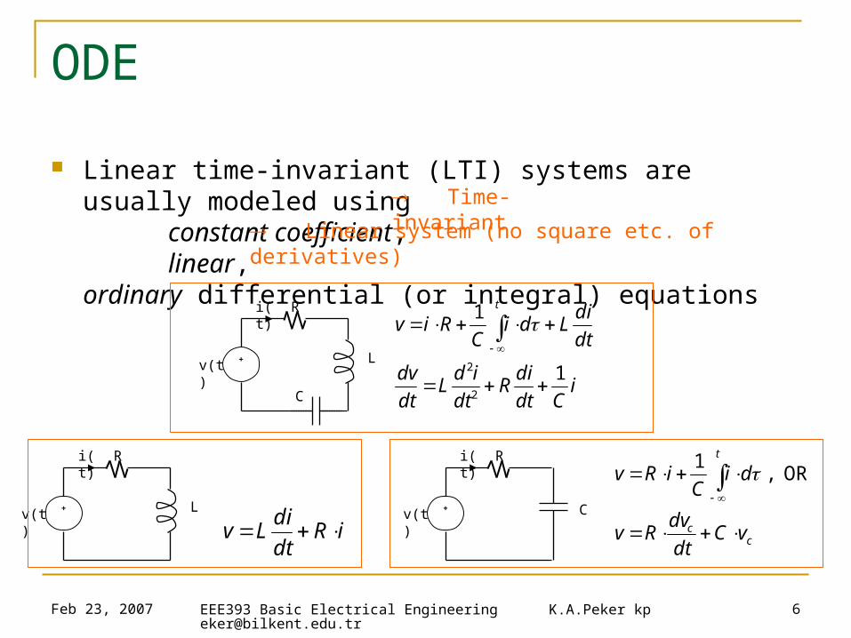
ODE
Linear time-invariant (LTI) systems are usually modeled usingconstant coefficient, linear,
ordinary differential (or integral) equations
Time-invariant
Linear system (no square etc. of derivatives)
+v(t)
R
L
i(t)
Ci
Cdt
diR
dt
idL
dt
dv
dt
diLdi
CRiv
t
1
1
2
2
+v(t)
R
L
i(t)
+v(t)
Ri(t)
C
iRdt
diLv c
c
t
vCdt
dvRv
diC
iRv
OR , 1
Feb 23, 2007 EEE393 Basic Electrical Engineering K.A.Peker [email protected]
7
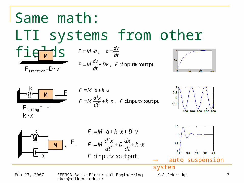
Same math: LTI systems from other fields
MF
Ffriction=D·voutput:input : ,
,
vFDvdt
dvMF
dt
dvaaMF
M F
Fspring= - k·x
k
output:input : ,
2
2
xFxkdt
xdMF
xkaMF
M F
k
D output:input :
2
2
xF
xkdt
dxD
dt
xdMF
vDxkaMF
auto suspension system
Feb 23, 2007 EEE393 Basic Electrical Engineering K.A.Peker [email protected]
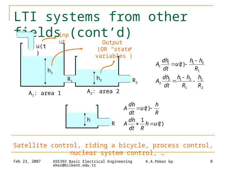
8
Satellite control, riding a bicycle, process control, nuclear system control, …
LTI systems from other fields (cont’d)
A1: area 1
R2R1
A2: area 2
h1
h2
u(t)
2
2
1
2122
1
2111 )(
R
h
R
hh
dt
dhA
R
hhtu
dt
dhA
inputOutput
(OR “state variables”)
Rh
)(1
)(
tuhRdt
dhA
R
htu
dt
dhA
Feb 23, 2007 EEE393 Basic Electrical Engineering K.A.Peker [email protected]
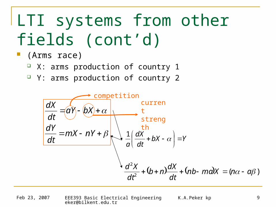
9
LTI systems from other fields (cont’d) (Arms race)
X: arms production of country 1 Y: arms production of country 2
nYmXdt
dY
bXaYdt
dX
)(2
2
anXmanbdt
dXnb
dt
Xd
YbXdt
dX
a
1
competitioncurrent strength

Feb 23, 2007 EEE393 Basic Electrical Engineering K.A.Peker [email protected]
10
LTI systems from other fields (cont’d) (Oligopoly/duopoly) – economics, game theory
Two companies in a market, producing same product
produced) more when declines price ,( ,)(
demand)-(supply volumeproductionfor priceMarket : )(
babaxxp
xxp
product producing ofcost 2,company ,)(
product producing ofcost 1,company ,)(
2company by production of Volume :
1company by production of Volume :
222222
111111
2
1
xcxbxC
xcxbxC
x
x
222212
2
111212
1
11211
)(2
)(1
)()(1 :Profit1
cxbbxaxaxP
cxbbxaxaxP
xCxxpxP
21222
12111
2
2
bbaxaxmdt
dx
bbaxaxmdt
dx
If change in production is proportional to marginal change in profit

Feb 23, 2007 EEE393 Basic Electrical Engineering K.A.Peker [email protected]
11
So…
RLC circuits are
…linear time-invariant systems
…described by linear ordinary differential equations (ODE)
…which are used to model many other systems
in different sciences and engineering fields
In fact, they’re mathematically same as many other
physical/social/economic etc. systems (analogous)
Hence, the math and the techniques we learn here apply to many
other problems in other domains
Feb 23, 2007 EEE393 Basic Electrical Engineering K.A.Peker [email protected]
12
Response of LTI Systems
- Response to complex exponentials
- AC circuit analysis
Feb 23, 2007 EEE393 Basic Electrical Engineering K.A.Peker [email protected]
13
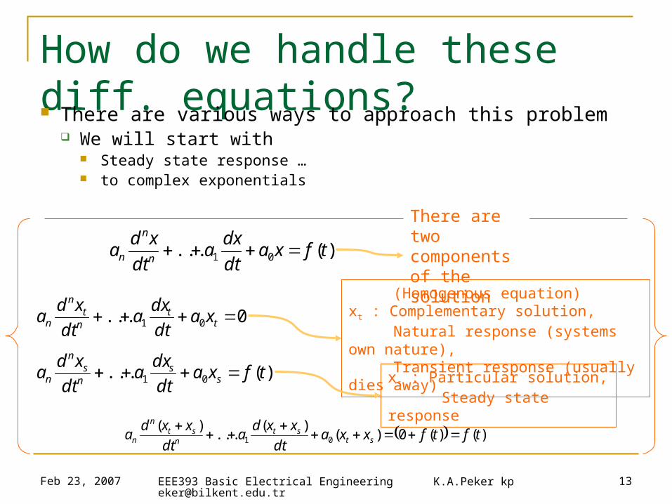
How do we handle these diff. equations? There are various ways to approach this problem
We will start with Steady state response … to complex exponentials
)(... 01 tfxadt
dxa
dt
xda
n
n
n
0... 01 tt
nt
n
n xadt
dxa
dt
xda
There are two components of the solution
(Homogenous equation) xt : Complementary solution, Natural response (systems own nature), Transient response (usually dies away)
)(... 01 tfxadt
dxa
dt
xda s
sns
n
n xs : Particular solution, Steady state response
)()(0)()(
...)(
01 tftfxxadt
xxda
dt
xxda st
stn
stn
n

Feb 23, 2007 EEE393 Basic Electrical Engineering K.A.Peker [email protected]
14
The complex exponential
Everything starts with the simple but important fact that;
Corollaries: If we assume complex exponential input, then
all currents/voltages in an RLC circuit are also complex exponentials
Differential equations become algebraic (polynomial) equations
tsts
esdt
ed
Derivative of a complex exponential is itself, multiplied by a constant
ion)superposit ,(linearity generalin , ,
,ts
i
st
ieXiv
Xeiv
Complex exponentials are eigen functions of LTI systems
Linear systems – vector spaces – basis expansion
Laplace domain – exp(st), Fourier domain – exp(jw)

Feb 23, 2007 EEE393 Basic Electrical Engineering K.A.Peker [email protected]
15
The complex exponential (cont’d) From diff. equations to polynomial equations
0
,
:form in the be tohas
:Assume
2
2
22
2
2
AkXsDXMXs
ekXsDXMXseA
eAFF
ekXsDXMXsekXesDXeMXsF
eXx
xkdt
dxD
dt
xdMF
stst
st
stststst
st
Note:
Complex exp. input Complex exp. output
(works both ways)
Feb 23, 2007 EEE393 Basic Electrical Engineering K.A.Peker [email protected]
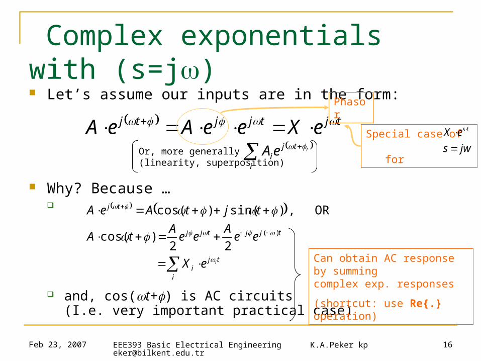
16
Complex exponentials with (s=j) Let’s assume our inputs are in the form:
Why? Because …
and, cos(t+) is AC circuits (I.e. very important practical case)
tjtjjtj eXeeAeA
i
tji
ieA Or, more generally(linearity, superposition)
Special case of for jws
eX ts
tj
ii
tjjtjj
tj
ieX
eeA
eeA
tA
tjtAeA
22)cos(
OR , )sin()cos(
)(
Phasor
Can obtain AC response by summing complex exp. responses
(shortcut: use Re{.} operation)
Feb 23, 2007 EEE393 Basic Electrical Engineering K.A.Peker [email protected]
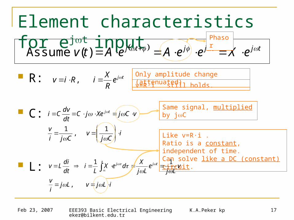
17
Element characteristics for ejt input
R:
C:
L:
tjtjjtj eXeeAeAtv )( AssumePhasor
tjeR
XiRiv ,
Only amplitude change (attenuated)
v=R·i still holds.
iCj
vCji
v
vCjXejCdt
dvCi tj
1 ,
1
Same signal, multiplied by jC
Like v=R·i . Ratio is a constant, independent of time.Can solve like a DC (constant) circuit.
iLjvLji
v
vLj
eLj
XdeX
Li
dt
diLv tjt j
,
11

Feb 23, 2007 EEE393 Basic Electrical Engineering K.A.Peker [email protected]
18
Impedance
For complex exponential v(t), i(t), with frequency
Capacitor characteristics C:
Inductor characteristics L:
and are just like resistance values
(constant ratio), but are complex values
We call this ratio of complex v to i, ( ), “Impedance” (Z)
iCj
v 1
iLjv
Cj1
Lj
i
v
i
v
Feb 23, 2007 EEE393 Basic Electrical Engineering K.A.Peker [email protected]
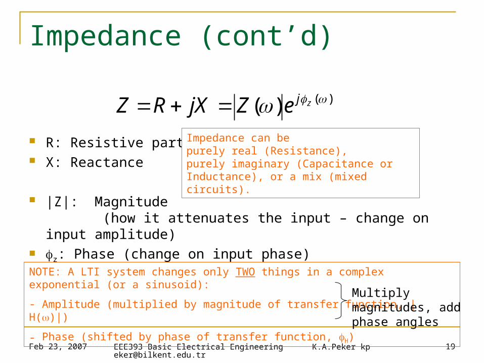
19
Impedance (cont’d)
R: Resistive part X: Reactance
|Z|: Magnitude (how it attenuates the input – change on input amplitude)
z: Phase (change on input phase)
)()( zjeZjXRZ
NOTE: A LTI system changes only TWO things in a complex exponential (or a sinusoid):
- Amplitude (multiplied by magnitude of transfer function, |H()|)
- Phase (shifted by phase of transfer function, H)
Multiply magnitudes, add phase angles
Impedance can be purely real (Resistance), purely imaginary (Capacitance or Inductance), or a mix (mixed circuits).
Feb 23, 2007 EEE393 Basic Electrical Engineering K.A.Peker [email protected]
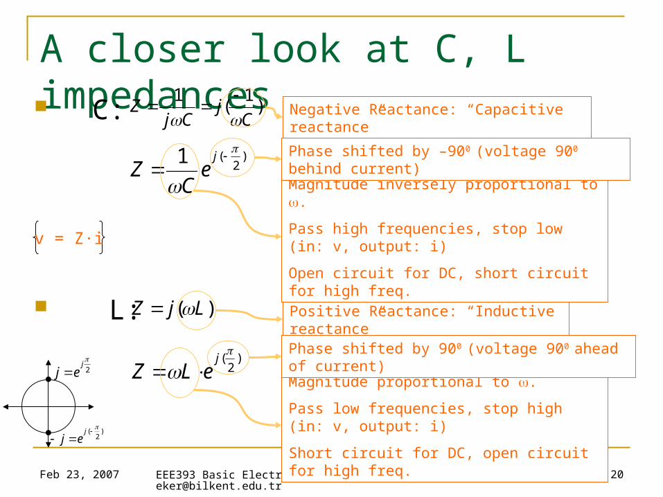
20
A closer look at C, L impedances C:
L:
)1
(1
Cj
CjZ
Negative Reactance: “Capacitive reactance”
)( LjZ Positive Reactance: “Inductive reactance”
)2
(1
je
CZ
)2
(
jeLZ
Magnitude inversely proportional to .
Pass high frequencies, stop low (in: v, output: i)
Open circuit for DC, short circuit for high freq.
Magnitude proportional to .
Pass low frequencies, stop high (in: v, output: i)
Short circuit for DC, open circuit for high freq.
Phase shifted by –900 (voltage 900 behind current)
2
jej
)2
(
jej
Phase shifted by 900 (voltage 900 ahead of current)
v = Z·i
Feb 23, 2007 EEE393 Basic Electrical Engineering K.A.Peker [email protected]
21
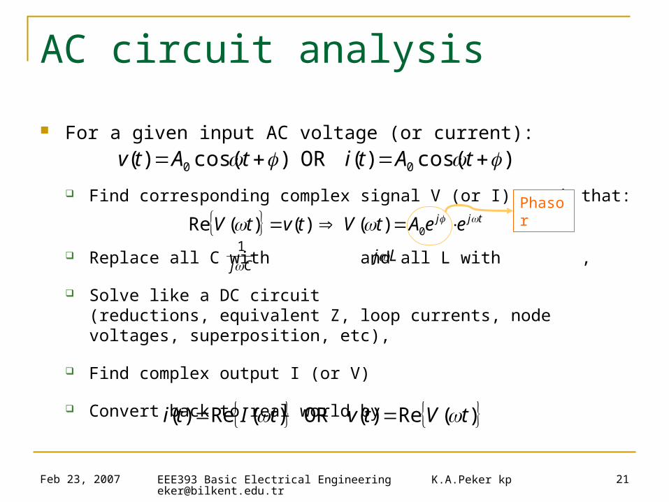
AC circuit analysis
For a given input AC voltage (or current):
Find corresponding complex signal V (or I), such that:
Replace all C with and all L with ,
Solve like a DC circuit (reductions, equivalent Z, loop currents, node voltages, superposition, etc),
Find complex output I (or V)
Convert back to real world by
)cos()( OR )cos()( 00 tAtitAtv
tjj eeAtVtvtV 0)( )()(Re
Cj1
Lj
)(Re)( OR )(Re)( tVtvtIti
Phasor
Feb 23, 2007 EEE393 Basic Electrical Engineering K.A.Peker [email protected]
22
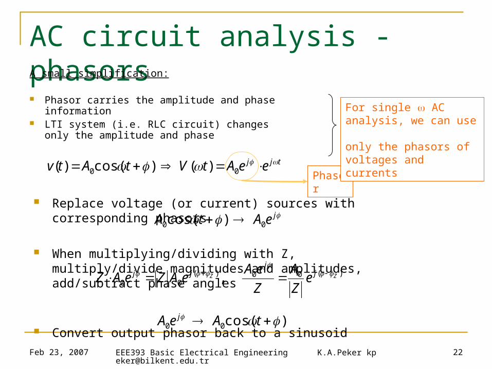
AC circuit analysis - phasorsA small simplification:
Phasor carries the amplitude and phase information LTI system (i.e. RLC circuit) changes
only the amplitude and phase
tjj eeAtVtAtv 00 )( )cos()(Phasor
For single AC analysis, we can use only the phasors of voltages and currents
Replace voltage (or current) sources with corresponding phasors
When multiplying/dividing with Z,multiply/divide magnitudes and amplitudes, add/subtract phase angles
Convert output phasor back to a sinusoid
jeAtA 00 )cos(
)cos( 00 tAeA j
)(00)(00 , ZZ j
jjj e
Z
A
Z
eAeAZeAZ

Feb 23, 2007 EEE393 Basic Electrical Engineering K.A.Peker [email protected]
23
Simple AC circuits
Series RC:
Series RL:
+v(t)
Ri(t)
C v
RCj
Rv
CjRZ
vi
CjRZ
11
11
1
1
Cj1
+v(t)
Ri(t)
L Lj v
RL
j
Rv
LjRZ
vi
LjRZ
1
11
Transfer Function
Feb 23, 2007 EEE393 Basic Electrical Engineering K.A.Peker [email protected]
24
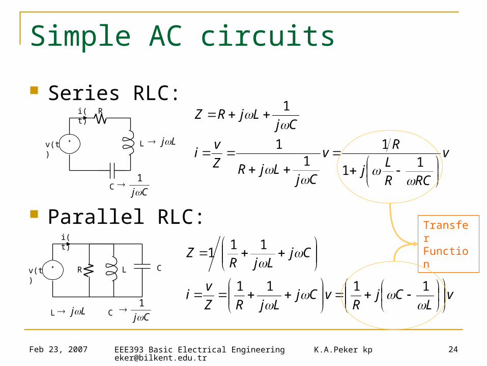
Simple AC circuits
Series RLC:
Parallel RLC:
+v(t)
R
L
i(t)
CCj
1
Ljv
RCRL
j
Rv
CjLjRZ
vi
CjLjRZ
11
11
1
1
+v(t) R L
i(t)
C Cj1
Lj
C
L
vL
CjR
vCjLjRZ
vi
CjLjR
Z
1111
111
Transfer Function


