WAM Client: FEDERAL ELECTRICITY AND WATER AUTHORITY (FEWA) Project: STANDARD SPECIFICATIONS FOR WATER WORKS Engineer WATER DIRECTORATE - ASSET MANAGEMENT DEPARTMENT Title: Technical Terms / Chapter 4/ Engineering Specifications / Pipeline Works Specifications. PS02-DI PIPES MATERIALS & INSTALLATION Office: DUBAI Order: Document: WMA_PRO_07/WAM-04-PS02 Rev: DEC/2014 2 SHEE T: 1 of: 61 Federal Electricity & Water Authority Water Directorate Asset Management Department STANDARD SPECIFICATIONS FOR WATER WORKS TECHNICAL TERMS Chapter – 4 Engineering Specifications E – Pipeline works Specifications PS 02 DI PIPES MATERIALS & INSTALLATION
Transcript
WAM
Client: FEDERAL ELECTRICITY AND WATER AUTHORITY (FEWA) Project: STANDARD SPECIFICATIONS FOR WATER WORKS
Engineer WATER DIRECTORATE - ASSET MANAGEMENT DEPARTMENT
A- SPECIFICATIONS FOR DUCTILE IRON PIPES, FITTINGS AND ACCESSORIES
1. SCOPE
This specification covers the general requirements for Ductile Iron (D.I.) pipes, fittings and accessories including material specifications, internal lining, external coating, joints, polyethylene sleeves etc. This specification sets the minimum acceptable requirements. In case of difference between this specification and the specified international standards then the most stringent requirements shall prevail.
2. APPLICABLE STANDARDS AND CODES
D.I. pipes, fittings and accessories including coating and polyethylene sleeve shall comply with the latest issue of the following standards and other relevant standards noted elsewhere in this specification:
ISO 62 Plastic – Determination of water absorption ISO 527 Plastics-Determination of tensile properties. ISO 887 Plain washers for metric bolts screws and nuts. ISO 974 Plastics-Determination of the brittleness temperature by impact. ISO 2230 Vulcanized rubber-guide to storage. ISO 2531- 2009 / ISO 2531- 1998 and EN 545 – 2010/ EN545- 2006 Ductile iron pipes, fittings, accessories and their joints for water or gas
applications. ISO 3506 Corrosion - resistant stainless steel fasteners. ISO 4014 Hexagon head bolts – Product grades A and B. ISO 4032 Hexagon nuts, style 1 – Product grades A and B. ISO 4179 Ductile iron pipes for pressure and non-pressure pipeline – Centrifugal
cement mortar lining – General requirements. ISO 4587 Adhesives – Determination of tensile lap-shear strength of rigid-to-rigid
bonded assemblies. ISO 4633 Rubber seals – Joint rings for water supply, drainage and sewerage
pipeline – Specification for materials. ISO 6600 Ductile iron pipes, centrifugal cement mortar lining – composition controls
of freshly applied mortar. ISO 6506-1 Metallic materials – Hardness testing – Brinell test – Part 1: Test method. ISO 6708 Pipe works components – Definition and selection of DN ISO 7005-2 Metallic flanges – Part 2: Cast iron flanges. ISO 7268 Pipe components – Definition of nominal pressure. ISO 7483 Dimensions of gaskets for use with flanges to ISO 7005. ISO 8179-1 Ductile iron pipes – External coating – Part 1: Metallic zinc with finishing
layer. ISO 8179-2 Ductile iron pipes – External coating – Part 2: Zinc rich paint with finishing
layer. ISO 8180 Ductile iron pipes – Polyethylene sleeving. ISO 8501-1 Preparation of Steel Substrates. ISO 10804 Restrained joint systems for ductile iron pipelines – Part 1: Design rules
and type testing. ISO 9001:2008 Quality Management System EN 1092-2 Circular flanges for pipes, valves, fittings and accessories, PN designated
– Part 2: Cast iron flanges.
WAM
Client: FEDERAL ELECTRICITY AND WATER AUTHORITY (FEWA) Project: STANDARD SPECIFICATIONS FOR WATER WORKS
Engineer WATER DIRECTORATE / ASSET MANAGEMENT DEPARTMENT
EN 14901 Epoxy coating of ductile iron pipes, fitting and accessories BS 2782 Methods of testing. Plastic. introduction BS 3416 Specification for bitumen - based coatings. BS 7079 Specification for surface finish of blast-cleaned steel for painting. BSEN 681 Elastomeric Seals BSEN 1563 Founding Spheroidal graphite Cast iron BSEN 10025 Hot rolled products of non-alloy Structural Steels BS EN 15167-1:2006 Ground granulated blast furnace slag for use in concrete, mortar and
grout. Definitions, specifications and conformity criteria EN 197-1:2011 Composition, specifications & conformity criteria for common cements DIN 30671 Thermo set plastics coatings for buried steel pipes DIN 30672 Coatings of corrosion protection tapes and heat Shrinkable material. DIN 4226 Aggregates for concrete. ASTM E 28 Standard test methods for softening point of resins derived from naval
stores by ring-and-ball apparatus
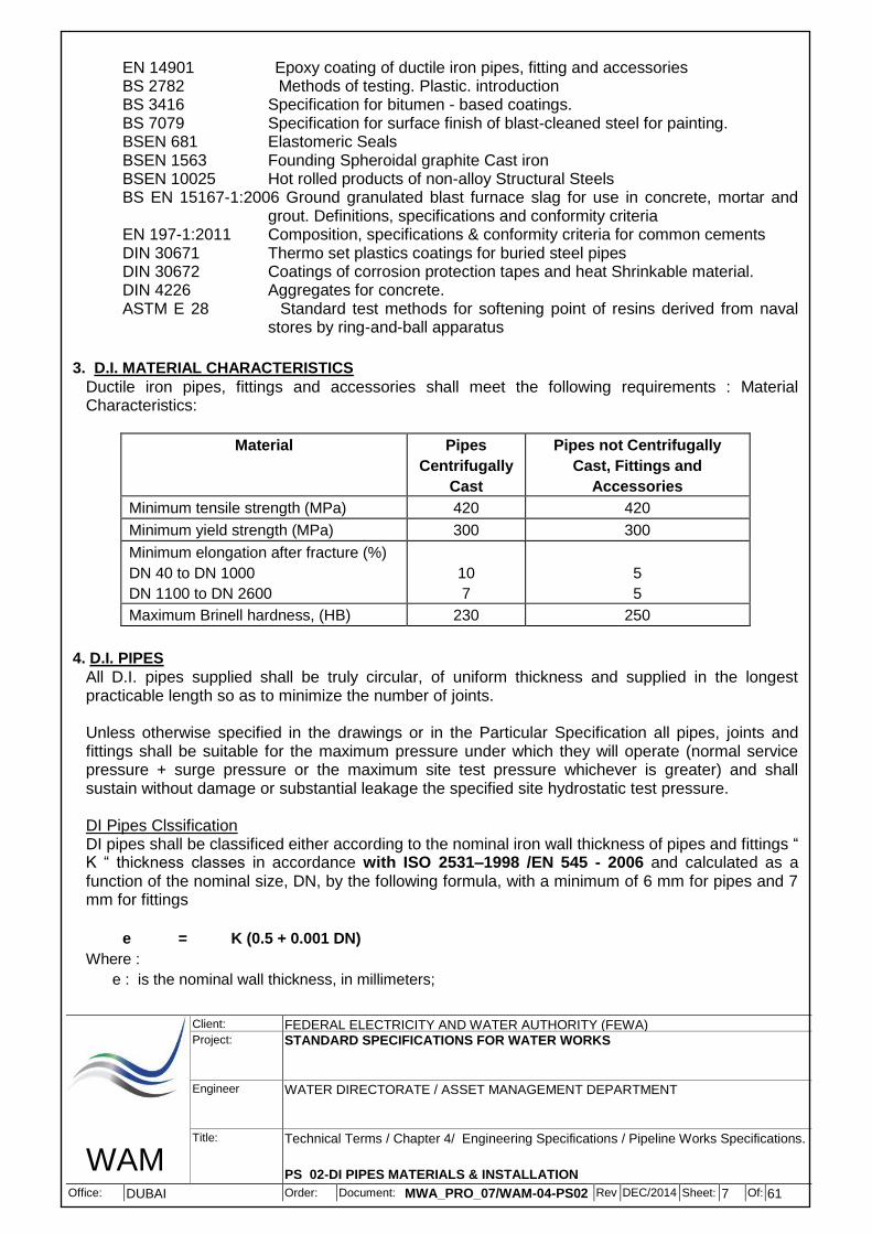
3. D.I. MATERIAL CHARACTERISTICS
Ductile iron pipes, fittings and accessories shall meet the following requirements : Material Characteristics:
Material Pipes
Centrifugally
Cast
Pipes not Centrifugally
Cast, Fittings and
Accessories
Minimum tensile strength (MPa) 420 420
Minimum yield strength (MPa) 300 300
Minimum elongation after fracture (%)
DN 40 to DN 1000
DN 1100 to DN 2600
10
7
5
5
Maximum Brinell hardness, (HB) 230 250
4. D.I. PIPES
All D.I. pipes supplied shall be truly circular, of uniform thickness and supplied in the longest practicable length so as to minimize the number of joints.
Unless otherwise specified in the drawings or in the Particular Specification all pipes, joints and fittings shall be suitable for the maximum pressure under which they will operate (normal service pressure + surge pressure or the maximum site test pressure whichever is greater) and shall sustain without damage or substantial leakage the specified site hydrostatic test pressure. DI Pipes Clssification DI pipes shall be classificed either according to the nominal iron wall thickness of pipes and fittings “ K “ thickness classes in accordance with ISO 2531–1998 /EN 545 - 2006 and calculated as a function of the nominal size, DN, by the following formula, with a minimum of 6 mm for pipes and 7 mm for fittings
e = K (0.5 + 0.001 DN)
Where :
e : is the nominal wall thickness, in millimeters;
WAM
Client: FEDERAL ELECTRICITY AND WATER AUTHORITY (FEWA) Project: STANDARD SPECIFICATIONS FOR WATER WORKS
Engineer WATER DIRECTORATE / ASSET MANAGEMENT DEPARTMENT
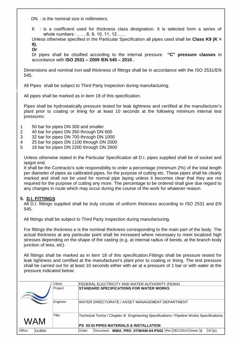
K : is a coefficient used for thickness class designation. It is selected form a series of whole numbers :…….8, 9, 10, 11, 12……
Unless otherwise specified in the Particular Specification all pipes used shall be Class K9 (K = 9). Or DI pipes shall be clssified according to the internal pressure “C” pressure classes in accordance with ISO 2531 – 2009 /EN 545 – 2010 .
Dimensions and nominal iron wall thickness of fittings shall be in accordance with the ISO 2531/EN 545.
All Pipes shall be subject to Third Party Inspection during manufacturing.
ENGINEERING\WATER\STANDARDS ENHANCEMENT All pipes shall be marked as in item 18 of this specification.
Pipes shall be hydrostatically pressure tested for leak tightness and certified at the manufacturer's plant prior to coating or lining for at least 10 seconds at the following minimum internal test pressures:
1 50 bar for pipes DN 300 and smaller 2 40 bar for pipes DN 350 through DN 600 3 32 bar for pipes DN 700 through DN 1000 4 25 bar for pipes DN 1100 through DN 2000 5 18 bar for pipes DN 2200 through DN 2600
Unless otherwise stated in the Particular Specification all D.I. pipes supplied shall be of socket and spigot end. It shall be the Contracto's sole responsibility to order a percentage (minimum 2%) of the total length per diameter of pipes as calibrated pipes, for the purpose of cutting etc. These pipes shall be clearly marked and shall not be used for normal pipe laying unless it becomes clear that they are not required for the purpose of cutting any more. The percentage to be ordered shall give due regard to any changes in route which may occur during the course of the work for whatever reason.
5. D.I. FITTINGS
All D.I. fittings supplied shall be truly circular of uniform thickness according to ISO 2531 and EN 545.
All fittings shall be subject to Third Party Inspection during manufacturing.
For fittings the thickness e is the nominal thickness corresponding to the main part of the body. The actual thickness at any particular point shall be increased where necessary to meet localized high stresses depending on the shape of the casting (e.g. at internal radius of bends, at the branch body junction of tees, etc).
All fittings shall be marked as in item 18 of this specification.Fittings shall be pressure tested for leak tightness and certified at the manufacturer's plant prior to coating or lining. The test pressure shall be carried out for at least 10 seconds either with air at a pressure of 1 bar or with water at the pressure indicated below:
WAM
Client: FEDERAL ELECTRICITY AND WATER AUTHORITY (FEWA) Project: STANDARD SPECIFICATIONS FOR WATER WORKS
Engineer WATER DIRECTORATE / ASSET MANAGEMENT DEPARTMENT
1 25 bar for fittings DN 300 and smaller (for fittings with PN 10 flanges test pressure shall
be 16 bar) 2 16 bar for fittings DN 350 through DN 600 3 10 bar for fittings DN 700 and larger
6. JOINTS 6.1 Flexible Joints
Flexible joints shall be of spigot and socket "push-on" type suitable for angular deflection in any direction and capable of axial movement to compensate for thermal expansion or contraction and ground movement. All flexible joints for D.I. pipes and fittings shall be designed in compliance with ISO 2531/ EN 545. Test certificate to be provided.
Joints may permit angular deflection to accommodate ground movements and to negotiate large radius bends. All joints shall be designed to be fully flexible. Consequently, the allowable angular deflection declared by the manufacturer shall not be less than (See BS 545):
1 3.5º for DN 40 to DN 300 2 2.5º for DN 350 to DN 600 3 1.5º for DN 700 to DN 2000
Allowable deflection with respect to Nominal Diameter DN shall be as per BS EN 545 latest edition.Rubber ring joints shall be of a type that will not deteriorate under local conditions either during storage or during operation. The rubber gasket shall be of EPDM elastomer or equivalent in accordance with ISO 4633 suitable for drinking water supply. Minimum fittings quantity supplied as spares shall be 2% of the B.O.Q.quantity.
Where mechanical type joints are specified, proposed and approved they shall be supplied complete with approved gaskets, glands, DI / stainless steel grade 316, nuts and all other necessary accessories. Where retainer glands are specified they shall be supplied with bolts and/or other necessary accessories.
6.2 Flanged Joints
Flange ended pipes and fittings shall only be used when connecting to valves or other special fittings as approved by FEWA/Engineer.
The flanges shall be raised faced and integrally cast or welded on. Screwed on flanges or glued on flanges are not acceptable. Rotatable flanges may be used for pipes and fittings up to DN 600.The dimensions and drilling of the flanges shall be to ISO 7005-2 / EN 1092-2. The pressure rating of the flanges shall be as given in the Data Sheet or Particular Specification. Flanged joints shall be supplied complete with gaskets, stainless steel grade 316 bolts, nuts and washers. Rubber gaskets shall be EPDM elastomer or equivalent approved in accordance with ISO 4633 suitable for drinking water supply. The gasket shall be minimum 3 mm thick and shall be metal reinforced for pressure rating of 16 bar and higher. The dimensions of the flange gaskets shall be to ISO 7483.
The nuts, bolts hexagonal headed, washers shall be of stainless steel grade 316. Nuts and bolts shall be suitable for the pressure rating specified in the Particular Specification. Nuts and bolts shall be to ISO 4014 and 4032 and washers to ISO 887.
WAM
Client: FEDERAL ELECTRICITY AND WATER AUTHORITY (FEWA) Project: STANDARD SPECIFICATIONS FOR WATER WORKS
Engineer WATER DIRECTORATE / ASSET MANAGEMENT DEPARTMENT
D.I. pipes and fittings with restrained coupling shall be utilized where pipelines have to cross roads through existing ducts or in areas with restricted accessibility where the use of concrete anchor blocks is prohibited, or as directed by FEWA/Engineer.The Contractor shall submit with his bid full details of the type of restrained coupling he proposes to use. Whenever in the course of work the Contractor intends to utilize restrained couplings he shall obtain prior approval from FEWA/Engineer.Calculation of the number of pipe lengths with restrained coupling required, shall follow the manufacturer's recommendation and shall be subject to FEWA/Engineer approval.
Restrained joints shall be designed to resist the axial thrust forces but maintaining flexibility and angular deflection. Restrained joints shall be designed in accordance with ISO 10804-1. The joint shall be capable of withstanding the greater of the test pressure or the service pressure + the surge pressure. The type of restrained joint shall be subject to FEWA/Engineer approval.The thrust resisting mechanism shall be separated from the sealing action of the gasket and shall not be in contact with potable water in the pipeline.
7. INTERNAL LINING TO D.I. PIPES AND FITTINGS 7.1 General
Unless otherwise specified in the Data Sheet or Particular Specification all D.I. pipes and fittings shall be internally lined with Sulphate resisting blast furnace slag cement mortar in accordance with the following specification and shall be certified as suitable for use with potable water by an internationally accepted organization such as UK's WRC (Water Research Centre). The cement mortar lining for D.I. pipes and fittings shall be in accordance with ISO 4179.The internal surface of the socket bell of all zinc/bitumen coated D.I. pipes and fittings shall be painted with a non-toxic solvent-free two part fusion bonded epoxy coating applied as referred in item 8.5 of this specification and to a minimum dry film thickness (DFT) of 300 microns or equivalent corrosion protection system to be approved by FEWA/Engineer. The thickness of the coating may be reduced only at the gasket locating ring to conform to manufacturer's recommended tolerances. All flange fittings shall be painted with a non-toxic solvent-free two part fusion bonded epoxy coating applied as referred in item 8.5 of this specification and to a minimum dry film thickness (DFT) of 300
7.2 Surface Preparation
Prior to cement lining application the inner surfaces of pipes and fittings shall be cleaned of dirt, loose rust particles, grease, oil or any other material which could be detrimental to good contact between the metal and the lining.
7.3 Cement
Cement to be used shall be of any cement type (OPC or SRC) complying with the requirements of EN 197-1:2011. The type of cement chosen by the CONTRACTOR shall be as per manufacturer's fabrication standards process.In our contract SRC type shall be used.
WAM
Client: FEDERAL ELECTRICITY AND WATER AUTHORITY (FEWA) Project: STANDARD SPECIFICATIONS FOR WATER WORKS
Engineer WATER DIRECTORATE / ASSET MANAGEMENT DEPARTMENT
7.4 Aggregates Only clean, rounded or crushed natural mineral materials aggregates shall be used in accordance with the requirement of the latest issue of the German DIN 4226 standards.
The distribution of grain sizes shall be:
a) the amount of particles passing through a standard sieve with an aperture size of 0.125
mm shall not be more than 10% by mass. b) the amount of particles with a diameter up to 1/3 of the normal lining thickness shall not
be less than 50% by mass. c) the maximum particle diameter shall not be greater than 1/2 of the normal lining
thickness. The amount of shall not exceed 5% by mass. 7.5 Additives
The use of cement additives is allowed, subject to FEWA/Engineer approval, provided that they do not adversely affect the quality of the lining, and that of the transported water.Additives shall not contain any elements which impart potable change in colour, taste or odor or present a health hazard. Certificates of non toxicity prepared and signed by recognized, independent laboratories, shall be made available to FEWA/Engineer.
7.6 Water
Water used for the mortar shall be of potable quality and shall not contain elements which influence the hardening of the lining or the quality of the water flowing through the finished pipes.
7.7 Mortar
Mortar for the lining shall be composed of cement, sand and water. The mortar shall be well mixed and of proper consistency to produce a dense homogenous lining that will adhere firmly to the DI pipe or fitting surface.
Weight of cement and sand shall be accurate to + 3%. The water/cement ratio shall not be more than 0.40.
The cement mortar shall not contain less than one part of cement to 3.5 parts of aggregates by weight as per ISO 4179.
7.8 Method of Lining
Lining application and quality for finished surface shall be in accordance with ISO 4179.
All pipes shall be lined by a centrifugal process. The consistency of the mortar and the time and speed of spinning the pipe shall be so adjusted to minimize the segregation of aggregates from the cement.
Fittings shall be lined by a spray method.In all cases a smooth finish of the lining shall be obtained, entirely free from cavities or visible air bubbles.The lining shall be uniform and extend from the spigot end up to the beginning of the socket cavity on the other side. The socket shall be left free of mortar.No seal coat shall be applied to the cement lining unless otherwise instructed and approved by FEWA/Engineer.
WAM
Client: FEDERAL ELECTRICITY AND WATER AUTHORITY (FEWA) Project: STANDARD SPECIFICATIONS FOR WATER WORKS
Engineer WATER DIRECTORATE / ASSET MANAGEMENT DEPARTMENT
7.9 Curing After application to pipes and fittings, the cement mortar shall be cured under controlled conditions (minimum 48 hours at more than 15ºC and 75% relative humidity).Alternative methods of curing are subject to approval of FEWA/Engineer.
7.10 Repair of Defective or Damaged Areas of Lining
Defective or damaged areas of lining may, at FEWA/Engineer's discretion, be patched by cutting out the defective or damaged lining to the metal so that the edges of the lining not removed are perpendicular or slightly undercut. The cut out area shall then be trawled with fresh mortar in the following composition :
1 One part cement (by weight). 2 One part sand. 3 Water of potable quality, with non toxic additive dispense of synthetic materials subject to
FEWA/Engineer's approval. 7.11 Thickness of the Lining
Thickness of the cement mortar lining shall be as follows:
Lining Thickness (mm)
Normal Minimum Mean Value
Minimum Value at One Point
80 – 600 5.0 4.5 3.5
700 – 1200 6.0 5.5 4.5
1400 – 2000 9.0 8.0 7.0
2200 – 2600 12.0 10.0 7.0
N.B.: The above figures differ from ISO 4179.
7.12 Mechanical Properties
The cement mortar lining shall have adequate resistance against compression and bending action. Representative test pieces shall have the following minimum properties after 28 days.
Water Cement Ratio of Test Piece
Compression Strength N/mm²
Bending Strength N/mm²
0.45 40 5.0
0.40 45 5.5
0.35 50 6.0
7.13 Quality of the Lining, Tests and Records
The lining shall be free from voids, ridges or corrugations that reduce the thickness of the lining to less than the specified minimum thickness. Lining shall have a smooth surface. There shall be no cavities or entrapped air, similarly there shall be no evidence of differences between portions of lining.
Linings shall be placed so that there is no gap between the pipe barrel and the lining.In some
circumstances thicker linings may be required and these shall be stated in the appropriate specification.
WAM
Client: FEDERAL ELECTRICITY AND WATER AUTHORITY (FEWA) Project: STANDARD SPECIFICATIONS FOR WATER WORKS
Engineer WATER DIRECTORATE / ASSET MANAGEMENT DEPARTMENT
If a lining is damaged it may be repaired on site using a one to one cement/sand mortar mix. (proportions by weight). Repairs shall cure for at least 72 hours. Mortar lining may show evidence of cracking, crazing or debonding after delivery to site. The following conditions may be accepted.
a) Cracking - provided that the longitudinal length of a crack is not more than 600 mm, width of
crack not more than 0.8 mm, circumferential cracks are not more than 50% of the circumference.
b) Crazing - provided that individual cracks are less than the limits given in (a), crazing over an area not exceeding 25% of the lining area may be acceptable.
c) Debonding - area of disbondment and radial displacement shall not exceed the values given in BSEN 545.
The following tests and measurements shall be conducted, recorded and filed with frequencies according to ISO 4179 and ISO 6600.
1 Determination of lining thickness. 2 Cross sectional sample. 3 Water cement ratio. 4 Aggregates. 5 Bonding and compression strength.
8. EXTERNAL COATING TO D.I. PIPES AND FITTINGS 8.1 General
Depending on the existing local conditions the external coating of D.I pipes and fittings shall be one of the following as given in the Data Sheets or Particular Specifications.
1. Metallic zinc with bituminous coating layer. (Standard coating for pipes)
2. Zinc rich paint with bituminous coating layer. (Standard coating for fittings)
All coatings are subject to the prior approval of FEWA/Engineer. Where non-toxic coating is specified, certification shall be required from an internationally recognized independent laboratory certifying that the material is safe for potable water service. At the discretion of FEWA/Engineer all special coatings on pipes and fittings shall be subjected to thickness checks and for holiday testing on Site in order to satisfy FEWA/Engineer that the coatings are within the specified limits and that no pin holes are present.The thickness of the coatings may be reduced only at the gasket locating ring to conform to manufacturer's recommended fitting tolerance.
8.2 Metallic Zinc with Bituminous Coating to D.I. Pipes
The system consists of a factory applied metallic zinc layer to ISO 8179-1 and a finishing layer of black bituminous coating of tropical standard to BS 3416 with a minimum dry film thickness (DFT) of 100 micron.The zinc content shall be minimum 99.99% and the mean mass of the zinc coating shall not be less than 200 g/m2 applied on the bare metal of the external surface of the pipe.
The external surface of the D.I. pipe spigot end at a minimum length of 250mm shall have non-toxic bituminous paint applied to a minimum DFT of 100 microns.
WAM
Client: FEDERAL ELECTRICITY AND WATER AUTHORITY (FEWA) Project: STANDARD SPECIFICATIONS FOR WATER WORKS
Engineer WATER DIRECTORATE / ASSET MANAGEMENT DEPARTMENT
The internal surface of the socket end shall be painted with a layer of zinc rich paint 150 g/m2 (zinc content not less than 85%) plus a layer of non-toxic bituminous paint to a minimum DFT of 100 microns and a total average DFT of 120 microns.
8.3 Zinc Rich Paint with Bituminous Coating to D.I. Fittings
The system consists of factory applied zinc rich paint layer to ISO 8179-2 and a finishing layer of black bituminous coating of tropical standard to BS 3416 with a minimum DFT of 100 micron.The thickness of the zinc rich coating shall be minimum 150 g/m2 and shall contain minimum 85% zinc in the dry film.
The external surface of the D.I. fitting spigot end at a minimum length of 250mm and the internal surface of the socket end, which may have direct contact with potable water, shall have a non-toxic bituminous paint applied to a minimum dry film thickness of 100 microns, and a total average DFT of 120 micron.
8.4 Polyurethane Coating 8.4.1 General
This section covers the factory application of solvent free polyurethane coating to D.I. pipes and fittings by airless, hot -spray techniques. The coating application shall conform with DIN 30671 or equivalent standard. For polyurethane coated D.I. pipes and fittings the external surface of the spigot end at a minimum length of 250mm and the internal surface of the socket end which may have direct contact with potable water shall have non-toxic solvent free two part epoxy coating applied to a minimum dry film thickness of 300 microns.
8.4.2 Materials
The coating shall be a high build, 100% solids urethane consisting of two components, one component based on polyurethane resin, which may or may not be modified with coal tar, and a second component based on an isocyanate resin.
The coating shall be capable of being airless sprayed to provide an average of 2.0 mm dry film thickness in a continuous application if an unmodified polyurethane is used or 2.5 mm dry film thickness if coal tar modified polyurethane is used. Whichever coating is used it shall meet all the requirements for mechanical properties as specified in DIN 30671.
The Contractor shall provide FEWA/Engineer with test certificates for the coating system to be employed. No materials shall be used unless FEWA/Engineer has accepted the results of the test specified.Notwithstanding the requirements of DIN 30671 the coating shall be guaranteed to preserve its integrity and maintain storage, handling, installation, testing and operation in the ambient conditions prevailing in the country of manufacture and in UAE. The test certificate shall state the properties of the coating and shall specify the test method used. The polyurethane coating system shall comply with the data included in Table 1 below:
WAM
Client: FEDERAL ELECTRICITY AND WATER AUTHORITY (FEWA) Project: STANDARD SPECIFICATIONS FOR WATER WORKS
Engineer WATER DIRECTORATE / ASSET MANAGEMENT DEPARTMENT
Polyurethane nominal thickness Polyurethane min. thickness
nominal thickness 2000 microns
minimum thickness 1500 microns
Coal tar modified polyurethane, nominal thickness Coal tar modified polyurethane, min. thickness
nominal thickness 2500 microns
minimum thickness 1800 microns
Holidays test (voltage) 10Kv
Impact Test 10 J (1 pipe per day)
Adhesion test Incision knife edge
(1 pipe per day)
8.4.3 Surface Preparation
All slag shall be removed and all sharp edges shall be ground down. Prior to blasting, all oil, grease, etc. shall be removed. All surfaces to be coated shall be blast cleaned to BS 7079 2nd quality or to ISO 8501-1. The photographic standard of surface preparation shall be to SIS 05 5900 Grade SA 2.5. The amplitude of surface roughness shall be 75+ 15 microns as measured using a surface profile gauge. In cases of dispute a sample plate shall be prepared and the profile shall be measured using a traveling microscope.
The Contractoer shall ensure that the type of abrasive used, its particle size and the blasting pressure used are suitable for achieving the required profile. The compressed air used in blasting shall be clean, dry and oil free.After blast cleaning all dust shall be removed by vacuum or a clean, oil free, dry air blast.
The application of the coating shall follow with the least possible delay.Any pipe not coated within 4 hours after blast cleaning shall be completely reblasted before coating. The surface to be coated shall be maintained at a temperature of at least 5º C above the dew point of the surrounding atmosphere at all times during the coating procedure.
8.4.4 Application
The polyurethane coating shall be applied using airless spray painting equipment strictly in accordance with the paint manufacturer's recommendations.
The paint shall be applied in a continuous process to achieve a covering film free from misses, tears, runs, sags, etc. and the minimum dry film thickness at any point as stated in Table 1 above.
All painted area shall be thoroughly dried before being overcoated and be free of all loose particles, dust, debris and atmospheric contamination.
The external surface of the D.I. pipe spigot end at a minimum length of 250mm and the internal surface of the socket end which may have direct contact with potable wall shall have non-toxic solvent free two part epoxy coating applied to a minimum dry film thickness of 300 microns.
WAM
Client: FEDERAL ELECTRICITY AND WATER AUTHORITY (FEWA) Project: STANDARD SPECIFICATIONS FOR WATER WORKS
Engineer WATER DIRECTORATE / ASSET MANAGEMENT DEPARTMENT
The pipe coating shall be completely continuous and free from all holidays, voids, pinholes or other defects. The thickness of the coating, the degree of adhesion to the pipe and the standard of workmanship generally shall be regularly checked in accordance with DIN 30671 and FEWA/Engineer's requirements.
Impact and adhesion tests shall be carried out on each day of production and the damage so caused shall be made good by the Contractor at his own cost.
The Contractor shall provide and operate an approved holiday detector with a loud alarm operating at the voltage specified. Holiday detection shall be carried out over 100% of surface area.The maximum number of holiday repairs allowed shall be six per nine meter length. The allowable number shall be reduced pro-rata for shorter pipe lengths. If, in the opinion of FEWA/Engineer holidays and other imperfections such as lifting edges, lack of adhesion, etc. are so frequent as to indicate poor application, the coating shall be stripped, the pipe cleaned and recoated at the Contractor's expense.
The pipe shall be repaired to pass the holiday detection test so that no holiday are present on the finally released coated pipe.
8.4.6 Repairs
In the event that problems are detected or repairs are needed, the Contractor shall take immediate steps to correct the situation.All repairs to the coated pipe shall be at the Contractor own expense. Scars, dents, damaged areas and holidays shall be cleaned by removing all rust, scale, dirt or foreign materials or loose coating using a small file. Repairs either in the factory or subsequently on site are to be made by means of a repair procedure approved by FEWA/Engineer prior to commencement of work.Any pipe subject to a coating repair procedure shall be fully re-examined in accordance with above inspection requirements.If cathodic protection is provided for the coated pipeline, coating at electrical connections shall be repaired according to the approved repair procedure.
8.4.7 Joint Protection
All joints of polyurethane ductile iron coating coated pipes shall be protected by heat shrinkable pipe sleeves or collars. The heat-shrinkable sleeves or collars shall have a high shrink ratio as well as high penetration resistant thick walled structure which together with an internally coated adhesive mastic sealant shall ensure a reliable vacuum-tight anti corrosion coating over the bare pipe joint and the polyurethane coated pipe ends. The heat-shrinkable sleeve shall be manufactured from a radiation cross linked, thermally stabilized, UV-resistant modified polyolefin sheet material with an inner surface of a controlled thickness visco-elastic sealant which shall be in accordance with the following minimal requirements :
WAM
Client: FEDERAL ELECTRICITY AND WATER AUTHORITY (FEWA) Project: STANDARD SPECIFICATIONS FOR WATER WORKS
Engineer WATER DIRECTORATE / ASSET MANAGEMENT DEPARTMENT
Water absorption ISO 62 23ºC, 24 hrs 0.1 % (max.) 0.05%
* CHS = cross head speed
Sealant Material
PROPERTY TEST METHOD
CONDITION REQUIREMENT
TYPICAL VALUE
Softening Point ASTM E28 85ºC (min.) 92ºC
Peel strength to steel, PE and epoxy
DIN 30672 23ºC, CHS* 100 mm/min
15N/cm (min.) 25 N/cm
Peel strength to steel After conditioning for 100 days at 50ºC
DIN 30672 23ºC, CHS* 100 mm/min
12N/cm (min.) 25 N/cm
Shear strength
ISO 4587 23ºC, 1 mm thickness
CHS*50 mm/min
10N/cm²(min) 15N/cm²
*CHS = cross head speed Dimensions
Backing thickness as supplied : 0.9 mm nominal Sealant thickness as supplied : 1.5 mm nominal Sleeve width as supplied : 300, 450 or 600 mm nominal. 8.5 Fusion Bonded Epoxy Coating
The system consist of factory applied fusion bonded powder epoxy coating externally and internally. The minimum dry film thickness of the coating shall be 300 microns.The powder epoxy resin shall be applied by electrostatic spray and shall be non toxic suitable for use in contact with drinking water. The powder material and method of application shall be subject to FEWA/Engineer approval.
The D.I. pipe or fitting shall be blast cleaned to SIS 05 5900 Grade SA 2.5 Rust, grease and other foreign maters shall be removed prior to coating application as per ISO 8501-1.
The temperature of the metal shall be adjusted to ensure complete polymerisation of the powder material.After coating application the coating shall be allowed to cure before being cooled with water to permit handling and inspection.
WAM
Client: FEDERAL ELECTRICITY AND WATER AUTHORITY (FEWA) Project: STANDARD SPECIFICATIONS FOR WATER WORKS
Engineer WATER DIRECTORATE / ASSET MANAGEMENT DEPARTMENT
The coating shall be free from blisters, pinholes, runs, sags or any other irregularities and shall have uniform color, gloss and thickness. The coating shall be free from holidays. Every D.I. pipe or fitting shall be inspected for holidays over 100% of its coated surface. The holiday detector shall be set at 2.2 kV with a rate of travel of the probe over the surface shall not exceed 300 mm/s.The minimum impact resistance of the coating when tested in accordance with ASTM G14 shall be 18J without causing holidays.
The coating shall not show any tendency for disbondment or blistering. Cathodic disbondment test shall be carried out in accordance with ASTM G42. The maximum coating disbondment shall be 5mm radius from the edge of the artificial holiday.
9. FLANGE ADAPTORS
Flange adapters shall be installed as shown on the drawings to facilitate removal of valves and other items for servicing/replacement. The material of the body end ring and sleeve shall be ductile iron grade 420/12 to BSEN 1563 or steel grade S275 to BSEN 10025 as approved by FEWA/Engineer. The studs, nuts, bolts shall be stainless steel grade 316 for flange connection between adaptor to piping or equipment. The gasket shall be EPDM to ISO 4633 or BSEN 681-1 suitable for drinking water.
The flange pressure rating shall be as given in the Data Sheet or Particular Specification. The coating shall be factory applied non toxic fusion bonded epoxy powder with min dry film thickness of 300 microns.
10. STEPPED COUPLINGS
Stepped couplings shall be used to connect the spigot ends of two pipes of different nominal diameters.The material of the body ring and sleeve shall be ductile iron grade 420/12 to BSEN 1563 or steel grade S275 to BSEN 10025. The nuts, bolts and washers shall be stainless steel 316 for flange connection between coupling to piping or equipment . The gaskets shall be EPDM to ISO 4633 or BSEN 681-1 suitable for drinking water. The coating shall be factory applied non toxic fusion bonded epoxy powder with min dry film thickness of 300 microns.
11. DISMANTLING JOINTS
Dismantling joints shall be installed as shown on the drawings to facilitate removal of valves and other equipment for servicing/replacement. The dismantling joints shall be of the tied/restrained type.
The material of the body, ring and sleeve shall be ductile iron grade 420/12 to BSEN 1563 or steel grade S275 to BSEN 10025 as approved by FEWA/Engineer. The nuts, bolts, studs, tie rods, washer shall be stainless steel 316 for flange connection between dismantling joint to piping or equipment. The gaskets shall be EPDM to ISO 4633 or BSEN 681-1 suitable for drinking water.
WAM
Client: FEDERAL ELECTRICITY AND WATER AUTHORITY (FEWA) Project: STANDARD SPECIFICATIONS FOR WATER WORKS
Engineer WATER DIRECTORATE / ASSET MANAGEMENT DEPARTMENT
The pressure rating of the flanges shall be as given in the Particular Specification. The coating shall be factory applied non toxic fusion boded epoxy powder or Rilsan Nylon II with normal dry film thickness of 300 microns and minimum DFT of 250 microns.
12. SPLIT TEES FOR UNDER PRESSURE CONNECTIONS
Split tees shall be ductile iron grade 420/12 to BSEN 1563. The sealing mechanism shall be by rubber ring set in a locating groove around the branch opening and held firmly against the mainline pipe by the pressure of the opposite bolted half or alternatively by full length rubber gaskets along the mating halves and at the separate end flanges. The rubber gaskets shall be EPDM to ISO 4633 or BSEN 681-1 suitable for drinking water. The bolts, nuts, washers shall be stainless steel 316. The split tees shall be coated with non toxic fusion bonded epoxy powder with min dry film thickness of 300 microns.
13. DUCTILE CAST IRON COLLAR
DI. Collar shall be movable on the Pipe barrel (slide type) with mechanical joint on both sides. 14. PUDDLE FLANGES OR SEALING FLANGES
Puddle flanges or sealing flanges shall be used in all situation where a ductile iron pipe is cast into a chamber wall where restraint is not required. The sealing should be water tight between the pipe and the opening through which it will pass. If the seal is made of two parts jointed by nuts and bolts they should be galvanized.
15. THRUST / ANCHOR FLANGES
Thrust/anchor flanges shall be used where D.I. pipes or fittings are cast into the chamber wall and shall be designed to restrain the connecting valves or other equipment installed inside the chamber.Thrust/anchor flanges shall be integrally cast or factory welded on to the pipe piece as approved by FEWA/Engineer. Bolted or screwed on thrust flanges shall are not acceptable. The coating to the thrust/anchor flange shall be similar to that of the pipe/fitting. The position of the thrust/anchor flange shall be as shown on the drawings or determined on site.
16. POLYETHYLENE SLEEVES
Protective polyethylene sleeves shall be used with all D.I. pipes and fittings to be installed in buried condition and shall be in accordance with ISO 8180. The polyethylene sleeve manufacturer shall have the ISO 9001/2000 quality control certificate.
The polyethylene sleeve shall be black, resistant to the effect of ultra violet light, tubular film in accordance with the latest issue of ASTM D-1248 or approved equivalent standard. The minimum nominal thickness of the sleeve shall be 0.010 inch (250 microns) with a maximum minus tolerance of 10%.
The material shall be made from a polymer with a melt flow index as measured according to BS 2782, of 10 or less and a density in the range of 0.915 to 0.925 g/ml. The sleeve shall be free from pinholes, gels, undispersed raw materials and particles of foreign matter. The film may not contain more than 5% by weight of material other than polyethylene.
WAM
Client: FEDERAL ELECTRICITY AND WATER AUTHORITY (FEWA) Project: STANDARD SPECIFICATIONS FOR WATER WORKS
Engineer WATER DIRECTORATE / ASSET MANAGEMENT DEPARTMENT
Polyethylene sleeving shall be stored in cool dry store away form direct sunlight or excessive heat. Rolls shall be supplied individually packed in black polyethylene sacks and clearly labeled with the date of manufacture, the length of the roll, the pipe size for which it is intended, the name of the manufacturer and the country of manufacture. The stock of the polyethylene sleeve shall be rotated on the first in/first out basis.
17. VENDOR DOCUMENTATION
The Contractor shall furnish the following vendor data as a minimum, with his bid:
- Pre-qualification documents of the proposed manufacturer. - Quality Management system Certificate - Type Tests Certificate for Pipes, Fittings & gaskets. - If fittings are supplied separately from pipes, full “Third Party Type Tests Certificate” and
their compatibility with the pipes shall be made available by supplier to FEWA. - Compliance Statement - Technical Data Sheet - Non Toxicity Certificate for pipes & fittings material, lining, gasket, epoxy coating - Dimensional details of pipes and fittings. - Detailed material specifications. - Local (UAE) agent name and address. - Any other Certificate required as per Standard - Reference list showing experience details of supply & installation for minimum three years
of performance history in Government utilities in UAE/GCC Countries for different diameters.
Bids not accompanied by any of above-mentioned information/data shall be considered incomplete, and liable to be rejected.
18. MARKING All items shall bear the following distinct marks :
- Number of standard - Manufacturer's identification mark - Indication that the item is made of ductile iron - Nominal diameter - Class of pipes and flanges - Year of manufacture - Home line positions at pipe ends - Client’s name, i.e. “FEWA” - Contract No. - Batch No.
19. TRANSPORTATION OF PIPES
DI pipes and fittings shall be properly and securely transported from the place of manufacture to the site/ stores. No nesting of DI pipe shall be allowed at any time during the transport.Where pipes are transported by truck, the pipes shall be transported on wooden cradles or skids and shall be properly protected from contact with metal surfaces by rubber or wooden spacers or wedges.
WAM
Client: FEDERAL ELECTRICITY AND WATER AUTHORITY (FEWA) Project: STANDARD SPECIFICATIONS FOR WATER WORKS
Engineer WATER DIRECTORATE / ASSET MANAGEMENT DEPARTMENT
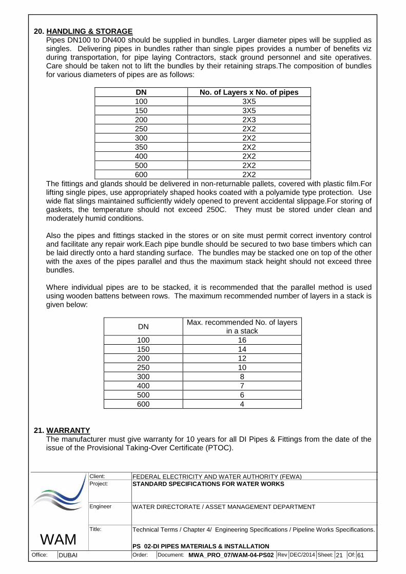
20. HANDLING & STORAGE Pipes DN100 to DN400 should be supplied in bundles. Larger diameter pipes will be supplied as singles. Delivering pipes in bundles rather than single pipes provides a number of benefits viz during transportation, for pipe laying Contractors, stack ground personnel and site operatives. Care should be taken not to lift the bundles by their retaining straps.The composition of bundles for various diameters of pipes are as follows:
DN No. of Layers x No. of pipes
100 3X5
150 3X5
200 2X3
250 2X2
300 2X2
350 2X2
400 2X2
500 2X2
600 2X2
The fittings and glands should be delivered in non-returnable pallets, covered with plastic film.For lifting single pipes, use appropriately shaped hooks coated with a polyamide type protection. Use wide flat slings maintained sufficiently widely opened to prevent accidental slippage.For storing of gaskets, the temperature should not exceed 250C. They must be stored under clean and moderately humid conditions. Also the pipes and fittings stacked in the stores or on site must permit correct inventory control and facilitate any repair work.Each pipe bundle should be secured to two base timbers which can be laid directly onto a hard standing surface. The bundles may be stacked one on top of the other with the axes of the pipes parallel and thus the maximum stack height should not exceed three bundles. Where individual pipes are to be stacked, it is recommended that the parallel method is used using wooden battens between rows. The maximum recommended number of layers in a stack is given below:
DN Max. recommended No. of layers
in a stack
100 16
150 14
200 12
250 10
300 8
400 7
500 6
600 4
21. WARRANTY
The manufacturer must give warranty for 10 years for all DI Pipes & Fittings from the date of the issue of the Provisional Taking-Over Certificate (PTOC).
WAM
Client: FEDERAL ELECTRICITY AND WATER AUTHORITY (FEWA) Project: STANDARD SPECIFICATIONS FOR WATER WORKS
Engineer WATER DIRECTORATE / ASSET MANAGEMENT DEPARTMENT
B - SPECIFICATIONS FOR DI PIPELINE INSTALLATION WORKS 1. SCOPE OF SPECIFICATIONS
This specification covers the construction, installation and testing of Ductile Iron (D.I.) pipes and fittings including route survey, excavation, backfilling, pipe wrapping, laying, protection, etc.
2. APPLICABLE STANDARDS AND CODES
Unless otherwise specified the works shall conform to the following standards and other standards noted elsewhere in this specification.
BS 8010 : Part 1 Pipelines on land : general
BS 8010 : Part 2.1 Pipelines on land : design, construction and installation
AWWA C651 Disinfecting water mains
3.PIPELINE ROUTE SURVEY
The Contractor shall be responsible for all the necessary surveying and pegging out of the pipeline route, tank site, storage area(s), camp area(s) etc. Deviations from the proposed route shown on the tender drawings due to the local site condition shall require the approval of the FEWA in writing. The final route and alignment shall, however, be approved by the concerned roads authority and other related authorities.
The Contractor shall prepare trial pits at each kilometer to know the soil conditions and for
requirement of sand bedding or filling and water table level for requirement of dewatering and submit report to FEWA for approval before submitting the profiles.
The Contractor shall prepare and submit to the FEWA, all necessary survey drawings including
longitudinal profiles for approval and record.
The survey work shall be deemed to be complete on receipt of the FEWA's written approval and upon acceptance of the work, the Contractor however shall be obliged to maintain the pegs in an acceptable condition and at their respective locations, for as long as may be considered necessary for the construction works.
Before commencement of excavation for pipe trench, the CONTRACTOR shall carryout full route
survey and preparation of pipeline profile drawings, all in accordance with the construction programme, subject to FEWA's approval. All survey work shall be referred to the National Grid, Universal Traverse Mercator (UTM).
The survey shall be carried out using calibrated survey equipment approved by FEWA. The survey
work shall be executed by qualified land surveyor approved by FEWA.
The Contractor shall set out the route of the pipeline in accordance with the drawings. The route shall be marked by 75x75x1000mm wooden poles set in to the ground in a concrete surround. The poles shall be set along centre line of the pipeline at intervals of 50m chainage, at every bend, air valve, washout or valve chamber and at all physical obstructions (existing chambers, excavations, etc.).The chainage of the pipeline shall be marked on every pole. All poles shall be painted as follows: -
WAM
Client: FEDERAL ELECTRICITY AND WATER AUTHORITY (FEWA) Project: STANDARD SPECIFICATIONS FOR WATER WORKS
Engineer WATER DIRECTORATE / ASSET MANAGEMENT DEPARTMENT
Red - Centreline of pipe or pair of pipes Red with White stripe - Horizontal bend, washout or valve chamber, etc. White marker - Outer limits of the working width Yellow marker - Other Service
From the results of this survey, the Contractor shall prepare the pipeline alignment and profile drawings. Pipeline profile drawings shall be presented at a horizontal scale of 1:000 and a vertical scale of 1:100 or as directed by FEWA/Engineer. All drawings shall be submitted to the FEWA for approval on ISO size A1 paper prints or any suitable size.
The Contractor shall plot on these drawings the detailed routes and profiles of the pipelines. The
profile shall comply with the requirements of pipeline minimum cover, minimum gradient and spacing of air valves, washout and valve chambers and the location of the marker posts. The distance between marker posts from any bend (Change of Direction on) of the pipeline to the next post of the straight runs, and all post/s thereafter shall be at 200 Meters interval. The distance between the last post of the straight run and the next bend shall be as per FEWA/Engineer’s approval. As required FEWA reserves the right to change the distances of marker post/s between bends to compensate for any distance less than 200 M. The route profile shall be plotted under the relevant section of the pipeline route plan. The route plan shall show a strip of land 20m wide, centered on the pipeline route, including the adjacent asphalt road if any.
The profiles shall also show the chainage of the pipeline at the points of ground level
measurements and at any change in profile. The Contractor shall determine the invert level of the pipeline at the points of level measurement and mark these levels on the drawings. The diameter and details of the pipeline shall also be shown.
FEWA shall approve or otherwise amend the route or profile of the pipelines and the Contractor
shall revise the drawings accordingly. The revised approved drawings shall be marked "APPROVED" and thereafter shall become the Contract Drawings for the pipeline construction. These drawings may also then be used by the Contractor for finalizing the pipeline materials order.
The survey shall include information on all the existing services and facilities such as roads, power
lines and cables, sewers, treated effluent pipelines, irrigation pipelines, water pipelines, oil/gas pipelines, drainage channels and culverts, and plantations, within a 20m wide strip centered on the pipeline route.
The existing underground utilities traversing the pipeline route shall be exposed by hand excavation
and their exact lines and levels shall be included in the results of the survey. The Contractor shall record by site investigation the exact lines and levels of the pipelines that are to be connected to the proposed pipeline. The results of the survey shall be presented in soft and hard copies to FEWA.
4. EXCAVATION OF TRENCHES AND PITS 4.1 General
The lines of trenches for all pipelines are to be carefully set out to the alignment of the pipelines.Excavation for trenches shall be carried out for a maximum of four pipe lengths in advance of the pipe laying or as determined by the FEWA. The trenches shall be excavated to the required line and level as shown on the drawings or as approved by FEWA, and shall, at all times, be drained & dried and braced to ensure safe and efficient pipe laying. In locations where services, or other structures are near the pipeline route, only hand excavation will be permitted.
WAM
Client: FEDERAL ELECTRICITY AND WATER AUTHORITY (FEWA) Project: STANDARD SPECIFICATIONS FOR WATER WORKS
Engineer WATER DIRECTORATE / ASSET MANAGEMENT DEPARTMENT
All rubbish, filth and matter of an offensive nature taken out of any excavation shall be disposed of at once and not left on the surface.
The pipeline laid around and about Head works, well fields, Tanks, existing services, Pumping
stations and other similar works, shall be laid at such depths as are required to suit the works to which they are intended to be connected, or to avoid interference with the existing services and installations.
The rate for excavation given in "Schedule of Quantities and Rates" is for making the trenches in all
types of soils (soft, medium, hard solid rock, paved or asphalt etc.) and in all types of locations/circumstances including making the formation level even and service track and to the depth as mentioned in Article 4.5 including shoring, strutting, dewatering, leveling etc.
The Contractor shall also cut and fill the ground as required necessary, which includes making a
service track, duly compacted, along the pipeline route, to make the ground formation even, to facilitate the laying, inspection, as well as for FEWA’s maintenance. The service track shall be properly maintained by periodic watering, grading and leveling etc. as required, throughout the period of contract. The payment for cutting and filling shall be according to the relevant Item of the B.O.Q.
The Contractor must estimate for himself the proper price for completing the whole job irrespective
of difficulties met in excavations. The Tenderer in his price for relevant item/items shall include cost on account of this article as given in the `Schedule of Quantities & Rates'. No additional payment shall be made for the cost on account of this article.
4.2 Setting Out
The lines of trenches for all pipelines are to be carefully set out to the alignment of the pipelines. The Contractor shall be entirely responsible for accurately setting out the WORKS. The levels shall be relative to the ACD levels as mentioned in the contract administration requirements. Before commencing any work the Contractor shall give such notice to the FEWA to enable FEWA to check the setting out, and in any event not less than 48 hours notice. No approval either given or implied by the FEWA shall relieve the Contractor of his obligations in connection with the setting out.
The Contractor shall set out the Works in accordance with the drawings or as otherwise instructed by the FEWA. Should the Contractor wish to alter the line, level or any other part of the WORKS, the prior written approval of the FEWA must be obtained.
4.3 Grading of Pipeline Route
The Contractor shall cut and fill the ground, including supply of imported material and carting off surplus earthworks, as required necessary which includes making a service track along the pipeline route to make the ground formation level even, for his own convenience as well as for FEWA’s inspection and maintenance. It shall be made in such a way that FEWA representative can inspect the route in a normal car. No extra payment shall be made for all such types of works.
The Contractor also has to grade the pipeline route, as required, and he is responsible for necessary cutting and filling in any type of soil. The payment for such cutting and filling works shall be according to the relevant item of schedule of quantities and rates.
WAM
Client: FEDERAL ELECTRICITY AND WATER AUTHORITY (FEWA) Project: STANDARD SPECIFICATIONS FOR WATER WORKS
Engineer WATER DIRECTORATE / ASSET MANAGEMENT DEPARTMENT
The Contractor shall provide and maintain suitable temporary crossings over pipe trenches at those positions where the excavation of a pipe trench prevents the normal movements of traffic. To permit the passage of pedestrian, vehicular and other traffic the Contractor shall phase the excavation, pipe laying, jointing and reinstatement in such a way as to provide reasonable access to houses, roads, footpaths, etc. The Contractor shall remove the whole of the turf, topsoil, concrete, flagging, paving, kerbing, road metalling and other materials from the site of any excavation and preserve the same for re-use afterwards. The ground shall be excavated for the permanent and temporary works to the required depth, widths and levels so that the dimensions of the permanent work shall not be less than is shown on the drawings, or as may be directed.
4.5 Trench Depth
The depth of cover shall be kept 900 mm. for pipe of up to 300 mm. dia. and 1100 mm for pipes above 300 mm. and up to 600 mm diameter. and 1500 mm for pipes above 600 mm diameter or as shown on the drawing, measured from the surrounding or finished surface level except where the pipe may be lifted or lowered when crossing other services as instructed by the FEWA.
In special cases, for example where the sub-soil is heavily impregnated with corrosive substances, pipelines may occasionally have to be laid on the surface, if traffic and other conditions permit. In such cases the pipes shall be supported on dwarf blocks of cement concrete, as per the FEWA's approval at intervals not exceeding 3000 mm.
Where trenches are required to be deeper than the general depth mentioned above, the Contractor shall dig the trench to the required depth with a gradual slope necessary for the proper laying of the pipeline. Pipelines shall not be laid closer than 600mm to other pipelines, services or structures or as directed by the FEWA.
The trenches shall be carefully trimmed on sides and bottom so that pipelines, when laid shall rest on the sand bed (as described hereafter) of the trench through their full lengths and shallow joint holes being left for the joints where necessary.
4.6 Trench Width
The trench width is dependent on the nature of the ground, depth, and pipe size. The clear width of the trench at any level shall be minimum of one pipe outside diameter, plus 300mm clearance on either side. In all cases the trench shall be excavated sufficiently wide to ensure efficient laying and jointing of the pipes.
WAM
Client: FEDERAL ELECTRICITY AND WATER AUTHORITY (FEWA) Project: STANDARD SPECIFICATIONS FOR WATER WORKS
Engineer WATER DIRECTORATE / ASSET MANAGEMENT DEPARTMENT
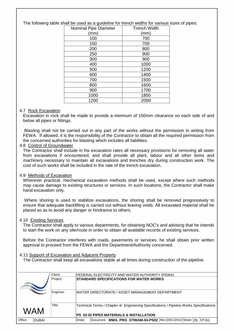
The following table shall be used as a guideline for trench widths for various sizes of pipes:
Nominal Pipe Diameter (mm)
Trench Width (mm)
100 700
150 700
200 800
250 900
300 900
400 1000
500 1200
600 1400
700 1500
800 1600
900 1700
1000 1800
1200 2000
4.7 Rock Excavation
Excavation in rock shall be made to provide a minimum of 150mm clearance on each side of and below all pipes or fittings.
Blasting shall not be carried out in any part of the works without the permission in writing from FEWA. If allowed, it is the responsibility of the Contractor to obtain all the required permission from the concerned authorities for blasting which includes all liabilities.
4.8 Control of Groundwater The Contractor shall include in his excavation rates all necessary provisions for removing all water from excavations if encountered, and shall provide all plant, labour and all other items and machinery necessary to maintain all excavations and trenches dry during construction work. The cost of such works shall be included in the rate of the trench excavation.
4.9 Methods of Excavation
Wherever practical, mechanical excavation methods shall be used, except where such methods may cause damage to existing structures or services. In such locations, the Contractor shall make hand excavation only.
Where shoring is used to stabilize excavations, the shoring shall be removed progressively to ensure that adequate backfilling is carried out without leaving voids. All excavated material shall be placed so as to avoid any danger or hindrance to others.
4.10 Existing Services
The Contractor shall apply to various departments, for obtaining NOC's and advising that he intends to start the work on any site/route in order to obtain all available records of existing services.
Before the Contractor interferes with roads, pavements or services, he shall obtain prior written approval to proceed from the FEWA and the Department/Authority concerned.
4.11 Support of Excavation and Adjacent Property
The Contractor shall keep all excavations stable at all times during construction of the pipeline.
WAM
Client: FEDERAL ELECTRICITY AND WATER AUTHORITY (FEWA) Project: STANDARD SPECIFICATIONS FOR WATER WORKS
Engineer WATER DIRECTORATE / ASSET MANAGEMENT DEPARTMENT
The Tendered cost of the project shall be inclusive of all works required for shoring up of the buildings along or near the trench which are likely to be endangered by the execution of the work.
When excavating in unstable soils or where the excavations are necessarily deep, the Contractor shall submit to the FEWA his detailed proposals for supporting the excavations at the site at least seven days prior to commencement of any excavation work. His proposal shall take into account the nature of the ground to be excavated, the water table level at the site and the closeness of adjacent buildings and roads.
If, in the opinion of the FEWA the support proposed by the Contractor is insufficient, then the FEWA will order the provision of stronger or alternative support for the excavations than that proposed by the Contractor. In this event the Contractor shall adopt the same at no extra cost to the FEWA. The Contractor shall not remove any temporary works supporting the excavation until in the opinion of the FEWA, the permanent work is sufficiently advanced to permit such removal. This shall then be executed under the personal supervision of a competent foreman. The cost on account of this article shall be included by the Tenderer in his price for the relevant item/items as given in the "Schedule of Quantities and Rates". No additional payment therefore shall be made for the cost on account of this article.
4.12 Surplus Excavated Material
All surplus excavated material, or material unsuitable for D.I. pipeline backfilling, arising from any part of the trench excavation, shall be removed from the site and disposed off by the Contractor at location as allocated by the local concerned authority at his own cost.
5. D.I. PIPE HANDLING AND LAYING
In general D.I. pipes shall be handled and laid according to an approved standard. 5.1Stretch Of Restrained Pipes Around Fitting
A.) For restrained pipes, a weld bead on the pipe spigot is required, which can be done by electric welding unit, as per manufacturer's recommendation.
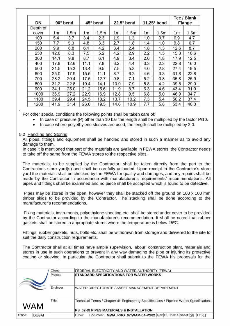
Also for restrained pipes the following is the schedule of the length (stretches) of restrained pipes, on either side of the fitting (bend/Tee/blank flange) under the following soil conditions:
Soil is gravel, silty sand or clay.
Internal angle of friction of soil = 30 degree
Resistance = 0.6da N/cm2
Density = 2 t/m3
No water table is present
Pipe coated with zinc & bituminous paint
Safety coefficient = 1.2
Test pressure = 10 bar
Note: The following table indicates that the lengths mentioned are minimum, and the Contractor has to design and follow manufacturer's recommendations.
WAM
Client: FEDERAL ELECTRICITY AND WATER AUTHORITY (FEWA) Project: STANDARD SPECIFICATIONS FOR WATER WORKS
Engineer WATER DIRECTORATE / ASSET MANAGEMENT DEPARTMENT
. For other special conditions the following points shall be taken care of:
In case of pressure (P) other than 10 bar the length shall be multiplied by the factor P/10.
In case where polyethylene sleeves are used, the length shall be multiplied by 2.0.
5.2 Handling and Storing All pipes, fittings and equipment shall be handled and stored in such a manner as to avoid any damage to them. In case it is mentioned that part of the materials are available in FEWA stores, the Contractor needs to take off the same from the FEWA stores to the respective sites. The materials, to be supplied by the Contractor, shall be taken directly from the port to the Contractor’s store yard(s) and shall be carefully unloaded. Upon receipt in the Contractor’s store yard the materials shall be checked by the FEWA for quality and damages, and any repairs shall be made by the Contractor in accordance with manufacturer’s requirements/ recommendations. All pipes and fittings shall be examined and no piece shall be accepted which is found to be defective. Pipes may be stored in the open, however they shall be stacked off the ground on 100 x 100 mm timber skids to be provided by the Contractor. The stacking shall be done according to the manufacturer's recommendations. Fixing materials, instruments, polyethylene sheeting etc. shall be stored under cover to be provided by the Contractor according to the manufacturer's recommendation. It shall be noted that rubber gaskets shall be stored in appropriate stores where the temperature is below 25ºC. Fittings, rubber gaskets, nuts, bolts etc. shall be withdrawn from storage and delivered to the site to suit the daily construction requirements.
The Contractor shall at all times have ample supervision, labour, construction plant, materials and stores in use in such operations to prevent in any way damaging the pipe or injuring its protective coating or sleeving. In particular the Contractor shall submit to the FEWA his proposals for the
WAM
Client: FEDERAL ELECTRICITY AND WATER AUTHORITY (FEWA) Project: STANDARD SPECIFICATIONS FOR WATER WORKS
Engineer WATER DIRECTORATE / ASSET MANAGEMENT DEPARTMENT
prevention of damage to wrapped or sleeved pipes during transportation from the tape-wrapping yard to the pipeline trench.
The provision and correct usage of broad band slings is particularly important for the lowering of pipes into the trench. The Contractor shall take the utmost care to prevent any damage to the coating or sleeving during lowering-in, alignment, jointing and final removal of the lifting sling. In all cases an approved non metallic sling must be used for the handling of pipes and fittings. Pipes shall be finally inspected after laying and any damaged spots found shall be repaired to the entire satisfaction of the FEWA.
In general, the distance between two isolation valves shall not exceed 1000 metres and the maximum distance between two air valves shall be 800 metres. However, the pipeline route drawings and the B.O.Q shall govern this principle, based on the approved drawing of FEWA , proposed by the Contractor.
5.3 Repair of Detective or Damaged Areas of Lining
Defective or damaged areas of lining may, at FEWA's discretion, be patched by cutting out the defective or damaged lining to the metal so that the edges of the lining not removed are perpendicular or slightly undercut. The cut out area shall then be trawled with fresh mortar in the following composition:
One part cement (special approved repairing cement to be supplied by the manufacturer) (by weight)
One part sand
Water of potable quality, with non toxic additive dispersion of synthetic materials subject to FEWA's approval.
5.4 Stringing
No stringing of pipes is allowed. Pipes shall be stacked along the route at distances of 50m to 100m. Pipes shall not be stacked more than that specified by the manufacturer. The lowest layer shall be supported off the ground by timber.
5.5 Inspection and Rejection
Pipe materials when brought to site and stacked as above, shall be inspected by the FEWA before being lowered into the trench.
Any pipe or fitting which is rejected by the FEWA shall be sprayed "REJECTED" and shall be removed from the site to be repaired in a predetermined area, set aside exclusively for repairs. Until the rejected material is removed, the whole stack shall be suspended from use.
Rejected materials which have been repaired, can only be used in the WORKS after approval of the FEWA.
5.6 Pipeline Bedding and Filling (Sand Surround)
When, in the opinion of the FEWA, the bottom of the excavated trench is not suitable to form a bearing surface for the pipes or where the pipeline is in rock or any other hard material, then the bottom of the trench shall be cushioned with well compacted soft bedding material to a minimum thickness of 150mm below the barrel of the pipes and extending for the full width of the trench for pipes of diameter up to DN 300mm, thickness of 200mm for pipes of diameter DN 400 to 600mm
WAM
Client: FEDERAL ELECTRICITY AND WATER AUTHORITY (FEWA) Project: STANDARD SPECIFICATIONS FOR WATER WORKS
Engineer WATER DIRECTORATE / ASSET MANAGEMENT DEPARTMENT
and thickness of 250mm for pipes of diameter DN 800 to DN 1200mm. Any soft spots shall be excavated and refilled with lean mix concrete or selected fill materials as directed by FEWA. The same above respective thickness shall be installed for filling too.The pipes shall be laid in such a manner that the whole length of the pipe barrel is supported on the bedding material. At collars, sockets, flanges etc. the bedding material shall be removed to avoid point loads occurring at these locations.Bedding and filling material is subject to FEWA's approval and shall be free from clay, large stones, rubbish, perishable matter or any other material which could damage the pipeline coating or assist in setting up corrosion.
All costs for the supply, transportation and placing of pipeline bedding material shall be deemed to be included in the relevant items of Schedule of Quantities and Rates.The trench shall be excavated, keeping a provision for the bedding.
In case FEWA feels that the sand surround is not required, the Contractor shall not be paid for the same and the payment shall b made only for the backfilling Item.
5.7 Laying
It shall be the Contractor’s responsibility to accurately survey the route of the pipeline before commencing construction. The Contractor shall establish and maintain centerline, chain age and level reference points to the satisfaction of the FEWA. The Contractor shall submit proposed profile and alignment for every pipeline to the FEWA for approval. The profile shall be agreed in accordance with the parameters and any other requirements instructed by the FEWA.
Before pipes are lowered into the trench, the suitability of the material in the bottom of the trench shall be subject to approval of the FEWA and if found unsuitable be replaced with approved material.
Additional excavations will have to be carried out to provide extra space around couplings. These shall be large enough to allow unhindered joining of the pipes. All pipes shall be laid and maintained to the agreed alignment and grade ensuring that the pipe is properly bedded along its whole length. Fittings and valves shall be at the required locations. No deviation shall be made from the agreed alignment or grade except with the written consent of the FEWA.
During pipe laying operations the Contractor shall provide, fix and maintain at such points as may be directed by the FEWA sight rails and boning rods of predetermined measurement for the boning in of individual pipes to correct alignment.
Alternatively the Contractor shall calculate the levels of each individual pipe length in relation to the approved profile and use an automatic leveling instrument to ensure pipes are installed in the trench at the correct level.
All pipes, fittings, valves etc. shall be carefully lowered into the trench with suitable equipment in a manner that will prevent damage. All foreign matter shall be removed from inside the pipe or fitting before being lowered into position.
At the end of a day or whenever pipe laying is not in progress the open ends of the installed pipe shall be closed by an approved cap or blank to prevent the entrance of groundwater or any other
WAM
Client: FEDERAL ELECTRICITY AND WATER AUTHORITY (FEWA) Project: STANDARD SPECIFICATIONS FOR WATER WORKS
Engineer WATER DIRECTORATE / ASSET MANAGEMENT DEPARTMENT
foreign matter. Under no circumstances the pipes shall be used for the storage of tools, small elements of construction material, etc.
It is the Contractor’s responsibility to ensure that the pipeline is clear and free of all foreign matter at all times until taken over by the FEWA. Sufficient backfill shall be placed on the pipe to prevent flotation if the trench is flooded either by groundwater or rainfalls. Any pipe that has floated shall be removed from the trench and relayed in a dry trench. The FEWA decision is final as regards the suitability of the weather for pipe laying.
The ends of the pipes and rubber rings shall be thoroughly cleaned and lubricated immediately prior to assembly. The lubricant shall be of an approved type, recommended by the manufacturer and non toxic being suitable for use with drinking water. The rubber ring shall be fitted correctly. The pipe shall be pulled into its final position using a winch or other equipment recommended by the pipe manufacturer for this purpose. After assembly the position of the sealing rings will be checked and where found unsatisfactory the pipe shall be uncoupled and reinstalled using new rubber seals correctly placed. Under no circumstances shall a rubber ring be used twice. All pipe assembly will be strictly to the manufacturer's instruction. No horizontal changes of direction of the pipelines will be permitted, either by use of preformed bends or by flexure at pipe joints, unless such changes of direction are either shown on the drawings or agreed by the FEWA.The angular deviation at joints, where changes of direction or gradient are permitted, shall not exceed the manufacturer's recommendation.
Trench sections of completed pipelines shall be backfilled as soon as possible to avoid pipeline flotation in case of an incidental flooding of the pipeline trench. Pipeline joints shall be left uncovered until the completion of the pressure testing. Completed sections of the pipe shall then be closed by means of blank flanges or inflatable balls.
Temporary support, adequate protection, and maintenance of all underground and surface utilities encountered during construction of the works, shall be furnished by the Contractor. Where the grade or alignment of the pipe is obstructed by existing utilities, such as conduits, ducts, pipes, branch connections etc. the obstructions shall be supported, relocated, removed, or reconstructed by the Contractor at his own cost. Whenever it is necessary to determine the location of existing underground utilities, the Contractor, after an examination of available records, shall make all explorations and excavations as may be directed by the FEWA to determine these locations. Only such tools and equipment as have been approved by the FEWA shall be used by the Contractor to execute the work in a safe and efficient manner.
5.8 Pipe Jointing
In all cases the pipe ends shall be thoroughly cleaned, both internally and externally, the socket gasket fitted and lubricating paste applied to the spigot end and gasket before commencing to make the joint. Individual lengths of pipes and fittings shall be coupled together by an approved jointing system and fitted in the manner recommended by the manufacturer of the joints. Joints shall be left uncovered until completion of pressure testing unless otherwise agreed by the FEWA. At joints permitting expansion, the pipe ends shall be pushed hard up against each other and then withdrawn 5 to 8 mm.
5.9 Pipe Cutting Unless specified otherwise the Contractor shall supply a minimum of 2% of pipes of each diameter gauged (calibrated) along two third of the pipe entire length starting from the spigot end. These
WAM
Client: FEDERAL ELECTRICITY AND WATER AUTHORITY (FEWA) Project: STANDARD SPECIFICATIONS FOR WATER WORKS
Engineer WATER DIRECTORATE / ASSET MANAGEMENT DEPARTMENT
pipes shall be clearly marked by the factory and stored separately in the Contractor’s store yard. Calibrated pipes shall be used for cutting wherever short pieces are required to complete a pipeline between two fixed points.
Where it is necessary to cut pipes, the cutting shall be neatly and accurately performed by machine so as to leave the pipe end a true circle and normal to the pipe axis.
The cut ends and any other exposed or damaged surfaces of D.I. pipes and fittings shall be painted as per manufacturer's recommendations for damaged coatings and generally to the original coating of the D.I. pipes and fittings.
The cutting of pipes shall be kept to a minimum and after cutting, the remaining length of calibrated pipes shall be suitably marked and re-stacked together with the remaining calibrated pipes.
The Contractor shall include in his rates any costs incurred due to wastage. This may be in the form of supply of additional material to make up for any possible wastage or the deduction of money equivalent to the deficiency calculated at the time of materials reconciliation.
6. BACKFILLING 6.1 General
After the pipes have been laid, jointed and tested and proved to be water tight, the trenches shall be refilled in the manner described below after taking written permission of FEWA.
The first 150mm of filling material immediately above the pipeline and on the sides of pipe shall consist of fine sand as described in this specification. No lumps of material shall be put around the pipe or thrown into the trench until the same has been protected in the manner described above. The thickness of fine sand filling shall not be less than 150mm above the top of pipe. If the excavated material is found suitable for this 150mm filling, the FEWA may ask to use the same and the Contractor shall not be paid separately for this item of work. He shall only be paid for backfilling work described in succeeding paragraph. This filling on sides of pipeline and above, the pipes shall be properly compacted.
After the first 250mm of material has been placed in position, the remainder of the depth shall be backfilled with the excavated material excluding any stones more than 100mm in their largest dimension, and rammed in layers not exceeding 15-25 cm at a time. Sufficient water shall be used to aid the consolidation of the trenches so as to achieve a maximum dry density of 95%.
The top 300mm under the sub grade level of the road shall be compacted to achieve a maximum dry density of 95%. The cost of restoration of unpaved surfaces, grass area and other such surfaces to it's original condition and level before the start of work, shall be included in the relevant item of Schedule of Quantities and Rates. However, all these shall comply to the local authority's specifications.
At least one compaction test shall be made for each layer and every 1000 metres. The location for the compaction test shall be decided by FEWA Engineer. The test report shall be submitted along with the payment, mentioning its location, i.e. co-ordinates. The payment for the same shall be included in the relevant item of Schedule of Quantities and Rates.
Any depressions caused by settlements due to trench excavations and backfilling shall be made good by the Contractor at his own cost using approved fill material.
WAM
Client: FEDERAL ELECTRICITY AND WATER AUTHORITY (FEWA) Project: STANDARD SPECIFICATIONS FOR WATER WORKS
Engineer WATER DIRECTORATE / ASSET MANAGEMENT DEPARTMENT
In some areas where pipeline route is much lower than the nearby road level or in areas of local depression, FEWA may order to lay the pipeline in full embankment or partial embankment. The top level of embankment (filling), depth of pipeline, top width, slope and depth of filling etc. shall be decided by the FEWA. The maximum allowable section of filling for embankment shall be as below:
Top width : 1.00 meter to 1.5 meter. Slope : 1 vertical to 2 horizontal. Depth : As agreed with FEWA.
Further, wherever the pipeline is laid in embankment, the Contractor shall not be paid for excavation of trenches, sand bedding, sand filling and backfilling of trenches.
The material required for filling shall be as per standard drawing, i.e. sand dune filling and approved granular imported material (to be well compacted) and the top coarse shall be road base, with the following basic specifications. The payment shall be made according to the relevant item in the schedule of quantities and rates.
a) Sand Filling: The sand surrounding the pipeline must be such that 100% passes through BS Sieve No. 16 (1.00 mm) and not more than 50% pass through BS Siene No. 100 (0.152 mm). Also, the sand should be free from all rubbish, filth and any other offensive material. If the backfill material is fine and well graded, the sand surround shall be avoided.
b) Approved Granular Imported Material:
Minimum socked CBR of 30% when material is compacted to 95% of the maximum dry density. The MDD shall be tested as per test 13, BS 1377, while CBR values shall be determined by test 16 of BS-1377.
Liquid limit shall not be more than 35% and plasticity index not more than 6%.
Water-soluble salts not more than 5% by weight of dry material.
Particle size not more than 100 mm.
c) Road Base: Road base shall comprise of uniform mixtures of crushed gravel and/or rock fragments with sand, silt and clay conforming to the following requirements:
The grading is based on aggregate of uniform specific gravity, and the percentages passing the various sieve are subject to appropriate correction by the FEWA, when aggregates of varying specific gravities are used.
The amount of crushing of gravel shall be regulated so that at least 80 percent by weight of the material retained on an ASTM No. 4 sieve shall consist of pieces with at least one mechanically fractured face.
Liquid limit (ASTM D 423 – 54T) : 35 max. Plasticity Index (ASTM D 424 – 54T) : 4 – 8 Sand Equivalent (ASTM) : 50 min. Laboratory CBR after 96 hours of soaking : 75% min.
The material shall be free from organic matter, vegetation, shells, rubbish etc. The material and its source shall be approved by the FEWA.
The Contractor shall find the source of approved filling material outside the areas allocated for Authority's work. The Contractor shall not be allowed to take any borrow pits from within the areas allocated for Authority's work.
The filling material shall be placed in layers not exceeding 300mm. Each layer shall be well watered under O.M.C (Optimum Moisture Content) condition and compacted by mechanical means to achieve a field density of 95% of the maximum dry density.
Where indicated on the drawings or where it is considered necessary by the FEWA, pipelines shall be constructed in an embankment of well-compacted selected approved material with side slopes of 1:2 and as detailed on the drawings or as directed by the FEWA. Approved granular fill material shall be placed and compacted by mechanical means in 300mm thick layers up to a height of 300mm above the crown of the proposed pipeline. The pipe trench shall then be excavated and the pipe bedded, laid and backfilled in accordance with the respective clauses in this Section. Testing shall be carried out while the pipeline joints are exposed before final backfilling. The embankment shall then be raised to a minimum height of 900mm above the pipeline and compacted in 200mm thick layers to attain a minimum density of 95% (AASHTO). Where specified on the drawings or otherwise instructed, the embankment may be further protected with rock rip rap and geo-textile material.
6.3 Backfilling of Trenches in Existing or Proposed Roads
In general the above Sub-Clauses shall also apply for backfilling of trenches and excavations in existing and/or proposed roads and road crossings especially when caused by removing abandoned D.I. pipes and fittings, but approved fill material shall be used. The backfill around the pipe and upto 300mm above the top of the pipe shall be compacted by means of hand tools. For the rest of the filling a compaction density of 95% (AASHTO) shall be required. The moisture content shall be controlled close to optimum.
The approved filling materials shall be deposited and spread in 200mm thick layers and each layer shall be compacted by means of approved mechanical vibrating rollers. The formation shall be shaped to an even and uniform well filled surface true to the required gradients.
In all cases, the Contractor shall abide by the concerned road's authority regulations for crossing the road either by open cut method or NDRC.
WAM
Client: FEDERAL ELECTRICITY AND WATER AUTHORITY (FEWA) Project: STANDARD SPECIFICATIONS FOR WATER WORKS
Engineer WATER DIRECTORATE / ASSET MANAGEMENT DEPARTMENT
6.4 Detectable Warning Tapes The Contractor shall furnish and place an approved type of detectable warning tapes during backfilling work over all waterlines and ducts constructed in the PROJECT. The tape shall be traceable by metal detector. Warning tapes shall be installed over any existing waterlines uncovered by the Contractor, over new utilities constructed by the Contractor and over any waterlines included in the Works. Warning tapes shall be placed in compacted backfill material, approximately 300mm below finished grade level, on top of the concrete protection slabs or as directed by FEWA.
The tape shall be 250 mm wide, blue coloured, plastic and aluminium coated with the detection strip sealed at the edge. The tape shall have the warning "CAUTION – FEWA UTILITY SERVICE BELOW" in Arabic and English printed on it. The cost of the warning tape shall be as mentioned in the Schedule of Quantities and Rates.
6.5 Maintenance of Surfaces
After the receipt of the Provisional Taking Over Certificate, the Contractor shall, unless directed otherwise by the FEWA, maintain the surfaces above the trench excavation including all paved areas, kerbs and gutters and structures that have been replaced. All material, equipment and labour required for this maintenance shall be supplied by the Contractor, without any extra cost, and the maintenance shall be carried out to the satisfaction of FEWA, against the warranty period, and the concerned Department/ Authority.
7. PIPE PROTECTION 7.1 Protection in Buried Dry Conditions
a) All pipes, fittings, saddle straps, valves, etc. installed in underground or buried conditions, where the groundwater appears to be below the pipes invert level shall be wrapped with polyethylene sleeve, to prevent direct contact between backfill material and the pipeline. The polyethylene sleeve shall be applied in accordance with the manufacturer's instructions subject to compliance with the points below:
b) The personnel carrying out the application of the sleeve shall be skilled in the work. c) All procedures to be adopted shall be approved by FEWA before work commences. d) Clean and dry the pipes and fittings outside surface. e) Reinstate pipes and fittings factory applied coatings conform manufacturer’s
requirements/recommendations. f) Protect the prepared pipes and fittings with polyethylene sleeve applied with an overlap in the
socket area and sufficient tension to ensure complete conformability and smoothed out as application proceeds.
g) Sleeving shall be taped with approved adhesive water proof tape as recommended by the manufacturer.
h) Rucking of the protection sleeve shall not be permitted at any time. i) Protected pipes shall NOT be permitted to lie on the ground except when finally positioned in
the trench. j) Protected pipes shall be covered against direct sunlight at all times. k) Any pipe sleeving that is perforated during installation shall be repaired by overlaying with a
short sleeve folded and secured with tapes. Tears or other damages which are considered by the FEWA not repairable by this method shall result in replacement of the complete length of sleeving by the Contractor.
l) Immediately after installation, the pipe trench shall be partly backfilled to prevent damage to the sleeving.
WAM
Client: FEDERAL ELECTRICITY AND WATER AUTHORITY (FEWA) Project: STANDARD SPECIFICATIONS FOR WATER WORKS
Engineer WATER DIRECTORATE / ASSET MANAGEMENT DEPARTMENT
All above mentioned activities shall be carried out in accordance with the manufacturer's recommendation and FEWA instructions.
The protection system shall be suitable for application in the environmental conditions at the work site and for use with a pipeline contents temperature upto 50ºC. THE COLOUR FOR THE SLEEVES SHALL BE BLUE , for all water pipeline works.
7.2 Protection in Buried Wet Conditions
Unless otherwise specified in the Particular Specification at certain locations, where the groundwater level appears to be high, all the pipes, fittings, saddle straps, valves, etc. installed in buried conditions, shall be wrapped with an approved adhesive wrapping tape. The places, where the wrapped pipes are laid, shall be to the discretion of FEWA.The payment for this item shall be done as mentioned in the relevant Schedule of Quantities and Rates.
The protective wrapping system shall be BLUE COLOURED and shall be applied in accordance with the manufacturer's instructions subject to compliance with the points below.
a) Tape application shall be carried out using approved wrapping machine. Hand wrapping may be used subject to FEWA approval.
b) The personnel carrying out the application of the tape shall be skilled and experienced in the work.
c) All procedures to be adopted shall be approved by the FEWA before work commences.
d) Pipes and fittings outside surface shall be clean and dry. e) Reinstate pipes and fittings factory applied coating conform manufacturer’s
requirements/recommendations prior to tape application. f) Prior to tape application apply one thin coat of bituminous quick drying primer which
shall be allowed to dry completely. The primer shall be suitable for application/operating temperature of –20º C to 75º C. The primer maximum drying time shall be 10 minutes. The primer shall be compatible with the tape material and used in accordance with tape manufacturer recommendations.
g) Uneven surfaces of all joints and fittings shall be filled with approved mastic filler to form a smooth surface for the tape. The minimum slope of the profile shall be 45º.
h) The self adhesive wrapping tape shall be applied with a 55% overlap and sufficient tension in accordance with manufacturer instructions to ensure complete conformability and smoothed out as application proceeds to avoid air pockets.
i) Protect the prepared pipes and fittings with the polyethylene sleeve applied with an overlap in the socket area and sufficient tension to ensure complete conformability and smoothed out as application proceeds.
j) Prior to backfilling the wrapped joints shall be holiday tested. k) Rucking of the protection tape shall not be permitted at any time. l) Wrapped joints shall not be subject to pressure from lifting devices. m) Wrapped pipes shall NOT be permitted to lie on the ground except when finally
positioned in the trench. n) Wrapped pipes shall be protected from direct sunlight at all times.
All above mentioned activities shall be carried out in accordance with the manufacturer's recommendation and FEWA instructions. The wrapping tape manufacturer shall have the ISO 9001/9002 quality control certificate.
WAM
Client: FEDERAL ELECTRICITY AND WATER AUTHORITY (FEWA) Project: STANDARD SPECIFICATIONS FOR WATER WORKS
Engineer WATER DIRECTORATE / ASSET MANAGEMENT DEPARTMENT
Wrapping tape shall be cold applied self adhesive tape of 1.50mm total thickness to meet tensile and impact requirements comprising of a highly conformable PVC carrier of 0.50mm maximum thickness or as may be approved by FEWA and a rubber bitumen compound of not less than 1.0mm, to provide a tough, self binding, self healing, anti –corrosion pipeline protection designed for application by machine or hand. Tape width for even surfaces shall comply with the manufacturer's recommendations with regard to pipe diameter and machine wrapping. Tape width for uneven or curved surfaces shall be 50mm. Wrapping tape shall be of anti -corrosion material, have a low moisture absorption rate, self healing properties, rapid overlap bond and be chemically stable in the local ground and groundwater conditions. All tapes shall be of high temperature/tropical grade.The tape shall have a protective silicon coated interleave to be removed during application.
The name of the manufacturer and date of manufacturing shall be marked on the roll.
Property of Tape Unit Test Method Requirements
Tensile strength N/mm ASTM D1000 10
Elongation % ASTM D1000 260
Impact Resistance
(55% overlap) Nm DIN 30672 15
Adhesion (180 ) to pipe N/mm ASTM D1000 2.75
Adhesion (180 ) to self N/mm ASTM D1000 2.75
Tear resistance N 35
Dielectric Strength kV BS 2782 30
Insulation Resistance Ohm BS 2782 Min 1012
Cathodic disbandment mm radius ASTM G8 < 10
Range for wrapping Deg.C. -10 to +50
In service range Deg.C. 0 to +75
Water absorption Near zero
Tapes, molding compounds and primers shall be stored in a cool dry store. Stock shall be rotated on a first in/first out basis.
7.3 Protection to Buried Nuts, Bolts, Flanges and Couplings
All buried nuts, bolts, and washers, flanged joints, restrained joints, mechanical joints, saddles, couplings and other appurtenances shall be protected from corrosion by a cold applied protective system approved by FEWA.
The cold applied protection applicable to buried pipe work shall comprise of a mastic filler/ moulding putty and a wrapping tape. The mastic shall be worked around the fitting and joints in order to form a smooth contoured surface for the wrapping tape and shall have the capacity to conform to the shapes to be wrapped. The mastic filler/moulding putting shall be from inert material and compatible with wrapping tape used.
For polyurethane coated pipes and fittings buried flanged joints, mechanical joints, etc. shall be protected by heat shrinkable sleeves. The heat shrink sleeves shall be complete with all necessary kits for the proper installation of the sleeve. The material and type of the heat shrink sleeve shall be subject to FEWA approval.
WAM
Client: FEDERAL ELECTRICITY AND WATER AUTHORITY (FEWA) Project: STANDARD SPECIFICATIONS FOR WATER WORKS
Engineer WATER DIRECTORATE / ASSET MANAGEMENT DEPARTMENT
Unless otherwise specified bituminous coated pipes and fittings which are housed in concrete chambers shall be protected as follows :
a) Clean and dry outer surface. b) Reinstate factory applied coating.
c) Apply one thin coat of bituminous or vinyl quick drying primer which shall be allowed to dry completely before applying the final coat.
d) Apply the final coat 400 to 500 microns thick; of bituminous base or vinyl co-polymer base paint.
The Contractor shall ensure that the combination of primer and final coat is compatible and that the combination of existing paperwork coating and the applied primer and final coat shall be resistant to disbondment. Primer and final coating materials shall be stored in a cool dry store. Stock shall be rotated on a first in/first out basis.
7.5 Cathodic Protection (CP)
For cases under Special Conditions, a cathodic protection (CP) system shall be installed on the Ductile Iron pipeline system to provide full and adequate protection against external corrosion of the D.I. pipe sections, shown on the drawings or as directed by FEWA.
The cathodic protection system shall be designed on the basis of thirty (30) year service life, with materials, consumables and the size of the installations adequate for this period of operation. The system shall be a sacrificial anode ribbon type system. Design, delivery of the necessary materials, supervision during installation, testing, and putting into service shall be entrusted to a competent specialist firm with a wide experience and established reputation in the field of cathodic protection system. The Contractor shall submit to FEWA a complete design, together with drawings, materials specification and instruction for the installation, use and maintenance of the cathodic protection system.
The Contractor shall nominate the specialist CP Sub-Contractor in his Tender, in case special conditions exist, or if mentioned in the Schedule of Quantities and Rates.
The type of suitable road crossing shall be jointly agreed between road authority and end user. Before cutting into roads the Contractor shall obtain all necessary permits from the relevant authorities and take into account required advance warning periods.
Concrete protection for pipes crossing roads shall be extended at least 1.0m beyond the edge of the asphalt road side and/or footpath.
Crossings of dual carriageways with a mid section of 3.0m or less shall be considered as one continuous road crossing. When mid sections are wider than 3.0m, then the roads shall be considered as two separate roads.
Methods and scheduling of road crossing shall be such as to minimize delay or obstruction to traffic. Where instructed, crossings shall be constructed a half width at a time to maintain traffic movement.
WAM
Client: FEDERAL ELECTRICITY AND WATER AUTHORITY (FEWA) Project: STANDARD SPECIFICATIONS FOR WATER WORKS
Engineer WATER DIRECTORATE / ASSET MANAGEMENT DEPARTMENT
If road authority allows the pipeline to cross the asphalt road by open cut method, the same shall be executed complying with their specification. It includes employing specialized technical sub-Contractor including the charges, if any, as demanded by the local authorities.
8.2 Major Road Crossings (Directional Drilling or NDRC) A). Directional Drilling Method
General : Apart from laying the pipeline across the road, by conventional open cut trench method, there is a provision for laying the pipeline across the roads by Directional Drilling. The tentative locations for such crossings where available are shown on the drawings. However, the actual locations, alignment, depth etc. shall be finalized after the award of contract, in consultation with the local Municipality/road authorities/Ministries etc. The factors influencing the actual location could be alignment and route of pipeline, density of traffic, existing services, congestion and other such site conditions. The Engineer may instruct the Contractor to lay the pipeline by open cut trench method instead of boring or vice versa, depending on site conditions and local body's requirements. The payment shall be made for actual method by which pipeline is laid and actual length. The quantities given in tender documents for both methods are tentative and may vary greatly.
Further in estimating the quantities it is assumed that for dual carriage way roads, starting point shall be on one side of the road and target point on the other side with boring continuing through central reservation/island. The drilling shall be done to it’s approved alignment and level.
The Drilling shall be done to it's approved alignment and levels and the casing shall be free from kink(s), bend(s) etc. If any Drilling is found to have kink(s), bend(s) etc. or is out of alignment or level beyond reasonable allowance, such boring shall be rejected. Such Drilling shall be rejected and filled with lean concrete and abandoned. The Contractor shall not be paid for any of the material, labour or works carried out for such abandoned boring.
A new alignment shall be finalized in consultation with the Municipality and Engineer in lieu of the abandoned boring, and the Contractor shall drill a new boring as per specifications. In this case, the payments shall be made for lesser length of duty pipe of the two Drillings i.e. the length if abandoned boring had been successful and the length of the actual successful drilling at new location. The rates quoted for this item in Directional Drilling method shall include all expenses involved for completing the work in a professional manner. The cost of mobilization, demobilization, thrust blocks (as required), start/target pits or trenches, actual boring, supply & installation of HDPE pipe & Stub Flange with steel backing ring, flange x spigot adaptor, including Flange /Flange Reducer as required, cleaning, backfilling, reinstating the area to it’s original condition, warning/danger signs, all labour, material and works shall be considered included in the unit rates quoted for this work.
The rates quoted for this item in Horizontal Boring method shall include all expenses involved for completing the work in professional manner. The cost of mobilization, demobilization, thrust blocks (as required), start/target pits or trenches, actual boring, casing and duty pipes, centering the duty pipeline, filling the gap between duty and casing pipe, sealing, cleaning, back filling, reinstating the area to it's original condition, warning/danger signs, all labour, material and works shall be considered included in the unit rates quoted for this work.
WAM
Client: FEDERAL ELECTRICITY AND WATER AUTHORITY (FEWA) Project: STANDARD SPECIFICATIONS FOR WATER WORKS
Engineer WATER DIRECTORATE / ASSET MANAGEMENT DEPARTMENT
Duty Pipe : The duty pipe shall be of “HDPE” pipes PE 100, SDR 11, PN 16, and is to be proposed by the Contractor and approved by FEWA. HDPE pipe ends shall be Butt fused with the stub flange.
Length for Payment : For the purpose of payment in Directional Drilling Method, it shall be according to the B.O.Q or otherwise the maximum length of the Duty pipe shall be considered as the asphalt road(s) width including central reservation/island plus three meters on either side of edge of asphalt. In other words, the asphalt road(s) width plus central reservation/island plus six meters shall be paid for Drilling & HDPE duty pipe at each crossing. Any additional length done at site or necessitated by the site conditions shall not be considered for the payment. This will be considered included in the rates quoted by the Contractor.
B). NDRC Method
8.2.1 General
Pipelines construction at major road crossings shall be constructed by Non Disruptive Road Crossing (NDRC) method. The Contractor or Sub- Contractor shall be experienced in performing the work by thrust boring or microtunnelling or similar method approved by FEWA and the concerned road Authority. The Contractor shall submit for FEWA approval a detailed method statement and shop drawing for the required work.
Where a pipeline is to be installed by NDRC, the Contractor shall confine his surface operations to working shafts and the area immediately adjacent to such shafts. Such working area shall be kept to the minimum practicable for the proper construction of the Works.
The Contractor shall propose the location of all working shafts, having due regard to existing services, minimizing disruption to traffic and pedestrian movements and achieving the required system layouts, as shown on the drawings.
The locations of all working shafts shall be approved by FEWA prior to the commencement of construction.The Contractor shall obtain approval of his method statement and detailed shop drawing from FEWA and the concerned road Authority, Public Works Department as appropriate prior to excavation.
8.2.2 Design
The Contractor shall be responsible for the design of the pipes including all joints, for the design of the thrust and reception pits including support and thrust wall and for the design of the jacking system in general. His design shall have the FEWA's approval.
The following shall be submitted by the Contractor and approved by the FEWA prior to commencement of any NDRC site activity.
a. Programme of Works with resource and equipment allocations. b. Soil Investigation Report. c. Design Calculations:
WAM
Client: FEDERAL ELECTRICITY AND WATER AUTHORITY (FEWA) Project: STANDARD SPECIFICATIONS FOR WATER WORKS
Engineer WATER DIRECTORATE / ASSET MANAGEMENT DEPARTMENT
i) Pipes including jacking and friction forces in the axial direction and earth, traffic and surcharge loadings in the vertical direction and the pipes resistance to these loads. Also, allowable deflections at joints to limit damage to the joint from eccentric loading under thrust and sealing limits.
ii) Thrust and reception pits to resist external soil and water pressures and stresses resulting from jacking machine. Drawings showing on plan and sections, the method of supporting excavations and equipment layout shall be included.
iii) All calculations shall be certified/signed by a qualified FEWA Engineer.
d. Materials Specification. e. Method Statements which shall include:
i) List of equipment and resources. ii) Detailed step by step procedure describing how the Works will be carried out including
clear definition of Contractor and Sub- Contractor responsibilities and authority. iii) Support of existing services and adjacent structures. iv) Safety arrangements for compliance with safety requirements. v) Arrangements for dealing with groundwater taking due regard to controlling the loss of
material and preventing settlement around pits, pit/pipe interface and tunnel face. vi) Dealing with different ground conditions. vii) Locking pipe in position during insertion of next pipe. viii) Sealing thrust and reception pits during exiting and entering of pipe. ix) Control of over break. x) Grout mix design and method of grouting. xi) Handling and fixing of the inner pipe in the case of thrust boring/ microtunnelling with
larger diameter casing/pipes. 8.2.3 Site Investigation
Soil conditions and ground conditions shall constitute the Contractor’s risk.
The Contractor shall be responsible for carrying out all geotechnical SITE investigations, including groundwater level monitoring, which he considers necessary but as a minimum at the proposed thrust pit location, reception pit location and central median. The Contractor’s SITE investigation programme shall be submitted to the FEWA for review. The results of such investigations shall be submitted to the FEWA and shall include recommendations for excavation support and soil stabilization if required.
The Contractor shall be responsible for obtaining existing utility information and executing trial pits to locate and confirm services at pit locations, etc., as required.
8.2.4 Health and Safety The Contractor shall adopt safe working practices for tunnelling in accordance with BS 6164.
Only authorized personnel shall be allowed access to the SITE. The Contractor shall provide a Safety Officer, suitably experienced in tunneling operations and with adequate authority to control and implement safe working practices.
The Contractor shall make suitable arrangements for accommodating his personnel at the SITE including the following as a minimum:
WAM
Client: FEDERAL ELECTRICITY AND WATER AUTHORITY (FEWA) Project: STANDARD SPECIFICATIONS FOR WATER WORKS
Engineer WATER DIRECTORATE / ASSET MANAGEMENT DEPARTMENT
a. Air-conditioned mobile office at the thrust pit with space, desk and chair for one inspector.
b. Telephone service. c. Telecommunication between the control room and the work crews. d. Cool air-conditioning in summer for the work crews engaged in operations at the thrust
and the reception pits. e. Approved gas detectors. f. First aid kit. g. One vehicle. h. Emergency escape or BA sets. i. Fire extinguisher.
8.2.5 Skilled Operators and Supervision
All operators in the employment of the Contractor shall be skilled and experienced in their respective trades and in particular shall be fully skilled in shaft sinking, thrust boring/microtunnelling.
The operators who will perform the Works shall have a minimum of 5 years experience in the performance of NDRC.
Curriculum Vitae of key personnel and operators shall be submitted for approval. Interviews may be undertaken at the discretion of the FEWA.
8.2.6 Casing Pipe Materials
Casing pipe materials shall be proposed by the Contractor and have FEWA's approval, but the minimum requirement shall be steel. The Contractor can recommend other material subject to FEWA approval.
Pipes shall be designed to withstand the maximum axial thrust with a factor of safety of 4 based on the full effective area and the ultimate compressive strength of the pipe material. For reinforced concrete pipes the full effective area at the joint shall be used.
Joints in pipes used in NDRC shall be designed to avoid projections, which could obstruct the travel of the pipe, and they shall be watertight under axial loading and at the permissible deflection of the pipes. Quality control tests at the factory should include subjecting the pipe joints, at a maximum permissible deflection, to an external hydrostatic pressure of 6 bars.
The Contractor’s submittals shall describe the measures to be taken to avoid the development and transfer of grout shrinkage or expansion stresses to the pipe and to avoid any adverse chemical reaction between the pipe and concrete, grout or other materials comprising the pipeline. The pipe manufacturer has to guarantee that this pipe and its material are suitable for its intended use.
Standard pipes shall be a minimum of 2.0m in length. Where required, pipes shall incorporate lubricant injection holes spaced equally around the circumference. Concrete pipes with a liner shall only be permitted to have lubricant injection holes in the concrete. Lubrication holes shall be clear of joints and shall be plugged on completion of the Works. The liner shall be made good and continuous. Pipes may incorporate lifting holes and fixing holes for securing temporary apparatus. All such holes shall be threaded to enable plugs to be screwed into the sockets to withstand any external water pressures.
WAM
Client: FEDERAL ELECTRICITY AND WATER AUTHORITY (FEWA) Project: STANDARD SPECIFICATIONS FOR WATER WORKS
Engineer WATER DIRECTORATE / ASSET MANAGEMENT DEPARTMENT
Joints which shall be used in conjunction with a resilient packing, shall be capable of accepting repeated angular deflections of up to 1° without:
a. damage to pipe or loss of structural strength. b. the ingress or egress of water or lubricant under the maximum operational or test
pressures. c. the ingress of soil/groundwater onto the bearing surfaces.
The joint design for concrete pipes shall be such that the areas available for transmitting the maximum permitted thrust force will be sufficient to ensure that with an angular deflection of 1° and with resilient packing material in place the maximum pressure applied to the joint bearing surface will not exceed 23.5 N/mm2 for drives up to 100m in length and 21 N/mm2 for drives in excess of 100m and up to 150m in length.
Unless independently authenticated test results acceptable to FEWA are available, two consecutive axial loading tests incorporating a 1° angular deflection with the application of double the maximum permissible thrust force (or, if greater, of the greatest thrust force that the proposed thrust equipment can apply) shall have been successfully conducted without any visible crushing, crackling or spalling of the pipe being evident, before any pipes will be accepted for use. The tests shall be extended to record the loading at which any visible signs of failure become evident, and shall be carried out in an approved manner to simulate actual working conditions. Pipes which have been submitted to the proof load test will not be permitted in the Works.
Where the Contractor elects to construct the casing pipe of steel and grout the annular space, the steel pipe sections shall be V-butt welded at the joints with full circumferential welds. The steel pipe shall be capable of withstanding installation and grouting forces and soil, traffic and groundwater loads.
Pipe installation shall continue until the condition of the exposed pipe can be inspected by the FEWA. Where in the opinion of the FEWA the pipe or coating has been damaged during installation, the Contractor shall submit a proposal, for review by the FEWA, for demonstrating the adequacy of the pipeline installed.
Duty Pipe
For Ductile Iron pipeline, the duty pipe shall be ductile iron restrained/Push on Joint pipes. There shall be accuracy in leveling and are to be aligned perfectly. The cost for laying, testing and disinfection shall be the same as that of normal pipeline. The Contractor, during execution, shall be responsible for any settlement in the asphalt.
8.2.7 Joint Packing
The material used for joint packing shall have under dry conditions when subjected to the maximum permitted bearing pressure: a) a restoration after I hour of at least 65% of the original thickness, and b) a compression of at least 50% of the original thickness. Independently authenticated test results to demonstrate that the packing complies with the Specification shall be submitted and shall include a graph of the stress/strain relationship over the range of conditions which will be encountered during the Works.
The material used for packing shall withstand all imposed loadings applied during the installation of all pipes for each completed length without showing signs of deterioration or distress. The packing material is to be cut to dimensions that ensure the full bearing width of the joint is protected. The
WAM
Client: FEDERAL ELECTRICITY AND WATER AUTHORITY (FEWA) Project: STANDARD SPECIFICATIONS FOR WATER WORKS
Engineer WATER DIRECTORATE / ASSET MANAGEMENT DEPARTMENT
initial thickness of the packing shall be such that the final joint caps achieved upon completion of the pipeline are a nominal 8mm in width.
Packing shall not be fixed over the full face of the pipe but stopped approximately 10mm from free edges. The joint gap shall have a tolerance of between 6mm and 15mm depending on jacking forces. Gaps in the joints between pipes shall be sealed.
8.2.8 Lubricant
Lubricant shall always be used.
The material used for lubrication shall be a polymer or bentonite based slurry approved by the FEWA. It shall be stored and mixed in a manner recommended by the supplier and tested prior to use.
Lubricant injection overpressure shall be avoided. It shall be sufficient to fill the annular overbore voids around the outside of the pipe to avoid collapse and upward migration of the void prior to permanent grouting.
A certificate shall be obtained by the Contractor from the manufacturer of the bentonite powder showing the properties of each consignment delivered to the SITE. This certificate shall be made available to the FEWA on request. The properties to be given by the manufacturer are the apparent viscosity range (in pascal seconds) and the gel strength range (in pascals) for solids in water.
Bentonite shall be mixed thoroughly with clean fresh water to make a slurry 24 hours before its usage. The temperature of this water used in mixing the bentonite suspension, and of the suspension when supplied to the drilling machine, shall be not lower than 5 °C.
When saline or chemically contaminated groundwater occurs, special precautions shall be taken to modify the bentonite suspension or prehydrate the bentonite in fresh water so as to render it suitable in all respects for the intended purpose.
Control tests shall be carried out on the bentonite suspension, using suitable apparatus. The density of freshly mixed bentonite suspension shall be measured daily as a check on the quality of the suspension being formed. The measuring device shall be calibrated to read to within 0.005 g/ml.
8.2.9 Tests on Bentonite
Tests to determine density, viscosity, shear strength and pH value shall be applied to bentonite supplied to the pipe bore. For average soil conditions the results shall generally be within the ranges in the following Table:
Property to be measured Range of results at 20°C Test Method
Density Less than 1.10 g/ml Mud density balance Viscosity 30 – 90s or less than 0.020 Pa-s Marsh cone method Fann viscometer*
D:\STANIONING OF DUCTILE IRON PIPE SYSTEM.DOC Property to be measured Range of results at 20°C Test Method
Shear strength (10 minute gel strength) 1.4- 10 Pa or 4- 40 Pa Shearometer Fann viscometer PH 9.5- 12 pH indicator paper strips or electrical pH meter
WAM
Client: FEDERAL ELECTRICITY AND WATER AUTHORITY (FEWA) Project: STANDARD SPECIFICATIONS FOR WATER WORKS
Engineer WATER DIRECTORATE / ASSET MANAGEMENT DEPARTMENT
Where the Fann viscometer is specified, the fluid sample should be screened by a number 52 sieve (300 gm) before testing.
The frequency of testing bentonite slurry and the method and procedure of sampling shall be proposed by the Contractor for approval before the commencement of WORKS. The frequency may subsequently be varied as required, depending on the consistency of the results obtained, subject to approval.
The tests shall be carried out until a consistent working pattern has been established, account being taken of the mixing process, any blending of freshly mixed bentonite suspension and previously used bentonite suspension, and any process which may be used to remove impurities from previously used bentonite suspension. When the results show consistent behaviour, the tests for shear strength and pH value may be discontinued, and tests to determine density and viscosity shall be carried out as agreed with the FEWA. In the event of a change in the established working pattern, tests for shear strength and pH value shall be reintroduced for a period if required.
8.2.10 Joint Sealant
The joint sealant shall be an elastomeric ring complying with BS 2494. 8.2.11 Grout
As Slurry Replacement: The grout shall consist of Portland cement and water as determined by geotechnical data and directed by the FEWA. It's nominal strength shall be at least 20 N/mm². Admixtures shall be used only if tests have shown to the satisfaction of the FEWA that their use improves the properties of the grout, e.g. by increasing workability or slightly expanding the grout.
As Annular Space Filling:
A low strength, non shrink grout or foam concrete shall be used and placed at low pressures. The density of the mix shall be in the range 900-1200 kg/m3 and the free water/cement water not greater than 0.6.
The carrier pipe and joints shall be protected from the possible adverse physical or chemical effect of grout. Compressible material shall be wrapped around pipe. COMMISIONING OF DUCTILE IRON PIPE SYSTEM.DOC The internal pipe shall be filled with water to avoid flotation forces, hydration temperatures and to resist forces during grouting. A 5m high free venting standpipe of not less than 100mm dia. shall be installed on the grout injection feed to restrict grouting pressures to a maximum of 1 bar.
8.2.12 Thrust and Reception Pits
The dimensions of thrust and reception pits shall be limited to the minimum required for the construction work.
Thrust and reception pits shall be constructed within a sheet pile cofferdam. The pit bottom shall be sealed with concrete. Entry and exit sealing rings shall be provided.
The Contractor shall determine the excavated dimensions of the drive and reception shafts as required to suit the SITE conditions. Minimum shaft dimensions shall be used at all locations where utilities, roads or trees exist adjacent to the required shaft locations.
WAM
Client: FEDERAL ELECTRICITY AND WATER AUTHORITY (FEWA) Project: STANDARD SPECIFICATIONS FOR WATER WORKS
Engineer WATER DIRECTORATE / ASSET MANAGEMENT DEPARTMENT
Excavations shall be secured by inter-locked steel sheet piles. The sheet piles shall be braced by suitable steel framing welded to the sheet piles. No struts shall be used for bracing. The first set of bracing shall be at 0.5m from the ground surface. The bottom shall be sealed with a concrete plug which shall be placed underwater and designed to resist water uplift as well as forces from the jacking equipment to be installed in the pit. All the joints between sheet piles shall be sealed with the joint sealant and grouted from outside in order to make it water tight.
A reinforced concrete wall shall be provided in the thrust pit to resist the jacking force. A properly braced concrete wall shall be provided in the thrust and reception pits in order to install the entry and the exit rings.
The pits shall be completely dry prior to commencing and throughout tunnelling works. Dealing with groundwater where required shall be conducted in a slow manner. Standby facilities shall be provided. The thrust wall shall be normal to the proposed line of thrust. The thrust wall shall be sufficient to accept repeatedly the maximum permitted thrust force without undue movement. Thrust wall shall not be joined to the jacking rig base concrete. The design of the thrust wall and any other associated temporary works shall be such as to prevent damage to any part of the permanent works or any immediately adjacent service or structure. Any void between the soil face used to provide a reaction to the thrust force and the thrust wall shall be filled completely with grout. The Contractor shall take any measures necessary to prevent damage or deterioration of the soil reaction face during the construction of the temporary and permanent works from whatever possible cause, such as ingress of water, softening, corrosive soil or loss of fines from a granular soil.
8.2.13 Pipe Installation within Sleeves
Pipe sections shall be placed and joined individually within the sleeve or mounted on guide rails or trollies in such a manner as to transmit the pulling/pushing forces through the carriage and not through the pipe.
8.2.14 Micro-tunnelling
The method to be employed for microtunnelling shall be a mechanical earth-pressure counterbalance tunnelling system incorporating a polymer or bentonite based slurry system. The use of water alone shall not be permitted. The horizontal drive rate shall be maintained equal to the excavation rate throughout the operation.
During all stages of the setting up, microtunnelling operation and dismantling both subsidence and heave shall be prevented.
The microtunnelling system shall be manufactured and operated having regard to the provisions of the UK Health and Safety at Work Act, including the provisions of BS 5228 : Parts 1 and 2 and BS 6164.
The slurry system shall have a dual purpose of removing excavated soil and balancing groundwater and face pressures. The slurry/excavated soil mixture shall be properly removed from the excavation, and removed from the SITE to a suitable location. Stock piling on SITE shall be
WAM
Client: FEDERAL ELECTRICITY AND WATER AUTHORITY (FEWA) Project: STANDARD SPECIFICATIONS FOR WATER WORKS
Engineer WATER DIRECTORATE / ASSET MANAGEMENT DEPARTMENT
avoided. Pressure gauges shall be provided in the control room to measure the slurry and suction pressures.Face support shall be provided by full earth pressure balance.
The tunneling machine shall be steerable, incorporating hydraulic rams to move the articulated head. The line and level control shall be achieved by a laser beam transmitted from the jacking shaft to a tar-et mounted in the tunneling machine. The design of the tunneling machine shall ensure no rotation or rolling during installation.
The tunneling operation shall be run continuously between thrust and reception pits. During short stoppages needed for pipe jointing, the slurry pressures/face pressures shall be maintained.Tailings removal and cutting face shall not be operated when the pipe thrust is not being carried out.
A remote control tunneling machine shall be used and it shall include a closed circuit television camera which transmits a picture of the laser beam on the target together with other machine information (such as jacking force, face pressure, length, roll, pitch, steering, attitude, temperature valves open or closed) to a microprocessor console on the surface from where the system is operated.
The tunneling machine shall be capable of operating under groundwater conditions as necessary. The hydrostatic balance shall be not less than 3m head of water.
8.2.15 Line and Level
A laser guidance system shall be used for the control of tunnel alignment. The laser shall be mounted independently of the thrust wall or machine jacking rig or anything else that may move during jacking. The shield/tunnel machine shall be fitted with a calibrated laser target, robustly constructed and rigidly secured to the shield/tunnel machine.
Manual checking of line and level shall be carried out by conventional theodolite and level techniques.The setting of the laser and target and the alignment of the tunnel relative to the laser beam shall be accurate and checked constantly.
The lateral deviation of any part of the casing pipe should not be more than ±125mm. The level of any part of the casing pipe shall not deviate by more than ±75mm.
The maximum lipping between the edges of adjacent pipes shall not be more than ±5mm. If the deviation exceeds the specified tolerance, the Works shall cease immediately and the FEWA informed forthwith. The Contractor shall submit proposals to rectify the deviation and Works shall only recommence on the written instruction of the FEWA.
Unless otherwise approved by the FEWA, all pipe jacking and tunnelling shall be carried out in an uphill direction.
8.2.16 Thrust System
The rig shall distribute the thrust to the pipes via a thrust ring and packing. The jacks shall apply the thrust to the thrust ring by means of a symmetrical distribution. Interjack stations shall be used where frictional resistance or other causes would otherwise result in unacceptable thrust forces. If used, spacer blocks shall be true and free from any distortions.
WAM
Client: FEDERAL ELECTRICITY AND WATER AUTHORITY (FEWA) Project: STANDARD SPECIFICATIONS FOR WATER WORKS
Engineer WATER DIRECTORATE / ASSET MANAGEMENT DEPARTMENT
All thrust rings shall be true and free from any distortions and sufficiently stiff so as to transfer the load from the jacks uniformly to the packing.
Other than at the shield, each group of jacks shall be interconnected to ensure that an evenly distributed load is applied to the thrust ring. Each jack shall incorporate a load cell.
At the rig and at intermediate stations automatic thrust recording equipment monitoring load cells incorporated in each jack is to be provided together with a pressure metering device. Other continuous records including, cutter torque, rate of progress, slurry pressure, pitch, roll, slurry flow, earth face pressure, etc. shall be provided.
Copies of these records clearly stating the units measured shall be submitted daily to the FEWA. The thrust force shall not exceed the maximum permissible thrust force as determined by the Contractor, based on calculations submitted by the Contractor and approved by the FEWA and on consideration of the behaviour of the pipe joint at the maximum permitted angular deflection of 0.5° with the maximum permissible bearing stress in conjunction with the stress/strain relationship obtained from the packing compression tests.
8.2.17 Lubrication Holes
Where lubrication holes are required, these shall be threaded to enable plugs to be screwed into the socket and withstand the external pressure. Non-return valves shall be fitted where opening a hole would permit ground loss. Lubrication holes shall be plugged watertight on completion, lining or coating shall be made good. The pressure of the lubricant shall be maintained until it is replaced by grout.
8.2.18 Grouting
Upon completion of a section, if grouting is required or specified, the grout shall be pumped through all lubrication holes. The pressure and quantity of grout injected shall be calculated by the Contractor and approved by the FEWA. Grouting shall commence at the lower holes and shall be carried out systematically working from one end of the pipe jack to the other. Where injection holes can be opened without loss of ground, grout shall be pumped through the lower injection holes until it emerges from the upper holes. Grouting progress shall be continuously monitored to ensure no over pressurization.
8.2.19 Records
The Contractor shall maintain and submit to the FEWA after each shift a log, which records:
Identification number of pipes installed during shift and name of operator.
Strata encountered.
Position and orientation of the lead ten pipes.
Forces used on both main and interjack rams during driving of each pipe.
Line and level.
Roll of pipe jacking shield.
Maximum rate of advance.
Thrust from ground on face of machine.
Volume of lubricant used, location of injection and pressure at point of injection.
Gas readings at the excavating face (oxygen, methane and hydrogen sulphide).
Volumes of material removed.
Volumes of grout used, the points of injection and pressure at the points of injection.
Cutter torque.
WAM
Client: FEDERAL ELECTRICITY AND WATER AUTHORITY (FEWA) Project: STANDARD SPECIFICATIONS FOR WATER WORKS
Engineer WATER DIRECTORATE / ASSET MANAGEMENT DEPARTMENT
Accident and stoppage, if any, with full explanation. 8.2.20 Testing
Upon completion of the permanent construction of the tunnel, an infiltration test shall be conducted to verify that the joints are water tight. The infiltration test shall be carried out after dewatering is stopped and the groundwater has attained normal levels. In the case of lined concrete pipes the leakage tests shall be carried out after installation and before the liners of the successive pipes are joined and sealed. After joining and sealing of the liners, there shall be no evidence of a buildup of groundwater pressure at the joints of the concrete pipe. Man entry pipelines shall be visually inspected only. Any leaks will be repaired/stopped. Infiltration or pipe deflection is not permitted underneath roads, paved areas and services. In the event of the Works failing the test, for whatever reason, the Contractor shall at no extra cost to the FEWA, take such remedial action as is necessary, subject to the FEWA approval of any methods proposed. The Works shall then be re-tested until such time as the Works pass the test.
UCTILE IRON PIPE SYSTEM.DOC 8.2.21 Monitoring Ground Surface Movement
The Contractor shall continuously monitor the ground surface, adjacent structures, and buried utilities and shall control activities such as excavation, tunnelling and dewatering to prevent movement and/or damage to existing structures and asphalt roads. Settlement shall be held to within the following limits:
- Ground or roadway surface above the pipe centreline: 5mm - Front face of adjacent structures : 3mm
Settlement points shall be installed and monitored prior to any excavation associated with the pipeline to be constructed by NDRC.The Contractor shall determine the optimum location for settlement points to monitor existing structures to approval of FEWA.
The Contractor shall provide settlement points on the road surface and within existing structures. Settlement points along the road surface shall be located along the pipe centerline and on lines parallel to the centreline at 2m and 4m away from the pipe centreline on each side. The distance between settlement points along the same line shall be 5m. Settlement points on existing structures shall be located approximately 0.5m above the ground surface. Location of settlement points in the vicinity of the shafts will be agreed with or at the direction of FEWA.
The Contractor shall monitor all settlement points with reference to benchmarks located outside the area of influence of the Works. Monitoring shall demonstrate repeatability to 3mm.
The Contractor shall obtain the elevations of settlement points as described below:
For settlement points within 20m of the heading, after each advance of 5m. For settlement points greater than 20m but less than 100m away from the heading, daily. The settlement point elevations shall be reported to FEWA within 24 hours during the course of construction of the pipeline and related shafts.
WAM
Client: FEDERAL ELECTRICITY AND WATER AUTHORITY (FEWA) Project: STANDARD SPECIFICATIONS FOR WATER WORKS
Engineer WATER DIRECTORATE / ASSET MANAGEMENT DEPARTMENT
Should settlement occur greater than the specified limits, at any location affected by the works, FEWA may require modification of the method or sequence of the works or a shutdown of the Works to make appropriate changes in the construction operation. Changes required to keep settlement within the specified acceptable limits shall be made solely at the Contractor 's expense.
Upon completion of the pipeline, the Contractor shall continue to monitor the settlement point elevations regularly during the maintenance period and report to FEWA on a monthly basis. If the specified limits are exceeded then the Contractor should report immediately and submit a proposal to rectify the road surface and prevent further settlement.
8.2.22 Undertaking The Contractor shall enclose with his request for approval (Notice of Intent) to carry out the Works from the concerned roads authorities including FEWA, an undertaking in the form of Exhibit 1 formally executed by the Contractor, bearing the corporate seal and signed by the Contractor 's duly authorized signatory.
Exhibit 1
UNDERTAKING
We undertake to inform the ..........*.......... in the event of collapse or settlement of a ..........*.......... road when we are carrying out excavation in, under or near to it. We hereby undertake to carry out the required reinstatement works exactly in accordance with ..........*.......... specifications and to pay all compensations/entitlements for any accidents that may occur due to this road collapse or settlement.
This is our undertaking in this respect.
Contractor Corporate Name : ................................. Chief Executive Officer: .......................... Corporate Seal * Insert name of concerned Authority NG OF DUCTILE IRON PIPE SYSTEM.DOC 8.3 Relief Slabs
Precast reinforced concrete protection slabs shall be used to protect existing and proposed water lines which are within the limit of Works and in other locations as shown on the drawings or instructed by FEWA. The concrete protection slab is mainly provided to avoid water pipeline damage during the road or other construction works. Precast reinforced concrete slabs shall be constructed as per drawings or as directed by FEWA.
8.4 Temporary Traffic Ramps and Traffic Control
Before cutting any road or where required in the opinion of FEWA, the Contractor shall construct and maintain temporary ramps and detours for the use of the traffic. The Contractor shall at his own expense, erect such warning signs, directional barricades, flags or lights as may be directed by the Traffic Authority or FEWA.
8.5 Pipes in Culverts
All pipe work within culverts shall be mechanically restrained Ductile Iron. The pipe lengths shall be end fed into the completed structure only after the culvert has been completed, inspected and approved by FEWA.
WAM
Client: FEDERAL ELECTRICITY AND WATER AUTHORITY (FEWA) Project: STANDARD SPECIFICATIONS FOR WATER WORKS
Engineer WATER DIRECTORATE / ASSET MANAGEMENT DEPARTMENT
The pipe lengths shall be moved along the culvert on a trolley or cylindrical rollers encased in a flexible material. Extreme care shall be taken to avoid damage to the pipe ends and coating.
Where mechanical couplings are used, the pipe string shall be jointed and supported in accordance with the drawing and the manufacturer’s recommendations. The Contractor shall ensure that the alignment of the pipe centre line is exactly parallel to that of the duct or culvert. The string shall be temporarily supported on rollers or other supports and the permanent concrete supports shall not be cast until after the alignment of the string has been inspected and approved by the FEWA. The supports and retaining straps shall be in accordance with the drawings. Under no circumstances shall fine filling and hydrostatic testing of the culvert pipe string commence before the support blocks/retaining straps have reached their required strength.
9. CROSSING OF SERVICES 9.1 General
Where new pipelines are to be laid alongside, over or under existing services (sewers, surface water drains, underground water ducts, water or gas mains, electric cables, telephone cables, etc.) the Contractor shall take care to interfere as little as possible with the existing services and connections thereto and any damage shall be repaired by the Contractor at his own expense.
The Contractor shall make all arrangements for supporting existing services and for temporarily dealing with the flow caused by damaging any pipes and shall provide all troughs, pumps and plant and material necessary for this purpose.
Existing services, pipes, mains, ducts, etc., exposed in trenches for new work shall be protected in accordance with the requirements of the relevant statutory authority before trenches are refilled.
9.2 Crossing of Oil/Gas Pipeline
Crossing of oil/gas/pipelines shall be subject to the approval of the relevant Authorities. The Contractor shall comply with the requirements of the concerned Authority with respect to the crossing of oil/gas pipelines as follows:
a. The Contractor shall strictly follow the procedure and safety precautions of oil/gas
pipelines owners. The Contractor shall take all precautions needed for fire hazard areas.
b. The Contractor shall obtain work permit from the owner of the oil/gas pipelines for any work to be carried out within 50m on either side of existing oil/gas pipelines.
c. The Contractor shall take utmost care while excavating nearby and/or under the existing oil/gas pipelines.
d. The water pipeline trench shall be excavated by hand tools within a horizontal distance of 5m on either side of existing oil/gas pipeline.
e. Dewatering of excavated area near the existing oil/gas pipelines by the Contractor shall be subject to the FEWA and the pipeline owner approval.
f. The Contractor shall provide, install, maintain and subsequently remove temporary supports to the approval of the FEWA while excavating under the existing oil/gas pipelines.
g. Backfilling shall take place after FEWA final inspection and approval. h. The water pipeline shall cross beneath the existing oil/gas pipelines with a minimum
vertical clearance of 1m.
WAM
Client: FEDERAL ELECTRICITY AND WATER AUTHORITY (FEWA) Project: STANDARD SPECIFICATIONS FOR WATER WORKS
Engineer WATER DIRECTORATE / ASSET MANAGEMENT DEPARTMENT
i. The width of the trench across oil/gas pipelines shall be as narrow as practicable and its sides shall be supported with trench sheets or equivalent approved. If the width exceeds 2.5m the Contractor shall require the approval of the oil/gas pipelines owners.
j. Heavy constructional plants are only allowed to pass over oil/gas pipelines at designated crossing locations. The Contractor shall, at his own cost, prepare crossing locations to the approval of the oil/gas pipelines owners.
k. The Contractor shall be responsible for any damage to existing oil/gas pipelines. The damage shall be rectified by the Contractor, at his own cost, according to the specification of the oil/gas pipelines owners and subject to the approval of the FEWA.
l. The Contractor shall be responsible to reinstate the site at his own cost. m. Reinforced concrete slabs shall be provided and installed between the water pipeline
and the oil/gas pipelines. The minimum clearance between the top of the concrete slabs and the bottom of the existing oil/gas pipelines shall not be less than 300mm.
n. Permanent route markers to indicate buried water pipeline shall be provided and installed at intervals of 25m on each side of the oil/gas pipelines crossing.
o. Permanent engraved sign boards indicating the water pipeline that cross below oil/gas pipelines shall be provided and fixed on both sides of such crossing.
p. The Contractor shall avoid any damage to the oil/gas pipelines cathodic protection system.
q. As Built detail drawings including the exact co-ordinates and levels of such crossings shall be submitted to the oil/gas pipelines owners after completion of works at site.
10. CONNECTION TO EXISTING PIPELINES 10.1 General
The Contractor shall make connections to existing pipelines generally where indicated on the drawings or as directed by FEWA. The Contractor shall drain off existing lines for making the necessary connections or disconnections and shall also dispose of the contents through approved methods and shall maintain the water supply as far as possible during the execution of the works.
The exact location of connection in the site shall be determined from local sources of information and confirmed by exploratory excavations carried out by the Contractor. Any such trial excavations to locate or expose existing pipelines shall be made at the Contractor 's own cost.
Before the Contractor connects into any existing lines, he shall have completely tested, disinfected and flushed the new pipelines or as directed by FEWA.
The Contractor shall ensure that the materials supplied for the Works are wholly suitable and complete for the connection work. Measures to maintain water supplies in the network during connection works shall be as instructed by FEWA. Disturbance of the water supply shall in all cases be kept to an absolute minimum by the adoption of efficient connection procedures. Fully detailed procedures shall be proposed two weeks in advance of any connection works and shall be modified if required by FEWA. No connection shall be carried out without the written approval of the procedure for the specific works to be undertaken.
10.2 Tapping Sleeves
Where branch connections have to be relocated on important mains, which cannot be shut down, tapping sleeves may be used.
WAM
Client: FEDERAL ELECTRICITY AND WATER AUTHORITY (FEWA) Project: STANDARD SPECIFICATIONS FOR WATER WORKS
Engineer WATER DIRECTORATE / ASSET MANAGEMENT DEPARTMENT
Tapping sleeves shall be in the form of split sleeves with flanged branch, which are sealed by means of rubber rings.
Alternatively, for certain combinations of main line and branch sizes, the application of so called tapping saddles may be used. These saddles are flanged ductile iron branch nozzles, sealed with rubber rings, placed against the pipe and fastened by means of stainless steel straps around the pipe. Tapping saddles are restricted to:
1. Branch size shall not exceed DN 300mm. 2. Branch size shall not exceed one third of the main line size.
In principle these branch connections have to be made while the main line is under pressure. This involves the installation of the sleeve and a special tapping valve through which drilling equipment is applied to drill a hole in the existing pipe. After removal of the drilling equipment the tapping valve shall be closed and the branch line be connected.
The Contractor shall pressure test the joints of the tapping sleeve and valve prior to drilling of the main line.
11. HYDROSTATIC PRESSURE AND LEAKAGE TESTS 11.1 General
All new pipelines and all connected new works shall be hydrostatically tested for pressure and leakage before being commissioned. The method of testing shall be in accordance with BS 8010. The pressure and leakage tests shall be carried out simultaneously.
The length of section under test shall be subject to the approval of FEWA and shall be decided taking into consideration the availability of suitable water, the number of joints under test and the difference in elevation between one part of a pipeline and another. The maximum difference in elevation in any one section under test shall not exceed 20m when tested in separate sections. Unless stated or agreed otherwise, the maximum length under test shall be 1000 metres.
The Contractor shall provide all test rigs, 24 hours pressure recorders, temperature and pressure gauges, temporary blank flanges, pressuring pumps, measuring containers and all other necessary equipment to satisfactorily carry out the tests. All gauges and equipment shall be submitted for approval to FEWA. The Contractor shall provide the service of specialized personnel, all labour and supervision needed for the performance of the tests.
Tests shall only be conducted during normal working hours and only in the presence of FEWA. The test results shall be signed by the Contractor and handed over to FEWA who shall prepare the required test report.
The Contractor shall supply all temporary restraining equipment to ensure that test pressure is not induced into permanent chambers along the pipeline. Details of the Contractor 's proposed temporary restraints shall be submitted to FEWA for approval.
Before starting these tests, any valve included in the section shall be checked for proper mechanical working order and then set in the open position. Blinds or blank flanges shall be inserted or installed as appropriate to achieve the condition of no testing against closed valves.
WAM
Client: FEDERAL ELECTRICITY AND WATER AUTHORITY (FEWA) Project: STANDARD SPECIFICATIONS FOR WATER WORKS
Engineer WATER DIRECTORATE / ASSET MANAGEMENT DEPARTMENT
Each test section shall be properly sealed off and stop ends temporarily anchored with precast removable concrete blocks and/or adequately sized steel or timber struts. Stop ends shall be designed and sized appropriately for the safe introduction and disposal of test water and the release of air.Before any testing commences, the section of the pipeline to be tested shall be adequately backfilled and all concrete anchor or thrust blocks shall have reached their required 7 days strength and fully checked by FEWA.
The test pressure for the constructed D.I. pipeline shall be as specified in the project documents and the test duration shall be at least three (3) hours without any sign of loss or otherwise as directed in the approved standards, to the satisfaction of FEWA.
The Contractor shall bear all costs in providing all labour, end caps, blank flanges, test pumps, gauges, piping and other necessary apparatus to carry out the tests. All water used for testing, disinfection and flushing shall be of drinking quality. Water for testing, sterilizing and flushing shall be provided by Contractor and from his own source. Any costs in transporting or bringing the water from the nearest point of supply to the required location shall be borne by the Contractor.
Should any section fail to pass the test, the Contractor shall determine the cause of the failure and shall locate, excavate and repair any damage or leakage sustained by the pipeline before or during the test and retest the section. The cost of such repair work, additional backfilling and reinstatement, and a repeat of the abortive test shall be borne by the Contractor. The cost of the water used for retesting shall also be borne by the Contractor.
Where house connections are required to be installed, the Contractor shall take special precautions to ensure their water tightness at operating pressure. The Contractor may opt for installation of the saddle and ferrule prior to testing in which case the installation shall be kept open for observation during testing. Alternatively the ferrule shall be tapped into the pipeline using a propriety tapping machine only when the pipeline is at normal operating pressure in which case only sterilization would be required. The field Hydrostatic test pressure for the installed pipeline shall be 15 Bar (or) 1.2 times the allowable operating pressure plus 5 in Bars ((1.2xPFA) + 5, in Bar) whichever is higher.
11.2 Test Procedure
At least one month prior to the proposed commencement of the first hydrostatic test, the Contractor shall submit a detailed programme and method of operation for carrying out the whole of the hydrostatic testing, sterilization and commissioning procedures to FEWA for approval. Any amendments required by FEWA to the details submitted shall be carried out by the Contractor at his own expense. Written notice shall be delivered to FEWA a minimum of ten days prior to the date required for any filling or flushing of pipelines such that arrangements may be made with FEWA for the supply of water form the existing distribution network. The responsibility for the disposal of all water not accepted into supply and the cost of its disposal shall be borne by the Contractor.
Before any testing is commenced, the section of the pipeline to be tested shall be checked by FEWA to ensure the readiness of the section for testing. The pipeline shall then be filled with chlorinated water and shall be left under operating pressure for at least 24 hours in order to allow for the absorption of water into the cement mortar lining of the pipes and fittings, after which time the line shall be subjected to the pressure and leakage tests.
WAM
Client: FEDERAL ELECTRICITY AND WATER AUTHORITY (FEWA) Project: STANDARD SPECIFICATIONS FOR WATER WORKS
Engineer WATER DIRECTORATE / ASSET MANAGEMENT DEPARTMENT
During the filling operation care must be taken to ensure that there is no entrapped air in the system. All peak points of the pipeline shall be adequately vented during the filling operation to expel as much air as possible. The test pressure shall be applied by means of a suitable pump connected to the pipeline in a manner satisfactory to FEWA.
The pressure shall then be raised steadily to the test pressure and a graph made of actual pressure against volume of water used at intervals of 0.5 bar. The pressure at the lowest point of the section under test shall not exceed the specified test pressure for the tested pipeline. This pressure shall be maintained, by pumping if necessary, for a period of one (1) hour. The pump shall then be disconnected and no further water permitted to enter the pipeline for a further period of three (3) hours. At the end of this period the pressure shall be recorded.
The pump shall then be reconnected, if necessary, and the original pressure restored in the pipeline. Water shall then be carefully bled from the pipeline and collected in a calibrated container until the pressure as recorded at the end of the test period is reached again. The water collected in the container shall be measured in litres and recorded on the Site Test Certificate and witnessed by FEWA. Based on the authorized Site Test Certificate FEWA shall prepare and issue the Hydrostatic Test Certificate for the section under test which shall be submitted at the time of requesting pipeline commissioning and handing over the completed pipeline to FEWA.
The gauges used for testing shall be new, and shall be accompanied by their respective calibration and test certificates. Diameter of the dial shall be 160mm, the pressure graduation shall be maximum 0.2. bars and the pressure range shall be up to 9 bars above the specified site test pressure.
During the test, all exposed pipes, joints, fittings, valves, etc. shall be carefully examined, and any joint showing signs of leakage shall be rejected.
All section or items rejected shall be removed and replaced by the Contractor at his own expense, and the test shall be repeated to the satisfaction of FEWA.
The whole cost of testing shall be at the Contractor 's account, including any repairs, retesting, re-excavation, replacement or any other costs as may arise.
On completion of testing, and if initial disinfection is successful, the section of pipeline shall be properly sealed to prevent the intrusion of any extraneous matter until further connection. Exposed joints in the section shall be backfilled leaving only the two ends exposed for subsequent connection to further test sections if planned.
In cases where new pipelines are connected to existing lines some of the joints are excluded from the new pipeline test. In such cases the method of connection shall be such that the number of untested joints is kept to an absolute minimum. The untested joints shall be kept exposed for a minimum period of 24 hours after connection and commissioning at normal operating pressure such that their water tightness may be witnessed by FEWA.
WAM
Client: FEDERAL ELECTRICITY AND WATER AUTHORITY (FEWA) Project: STANDARD SPECIFICATIONS FOR WATER WORKS
Engineer WATER DIRECTORATE / ASSET MANAGEMENT DEPARTMENT
11.3 Overall Leakage The maximum leakage considered as acceptable for D.I. pipelines shall be measured according to BS 8010, and shall not exceed 0.02 litre per millimetre of pipe nominal diameter per kilometre of pipeline per 24 hours for each bar head of pressure applied.
If for any section of the D.I. pipeline the acceptable leakage limits is exceeded, the Contractor shall locate and repair the section in question and retest that part until such time that the leakage is reduced to the acceptable limits. The tests shall be carried out after every repair or alteration of any section is completed, and shall be entirely at the Contractor 's own expense.
If loss is within the allowable calculated leakage rate, the test water shall be transferred to the next section of the pipeline to be tested or it shall be disposed of as approved by FEWA.
12. DISINFECTION AND FLUSHING
Before the pipeline is placed in service, and before issue of the Provisional Taking Over Certificate by FEWA, all pipelines shall be disinfected and flushed as per ANSI/AWWA C651 or as directed by FEWA.
Before the Contractor intends to undertake disinfecting/flushing of all or part of the pipelines, the Contractor shall submit a detailed proposal for the work showing the quantity of water required.
Pipeline should be sterilized by introducing water with a chlorine dose of 30 to 50 mg/I (30 to 50 ppm). After standing for 12 hours to 24 hours the water should be tested for residual chlorine to ensure that satisfactory sterilization has been achieved. Potable water may then be used to displace the chlorinated water, but the pipeline shall not be put into the service until bacteriological tests of water delivered at the end of the pipeline and at locations directed by FEWA show that a satisfactory potable standard has been achieved. The pipeline shall be washed with potable water and commissioned at working pressure. The bacteriological tests shall be carried out only at FEWA laboratory at Sharjah. Cost of tests / (and retests if required so) shall be borne by the Contractor. The cost of testing will be charged according to the prevailing FEWA rates and the Contractor shall include these in the relevant items of the schedules.
In general, FEWA has the water source, close to all the sites, for washing, but the Contractor needs to fix a temporary meter for using this water near the water source and the tariff will be charged as per FEWA rules and regulations.
However, if there is no FEWA water source nearby, the Contractor should arrange the water for flushing by himself from his own source.The payment for this item shall be made as mentioned in the Schedule of Quantities and Rates.All temporary connections used during the testing and commissioning procedures should be closed off and securely blanked before pipeline is brought up to full operating pressure
The chlorine dose shall be obtained from a chloral solution or other suitable solution to be approved by FEWA. Samples taken from the pipeline during disinfection at locations directed by FEWA shall be checked by a suitable comparator in order to ensure that the sterilizing liquid is present throughout the system and at sufficient strength.
At the end of the 24 hour period at operating pressure the chlorine concentration shall be checked. If there is less than 1 mg/l of free available chlorine in the water, more chlorine solution shall be introduced and left for a further 24 hour period after which the free available chlorine concentration
WAM
Client: FEDERAL ELECTRICITY AND WATER AUTHORITY (FEWA) Project: STANDARD SPECIFICATIONS FOR WATER WORKS
Engineer WATER DIRECTORATE / ASSET MANAGEMENT DEPARTMENT
shall be checked again. This procedure shall be repeated as necessary until the free available chlorine taken after 24 hours exceeds 1 mg/l for all samples taken from the area of pipeline under test.
After all hydrostatic testing has been completed and section of pipeline is ready for handing over in all other respects including the installation of house connection saddles and ferrules where appropriate, the new pipeline shall be flushed out by potable water from the existing mains to which the new pipeline or network is or will be connected. Flushing entry and exit points shall be designed to allow a minimum of 1.0m/s water velocity in the main pipeline or as directed by FEWA. The quantity of flushing water shall be calculated as the equivalent to 3 times the volume of the pipeline to be flushed unless directed otherwise.
It shall be a condition that the water in the existing network at the point of extraction shall register a minimum of 0.4 mg/l of free available chlorine when tested with a site comparator prior to any approval being given to commence flushing. If a reading of less than this is obtained FEWA shall be informed and the Contractor instructed accordingly. Once flushed, the water in the new pipelines shall be allowed to stand for a further 24 hours. Samples shall then be taken from locations directed by FEWA and immediately submitted for chemical and bacteriological testing at the approved laboratories. Chemical and bacteriological tests shall always be undertaken at FEWA laboratory in Sharjah and a charge may be made for testing. All charges for water sample testing shall be paid by the Contractor.
The pipeline shall not be considered acceptable until facecal coliforms are undetectable in a 100 ml sample, the bacterial count is within approved limits, the recorded total chlorine content is a minimum of 0.2 mg/l and the pH is within acceptable limits.
The pH value of water contained in newly constructed cement mortar lined pipes can be significantly higher than acceptable limits. The Contractor should thus make allowance for additional flushing if required, in order to reduce the pH to a value which is acceptable.
If the tests show that a satisfactory drinking water standard has not been achieved, the Contractor shall repeat the disinfection procedure, tests and flushing, all at his own expense, until these requirements are met.
The Contractor is responsible for making himself fully aware of the statutory requirements for achieving acceptance of bacteriological and chemical standards of the water in the pipelines under installation.
Flushing water shall be discharged via temporary discharge lines to the surrounding open desert area or into the existing storm water system or, if feasible, into road tankers. Discharging of flushing water into the existing storm water system shall be subject to approval of the relevant Authorities.
Any temporary connections required for flushing shall be at the Contractor’s cost, and shall be included in his unit rates for construction work. All other materials, equipment and labour required for the disinfection, flushing operation and discharge of water shall also be furnished by the Contractor and included in his construction rates.
WAM
Client: FEDERAL ELECTRICITY AND WATER AUTHORITY (FEWA) Project: STANDARD SPECIFICATIONS FOR WATER WORKS
Engineer WATER DIRECTORATE / ASSET MANAGEMENT DEPARTMENT
13. CONNECTION TO EXISTING PIPELINES AND COMMISSIONING With respect to the connection of newly completed pipelines into the existing distribution or transmission system, and when successful pressure, chemical and bacteriological test results for the same are available, the Contractor may request for connection into the existing system in advance of preparing the new pipeline or network for handing over to FEWA. At least two weeks should be allowed for the application to be processed. The Contractor shall follow strictly the timings and periods of shutdown of the existing system as allowed by FEWA. A special permit shall also be fully completed and authorized if a pipeline is to be shutdown for any connection. The shutdown application forms for connection of newly laid section should be supported with the Site Hydrostatic Test Certificate and Chemical and Bacteriological Test Certificate.
The Contractor shall prepare all labour, plant and equipment well in advance of the proposed shutdown date and shall make advance preparations at the site of the connection so as to minimize the amount of work required during the limited period of shutdown allowed. No cutting of existing pipe work shall be allowed until a representative of the FEWA operation and maintenance section has given his authority for the work to commence after the necessary valves are closed. FEWA shall also be present prior to works being allowed to commence.
After the successful completion of the connection works and if agreed by FEWA, FEWA operation and maintenance section shall again be called to re-pressurize the network. If a valve is installed at the subject connection it shall be maintained in a closed position and shall only be opened for specific flushing requirements at the instruction of FEWA.Commissioning shall only be considered for approval by FEWA when the pipeline or network is complete in all respects and chemical and bacteriological tests have been successfully concluded.
Handing over to FEWA shall only considered with respect to the appropriate Clauses for Provisional Taking Over of the Works.
14. DUCTILE IRON (DI) SPOOL PIECE, STOP COCK
A DI Spool piece (FL/FL), of 600 mm length, shall be supplied/installed inside the chamber for the Main Isolation Valve (in chamber) and each Flowmeter (in chamber), as per Tender documentation, as required by FEWA and as indicated in the tender drawings and B.O.Q Please note that the spool piece flange Pressure rating shall be identical to Main pipe Pressure rating. Additionally, the spool piece shall comprise of the following, which shall also be supplied/installed by the Contractor:
3 nos. of DI Saddle Straps. Please note that the saddle strap shall have Collar (Female/Female threading), followed by a Stud (Male/Male threading).
3 nos. of Stop Cocks. The Stop Cock shall be of Brass with nickel plating in and out, or gunmetal conforming to BS 1400 LG2. Both ends of the Stop Cock shall be Female threaded swivel nut suitable to fit with GI Fittings. Stop Cock shall have one-piece integral joints, and shall be of ball type with full bore and lock shield type. Please note that they shall be operated with special key, and a minimum of 10% of keys shall be supplied without extra charge.
Included in the scope are all required accessories, including Stainless Steel Nuts/Bolts/Gaskets/ Washers, etc.
WAM
Client: FEDERAL ELECTRICITY AND WATER AUTHORITY (FEWA) Project: STANDARD SPECIFICATIONS FOR WATER WORKS
Engineer WATER DIRECTORATE / ASSET MANAGEMENT DEPARTMENT
Please note that the Stud, and all other accessories (Nuts/bolts/washers/gaskets/ etc) shall be of stainless steel grade SS316L Saddle straps for service connections shall be of suitable flat boss type. The saddle shall be of two parts fitted with EPDM sealing gasket in a groove on the underside of the flat boss. The flat boss shall be cast with a hole or marking through the boss to facilitate the drilling and tapping process. The straps shall be supplied undrilled. If required, the saddle strap may be used as blanking straps to seal existing holes in the water pipelines after removal of existing service connections. The saddle strap shall be of gun metal to BS 1400-LG2 with stainless steel nuts, bolts and washers to ISO 3506 and shall be suitable for site conditions and working pressure (16 bar minimum rating). The name of manufacturer, patent number, pipe diameter to which the strap is suitable and pipe material shall be engraved on the saddle strap. The supply shall be accompanied by manufacturer's certificate stating date of manufacture, material specification, name and address of local agent. NOTE: All the threading for Saddle Strap/Stud/Stop Cock shall conform to DN 15. A complete sample of the above system shall be submitted to FEWA, for approval, before supply/installation.
15. WELDING OF D.I. PIPES ON SITE On-site welding of D.I. pipes, fittings, flanges and the like shall be by electric arc in accordance with approved international standards and procedures. Welding shall only be carried out by welders well qualified and experienced in this work. The welders shall be subject to FEWA approval.
Prior to any welding, the parts to be joined must be thoroughly cleaned by grinding or filing in order to obtain a bright metallic surface. Any coatings which might stick to the tools shall be scraped off or must be removed by chemical means (e.g. turpentine). All surfaces shall be free of zinc. All parts to be welded shall be kept dry and shelters shall be erected over the working area in the event of inclement weather. Welding shall be carried out using sheathed nickel-iron electrodes containing approximately 50% nickel. Welding shall be either by alternating current or direct current on the negative pole. The current shall be 110 - 120 amps. Preheating or post -heating shall be applied as and when required. All parts to be welded shall be held firmly in jigs or clamps. Restraining beads on spigot ends shall follow a copper gauge held tightly around the pipe in accordance with pipe manufacturer recommendations. No undercutting shall be permitted.
All welds shall be allowed to cool naturally without forced ventilation. They shall be cleaned of slag and as a minimum requirement painted with one coat of Zinc rich paint and one coat of bituminous paint giving a minimum dry film thickness of 150 microns. Where specific coatings are required then the same coating specification shall be applied to the welded item.
All internal cement mortar linings shall be made good in accordance with the specifications. Any damaged or rejected pipe work shall be replaced by the Contractor at his own expense. No on-site welding of D.I. pipes shall be allowed prior to having written approval from FEWA.
WAM
Client: FEDERAL ELECTRICITY AND WATER AUTHORITY (FEWA) Project: STANDARD SPECIFICATIONS FOR WATER WORKS
Engineer WATER DIRECTORATE / ASSET MANAGEMENT DEPARTMENT
16 RECONDITIONING OF D.I. PIPELINE MATERIALS 16.1 General
All waterworks which are designated by FEWA to be renewed or relocated shall be subject to reconditioning as specified hereunder and/or directed by FEWA either before handing over to FEWA at the end of the Contractor or during the execution of the Works.
It will be the Contractor’s sole responsibility to inform FEWA when he encounters any existing waterworks with his intended construction works. The CONTRACTOR shall then recondition these water works in accordance with the specifications to an extent which is subject to the approval of the FEWA and prior to completion of his intended construction works. The existing waterworks shall consist of but not limited to: pipes, fittings, all types of valves with their accessories, covers and frames, etc.
16.2 Reconditioning of Valves in Site
The Contractor shall recondition valves, fire hydrants, air release valves, etc. in part or as a whole in accordance with the following depending on the condition of the valve:
a. The valve shall be exposed and cleaned for inspection in the dry. Exposure of the valve shall
in no way obstruct the accessibility to, nor inhibit the operation of the valve. b. The Contractor shall test -operate the valve in the presence of the representative of the
FEWA at which time the extent of reconditioning if any shall be determined. c. The Contractor shall remove any or all bolts, nuts and washers of the flanges, bonnet, gear
box, stem sealing etc. one by one and supply and install new ones, as proposed by the Contractor and approved by FEWA.
d. As for 3) above, but for rubber rings, stem-seals, gaskets etc. e. Finally the Contractor shall reinstate coatings, where they are found deteriorated and apply
special corrosion protection as specified. 16.3 Reconditioning of D.I. Pipes and fittings Supplied by FEWA
In case the DI pipes and fittings are supplied by FEWA, the Contractor shall recondition D.I. pipes and fittings in accordance with the following:
a. The Contractor shall transport the pipeline materials from FEWA stores to his site store or
vice versa. b. Pipes and fittings shall then be cleaned by means of a brush for preliminary inspection
purposes. c. The Contractor shall thoroughly inspect the pipes and fittings for dents, holes, deformation,
pitting in excess of 2 mm for pipes and 4 mm for fittings. Any pipe or fitting found defective shall be set aside and clearly marked rejected. Any pipes or fittings found acceptable shall be gauged, cut, chamfered and made good for inspection by FEWA prior to be used in the permanent works and before reinstatement of linings/ coatings specified and renewal of accessories.
d. All pipes and fittings shall be applied with one coat of approved bitumen coating below sleeving and installation.
e. Rejected materials shall be transported back as directed by FEWA to FEWA at the Contractor's expense.
f. In some cases, the Contractor needs to cut the pipes as directed by FEWA, at his own expense.
WAM
Client: FEDERAL ELECTRICITY AND WATER AUTHORITY (FEWA) Project: STANDARD SPECIFICATIONS FOR WATER WORKS
Engineer WATER DIRECTORATE / ASSET MANAGEMENT DEPARTMENT
Where the specifications call for renewal of bolts, nuts, washers and gaskets, the Contractor shall establish and be responsible for ordering the correct number, size and type of bolts, nuts, washers and gaskets.
The Contractor shall renew bolts and nuts of the bolted joints along the pipeline as directed by FEWA in accordance with the following depending on the condition of the joints:
a. The bolted joint shall be exposed and cleaned for inspection in the dry. b. The Contractor shall inspect the bolted joints in the presence of the representative of FEWA
at which time the extent of the bolt and nut renewal if any shall be determined. c. The Contractor shall remove any or all bolts, nuts and washers of the joint one by one,
supply, and install new ones as proposed by the Contractor and approved by FEWA. d. Finally the Contractor shall reinstate coatings, where they are found deteriorated and apply
special corrosion protection as specified.
The exposure of the pipeline shall be done in stages. Precautions shall be taken to ensure that the frictional resistance of the existing restrained pipeline is not in danger.
17. SAFETY REQUIREMENTS
All necessary precautions shall be taken to ensure the safety of personnel and property. The Contractor shall comply with applicable National, State or local codes and regulations and safety orders and practices of FEWA covering working conditions, trenching, hoisting, scaffolding, clothing, fire and explosion hazards, safety equipment, solvents, chemicals, lighting, venting and grounding of tanks.
Rags and other waste material soiled with paints, thinners or solvents shall be kept in tightly closed metal containers while on the job or not in use.
Extreme precautions shall be used when working with paint materials, cleaning fluids, etc. especially in close proximity to oxygen piping or oxygen equipment. Heavy concentrations of volatile or toxic fumes shall be avoided. When working in confirmed areas, blowers or exhaust fans shall be used.
Application of tar based paints may pose a risk to health under conditions. The Contractor shall ensure that the health and safety data sheets provided by the manufacturers of the product(s) are strictly observed.