Page 1
NetApp Verified Architecture
FlexPod Datacenter FedRAMP Readiness with VMware vSphere 6.0, HyTrust CloudControl and DataControl
NVA Design and Deployment
Arvind Ramakrishnan, Karthick Radhakrishnan, NetApp
December 2016 | NVA-0031 | Version 1.0
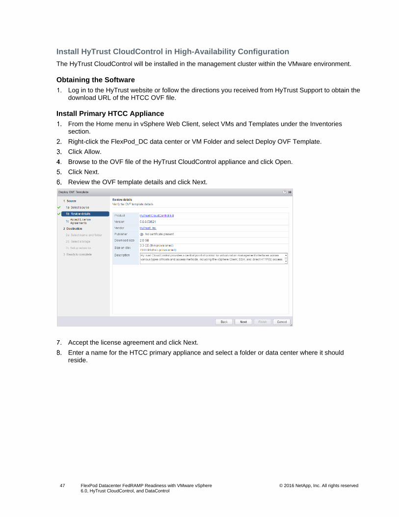
Reviewed by
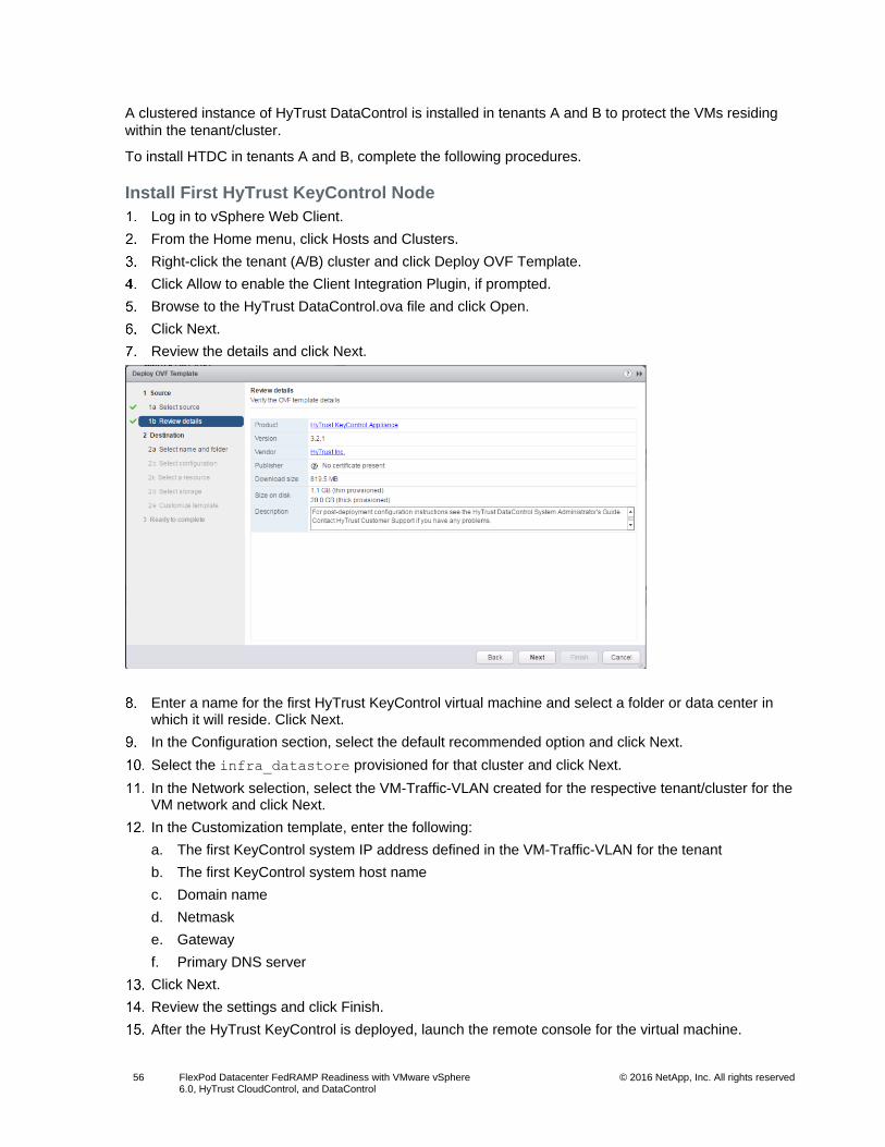
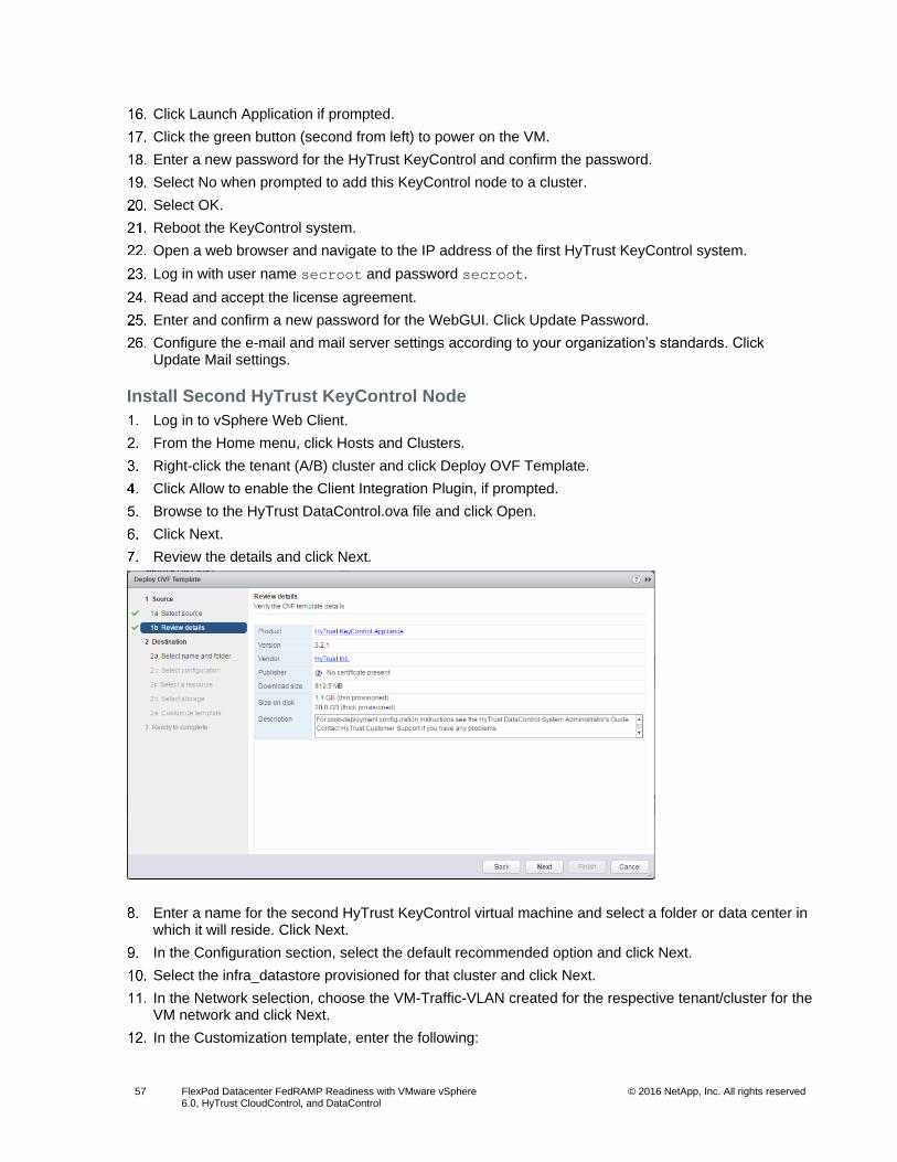
Page 2
2 FlexPod Datacenter FedRAMP Readiness with VMware vSphere 6.0, HyTrust CloudControl, and DataControl
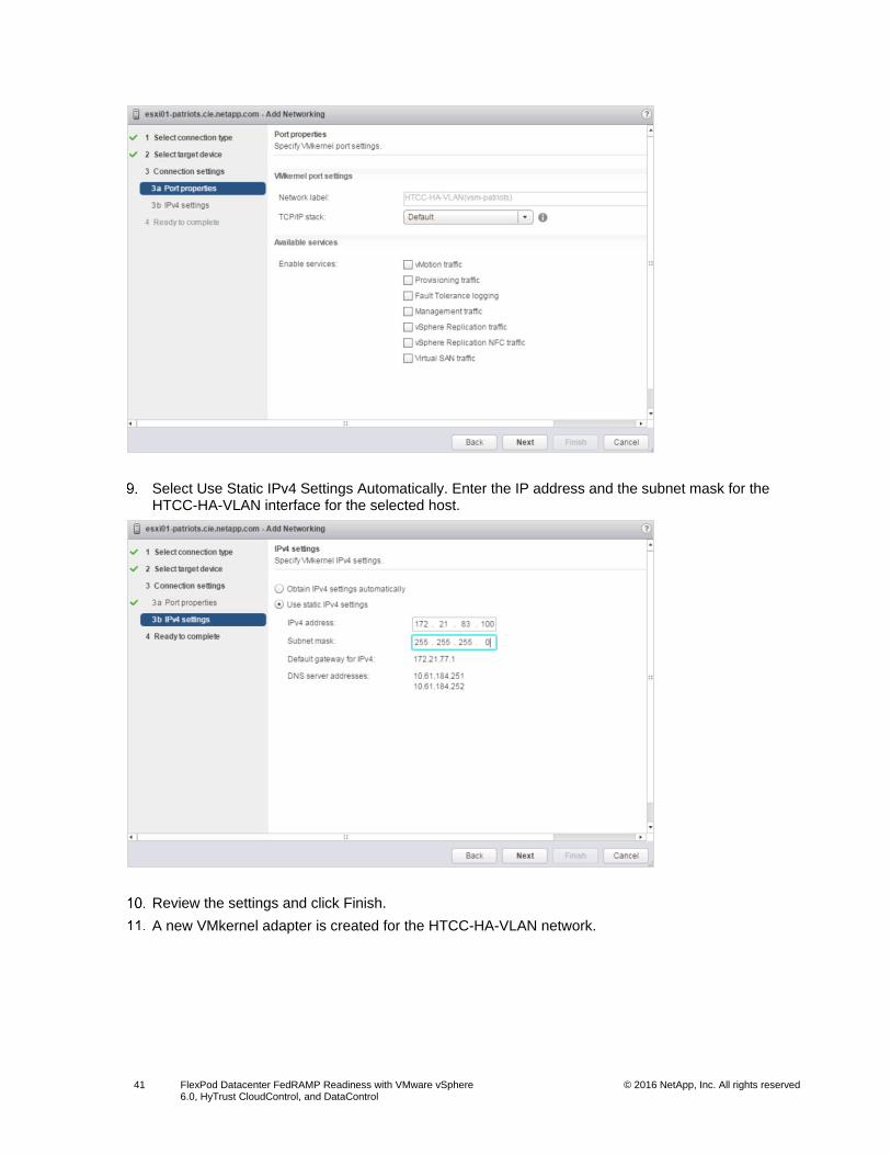
© 2016 NetApp, Inc. All rights reserved
TABLE OF CONTENTS
1 Program Summary................................................................................................................................ 4
2 Solution Overview ................................................................................................................................ 4
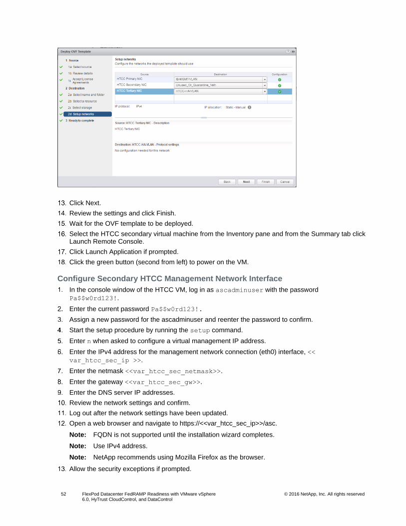
2.1 Solution Technology ....................................................................................................................................... 4
2.2 Use Case Summary ........................................................................................................................................ 7
3 Secure Multi-Tenancy and Data Management ................................................................................... 7
4 Technology Requirements .................................................................................................................. 8
4.1 Hardware Requirements ................................................................................................................................. 8
4.2 Software Requirements .................................................................................................................................. 8
5 Deployment Procedures ...................................................................................................................... 9
5.1 Cisco Nexus Configuration.............................................................................................................................. 9
5.2 NetApp Storage Configuration—Part I .......................................................................................................... 11
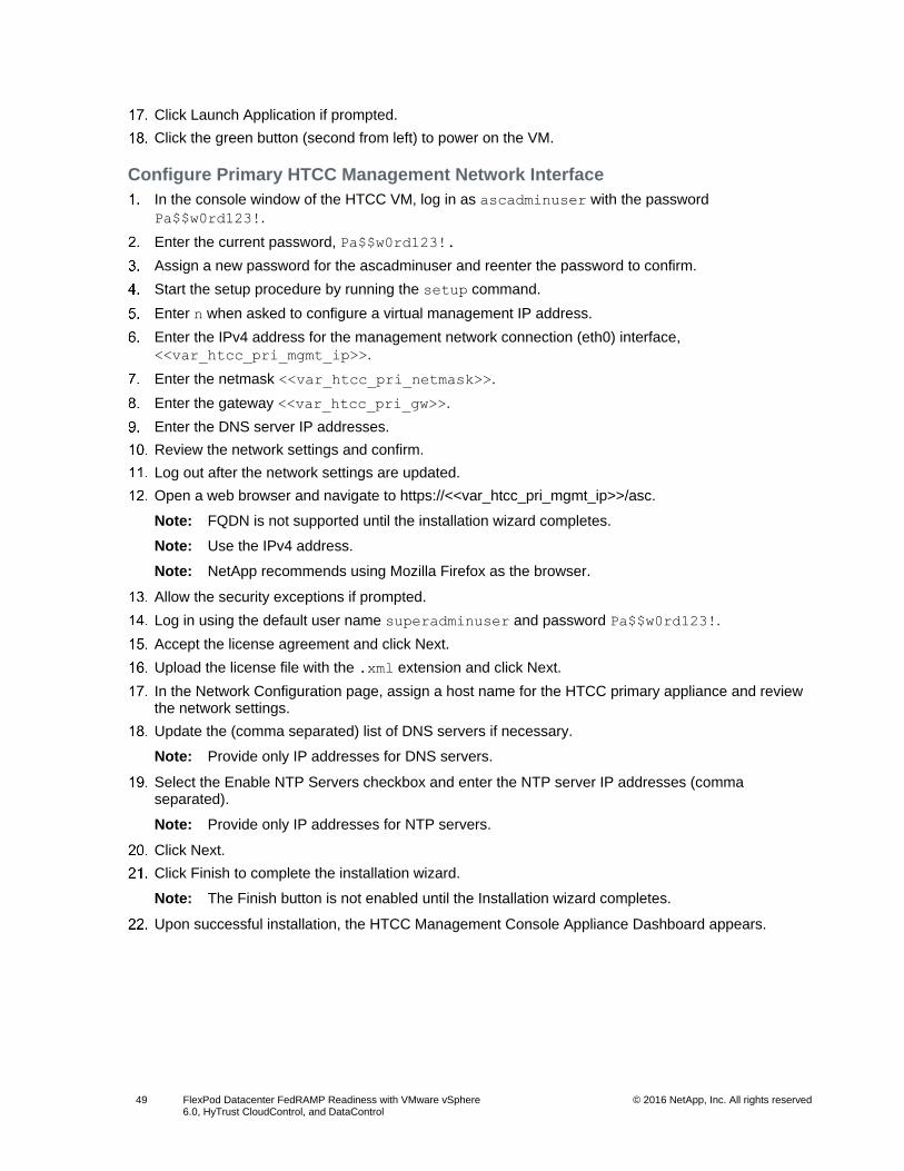
5.3 Cisco UCS Configuration .............................................................................................................................. 18
5.4 NetApp Storage Configuration—Part II ......................................................................................................... 38
5.5 VMware vSphere 6.0 Setup .......................................................................................................................... 39
5.6 Cisco Nexus 1000v VSM Configuration ........................................................................................................ 43
5.7 HyTrust CloudControl Installation and Configuration .................................................................................... 46
5.8 HyTrust DataControl Installation and Configuration ...................................................................................... 55
5.9 Set VM Restart Priority ................................................................................................................................. 59
6 FedRAMP Security Controls .............................................................................................................. 60
7 Conclusion .......................................................................................................................................... 60
References ................................................................................................................................................. 60
LIST OF TABLES
Table 1) Hardware requirements. ................................................................................................................................... 8
Table 2) Software requirements. .................................................................................................................................... 8
Table 3) iSCSI LIFs for iSCSI IQN. .............................................................................................................................. 38
Table 4) vNIC iSCSI IQNs for fabric A and fabric B. ..................................................................................................... 38
Table 5) VMKernel ports. .............................................................................................................................................. 39
Table 6) FedRAMP moderate impact security controls. ............................................................................................... 60
LIST OF FIGURES
Figure 1) FlexPod Datacenter architecture. .................................................................................................................... 5
Figure 2) FlexPod Datacenter design with HyTrust CloudControl. ................................................................................. 6
Page 3
3 FlexPod Datacenter FedRAMP Readiness with VMware vSphere 6.0, HyTrust CloudControl, and DataControl
© 2016 NetApp, Inc. All rights reserved
Figure 3) FlexPod Datacenter design with HyTrust DataControl. ................................................................................... 7
Page 4
4 FlexPod Datacenter FedRAMP Readiness with VMware vSphere 6.0, HyTrust CloudControl, and DataControl
© 2016 NetApp, Inc. All rights reserved
1 Program Summary
FlexPod® Datacenter is a predesigned, best practice data center architecture that is built on the Cisco
Unified Computing System (Cisco UCS), Cisco Nexus family of switches, and NetApp® fabric-attached
storage (FAS) systems. The FlexPod Datacenter solution is tailored to be the infrastructure backbone of
various public/private and hybrid cloud environments.
The Federal Risk and Authorization Management Program (FedRAMP) is a United States
governmentwide program that provides a standardized approach to security assessment, authorization,
and continuous monitoring for cloud products and services. This approach uses a “do once, use many
times” framework that saves an estimated 30% to 40% of government costs and the time and staff
required to conduct redundant agency security assessments. FedRAMP is the result of close
collaboration with cybersecurity and cloud experts from the General Services Administration, National
Institute of Standards and Technology, Department of Homeland Security, Department of Defense,
National Security Agency, Office of Management and Budget, the Federal Chief Information Officer
Council and its working groups, and private industry.
For more information about FedRAMP, go to https://www.fedramp.gov.
The FlexPod Datacenter solution was assessed for FedRAMP readiness. This document provides a
detailed overview of the information system that was audited as part of the program.
2 Solution Overview
FlexPod Datacenter lets you consolidate several siloed or independent workloads and host them on the
same physical infrastructure. Although this capability reduces the overall cost of implementing a data
center, it comes with the added challenges of secure management of data belonging to different
workloads and tenants.
The FlexPod Datacenter solution described in this document addresses these challenges. The base
infrastructure is built using the following guides:
FlexPod Datacenter with Cisco UCS 6300 Fabric Interconnect and VMware vSphere 6.0 U1 Design Guide
FlexPod Datacenter with Cisco UCS 6300 Fabric Interconnect and VMware vSphere 6.0 U1 Deployment Guide
The additional steps to implement secure multi-tenancy are covered in this document.
2.1 Solution Technology
FlexPod Datacenter
The FlexPod Datacenter solution combines NetApp storage systems, Cisco Unified Computing System
(Cisco UCS) servers, and Cisco Nexus fabric into a single flexible architecture. The FlexPod integrated
infrastructure leads in efficiency and flexibility, scaling and flexing as needed, with validated designs that
reduce deployment time, project risk, and the cost of IT.
In this deployment, the FlexPod Datacenter solution is treated as the core infrastructure-as-a-service
component. In addition, the HyTrust CloudControl and HyTrust DataControl software suites enable
FlexPod readiness for FedRAMP environments.
More information about the FlexPod Datacenter design is available in the Design Guide.
Figure 1 represents the FlexPod Datacenter solution that was used in this report.
Page 5
5 FlexPod Datacenter FedRAMP Readiness with VMware vSphere 6.0, HyTrust CloudControl, and DataControl
© 2016 NetApp, Inc. All rights reserved
Figure 1) FlexPod Datacenter architecture.
HyTrust CloudControl
The HyTrust CloudControl (HTCC) appliance is a secure hardened operating system built on the CentOS
platform. HTCC serves as a proxy to the VMware vCenter management platform and enhances the
platform with forensic grade logging and advanced administrative control. With HTCC’s granular role-
based access control (RBAC), administrative functions can be easily set to control permissions on a
virtual object level. HTCC applies smart labels to enable further segregation of virtual objects by
constraining object access based on certain labels. HTCC offers two-person integrity for destructive
actions on virtual machines through the secondary approval function.
HTCC offers automated compliance validation and implementation for VMware ESXi hosts. Variables can
be set and then applied to each host so that the host security posture complies with the required baseline
of the standard(s). HTCC can use Intel Trusted Execution Technology (TXT) to enable trusted compute
pools by labeling hosts and configuring virtual machines to run only on a host that has the correct label.
HTCC is deployed in the mapped mode and as a cluster configuration. In the mapped mode, all the hosts
that need to be protected by HTCC are configured with a published IP (PIP). This PIP is used by users
and clients to access the hosts.
HTCC is deployed as a transparent proxy and sits between the users and all management interfaces to
the protected hosts. From this central vantage point, HTCC intercepts and logs all administrative requests
Page 6
6 FlexPod Datacenter FedRAMP Readiness with VMware vSphere 6.0, HyTrust CloudControl, and DataControl
© 2016 NetApp, Inc. All rights reserved
coming through the PIP and enforces role- and resource-based policies that protect workloads from
unauthorized access.
A private cluster network is set up on a dedicated VLAN for the HTCC cluster nodes to communicate with
each other.
HTCC is integrated with an Active Directory/Domain instance to apply the user identities and privileges
extended to each user. Also, HTCC provides a set of access controls to users that can be configured to
have specific privileges in the virtual infrastructure space.
Figure 2 is a representation of HyTrust CloudControl integrated with the VMware virtual infrastructure,
which is deployed on FlexPod.
Figure 2) FlexPod Datacenter design with HyTrust CloudControl.
HyTrust DataControl
HyTrust DataControl (HTDC) provides encryption of virtual machine data while it is in motion and at rest.
HTDC is deployed as a virtual appliance in a high-availability configuration. The solution includes three
critical components: Key Control, Policy Engine, and Policy Agent.
Administrators can configure or modify encryption policies through the Policy Engine; the Policy Engine
then collects the rules for the Key Controller. The Key Controller in turn makes sure that the Policy Agent
(which resides in the VM/workload) executes on these policies by managing encryption key creation,
renewals, and destruction.
Figure 3 illustrates how HTDC protects the data of the VMs running on various tenants within the FlexPod
environment.
Page 7
7 FlexPod Datacenter FedRAMP Readiness with VMware vSphere 6.0, HyTrust CloudControl, and DataControl
© 2016 NetApp, Inc. All rights reserved
Figure 3) FlexPod Datacenter design with HyTrust DataControl.
2.2 Use Case Summary
The following use cases were identified as the most significant and essential requirements in a cloud
service provider scenario and were implemented using the FlexPod Datacenter solution and HyTrust:
Secure multi-tenancy
Secure data management
3 Secure Multi-Tenancy and Data Management
The FlexPod Datacenter solution provides secure multi-tenancy and data management capabilities. This
capability is achieved by implementing logical separation and access control within each component of
the solution. A brief description of how this capability was achieved within each layer of the FlexPod stack
follows.
Storage
Multiple logical storage controllers were created by using storage virtual machines (SVMs) to cater to the
storage needs of tenants. Each tenant was mapped to an SVM for all its storage requirements, and the
resources that were assigned to an SVM were not shared with any other coexisting SVM. The SVMs also
had their own set of users and administrators. Multiple logical interfaces (LIFs) were configured for each
SVM to handle iSCSI and NFS data traffic on dedicated VLANs.
Network
Each tenant within the FlexPod platform was provided with dedicated VLANs for all management and
data traffic. These VLANs are not routable and therefore there is no communication between any two
VLANs in the infrastructure. All the traffic using the data VLANs was kept private to the infrastructure and
each tenant was provided with a management VLAN for external access. This network configuration is
set up on both Cisco Nexus 9000 and 1000v switches.
Compute
The Cisco UCS infrastructure is split into multiple organizations and each organization corresponds to a
tenant. The network interface configurations for the vNICS and iSCSI vNICS were set up as per the
Page 8
8 FlexPod Datacenter FedRAMP Readiness with VMware vSphere 6.0, HyTrust CloudControl, and DataControl
© 2016 NetApp, Inc. All rights reserved
VLANs assigned to each tenant. Thus, network segregation is also achieved at the Cisco UCS layer. The
Cisco UCS organizations are also configured to have their own MAC pools, iSCSI initiator pools, boot
policies, BIOS policies, and so on. This configuration provides complete isolation from other tenants and
their resources.
VMware vSphere
Built on top of the above defined infrastructure, the VMware vSphere environment is configured to use the
assigned resources. Dedicated ESXi clusters are created for each tenant and the hosts within each
tenant have their own datastores and network resources. VM-to-host affinity rules are configured to make
sure that the VMs do not accidentally attempt to move to a host assigned to a different tenant. Even if
such a move is attempted, the operation will fail because of unavailability or lack of connectivity to
required port groups and datastores.
Secure Data Management
The secure data management capabilities are provided by NetApp Data ONTAP® software and HyTrust
DataControl. Data ONTAP provides secure multi-tenancy for the storage resources and DataControl
encrypts the virtual machine data of all the virtual machines in a tenant. In addition to DataControl,
NetApp Storage Encryption drives can also provide drive encryption for data at rest.
4 Technology Requirements
This section covers the technology requirements for the FlexPod Datacenter FedRAMP Readiness with
VMware vSphere 6.0, HyTrust CloudControl and DataControl solution.
4.1 Hardware Requirements
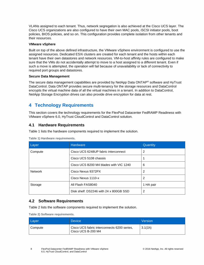
Table 1 lists the hardware components required to implement the solution.
Table 1) Hardware requirements.
Layer Hardware Quantity
Compute Cisco UCS 6248UP fabric interconnect 2
Cisco UCS 5108 chassis 1
Cisco UCS B200 M4 blades with VIC 1240 6
Network Cisco Nexus 9372PX 2
Cisco Nexus 1110-x 2
Storage All Flash FAS8040 1 HA pair
Disk shelf: DS2246 with 24 x 800GB SSD 2
4.2 Software Requirements
Table 2 lists the software components required to implement the solution.
Table 2) Software requirements.
Layer Device Version
Compute Cisco UCS fabric interconnects 6200 series, Cisco UCS B-200 M4
3.1(1h)
Page 9
9 FlexPod Datacenter FedRAMP Readiness with VMware vSphere 6.0, HyTrust CloudControl, and DataControl
© 2016 NetApp, Inc. All rights reserved
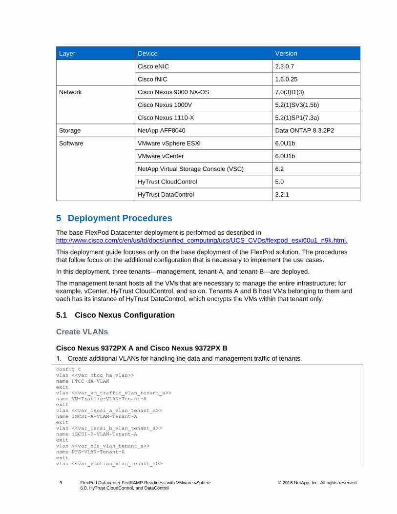
Layer Device Version
Cisco eNIC 2.3.0.7
Cisco fNIC 1.6.0.25
Network Cisco Nexus 9000 NX-OS 7.0(3)I1(3)
Cisco Nexus 1000V 5.2(1)SV3(1.5b)
Cisco Nexus 1110-X 5.2(1)SP1(7.3a)
Storage NetApp AFF8040 Data ONTAP 8.3.2P2
Software VMware vSphere ESXi 6.0U1b
VMware vCenter 6.0U1b
NetApp Virtual Storage Console (VSC) 6.2
HyTrust CloudControl 5.0
HyTrust DataControl 3.2.1
5 Deployment Procedures
The base FlexPod Datacenter deployment is performed as described in
http://www.cisco.com/c/en/us/td/docs/unified_computing/ucs/UCS_CVDs/flexpod_esxi60u1_n9k.html.
This deployment guide focuses only on the base deployment of the FlexPod solution. The procedures
that follow focus on the additional configuration that is necessary to implement the use cases.
In this deployment, three tenants—management, tenant-A, and tenant-B—are deployed.
The management tenant hosts all the VMs that are necessary to manage the entire infrastructure; for
example, vCenter, HyTrust CloudControl, and so on. Tenants A and B host VMs belonging to them and
each has its instance of HyTrust DataControl, which encrypts the VMs within that tenant only.
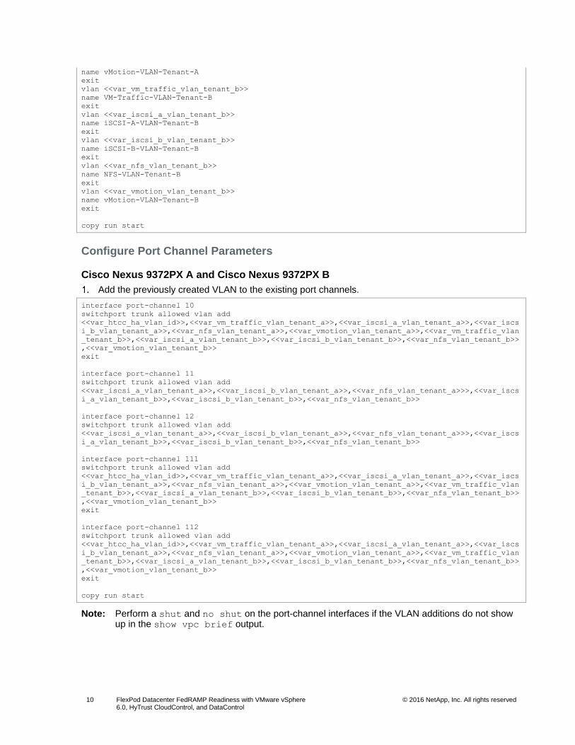
5.1 Cisco Nexus Configuration
Create VLANs
Cisco Nexus 9372PX A and Cisco Nexus 9372PX B
Create additional VLANs for handling the data and management traffic of tenants.
config t
vlan <<var_htcc_ha_vlan>>
name HTCC-HA-VLAN
exit
vlan <<var_vm_traffic_vlan_tenant_a>>
name VM-Traffic-VLAN-Tenant-A
exit
vlan <<var_iscsi_a_vlan_tenant_a>>
name iSCSI-A-VLAN-Tenant-A
exit
vlan <<var_iscsi_b_vlan_tenant_a>>
name iSCSI-B-VLAN-Tenant-A
exit
vlan <<var_nfs_vlan_tenant_a>>
name NFS-VLAN-Tenant-A
exit
vlan <<var_vmotion_vlan_tenant_a>>
Page 10
10 FlexPod Datacenter FedRAMP Readiness with VMware vSphere 6.0, HyTrust CloudControl, and DataControl
© 2016 NetApp, Inc. All rights reserved
name vMotion-VLAN-Tenant-A
exit
vlan <<var_vm_traffic_vlan_tenant_b>>
name VM-Traffic-VLAN-Tenant-B
exit
vlan <<var_iscsi_a_vlan_tenant_b>>
name iSCSI-A-VLAN-Tenant-B
exit
vlan <<var_iscsi_b_vlan_tenant_b>>
name iSCSI-B-VLAN-Tenant-B
exit
vlan <<var_nfs_vlan_tenant_b>>
name NFS-VLAN-Tenant-B
exit
vlan <<var_vmotion_vlan_tenant_b>>
name vMotion-VLAN-Tenant-B
exit
copy run start
Configure Port Channel Parameters
Cisco Nexus 9372PX A and Cisco Nexus 9372PX B
Add the previously created VLAN to the existing port channels.
interface port-channel 10
switchport trunk allowed vlan add
<<var_htcc_ha_vlan_id>>,<<var_vm_traffic_vlan_tenant_a>>,<<var_iscsi_a_vlan_tenant_a>>,<<var_iscs
i_b_vlan_tenant_a>>,<<var_nfs_vlan_tenant_a>>,<<var_vmotion_vlan_tenant_a>>,<<var_vm_traffic_vlan
_tenant_b>>,<<var_iscsi_a_vlan_tenant_b>>,<<var_iscsi_b_vlan_tenant_b>>,<<var_nfs_vlan_tenant_b>>
,<<var_vmotion_vlan_tenant_b>>
exit
interface port-channel 11
switchport trunk allowed vlan add
<<var_iscsi_a_vlan_tenant_a>>,<<var_iscsi_b_vlan_tenant_a>>,<<var_nfs_vlan_tenant_a>>>,<<var_iscs
i_a_vlan_tenant_b>>,<<var_iscsi_b_vlan_tenant_b>>,<<var_nfs_vlan_tenant_b>>
interface port-channel 12
switchport trunk allowed vlan add
<<var_iscsi_a_vlan_tenant_a>>,<<var_iscsi_b_vlan_tenant_a>>,<<var_nfs_vlan_tenant_a>>>,<<var_iscs
i_a_vlan_tenant_b>>,<<var_iscsi_b_vlan_tenant_b>>,<<var_nfs_vlan_tenant_b>>
interface port-channel 111
switchport trunk allowed vlan add
<<var_htcc_ha_vlan_id>>,<<var_vm_traffic_vlan_tenant_a>>,<<var_iscsi_a_vlan_tenant_a>>,<<var_iscs
i_b_vlan_tenant_a>>,<<var_nfs_vlan_tenant_a>>,<<var_vmotion_vlan_tenant_a>>,<<var_vm_traffic_vlan
_tenant_b>>,<<var_iscsi_a_vlan_tenant_b>>,<<var_iscsi_b_vlan_tenant_b>>,<<var_nfs_vlan_tenant_b>>
,<<var_vmotion_vlan_tenant_b>>
exit
interface port-channel 112
switchport trunk allowed vlan add
<<var_htcc_ha_vlan_id>>,<<var_vm_traffic_vlan_tenant_a>>,<<var_iscsi_a_vlan_tenant_a>>,<<var_iscs
i_b_vlan_tenant_a>>,<<var_nfs_vlan_tenant_a>>,<<var_vmotion_vlan_tenant_a>>,<<var_vm_traffic_vlan
_tenant_b>>,<<var_iscsi_a_vlan_tenant_b>>,<<var_iscsi_b_vlan_tenant_b>>,<<var_nfs_vlan_tenant_b>>
,<<var_vmotion_vlan_tenant_b>>
exit
copy run start
Note: Perform a shut and no shut on the port-channel interfaces if the VLAN additions do not show up in the show vpc brief output.
Page 11
11 FlexPod Datacenter FedRAMP Readiness with VMware vSphere 6.0, HyTrust CloudControl, and DataControl
© 2016 NetApp, Inc. All rights reserved
5.2 NetApp Storage Configuration—Part I
In addition to the procedures described in the Cisco Valid Designs (CVD) document, complete the
procedures in this section to set up the storage system. Three SVMs will be created, one for each tenant.
Create Aggregates
An aggregate containing the root volume is created during the Data ONTAP setup process. To create
additional aggregates, determine the aggregate name, the node on which to create it, and the number of
disks that the aggregate will contain. You can also create multiple aggregates and allocate them to
different SVMs. In this deployment, the same aggregates are shared across SVMs.
To create the aggregates required for this solution, complete the following steps:
Run the following commands:
aggr create -aggregate aggr1_fas_01 -nodes <<var_node01>> -diskcount 15
aggr create -aggregate aggr1_fas_02 -nodes <<var_node02>> -diskcount 15
Note: Retain at least one disk (select the largest disk) in the configuration as a spare. A best practice is to have at least one spare for each disk type and size per controller.
Note: The aggregate cannot be created until disk zeroing completes. Run the aggr show command to display the aggregate creation status. Do not proceed until both aggr1_fas_01 and aggr1_fas_02 are online.
Disable NetApp Snapshot® copies for the two data aggregates that you created in step 1.
system node run -node <<var_node01>> aggr options aggr1_fas_01 nosnap on
system node run -node <<var_node02>> aggr options aggr1_fas_02 nosnap on
Delete any existing Snapshot copies for the two data aggregates.
system node run -node <<var_node01>> snap delete –A –a –f aggr1_fas_01
system node run -node <<var_node02>> snap delete –A –a –f aggr1_fas_01
Rename the root aggregate on node 01 to match the naming convention for this aggregate on node 02.
aggr show
aggr rename –aggregate aggr0 –newname <<var_node01_rootaggrname>>
Set Up Management Broadcast Domain
To set up the default broadcast domain for the management network interfaces, complete the following
step:
Run the following commands:
broadcast-domain remove-ports -broadcast-domain Default -ports <<var_node01>>:e0e,
<<var_node01>>:e0f, <<var_node01>>:e0g, <<var_node01>>:e0h, <<var_node01>>:e0j,
<<var_node01>>:e0k, <<var_node01>>:e0l, <<var_node02>>:e0e, <<var_node02>>:e0f,
<<var_node02>>:e0g, <<var_node02>>:e0h, <<var_node02>>:e0j, <<var_node02>>:e0k,
<<var_node02>>:e0l
broadcast-domain show
Create Broadcast Domains in Clustered Data ONTAP
To create a data broadcast domain with an MTU of 9,000 and a management broadcast domain with an MTU of 1,500, complete the following steps:
broadcast-domain create -broadcast-domain IB_MGMT -mtu 1500
broadcast-domain create -broadcast-domain Infra_NFS -mtu 9000
broadcast-domain create -broadcast-domain Infra_NFS_Tenant_A -mtu 9000
broadcast-domain create -broadcast-domain Infra_NFS_Tenant_B -mtu 9000
broadcast-domain create -broadcast-domain Infra_iSCSI-A -mtu 9000
Page 12
12 FlexPod Datacenter FedRAMP Readiness with VMware vSphere 6.0, HyTrust CloudControl, and DataControl
© 2016 NetApp, Inc. All rights reserved
broadcast-domain create -broadcast-domain Infra_iSCSI-A_Tenant_A -mtu 9000
broadcast-domain create -broadcast-domain Infra_iSCSI-A_Tenant_B -mtu 9000
broadcast-domain create -broadcast-domain Infra_iSCSI-B -mtu 9000
broadcast-domain create -broadcast-domain Infra_iSCSI-B_Tenant_A -mtu 9000
broadcast-domain create -broadcast-domain Infra_iSCSI-B_Tenant_B -mtu 9000
Create LACP Interface Groups
The ifgrp interface group requires two or more Ethernet interfaces and a switch that supports the Link
Aggregation Control Protocol (LACP). Therefore, confirm that the switch is configured properly.
To create interface groups, complete the following step:
Run the following commands:
ifgrp create -node <<var_node01>> -ifgrp a0a -distr-func port -mode multimode_lacp
ifgrp add-port -node <<var_node01>> -ifgrp a0a -port e0e
ifgrp add-port -node <<var_node01>> -ifgrp a0a -port e0g
ifgrp create -node <<var_node02>> -ifgrp a0a -distr-func port -mode multimode_lacp
ifgrp add-port -node <<var_node02>> -ifgrp a0a -port e0e
ifgrp add-port -node <<var_node02>> -ifgrp a0a -port e0g
ifgrp show
Note: All interfaces must be in the down state before being added to an interface group.
Note: The interface group name must follow the standard naming convention of <number><letter>, where:
<number> is an integer in the range of 0 to 999 without leading zeros.
<letter> is a lowercase letter.
Configure Jumbo Frames
To configure a clustered Data ONTAP network port to use jumbo frames (which usually have an MTU of
9,000 bytes), complete the following step:
From the cluster shell, run the following command:
network port modify -node * -port a0a -mtu 9000
WARNING: Changing the network port settings will cause a several second interruption in carrier.
Do you want to continue? {y|n}: y
Note: Modifications to an interface group cause the underlying physical ports to inherit the same configuration. If the ports are later removed from the interface group, the ports retain these same settings. However, the inverse is not true; modifying the individual ports does not modify the interface group of which the ports are a member.
Note: After the MTU for the interface group is set to 9,000, all new VLAN interfaces created on that interface group will also have an MTU of 9,000 bytes. Existing VLAN interfaces retain their original MTU after the ifgroup is changed.
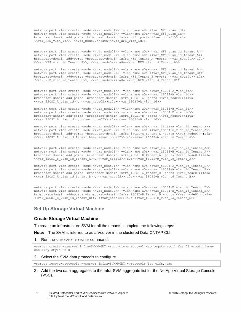
Create VLANs
To create NFS and iSCSI VLANs for all the tenants and add them to their respective broadcast domains,
complete the following step:
Run the following commands:
network port vlan create –node <<var_node01>> -vlan-name a0a-<<var_IB_MGMT_vlan_id>>
network port vlan create –node <<var_node02>> -vlan-name a0a-<<var_IB_MGMT_vlan_id>>
broadcast-domain add-ports -broadcast-domain IB-MGMT -ports <<var_node01>>:a0a-
<<var_IB_MGMT_vlan_id>>, <<var_node02>>:a0a-<<var_IB_MGMT_vlan_id>>
Page 13
13 FlexPod Datacenter FedRAMP Readiness with VMware vSphere 6.0, HyTrust CloudControl, and DataControl
© 2016 NetApp, Inc. All rights reserved
network port vlan create –node <<var_node01>> -vlan-name a0a-<<var_NFS_vlan_id>>
network port vlan create –node <<var_node02>> -vlan-name a0a-<<var_NFS_vlan_id>>
broadcast-domain add-ports -broadcast-domain Infra_NFS -ports <<var_node01>>:a0a-
<<var_NFS_vlan_id>>, <<var_node02>>:a0a-<<var_NFS_vlan_id>>
network port vlan create –node <<var_node01>> -vlan-name a0a-<<var_NFS_vlan_id_Tenant_A>>
network port vlan create –node <<var_node02>> -vlan-name a0a-<<var_NFS_vlan_id_Tenant_A>>
broadcast-domain add-ports -broadcast-domain Infra_NFS_Tenant_A -ports <<var_node01>>:a0a-
<<var_NFS_vlan_id_Tenant_A>>, <<var_node02>>:a0a-<<var_NFS_vlan_id_Tenant_A>>
network port vlan create –node <<var_node01>> -vlan-name a0a-<<var_NFS_vlan_id_Tenant_B>>
network port vlan create –node <<var_node02>> -vlan-name a0a-<<var_NFS_vlan_id_Tenant_B>>
broadcast-domain add-ports -broadcast-domain Infra_NFS_Tenant_B -ports <<var_node01>>:a0a-
<<var_NFS_vlan_id_Tenant_B>>, <<var_node02>>:a0a-<<var_NFS_vlan_id_Tenant_B>>
network port vlan create -node <<var_node01>> -vlan-name a0a-<<var_iSCSI-A_vlan_id>>
network port vlan create -node <<var_node02>> -vlan-name a0a-<<var_iSCSI-A_vlan_id>>
broadcast-domain add-ports -broadcast-domain Infra_iSCSI-A -ports <<var_node01>>:a0a-
<<var_iSCSI_A_vlan_id>>, <<var_node02>>:a0a-<<var_iSCSI-A_vlan_id>>
network port vlan create -node <<var_node01>> -vlan-name a0a-<<var_iSCSI-B_vlan_id>>
network port vlan create -node <<var_node02>> -vlan-name a0a-<<var_iSCSI-B_vlan_id>>
broadcast-domain add-ports -broadcast-domain Infra_iSCSI-B -ports <<var_node01>>:a0a-
<<var_iSCSI_B_vlan_id>>, <<var_node02>>:a0a-<<var_iSCSI-B_vlan_id>>
network port vlan create -node <<var_node01>> -vlan-name a0a-<<var_iSCSI-A_vlan_id_Tenant_A>>
network port vlan create -node <<var_node02>> -vlan-name a0a-<<var_iSCSI-A_vlan_id_Tenant_A>>
broadcast-domain add-ports -broadcast-domain Infra_iSCSI-A_Tenant_A -ports <<var_node01>>:a0a-
<<var_iSCSI_A_vlan_id_Tenant_A>>, <<var_node02>>:a0a-<<var_iSCSI-A_vlan_id_Tenant_A>>
network port vlan create -node <<var_node01>> -vlan-name a0a-<<var_iSCSI-B_vlan_id_Tenant_A>>
network port vlan create -node <<var_node02>> -vlan-name a0a-<<var_iSCSI-B_vlan_id_Tenant_A>>
broadcast-domain add-ports -broadcast-domain Infra_iSCSI-B_Tenant_A -ports <<var_node01>>:a0a-
<<var_iSCSI_B_vlan_id_Tenant_A>>, <<var_node02>>:a0a-<<var_iSCSI-B_vlan_id_Tenant_A>>
network port vlan create -node <<var_node01>> -vlan-name a0a-<<var_iSCSI-A_vlan_id_Tenant_B>>
network port vlan create -node <<var_node02>> -vlan-name a0a-<<var_iSCSI-A_vlan_id_Tenant_B>>
broadcast-domain add-ports -broadcast-domain Infra_iSCSI-A_Tenant_B -ports <<var_node01>>:a0a-
<<var_iSCSI_A_vlan_id_Tenant_B>>, <<var_node02>>:a0a-<<var_iSCSI-A_vlan_id_Tenant_B>>
network port vlan create -node <<var_node01>> -vlan-name a0a-<<var_iSCSI-B_vlan_id_Tenant_B>>
network port vlan create -node <<var_node02>> -vlan-name a0a-<<var_iSCSI-B_vlan_id_Tenant_B>>
broadcast-domain add-ports -broadcast-domain Infra_iSCSI-B_Tenant_B -ports <<var_node01>>:a0a-
<<var_iSCSI_B_vlan_id_Tenant_B>>, <<var_node02>>:a0a-<<var_iSCSI-B_vlan_id_Tenant_B>>
Set Up Storage Virtual Machine
Create Storage Virtual Machine
To create an infrastructure SVM for all the tenants, complete the following steps:
Note: The SVM is referred to as a Vserver in the clustered Data ONTAP CLI.
Run the vserver create command:
vserver create -vserver Infra-SVM-MGMT -rootvolume rootvol -aggregate aggr1_fas_01 -rootvolume-
security-style unix
Select the SVM data protocols to configure.
vserver remove-protocols –vserver Infra-SVM-MGMT -protocols fcp,cifs,ndmp
Add the two data aggregates to the Infra-SVM aggregate list for the NetApp Virtual Storage Console (VSC).
Page 14
14 FlexPod Datacenter FedRAMP Readiness with VMware vSphere 6.0, HyTrust CloudControl, and DataControl
© 2016 NetApp, Inc. All rights reserved
vserver modify -vserver Infra-SVM-MGMT -aggr-list aggr1_fas_01, aggr1_fas_02
Enable and run the NFS protocol in the Infra-SVM.
nfs create -vserver Infra-SVM-MGMT -udp disabled
Enable the SVM vstorage parameter for the NetApp NFS VAAI plug-in.
vserver nfs modify –vserver Infra-SVM-MGMT –vstorage enabled
vserver nfs show
Repeat steps 1 to 5 to create Infra-SVM-Tenant-A and Infra-SVM-Tenant-B.
Note: Make sure to replace the correct SVM name in the -vserver option in the previous steps.
Create Load-Sharing Mirror of SVM Root Volume
To create a load-sharing mirror of an SVM root volume for all the tenants, complete the following steps:
Create a volume to be the load-sharing mirror of the root volume of the infrastructure SVM on each node.
volume create –vserver Infra-SVM-MGMT –volume rootvol_m01 –aggregate aggr1_fas_01 –size 1GB –type
DP
volume create –vserver Infra-SVM-MGMT –volume rootvol_m02 –aggregate aggr1_fas_02 –size 1GB –type
DP
Create a job schedule to update the root volume mirror relationships every 15 minutes.
job schedule interval create -name 15min -minutes 15
Create the mirroring relationships.
snapmirror create –source-path //Infra-SVM-MGMT/rootvol –destination-path //Infra-SVM-
MGMT/rootvol_m01 –type LS -schedule 15min
snapmirror create –source-path //Infra-SVM-MGMT/rootvol –destination-path //Infra-SVM-
MGMT/rootvol_m02 –type LS -schedule 15min
Initialize the mirroring relationship.
snapmirror initialize-ls-set –source-path //Infra-SVM-MGMT/rootvol
Repeat steps 1 to 4 to create a load-sharing mirror of the SVM root volume for Infra-SVM-Tenant-
A and Infra-SVM-Tenant-B.
Note: Make sure to replace the correct SVM name in the -vserver option in the previous steps.
Create iSCSI Service
To create the iSCSI service, complete the following step:
Create the iSCSI service on each SVM. This command also starts the iSCSI service and sets the iSCSI IQN for the SVM.
iscsi create -vserver Infra-SVM-MGMT
iscsi create -vserver Infra-SVM-Tenant-A
iscsi create -vserver Infra-SVM-Tenant-B
iscsi show
Configure NFSv3
To configure NFSv3 on the SVM, complete the following steps.
Create a rule for each ESXi host in the default export policy. Assign a rule for each ESXi host created so that each host has its own rule index. For example, the first ESXi host has rule index 1, the second ESXi host has rule index 2, and so on.
Page 15
15 FlexPod Datacenter FedRAMP Readiness with VMware vSphere 6.0, HyTrust CloudControl, and DataControl
© 2016 NetApp, Inc. All rights reserved
vserver export-policy rule create -vserver Infra-SVM-MGMT -policyname default -ruleindex 1 -
clientmatch <<var_esxi_host1_nfs_ip>> -rorule sys -rwrule sys -superuser sys -allow-suid false
vserver export-policy rule create -vserver Infra-SVM-MGMT -policyname default -ruleindex 2 -
clientmatch <<var_esxi_host2_nfs_ip>> -rorule sys -rwrule sys -superuser sys -allow-suid false
vserver export-policy rule create -vserver Infra-SVM-Tenant-A -policyname default -ruleindex 1 -
clientmatch <<var_esxi_host3_nfs_ip>> -rorule sys -rwrule sys -superuser sys -allow-suid false
vserver export-policy rule create -vserver Infra-SVM-Tenant-A -policyname default -ruleindex 2 -
clientmatch <<var_esxi_host4_nfs_ip>> -rorule sys -rwrule sys -superuser sys -allow-suid false
vserver export-policy rule create -vserver Infra-SVM-Tenant-B -policyname default -ruleindex 1 -
clientmatch <<var_esxi_host5_nfs_ip>> -rorule sys -rwrule sys -superuser sys -allow-suid false
vserver export-policy rule create -vserver Infra-SVM-Tenant-B -policyname default -ruleindex 2 -
clientmatch <<var_esxi_host6_nfs_ip>> -rorule sys -rwrule sys -superuser sys -allow-suid false
Assign the default export policy to the infrastructure SVM root volume.
volume modify -vserver Infra-SVM-MGMT -volume rootvol -policy default
volume modify -vserver Infra-SVM-Tenant-A -volume rootvol -policy default
volume modify -vserver Infra-SVM-Tenant-B -volume rootvol -policy default
Create FlexVol Volumes
To create a NetApp FlexVol® volume, complete the following step:
Run the following commands:
volume create -vserver Infra-SVM-MGMT -volume infra_datastore_1 -aggregate aggr1_fas_02 -size 1TB
-state online -policy default -junction-path /infra_datastore_1 -space-guarantee none -percent-
snapshot-space 0
volume create -vserver Infra-SVM-MGMT -volume infra_swap -aggregate aggr1_fas_01 -size 100GB -
state online -policy default -junction-path /infra_swap -space-guarantee none -percent-snapshot-
space 0 -snapshot-policy none
volume create -vserver Infra-SVM-MGMT -volume esxi_boot -aggregate aggr1_fas_01 -size 500GB -
state online -policy default -space-guarantee none -percent-snapshot-space 0
snapmirror update-ls-set -source-path //Infra-SVM-MGMT/rootvol
volume create -vserver Infra-SVM-Tenant-A -volume infra_datastore_1_tenant_A -aggregate
aggr1_fas_02 -size 1TB -state online -policy default -junction-path /infra_datastore_1_A -space-
guarantee none -percent-snapshot-space 0
volume create -vserver Infra-SVM-MGMT -volume infra_swap_tenant_A -aggregate aggr1_fas_01 -size
100GB -state online -policy default -junction-path /infra_swap_tenant_A -space-guarantee none -
percent-snapshot-space 0 -snapshot-policy none
volume create -vserver Infra-SVM-MGMT -volume esxi_boot_tenant_A -aggregate aggr1_fas_01 -size
500GB -state online -policy default -space-guarantee none -percent-snapshot-space 0
snapmirror update-ls-set -source-path //Infra-SVM-Tenant_A/rootvol
volume create -vserver Infra-SVM-Tenant-A -volume infra_datastore_1_tenant_B -aggregate
aggr1_fas_02 -size 1TB -state online -policy default -junction-path /infra_datastore_1_B -space-
guarantee none -percent-snapshot-space 0
volume create -vserver Infra-SVM-MGMT -volume infra_swap_tenant_B -aggregate aggr1_fas_01 -size
100GB -state online -policy default -junction-path /infra_swap_tenant_B -space-guarantee none -
percent-snapshot-space 0 -snapshot-policy none
volume create -vserver Infra-SVM-MGMT -volume esxi_boot_tenant_B -aggregate aggr1_fas_01 -size
500GB -state online -policy default -space-guarantee none -percent-snapshot-space 0
snapmirror update-ls-set -source-path //Infra-SVM-Tenant_B/rootvol
Page 16
16 FlexPod Datacenter FedRAMP Readiness with VMware vSphere 6.0, HyTrust CloudControl, and DataControl
© 2016 NetApp, Inc. All rights reserved
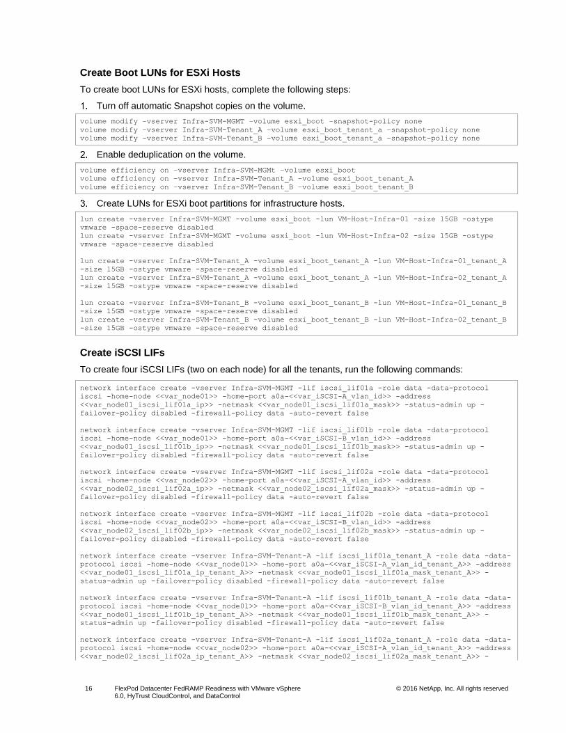
Create Boot LUNs for ESXi Hosts
To create boot LUNs for ESXi hosts, complete the following steps:
Turn off automatic Snapshot copies on the volume.
volume modify –vserver Infra-SVM-MGMT –volume esxi_boot –snapshot-policy none
volume modify –vserver Infra-SVM-Tenant_A –volume esxi_boot_tenant_a –snapshot-policy none
volume modify –vserver Infra-SVM-Tenant_B –volume esxi_boot_tenant_a –snapshot-policy none
Enable deduplication on the volume.
volume efficiency on –vserver Infra-SVM-MGMt –volume esxi_boot
volume efficiency on –vserver Infra-SVM-Tenant_A –volume esxi_boot_tenant_A
volume efficiency on –vserver Infra-SVM-Tenant_B –volume esxi_boot_tenant_B
Create LUNs for ESXi boot partitions for infrastructure hosts.
lun create -vserver Infra-SVM-MGMT -volume esxi_boot -lun VM-Host-Infra-01 -size 15GB -ostype
vmware -space-reserve disabled
lun create -vserver Infra-SVM-MGMT -volume esxi_boot -lun VM-Host-Infra-02 -size 15GB -ostype
vmware -space-reserve disabled
lun create -vserver Infra-SVM-Tenant_A -volume esxi_boot_tenant_A -lun VM-Host-Infra-01_tenant_A
-size 15GB -ostype vmware -space-reserve disabled
lun create -vserver Infra-SVM-Tenant_A -volume esxi_boot_tenant_A -lun VM-Host-Infra-02_tenant_A
-size 15GB -ostype vmware -space-reserve disabled
lun create -vserver Infra-SVM-Tenant_B -volume esxi_boot_tenant_B -lun VM-Host-Infra-01_tenant_B
-size 15GB -ostype vmware -space-reserve disabled
lun create -vserver Infra-SVM-Tenant_B -volume esxi_boot_tenant_B -lun VM-Host-Infra-02_tenant_B
-size 15GB -ostype vmware -space-reserve disabled
Create iSCSI LIFs
To create four iSCSI LIFs (two on each node) for all the tenants, run the following commands:
network interface create -vserver Infra-SVM-MGMT -lif iscsi_lif01a -role data -data-protocol
iscsi -home-node <<var_node01>> -home-port a0a-<<var_iSCSI-A_vlan_id>> -address
<<var_node01_iscsi_lif01a_ip>> -netmask <<var_node01_iscsi_lif01a_mask>> -status-admin up -
failover-policy disabled -firewall-policy data -auto-revert false
network interface create -vserver Infra-SVM-MGMT -lif iscsi_lif01b -role data -data-protocol
iscsi -home-node <<var_node01>> -home-port a0a-<<var_iSCSI-B_vlan_id>> -address
<<var_node01_iscsi_lif01b_ip>> -netmask <<var_node01_iscsi_lif01b_mask>> -status-admin up -
failover-policy disabled -firewall-policy data -auto-revert false
network interface create -vserver Infra-SVM-MGMT -lif iscsi_lif02a -role data -data-protocol
iscsi -home-node <<var_node02>> -home-port a0a-<<var_iSCSI-A_vlan_id>> -address
<<var_node02_iscsi_lif02a_ip>> -netmask <<var_node02_iscsi_lif02a_mask>> -status-admin up -
failover-policy disabled -firewall-policy data -auto-revert false
network interface create -vserver Infra-SVM-MGMT -lif iscsi_lif02b -role data -data-protocol
iscsi -home-node <<var_node02>> -home-port a0a-<<var_iSCSI-B_vlan_id>> -address
<<var_node02_iscsi_lif02b_ip>> -netmask <<var_node02_iscsi_lif02b_mask>> -status-admin up -
failover-policy disabled -firewall-policy data -auto-revert false
network interface create -vserver Infra-SVM-Tenant-A -lif iscsi_lif01a_tenant_A -role data -data-
protocol iscsi -home-node <<var_node01>> -home-port a0a-<<var_iSCSI-A_vlan_id_tenant_A>> -address
<<var_node01_iscsi_lif01a_ip_tenant_A>> -netmask <<var_node01_iscsi_lif01a_mask_tenant_A>> -
status-admin up -failover-policy disabled -firewall-policy data -auto-revert false
network interface create -vserver Infra-SVM-Tenant-A -lif iscsi_lif01b_tenant_A -role data -data-
protocol iscsi -home-node <<var_node01>> -home-port a0a-<<var_iSCSI-B_vlan_id_tenant_A>> -address
<<var_node01_iscsi_lif01b_ip_tenant_A>> -netmask <<var_node01_iscsi_lif01b_mask_tenant_A>> -
status-admin up -failover-policy disabled -firewall-policy data -auto-revert false
network interface create -vserver Infra-SVM-Tenant-A -lif iscsi_lif02a_tenant_A -role data -data-
protocol iscsi -home-node <<var_node02>> -home-port a0a-<<var_iSCSI-A_vlan_id_tenant_A>> -address
<<var_node02_iscsi_lif02a_ip_tenant_A>> -netmask <<var_node02_iscsi_lif02a_mask_tenant_A>> -
Page 17
17 FlexPod Datacenter FedRAMP Readiness with VMware vSphere 6.0, HyTrust CloudControl, and DataControl
© 2016 NetApp, Inc. All rights reserved
status-admin up -failover-policy disabled -firewall-policy data -auto-revert false
network interface create -vserver Infra-SVM-Tenant-A -lif iscsi_lif02b_tenant_A -role data -data-
protocol iscsi -home-node <<var_node02>> -home-port a0a-<<var_iSCSI-B_vlan_id_tenant_A>> -address
<<var_node02_iscsi_lif02b_ip_tenant_A>> -netmask <<var_node02_iscsi_lif02b_mask_tenant_A>> -
status-admin up -failover-policy disabled -firewall-policy data -auto-revert false
network interface create -vserver Infra-SVM-Tenant-B -lif iscsi_lif01a_tenant_B -role data -data-
protocol iscsi -home-node <<var_node01>> -home-port a0a-<<var_iSCSI-A_vlan_id_tenant_B>> -address
<<var_node01_iscsi_lif01a_ip_tenant_B>> -netmask <<var_node01_iscsi_lif01a_mask_tenant_B>> -
status-admin up -failover-policy disabled -firewall-policy data -auto-revert false
network interface create -vserver Infra-SVM-Tenant-B -lif iscsi_lif01b_tenant_B -role data -data-
protocol iscsi -home-node <<var_node01>> -home-port a0a-<<var_iSCSI-B_vlan_id_tenant_B>> -address
<<var_node01_iscsi_lif01b_ip_tenant_B>> -netmask <<var_node01_iscsi_lif01b_mask_tenant_B>> -
status-admin up -failover-policy disabled -firewall-policy data -auto-revert false
network interface create -vserver Infra-SVM-Tenant-B -lif iscsi_lif02a_tenant_B -role data -data-
protocol iscsi -home-node <<var_node02>> -home-port a0a-<<var_iSCSI-A_vlan_id_tenant_B>> -address
<<var_node02_iscsi_lif02a_ip_tenant_B>> -netmask <<var_node02_iscsi_lif02a_mask_tenant_B>> -
status-admin up -failover-policy disabled -firewall-policy data -auto-revert false
network interface create -vserver Infra-SVM-Tenant-B -lif iscsi_lif02b_tenant_B -role data -data-
protocol iscsi -home-node <<var_node02>> -home-port a0a-<<var_iSCSI-B_vlan_id_tenant_B>> -address
<<var_node02_iscsi_lif02b_ip_tenant_B>> -netmask <<var_node02_iscsi_lif02b_mask_tenant_B>> -
status-admin up -failover-policy disabled -firewall-policy data -auto-revert false
network interface show
Create NFS LIFs
To create an NFS LIF for all the tenants, run the following commands:
network interface create -vserver Infra-SVM-MGMT -lif nfs_infra_datastore_1 -role data -data-
protocol nfs -home-node <<var_node01>> -home-port a0a-<<var_nfs_vlan_id>> -address
<<var_node01_nfs_lif_infra_datastore_1_ip>> -netmask
<<var_node01_nfs_lif_infra_datastore_1_mask>> -status-admin up -failover-policy broadcast-domain-
wide -firewall-policy data -auto-revert true
network interface create -vserver Infra-SVM-MGMT -lif nfs_infra_swap -role data -data-protocol
nfs -home-node <<var_node02>> -home-port a0a-<<var_nfs_vlan_id>> -address
<<var_node02_nfs_lif_infra_swap_ip>> -netmask <<var_node02_nfs_lif_infra_swap_mask>> -status-
admin up -failover-policy broadcast-domain-wide -firewall-policy data -auto-revert true
network interface create -vserver Infra-SVM-Tenant-A -lif nfs_infra_datastore_1_tenant_A -role
data -data-protocol nfs -home-node <<var_node01>> -home-port a0a-<<var_nfs_vlan_id_tenant_A>> -
address <<var_node01_nfs_lif_infra_datastore_1_ip_tenant_A>> -netmask
<<var_node01_nfs_lif_infra_datastore_1_mask_tenant_A>> -status-admin up -failover-policy
broadcast-domain-wide -firewall-policy data -auto-revert true
network interface create -vserver Infra-SVM-Tenant-A -lif nfs_infra_swap_tenant_A -role data -
data-protocol nfs -home-node <<var_node02>> -home-port a0a-<<var_nfs_vlan_id_tenant_A>> -address
<<var_node02_nfs_lif_infra_swap_ip_tenant_A>> -netmask
<<var_node02_nfs_lif_infra_swap_mask_tenant_A>> -status-admin up -failover-policy broadcast-
domain-wide -firewall-policy data -auto-revert true
network interface create -vserver Infra-SVM-Tenant-B -lif nfs_infra_datastore_1_tenant_B -role
data -data-protocol nfs -home-node <<var_node01>> -home-port a0a-<<var_nfs_vlan_id_tenant_B>> -
address <<var_node01_nfs_lif_infra_datastore_1_ip_tenant_B>> -netmask
<<var_node01_nfs_lif_infra_datastore_1_mask_tenant_B>> -status-admin up -failover-policy
broadcast-domain-wide -firewall-policy data -auto-revert true
network interface create -vserver Infra-SVM-Tenant-B -lif nfs_infra_swap_tenant_B -role data -
data-protocol nfs -home-node <<var_node02>> -home-port a0a-<<var_nfs_vlan_id_tenant_B>> -address
<<var_node02_nfs_lif_infra_swap_ip_tenant_B>> -netmask
<<var_node02_nfs_lif_infra_swap_mask_tenant_B>> -status-admin up -failover-policy broadcast-
domain-wide -firewall-policy data -auto-revert true
Page 18
18 FlexPod Datacenter FedRAMP Readiness with VMware vSphere 6.0, HyTrust CloudControl, and DataControl
© 2016 NetApp, Inc. All rights reserved
Add Infrastructure SVM Administrator
To add the infrastructure SVM administrator and SVM administration LIF in the out-of-band management
network for all the tenants, complete the following steps:
Run the following commands:
network interface create -vserver Infra-SVM-MGMT -lif vsmgmt -role data -data-protocol none -
home-node <<var_node02>> -home-port e0M -address <<var_svm_mgmt_ip>> -netmask
<<var_svm_mgmt_mask>> -status-admin up -failover-policy broadcast-domain-wide -firewall-policy
mgmt -auto-revert true
Note: The SVM management IP in this step should be in the same subnet as the storage cluster management IP.
Create a default route to allow the SVM management interface to reach the outside world.
network route create -vserver Infra-SVM-MGMT -destination 0.0.0.0/0 -gateway
<<var_svm_mgmt_gateway>>
network route show
Set a password for the SVM vsadmin user and unlock the user.
security login password -username vsadmin -vserver Infra-SVM-MGMT
Enter a new password: <<var_password>>
Enter it again: <<var_password>>
security login unlock -username vsadmin -vserver Infra-SVM-MGMT
Repeat the previous steps for all other tenants.
5.3 Cisco UCS Configuration
To configure the Cisco UCS environment to host multiple tenants, complete the procedures in this
section.
Create Organizations
In Cisco UCS Manager, click the Equipment tab in the navigation pane.
From the right pane, click New and select Create Organization from the drop-down list.
Enter a name for the organization and provide a description
Note: Create a total of three organizations to host the three tenants.
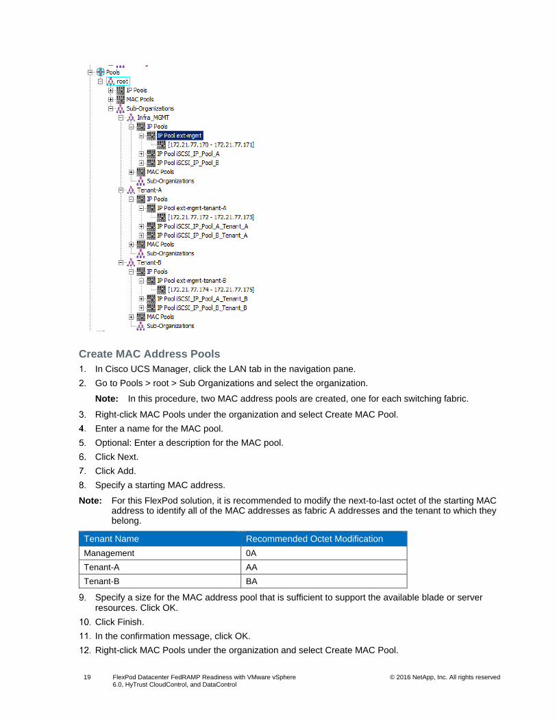
Create IP Pools for In-Band KVM Access
In Cisco UCS Manager, click the LAN tab in the navigation pane.
Go to Pools > root> Sub Organizations and select an organization.
Right-click IP Pools and select Create IP Pool.
Enter a name for the pool and click Next.
Click Add.
Enter the starting IP address of the block, the number of IP addresses required, and the subnet and gateway information. Click Next.
Click Finish to create the IP block.
Note: Create a total of three IPs for the three tenants within their respective organizations.
Page 19
19 FlexPod Datacenter FedRAMP Readiness with VMware vSphere 6.0, HyTrust CloudControl, and DataControl
© 2016 NetApp, Inc. All rights reserved
Create MAC Address Pools
In Cisco UCS Manager, click the LAN tab in the navigation pane.
Go to Pools > root > Sub Organizations and select the organization.
Note: In this procedure, two MAC address pools are created, one for each switching fabric.
Right-click MAC Pools under the organization and select Create MAC Pool.
Enter a name for the MAC pool.
Optional: Enter a description for the MAC pool.
Click Next.
Click Add.
Specify a starting MAC address.
Note: For this FlexPod solution, it is recommended to modify the next-to-last octet of the starting MAC address to identify all of the MAC addresses as fabric A addresses and the tenant to which they belong.
Tenant Name Recommended Octet Modification
Management 0A
Tenant-A AA
Tenant-B BA
Specify a size for the MAC address pool that is sufficient to support the available blade or server resources. Click OK.
Click Finish.
In the confirmation message, click OK.
Right-click MAC Pools under the organization and select Create MAC Pool.
Page 20
20 FlexPod Datacenter FedRAMP Readiness with VMware vSphere 6.0, HyTrust CloudControl, and DataControl
© 2016 NetApp, Inc. All rights reserved
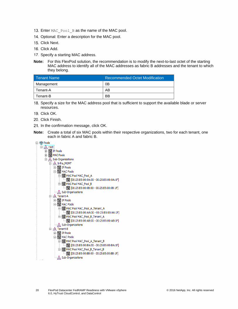
Enter MAC_Pool_B as the name of the MAC pool.
Optional: Enter a description for the MAC pool.
Click Next.
Click Add.
Specify a starting MAC address.
Note: For this FlexPod solution, the recommendation is to modify the next-to-last octet of the starting MAC address to identify all of the MAC addresses as fabric B addresses and the tenant to which they belong.
Tenant Name Recommended Octet Modification
Management 0B
Tenant-A AB
Tenant-B BB
Specify a size for the MAC address pool that is sufficient to support the available blade or server resources.
Click OK.
Click Finish.
In the confirmation message, click OK.
Note: Create a total of six MAC pools within their respective organizations, two for each tenant, one each in fabric A and fabric B.
Page 21
21 FlexPod Datacenter FedRAMP Readiness with VMware vSphere 6.0, HyTrust CloudControl, and DataControl
© 2016 NetApp, Inc. All rights reserved
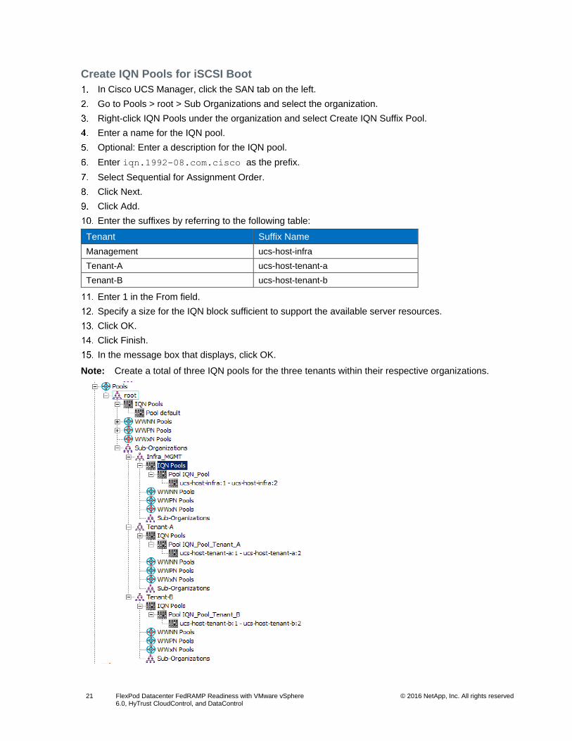
Create IQN Pools for iSCSI Boot
In Cisco UCS Manager, click the SAN tab on the left.
Go to Pools > root > Sub Organizations and select the organization.
Right-click IQN Pools under the organization and select Create IQN Suffix Pool.
Enter a name for the IQN pool.
Optional: Enter a description for the IQN pool.
Enter iqn.1992-08.com.cisco as the prefix.
Select Sequential for Assignment Order.
Click Next.
Click Add.
Enter the suffixes by referring to the following table:
Tenant Suffix Name
Management ucs-host-infra
Tenant-A ucs-host-tenant-a
Tenant-B ucs-host-tenant-b
Enter 1 in the From field.
Specify a size for the IQN block sufficient to support the available server resources.
Click OK.
Click Finish.
In the message box that displays, click OK.
Note: Create a total of three IQN pools for the three tenants within their respective organizations.
Page 22
22 FlexPod Datacenter FedRAMP Readiness with VMware vSphere 6.0, HyTrust CloudControl, and DataControl
© 2016 NetApp, Inc. All rights reserved
Create IP Pools for iSCSI Boot
In Cisco UCS Manager, click the LAN tab on the left.
Go to Pools > root > Sub Organizations and select the organization.
Note: Two IP pools are created per tenant, one for each switching fabric.
Right-click IP Pools under the tenant/organization and select Create IP Pool.
Enter a name for the IP pool for fabric A.
Optional: Enter a description of the IP pool.
Select Sequential for Assignment Order.
Click Next.
Click Add.
In the From field, enter the beginning of the range to assign as iSCSI IP addresses.
Note: In this deployment, the IP ranges for the iSCSI boot for each tenant and fabric are on a dedicated subnet and VLAN.
Set the size to enough addresses to accommodate the servers.
Click OK.
Click Finish.
Right-click IP Pools under the tenant/organization and select Create IP Pool.
Enter a for the name of the IP pool for fabric B.
Optional: Enter a description of the IP pool.
Select Sequential for Assignment Order.
Click Next.
Click Add.
In the From field, enter the beginning of the range to assign as iSCSI IP addresses.
Note: In this deployment, the IP ranges for the iSCSI boot for each tenant and fabric are on a dedicated subnet and VLAN.
Set the size to enough addresses to accommodate the servers.
Click OK.
Click Finish.
Note: Create a total of six iSCSI IP pools within their respective organizations, two for each tenant, one each in fabric A and fabric B.
Page 23
23 FlexPod Datacenter FedRAMP Readiness with VMware vSphere 6.0, HyTrust CloudControl, and DataControl
© 2016 NetApp, Inc. All rights reserved
Create UUID Suffix Pool
In Cisco UCS Manager, click the Servers tab in the navigation pane.
Go to Pools > root > Sub Organizations and select the organization.
Right-click UUID Suffix Pools and select Create UUID Suffix Pool.
Enter a name for the UUID suffix pool.
Optional: Enter a description for the UUID suffix pool.
Keep the prefix at the derived option.
Click Next.
Click Add to add a block of UUIDs.
Keep the From field at the default setting.
For this FlexPod solution, it is recommended to modify the fifth digit of the UUID to identify all the UUIDs based on their tenants.
Tenant Name UUID recommendation
Management 0000-0….
Tenant-A 0000-A….
Tenant-B 0000-B….
Specify a size for the UUID block that is sufficient to support the available blade or server resources.
Click OK.
Click Finish.
Page 24
24 FlexPod Datacenter FedRAMP Readiness with VMware vSphere 6.0, HyTrust CloudControl, and DataControl
© 2016 NetApp, Inc. All rights reserved
Click OK.
Note: Create a total of three UUID pools within their respective organizations.
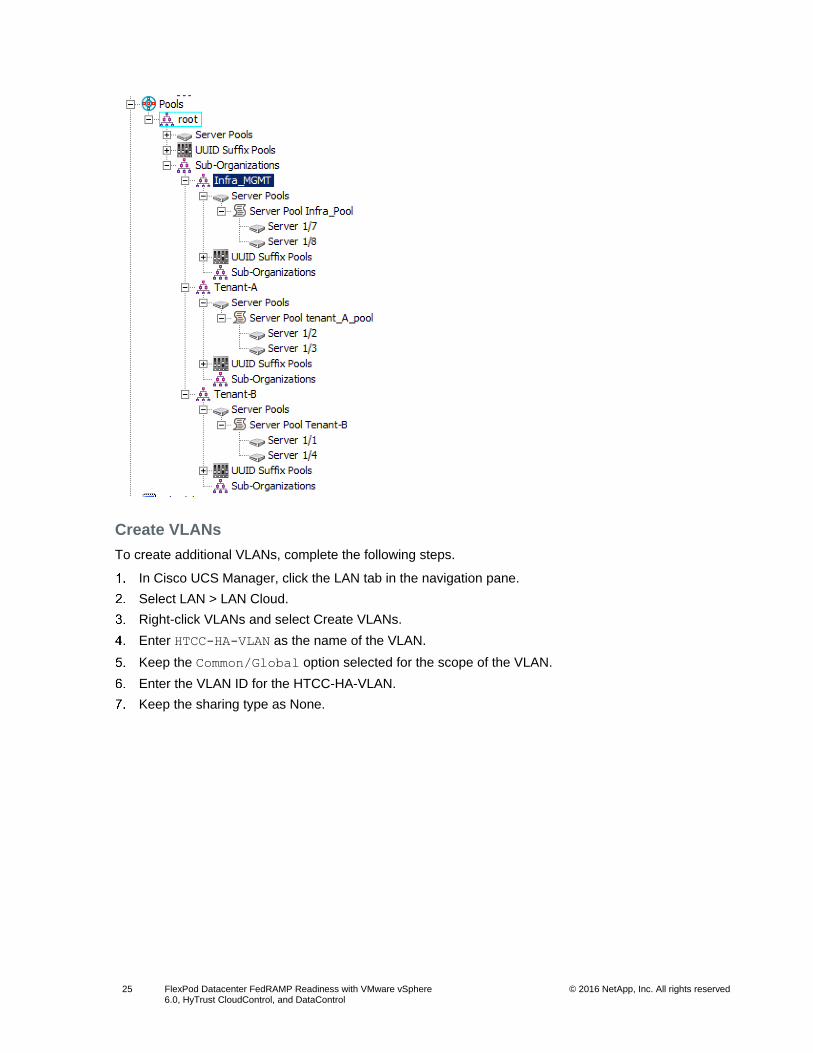
Create Server Pool
In Cisco UCS Manager, click the Servers tab in the navigation pane.
Go to Pools > root > Sub Organizations and select the organization.
Right-click Server Pools and select Create Server Pool.
Enter a name for the server pool.
Optional: Enter a description for the server pool.
Click Next.
Select two (or more) servers to be used for the cluster/tenant and click >> to add them to the server pool.
Note: Perform this step for the tenant A and tenant B clusters.
Click Finish.
Click OK.
Note: In total, three server pools need to be created for the three tenants within their respective organizations.
Page 25
25 FlexPod Datacenter FedRAMP Readiness with VMware vSphere 6.0, HyTrust CloudControl, and DataControl
© 2016 NetApp, Inc. All rights reserved
Create VLANs
To create additional VLANs, complete the following steps.
In Cisco UCS Manager, click the LAN tab in the navigation pane.
Select LAN > LAN Cloud.
Right-click VLANs and select Create VLANs.
Enter HTCC-HA-VLAN as the name of the VLAN.
Keep the Common/Global option selected for the scope of the VLAN.
Enter the VLAN ID for the HTCC-HA-VLAN.
Keep the sharing type as None.
Page 26
26 FlexPod Datacenter FedRAMP Readiness with VMware vSphere 6.0, HyTrust CloudControl, and DataControl
© 2016 NetApp, Inc. All rights reserved
Click OK and then click OK again.
Right-click VLANs and select Create VLANs.
Enter VM-Traffic-Tenant-A as the name of the VLAN.
Keep the Common/Global option selected for the scope of the VLAN.
Enter the VLAN ID for the VM-Traffic-Tenant-A VLAN.
Keep the Sharing Type as None.
Click OK and then click OK again.
Right-click VLANs and select Create VLANs.
Enter iSCSI-A-Tenant-A as the name of the VLAN.
Keep the Common/Global option selected for the scope of the VLAN.
Enter the VLAN ID for the iSCSI-A-Tenant-A VLAN.
Keep the Sharing Type as None.
Click OK and then click OK again.
Right-click VLANs and select Create VLANs.
Enter iSCSI-B-Tenant-A as the name of the VLAN.
Keep the Common/Global option selected for the scope of the VLAN.
Enter the VLAN ID for the iSCSI-B-Tenant-A VLAN.
Keep the Sharing Type as None.
Click OK and then click OK again.
Right-click VLANs and select Create VLANs.
Enter NFS-Tenant-A as the name of the VLAN.
Keep the Common/Global option selected for the scope of the VLAN.
Enter the VLAN ID for the NFS-Tenant-A VLAN.
Keep the Sharing Type as None.
Page 27
27 FlexPod Datacenter FedRAMP Readiness with VMware vSphere 6.0, HyTrust CloudControl, and DataControl
© 2016 NetApp, Inc. All rights reserved
Click OK and then click OK again.
Right-click VLANs and select Create VLANs.
Enter vMotion-Tenant-A as the name of the VLAN.
Keep the Common/Global option selected for the scope of the VLAN.
Enter the VLAN ID for the vMotion-Tenant-A VLAN.
Keep the Sharing Type as None.
Click OK and then click OK again.
Right-click VLANs and select Create VLANs.
Enter VM-Traffic-Tenant-B as the name of the VLAN.
Keep the Common/Global option selected for the scope of the VLAN.
Enter the VLAN ID for the VM-Traffic-Tenant-B VLAN.
Keep the Sharing Type as None.
Click OK and then click OK again.
Right-click VLANs and select Create VLANs.
Enter iSCSI-A-Tenant-B as the name of the VLAN.
Keep the Common/Global option selected for the scope of the VLAN.
Enter the VLAN ID for the iSCSI-A-Tenant-B VLAN.
Keep the Sharing Type as None.
Click OK and then click OK again.
Right-click VLANs and select Create VLANs.
Enter iSCSI-B-Tenant-B as the name of the VLAN.
Keep the Common/Global option selected for the scope of the VLAN.
Enter the VLAN ID for the iSCSI-B-Tenant-B VLAN.
Keep the Sharing Type as None.
Click OK and then click OK again.
Right-click VLANs and select Create VLANs.
Enter NFS-Tenant-B as the name of the VLAN.
Keep the Common/Global option selected for the scope of the VLAN.
Enter the VLAN ID for the NFS-Tenant-B VLAN.
Keep the Sharing Type as None.
Click OK and then click OK again.
Right-click VLANs and select Create VLANs.
Enter vMotion-Tenant-B as the name of the VLAN.
Keep the Common/Global option selected for the scope of the VLAN.
Enter the VLAN ID for the vMotion-Tenant-B VLAN.
Keep the Sharing Type as None.
Click OK and then click OK again.
Page 28
28 FlexPod Datacenter FedRAMP Readiness with VMware vSphere 6.0, HyTrust CloudControl, and DataControl
© 2016 NetApp, Inc. All rights reserved
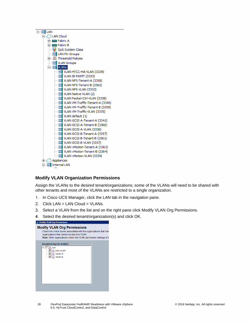
Modify VLAN Organization Permissions
Assign the VLANs to the desired tenant/organizations; some of the VLANs will need to be shared with
other tenants and most of the VLANs are restricted to a single organization.
In Cisco UCS Manager, click the LAN tab in the navigation pane.
Click LAN > LAN Cloud > VLANs.
Select a VLAN from the list and on the right pane click Modify VLAN Org Permissions.
Select the desired tenant/organization(s) and click OK.
Page 29
29 FlexPod Datacenter FedRAMP Readiness with VMware vSphere 6.0, HyTrust CloudControl, and DataControl
© 2016 NetApp, Inc. All rights reserved
Refer to the following table for the VLAN assignment.
VLAN Name Organization(s)
IB-MGMT Management, Tenant-A, Tenant-B
Native-VLAN Management, Tenant-A, Tenant-B
Packet-Ctrl-VLAN Management, Tenant-A, Tenant-B
HTCC-HA-VLAN Management
NFS-VLAN Management
VM-Traffic-VLAN Management
iSCSI-A-VLAN Management
iSCSI-B-VLAN Management
vMotion-VLAN Management
NFS-Tenant-A Tenant-A
VM-Traffic-Tenant-A Tenant-A
iSCSI-A-Tenant-A Tenant-A
iSCSI-B-Tenant-A Tenant-A
vMotion-Tenant-A Tenant-A
NFS-Tenant-B Tenant-B
VM-Traffic-Tenant-B Tenant-B
iSCSI-A-Tenant-B Tenant-B
iSCSI-B-Tenant-B Tenant-B
vMotion-Tenant-B Tenant-B
Create Host Firmware Package
Create a host firmware package within each of the three tenants by referring to the FlexPod Datacenter with Cisco UCS 6300 Fabric Interconnect and VMware vSphere 6.0 U1 CVD.
Create Local Disk Configuration Policy
Create a local disk configuration policy within each of the three tenants/organizations by referring to the CVD.
Page 30
30 FlexPod Datacenter FedRAMP Readiness with VMware vSphere 6.0, HyTrust CloudControl, and DataControl
© 2016 NetApp, Inc. All rights reserved
Create Network Control Policy for Cisco Discovery Protocol (CDP)
Create a network control policy within each of the three tenants/organizations by referring to the CVD.
Create Power Control Policy
Create a power control policy within each of the three tenants/organizations by referring to the CVD.
Page 31
31 FlexPod Datacenter FedRAMP Readiness with VMware vSphere 6.0, HyTrust CloudControl, and DataControl
© 2016 NetApp, Inc. All rights reserved
Create Server BIOS Policy
Create a server BIOS policy within each of the three tenants/organizations by referring to the CVD.
Create vNIC/vHBA Placement Policy for Virtual Machine Infrastructure Hosts
Create a vNIC/vHBA placement policy within each of the three tenants/organizations by referring to the CVD.
Update the Default Maintenance Policy
Update the Default Maintenance Policy for each of the three tenants/organizations by referring to the CVD.
Create vNIC Templates
Note: If vNIC templates are already created, you can modify the templates to match the configuration detailed in this section.
Create Data vNIC Templates
Note: Two data vNICs need to be created for each tenant, one in each fabric.
In Cisco UCS Manager, click the LAN tab in the navigation pane.
Go to Policies > root > Sub Organizations and select an organization.
Right-click vNIC Templates and select Create vNIC Template.
Page 32
32 FlexPod Datacenter FedRAMP Readiness with VMware vSphere 6.0, HyTrust CloudControl, and DataControl
© 2016 NetApp, Inc. All rights reserved
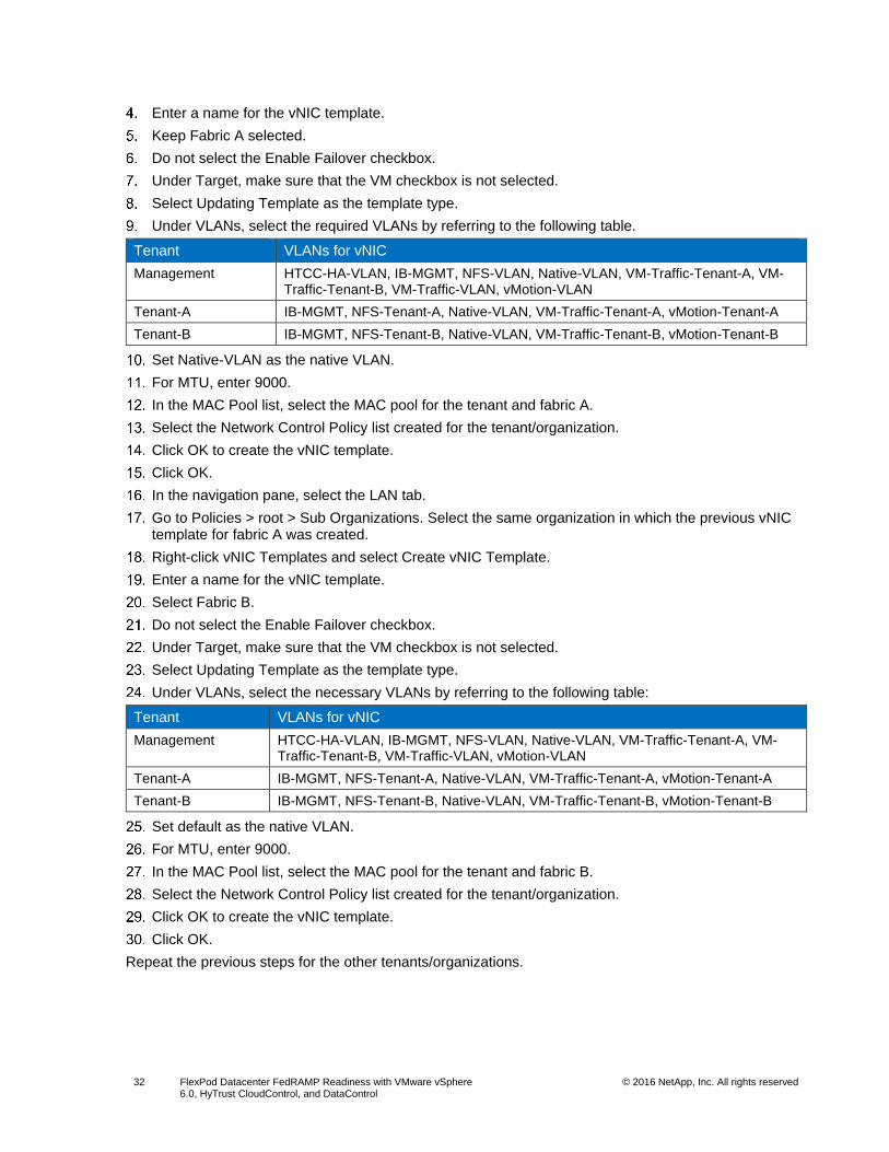
Enter a name for the vNIC template.
Keep Fabric A selected.
Do not select the Enable Failover checkbox.
Under Target, make sure that the VM checkbox is not selected.
Select Updating Template as the template type.
Under VLANs, select the required VLANs by referring to the following table.
Tenant VLANs for vNIC
Management HTCC-HA-VLAN, IB-MGMT, NFS-VLAN, Native-VLAN, VM-Traffic-Tenant-A, VM-Traffic-Tenant-B, VM-Traffic-VLAN, vMotion-VLAN
Tenant-A IB-MGMT, NFS-Tenant-A, Native-VLAN, VM-Traffic-Tenant-A, vMotion-Tenant-A
Tenant-B IB-MGMT, NFS-Tenant-B, Native-VLAN, VM-Traffic-Tenant-B, vMotion-Tenant-B
Set Native-VLAN as the native VLAN.
For MTU, enter 9000.
In the MAC Pool list, select the MAC pool for the tenant and fabric A.
Select the Network Control Policy list created for the tenant/organization.
Click OK to create the vNIC template.
Click OK.
In the navigation pane, select the LAN tab.
Go to Policies > root > Sub Organizations. Select the same organization in which the previous vNIC template for fabric A was created.
Right-click vNIC Templates and select Create vNIC Template.
Enter a name for the vNIC template.
Select Fabric B.
Do not select the Enable Failover checkbox.
Under Target, make sure that the VM checkbox is not selected.
Select Updating Template as the template type.
Under VLANs, select the necessary VLANs by referring to the following table:
Tenant VLANs for vNIC
Management HTCC-HA-VLAN, IB-MGMT, NFS-VLAN, Native-VLAN, VM-Traffic-Tenant-A, VM-Traffic-Tenant-B, VM-Traffic-VLAN, vMotion-VLAN
Tenant-A IB-MGMT, NFS-Tenant-A, Native-VLAN, VM-Traffic-Tenant-A, vMotion-Tenant-A
Tenant-B IB-MGMT, NFS-Tenant-B, Native-VLAN, VM-Traffic-Tenant-B, vMotion-Tenant-B
Set default as the native VLAN.
For MTU, enter 9000.
In the MAC Pool list, select the MAC pool for the tenant and fabric B.
Select the Network Control Policy list created for the tenant/organization.
Click OK to create the vNIC template.
Click OK.
Repeat the previous steps for the other tenants/organizations.
Page 33
33 FlexPod Datacenter FedRAMP Readiness with VMware vSphere 6.0, HyTrust CloudControl, and DataControl
© 2016 NetApp, Inc. All rights reserved
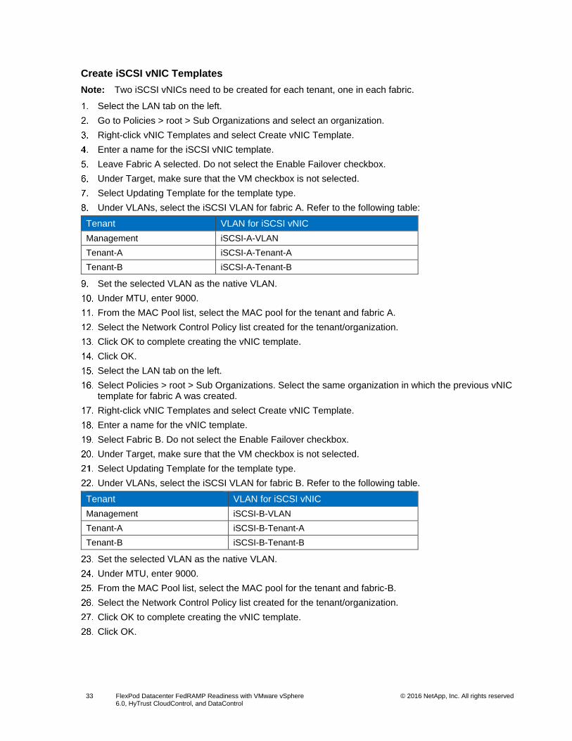
Create iSCSI vNIC Templates
Note: Two iSCSI vNICs need to be created for each tenant, one in each fabric.
Select the LAN tab on the left.
Go to Policies > root > Sub Organizations and select an organization.
Right-click vNIC Templates and select Create vNIC Template.
Enter a name for the iSCSI vNIC template.
Leave Fabric A selected. Do not select the Enable Failover checkbox.
Under Target, make sure that the VM checkbox is not selected.
Select Updating Template for the template type.
Under VLANs, select the iSCSI VLAN for fabric A. Refer to the following table:
Tenant VLAN for iSCSI vNIC
Management iSCSI-A-VLAN
Tenant-A iSCSI-A-Tenant-A
Tenant-B iSCSI-A-Tenant-B
Set the selected VLAN as the native VLAN.
Under MTU, enter 9000.
From the MAC Pool list, select the MAC pool for the tenant and fabric A.
Select the Network Control Policy list created for the tenant/organization.
Click OK to complete creating the vNIC template.
Click OK.
Select the LAN tab on the left.
Select Policies > root > Sub Organizations. Select the same organization in which the previous vNIC template for fabric A was created.
Right-click vNIC Templates and select Create vNIC Template.
Enter a name for the vNIC template.
Select Fabric B. Do not select the Enable Failover checkbox.
Under Target, make sure that the VM checkbox is not selected.
Select Updating Template for the template type.
Under VLANs, select the iSCSI VLAN for fabric B. Refer to the following table.
Tenant VLAN for iSCSI vNIC
Management iSCSI-B-VLAN
Tenant-A iSCSI-B-Tenant-A
Tenant-B iSCSI-B-Tenant-B
Set the selected VLAN as the native VLAN.
Under MTU, enter 9000.
From the MAC Pool list, select the MAC pool for the tenant and fabric-B.
Select the Network Control Policy list created for the tenant/organization.
Click OK to complete creating the vNIC template.
Click OK.
Page 34
34 FlexPod Datacenter FedRAMP Readiness with VMware vSphere 6.0, HyTrust CloudControl, and DataControl
© 2016 NetApp, Inc. All rights reserved
Create Boot Policies
Create a boot BIOS policy within each of the three tenants by referring to the CVD.
Create Service Profile Template
To create service profile templates for each tenant/organization, complete the following steps.
In Cisco UCS Manager, click the Servers tab in the navigation pane.
Go to Policies > root > Sub Organizations and select an organization.
Right-click the organization and select Create Service Profile Template.
Enter a name for the service profile template. The procedure described in the steps below configures the service profile template to boot from storage node 1 on fabric A.
Select the Updating Template option.
Under UUID, select the UUID pool created in the organization and click Next.
Configure Storage Provisioning
If there are servers with no physical disks, select the iSCSI-Boot local storage policy created in Organization. Otherwise, select the default Local Storage Policy.
Click Next.
Configure Networking Options
Keep the default setting for Dynamic vNIC Connection Policy.
Select the Expert option to configure the LAN connectivity.
Click the upper Add button to add a vNIC to the template.
In the Create vNIC dialog box, enter a name for the vNIC in fabric A.
Select the Use vNIC Template checkbox.
From the vNIC Template list, select the vNIC template created within the tenant/organization for fabric A.
From the Adapter Policy list, select VMWare.
Click OK to add this vNIC to the template.
On the Networking page of the wizard, click the upper Add button to add another vNIC to the template.
In the Create vNIC box, enter a name for the vNIC in fabric B.
Select the Use vNIC Template checkbox.
From the vNIC Template list, select the vNIC template created within the tenant/organization for fabric B.
From the Adapter Policy list, select VMWare.
Page 35
35 FlexPod Datacenter FedRAMP Readiness with VMware vSphere 6.0, HyTrust CloudControl, and DataControl
© 2016 NetApp, Inc. All rights reserved
Click OK to add the vNIC to the template.
Click the upper Add button to add a vNIC to the template.
In the Create vNIC dialog box, enter a name for the iSCSI vNIC in fabric A.
Select the Use vNIC Template checkbox.
From the vNIC Template list, select the iSCSI vNIC template created within the tenant/organization for fabric A.
From the Adapter Policy list, select VMWare.
Click OK to add this vNIC to the template.
Click the upper Add button to add a vNIC to the template.
In the Create vNIC dialog box, enter a name for the iSCSI vNIC in fabric B.
Select the Use vNIC Template checkbox.
From the vNIC Template list, select the iSCSI vNIC template created within the tenant/organization for fabric B.
From the Adapter Policy list, select VMWare.
Click OK to add this vNIC to the template.
Expand the iSCSI vNICs section (if not already expanded).
Select IQN-Pool under Initiator Name Assignment.
Click the lower Add button in the iSCSI vNIC section to define a vNIC.
Enter a name for the iSCSI vNIC in fabric A.
Select the iSCSI vNIC created in step 16 for fabric A as the overlay vNIC.
Set the iSCSI Adapter Policy to default.
Select the iSCSI-A VLAN created for the tenant/organization.
Leave the MAC Address set to None.
Click OK.
Click the lower Add button in the iSCSI vNIC section to define a vNIC.
Enter a name for the iSCSI vNIC in fabric B.
Select the iSCSI vNIC created in step 22 for fabric B as the overlay vNIC.
Set the iSCSI Adapter Policy to the default.
Select the iSCSI-B VLAN created for the tenant/organization.
Leave MAC Address set to None.
Click OK.
Click OK.
Review the table in the Networking page to make sure that all vNICs are created and click Next.
Configure Storage Options
Select the No vHBAs option for the How Would You Like to Configure SAN Connectivity? field.
Click Next.
Configure Zoning Options
Set no zoning options and click Next.
Page 36
36 FlexPod Datacenter FedRAMP Readiness with VMware vSphere 6.0, HyTrust CloudControl, and DataControl
© 2016 NetApp, Inc. All rights reserved
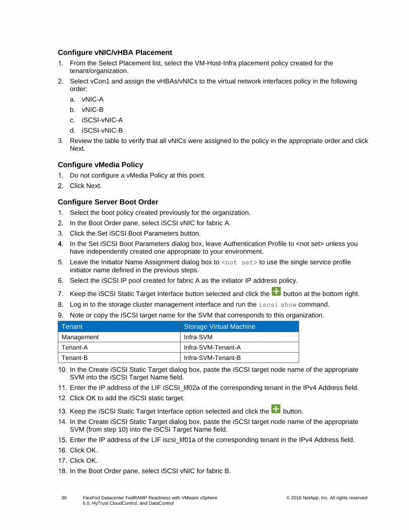
Configure vNIC/vHBA Placement
From the Select Placement list, select the VM-Host-Infra placement policy created for the tenant/organization.
Select vCon1 and assign the vHBAs/vNICs to the virtual network interfaces policy in the following order:
a. vNIC-A
b. vNIC-B
c. iSCSI-vNIC-A
d. iSCSI-vNIC-B
Review the table to verify that all vNICs were assigned to the policy in the appropriate order and click Next.
Configure vMedia Policy
Do not configure a vMedia Policy at this point.
Click Next.
Configure Server Boot Order
Select the boot policy created previously for the organization.
In the Boot Order pane, select iSCSI vNIC for fabric A.
Click the Set iSCSI Boot Parameters button.
In the Set iSCSI Boot Parameters dialog box, leave Authentication Profile to <not set> unless you have independently created one appropriate to your environment.
Leave the Initiator Name Assignment dialog box to <not set> to use the single service profile
initiator name defined in the previous steps.
Select the iSCSI IP pool created for fabric A as the initiator IP address policy.
Keep the iSCSI Static Target Interface button selected and click the button at the bottom right.
Log in to the storage cluster management interface and run the iscsi show command.
Note or copy the iSCSI target name for the SVM that corresponds to this organization.
Tenant Storage Virtual Machine
Management Infra-SVM
Tenant-A Infra-SVM-Tenant-A
Tenant-B Infra-SVM-Tenant-B
In the Create iSCSI Static Target dialog box, paste the iSCSI target node name of the appropriate SVM into the iSCSI Target Name field.
Enter the IP address of the LIF iSCSI_lif02a of the corresponding tenant in the IPv4 Address field.
Click OK to add the iSCSI static target.
Keep the iSCSI Static Target Interface option selected and click the button.
In the Create iSCSI Static Target dialog box, paste the iSCSI target node name of the appropriate SVM (from step 10) into the iSCSI Target Name field.
Enter the IP address of the LIF iscsi_lif01a of the corresponding tenant in the IPv4 Address field.
Click OK.
Click OK.
In the Boot Order pane, select iSCSI vNIC for fabric B.
Page 37
37 FlexPod Datacenter FedRAMP Readiness with VMware vSphere 6.0, HyTrust CloudControl, and DataControl
© 2016 NetApp, Inc. All rights reserved
Click the Set iSCSI Boot Parameters button.
In the Set iSCSI Boot Parameters dialog box, set Leave Initiator Name Assignment to <not set>.
Select the iSCSI IP Pool created for fabric B for the Initiator IP Address Policy.
Keep the iSCSI Static Target Interface option selected and click the button at the bottom right.
In the Create iSCSI Static Target window, paste the iSCSI target node name of the appropriate SVM (from step 10) into the iSCSI Target Name field.
Enter the IP address of the LIF iscsi_lif02b of the corresponding tenant for the IPv4 address field.
Click OK to add the iSCSI static target.
Keep the iSCSI Static Target Interface option selected and click the button.
In the Create iSCSI Static Target dialog box, paste the iSCSI target node name of the appropriate SVM (from step 10) into the iSCSI Target Name field
Enter the IP address of iscsi_lif01b in the IPv4 Address field.
Click OK.
Click OK.
Review the table to make sure that all boot devices were created and identified. Verify that the boot devices are in the correct boot sequence.
Click Next to continue to the next section.
Configure Maintenance Policy
Leave the default maintenance policy of the organization/tenant selected.
Click Next.
Configure Server Assignment
From the Pool Assignment list, select the server pool created for the organization.
Optional: Select a server pool qualification policy.
Select Down as the power state to be applied when the profile is associated with the server.
Expand Firmware Management at the bottom of the page and select default from the Host Firmware list.
Click Next.
Configure Operational Policies
Select the BIOS policy created for the organization.
Expand Power Control Policy Configuration and select the power control policy created for the organization.
Click Finish to create the service profile template.
Click OK in the confirmation message.
Note: At least three service profile templates need to be created, one for each tenant/organization.
Note: An extra boot policy to boot from fabric B can also be created within each tenant/organization.
Create Service Profiles
In Cisco UCS Manager, click the Servers tab in the navigation pane.
Select Service Profile Templates > root > Sub-Organization. Select a service profile template.
Right-click the service profile template and select Create Service Profiles from Template.
Enter a prefix for the service profile.
Page 38
38 FlexPod Datacenter FedRAMP Readiness with VMware vSphere 6.0, HyTrust CloudControl, and DataControl
© 2016 NetApp, Inc. All rights reserved
Enter a numerical value as Name Suffix Starting Number.
Enter the number of instances of service profiles to be deployed.
Click OK to create the service profile(s).
Click OK in the confirmation message.
Note: Service Profiles need to be deployed within each organization using the service profile templates created within each organization.
Gather Necessary Information
After the Cisco UCS service profiles have been created, each infrastructure blade in the environment will
have a unique configuration. To proceed with the FlexPod deployment, specific information must be
gathered from each Cisco UCS blade and from the NetApp controllers. Insert the required information into
Error! Reference source not found. and Table 4.
Table 3) iSCSI LIFs for iSCSI IQN.
Vserver Target: WWPN (FC) or IQN (iSCSI)
Infra-SVM
Infra-SVM-Tenant-A
Infra-SVM-Tenant-B
Note: To obtain the iSCSI IQN, run the iscsi show command on the storage cluster management interface.
Table 4) vNIC iSCSI IQNs for fabric A and fabric B.
Cisco UCS Service Profile Name Initiator: IQN (iSCSI) Variables
VM-Host-Infra-01 <<var_vm_host_infra_01_iqn>>
VM-Host-Infra-02 <<var_vm_host_infra_02_iqn>>
VM-Host-Infra-Tenant-A-01 <<var_vm_host_infra_tenant_a_01_iqn>>
VM-Host-Infra-Tenant-A-02 <<var_vm_host_infra_tenant_a_02_iqn>>
VM-Host-Infra-Tenant-B-01 <<var_vm_host_infra_tenant_b_01_iqn>>
VM-Host-Infra-Tenant-B-02 <<var_vm_host_infra_tenant_b_02_iqn>>
Note: To obtain the iSCSI vNIC IQN information in the Cisco UCS Manager GUI, go to Servers > Service Profiles > root. Click each service profile and then click the iSCSI vNICs tab on the right. The initiator name is displayed at the top of the page under Service Profile Initiator Name.
5.4 NetApp Storage Configuration—Part II
iSCSI Boot Configuration
Create igroups for LUN mapping.
igroup create –vserver Infra-SVM-MGMT –igroup VM-Host-Infra-01 –protocol iscsi –ostype vmware –
initiator <<var_vm_host_infra_01_iqn>>
igroup create –vserver Infra-SVM-MGMT –igroup VM-Host-Infra-02 –protocol iscsi –ostype vmware –
initiator <<var_vm_host_infra_02_iqn>>
igroup create –vserver Infra-SVM-Tenant-A –igroup VM-Host-Infra-01_tenant_A –protocol iscsi –
ostype vmware –initiator <<var_vm_host_infra_01_iqn_tenant_A>>
igroup create –vserver Infra-SVM-Tenant-A –igroup VM-Host-Infra-02_tenant_A –protocol iscsi –
Page 39
39 FlexPod Datacenter FedRAMP Readiness with VMware vSphere 6.0, HyTrust CloudControl, and DataControl
© 2016 NetApp, Inc. All rights reserved
ostype vmware –initiator <<var_vm_host_infra_02_iqn_tenant_A>>
igroup create –vserver Infra-SVM-Tenant-B –igroup VM-Host-Infra-01_tenant_B –protocol iscsi –
ostype vmware –initiator <<var_vm_host_infra_01_iqn_tenant_B>>
igroup create –vserver Infra-SVM-Tenant-B –igroup VM-Host-Infra-02_tenant_B –protocol iscsi –
ostype vmware –initiator <<var_vm_host_infra_02_iqn_tenant_B>>
Note: The initiator IQNs are available in Table 2.
Map boot LUNs to hosts.
lun map –vserver Infra-SVM-MGMT –volume esxi_boot –lun VM-Host-Infra-01 –igroup VM-Host-Infra-01
–lun-id 0
lun map –vserver Infra-SVM-MGMT –volume esxi_boot –lun VM-Host-Infra-02 –igroup VM-Host-Infra-02
–lun-id 0
lun map –vserver Infra-SVM-Tenant-A –volume esxi_boot –lun VM-Host-Infra-01_tenant_A –igroup VM-
Host-Infra-01_tenant_A –lun-id 0
lun map –vserver Infra-SVM-Tenant-A –volume esxi_boot –lun VM-Host-Infra-02_tenant_A –igroup VM-
Host-Infra-02_tenant_A –lun-id 0
lun map –vserver Infra-SVM-Tenant-B –volume esxi_boot –lun VM-Host-Infra-01_tenant_B –igroup VM-
Host-Infra-01_tenant_B –lun-id 0
lun map –vserver Infra-SVM-Tenant-B –volume esxi_boot –lun VM-Host-Infra-02_tenant_B –igroup VM-
Host-Infra-02_tenant_B –lun-id 0
5.5 VMware vSphere 6.0 Setup
In this deployment, a total of six ESXi hosts were deployed and were added to three clusters:
management, tenant A, and tenant B. Each cluster was allocated two ESXi servers and each cluster
represents a tenant.
Tenant ESXi Hosts
Management esxi01-patriots.cie.netapp.com
esxi02-patriots.cie.netapp.com
Tenant-A esxi03-patriots.cie.netapp.com
esxi04-patriots.cie.netapp.com
Tenant-B esxi05-patriots.cie.netapp.com
esxi06-patriots.cie.netapp.com
Follow the procedures as described in the CVD to install ESXi 6.0 on the Cisco UCS blades. Additional
configurations that are required for various sections are described in the sections that follow. For all
sections not listed below, repeat the procedure as described in the CVD for all the ESXi hosts.
Set Up VMkernel Ports and Virtual Switches
You must create the necessary VMkernel ports and vSwitches for the ESXi servers within each tenant.
Table 5 lists the VMkernel ports that need to be created in the ESXi hosts for each tenant using the
corresponding VLAN IDs.
Table 5) VMKernel ports.
Tenant VMkernel and vSwitch Details
Management vSwitch0 iScsiBootvSwitch vSwitch1
VMkernel-MGMT
VMkernel-NFS
VMkernel-vMotion
VMkernel-HTCC-HA
VMkernel-VMTraffic
VMkernel-iSCSI-A VMkernel-iSCSI-B
Page 40
40 FlexPod Datacenter FedRAMP Readiness with VMware vSphere 6.0, HyTrust CloudControl, and DataControl
© 2016 NetApp, Inc. All rights reserved
Tenant VMkernel and vSwitch Details
VMkernel-VMTraffic-Tenant-A
VMkernel-VMTraffic-Tenant-B
Tenant-A VMkernel-MGMT
VMkernel-NFS-Tenant-A
VMkernel-vMotion-Tenant-A
VMkernel-VMTraffic-Tenant-A
VMkernel-iSCSI-A-Tenant-A
VMkernel-iSCSI-B-Tenant-A
Tenant-B VMkernel-MGMT
VMkernel-NFS-Tenant-B
VMkernel-vMotion-Tenant-B
VMkernel-VMTraffic-Tenant-B
VMkernel-iSCSI-A-Tenant-B
VMkernel-iSCSI-B-Tenant-B
The following procedure describes the addition of an HTCC VMkernel port to vSwitch0 of an ESXi host
that will be placed in the management cluster later.
From the Home menu of vSphere Web Client, select Hosts and Clusters under the Inventories section.
Select an ESXi host from the list and click the Manage tab.
Click the Networking tab and select VMkernel Adapters.
Click the first icon to add host networking.
Select VMkernel Network Adapter and click Next.
Click the Select an Existing Network button and click Browse.
Select the HTCC-HA-VLAN from the list and click OK. Click Next.
Use the default network label and click Next.
Page 41
41 FlexPod Datacenter FedRAMP Readiness with VMware vSphere 6.0, HyTrust CloudControl, and DataControl
© 2016 NetApp, Inc. All rights reserved
Select Use Static IPv4 Settings Automatically. Enter the IP address and the subnet mask for the HTCC-HA-VLAN interface for the selected host.
Review the settings and click Finish.
A new VMkernel adapter is created for the HTCC-HA-VLAN network.
Page 42
42 FlexPod Datacenter FedRAMP Readiness with VMware vSphere 6.0, HyTrust CloudControl, and DataControl
© 2016 NetApp, Inc. All rights reserved
Repeat steps 2 to 11 for the remaining ESXi hosts that need to be placed in the management cluster.
Note: The HTCC-HA-VLAN is required in the management cluster only to host HyTrust CloudControl.
Complete the previous steps to create the VMkernel ports for all the ESXi servers across all
clusters/tenants.
Set Up iSCSI Multipathing
To set up iSCSI multipathing, complete the following steps:
Follow the steps to set up iSCSI multipathing as described in the CVD.
When providing the iSCSI LIF IP addresses for Dynamic Discovery, make sure to provide the LIF IPs belonging to the appropriate tenant.
Mount Required Datastores
Using the procedure described in the CVD, mount the following listed datastores/volumes to the ESXi hosts.
ESXi Hosts Datastores/ Volumes
esxi01-patriots.cie.netapp.com
esxi02-patriots.cie.netapp.com
Infra_datastore_1
Infra_swap
esxi03-patriots.cie.netapp.com
esxi04-patriots.cie.netapp.com
Infra_datastore_1_tenant_A
Infra_swap_tenant_A
esxi05-patriots.cie.netapp.com
esxi06-patriots.cie.netapp.com
Infra_datastore_1_tenant_B
Infra_swap_tenant_B
Note: When mounting the datastores, make sure to provide the NFS LIF IP from the corresponding tenant.
Move VM Swap File Location
Using the procedures described in the CVD, store the VM Swap File on the infra_swap datastore
mounted on each ESXi.
Page 43
43 FlexPod Datacenter FedRAMP Readiness with VMware vSphere 6.0, HyTrust CloudControl, and DataControl
© 2016 NetApp, Inc. All rights reserved
VMware vCenter 6.0
Follow the procedures described in the CVD to deploy the vCenter Server Appliance. The vCenter Server
Appliance will need to be deployed on an ESXi host that will eventually be part of the management
cluster.
Create Clusters and Add Hosts
Using the procedures described in the CVD, create additional clusters for the tenants within the same
FlexPod_DC data center.
After the clusters are created, add the ESXi hosts to them. The cluster-to-ESXi server association is as
follows:
Cluster ESXi Hosts
Management esxi01-patriots.cie.netapp.com
esxi02-patriots.cie.netapp.com
Tenant-A esxi03-patriots.cie.netapp.com
esxi04-patriots.cie.netapp.com
Tenant-B esxi05-patriots.cie.netapp.com
esxi06-patriots.cie.netapp.com
5.6 Cisco Nexus 1000v VSM Configuration
Register Cisco Nexus 1000v with vCenter
Cisco Nexus 1000v can be registered to the vCenter server using the Virtual Switch Update Manager or
by manually registering the 1000v using the PowerShell script available at http://VSM-IP-
Address/vcplugin/registerVCPlugin.ps1.
Update the Primary VSM
This step assumes that the base configuration of the Cisco Nexus 1110-X and the primary and secondary
VSM is completed as described in the CVD.
Using an SSH client, log in to the primary Cisco Nexus 1000V VSM as admin and run the following commands:
config t
vlan <<var_htcc_ha_vlan_id>>
name HTCC-HA-VLAN
exit
vlan <<var_vm_traffic_vlan_tenant_a>>
name VM-Traffic-VLAN-Tenant-A
exit
vlan <<var_iscsi_a_vlan_tenant_a>>
name iSCSI-A-VLAN-Tenant-A
exit
vlan <<var_iscsi_b_vlan_tenant_a>>
name iSCSI-B-VLAN-Tenant-A
exit
vlan <<var_nfs_vlan_tenant_a>>
name NFS-VLAN-Tenant-A
exit
vlan <<var_vmotion_vlan_tenant_a>>
name vMotion-VLAN-Tenant-A
exit
vlan <<var_vm_traffic_vlan_tenant_b>>
name VM-Traffic-VLAN-Tenant-B
exit
vlan <<var_iscsi_a_vlan_tenant_b>>
Page 44
44 FlexPod Datacenter FedRAMP Readiness with VMware vSphere 6.0, HyTrust CloudControl, and DataControl
© 2016 NetApp, Inc. All rights reserved
name iSCSI-A-VLAN-Tenant-B
exit
vlan <<var_iscsi_b_vlan_tenant_b>>
name iSCSI-B-VLAN-Tenant-B
exit
vlan <<var_nfs_vlan_tenant_b>>
name NFS-VLAN-Tenant-B
exit
vlan <<var_vmotion_vlan_tenant_b>>
name vMotion-VLAN-Tenant-B
exit
port-profile type ethernet system-uplink
switchport trunk allowed vlan add <<var_htcc_ha_vlan_id>>
no shutdown
system vlan <<var_ib-mgmt_vlan_id>>
state enabled
port-profile type ethernet system-uplink-tenant-a
vmware port-group
switchport mode trunk
switchport trunk native vlan <<var_native_vlan_id>>
switchport trunk allowed vlan <<var_ib-mgmt_vlan_id>>, <<var_nfs_vlan_tenant_a>>,
<<var_vmotion_vlan_tenant_a>>, <<var_vm-traffic_vlan_tenant_a>>
channel-group auto mode on mac-pinning
no shutdown
system vlan <<var_ib-mgmt_vlan_id>>
system mtu 9000
state enabled
port-profile type ethernet system-uplink-tenant-b
vmware port-group
switchport mode trunk
switchport trunk native vlan <<var_native_vlan_id>>
switchport trunk allowed vlan <<var_ib-mgmt_vlan_id>>, <<var_nfs_vlan_tenant_b>>,
<<var_vmotion_vlan_tenant_b>>, <<var_vm-traffic_vlan_tenant_b>>
channel-group auto mode on mac-pinning
no shutdown
system vlan <<var_ib-mgmt_vlan_id>>
system mtu 9000
state enabled
port-profile type ethernet iscsi-a-uplink-tenant-a
vmware port-group
switchport mode trunk
switchport trunk native vlan <<var_iscsi_a_vlan_tenant_a>>
switchport trunk allowed vlan <<var_iscsi_a_vlan_tenant_a>>
no shutdown
system vlan <<var_iscsi_a_vlan_tenant_a>>
system mtu 9000
state enabled
port-profile type ethernet iscsi-b-uplink-tenant-a
vmware port-group
switchport mode trunk
switchport trunk native vlan <<var_iscsi_b_vlan_tenant_a>>
switchport trunk allowed vlan <<var_iscsi_b_vlan_tenant_a>>
no shutdown
system vlan <<var_iscsi_b_vlan_tenant_a>>
system mtu 9000
state enabled
port-profile type ethernet iscsi-a-uplink-tenant-b
vmware port-group
switchport mode trunk
switchport trunk native vlan <<var_iscsi_a_vlan_tenant_b>>
switchport trunk allowed vlan <<var_iscsi_a_vlan_tenant_b>>
no shutdown
system vlan <<var_iscsi_a_vlan_tenant_b>>
system mtu 9000
state enabled
Page 45
45 FlexPod Datacenter FedRAMP Readiness with VMware vSphere 6.0, HyTrust CloudControl, and DataControl
© 2016 NetApp, Inc. All rights reserved
port-profile type ethernet iscsi-b-uplink-tenant-b
vmware port-group
switchport mode trunk
switchport trunk native vlan <<var_iscsi_b_vlan_tenant_b>>
switchport trunk allowed vlan <<var_iscsi_b_vlan_tenant_b>>
no shutdown
system vlan <<var_iscsi_b_vlan_tenant_b>>
system mtu 9000
state enabled
port-profile type vethernet HTCC-HA-VLAN
vmware port-group
switchport mode access
switchport access vlan <<var_htcc_ha_vlan_id>>
no shutdown
system vlan <<var_htcc_ha_vlan_id>>
state enabled
exit
port-profile type vethernet NFS-VLAN-tenant-a
vmware port-group
switchport mode access
switchport access vlan <<var_nfs_vlan_tenant_a>>
no shutdown
system vlan <<var_nfs_vlan_tenant_a>>
state enabled
port-profile type vethernet vMotion-VLAN-tenant-a
vmware port-group
switchport mode access
switchport access vlan <<var_vmotion_vlan_tenant_a>>
no shutdown
system vlan <<var_vmotion_vlan_tenant_a>>
state enabled
port-profile type vethernet VM-Traffic-VLAN-tenant-a
vmware port-group
switchport mode access
switchport access vlan <<var_vm-traffic_vlan_tenant_a>>
no shutdown
system vlan <<var_vm-traffic_vlan_tenant_a>>
state enabled
port-profile type vethernet iSCSI-A-VLAN-tenant-a
vmware port-group
switchport mode access
switchport access vlan <<var_iscsi_a_vlan_tenant_a>>
no shutdown
system vlan <<var_iscsi_a_vlan_tenant_a>>
state enabled
port-profile type vethernet iSCSI-B-VLAN-tenant-a
vmware port-group
switchport mode access
switchport access vlan <<var_iscsi_b_vlan_tenant_a>>
no shutdown
system vlan <<var_iscsi_b_vlan_tenant_a>>
state enabled
port-profile type vethernet NFS-VLAN-tenant-b
vmware port-group
switchport mode access
switchport access vlan <<var_nfs_vlan_tenant_b>>
no shutdown
system vlan <<var_nfs_vlan_tenant_b>>
state enabled
port-profile type vethernet vMotion-VLAN-tenant-b
vmware port-group
switchport mode access
Page 46
46 FlexPod Datacenter FedRAMP Readiness with VMware vSphere 6.0, HyTrust CloudControl, and DataControl
© 2016 NetApp, Inc. All rights reserved
switchport access vlan <<var_vmotion_vlan_tenant_b>>
no shutdown
system vlan <<var_vmotion_vlan_tenant_b>>
state enabled
port-profile type vethernet VM-Traffic-VLAN-tenant-b
vmware port-group
switchport mode access
switchport access vlan <<var_vm-traffic_vlan_tenant_b>>
no shutdown
system vlan <<var_vm-traffic_vlan_tenant_b>>
state enabled
port-profile type vethernet iSCSI-A-VLAN-tenant-b
vmware port-group
switchport mode access
switchport access vlan <<var_iscsi_a_vlan_tenant_b>>
no shutdown
system vlan <<var_iscsi_a_vlan_tenant_b>>
state enabled
port-profile type vethernet iSCSI-B-VLAN-tenant-b
vmware port-group
switchport mode access
switchport access vlan <<var_iscsi_b_vlan_tenant_b>>
no shutdown
system vlan <<var_iscsi_b_vlan_tenant_b>>
state enabled
exit
copy run start
Add VMware ESXi Hosts to Cisco Nexus 1000v
The ESXi hosts can be added to the 1000v using the Virtual Switch Update Manager as described in the
CVD. These hosts can also be added by manually installing the Cisco Nexus 1000v VEM on each ESXi
by downloading it from http://VSM-IP-Address/cross_cisco-vem-v199-5.2.1.3.1.5b.0-6.0.1.vib.
5.7 HyTrust CloudControl Installation and Configuration
HyTrust CloudControl (HTCC) offers system managers and administrators an end-to-end virtualization
security platform to manage access, standardize and control configuration, and protect a virtual
infrastructure within a customer's environment.
Network Architecture and Topology
HyTrust CloudControl can be deployed in two network configurations: Mapped Mode or Router Mode.
In Mapped Mode, HTCC works as a proxy server and does not require making any architectural changes
to the virtual infrastructure network.
In Router Mode, HTCC joins two IPv4 networks, passing information from one network to the other. This
mode also requires changes to the existing routing infrastructure.
In this deployment, HTCC will be installed in a HA configuration in Mapped Mode. To facilitate the HA
configuration, HTCC requires a dedicated private network between the two HTCC instances. The HTCC
HA VLAN is used for this purpose.
Page 47
47 FlexPod Datacenter FedRAMP Readiness with VMware vSphere 6.0, HyTrust CloudControl, and DataControl
© 2016 NetApp, Inc. All rights reserved
Install HyTrust CloudControl in High-Availability Configuration
The HyTrust CloudControl will be installed in the management cluster within the VMware environment.
Obtaining the Software
Log in to the HyTrust website or follow the directions you received from HyTrust Support to obtain the download URL of the HTCC OVF file.
Install Primary HTCC Appliance
From the Home menu in vSphere Web Client, select VMs and Templates under the Inventories section.
Right-click the FlexPod_DC data center or VM Folder and select Deploy OVF Template.
Click Allow.
Browse to the OVF file of the HyTrust CloudControl appliance and click Open.
Click Next.
Review the OVF template details and click Next.
Accept the license agreement and click Next.
Enter a name for the HTCC primary appliance and select a folder or data center where it should reside.
Page 48
48 FlexPod Datacenter FedRAMP Readiness with VMware vSphere 6.0, HyTrust CloudControl, and DataControl
© 2016 NetApp, Inc. All rights reserved
Click Next.
Select the FlexPod_Management cluster and click Next.
Select infra_datastore_1 as the storage and click Next.
Assign the Appliance NICs as follows:
a. HTCC Primary NIC (eth0) IB-MGMT-VLAN
b. HTCC Secondary NIC (eth1) Unused_Or_Quarantine_Veth
c. HTCC Tertiary NIC (eth2) HTCC-HA-VLAN
Click Next.
Review the settings and click Finish.
Wait for the OVF template to be deployed.
Select the HTCC primary virtual machine from the Inventory pane and from the Summary tab click Launch Remote Console.
Page 49
49 FlexPod Datacenter FedRAMP Readiness with VMware vSphere 6.0, HyTrust CloudControl, and DataControl
© 2016 NetApp, Inc. All rights reserved
Click Launch Application if prompted.
Click the green button (second from left) to power on the VM.
Configure Primary HTCC Management Network Interface
In the console window of the HTCC VM, log in as ascadminuser with the password
Pa$$w0rd123!.
Enter the current password, Pa$$w0rd123!.
Assign a new password for the ascadminuser and reenter the password to confirm.
Start the setup procedure by running the setup command.
Enter n when asked to configure a virtual management IP address.
Enter the IPv4 address for the management network connection (eth0) interface,
<<var_htcc_pri_mgmt_ip>>.
Enter the netmask <<var_htcc_pri_netmask>>.
Enter the gateway <<var_htcc_pri_gw>>.
Enter the DNS server IP addresses.
Review the network settings and confirm.
Log out after the network settings are updated.
Open a web browser and navigate to https://<<var_htcc_pri_mgmt_ip>>/asc.
Note: FQDN is not supported until the installation wizard completes.
Note: Use the IPv4 address.
Note: NetApp recommends using Mozilla Firefox as the browser.
Allow the security exceptions if prompted.
Log in using the default user name superadminuser and password Pa$$w0rd123!.
Accept the license agreement and click Next.
Upload the license file with the .xml extension and click Next.
In the Network Configuration page, assign a host name for the HTCC primary appliance and review the network settings.
Update the (comma separated) list of DNS servers if necessary.
Note: Provide only IP addresses for DNS servers.
Select the Enable NTP Servers checkbox and enter the NTP server IP addresses (comma separated).
Note: Provide only IP addresses for NTP servers.
Click Next.
Click Finish to complete the installation wizard.
Note: The Finish button is not enabled until the Installation wizard completes.
Upon successful installation, the HTCC Management Console Appliance Dashboard appears.
Page 50
50 FlexPod Datacenter FedRAMP Readiness with VMware vSphere 6.0, HyTrust CloudControl, and DataControl
© 2016 NetApp, Inc. All rights reserved
From the vSphere Web Client, connect to the console of the HTCC primary virtual machine.
Log in as ascadminuser.
Start the HA setup procedure by running the hasetup command.
At the Please specify network settings for the Connection 1 (eth0) interface
prompt, confirm the settings assigned to the primary HTCC. Enter n to skip reconfiguring the network
settings.
At the Deploy as primary (production) or secondary (standby) (pri/sec) prompt,
type pri.
Enter y to configure a private network for high availability.
At the Please specify network settings for High Availability services on
Connection 3 (eth2) interface prompt, enter the primary HTCC connection 3 (eth2) details.
Note: The <<var_htcc_pri_ha_ip>> and <<var_htcc_pri_ha_netmask>> network parameters defined for the HTCC-HA-VLAN need to be used.
Enter y when prompted to save the settings.
Enter n when asked to configure a virtual management IP address.
The HA setup for primary HTCC is now complete. Next, you must install and configure a second HTCC
instance and join the two HTCCs to create an HTCC-HA cluster.
Install Secondary HTCC Appliance
From the Home menu in the vSphere Web Client, select VMs and Templates under the Inventories section.
Right-click the FlexPod_DC data center or the VM folder and select Deploy OVF Template.
Click Allow.
Browse to the OVF file of the HyTrust CloudControl appliance and click Open.
Click Next.
Page 51
51 FlexPod Datacenter FedRAMP Readiness with VMware vSphere 6.0, HyTrust CloudControl, and DataControl
© 2016 NetApp, Inc. All rights reserved
Review the OVF template details and click Next.
Accept the license agreement and click Next.
Enter a name for the HTCC secondary appliance and select a folder or data center where it should reside.
Click Next.
Select the FlexPod_Management cluster and click Next.
Select infra_datastore_1 as the storage and click Next.
Assign the appliance NICs as follows:
a. HTCC Primary NIC (eth0) IB-MGMT-VLAN
b. HTCC Secondary NIC (eth1) Unused_Or_Quarantine_Veth
c. HTCC Tertiary NIC (eth2) HTCC-HA-VLAN
Page 52
52 FlexPod Datacenter FedRAMP Readiness with VMware vSphere 6.0, HyTrust CloudControl, and DataControl
© 2016 NetApp, Inc. All rights reserved
Click Next.
Review the settings and click Finish.
Wait for the OVF template to be deployed.
Select the HTCC secondary virtual machine from the Inventory pane and from the Summary tab click Launch Remote Console.
Click Launch Application if prompted.
Click the green button (second from left) to power on the VM.
Configure Secondary HTCC Management Network Interface
In the console window of the HTCC VM, log in as ascadminuser with the password
Pa$$w0rd123!.
Enter the current password Pa$$w0rd123!.
Assign a new password for the ascadminuser and reenter the password to confirm.
Start the setup procedure by running the setup command.
Enter n when asked to configure a virtual management IP address.
Enter the IPv4 address for the management network connection (eth0) interface, <<
var_htcc_sec_ip >>.
Enter the netmask <<var_htcc_sec_netmask>>.
Enter the gateway <<var_htcc_sec_gw>>.
Enter the DNS server IP addresses.
Review the network settings and confirm.
Log out after the network settings have been updated.
Open a web browser and navigate to https://<<var_htcc_sec_ip>>/asc.
Note: FQDN is not supported until the installation wizard completes.
Note: Use IPv4 address.
Note: NetApp recommends using Mozilla Firefox as the browser.
Allow the security exceptions if prompted.
Page 53
53 FlexPod Datacenter FedRAMP Readiness with VMware vSphere 6.0, HyTrust CloudControl, and DataControl
© 2016 NetApp, Inc. All rights reserved
Log in using the default user name superadminuser and the password Pa$$w0rd123!.
Accept the license agreement and click Next.
Upload the license file with the .xml extension and click Next.
In the Network Configuration page, assign a host name for the HTCC secondary appliance and review the network settings.
Update the list of (comma separated) DNS servers if necessary.
Note: Provide only IP addresses for DNS servers.
Click the Enable NTP Servers checkbox and enter the NTP server IP addresses (comma separated).
Note: Provide only IP addresses for NTP servers.
Click Next.
Click Finish to complete the installation wizard.
Note: The Finish button is not enabled until the installation wizard completes.
The HTCC Management Console Appliance Dashboard appears on successful installation.
From the vSphere Web Client, connect to the console of the HTCC secondary virtual machine.
Log in as ascadminuser.
Start the HA setup procedure by running the hasetup command.
At the Please specify network settings for the Connection 1 (eth0) interface
prompt, confirm the settings assigned to the secondary HTCC. Enter n to skip reconfiguring the
network settings.
At the Deploy as primary (production) or secondary (standby) (pri/sec) prompt,
type sec.
Enter y to configure a private network for high availability.
Page 54
54 FlexPod Datacenter FedRAMP Readiness with VMware vSphere 6.0, HyTrust CloudControl, and DataControl
© 2016 NetApp, Inc. All rights reserved
At the Please specify network settings for High Availability services on
Connection 3 (eth2) interface prompt, enter the secondary HTCC Connection 3 (eth2)
details.
Note: The <var_htcc_pri_ha_ip>> network parameter defined for the HTCC-HA-VLAN should be used.
Note: This process might take several minutes as the secondary HTCC establishes communication with the primary HTCC.
After this process completes, the secondary HTCC updates and displays the HyTrust high-availability
(HA) system status as Enabled and the mode as Secondary. The HA status is also updated on the
primary HTCC and shows the mode as Primary after the CLI command window is refreshed.
Configure HTCC to Directory Service Mode
Configure HyTrust CloudControl to perform authentication against a Microsoft Active Directory service for
a streamlined access policy to the HTCC appliance.
Create a Service Account
Log in to the Windows machine running the Active Directory server using credentials that have sufficient privileges to create accounts.
In Active Directory, add a new user to serve as the HTCC service account.
Full name: HtaServiceAccount
User login name: htaserviceaccount
Create Security Groups
The default HTCC rules are created by mapping existing user groups in Active Directory to default roles in
HTCC when HTCC is converted to Directory Service mode.
Refer to the “HyTrust CloudControl Administration Guide” to create the necessary Security Groups.
Integrate HTCC with Active Directory
Note: Converting HTCC to Directory Service mode for authentication and authorization cannot be reversed.
Browse to the HTCC Management Console.
Click the Configuration tab and from the drop-down click Authentication.
Select the Directory Service button and click Apply.
Enter the domain name.
Enter the service account name created earlier and enter the password.
Select Automated Discovery under the Configuration Method and click Next.
Select the View Active Directory Advanced Settings checkbox and click Next.
Review the preferred global catalog, domain details, user search context, and group search context. Make any necessary changes and click Next.
Map the HTCC roles to the Active Directory security groups created and click Next.
Review the settings and click Finish.
After the conversion is complete, log in to the HTCC Management console with the Active Directory credentials.
Note: Before logging in to the HTCC Management Console, the security groups in Active Directory must be populated with the required users.
Page 55
55 FlexPod Datacenter FedRAMP Readiness with VMware vSphere 6.0, HyTrust CloudControl, and DataControl
© 2016 NetApp, Inc. All rights reserved
Add HTCC Protected Hosts
Note: NetApp recommends using Fully Qualified Domain Names in place of IP addresses wherever possible for the host IP and published IP.
vCenter
From the HTCC Management Console, click Compliance. From the drop-down, click Hosts.
Click Add. The Add Host wizard appears.
Select vCenter vSphere Web Client Server and VMware NSX. Then click Next.
Note: No NSX will be added during this step.
Enter the vCenter host name/IP followed by the user ID and password. Then click Next.
Enter a description for the vCenter host (optional).
Verify that the Protected checkbox is selected and click Next.
Enter the published IP (PIP) and the published IP mask and click Next.
Enter the vSphere Web Client sever host name/IP followed by the user ID and password.
Enter the published IP and netmask for the vSphere Web Client server. Click Next.
Click Next on the Authentication Mode Configuration section without making any changes.
Click Finish.
After the vCenter discovery is completed, select an ESXi host by clicking it.
In the General tab, enter the user ID and password.
Click the Published IP tab and enter the published IP and netmask for the ESXi. Then click OK.
Repeat steps 13 to 15 for all the remaining ESXi hosts.
Configure SAML Data Provider
Log in to the console of the HyTrust CloudControl primary appliance as the ascadminuser.
Enter the following command in the console:
asc certs –b
Enter y to import certificates for all the hosts.
After all certificates are imported, log in to the HyTrust CloudControl web interface with SuperAdmin
privileges.
Click the Compliance tab and select Hosts.
Select the checkbox beside the vSphere Web Client Server and click Download SAML Metadata.
Log in to the vSphere Web Client. From the Home menu, click Administration.
Under Single Sign-On, select Configuration.
Select SAML Service Providers in the right pane and click Import.
Click Import from File and navigate to the downloaded SAML metadata.
Click Import.
5.8 HyTrust DataControl Installation and Configuration
HyTrust DataControl (HTDC) provides encryption and key management for virtual machines. Its major
components are HyTrust KeyControl and HyTrust DataControl Policy Agent.
The HyTrust DataControl installation procedure includes installing the HyTrust KeyControl nodes in a
cluster configuration and the policy agents in the VMs.
Page 56
56 FlexPod Datacenter FedRAMP Readiness with VMware vSphere 6.0, HyTrust CloudControl, and DataControl
© 2016 NetApp, Inc. All rights reserved
A clustered instance of HyTrust DataControl is installed in tenants A and B to protect the VMs residing
within the tenant/cluster.
To install HTDC in tenants A and B, complete the following procedures.
Install First HyTrust KeyControl Node
Log in to vSphere Web Client.
From the Home menu, click Hosts and Clusters.
Right-click the tenant (A/B) cluster and click Deploy OVF Template.
Click Allow to enable the Client Integration Plugin, if prompted.
Browse to the HyTrust DataControl.ova file and click Open.
Click Next.
Review the details and click Next.
Enter a name for the first HyTrust KeyControl virtual machine and select a folder or data center in which it will reside. Click Next.
In the Configuration section, select the default recommended option and click Next.
Select the infra_datastore provisioned for that cluster and click Next.
In the Network selection, select the VM-Traffic-VLAN created for the respective tenant/cluster for the VM network and click Next.
In the Customization template, enter the following:
a. The first KeyControl system IP address defined in the VM-Traffic-VLAN for the tenant
b. The first KeyControl system host name
c. Domain name
d. Netmask
e. Gateway
f. Primary DNS server
Click Next.
Review the settings and click Finish.
After the HyTrust KeyControl is deployed, launch the remote console for the virtual machine.
Page 57
57 FlexPod Datacenter FedRAMP Readiness with VMware vSphere 6.0, HyTrust CloudControl, and DataControl
© 2016 NetApp, Inc. All rights reserved
Click Launch Application if prompted.
Click the green button (second from left) to power on the VM.
Enter a new password for the HyTrust KeyControl and confirm the password.
Select No when prompted to add this KeyControl node to a cluster.
Select OK.
Reboot the KeyControl system.
Open a web browser and navigate to the IP address of the first HyTrust KeyControl system.
Log in with user name secroot and password secroot.
Read and accept the license agreement.
Enter and confirm a new password for the WebGUI. Click Update Password.
Configure the e-mail and mail server settings according to your organization’s standards. Click Update Mail settings.
Install Second HyTrust KeyControl Node
Log in to vSphere Web Client.
From the Home menu, click Hosts and Clusters.
Right-click the tenant (A/B) cluster and click Deploy OVF Template.
Click Allow to enable the Client Integration Plugin, if prompted.
Browse to the HyTrust DataControl.ova file and click Open.
Click Next.
Review the details and click Next.
Enter a name for the second HyTrust KeyControl virtual machine and select a folder or data center in which it will reside. Click Next.
In the Configuration section, select the default recommended option and click Next.
Select the infra_datastore provisioned for that cluster and click Next.
In the Network selection, choose the VM-Traffic-VLAN created for the respective tenant/cluster for the VM network and click Next.
In the Customization template, enter the following:
Page 58
58 FlexPod Datacenter FedRAMP Readiness with VMware vSphere 6.0, HyTrust CloudControl, and DataControl
© 2016 NetApp, Inc. All rights reserved
a. The second KeyControl system IP address defined in the VM-Traffic-VLAN for the tenant
b. The second KeyControl system host name
c. Domain name
d. Netmask
e. Gateway
f. Primary DNS server
Click Next.
Review the settings and click Finish.
After the HyTrust KeyControl is deployed, launch the remote console for the VM.
Click Launch Application if prompted.
Click the green button (second from left) to power on the virtual machine.
Enter a new password for the HyTrust KeyControl and confirm the password.
Select Yes when prompted to add this KeyControl node to a cluster and click OK.
Enter a description and click OK.
Enter the IP address of the First HyTrust KeyControl system.
Enter a passphrase for the system.
Note: Remember this passphrase; you will need to provide it again.
Log in to the WebGUI of the first KeyControl system.
Click Cluster in the top pane and click the Servers tab.
Select the second KeyControl system, click Actions, and then click Authenticate.
Enter the passphrase that was entered previously and click Authenticate.
After authentication completes, the KeyControl node is listed as Authenticated but Unreachable until cluster synchronization completes and the cluster is ready for use.
Create VM Sets
All protected VMs in the HyTrust DataControl environment are managed through VM sets.
A VM set is a logical grouping of related VMs. Also, authentication between the protected VMs and the
KeyControl cluster requires the use of a per-VM certificate that is used during registration of the VM with
the KeyControl cluster. This process ties the VM to a specific administration group and VM set.
Log in to KeyControl WebGUI.
Click the Cloud icon.
Click Actions and select Create New Cloud VM Set.
Enter a name and provide a description. Leave Cloud Admin Group selected by default.
Click Create and then click Close.
Install the HyTrust DataControl Policy Agent
Complete the following procedure to install the HyTrust DataControl Policy Agent. The DataControl Policy
Agent is installed in the VMs that need to be protected by HTDC.
Repeat this procedure for installing the agent on the VMs belonging to tenant A and tenant B. Make sure
that the VMs are registered to the HTDC instance running on the same cluster/tenant.
Note: This deployment focuses only on protecting Windows VMs. Therefore, the following procedure describes the installation of HyTrust DataControl Policy Agent on Windows VMs. To install the Policy Agent on Linux VMs, refer to the “HyTrust DataControl Administration Guide.”
Page 59
59 FlexPod Datacenter FedRAMP Readiness with VMware vSphere 6.0, HyTrust CloudControl, and DataControl
© 2016 NetApp, Inc. All rights reserved
Select the Windows VM within which you would like to install the DataControl Policy Agent.
Log in to the VM. Download and install .NET Framework version 4.
Before proceeding with installation, make sure that all drives in the VMs have been assigned a drive letter.
Log in to the WebGUI of the KeyControl system. Click Cloud. Under Actions, click Download Policy Agent.
Extract the downloaded agent file and navigate to the Windows client.
Make sure that the Disk Defragmenter service on each client computer is enabled before installing the Policy Agent software.
Right-click the Windows Policy Agent Client and select Run as Administrator.
Click Next on the Welcome screen.
Accept the license agreement.
Choose a destination to install and click Next.
Verify that the HT Bootloader checkbox is selected and click Next.
Leave Drive Letter Assignment on Automatic.
Review the VM’s network details and click Install.
Click OK when prompted to copy the key file id_rsa to a different machine.
Leave the Reboot Now button selected and click Finish.
After reboot, log in to the VM and navigate the installation location of the Policy Agent.
Copy the id_rsa file to another machine and keep it safe.
Click Start, select HyTrust GUI, and click Register.
Enter the following details in the Registration dialog box:
a. The first KeyControl IP address/host name
b. The second KeyControl IP address/host name
c. Password for the secroot WebGUI user
d. Name of the Cloud VM set created earlier
e. (Optional) Description
Click Register.
Click OK after the registration is successful.
In WebGUI, right-click each drive you want to encrypt/protect and select Add and Encrypt.
Click Yes to continue.
Repeat steps 1 to 23 for the VMs that you would like to protect.
5.9 Set VM Restart Priority
To set up the VM restart priority for the HyTrust CloudControl and KeyControl appliances, complete the
following steps:
From the vSphere Web Client, select Hosts and Clusters.
Navigate to the Management cluster. On the right pane, click Manage and then select Settings.
Under the Configuration pane, select VM Overrides and then click Add.
Click the + button to add VMs. Select the HyTrust CloudControl primary and secondary VMs from the list and click OK.
From the VM restart priority drop-down list, select High and then click OK.
Repeat steps 2 to 5 for the HyTrust DataControl VMs running in the tenant clusters.
Page 60
60 FlexPod Datacenter FedRAMP Readiness with VMware vSphere 6.0, HyTrust CloudControl, and DataControl
© 2016 NetApp, Inc. All rights reserved
6 FedRAMP Security Controls
Table 6 lists the FedRAMP moderate impact security controls that were addressed by the information
system.
Table 6) FedRAMP moderate impact security controls.
Control Family Control # Addressed Total Controls
ACCESS CONTROL AC-1, AC-2, AC-2(2), AC-2(4), AC-2(5), AC-3, AC-3(3), AC-4, AC-5, AC-6, AC-6(2), AC-6(9), AC-6(10), AC-7, AC-8, AC-10, AC-11, AC-12, AC-17(2), AC-17(3)
20
AUDIT AND ACCOUNTABILITY AU-2, AU-3, AU-5, AU-7, AU-7(1), AU-8, AU-8(1), AU-9, AU-12
9
CONFIGURATION MANAGEMENT CM-2, CM-2(1), CM-2(2), CM-3, CM-5, CM-5(3), CM-6, CM-6(1), CM-7(2), CM-8, CM-8(3)
11
SECURITY ASSESSMENT AND AUTHORIZATION
CA-7, CA-9 2
CONTINGENCY PLANNING CP-2, CP-2(2), CP-10 3
IDENTIFICATION AND AUTHENTICATION
IA-2, IA-2(11), IA-3, IA-5, IA-5(1), IA-6, IA-7, IA-8
8
MEDIA PROTECTION MP-5, MP-5(4) 2
RISK ASSESSMENT RA-5, RA-5(5) 2
SYSTEM AND SERVICES
ACQUISITION
SA-2, SA-3, SA-4, SA-5, SA-8, SA-10, SA-11 7
SYSTEM AND COMMUNICATIONS PROTECTION
SC-2, SC-4, SC-5, SC-6, SC-8(1), SC-13, SC-20, SC-21, SC-22, SC-23, SC-28, SC-39
12
SYSTEM AND INFORMATION INTEGRITY
SI-3, SI-4(5), SI-7, SI-7(1), SI-7(7), SI-10, SI-11, SI-16
8
7 Conclusion
The FlexPod Datacenter solution caters to a wide variety of workloads and helps in building scalable and
robust data centers. As part of the FedRAMP readiness exercise, FlexPod Datacenter can address a
significant number of FedRAMP Moderate Impact Baseline controls across various control families. This
exercise showcases the built-in security features of FlexPod Datacenter and the additional security
features that can be implemented by integrating HyTrust CloudControl and DataControl in a FlexPod
environment.
References
This report references the following resource:
FlexPod Datacenter with Cisco UCS 6300 Fabric Interconnect and VMware vSphere 6.0 U1 Design Guide
FlexPod Datacenter with Cisco UCS 6300 Fabric Interconnect and VMware vSphere 6.0 U1 Deployment Guide
Page 61
61 FlexPod Datacenter FedRAMP Readiness with VMware vSphere 6.0, HyTrust CloudControl, and DataControl
© 2016 NetApp, Inc. All rights reserved
Refer to the Interoperability Matrix Tool (IMT) on the NetApp Support site to validate that the exact product and feature versions described in this document are supported for your specific environment. The NetApp IMT defines the product components and versions that can be used to construct configurations that are supported by NetApp. Specific results depend on each customer’s installation in accordance with published specifications.
Copyright Information
Copyright © 1994–2016 NetApp, Inc. All rights reserved. Printed in the U.S. No part of this document covered by copyright may be reproduced in any form or by any means—graphic, electronic, or mechanical, including photocopying, recording, taping, or storage in an electronic retrieval system—without prior written permission of the copyright owner.
Software derived from copyrighted NetApp material is subject to the following license and disclaimer:
THIS SOFTWARE IS PROVIDED BY NETAPP “AS IS” AND WITHOUT ANY EXPRESS OR IMPLIED WARRANTIES, INCLUDING, BUT NOT LIMITED TO, THE IMPLIED WARRANTIES OF MERCHANTABILITY AND FITNESS FOR A PARTICULAR PURPOSE, WHICH ARE HEREBY DISCLAIMED. IN NO EVENT SHALL NETAPP BE LIABLE FOR ANY DIRECT, INDIRECT, INCIDENTAL, SPECIAL, EXEMPLARY, OR CONSEQUENTIAL DAMAGES (INCLUDING, BUT NOT LIMITED TO, PROCUREMENT OF SUBSTITUTE GOODS OR SERVICES; LOSS OF USE, DATA, OR PROFITS; OR BUSINESS INTERRUPTION) HOWEVER CAUSED AND ON ANY THEORY OF LIABILITY, WHETHER IN CONTRACT, STRICT LIABILITY, OR TORT (INCLUDING NEGLIGENCE OR OTHERWISE) ARISING IN ANY WAY OUT OF THE USE OF THIS SOFTWARE, EVEN IF ADVISED OF THE POSSIBILITY OF SUCH DAMAGE.
NetApp reserves the right to change any products described herein at any time, and without notice. NetApp assumes no responsibility or liability arising from the use of products described herein, except as expressly agreed to in writing by NetApp. The use or purchase of this product does not convey a license under any patent rights, trademark rights, or any other intellectual property rights of NetApp.
The product described in this manual may be protected by one or more U.S. patents, foreign patents, or pending applications.
RESTRICTED RIGHTS LEGEND: Use, duplication, or disclosure by the government is subject to restrictions as set forth in subparagraph (c)(1)(ii) of the Rights in Technical Data and Computer Software clause at DFARS 252.277-7103 (October 1988) and FAR 52-227-19 (June 1987).
ALL DESIGNS, SPECIFICATIONS, STATEMENTS, INFORMATION, AND RECOMMENDATIONS
(COLLECTIVELY, "DESIGNS") IN THIS DOCUMENT ARE PRESENTED "AS IS," WITH ALL FAULTS.
NETAPP, ALL PRODUCT VENDORS OR MANUFACTURERS IDENTIFIED OR REFERENCED HEREIN
(“PARTNERS”) AND THEIR RESPECTIVE SUPPLIERS DISCLAIM ALL WARRANTIES, INCLUDING,
WITHOUT LIMITATION, THE WARRANTY OF MERCHANTABILITY, FITNESS FOR A PARTICULAR
PURPOSE AND NONINFRINGEMENT OR ARISING FROM A COURSE OF DEALING, USAGE, OR
TRADE PRACTICE. IN NO EVENT SHALL NETAPP, ITS PARTNERS OR THEIR RESPECTIVE
SUPPLIERS BE LIABLE FOR ANY INDIRECT, SPECIAL, CONSEQUENTIAL, OR INCIDENTAL
DAMAGES, INCLUDING, WITHOUT LIMITATION, LOST PROFITS OR LOSS OR DAMAGE TO DATA
ARISING OUT OF THE USE OR INABILITY TO USE THE DESIGNS, OR WITH RESPECT TO ANY
RESULTS THAT MAY BE OBTAINED THROUGH USE OF THE DESIGNS OR RELIANCE UPON THIS
DOCUMENT, EVEN IF NETAPP, ITS PARTNERS OR THEIR RESPECTIVE SUPPLIERS HAVE BEEN
ADVISED OF THE POSSIBILITY OF SUCH DAMAGES.
THE DESIGNS ARE SUBJECT TO CHANGE WITHOUT NOTICE. USERS ARE SOLELY
RESPONSIBLE FOR THEIR APPLICATION OF THE DESIGNS AND USE OR RELIANCE UPON THIS
DOCUMENT. THE DESIGNS DO NOT CONSTITUTE THE TECHNICAL OR OTHER PROFESSIONAL
ADVICE OF NETAPP, ITS PARTNERS OR THEIR RESPECTIVE SUPPLIERS. USERS SHOULD
CONSULT THEIR OWN TECHNICAL ADVISORS BEFORE IMPLEMENTING THE DESIGNS.
RESULTS MAY VARY DEPENDING ON FACTORS NOT TESTED BY NETAPP OR ITS PARTNERS.
Page 62
62 FlexPod Datacenter FedRAMP Readiness with VMware vSphere 6.0, HyTrust CloudControl, and DataControl
© 2016 NetApp, Inc. All rights reserved
Trademark Information
NETAPP, the NETAPP logo, and the marks listed at http://www.netapp.com/TM are trademarks of NetApp, Inc. Other company and product names may be trademarks of their respective owners.
NVA-0031-1216