64
Operating Features: 42 50 60 Hz 750 IPM 19.0 MPM Feed 4004 HD Wire Feeder Instruction Manual Revision: AA Issue Date: November, 2015 Manual No.: 0558012674

Operating Features:
42 5060
Hz 750IPM
19.0MPM
Feed 4004 HD Wire Feeder
Instruction Manual
Revision: AA Issue Date: November, 2015 Manual No.: 0558012674

WE APPRECIATE YOUR BUSINESS!Congratulations on your new ESAB product. We are proud to have you as our customer and will strive to provide you with the best service and reliability in the industry. This product is backed by our extensive warranty and world-wide service network. To locate your nearest distributor or accredited service provider see back page.
This manual has been designed to instruct you on the correct use and operation of your ESAB product. Your satisfaction with this product and its safe operation is our ultimate concern. Therefore, please take the time to read the entire manual, especially the Safety Precautions. They will help you to avoid potential hazards that may exist when working with this product.
We have made every effort to provide you with accurate instructions, drawings, and photographs of the product(s) while writing this manual. However, errors do occur and we apologize if there are any contained in this manual.
Due to our constant effort to bring you the best products, we may make an improvement that does not get reflected in the manual. If you are ever in doubt about what you see or read in this manual with the product you received, then check for a newer version of the manual on our website or contact our customer support for assistance.
YOU ARE IN GOOD COMPANY!The Brand of Choice for Contractors and Fabricators Worldwide.ESAB is the Market Leading Brand of Arc Welding Products. We are a mainline supplier to major welding industry sectors in the Asia Pacific and emerging global markets including; Manufacturing, Construction, Mining, Automotive, Engineering, Rural and DIY.
We distinguish ourselves from our competition through market-leading, dependable products that have stood the test of time. We pride ourselves on technical innovation, competitive prices, excellent delivery, superior customer service and technical support, together with excellence in sales and marketing expertise.
Above all, we are committed to develop technologically advanced products to achieve a safer working environment for industry operators.
! WARNINGS
Read and understand this entire Manual and your employer’s safety practices before installing, operating, or servicing the equipment.
While the information contained in this Manual represents the Manufacturer’s best judgement, the Manufacturer assumes no liability for its use.
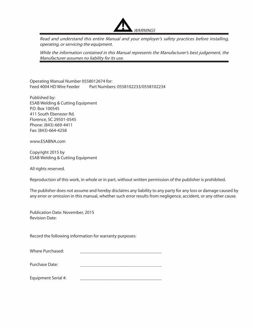
Operating Manual Number 0558012674 for:Feed 4004 HD Wire Feeder Part Numbers: 0558102233/0558102234
Published by:ESAB Welding & Cutting EquipmentP.O. Box 100545411 South Ebenezer Rd.Florence, SC 29501-0545Phone: (843)-669-4411Fax: (843)-664-4258
www.ESABNA.com
Copyright 2015 byESAB Welding & Cutting Equipment
All rights reserved.
Reproduction of this work, in whole or in part, without written permission of the publisher is prohibited.
The publisher does not assume and hereby disclaims any liability to any party for any loss or damage caused by any error or omission in this manual, whether such error results from negligence, accident, or any other cause.
Publication Date: November, 2015Revision Date:
Record the following information for warranty purposes:
Where Purchased: ____________________________________
Purchase Date: ____________________________________
Equipment Serial #: ____________________________________

This equipment will perform in conformity with the description thereof contained in this manual and accompa-nying labels and/or inserts when installed, operated, maintained and repaired in accordance with the instruc-tions provided. This equipment must be checked periodically. Malfunctioning or poorly maintained equipment should not be used. Parts that are broken, missing, worn, distorted or contaminated should be replaced imme-diately. Should such repair or replacement become necessary, the manufacturer recommends that a telephone or written request for service advice be made to the Authorized Distributor from whom it was purchased.
This equipment or any of its parts should not be altered without the prior written approval of the manufacturer. The user of this equipment shall have the sole responsibility for any malfunction which results from improper use, faulty maintenance, damage, improper repair or alteration by anyone other than the manufacturer or a ser-vice facility designated by the manufacturer.
Be sure this information reaches the operator.
You can get extra copies through your supplier.
These INSTRUCTIONS are for experienced operators. If you are not fully familiar with the principles of operation and safe practices for arc welding and cutting equipment, we urge you to read our booklet, “Precautions and Safe Practices for Arc Welding, Cutting, and Gouging,” Form 52-529. Do NOT permit untrained persons to install, operate, or maintain this equipment. Do NOT attempt to install or operate this equipment until you have read and fully understand these instructions. If you do not fully understand these instructions, contact your supplier for further information. Be sure to read the Safety Precautions be-fore installing or operating this equipment.
USER RESPONSIBILITY
READ AND UNDERSTAND THE INSTRUCTION MANUAL BEFORE INSTALLING OR OPERATING.
PROTECT YOURSELF AND OTHERS!
CAUTION

TABLE OF CONTENTS
1.01 Arc Welding Hazards . . . . . . . . . . . . . . . . . . . . . . . . . . . . . . . . . . . . . . . . . . . . . . . . . . . . . . . . . . . . . . . . . . . . . . . . . . . .71.02 Principal Safety Standards. . . . . . . . . . . . . . . . . . . . . . . . . . . . . . . . . . . . . . . . . . . . . . . . . . . . . . . . . . . . . . . . . . . . . .101.03 Symbol Chart . . . . . . . . . . . . . . . . . . . . . . . . . . . . . . . . . . . . . . . . . . . . . . . . . . . . . . . . . . . . . . . . . . . . . . . . . . . . . . . . . .11
SECTION 2: INTRODUCTION. . . . . . . . . . . . . . . . . . . . . . . . . . . . . . . . . . . . . . . . . . . . . . . . . . . . . . . . . . . . . . . . . . . . . . 132.01 How to Use This Manual. . . . . . . . . . . . . . . . . . . . . . . . . . . . . . . . . . . . . . . . . . . . . . . . . . . . . . . . . . . . . . . . . . . . . . . .132.02 Equipment Identification. . . . . . . . . . . . . . . . . . . . . . . . . . . . . . . . . . . . . . . . . . . . . . . . . . . . . . . . . . . . . . . . . . . . . . .132.03 Receipt of Equipment . . . . . . . . . . . . . . . . . . . . . . . . . . . . . . . . . . . . . . . . . . . . . . . . . . . . . . . . . . . . . . . . . . . . . . . . . .132.04 Description . . . . . . . . . . . . . . . . . . . . . . . . . . . . . . . . . . . . . . . . . . . . . . . . . . . . . . . . . . . . . . . . . . . . . . . . . . . . . . . . . . . .142.05 User Responsibility. . . . . . . . . . . . . . . . . . . . . . . . . . . . . . . . . . . . . . . . . . . . . . . . . . . . . . . . . . . . . . . . . . . . . . . . . . . . .142.06 Transportation Methods . . . . . . . . . . . . . . . . . . . . . . . . . . . . . . . . . . . . . . . . . . . . . . . . . . . . . . . . . . . . . . . . . . . . . . .142.07 Packaged Items . . . . . . . . . . . . . . . . . . . . . . . . . . . . . . . . . . . . . . . . . . . . . . . . . . . . . . . . . . . . . . . . . . . . . . . . . . . . . . . .152.08 Specifications. . . . . . . . . . . . . . . . . . . . . . . . . . . . . . . . . . . . . . . . . . . . . . . . . . . . . . . . . . . . . . . . . . . . . . . . . . . . . . . . . .152.09 Optional Accessories . . . . . . . . . . . . . . . . . . . . . . . . . . . . . . . . . . . . . . . . . . . . . . . . . . . . . . . . . . . . . . . . . . . . . . . . . . .16
SECTION 3: INSTALLATION, OPERATION and SETUP . . . . . . . . . . . . . . . . . . . . . . . . . . . . . . . . . . . . . . . . . . . . . . . 193.01 Environment. . . . . . . . . . . . . . . . . . . . . . . . . . . . . . . . . . . . . . . . . . . . . . . . . . . . . . . . . . . . . . . . . . . . . . . . . . . . . . . . . . .193.02 Location. . . . . . . . . . . . . . . . . . . . . . . . . . . . . . . . . . . . . . . . . . . . . . . . . . . . . . . . . . . . . . . . . . . . . . . . . . . . . . . . . . . . . . .193.03 Ventilation. . . . . . . . . . . . . . . . . . . . . . . . . . . . . . . . . . . . . . . . . . . . . . . . . . . . . . . . . . . . . . . . . . . . . . . . . . . . . . . . . . . . .193.04 Mains Supply Voltage Requirements. . . . . . . . . . . . . . . . . . . . . . . . . . . . . . . . . . . . . . . . . . . . . . . . . . . . . . . . . . . .193.05 Electromagnetic Compatibility . . . . . . . . . . . . . . . . . . . . . . . . . . . . . . . . . . . . . . . . . . . . . . . . . . . . . . . . . . . . . . . . .193.06 Front Panel Controls, Displays and Features . . . . . . . . . . . . . . . . . . . . . . . . . . . . . . . . . . . . . . . . . . . . . . . . . . . . 223.07 Rear Panel Controls and Features . . . . . . . . . . . . . . . . . . . . . . . . . . . . . . . . . . . . . . . . . . . . . . . . . . . . . . . . . . . . . . .243.08 Attaching the Tweco No. 4 MIG Torch . . . . . . . . . . . . . . . . . . . . . . . . . . . . . . . . . . . . . . . . . . . . . . . . . . . . . . . . . . 263.09 Installing Handle Assembly (Optional) . . . . . . . . . . . . . . . . . . . . . . . . . . . . . . . . . . . . . . . . . . . . . . . . . . . . . . . . . .273.10 Installing Lifting Eye Kit (Optional) . . . . . . . . . . . . . . . . . . . . . . . . . . . . . . . . . . . . . . . . . . . . . . . . . . . . . . . . . . . . . 283.11 Installing Tweco No. 5 Adaptor (Optional) . . . . . . . . . . . . . . . . . . . . . . . . . . . . . . . . . . . . . . . . . . . . . . . . . . . . . . 303.12 Installing Wire Spool Cover (optional) . . . . . . . . . . . . . . . . . . . . . . . . . . . . . . . . . . . . . . . . . . . . . . . . . . . . . . . . . . 393.13 Installing Welding Wire Spool . . . . . . . . . . . . . . . . . . . . . . . . . . . . . . . . . . . . . . . . . . . . . . . . . . . . . . . . . . . . . . . . . .423.14 Wire Reel Brake . . . . . . . . . . . . . . . . . . . . . . . . . . . . . . . . . . . . . . . . . . . . . . . . . . . . . . . . . . . . . . . . . . . . . . . . . . . . . . . 433.15 Inserting Wire into Feed Mechanism . . . . . . . . . . . . . . . . . . . . . . . . . . . . . . . . . . . . . . . . . . . . . . . . . . . . . . . . . . 443.16 Feed Roll Pressure Adjustment . . . . . . . . . . . . . . . . . . . . . . . . . . . . . . . . . . . . . . . . . . . . . . . . . . . . . . . . . . . . . . . . 453.17 Installing and Changing the Feed Roll / Removing Inlet Guide & Adaptor. . . . . . . . . . . . . . . . . . . . . . . . 45
SECTION 4: SERVICE . . . . . . . . . . . . . . . . . . . . . . . . . . . . . . . . . . . . . . . . . . . . . . . . . . . . . . . . . . . . . . . . . . . . . . . . . . . . . 474.01 Cleaning The Unit. . . . . . . . . . . . . . . . . . . . . . . . . . . . . . . . . . . . . . . . . . . . . . . . . . . . . . . . . . . . . . . . . . . . . . . . . . . . . .474.02 Cleaning The Feed Rolls . . . . . . . . . . . . . . . . . . . . . . . . . . . . . . . . . . . . . . . . . . . . . . . . . . . . . . . . . . . . . . . . . . . . . . . .474.03 System Maintenance . . . . . . . . . . . . . . . . . . . . . . . . . . . . . . . . . . . . . . . . . . . . . . . . . . . . . . . . . . . . . . . . . . . . . . . . . . .474.04 Troubleshooting Guide. . . . . . . . . . . . . . . . . . . . . . . . . . . . . . . . . . . . . . . . . . . . . . . . . . . . . . . . . . . . . . . . . . . . . . . . .474.05 MIG (GMAW/FCAW) Basic Welding Technique . . . . . . . . . . . . . . . . . . . . . . . . . . . . . . . . . . . . . . . . . . . . . . . . . . .474.06 MIG (GMAW/FCAW) Welding Troubleshooting . . . . . . . . . . . . . . . . . . . . . . . . . . . . . . . . . . . . . . . . . . . . . . . . . .534.07 Troubleshooting . . . . . . . . . . . . . . . . . . . . . . . . . . . . . . . . . . . . . . . . . . . . . . . . . . . . . . . . . . . . . . . . . . . . . . . . . . . . . . 56
SECTION 5: PARTS LIST . . . . . . . . . . . . . . . . . . . . . . . . . . . . . . . . . . . . . . . . . . . . . . . . . . . . . . . . . . . . . . . . . . . . . . . . . . 595.01 Equipment Identification. . . . . . . . . . . . . . . . . . . . . . . . . . . . . . . . . . . . . . . . . . . . . . . . . . . . . . . . . . . . . . . . . . . . . . .595.02 How To Use This Parts List . . . . . . . . . . . . . . . . . . . . . . . . . . . . . . . . . . . . . . . . . . . . . . . . . . . . . . . . . . . . . . . . . . . . . .595.03 Replacement Parts (without wirefeed plate) . . . . . . . . . . . . . . . . . . . . . . . . . . . . . . . . . . . . . . . . . . . . . . . . . . . 605.04 Replacement Parts- Wirefeed Plate . . . . . . . . . . . . . . . . . . . . . . . . . . . . . . . . . . . . . . . . . . . . . . . . . . . . . . . . . . . . 61
Appendix 1: CONNECTION DIAGRAM . . . . . . . . . . . . . . . . . . . . . . . . . . . . . . . . . . . . . . . . . . . . . . . . . . . . . . . . . . . . . 62
SECTION 1: GENERAL INFORMATION . . . . . . . . . . . . . . . . . . . . . . . . . . . . . . . . . . . . . . . . . . . . . . . . . . . . . . . . . . . . . . 7

TABLE OF CONTENTS
This page intentionally blank

7
SECTION 1: GENERAL INFORMATION
1.01 Arc Welding Hazards
WARNING
ELECTRIC SHOCK can kill.
Touching live electrical parts can cause fatal shocks or severe burns. The electrode and work circuit is electrically live whenever the output is on. The input power circuit and machine internal circuits are also live when power is on. In semi-automatic or automatic wire welding, the wire, wire reel, drive roll housing, and all metal parts touching the welding wire are electrically live. Incorrectly installed or improperly grounded equipment is a hazard.
1. Do not touch live electrical parts.
2. Wear dry, hole-free insulating gloves and body protec-tion.
3. Insulate yourself from work and ground using dry insulating mats or covers.
4. Disconnect input power or stop engine before install-ing or servicing this equipment. Lock input power disconnect switch open, or remove line fuses so power cannot be turned on accidentally.
5. Properly install and ground this equipment according to its Owner’s Manual and national, state, and local codes.
6. Turn off all equipment when not in use. Disconnect power to equipment if it will be left unattended or out of service.
7. Use fully insulated electrode holders. Never dip holder in water to cool it or lay it down on the ground or the work surface. Do not touch holders connected to two welding machines at the same time or touch other people with the holder or electrode.
8. Do not use worn, damaged, undersized, or poorly spliced cables.
9. Do not wrap cables around your body.
10. Ground the workpiece to a good electrical (earth) ground.
11. Do not touch electrode while in contact with the work (ground) circuit.
12. Use only well-maintained equipment. Repair or replace damaged parts at once.
13. In confined spaces or damp locations, do not use a welder with AC output unless it is equipped with a voltage reducer. Use equipment with DC output.
14. Wear a safety harness to prevent falling if working above floor level.
15. Keep all panels and covers securely in place.
! WARNING
PROTECT YOURSELF AND OTHERS FROM POSSIBLE SERIOUS INJURY OR DEATH. KEEP CHILDREN AWAY. PACE-MAKER WEARERS KEEP AWAY UNTIL CONSULTING YOUR DOCTOR. DO NOT LOSE THESE INSTRUCTIONS. READ OPERATING/INSTRUCTION MANUAL BEFORE INSTALLING, OPERATING OR SERVICING THIS EQUIPMENT.
Welding products and welding processes can cause serious injury or death, or damage to other equipment or property, if the operator does not strictly observe all safety rules and take precautionary actions.
Safe practices have developed from past experience in the use of welding and cutting. These practices must be learned through study and training before using this equipment. Some of these practices apply to equipment connected to power lines; other practices apply to engine driven equipment. Anyone not having extensive training in welding and cutting practices should not attempt to weld.
Safe practices are outlined in the Australian Standard AS1674.2-2007 entitled: Safety in Welding and Allied Pro-cesses Part 2: Electrical. This publication and other guides to what you should learn before operating this equip-ment are listed at the end of these safety precautions. HAVE ALL INSTALLATION, OPERATION, MAINTENANCE, AND REPAIR WORK PERFORMED ONLY BY QUALIFIED PEOPLE.

8
SECTION 1: GENERAL INFORMATION
WARNING
ARC RAYS can burn eyes and skin; NOISE can damage hearing.Arc rays from the welding process produce intense heat and strong ultraviolet rays that can burn eyes and skin. Noise from some processes can damage hearing.
1. Use a Welding Helmet or Welding Faceshield fitted with a proper shade of filter (see ANSI Z49.1 and AS 1674 listed in Safety Standards) to protect your face and eyes when welding or watching.
2. Wear approved safety glasses. Side shields recom-mended.
3. Use protective screens or barriers to protect others from flash and glare; warn others not to watch the arc.
4. Wear protective clothing made from durable, flame-re-sistant material (wool and leather) and foot protection.
5. Use approved ear plugs or ear muffs if noise level is high.
6. Never wear contact lenses while welding.
Recommended Protective Filters for Electric Welding
Description of Process Approximate Range of Welding Current in Amps
Minimum Shade Number of Filter(s)
Manual Metal Arc Welding - covered electrodes (MMAW)
Less than or equal to 100 8 100 to 200 10 200 to 300 11 300 to 400 12
Greater than 400 13
Gas Metal Arc Welding (GMAW) (MIG) other than Aluminium and Stainless Steel
Less than or equal to 150 10 150 to 250 11 250 to 300 12 300 to 400 13
Greater than 400 14 Gas Metal Arc Welding (GMAW) (MIG) Aluminium and Stainless Steel
Less than or equal to 250 12 250 to 350 13
Gas Tungsten Arc Welding (GTAW) (TIG)
Less than or equal to 100 10 100 to 200 11 200 to 250 12 250 to 350 13
Greater than 350 14
Flux-cored Arc Welding (FCAW) -with or without shielding gas.
Less than or equal to 300 11 300 to 400 12 400 to 500 13
Greater than 500 14
Air - Arc Gouging Less than or equal to 400 12
Plasma - Arc Cutting 50 to 100 10
100 to 400 12 400 to 800 14
Plasma - Arc Spraying — 15
Plasma - Arc Welding
Less than or equal to 20 8 20 to 100 10
100 to 400 12 400 to 800 14
Submerged - Arc Welding — 2(5) Resistance Welding — Safety Spectacles or eye shield
Refer to standard AS/NZS 1338.1:1992 for comprehensive information regarding the above table.Table 1-1 Protective Filters

9
SECTION 1: GENERAL INFORMATION
WARNING
FUMES AND GASES can be hazardous to your health.Welding produces fumes and gases. Breathing these fumes and gases can be hazardous to your health.
1. Keep your head out of the fumes. Do not breathe the fumes.
2. If inside, ventilate the area and/or use exhaust at the arc to remove welding fumes and gases.
3. If ventilation is poor, use an approved air-supplied respirator.
4. Read the Material Safety Data Sheets (MSDSs) and the manufacturer’s instruction for metals, consumables, coatings, and cleaners.
5. Work in a confined space only if it is well ventilated, or while wearing an air-supplied respirator. Shielding gases used for welding can displace air causing injury or death. Be sure the breathing air is safe.
6. Do not weld in locations near degreasing, cleaning, or spraying operations. The heat and rays of the arc can react with vapours to form highly toxic and irritating gases.
7. Do not weld on coated metals, such as galvanized, lead, or cadmium plated steel, unless the coating is removed from the weld area, the area is well venti-lated, and if necessary, while wearing an air-supplied respirator. The coatings and any metals containing these elements can give off toxic fumes if welded.
WARNING
WELDING can cause fire or explosion.Sparks and spatter fly off from the welding arc. The flying sparks and hot metal, weld spatter, hot workpiece, and hot equipment can cause fires and burns. Accidental contact of electrode or welding wire to metal objects can cause sparks, overheating, or fire.
1. Protect yourself and others from flying sparks and hot metal.
2. Do not weld where flying sparks can strike flammable material.
3. Remove all flammables within 10M of the welding arc. If this is not possible, tightly cover them with ap-proved covers.
4. Be alert that welding sparks and hot materials from welding can easily go through small cracks and open-ings to adjacent areas.
5. Watch for fire, and keep a fire extinguisher nearby.
6. Be aware that welding on a ceiling, floor, bulkhead, or partition can cause fire on the hidden side.
7. Do not weld on closed containers such as tanks or drums.
8. Connect work cable to the work as close to the weld-ing area as practical to prevent welding current from travelling long, possibly unknown paths and causing electric shock and fire hazards.
9. Do not use welder to thaw frozen pipes.
10. Remove stick electrode from holder or cut off welding wire at contact tip when not in use.
WARNING
FLYING SPARKS AND HOT METAL can cause injury.Chipping and grinding cause flying metal. As welds cool, they can throw off slag.
1. Wear approved face shield or safety goggles. Side shields recommended.
2. Wear proper body protection to protect skin.
WARNING
CYLINDERS can explode if damaged.Shielding gas cylinders contain gas under high pressure. If damaged, a cylinder can explode. Since gas cylinders are normally part of the welding process, be sure to treat them carefully.
1. Protect compressed gas cylinders from excessive heat, mechanical shocks, and arcs.
2. Install and secure cylinders in an upright position by chaining them to a stationary support or equipment cylinder rack to prevent falling or tipping.
3. Keep cylinders away from any welding or other electri-cal circuits.
4. Never allow a welding electrode to touch any cylinder.
5. Use only correct shielding gas cylinders, regulators, hoses, and fittings designed for the specific application; maintain them and associated parts in good condition.
6. Turn face away from valve outlet when opening cylinder valve.
7. Keep protective cap in place over valve except when cylinder is in use or connected for use.
8. Read and follow instructions on compressed gas cylinders, associated equipment, and CGA publication P-1 listed in Safety Standards.

10
SECTION 1: GENERAL INFORMATION
WARNING
MOVING PARTS can cause injury.
Moving parts, such as fans, rotors, and belts can cut fingers and hands and catch loose clothing.1. Keep all doors, panels, covers, and guards closed and
securely in place.
2. Stop engine before installing or connecting unit.
3. Have only qualified people remove guards or covers for maintenance and troubleshooting as necessary.
4. To prevent accidental starting during servicing, dis-connect negative (-) battery cable from battery.
5. Keep hands, hair, loose clothing, and tools away from moving parts.
6. Reinstall panels or guards and close doors when ser-vicing is finished and before starting engine.
! WARNING
This product, when used for welding or cutting, produces fumes or gases which contain chemi-cals know to the State of California to cause birth defects and, in some cases, cancer. (California Health & Safety code Sec. 25249.5 et seq.)
NOTEConsiderations About Welding And The
Effects of Low Frequency Electric and Mag-netic FieldsThe following is a quotation from the General Con-
clusions Section of the U.S. Congress, Office of Technology Assessment, Biological Effects of Power Frequency Electric & Magnetic Fields - Background Paper, OTA-BP-E-63 (Washington, DC: U.S. Government Printing Office, May 1989): “...there is now a very large volume of scientific findings based on experiments at the cellular level and from studies with animals and people which clearly establish that low frequency magnetic fields and interact with, and produce changes in, biological systems. While most of this work is of very high quality, the results are complex. Current scientific understanding does not yet allow us to interpret the evidence in a single coherent framework. Even more frustrating, it does not yet allow us to draw definite conclusions about questions of possible risk or to offer clear science-based advice on strategies to minimize or avoid potential risks.”
To reduce magnetic fields in the workplace, use the following procedures.1. Keep cables close together by twisting or taping them.
2. Arrange cables to one side and away from the opera-tor.
3. Do not coil or drape cable around the body.
4. Keep welding power source and cables as far away from body as practical.
ABOUT PACEMAKERS:
The above procedures are among those also normally recommended for pacemaker wearers. Consult your doctor for complete information.
1.02 Principal Safety StandardsSafety in Welding and Cutting, ANSI Standard Z49.1,
from American Welding Society, 550 N.W. LeJeune Rd., Miami, FL 33126.
Safety and Health Standards, OSHA 29 CFR 1910, from Superintendent of Documents, U.S. Government Printing Office, Washington, D.C. 20402.
Recommended Safe Practices for the Preparation for Welding and Cutting of Containers That Have Held Hazardous Substances, American Welding Society Stan-dard AWS F4.1, from American Welding Society, 550 N.W. LeJeune Rd., Miami, FL 33126.
National Electrical Code, NFPA Standard 70, from National Fire Protection Association, Batterymarch Park, Quincy, MA 02269.
Safe Handling of Compressed Gases in Cylinders, CGA Pamphlet P-1, from Compressed Gas Association, 1235 Jefferson Davis Highway, Suite 501, Arlington, VA 22202.
Code for Safety in Welding and Cutting, CSA Stan-dard W117.2, from Canadian Standards Association, Standards Sales, 178 Rexdale Boulevard, Rexdale, Ontario, Canada M9W 1R3.
Safe Practices for Occupation and Educational Eye and Face Protection, ANSI Standard Z87.1, from American National Standards Institute, 1430 Broadway, New York, NY 10018.
Cutting and Welding Processes, NFPA Standard 51B, from National Fire Protection Association, Batterymarch Park, Quincy, MA 02269.
Safety in Welding and Allied Processes Part 1: Fire Precautions, AS 1674.1-1997 from SAI Global Limited, www.saiglobal.com.
Safety in Welding and Allied Processes Part 2: Electrical, AS 1674.2-2007 from SAI Global Limited, www.saiglobal.com.
Filters for Eye Protectors - Filters for protection against radiation generated in welding and allied opera-tions AS/NZS 1338.1:1992 from SAI Global Limited, www.saiglobal.com. 1

11
SECTION 1: GENERAL INFORMATION
1.03 Symbol ChartNote that only some of these symbols will appear on your model.
Gas Tungsten Arc Welding (GTAW)
Air Carbon Arc Cutting (CAC-A)
Constant Current
Constant Voltage Or Constant Potential
High Temperature
Fault Indication
Arc Force
Touch Start (GTAW)
Variable Inductance
Voltage Input
Single Phase
Three Phase
Three Phase Static Frequency Converter-Transformer-Recti�er
Dangerous Voltage
O�
On
Panel/Local
Manual Metal Arc Welding (MMAW)
Gas Metal Arc Welding (GMAW)
Increase/Decrease
Circuit Breaker
AC Auxiliary Power
Remote
Duty Cycle
Slow Run-In
Amperage
Voltage
Hertz (cycles/sec)
Frequency
Negative
Positive
Direct Current (DC)
Protective Earth (Ground)
Line
Line Connection
Auxiliary Power
Receptacle Rating-Auxiliary Power
115V 15A
t
t1
t2
X
IPM
MPM
t
V
Fuse
Wire Feed Function
Wire Feed Towards Workpiece With Output Voltage O�.
Pre�ow Time
Post�ow Time
Spot Time
Spot Weld Mode
Continuous WeldMode
Press to initiate wirefeed and welding, release to stop.
Purging Of Gas
Inches Per Minute
Metres Per Minute
Gas Inlet
Welding Torch
Burnback Time
Press and hold for pre�ow, releaseto start arc. Press to stop arc, andhold for pre�ow.
4 Step TriggerOperation
2 Step TriggerOperation
Solid Wire
Cored Wire
Figure 1-1 Symbol Chart

12
SECTION 1: GENERAL INFORMATION
This page intentionally blank

SECTION 2: INTRODUCTION
2.02 Equipment IdentificationThe unit’s identification number (specification or part number), model, and serial number usually appear on a nameplate attached to the ma-chine. Equipment which does not have a name-plate attached to the machine is identified only by the specification or part number printed on the shipping container. Record these numbers for future reference.
2.03 Receipt of EquipmentWhen you receive the equipment, check it against the invoice to make sure it is complete and inspect the equipment for possible dam-age due to shipping. If there is any damage, notify the carrier immediately to file a claim. Furnish complete information concerning dam-age claims or shipping errors to the location in your area listed in the inside back cover of this manual.Include all equipment identification numbers as described above along with a full description of the parts in error.Move the equipment to the installation site before un-crating the unit. Use care to avoid damaging the equipment when using bars, hammers, etc., to un-crate the unit.
2.01 How to Use This ManualTo ensure safe operation, read the entire manu-al, including the chapter on safety instructions and warnings. Throughout this manual, the word WARNING, CAUTION and NOTE may ap-pear. Pay particular attention to the information provided under these headings. These special annotations are easily recognized as follows:
! WARNING
Gives information regarding possible personal injury. Warn-ings will be enclosed in a box such as this.
CAUTION
Refers to possible equipment damage. Cautions will be shown in bold type.
NOTEOffers helpful information concerning certain operating procedures. Notes
will be shown in italics.
Additional copies of this manual may be purchased by contacting ESAB at the address and phone number
for your location listed in the inside back cover of this manual. Include the Owner’s Manual number and equip-
ment identification numbers.

14
SECTION 2: INTRODUCTION
2.04 DescriptionThe Feed 4004 HD Wire Feeder offers both load and line voltage compensation helping to maintain a constant wire feed speed, even with changes in the input voltage and/or load.The Feed 4004 HD Wire Feeder’s sheet metal box totally encloses the solid state control circuitry. A hinged, latched feedhead cover allows quick and easy access to the feedhead featuring quick change feed rolls, and tool-less knobs and clamps for changeover of guides and guns. The Feed 4004 HD Wire Feeder comes with an abundance of standard features including:
• ControlPaneloptionsforU6orU82
• anon/offrockerswitch
• awirefeedspeedcontrol
• apowersourcevoltagecontrol
• twoquickchange,gear-drivenfeedrolls
• agasvalvesolenoid
• anisolatedguntriggerforoperatorsafety
• avarietyofadd-onoptionstoconfiguretheunit for any wire-welding situation.
The Feed 4004 HD Wire Feeder has been designed to comply with CSA NRTL/C, NEMA EW 3, IEC 60974-1, IEC 60974-5 and IEC 60974-10 standards.
The instructions in the next section detail how to correctly and safely set up the machine and give guidelines on gaining the best efficiency and quality from the Power Source. Please read these instructions thoroughly before using the unit.
2.05 User ResponsibilityThis equipment will perform as per the informa-tion contained herein when installed, operated, maintained and repaired in accordance with the instructions provided. This equipment must be checked periodically. Defective equipment (in-cluding welding leads) should not be used. Parts that are broken, missing, plainly worn, distorted or contaminated, should be replaced immediate-ly. Should such repairs or replacements become necessary, it is recommended that such repairs be carried out by appropriately qualified persons approved by ESAB. Advice in this regard can be obtained by contacting an Accredited ESAB Distributor.This equipment or any of its parts should not be altered from standard specification without prior written approval of ESAB. The user of this equipment shall have the sole responsibility for any malfunction which results from improper use or unauthorized modification from standard specification, faulty maintenance, damage or improper repair by anyone other than appropri-ately qualified persons approved by ESAB.
2.06 Transportation Methods
!WARNING
ELECTRIC SHOCK can kill. DO NOT TOUCH live electrical parts. Disconnect wire feeder from Power Source before moving the wire feeder.
! WARNING
FALLING EQUIPMENT can cause serious personal injury and equipment damage.
Lift unit with optional handle at the top of the unit. Use handcart or similar device of adequate capacity. If using a fork lift vehicle, place and secure unit on a proper skid before transporting.
15
SECTION 2: INTRODUCTION
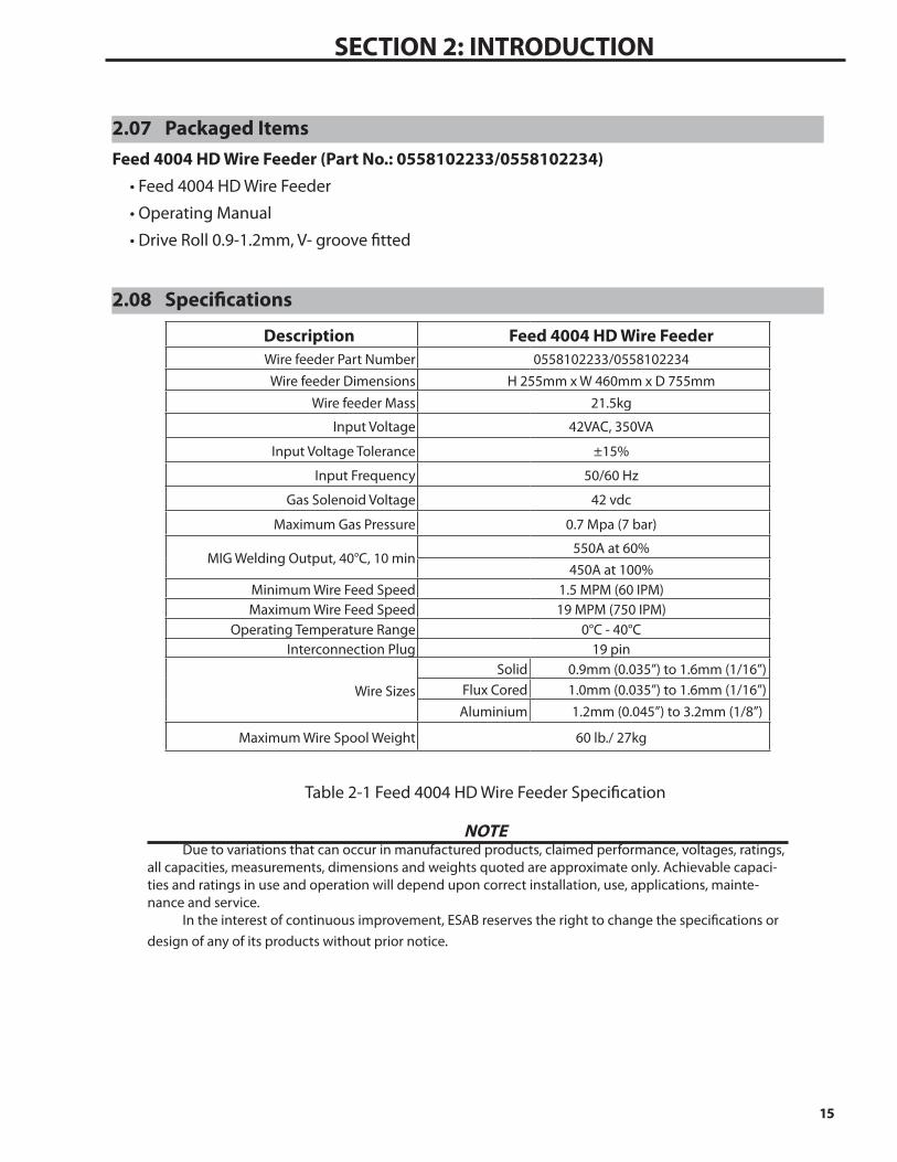
2.07 Packaged ItemsFeed 4004 HD Wire Feeder (Part No.: 0558102233/0558102234)•Feed4004HDWireFeeder
•OperatingManual
•DriveRoll0.9-1.2mm,V-groovefitted
2.08 Specifications
Description Feed 4004 HD Wire FeederWire feeder Part Number 0558102233/0558102234Wire feeder Dimensions H 255mm x W 460mm x D 755mm
Wire feeder Mass 21.5kg
Input Voltage 42VAC, 350VA
Input Voltage Tolerance ±15%
Input Frequency 50/60 Hz
Gas Solenoid Voltage 42 vdc
Maximum Gas Pressure 0.7 Mpa (7 bar)
MIG Welding Output, 40°C, 10 min 550A at 60%
450A at 100%Minimum Wire Feed Speed 1.5 MPM (60 IPM)Maximum Wire Feed Speed 19 MPM (750 IPM)
Operating Temperature Range 0°C - 40°CInterconnection Plug 19 pin
Wire SizesSolid 0.9mm (0.035”) to 1.6mm (1/16”)
Flux Cored 1.0mm (0.035”) to 1.6mm (1/16”)Aluminium 1.2mm (0.045”) to 3.2mm (1/8”)
Maximum Wire Spool Weight 60 lb./ 27kg
Table 2-1 Feed 4004 HD Wire Feeder Specification
NOTE Due to variations that can occur in manufactured products, claimed performance, voltages, ratings,
all capacities, measurements, dimensions and weights quoted are approximate only. Achievable capaci-ties and ratings in use and operation will depend upon correct installation, use, applications, mainte-nance and service.
In the interest of continuous improvement, ESAB reserves the right to change the specifications or design of any of its products without prior notice.

16
SECTION 2: INTRODUCTION
2.09 Optional AccessoriesFeed Rolls & Guides
Warrior Feed 404HD Feed Rolls (as delivered -*) Guides (as delivered -*)
Wire Diameter: in. (mm)
Type Part Number Qty Guide Tube Qty Center Guide
Qty Inlet Guide Qty
.035 (0.9)-.045 (1.2) V-Solid 0558102372* set of 2
0558102387* 1 0558102389* 1 0558102390* 1
.035 (0.9)-.035 (0.9) V-Solid 0558102374 set of 2
0558102387 1 0558102389 1 0558102390 1
.045 (1.2)-.045 (1.2) V-Solid 0558102375 set of 2
0558102387 1 0558102389 1 0558102390 1
.045 (1.2)/.052 (1.4)-.062 (1.6)
V-Solid 0558102373 set of 2
0558102387 1 0558102389 1 0558102390 1
.030 (0.8)/.035 (0.9)-.045 (1.2)
K-Cored 0558102379 set of 2
0558102387 1 0558102389 1 0558102390 1
.045 (1.2)-.045 (1.2) K-Cored 0558102384 set of 2
0558102387 1 0558102389 1 0558102390 1
.045 (1.2) /.052 (1.4 )- 1/16 (1.6)
K-Cored 0558102380 set of 2
0558102387 1 0558102389 1 0558102390 1
.052 (1.4)-.052 (1.4) K-Cored 0558102385 set of 2
0558102387 1 0558102389 1 0558102390 1
1/16 (1.6)-1/16 (1.6) K-Cored 0558102386 set of 2
0558102387 1 0558102389 1 0558102390 1
5/64-3/32" K-Cored 0558102381 set of 2
N/A 1 0558102389 1 0558102390 1
7/64" K-Cored 0558102382 set of 2
N/A 1 0558102389 1 0558102390 1
1/8" K-Cored 0558102383 set of 2
N/A 1 0558102389 1 0558102390 1
3/64 - 1/16" U-Soft 0558102377 set of 2
N/A 1 0558102389 1 0558102390 1
5/64” - 3/32” U-Soft 0558102378 set of 2
N/A 1 0558102389 1 0558102390 1
Table 2-2 Feed Rolls
note : Two feed rolls are required for each wire size.note : * indicates fitted as standard.

17
SECTION 2: INTRODUCTION
Other Accessories
Table 2-3 Options and Accessories
Ordering Information – Accessories
Description Part NumberOKC50 Connectors female cable connector, 1/0-4/0 cable (50 mm²) 13735631 (0160361881)
OKC50 Connectors male cable connector, 1/0-4/0 cable (50 mm²) 13792513 (0160360881)
Marathon Pac Conduit QC Adaptor Kit 899F50
Lifting Eye Kit W4016701
Heavy Duty 4 Wheel Trolley W4000002
CONN SET 5.6FT 10/10P 500A 0459528780
CONN SET 16.4FT 10/10P 500A 0459528781
CONN SET 32.8FT 10/10P 500A 0459528782
CONN SET 49.2FT 10/10P 500A 0459528783
CONN SET 82FT 10/10P 500A 0459528784
CONNECT SET 500A 10/10P 35M 0459528785
V350A Spray Master 15ft. Air-cooled MIG Gun (SVM315-116) 1036-1756
V450A Spray Master 15ft. Air-cooled MIG Gun (SVM415-116) 1040-1833

18
SECTION 2: INTRODUCTION
Other Accessories

3.01 EnvironmentThese units are designed for use in environ-
ments with increased hazard of electric shock as outlined in IEC 60974.5.
A. Examples of environments with in-creased hazard of electric shock are:1. In locations in which freedom of movement
is restricted, so that the operator is forced to perform the work in a cramped (kneeling, sitting or lying) position with physical contact with conductive parts.
2. In locations which are fully or partially limited by conductive elements, and in which there is a high risk of unavoidable or accidental contact by the operator.
3. In wet or damp hot locations where humidity or perspiration considerably reduces the skin resistance of the human body and the insula-tion properties of accessories.
B. Environments with increased hazard of electric shock do not include places where elec-trically conductive parts in the near vicinity of the operator, which can cause increased hazard, have been insulated.
3.02 LocationBe sure to locate the Wire feeder according
to the following guidelines:A. In areas, free from moisture and dust.
B. Ambient temperature between 0° C to 40° C.
C. In areas, free from oil, steam and corrosive gases.
D. In areas, not subjected to abnormal vibration or shock.
E. In areas, not exposed to direct sunlight or rain.
F. The enclosure design of this Wire Feeder meets the requirements of IP23S as outlined in AS 60529. This provides adequate pro-tection against solid objects (greater than 12mm), and from water falling as spray at an angle up to 60o from vertical. Under no circumstances should the unit be operated or connected in a micro environment that will exceed the stated conditions. For further information please refer to AS 60529.
G. Precautions must be taken against the Wire Feeder toppling over. The Wire Feeder must be located on a suitable horizontal surface in the upright position when in use.
3.03 Ventilation
!WARNING
Since the inhalation of welding fumes can be harmful, ensure that the welding area is effectively ventilated.
3.04 Mains Supply Voltage Requirements
CAUTION
This Wire feeder cannot be con-nected directly to the mains supply. It must be connected to a suitable Wire feeder control socket on a power source.
3.05 Electromagnetic Compatibility
! WARNING
Extra precautions for Electromagnetic Compatibility may be required when this Welding Power Source is used in a domestic situation.
SECTION 3: INSTALLATION, OPERATION and SETUP

20
SECTION 3: installation, Operation and Setup
A. Installation and Use - Users ResponsibilityThe user is responsible for installing and
using the welding equipment according to the manufacturer’s instructions. If electromagnetic disturbances are detected then it shall be the responsibility of the user of the welding equip-ment to resolve the situation with the technical assistance of the manufacturer. In some cases this remedial action may be as simple as earth-grounding the welding circuit, see NOTE below. In other cases it could involve constructing an electromagnetic screen enclosing the Weld-ing Power Source and the work, complete with associated input filters. In all cases, electromag-netic disturbances shall be reduced to the point where they are no longer troublesome.
NOTEThe welding circuit may or may
not be earthed for safety reasons. Changing the earth-grounding ar-
rangements should only be authorised by a person who is competent to as-
sess whether the changes will increase the risk of injury, e.g. by allowing paral-lel welding current return paths which
may damage the grounding circuits of other equipment. Further guidance is given in IEC 60974-13 Arc Welding Equipment - Installation and use (un-
der preparation).
B. Assessment of AreaBefore installing welding equipment, the
user shall make an assessment of potential elec-tromagnetic problems in the surrounding area. The following shall be taken into account.1. Other supply cables, control cables, signal-
ling and telephone cables; above, below and adjacent to the welding equipment.
2. Radio and television transmitters and receiv-ers.
3. Computer and other control equipment.
4. Safety critical equipment, e.g. guarding of industrial equipment.
5. The health of people around, e.g. the use of pace-makers and hearing aids.
6. Equipment used for calibration and measure-ment.
7. The time of day that welding or other activi-ties are to be carried out.
8. The immunity of other equipment in the environment: the user shall ensure that other equipment being used in the environment is compatible: this may require additional protection measures.
The size of the surrounding area to be considered will depend on the structure of the building and other activities that are taking place. The surrounding area may extend beyond the boundaries of the premises.

21
SECTION 3: INSTALLATION, OpErATION AND SETUp
C. Methods of Reducing Electromagnetic Emissions
1. Mains Supply
Welding equipment should be connected to the mains supply according to the manu-facturer’s recommendations. If interference occurs, it may be necessary to take additional precautions such as filtering of the mains supply. Consideration should be given to shielding the supply cable of permanently installed welding equipment in metallic conduit or equivalent. Shielding should be electrically continuous throughout its length. The shielding should be connected to the Welding Power Source so that good electrical contact is maintained between the conduit and the Welding Power Source enclosure.
2. Maintenance of Welding Equipment
The welding equipment should be routinely maintained according to the manufacturer’s recommendations. All access and service doors and covers should be closed and prop-erly fastened when the welding equipment is in operation. The welding equipment should not be modified in any way except for those changes and adjustments covered in the manufacturer’s instructions.
3. Welding Cables
The welding cables should be kept as short as possible and should be positioned close together but never coiled and running at or close to the floor level.
4. Equipotential Bonding
Bonding of all metallic components in the welding installation and adjacent to it should be considered. However, metallic compo-nents bonded to the work piece will increase the risk that the operator could receive a shock by touching the metallic components and the electrode at the same time. The operator should be insulated from all such bonded metallic components.
5. Earthing/grounding of the Work Piece
Where the work piece is not bonded to earth for electrical safety, nor connected to earth because of its size and position, e.g. ship’s hull or building steelwork, a connection bonding the work piece to earth may reduce emissions in some, but not all instances. Care should be taken to prevent the earthing of the work piece increasing the risk of injury to users, or damage to other electrical equip-ment. Where necessary, the connection of the work piece to earth should be made by direct connection to the work piece, but in some countries where direct connection is not permitted, the bonding should be achieved by suitable capacitance, selected according to national regulations.
6. Screening and Shielding
Selective screening and shielding of other cables and equipment in the surrounding area may alleviate problems of interference. Screening the entire welding installation may be considered for special applications.
22
SECTION 3: installation, Operation and Setup
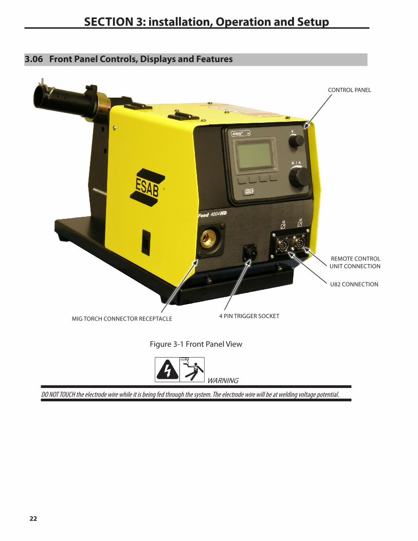
3.06 Front Panel Controls, Displays and Features
Figure 3-1 Front Panel View
WARNING
DO NOT TOUCH the electrode wire while it is being fed through the system. The electrode wire will be at welding voltage potential.
CONTROL PANEL
REMOTE CONTROL UNIT CONNECTION
4 PIN TRIGGER SOCKETMIG TORCH CONNECTOR RECEPTACLE
U82 CONNECTION

23
SECTION 3: INSTALLATION, OpErATION AND SETUp
123
4
1 2
3 4
Trigger Switch
Figure 3-3 4 Pin Trigger Socket
Socket Pin Function
1 Trigger Switch Input
2 Trigger Switch Input
3 Not connected
4 Not connected
Table 3-2 Pin Function in 4 Pin Trigger Socket
The wire feed unit is supplied with one of the following control panels:
U6
Empty panel for use with double wire feed units orwith use of control box U82.
Knobs for setting the voltage and the wire feed speed/ current. Other parameters are controlled bypushbuttons, with text in the display panel.
Connections and control devices
Connection for remote control unit The 12 pin connector is used to connect a remote control unit to the wirefeeder. To make connection, align
keyway, insert plug and rotate threaded collar fully clockwise.
Connection for U82 The 12 pin connector is used to connect the U82 control box to the feeder units without control panels
installed (MO). To make connection, align keyway, insert plug and rotate threaded collar fully clockwise.
Control Panel, (see separate instruction manual)
MIG Torch Connector Receptacle The MIG Torch adaptor is the connection
point for the MIG welding Torch. Connect the MIG Torch by pushing the MIG Torch connec-tor into the brass MIG Torch adaptor firmly and tightening the plastic MIG Torch nut clockwise to secure in position. To remove the MIG Torch simply reverse these direc-tions.
4 Pin Trigger SocketThe 4 pin Trigger Socket is used to con-nect the torch trigger switch to the welding power source. To make connections, align keyway, insert plug, and rotate threaded col-lar fully clockwise.

24
SECTION 3: installation, Operation and Setup
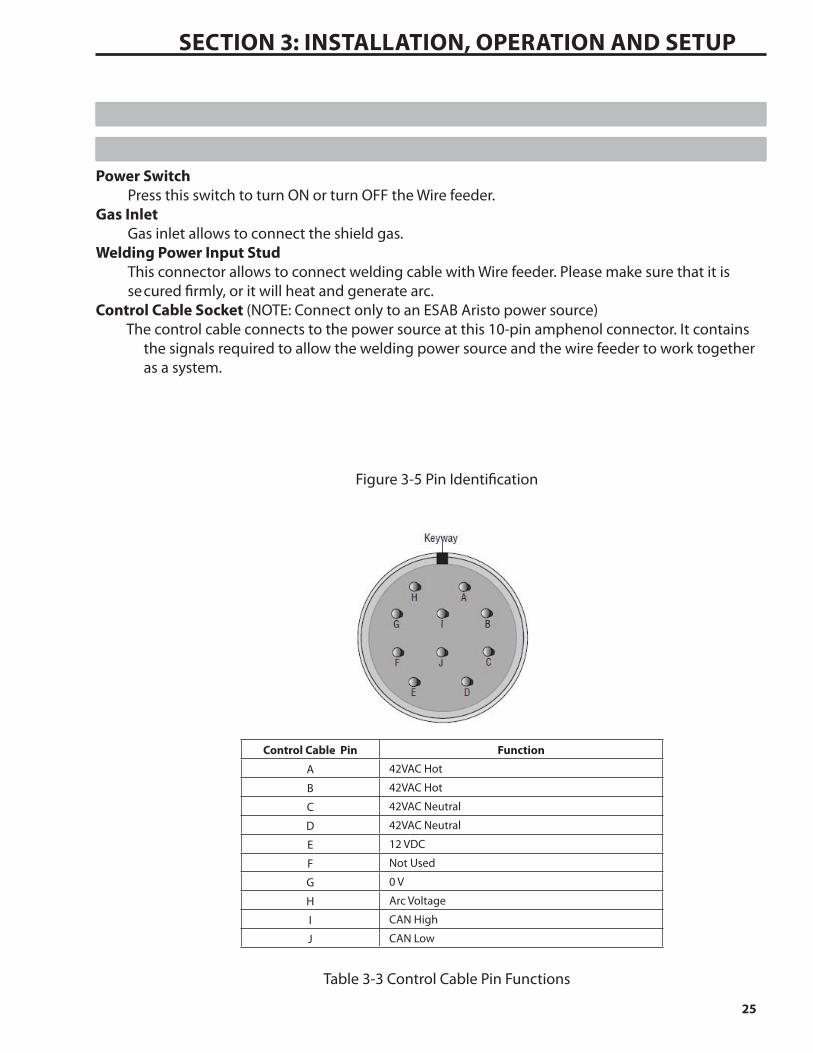
CONTROL CABLE SOCKET
WIRE GUIDEREEL STAND WELDING POWER
INPUT STUD
DOOR LATCH
WIRE SPOOL HUB
POWER SWITCH
GAS INLET
Figure 3-4 Rear Panel View
3.07 Rear Panel Controls and Features
25
SECTION 3: INSTALLATION, OpErATION AND SETUp
Power SwitchPress this switch to turn ON or turn OFF the Wire feeder.
Gas InletGas inlet allows to connect the shield gas.
Welding Power Input StudThis connector allows to connect welding cable with Wire feeder. Please make sure that it is se cured firmly, or it will heat and generate arc.
Control Cable Socket (NOTE: Connect only to an ESAB Aristo power source) The control cable connects to the power source at this 10-pin amphenol connector. It contains
the signals required to allow the welding power source and the wire feeder to work together as a system.
Figure 3-5 Pin Identification
Table 3-3 Control Cable Pin Functions
Control Cable Pin Function
A 42VAC Hot
B 42VAC Hot
C 42VAC Neutral
D 42VAC Neutral
E 12 VDC
F Not Used
G 0 V
H Arc Voltage
I CAN High
J CAN Low

26
SECTION 3: installation, Operation and Setup
Figure 3-7 Attaching the Tweco No. 4 MIG Torch
3.08 Attaching the Tweco No. 4 MIG Torch1. Insert the 4 pin plug into the 4 Pin Trigger Socket, and rotate threaded collar fully clockwise to
lock the plug into position.
2. Fit the Tweco No. 4 MIG torch to the Wire feeder by pushing the MIG Torch Connector into the Tweco No. 4 Torch Adaptor and secure it by tightening the Thumb Screw.
Tweco No. 4 MIG Torch Connector
4 Pin Plug
4 Pin Trigger Socket
Thumb Screw
Art # A-11757
Tweco No. 4 MIG Torch

27
SECTION 3: INSTALLATION, OpErATION AND SETUp
3.09 Installing Handle Assembly (Optional)
! warning
This handle is not designed to lift Wire feeder by mechanical means. Handle is to be used for Lifting by Hand Only.
For Mechanical Lifting use Lifting Eye Kit W4016700.
The following components are included:
Description QuantityHandle Assembly 1
Bolt, M10 × 50 (with torque 45~59 N.m.) 2Flat Washer, M10 (with torque 45~59 N.m.) 4
Spring Washer, M10 (with torque 45~59 N.m.) 2
Nut, M10 (with torque 45~59 N.m.) 2
Table 3-7 Handle Assembly
Install the handle assembly as below:Secure the handle assembly to the base assembly with M10 x 50 Bolts, M10 Flat Washers, M10
Spring Washers and M10 Nuts as shown in Figure 3-8.
Bolt, M10 × 50
Flat Washer, M10
Spring Washer, M10
Nut, M10
Handle Assembly
Figure 3-8 Installing Handle Assembly
! warning
Fully tighten all the fasteners with torque 45~59 N.m.
Refer to the figure below for the assembled handle assembly:

28
SECTION 3: installation, Operation and Setup
Handle Assembly
Figure 3-9 Assembled Handle Assembly
3.10 Installing Lifting Eye Kit (Optional)The following components are included:
Description QuantityLifting Eye 1
Insulator Plate 1Bolt, M8 × 40 (with torque 45~59 N.m.) 2
Flat Washer (smaller), M8 (with torque 45~59 N.m.) 2Flat Washer (larger), M8 (with torque 45~59 N.m.) 2
Insulator Washer, M8 (with torque 45~59 N.m.) 2
Spring Washer, M8 (with torque 45~59 N.m.) 2
Nut, M8 (with torque 45~59 N.m.) 2
Table 3-7 Lifting Eye Kit
Install the lifting eye as below:1. Loosen the M10 x 50 Bolts, M10 Flat Washers, M10 Spring Washers and M10 Nuts with 17mm
wrench that secure the handle assembly and remove the handle assembly and fixings from the base assembly. Refer to Figure 3-8.
2. Use 14mm wrench to secure the lifting eye and insulator plate to the base assembly using the M8 x 40 Bolts, M8 Flat Washers, M8 insulator washers, M8 Spring Washers and M8 Nuts as sup-plied with this kit.

29
SECTION 3: INSTALLATION, OpErATION AND SETUp
Lifting Eye
Bolt, M8 × 40
Flat Washer (smaller), M8
Insulator Washer, M8
Flat Washer (larger), M8
Spring Washer, M8Nut, M8
Insulator Plate
Figure 3-10 Installing Lifting Eye
! warning
Fully tighten all the fasteners with torque 45~59 N.m.
Refer to the figure below for the assembled lifting eye.
Lifting Eye
Figure 3-11 Assembled Lifting Eye

30
SECTION 3: installation, Operation and Setup
3.11 Installing Tweco No. 5 Adaptor (Optional)
WARNING
There are dangerous voltage and power levels inside this product. Turn OFF Wire feeder and disconnect from the power source before installing kit.
The following components are included in this kit:
Description Quantity
Torch Adaptor, Tweco No. 5 1
Outlet Guide 1
Set Screw, M4 ×6 1
Lock Washer, M12 1
Lock Nut, M12 1
Gas Hose, 170mm 1
Hose Clamp, ø 8.7 2
Wire Tie 2
Allen Key, 2mm 1
Table 3-9 Tweco No 5 MIG Torch Adaptor Assembly
Removing Tweco No. 4 MIG Torch Adaptor
1. Remove the top cover from the base.
a. Open side door to access door grounding wire.
b. Disconnect the grounding wire from the door and then close the door again.
c. Remove the six screws on the top cover and the four screws on the side of the cover, then remove the cover. Keep the screws for future use.

31
SECTION 3: INSTALLATION, OpErATION AND SETUp
Art # A-11762
Grounding Wire
Figure 3-12 Removing Grounding Wire
Art # A-11763_AB
Screw Hole
Screw
Screw
(Note: Some screws not shown for clarity of picture)
Figure 3-13 Removing the Cover
32
SECTION 3: installation, Operation and Setup
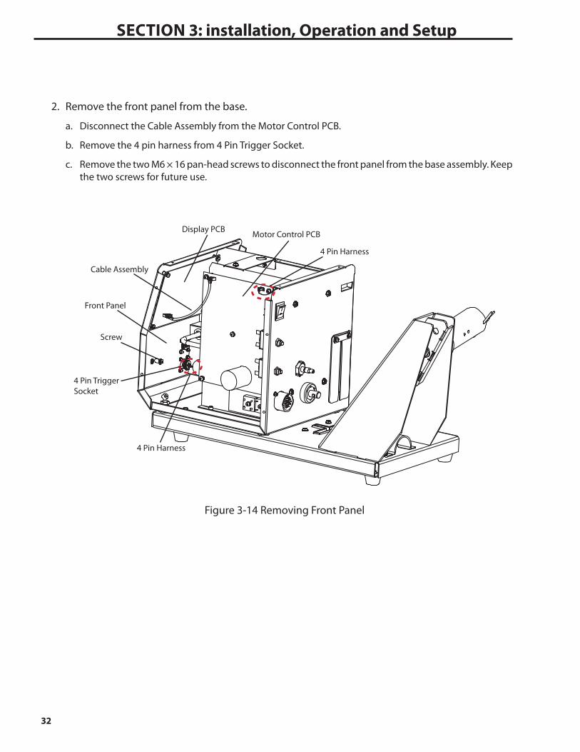
2. Remove the front panel from the base.
a. Disconnect the Cable Assembly from the Motor Control PCB.
b. Remove the 4 pin harness from 4 Pin Trigger Socket.
c. Remove the two M6 × 16 pan-head screws to disconnect the front panel from the base assembly. Keep the two screws for future use.
Motor Control PCBDisplay PCB
Cable Assembly
Screw
Front Panel
4 Pin Harness
4 Pin Harness
4 Pin Trigger Socket
Figure 3-14 Removing Front Panel
33
SECTION 3: INSTALLATION, OpErATION AND SETUp
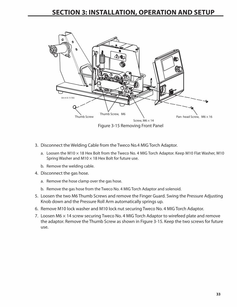
Art # A-11765
Pan- head Screw,M6 × 16 Thumb ScrewScrew, M6 × 14
Thumb Screw,M6
Figure 3-15 Removing Front Panel
3. Disconnect the Welding Cable from the Tweco No.4 MIG Torch Adaptor.
a. Loosen the M10 × 18 Hex Bolt from the Tweco No. 4 MIG Torch Adaptor. Keep M10 Flat Washer, M10 Spring Washer and M10 × 18 Hex Bolt for future use.
b. Remove the welding cable.
4. Disconnect the gas hose.
a. Remove the hose clamp over the gas hose.
b. Remove the gas hose from the Tweco No. 4 MIG Torch Adaptor and solenoid.
5. Loosen the two M6 Thumb Screws and remove the Finger Guard. Swing the Pressure Adjusting Knob down and the Pressure Roll Arm automatically springs up.
6. Remove M10 lock washer and M10 lock nut securing Tweco No. 4 MIG Torch Adaptor.
7. Loosen M6 × 14 screw securing Tweco No. 4 MIG Torch Adaptor to wirefeed plate and remove the adaptor. Remove the Thumb Screw as shown in Figure 3-15. Keep the two screws for future use.

34
SECTION 3: installation, Operation and Setup
Welding Cable
Gas Hose
Hose Clamp
Hex Bolt, M10 × 18
Spring Washer, M10
Flat Washer, M10
SolenoidArt # A-11766
Figure 3-16 Removing Tweco No.4 MIG Torch Adaptor
Connecting Gas Hose to Solenoid1. Place the hose clamp over the solenoid outlet.
2. Push gas hose onto solenoid outlet.
3. Slide the hose clamp over gas hose and tighten it with suitable crimping tool.
Hose ClampGas Hose Connected Gas Hose
Art # A-11635
Solenoid Outlet Solenoid
Figure 3-17 Connecting Gas Hose to Solenoid
Connecting Gas Hose to Tweco No. 5 Adaptor1. Place the hose clamp over gas hose.
2. Push the gas hose onto the Tweco No. 5 Torch Adaptor gas inlet.
3. Slide the hose clamp forward until it sits approximately 5mm from the end of the gas hose.
4. Tighten the hose clamp with a suitable crimping tool.

35
SECTION 3: INSTALLATION, OpErATION AND SETUp
Torch Adaptor, Tweco No. 5
Hose Clamp
Gas HoseTorch Adaptor, Tweco No. 5
Gas Hose
Art # A-11767
Figure 3-18 Connecting Gas Hose to Tweco No. 5 Adaptor
Connecting Welding Cable to Tweco No. 5 Adaptor1. Attach the welding cable lug and voltage pickup wire to Tweco No. 5 Torch Adaptor, using the
M10 Flat Washer, M10 Spring Washer and M10 × 18 Hex Bolt.
Welding Cable
Flat Washer, M10
Spring Washer, M10
Hex Bolt, M10 × 18Welding CableTorch Adaptor,
Tweco No. 5
Torch Adaptor, Tweco No. 5
Gas Hose
Gas Hose
Voltage pickup wire
Voltage pickup wire
Figure 3-19 Connecting Welding Cable to Tweco No. 5 Torch Adaptor
Installing Tweco No. 5 Adaptor
1. From the front of the Tweco No. 5 Adaptor, slide the outlet guide through. Insert the Tweco No. 5 Adaptor into the body of the feed plate. Note that top surface of Tweco No. 5 Torch Adaptor shall be parallel with the base plate.

36
SECTION 3: installation, Operation and Setup
2. Place the M12 Lock Washer and M12 Lock Nut over the threaded end of the Tweco No. 5 Torch Adaptor.
Make sure the weld cable and the gas hose fit neatly through the internal panel and the gas hose has no kinks that might restrict gas flow.
Tighten the M12 Lock Nut securely.
3. Install the Feed Roll and Idler Gear.
4. Push the outlet guide forward, to ensure that it has less than approximately 1mm clearance to the feed roll. Refer to “D” in Figure 3-20.
Use 2mm Allen Key supplied to install the M4 x 6 set screw supplied as shown and tighten, to secure the outlet guide in place.
Lock Washer, M12
Lock Nut, M12
DSet Screw, M4 ×6
Art # A-11769
Figure 3-20
5. Use Phillips screw driver to install the M6 × 14 screw in the wirefeed plate.
6. Lower the Pressure Roll Arm and swing the Pressure Adjusting Knob back into place. Replace the Finger Guard and tighten the two M6 Thumb Screws. Please refer to Figure 3-15.
7. Replace the Front Panel and wiring as outlined in Figures 3-15 and 3-14.
8. Replace the Cover Panel as outlined in Figures 3-13 and 3-12.
! Warning
Ensure that when replacing the Cover Panel the Grounding wire is correctly and securely connected.
! Warning
Fully tighten all fasteners.

37
SECTION 3: INSTALLATION, OpErATION AND SETUp
Tweco No. 5 MIG Torch Connector
4 Pin Plug
4 Pin Trigger Socket
Thumb Screw
Art # A-11788
Tweco No. 5 MIG Torch
Figure 3-21 Attaching Tweco No 5 MIG Torch
Attaching Tweco No. 5 MIG Torch1. Insert the 4 pin plug into the 4 Pin Trigger Socket, and rotate threaded collar fully clockwise to
lock the plug into position.
2. Fit the Tweco No. 5 MIG torch to the Wire feeder by pushing the MIG Torch Connector into the Tweco No. 5 Torch Adaptor and secure it by tightening the Thumb Screw.

38
SECTION 3: installation, Operation and Setup
3.12 Installing Wire Spool Cover (optional)The following components are included in this kit:
Item Description Quantity1 Bolt, M12 x 30 2
2 Star Washer, M12 2
3 Flat Washer, M12 2
4 Screw, Countersunk, M5 x 12 2
5 Spool Cover Mounting Bracket 1
6 Spool Cover 1
7 Spool Cover Mounting Bracket 1
Table 3-10 Spool Cover Assembly
123
45
6
7
Figure 3-22 Spool Cover Assembly
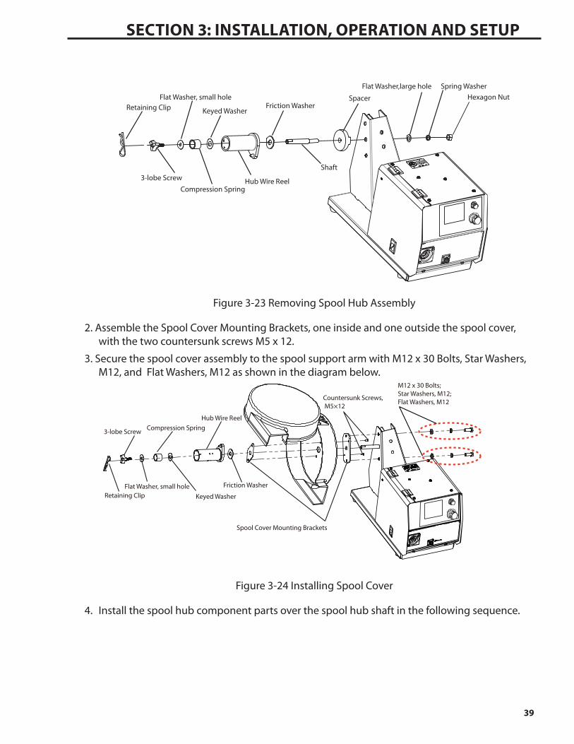
Spool cover is assembled in the following steps:1. Remove the spool hub assembly.
a. Remove the clip from the spool hub.
b. Unscrew the 3-lobe screw.
c. Remove the spool hub parts and the spacer in the following sequence. Note that the spacer is not required when fitting the spool cover.
39
SECTION 3: INSTALLATION, OpErATION AND SETUp
Hexagon NutSpring WasherFlat Washer,large hole
Spacer
Shaft
Friction Washer
Hub Wire Reel
Keyed Washer
Compression Spring
Flat Washer, small hole
3-lobe Screw
Retaining Clip
Figure 3-23 Removing Spool Hub Assembly
2. Assemble the Spool Cover Mounting Brackets, one inside and one outside the spool cover, with the two countersunk screws M5 x 12.
3. Secure the spool cover assembly to the spool support arm with M12 x 30 Bolts, Star Washers, M12, and Flat Washers, M12 as shown in the diagram below.
Spool Cover Mounting Brackets
Countersunk Screws, M5×12
Hub Wire Reel
Keyed Washer
Compression Spring
Flat Washer, small holeRetaining Clip
Friction Washer
M12 x 30 Bolts; Star Washers, M12; Flat Washers, M12
3-lobe Screw
Figure 3-24 Installing Spool Cover
4. Install the spool hub component parts over the spool hub shaft in the following sequence.

40
SECTION 3: installation, Operation and Setup
Friction Washer
Spool Hub
Keyed Washer
Spring
Flat Washer
3-lobe Screw
Retaining Clip
Figure 3-25 Spool Hub Assembly
! Warning
Fully tighten all fasteners.
Refer to the figures below for the assembled spool cover:
Figure 3-26a Assembled Spool Cover (door opened)

41
SECTION 3: INSTALLATION, OpErATION AND SETUp
Figure 3-26b Assembled Spool Cover
3.13 Installing Welding Wire Spool
! Warning
Fully tighten all fasteners.
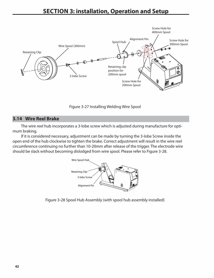
There are 3 holes on the spool hub support. The top screw hole is for installing a coil of 400mm (30kg) diameter. In this case a 30kg coil holder must be used. The 30kg coil holder is attached to the spool hub in the same way as for a 300mm spool, then the coil is placed over the 30kg coil holder & locked in place. The middle hole is for installing a spool of 300mm diameter (as shown in Figure 3-27). The bottom hole is for installing a spool of 200mm diameter. As delivered from the factory, the unit has the spool hub fitted into the middle (300mm spool) position.
1. Remove the retaining clip from the spool hub.
2. Install the wire spool over the spool hub, locating the hole in the spool, with the alignment pin on the spoolhub.
3. Insert the retaining clip back into the spool hub.
NOTEInstall the welding wire spool so that the wire feeds from the bottom of the spool into
the input wire guide.
42
SECTION 3: installation, Operation and Setup
Screw Hole for 400mm Spool
Screw Hole for 300mm Spool
Screw Hole for 200mm Spool
Retaining clip position for 200mm spool
Spool HubAlignment Pin
3-lobe Screw
Wire Spool (300mm)
Retaining Clip
Figure 3-27 Installing Welding Wire Spool
3.14 Wire Reel BrakeThe wire reel hub incorporates a 3-lobe screw which is adjusted during manufacture for opti-
mum braking. If it is considered necessary, adjustment can be made by turning the 3-lobe Screw inside the
open end of the hub clockwise to tighten the brake. Correct adjustment will result in the wire reel circumference continuing no further than 10-20mm after release of the trigger. The electrode wire should be slack without becoming dislodged from wire spool. Please refer to Figure 3-28.
3-lobe Screw
Retaining Clip
Wire Spool Hub
Alignment Pin
Figure 3-28 Spool Hub Assembly (with spool hub assembly installed)

43
SECTION 3: INSTALLATION, OpErATION AND SETUp
CAUTION
Overtension of brake will cause rapid wear of mechanical WIREFEED parts, overheating of electrical componentry and possibly an increased incidence of electrode wire Burnback into contact tip.
3.15 Inserting Wire into Feed Mechanism
WARNING
ELECTRIC SHOCK CAN KILL! Make certain the input power is disconnected from the power source before proceeding. Do not reattach the input power until told to do so in these instructions.
Warning
MOVING PARTS can cause injury.
1. Swing the Pressure Adjusting Knobs down and the two Pressure Roll Arms automatically spring up.
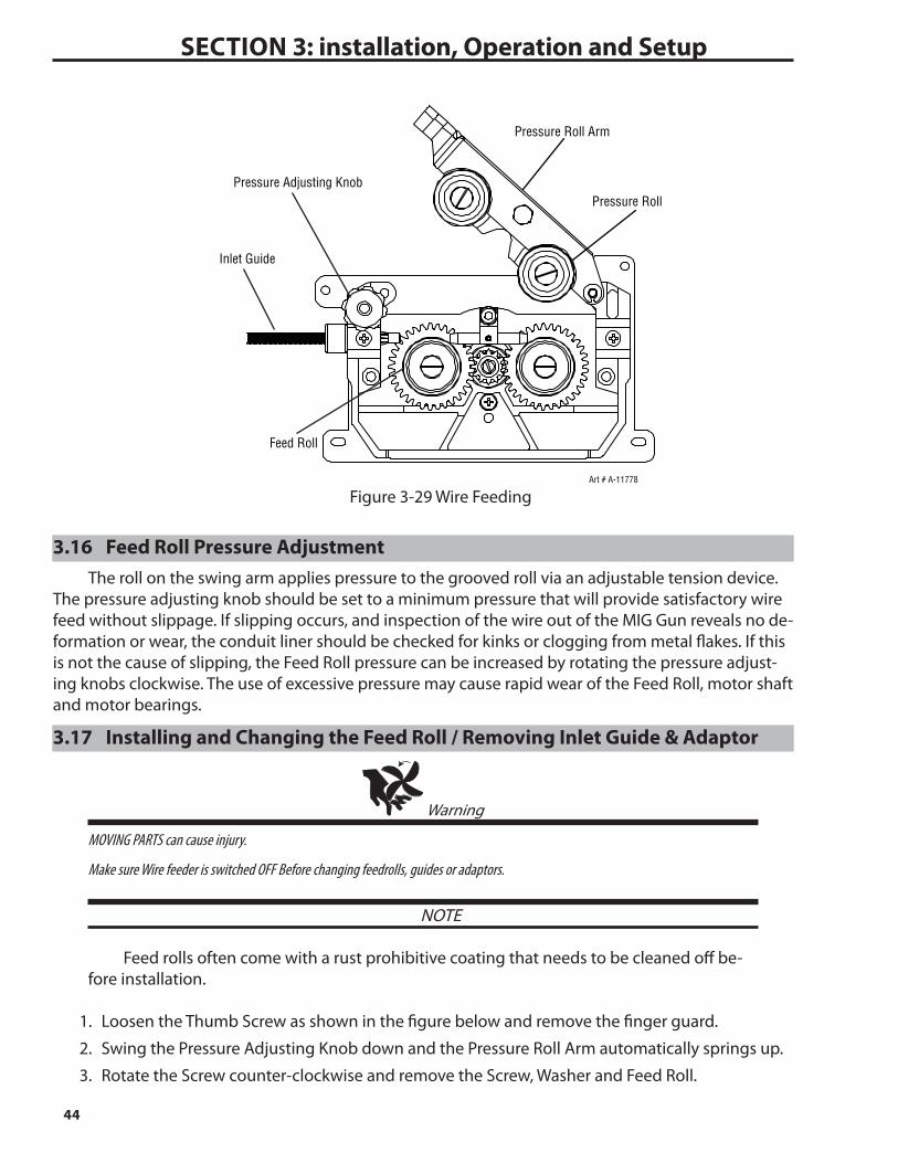
2. Make sure the end of the wire is free of any burrs and is straight. Pass the end of wire through the Inlet Guide and over the Feed Rolls. Make certain the proper groove is being used.
3. Pass the MIG wire over the feed roll groove and out past the MIG Torch Adaptor. Then fit the welding torch ensuring the MIG wire passes into the MIG Torch liner of the MIG Torch.
4. Lower the Pressure Roll Arms.
5. Swing the Pressure Adjusting Knobs back into place.
6. Use the Pressure Adjusting Knobs to create a “snug” condition. (Clockwise to tighten and Coun-ter Clockwise to loosen).
7. Turn ON the power supply. Set proper WFS and remove the tip from the welding torch. De-press INCH button until the wire reaches the top of welding torch. Tighten the tip again and finish inserting wire.
44
SECTION 3: installation, Operation and Setup
Pressure Roll Arm
Pressure Adjusting Knob
Inlet Guide
Feed Roll
Pressure Roll
Art # A-11778
Figure 3-29 Wire Feeding
3.16 Feed Roll Pressure AdjustmentThe roll on the swing arm applies pressure to the grooved roll via an adjustable tension device.
The pressure adjusting knob should be set to a minimum pressure that will provide satisfactory wire feed without slippage. If slipping occurs, and inspection of the wire out of the MIG Gun reveals no de-formation or wear, the conduit liner should be checked for kinks or clogging from metal flakes. If this is not the cause of slipping, the Feed Roll pressure can be increased by rotating the pressure adjust-ing knobs clockwise. The use of excessive pressure may cause rapid wear of the Feed Roll, motor shaft and motor bearings.
3.17 Installing and Changing the Feed Roll / Removing Inlet Guide & Adaptor
Warning
MOVING PARTS can cause injury.
Make sure Wire feeder is switched OFF Before changing feedrolls, guides or adaptors.
NOTE
Feed rolls often come with a rust prohibitive coating that needs to be cleaned off be-fore installation.
1. Loosen the Thumb Screw as shown in the figure below and remove the finger guard.
2. Swing the Pressure Adjusting Knob down and the Pressure Roll Arm automatically springs up.
3. Rotate the Screw counter-clockwise and remove the Screw, Washer and Feed Roll.
45
SECTION 3: INSTALLATION, OpErATION AND SETUp
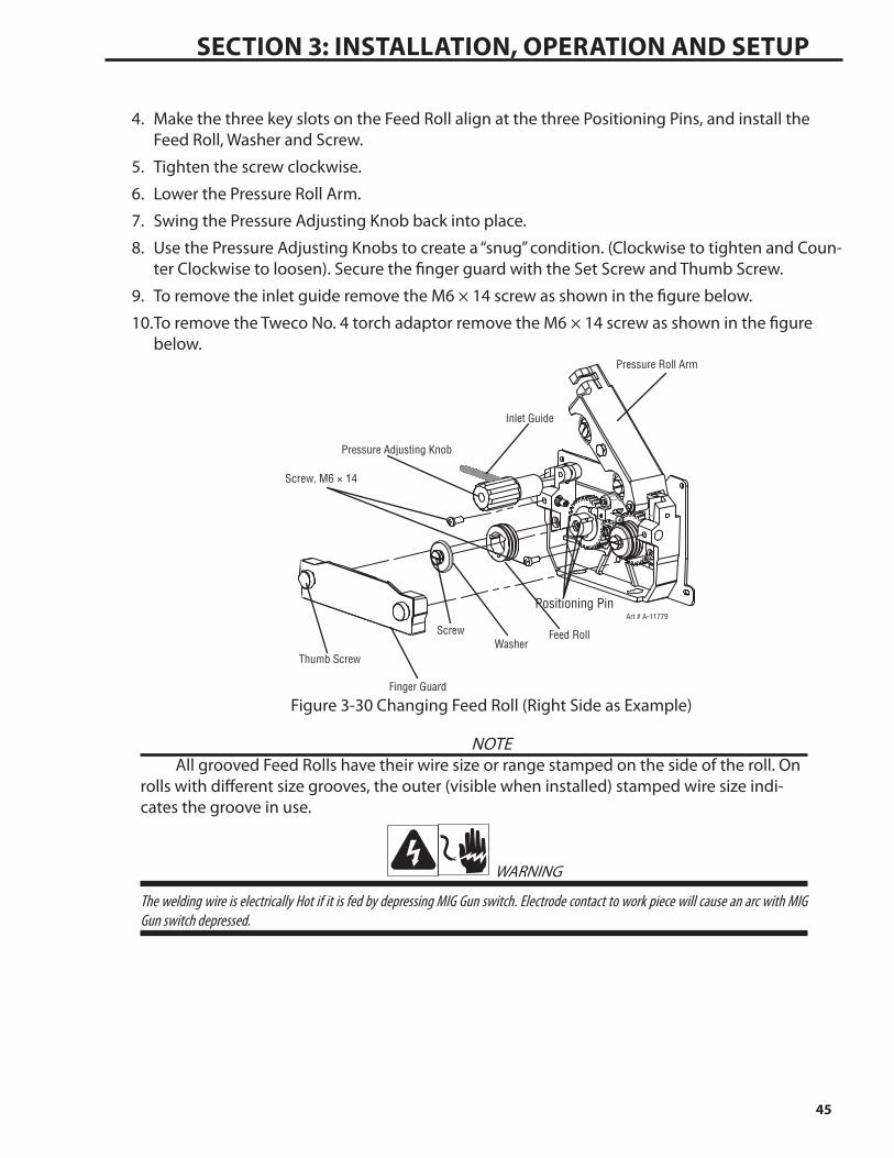
4. Make the three key slots on the Feed Roll align at the three Positioning Pins, and install the Feed Roll, Washer and Screw.
5. Tighten the screw clockwise.
6. Lower the Pressure Roll Arm.
7. Swing the Pressure Adjusting Knob back into place.
8. Use the Pressure Adjusting Knobs to create a “snug” condition. (Clockwise to tighten and Coun-ter Clockwise to loosen). Secure the finger guard with the Set Screw and Thumb Screw.
9. To remove the inlet guide remove the M6 × 14 screw as shown in the figure below.
10. To remove the Tweco No. 4 torch adaptor remove the M6 × 14 screw as shown in the figure below.
Finger Guard
Thumb Screw
ScrewWasher
Feed Roll
Screw, M6 × 14
Inlet Guide
Pressure Roll Arm
Pressure Adjusting Knob
Art # A-11779Positioning Pin
Figure 3-30 Changing Feed Roll (Right Side as Example)
NOTEAll grooved Feed Rolls have their wire size or range stamped on the side of the roll. On
rolls with different size grooves, the outer (visible when installed) stamped wire size indi-cates the groove in use.
WARNING
The welding wire is electrically Hot if it is fed by depressing MIG Gun switch. Electrode contact to work piece will cause an arc with MIG Gun switch depressed.

46
SECTION 3: installation, Operation and Setup
This page intentionally blank

4.01 Cleaning The UnitPeriodically, clean the inside of the wire feeder and feedhead assembly by using a vacuum
cleaner or clean, dry compressed air of not more than 25 psi (172 kPa) pressure. After cleaning the unit, check all electrical components for loose or faulty connections and correct if necessary.
4.02 Cleaning The Feed RollsClean the grooves on the lower feed roll frequently. This cleaning operation can be done by
using a small wire brush. Also, wipe off or clean the grooves on the upper bearing roll. After cleaning the feed rolls, tighten the feed roll retaining knobs accordingly.
4.03 System MaintenanceThe user has been given a visual tool in the feed monitor display. Use the feed monitor display
in determining when a new contact tip, liner, and/or wire guide is needed.
4.04 Troubleshooting GuideNOTE
Refer to the Connection Diagram in the Appendix chapter of this manual for graphical assistance in disassembling and troubleshooting the wire feeder.
ScopeThe troubleshooting guide is intended to be used by qualified service technicians. The trouble-
shooting guide contains information which can be used to diagnose and correct unsatisfactory op-eration or failure of the various components of the wire feeder. Each symptom of trouble is followed by a list of probable causes and the procedure necessary to correct the problem.Safety
To ensure safe operation and service, read this entire manual before attempting to service or repair this machine. The service technician may be asked to check voltage levels while the machine is turned ON. To assure safety, use care and follow all instructions accordingly.
4.05 MIG (GMAW/FCAW) Basic Welding TechniqueTwo different welding processes are covered in this section (GMAW and FCAW), with the inten-
tion of providing the very basic concepts in using the Mig mode of welding, where a MIG Torch is hand held, and the electrode (welding wire) is fed into a weld puddle, and the arc is shielded by an inert welding grade shielding gas or inert welding grade shielding gas mixture.
GAS METAL ARC WELDING (GMAW): This process, also known as MIG welding, CO2 welding, Mi-cro Wire Welding, short arc welding, dip transfer welding, wire welding etc., is an electric arc welding process which fuses together the parts to be welded by heating them with an arc between a solid continuous, consumable electrode and the work. Shielding is obtained from an externally supplied welding grade shielding gas or welding grade shielding gas mixture. The process is normally applied semi automatically; however the process may be operated automatically and can be machine oper-ated. The process can be used to weld thin and fairly thick steels, and some non-ferrous metals in all positions.
SECTION 4: SERVICE

48
SECTION 4: SErvICE
Art # A-8991_AB
Shielding Gas
Molten Weld Metal
Solidified Weld Metal
Nozzle
ElectrodeArc
Base Metal
GMAW Process
Figure 4-1 GMAW Process
FLUX CORED ARC WELDING (FCAW): This is an electric arc welding process which fuses together the parts to be welded by heating them with an arc between a continuous flux filled electrode wire and the work. Shielding is obtained through decomposition of the flux within the tubular wire. Additional shielding may or may not be obtained from an externally supplied gas or gas mixture. The process is normally applied semi automatically; however the process may be ap-plied automatically or by machine. It is commonly used to weld large diameter electrodes in the flat and horizontal position and small electrode diameters in all positions. The process is used to a lesser degree for welding stainless steel and for overlay work.
Art # A-08992_AB
Molten Slag
Nozzle(Optional)
FCAW Process
Flux CoredElectrode
Arc
Shielding Gas(Optional)
Slag
Molten Metal
Base MetalSolidified Weld Metal
Figure 4-2 FCAW Process
Position of MIG TorchThe angle of MIG Torch to the weld has an effect on the width of the weld.
Push Vertical Drag/Pull
Art # A-07185_AB
Figure 4-3 Position of MIG Torch
The MIG Torch should be held at an angle to the weld joint. (See Secondary Adjustment Variables below)
Hold the MIG Torch so that the welding seam is viewed at all times. Always wear the welding helmet with proper filter lenses and use the proper safety equipment.
49
SECTION 4: SErvICE
CAUTION
Do NOT pull the MIG Torch back when the arc is established. This will create excessive wire extension (stick-out) and make a very poor weld.The electrode wire is not energized until the MIG Torch trigger switch is depressed. The wire
may therefore be placed on the seam or joint prior to lowering the helmet.
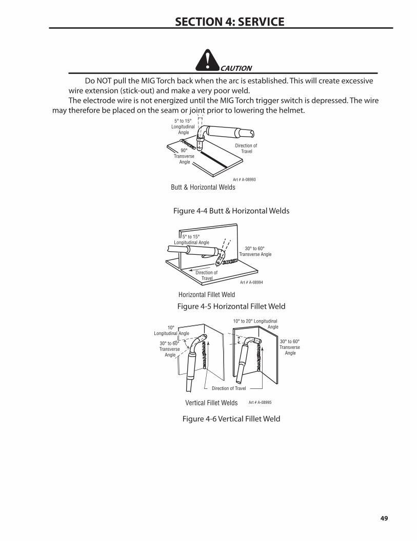
Butt & Horizontal Welds
Direction of Travel
5° to 15° Longitudinal
Angle
90° Transverse
Angle
Art # A-08993
Figure 4-4 Butt & Horizontal Welds
Horizontal Fillet Weld
Direction of Travel
5° to 15° Longitudinal Angle
30° to 60° Transverse Angle
Art # A-08994
Figure 4-5 Horizontal Fillet Weld
Vertical Fillet Welds Art # A-08995
30° to 60° Transverse
Angle
30° to 60° Transverse
Angle
Direction of Travel
10° Longitudinal Angle
10° to 20° Longitudinal Angle
Figure 4-6 Vertical Fillet Weld
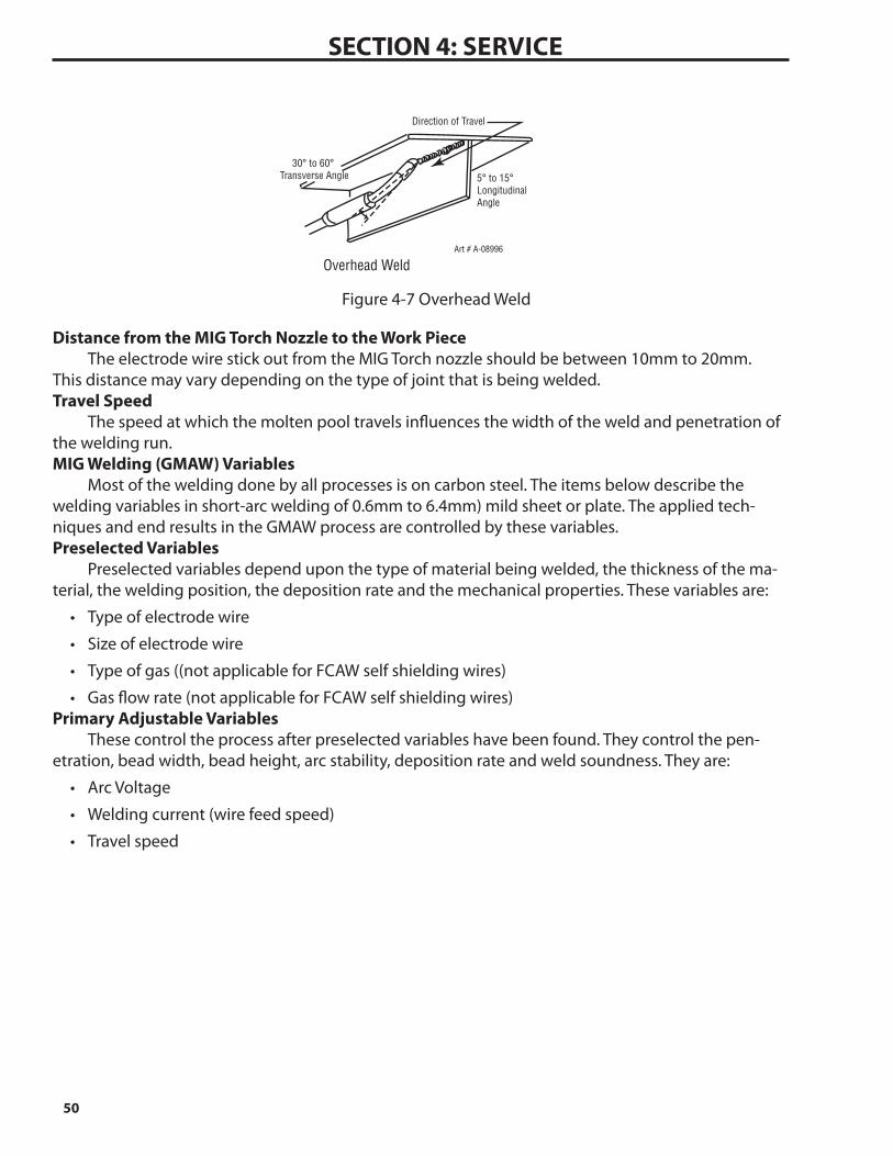
50
SECTION 4: SErvICE
Overhead WeldArt # A-08996
30° to 60° Transverse Angle
Direction of Travel
5° to 15° Longitudinal Angle
Figure 4-7 Overhead Weld
Distance from the MIG Torch Nozzle to the Work PieceThe electrode wire stick out from the MIG Torch nozzle should be between 10mm to 20mm.
This distance may vary depending on the type of joint that is being welded.Travel Speed
The speed at which the molten pool travels influences the width of the weld and penetration of the welding run.MIG Welding (GMAW) Variables
Most of the welding done by all processes is on carbon steel. The items below describe the welding variables in short-arc welding of 0.6mm to 6.4mm) mild sheet or plate. The applied tech-niques and end results in the GMAW process are controlled by these variables.Preselected Variables
Preselected variables depend upon the type of material being welded, the thickness of the ma-terial, the welding position, the deposition rate and the mechanical properties. These variables are:
• Typeofelectrodewire
• Sizeofelectrodewire
• Typeofgas((notapplicableforFCAWselfshieldingwires)
• Gasflowrate(notapplicableforFCAWselfshieldingwires)Primary Adjustable Variables
These control the process after preselected variables have been found. They control the pen-etration, bead width, bead height, arc stability, deposition rate and weld soundness. They are:
• ArcVoltage
• Weldingcurrent(wirefeedspeed)
• Travelspeed
51
SECTION 4: SErvICE
Secondary Adjustable VariablesThese variables cause changes in primary adjustable variables which in turn cause the desired
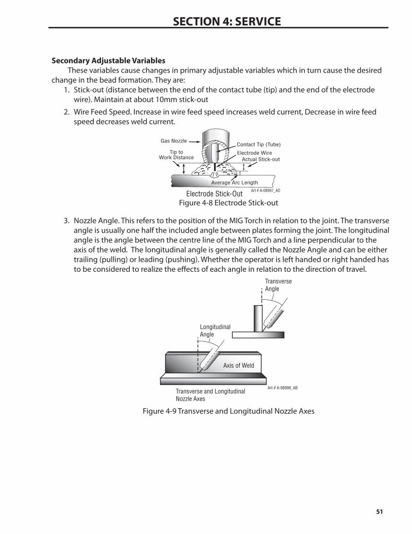
change in the bead formation. They are:1. Stick-out (distance between the end of the contact tube (tip) and the end of the electrode
wire). Maintain at about 10mm stick-out
2. Wire Feed Speed. Increase in wire feed speed increases weld current, Decrease in wire feed speed decreases weld current.
Art # A-08997_AD
Gas Nozzle
Electrode Wire
Average Arc Length
Electrode Stick-Out
Tip toWork Distance Actual Stick-out
Contact Tip (Tube)
Figure 4-8 Electrode Stick-out
3. Nozzle Angle. This refers to the position of the MIG Torch in relation to the joint. The transverse angle is usually one half the included angle between plates forming the joint. The longitudinal angle is the angle between the centre line of the MIG Torch and a line perpendicular to the axis of the weld. The longitudinal angle is generally called the Nozzle Angle and can be either trailing (pulling) or leading (pushing). Whether the operator is left handed or right handed has to be considered to realize the effects of each angle in relation to the direction of travel.
Transverse and LongitudinalNozzle Axes
Art # A-08998_AB
LongitudinalAngle
Axis of Weld
TransverseAngle
Figure 4-9 Transverse and Longitudinal Nozzle Axes

52
SECTION 4: SErvICE
Art # A-08999_ACNozzle Angle, Right Handed Operator
Direction of Gun Travel
Leading or “Pushing”Angle
(Forward Pointing)
Trailing or “Pulling”Angle
(Backward Pointing)
90°
Figure 4-10 Nozzle Angle, Right Handed Operator
Establishing the Arc and Making Weld BeadsBefore attempting to weld on a finished piece of work, it is recommended that practice welds be
made on a sample metal of the same material as that of the finished piece.The easiest welding procedure for the beginner to experiment with MIG welding is the flat posi-
tion. The equipment is capable of flat, vertical and overhead positions.For practicing MIG welding, secure some pieces of 1.5mm or 2.0mm mild steel plate 150 x
150mm. Use 0.8mm flux cored gasless wire or a solid wire with shielding gas.Setting of the Power Source
Power source and Wire feeder setting requires some practice by the operator, as the welding plant has two control settings that have to balance. These are the Wirespeed control and the weld-ing Voltage Control. The welding current is determined by the Wirespeed control, the current will increase with increased Wirespeed, resulting in a shorter arc. Less wire speed will reduce the current and lengthen the arc. Increasing the welding voltage hardly alters the current level, but lengthens the arc. By decreasing the voltage, a shorter arc is obtained with a little change in current level.
When changing to a different electrode wire diameter, different control settings are required. A thinner electrode wire needs more Wirespeed to achieve the same current level.
A satisfactory weld cannot be obtained if the Wirespeed and Voltage settings are not adjusted to suit the electrode wire diameter and the dimensions of the work piece.
If the Wirespeed is too high for the welding voltage, “stubbing” will occur as the wire dips into the molten pool and does not melt. Welding in these conditions normally produces a poor weld due to lack of fusion. If, however, the welding voltage is too high, large drops will form on the end of the wire, causing spatter. The correct setting of voltage and Wirespeed can be seen in the shape of the weld deposit and heard by a smooth regular arc sound. Refer to the Weld Guide located on the inside of the wirefeed compartment door for setup information.Electrode Wire Size Selection
The choice of Electrode wire size and shielding gas used depends on the following
• Thickness of the metal to be welded• Typeofjoint• CapacityofthewirefeedunitandPowerSource• Theamountofpenetrationrequired• Thedepositionraterequired• Thebeadprofiledesired• Thepositionofwelding• Costofthewire
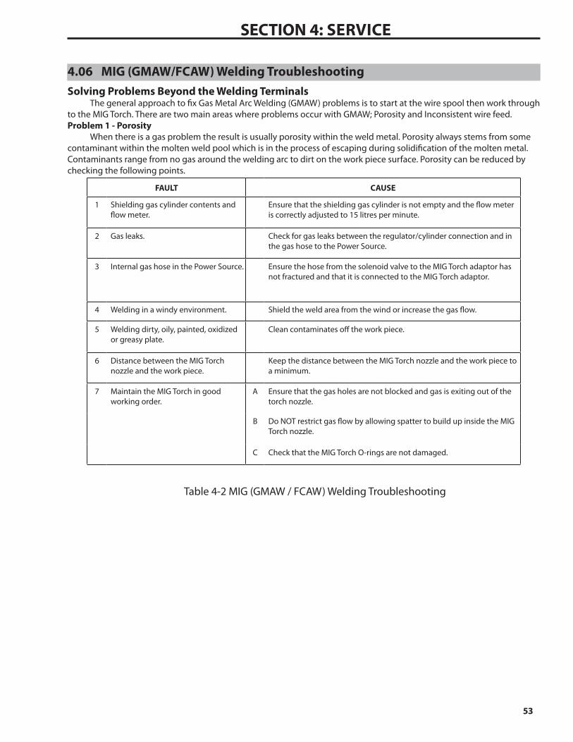
53
SECTION 4: SErvICE
4.06 MIG (GMAW/FCAW) Welding TroubleshootingSolving Problems Beyond the Welding Terminals
The general approach to fix Gas Metal Arc Welding (GMAW) problems is to start at the wire spool then work through to the MIG Torch. There are two main areas where problems occur with GMAW; Porosity and Inconsistent wire feed.Problem 1 - Porosity
When there is a gas problem the result is usually porosity within the weld metal. Porosity always stems from some contaminant within the molten weld pool which is in the process of escaping during solidification of the molten metal. Contaminants range from no gas around the welding arc to dirt on the work piece surface. Porosity can be reduced by checking the following points.
FAULT CAUSE
1 Shielding gas cylinder contents and flow meter.
Ensure that the shielding gas cylinder is not empty and the flow meter is correctly adjusted to 15 litres per minute.
2 Gas leaks. Check for gas leaks between the regulator/cylinder connection and in the gas hose to the Power Source.
3 Internal gas hose in the Power Source. Ensure the hose from the solenoid valve to the MIG Torch adaptor has not fractured and that it is connected to the MIG Torch adaptor.
4 Welding in a windy environment. Shield the weld area from the wind or increase the gas flow.
5 Welding dirty, oily, painted, oxidized or greasy plate.
Clean contaminates off the work piece.
6 Distance between the MIG Torch nozzle and the work piece.
Keep the distance between the MIG Torch nozzle and the work piece to a minimum.
7 Maintain the MIG Torch in good working order.
A Ensure that the gas holes are not blocked and gas is exiting out of the torch nozzle.
B Do NOT restrict gas flow by allowing spatter to build up inside the MIG Torch nozzle.
C Check that the MIG Torch O-rings are not damaged.
Table 4-2 MIG (GMAW / FCAW) Welding Troubleshooting

54
SECTION 4: SErvICE
Problem 2 - Inconsistent Wire Feed
! WARNING
Disengage the feed roll when testing for gas flow by ear.
Wire feeding problems can be reduced by checking the following points.
FAULT CAUSE
1 Feed roller driven by motor in the cabinet slipped.
Wire spool brake is too tight.
2 Wire spool unwound and tangled. Wire spool brake is too loose.
3 Worn or incorrect feed roller size A Use a feed roller matched to the size you are welding.
B Replace feed roller if worn.
4 Wire rubbed against the misaligned guides and reduced wire feed ability.
Misalignment of inlet/outlet guides
5 Liner blocked with swarf A Increased amounts of swarf are produced by the wire passing through the feed roller when excessive pressure is applied to the pressure roller adjuster.
B Swarf can also be produced by the wire passing through an incorrect feed roller groove shape or size.
C Swarf is fed into the conduit liner where it accumulates thus reducing wire feed ability.
6 Incorrect or worn contact tip A The contact tip transfers the weld current to the electrode wire. If the hole in the contact tip is too large then arcing may occur inside the contact tip resulting in the wire jamming in the contact tip
B When using soft wire such as aluminium it may become jammed in the contact tip due to expansion of the wire when heated. A contact tip designed for soft wires should be used.
7 Poor work lead contact to work piece If the work lead has a poor electrical contact to the work piece then the connection point will heat up and result in a reduction of power at the arc.
8 Bent liner This will cause friction between the wire and the liner thus reducing wire feed ability
Table 4-3 Wire Feeding Problems

55
SECTION 4: SErvICE
Basic MIG (GMAW/FCAW) Welding Troubleshooting
FAULT CAUSE REMEDY1 Undercut A Welding arc voltage too high. A Decrease voltage or increase the wire feed speed.
B Incorrect MIG Torch angle B Adjust angle.
C Excessive heat input C Increase the MIG Torch travel speed and/or decrease welding current by decreasing the voltage or decreasing the wire feed speed.
2 Lack of penetration A Welding current too low A Increase welding current by increasing wire feed speed and increasing voltage.
B Joint preparation too narrow or gap too tight
B Increase joint angle or gap.
C Shielding gas incorrect C Change to a gas which gives higher penetration.
3 Lack of fusion Voltage too low Increase voltage.
4 Excessive spatter A Voltage too high A Decrease voltage or increase the wirespeed control.
B Voltage too low B Increase the voltage or decrease wirespeed.
5 Irregular weld shape A Incorrect voltage and current settings. Convex, voltage too low. Concave, voltage too high.
A Adjust voltage and current by adjusting the voltage control and the wirespeed control.
B Wire is wandering. B Replace contact tip.
C Incorrect shielding gas C Check shielding gas.
D Insufficient or excessive heat input
D Adjust the wirespeed control or the voltage control.
6 Weld cracking A Weld beads too small A Decrease travel speed
B Weld penetration narrow and deep
B Reduce current and voltage and increase MIG Torch travel speed or select a lower penetration shielding gas.
C Excessive weld stresses C Increase weld metal strength or revise design
D Excessive voltage D Decrease voltage.
E Cooling rate too fast E Slow the cooling rate by preheating part to be welded or cool slowly.
7 Cold weld puddle A Loose welding cable connection. A Check all welding cable connections.
B Low primary voltage B Contact supply authority.
C Fault in power source C Have an Accredited ESAB Service Provider test then replace the faulty component.
8 Arc does not have a crisp sound that short arc exhibits when the wirefeed speed and voltage are adjusted correctly.
The MIG Torch has been connected to the wrong voltage polarity on the front panel.
Connect the MIG torch to the positive (+) welding terminal for solid wires and gas shielded flux cored wires. Refer to the electrode wire manufacturer for the correct polarity.
Table 4-4 GMAW (MIG) Welding Problems

56
SECTION 4: SErvICE
4.07 Troubleshooting
WARNING
ELECTRIC SHOCK can kill.
Follow all safety precautions.Do not touch live electrical parts.Turn OFF input power before servicing the machine unless otherwise noted.Only qualified technicians are to service the machine.
WARNINGS
PC boards and their components are static sensitive devices.Use static proof bags.Use grounded wrist strap.Only qualified personnel should test or handle these devices.Use only genuine replacement parts.
FAULT CAUSE REMEDY
1 Displays are not lit and welding arc cannot be established.
A B
C D E
Switch on rear panel of Wire feeder is not turned ON. Power Source is not turned ON. 10 Pin control cable is not connected between the power source and Wire feeder.
Circuit Breaker on power source is tripped (pops out).
Faulty 10 Pin control cable connecting power source and Wire feeder.
A B
C D E
Turn switch on rear panel of Wire feeder to ON. Turn power source ON and ensure it is in the correct mode of operation.
Connect 10 Pin control cable between the power source and Wire feeder.
Reset circuit breaker by pushing it in. If it fails to reset have an Accredited ESAB Service Provider investigate the fault.
Repair or replace the 10 Pin control cable.
2 Displays are not lit but welding arc can be established.
Faulty Display on display PCB. Have an Accredited ESAB Service Provider investigate the fault.
3 Displays are lit but when the torch trigger switch is depressed nothing happens.
A B
Torch trigger switch leads are disconnected. Faulty trigger switch/lead.
A B
Re connect Torch trigger switch leads.
Repair or replace torch trigger lead.
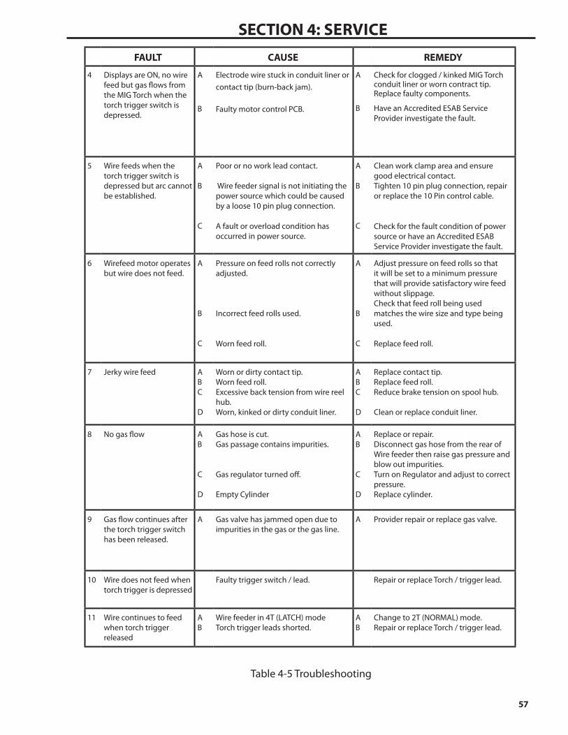
57
SECTION 4: SErvICEFAULT CAUSE REMEDY
4 Displays are ON, no wire feed but gas flows from the MIG Torch when the torch trigger switch is depressed.
A
B
Electrode wire stuck in conduit liner or contact tip (burn-back jam). Faulty motor control PCB.
A
B
Check for clogged / kinked MIG Torch conduit liner or worn contract tip. Replace faulty components.
Have an Accredited ESAB Service Provider investigate the fault.
5 Wire feeds when the torch trigger switch is depressed but arc cannot be established.
A B C
Poor or no work lead contact. Wire feeder signal is not initiating the power source which could be caused by a loose 10 pin plug connection.
A fault or overload condition has occurred in power source.
A B C
Clean work clamp area and ensure good electrical contact. Tighten 10 pin plug connection, repair or replace the 10 Pin control cable.
Check for the fault condition of power source or have an Accredited ESAB Service Provider investigate the fault.
6 Wirefeed motor operates but wire does not feed.
A B C
Pressure on feed rolls not correctly adjusted. Incorrect feed rolls used. Worn feed roll.
A B C
Adjust pressure on feed rolls so that it will be set to a minimum pressure that will provide satisfactory wire feed without slippage. Check that feed roll being used matches the wire size and type being used.
Replace feed roll.
7 Jerky wire feed A B C D
Worn or dirty contact tip. Worn feed roll. Excessive back tension from wire reel hub. Worn, kinked or dirty conduit liner.
A B C D
Replace contact tip. Replace feed roll. Reduce brake tension on spool hub. Clean or replace conduit liner.
8 No gas flow A B C D
Gas hose is cut. Gas passage contains impurities. Gas regulator turned off. Empty Cylinder
A B C D
Replace or repair. Disconnect gas hose from the rear of Wire feeder then raise gas pressure and blow out impurities. Turn on Regulator and adjust to correct pressure. Replace cylinder.
9 Gas flow continues after the torch trigger switch has been released.
A
Gas valve has jammed open due to impurities in the gas or the gas line.
A
Provider repair or replace gas valve.
10 Wire does not feed when torch trigger is depressed
Faulty trigger switch / lead. Repair or replace Torch / trigger lead.
11 Wire continues to feed when torch trigger released
A B
Wire feeder in 4T (LATCH) mode Torch trigger leads shorted.
A B
Change to 2T (NORMAL) mode. Repair or replace Torch / trigger lead.
Table 4-5 Troubleshooting

58
SECTION 4: SErvICE
This page intentionally blank

SECTION 5: PARTS LIST
5.01 Equipment IdentificationAll identification numbers as described in the Introduction Chapter must be furnished when
ordering parts or making inquiries. This information is found on the nameplate attached to the equipment. Be sure to include any dash numbers following the Specification or Assembly num-bers.
PART NUMBER: 0558102233/0558102234
5.02 How To Use This Parts ListThe Parts List is a combination of an illustration (Figure Number) and a corresponding list of
parts which contains a breakdown of the equipment into assemblies, subassemblies, and detail parts. All user-serviceable parts are listed except for commercially available hardware, bulk items such as wire, cable, sleeving, tubing, etc. The part descriptions may be indented to show part relationships.
To determine the part number, description, quantity, or application of an item, locate the item in question from the illustration and refer to that item number in the corresponding Parts List.
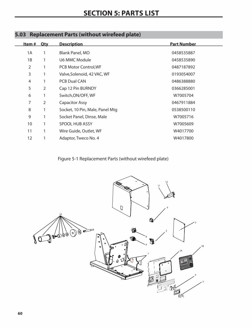
60
SECTION 5: ParTS LIST
5.03 Replacement Parts (without wirefeed plate)
Item # Qty Description Part Number
1A 1 Blank Panel, MO 0458535887
1B 1 U6 MMC Module 0458535890
2 1 PCB Motor Control,WF 0487187892
3 1 Valve,Solenoid, 42 VAC, WF 0193054007
4 1 PCB Dual CAN 0486388880
5 2 Cap 12 Pin BURNDY 0366285001
6 1 Switch,ON/OFF, WF W7005704
7 2 Capacitor Assy 0467911884
8 1 Socket, 10 Pin, Male, Panel Mtg 0538500110
9 1 Socket Panel, Dinse, Male W7005716
10 1 SPOOL HUB ASSY W7005609
11 1 Wire Guide, Outlet, WF W4017700
12 1 Adaptor, Tweco No. 4 W4017800
Figure 5-1 Replacement Parts (without wirefeed plate)
2
6
3
5
8
9
10
12
11
1B
1A
4
7

61
SECTION 5: ParTS LIST
5.04 Replacement Parts- Wirefeed Plate
Item # Qty Description Part Number
14 1 Motor, 42V, WF W7006201
15 1 Wire Drive Assy, 4R, WF W7006200
16 1 Wire Guide, Inlet, WF W7006206
17 1 Wire Guide, Centre, WF W7006202
18 2 Feed Roll Refer to Subsection 2.09
19 2 Idler Gear, 4R W7006203
20 1 Drive Gear, 4R W7006204
21 1 Finger Guard W7006205
15 1920
1617
14
18
21
Art # A-11786
Figure 5-2 Replacement Parts- Wirefeed Plate
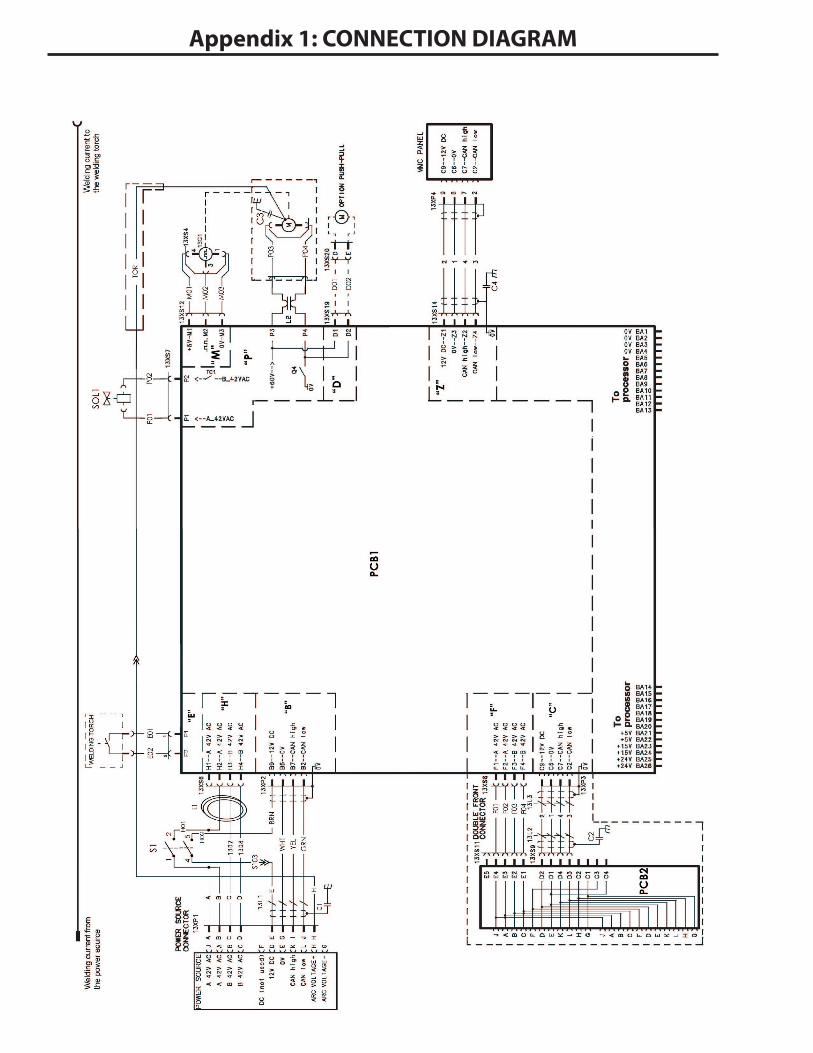
Appendix 1: CONNECTION DIAGRAM

This page intentionally blank

A. CUSTOMER SERVICE QUESTIONS: Telephone: (800)362-7080 / Fax: (800) 634-7548 Hours: 8:00 AM to 7:00 PM EST Order Entry Product Availability Pricing Order Information Returns
B. ENGINEERING SERVICE: Telephone: (843) 664-4416 / Fax : (800) 446-5693 Hours: 7:30 AM to 5:00 PM EST Warranty Returns Authorized Repair Stations Welding Equipment Troubleshooting
C. TECHNICAL SERVICE: Telephone: (800) ESAB-123/ Fax: (843) 664-4452 Hours: 8:00 AM to 5:00 PM EST Part Numbers Technical Applications Specifications Equipment Recommendations
D. LITERATURE REQUESTS: Telephone: (843) 664-5562 / Fax: (843) 664-5548 Hours: 7:30 AM to 4:00 PM EST
E. WELDING EQUIPMENT REPAIRS: Telephone: (843) 664-4487 / Fax: (843) 664-5557 Hours: 7:30 AM to 3:30 PM EST Repair Estimates Repair Status
F. WELDING EQUIPMENT TRAINING Telephone: (843)664-4428 / Fax: (843) 679-5864 Hours: 7:30 AM to 4:00 PM EST Training School Information and Registrations
G. WELDING PROCESS ASSISTANCE: Telephone: (800) ESAB-123 Hours: 7:30 AM to 4:00 PM EST
H. TECHNICAL ASST. CONSUMABLES: Telephone : (800) 933-7070 Hours: 7:30 AM to 5:00 PM EST
IF YOU DO NOT KNOW WHOM TO CALL
Telephone: (800) ESAB-123 Fax: (843) 664-4462
Hours: 7:30 AM to 5:00 PM ESTor
visit us on the web at http://www.esabna.comThe ESAB web site offers
Comprehensive Product InformationMaterial Safety Data Sheets
Warranty RegistrationInstruction Literature Download Library
Distributor LocatorGlobal Company Information
Press ReleasesCustomer Feedback & Support
ESAB Welding & Cutting Products, Florence, SCCOMMUNICATION GUIDE - CUSTOMER SERVICES


