Obtaining desirable tower performance requires the proper handling of liquid and vapor entering the column. The types of feeds or inlets into a column can generally be classified into four major categories: • Liquid only (contains less than 1% vapor by volume ) • Mixed liquid and vapor, flashing or suppressed flash • Vapor only • Reboiler returns The selection criteria for each category of feed device is unique. Liquid-Only Feeds Among the factors Koch-Glitsch consid- ers in designing a liquid feed device are; type of distributor, expected distributor performance, flow rate, operating range, degree of sub-cooled liquid and whether mixing with overhead liquid is required. When the feed or reflux liquid is signifi- cantly sub-cooled, a specially designed feed arrangement may be required. A liquid with a wide temperature gradient, even if properly distributed to a packed bed, can induce mal-distribu- tion due to uneven condensation. The feed arrangement for these condi- tions depends on the distributor type. Please consult a Koch-Glitsch technical representative for recommendations. Liquid-Vapor and Flashing Feeds For mixed liquid-vapor or flashing feed devices above a distributor, the selection depends on the distributor type, liquid and vapor flow rates, turndown, column height needed for disengagement and vapor distribution as well as the degree of mixing of the inlet liquid with the overhead liquid. In all cases, separating the vapor and the liquid phases is a pri- mary concern. In some cases the requirements for additional pre-distribu- tion may alter certain distributor designs. Vapor-Only Feeds Two factors must be considered in choosing the proper device for a vapor only feed. 1. The kinetic energy of the inlet vapor must be considered in relation to the pressure drop in the packed bed, the feed nozzle arrangement and the tower separation requirements. 2. If there is a gross mismatch in the composition and/or temperature between the inlet vapor stream and bulk vapor flow, mixing of the two vapors optimizes the performance of the packing above. Specific equipment for vapor distribution may not be required if sufficient column height is available for equalization or if the pressure drop in the packed bed is sufficient to provide proper vapor distri- bution. Reboiler Returns To determine the need for and the type of device required for a reboiler return, the first step is to consider the condition of the stream and its kinetic energy. For vapor-only returns, the kinetic energy of the inlet vapor must be considered in relation to the pressure drop in the packed bed, the feed nozzle size and arrangement, as well as the tower separation requirements. For a mixed liquid-vapor or suppressed flash reboiler return stream, the selec- tion of the device depends on flow rate, ratio of liquid and vapor flow, flow regime, nozzle size and arrangement, column height needed for vapor disen- gagement and the tower separation requirements. CFD Modeling Good vapor distribution is essential to achieve superior separation efficiency. Particularly in refinery towers, poor vapor distribution can be a major source of coke formation resulting in frequent unit shutdowns. Koch-Glitsch uses modern Computational Fluid Dynamics (CFD) modeling technology to analyze the per- formance of existing equipment and to develop new improved designs. This involves computer modeling of the 3- dimensional configuration of the column internals to provide detailed predictions of fluid flow (velocity profiles, etc). A commercially available CFD software package is used in conjunction with expertise developed by Koch-Glitsch to analyze vapor and liquid distributors as well as packing performance. Koch-Glitsch offers CFD services for the following tasks: • Development and optimization of new mass transfer equipment • Troubleshooting or analysis of existing equipment • Confirmation of equipment designs prior to fabrication and installation Feed Devices 18
Transcript
Obtaining desirable tower performancerequires the proper handling of liquidand vapor entering the column. Thetypes of feeds or inlets into a columncan generally be classified into fourmajor categories:
• Liquid only (contains less than 1% vapor by volume )
• Mixed liquid and vapor, flashing or suppressed flash
• Vapor only • Reboiler returns
The selection criteria for each categoryof feed device is unique.
Liquid-Only Feeds
Among the factors Koch-Glitsch consid-ers in designing a liquid feed device are;type of distributor, expected distributorperformance, flow rate, operating range,degree of sub-cooled liquid and whethermixing with overhead liquid is required.
When the feed or reflux liquid is signifi-cantly sub-cooled, a specially designedfeed arrangement may be required.A liquid with a wide temperature gradient, even if properly distributed to a packed bed, can induce mal-distribu-tion due to uneven condensation.
The feed arrangement for these condi-tions depends on the distributor type.Please consult a Koch-Glitsch technicalrepresentative for recommendations.
Liquid-Vapor and Flashing Feeds
For mixed liquid-vapor or flashing feeddevices above a distributor, the selectiondepends on the distributor type, liquidand vapor flow rates, turndown, columnheight needed for disengagement andvapor distribution as well as the degreeof mixing of the inlet liquid with theoverhead liquid. In all cases, separatingthe vapor and the liquid phases is a pri-mary concern. In some cases therequirements for additional pre-distribu-tion may alter certain distributor designs.
Vapor-Only Feeds
Two factors must be considered inchoosing the proper device for a vaporonly feed.
1. The kinetic energy of the inlet vapor must be considered in relation to the pressure drop in the packed bed, the feed nozzle arrangement and the tower separation requirements.
2. If there is a gross mismatch in the composition and/or temperature between the inlet vapor stream and bulk vapor flow, mixing of the two vapors optimizes the performance of the packing above.
Specific equipment for vapor distributionmay not be required if sufficient columnheight is available for equalization or ifthe pressure drop in the packed bed issufficient to provide proper vapor distri-bution.
Reboiler Returns
To determine the need for and the typeof device required for a reboiler return,the first step is to consider the conditionof the stream and its kinetic energy.
For vapor-only returns, the kinetic energy of the inlet vapor must be considered in relation to the pressuredrop in the packed bed, the feed nozzlesize and arrangement, as well as thetower separation requirements.
For a mixed liquid-vapor or suppressedflash reboiler return stream, the selec-tion of the device depends on flow rate,ratio of liquid and vapor flow, flowregime, nozzle size and arrangement,column height needed for vapor disen-gagement and the tower separationrequirements.
CFD Modeling
Good vapor distribution is essential toachieve superior separation efficiency.Particularly in refinery towers, poor vapordistribution can be a major source ofcoke formation resulting in frequent unitshutdowns. Koch-Glitsch uses modernComputational Fluid Dynamics (CFD)modeling technology to analyze the per-formance of existing equipment and todevelop new improved designs. Thisinvolves computer modeling of the 3-dimensional configuration of the columninternals to provide detailed predictionsof fluid flow (velocity profiles, etc). Acommercially available CFD softwarepackage is used in conjunction withexpertise developed by Koch-Glitsch toanalyze vapor and liquid distributors aswell as packing performance.
Koch-Glitsch offers CFD services for thefollowing tasks:
• Development and optimization of new mass transfer equipment
• Troubleshooting or analysis of existing equipment
• Confirmation of equipment designs prior to fabrication and installation
Feed Devices
18
straub2r
KG_with_R
The Model 119 feed pipe is attachedto an internal column flange with fur-ther support by tower wall clips.
Branched piping is flanged as the standard, although, piping may havethreaded connections for pipe diame-ters less than 4 in. [100 mm]. Forlarge diameter headers, where man-way access is limiting, field weldingmay be required.
• Bayonet-style construction for limited applications
• All-flanged construction• Special design for subcooled feed
� Feed to INTALOX high performance distributors
The Model 119 liquid only feed pipe is used whenliquid is fed from outside the column onto a Koch-Glitsch INTALOX high performance distributor orredistributor. The incoming flow must contain lessthan 1% vapor by volume.
The Model 119 feed pipe is a metered piping systemconsisting of one or more headers in conjunctionwith lateral branches, downpipes, and/or pre-distri-bution channels or parting boxes that feed directlyto an INTALOX distributor. It is limited in turndownto a 2 : 1 ratio. The Model 119 feed pipe metersflow to one or more appropriate feed areas, match-ing the hydraulic requirements of the distributor.Excessive turbulence and horizontal flow velocity inthe distributor are eliminated.
Model 119 INTALOX® High Performance Liquid Only Feed Pipe
The Model 719 feed pipe is attachedto an internal column flange with fur-ther support by tower wall clips.
Piping may have threaded connec-tions for pipe diameters less than 4 in. [100 mm]. For large diameterheaders, where manway access is limiting, field welding may berequired.
• Bayonet-style construction• All-flanged construction
� Feed to traditional liquid distributors
The Model 719 liquid only feed pipe is used whenliquid is fed from outside the column onto a tradi-tional distributor or redistributor. The incoming flowmust contain less than 1% vapor by volume.
The Model 719 feed pipe is a piping system consist-ing of one or more headers in conjunction withdownpipes, pre-distribution channels or partingboxes that feeds directly to a traditional style distributor. The standard turndown ratio is 2.5 : 1
Model 719 Liquid Only Feed Pipe
19
Construction Details Design Options
Construction Details Design Options
straub2r
KG_with_R
For column diameters under 22 in.[530 mm], the Model 705 feed cham-ber is constructed in one piece. Forlarger diameters the chamber is con-structed in multiple pieces.
For inlet pipe sizes less than 4 in.[100 mm], the Model 705 feed cham-ber attaches to a threaded, bayonetstyle pipe (supplied by others). Inletsizes 4 in. [100 mm] and largerare attached with a flange asstandard.
• Supply of bayonet inlet
� Diameters up to 48 in. [1200 mm]� Handles most two-phase feeds
The Model 705 is a two-phase feed device that isattached to a radial inlet. By using centrifugal force,the vapor exits the top of the chamber and the liquid is conducted out the bottom to a distributoror pre-distributor located below.
One or more Model 705 chambers may be used in larger diameter columns if the flow rates are suitable.
Model 705 Flashing Feed Chamber Construction Details Design Options
The Model 745 feed pipe is connect-ed to an internal column flange andfurther supported by a wall clip. Theflash trough bolts to clips, seats orbeams depending upon location andsize.
The inlet pipe flange is gasketed,while the need for gasketing of theflash trough depends on the typedevice below it.
• Bayonet type feed pipe• Vapor hood
� Diameters greater than 36 in. [900 mm]� Feed device separates liquid and vapor of
flashing inlet streams
The Model 745 feed pipe is used to handle flashinginlet streams by separating the phases. The liquidimpinges on an angled baffle trough, promoting dis-engagement of the liquid and vapor phases. Thevapor exits above and the liquid is directed down-ward. The liquid may be sent directly to a distribu-tor, a pre-distributor or to a collector locatedbetween packed beds. An optional vapor hood isavailable to improve the mixing of the incomingvapor with the bulk vapor flow.
This model uses less column height than the Model755 feed gallery but is limited to feeds that are flash-ing at the column inlet.
All pieces are designed to pass through vessel manways.
Model 745 Flashing Feed PipeConstruction Details Design Options
20
straub2r
KG_with_R
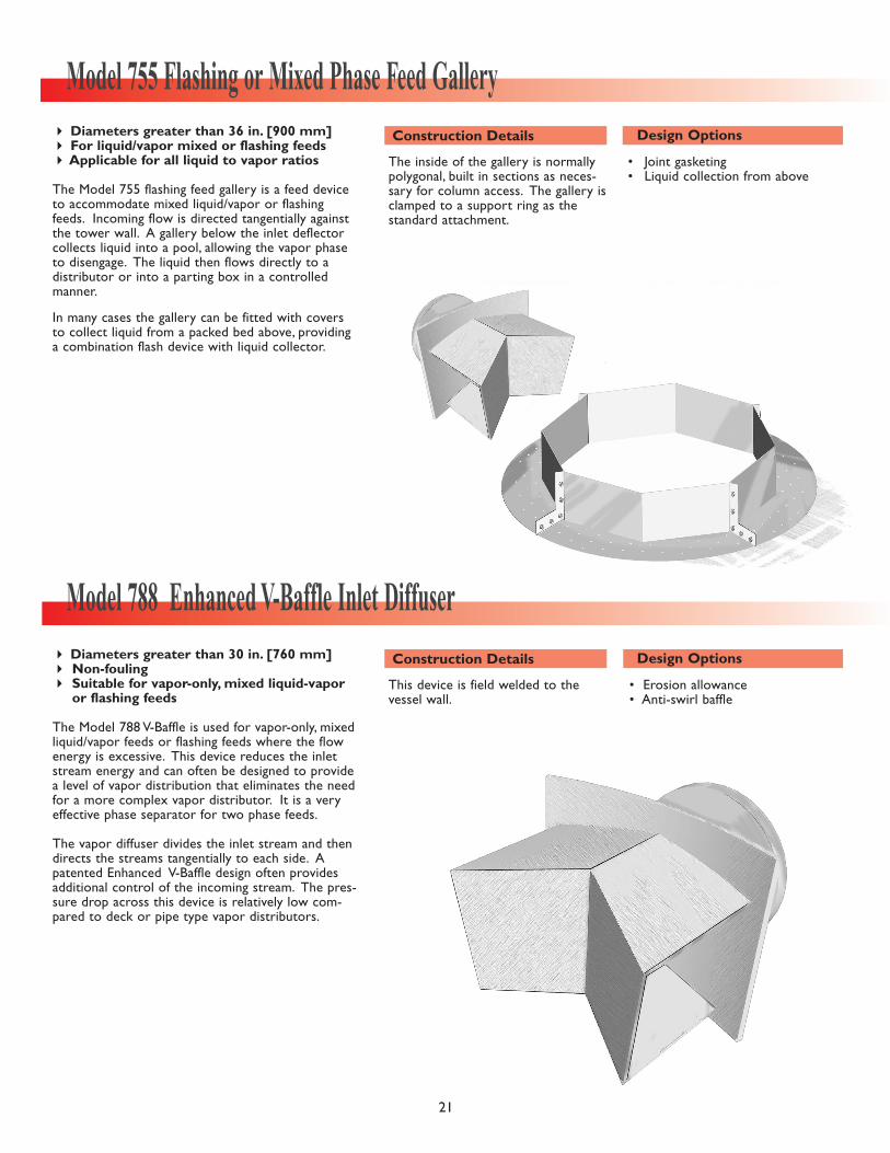
The inside of the gallery is normallypolygonal, built in sections as neces-sary for column access. The gallery isclamped to a support ring as thestandard attachment.
• Joint gasketing• Liquid collection from above
� Diameters greater than 36 in. [900 mm] � For liquid/vapor mixed or flashing feeds� Applicable for all liquid to vapor ratios
The Model 755 flashing feed gallery is a feed deviceto accommodate mixed liquid/vapor or flashingfeeds. Incoming flow is directed tangentially againstthe tower wall. A gallery below the inlet deflectorcollects liquid into a pool, allowing the vapor phaseto disengage. The liquid then flows directly to a distributor or into a parting box in a controlledmanner.
In many cases the gallery can be fitted with coversto collect liquid from a packed bed above, providinga combination flash device with liquid collector.
Model 755 Flashing or Mixed Phase Feed GalleryConstruction Details Design Options
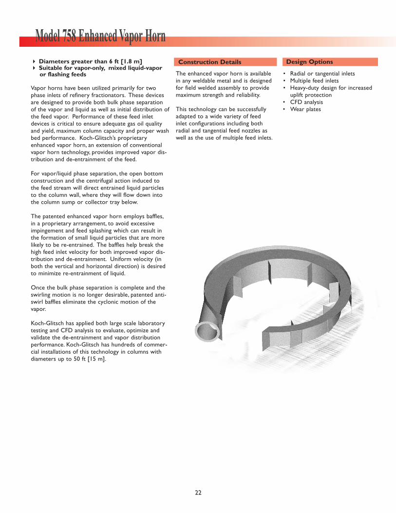
This device is field welded to the vessel wall.
• Erosion allowance• Anti-swirl baffle
� Diameters greater than 30 in. [760 mm] � Non-fouling� Suitable for vapor-only, mixed liquid-vapor
or flashing feeds
The Model 788 V-Baffle is used for vapor-only, mixedliquid/vapor feeds or flashing feeds where the flowenergy is excessive. This device reduces the inletstream energy and can often be designed to providea level of vapor distribution that eliminates the needfor a more complex vapor distributor. It is a veryeffective phase separator for two phase feeds.
The vapor diffuser divides the inlet stream and thendirects the streams tangentially to each side. Apatented Enhanced V-Baffle design often providesadditional control of the incoming stream. The pres-sure drop across this device is relatively low com-pared to deck or pipe type vapor distributors.
Model 788 Enhanced V-Baffle Inlet DiffuserConstruction Details Design Options
21
straub2r
KG_with_R
Model 758 Enhanced Vapor Horn
22
The enhanced vapor horn is availablein any weldable metal and is designedfor field welded assembly to providemaximum strength and reliability.
This technology can be successfullyadapted to a wide variety of feedinlet configurations including bothradial and tangential feed nozzles aswell as the use of multiple feed inlets.
• Radial or tangential inlets• Multiple feed inlets• Heavy-duty design for increased
uplift protection• CFD analysis• Wear plates
� Diameters greater than 6 ft [1.8 m]� Suitable for vapor-only, mixed liquid-vapor
or flashing feeds
Vapor horns have been utilized primarily for twophase inlets of refinery fractionators. These devicesare designed to provide both bulk phase separationof the vapor and liquid as well as initial distribution ofthe feed vapor. Performance of these feed inletdevices is critical to ensure adequate gas oil qualityand yield, maximum column capacity and proper washbed performance. Koch-Glitsch’s proprietaryenhanced vapor horn, an extension of conventionalvapor horn technology, provides improved vapor dis-tribution and de-entrainment of the feed.
For vapor/liquid phase separation, the open bottomconstruction and the centrifugal action induced tothe feed stream will direct entrained liquid particlesto the column wall, where they will flow down intothe column sump or collector tray below.
The patented enhanced vapor horn employs baffles,in a proprietary arrangement, to avoid excessiveimpingement and feed splashing which can result inthe formation of small liquid particles that are morelikely to be re-entrained. The baffles help break thehigh feed inlet velocity for both improved vapor dis-tribution and de-entrainment. Uniform velocity (inboth the vertical and horizontal direction) is desiredto minimize re-entrainment of liquid.
Once the bulk phase separation is complete and theswirling motion is no longer desirable, patented anti-swirl baffles eliminate the cyclonic motion of thevapor.
Koch-Glitsch has applied both large scale laboratorytesting and CFD analysis to evaluate, optimize andvalidate the de-entrainment and vapor distributionperformance. Koch-Glitsch has hundreds of commer-cial installations of this technology in columns withdiameters up to 50 ft [15 m].
Construction Details Design Options
straub2r
KG_with_R
The main header attaches to an inletflange (supplied by others) and is fur-ther supported supplied by a wallclip. The laterals are supported bywall clips, as needed.Access diametermust be sufficient to accommodatethe header assembly. For large diame-ter headers, where manway access islimiting, field welding may berequired.
Laterals are flanged as the standard,but may have threaded connectionsfor pipes 4 in. [100 mm] and less.
• All flanged construction • Bayonet-type for small columns
� Diameters greater than 18 in. [450 mm]� Vapor-only inlet streams
The Model 746 lateral arm vapor distributor is usedwhen a vapor feed requires uniform distributionacross the tower area. Typical applications includevapor feed at the bottom of the tower or betweenbeds.
When used at the bottom of a tower it can savetower elevation compared to a deck type (model716) vapor distributor. When used between beds, itwill ensure that the vapor feed is well distributedand well mixed with the vapor from the bed below.
To achieve good distribution the required pressuredrop across the vapor distributor is determined bythe flow rate and size of the inlet. Turndown is gen-erally 4 : 1, but can be higher or lower dependingupon the allowable pressure drop for the process.
Model 746 Lateral Arm Vapor DistributorConstruction Details Design Options
The Model 716 vapor distributor isclamped to a support ring and typi-cally requires bolting bars and seg-mental supports for its downcomerand seal pan. Midspan beams may beused for larger diameter towers.
Standard construction will withstand50 lbs/ft2 [0.024 bar] upward force.However, special designs are availablewhich can withstand greater upliftrequirements.
• Liquid draw sump• Pipe downcomers, if applicable• Uplift specifications
� Diameters greater than 30 in. [760 mm]
The Model 716 vapor distributor is a deck type usedto correct poor vapor distribution below a packedbed. This device can be used between packed bedswhere a vapor feed is introduced or above reboilerreturn streams.
The vapor is metered through vapor risers as liquidis collected from a packed bed above. The liquidleaves the vapor distributor through a downcomer.To perform the task of vapor distribution, the Model716 will consume some pressure drop.
The turndown ratio is generally about 4 : 1, providedpressure drop is not excessive for the process.
Model 716 Deck Type Vapor DistributorConstruction Details Design Options
23
straub2r
KG_with_R
This device is attached to an internaltower inlet flange (supplied by others) and is further supported bya vessel wall clip as the standard construction.
Optionally, the inside pipe can bedesigned to bayonet into the vaporinlet nozzle, in lieu of an internalflange.
One-piece construction is standardprovided column access diameter issufficient. Otherwise, multi-piececonstruction is provided. In somecases, field welding of multi-piececonstruction may be required.
• Bayonet inlet construction
� Diameters greater than 48 in. [1200 mm]� Vapor-only inlet streams
The Model 748 vapor diffuser is used for vapor-onlyfeeds where the flow energy is excessive. Thisdevice is not a vapor distributor. It reduces thevapor energy such that a more complex vapor distributor may not be necessary.
The vapor diffuser uniformly meters the vaporstream out the upper area of the pipe and theshroud and then directs the flow downward to eachside. The pressure drop across this device is relatively low compared to the Model 746 vapor distributor.
Turndown is generally 4 : 1.
Model 748 Vapor DiffuserConstruction Details Design Options
Multi-piece construction is supplied for installation througha vessel manway. Flanged andbolted construction is supplied as the standard. Field welded con-struction is an available option.
The inlet attachment requires weld-ing to the vessel wall. Additionalsupport clips welded to the vesselmay be required. As an option,attachment can be made to anexisting internal nozzle flange.
• Field welded construction• Attachment to existing flange• CFD analysis
� Diameters greater than 72 in. [1800 mm]� Preferred for vapor-only feed
The Model 768 EVENFLOW™ vane type vapor dis-tributor is used for high energy vapor inlet streamsentering through a radial inlet. Although the devicehas been utilized in applications with high velocitymixed phase feeds, the performance of the device isbest when limited to vapor-only feeds.
Baffles used in conjunction with a tapered configura-tion provide vapor distribution with minimal pres-sure drop. The curved baffle plates partition theinlet vapor stream into multiple small segments,reducing the velocity and directing the segmentedstreams horizontally across the column area.
Performance of the EVENFLOW vapor distributorhas been validated using CFD analysis as well asnumerous successful commercial installations.


![[Glitsch] - Ballast Tray - Bullettin 4900](https://static.documents.pub/doc/80x56/55cf940e550346f57b9f55ec/glitsch-ballast-tray-bullettin-4900-56800c9a48f39.jpg)


