+ All Categories
Home > Documents > Feeney Architectural Products Design-Rail™ Glass...

Feeney Architectural Products Design-Rail™ Glass...

Date post: 23-Apr-2018
Category:
Upload: lenhan
View: 219 times
Download: 2 times
Share this document with a friend
51
Feeney Architectural Products Design-Rail™ Glass Infill 09/09/2010 Page 1 of 51 EDWARD C. ROBISON, PE 10012 Creviston Dr NW Gig Harbor, WA 98329 253-858-0855/Fax 253-858-0856 [email protected] 09 SEP 2010 Feeney Inc. 2603 Union Sreet Oakland, CA94607 SUBJ: FEENEY ARCHITECTURAL DESIGN-RAIL™ ALUMINUM RAILING GLASS INFILL SYSTEMS SERIES 100, 150, 200, 300, 350 AND 400 SERIES SYSTEMS The Design-Rail System (DRS) utilizes aluminum extrusions and tempered glass infill to construct building guards and rails for decks, balconies, stairs, fences and similar locations. The system is intended for interior and exterior weather exposed applications and is suitable for use in all natural environments. The DRS may be used for residential, commercial and industrial applications. The DRS is an engineered system designed for the following criteria: The design loading conditions are: On Top Rail: Concentrated load = 200 lbs any direction, any location Uniform load = 50 plf, any direction perpendicular to top rail On In-fill Panels: Concentrated load = 50# on one sf. Distributed load = 25 psf on area of in-fill, including spaces Wind load = 28.5 psf typical installation (higher wind loads may be allowed based on post spacing and anchorage method) Refer to IBC Section 1607.7.1 for loading. The DRS system will meet or exceed all requirements of the 1997 Uniform Building Code, 2000, 2003, 2006 and 2009 International Building Codes, Florida Building Code (non-hurricane zones), 2007 California Building Code and 2005 Aluminum Design Manual. Wood components and anchorage to wood are designed in accordance with the National Design Specification for Wood Construction. Edward Robison, P.E.
Transcript

Feeney Architectural Products Design-Rail™ Glass Infill 09/09/2010 Page 1 of 51

EDWARD C. ROBISON, PE10012 Creviston Dr NWGig Harbor, WA 98329

253-858-0855/Fax 253-858-0856 [email protected]

09 SEP 2010Feeney Inc.2603 Union SreetOakland, CA94607

SUBJ: FEENEY ARCHITECTURAL DESIGN-RAIL™ALUMINUM RAILINGGLASS INFILL SYSTEMSSERIES 100, 150, 200, 300, 350 AND 400 SERIES SYSTEMS

The Design-Rail System (DRS) utilizes aluminum extrusions and tempered glass infill toconstruct building guards and rails for decks, balconies, stairs, fences and similarlocations. The system is intended for interior and exterior weather exposed applicationsand is suitable for use in all natural environments. The DRS may be used for residential,commercial and industrial applications. The DRS is an engineered system designed forthe following criteria:

The design loading conditions are:On Top Rail:

Concentrated load = 200 lbs any direction, any locationUniform load = 50 plf, any direction perpendicular to top rail

On In-fill Panels:Concentrated load = 50# on one sf.Distributed load = 25 psf on area of in-fill, including spacesWind load = 28.5 psf typical installation (higher wind loads may be allowed

based on post spacing and anchorage method)Refer to IBC Section 1607.7.1 for loading.

The DRS system will meet or exceed all requirements of the 1997 Uniform BuildingCode, 2000, 2003, 2006 and 2009 International Building Codes, Florida Building Code(non-hurricane zones), 2007 California Building Code and 2005 Aluminum DesignManual. Wood components and anchorage to wood are designed in accordance with theNational Design Specification for Wood Construction.

Edward Robison, P.E.

Feeney Architectural Products Design-Rail™ Glass Infill 09/09/2010 Page 2 of 51

EDWARD C. ROBISON, PE10012 Creviston Dr NWGig Harbor, WA 98329

253-858-0855/Fax 253-858-0856 [email protected]

Contents: PageTypical Installations 3Load Cases 4Wind Loading on Balcony Rails 5Glass Strength - Infill 6 – 9Standard Post 1045˚ Corner Post 11Connection to Base Plate 12Base Plate Design (5”x5”) 12 – 13Base Plate Anchorage 13Offset Base Plate 13Narrow Base Plate (3”x5”) 14Base Plate Mounted to Wood 15Base Plate Mounted to Concrete 16Core Mounted Posts 17Fascia Bracket 18 – 22Fascia Mounted Post 23 – 26Stanchion Mount 27Stanchion Welded to Base Plate 28Pool Fence/Wind Fence 29Series 100 Top Rail Type 1 30

Contents: PageSeries 150 Top Rail 31Universal Bottom Rail 32Series 100/150 Top Rail to Post 33Intermediate Post Fitting Ser 100/15 34Series 200 Top Rail 35Series 300 Top Rail 36Series 350 Top Rail 37Series 400 Top Rail 38Top Rail Vertical Load Sharing 39Glass Infill Insert 40Top Rail to Post Connection 41Top Rail Splices 42Intermediate Rail 43Wind Screen Mid Rail 44Glass Infill Bottom Rail 45Post Rail Connection Block 46Wall Mount End Caps 47 – 48Grab Rail Bracket 49 – 50Lag Screw Withdrawal From Wood 51

edwardrobison
Text Box
Signed 09/09/2010

Feeney Architectural Products Design-Rail™ Glass Infill 09/09/2010 Page 3 of 51

EDWARD C. ROBISON, PE10012 Creviston Dr NWGig Harbor, WA 98329

253-858-0855/Fax 253-858-0856 [email protected]

TYPICAL INSTALLATIONS:

Surface mounted with base plates:3/8” mounting hardware depends on substrate refer to calculations for hardwarespecifics.

Residential Applications:Rail Height 36” above finish floor.Standard Post spacing 6’ on center maximum.All top rails

Commercial and Industrial Applications:Rail Height 42” above finish floor.Standard Post spacing 5’ on center maximum.All top rails

Pool Fence/Wind Fence4’ post spacing, 4’ post height – 25 psf wind load4’ post spacing, 4’ 5.75” post height – 20 psf wind load4’ post spacing, 5’ post height – 16 psf wind load

Core pocket /embedded posts or stainless steel stanchion mounted:Residential Applications:Rail Height 36” above finish floor.Standard Post spacing 6’ on center maximum, series 100, 150 and 400.

8’ on center Series 200, 300, and 350.

Commercial and Industrial Applications:Rail Height 42” above finish floor.Standard Post spacing 5’ on center maximum, series 100, 150 and 400

6’ on center Series 200, 300, and 350.

Pool Fence/Wind Fence4’ post spacing, 4’ 9” post height – 25 psf wind load (3/8” glass)4’ post spacing, 5’ post height – 23 psf wind load

Feeney Architectural Products Design-Rail™ Glass Infill 09/09/2010 Page 4 of 51

EDWARD C. ROBISON, PE10012 Creviston Dr NWGig Harbor, WA 98329

253-858-0855/Fax 253-858-0856 [email protected]

LOAD CASES:Glass rail Dead load = 5 plf for 42” rail height or less.

Loading:Horizontal load to top rail from in-fill:25 psf*H/2Post momentsMi = 25 psf*H*S*H/2 =

= 12.5*S*H2

For top rail loads:Mc = 200#*HMu = 50plf*S*H

For wind load surface area:

Mw = w psf*H*S*H/2 = = 0.5w*S*H2

Solving for w :w = 2M/( S*H2)

Wind load equivalent for 42” rail height, 5’post spacing 50 plf top rail load:Mu = 50plf*5’*3.5’ = 875#’ = 10,500#”

w = 2*875/( 5*3.52) = 28.57 psf

Allowable wind load adjustment for other post spacing:

w = 28.57*(5/S)

Feeney Architectural Products Design-Rail™ Glass Infill 09/09/2010 Page 5 of 51

EDWARD C. ROBISON, PE10012 Creviston Dr NWGig Harbor, WA 98329

253-858-0855/Fax 253-858-0856 [email protected]

WIND LOADING ON A BALCONY RAILS

Calculated in accordance with SEI/ASCE 7-05 Section 6.5.13 Design Wind Loads onOpen Buildings and Other Structures. This section is applicable for free standingguardrails, wind walls and balcony railings because they are not part of the buildingstructural frame, are open on all sides and do not receive loading from anything otherthan the railing surface. Section 6.5.12.4 Components and Cladding is not applicablebecause the rails are not part of the building envelope but are outside of the buildingenvelope. Section 6.5.12.4.4 Parapets may be applied to any of the exposed rails but theresults will be essentially the same as Section 6.5.13 because GCpi = 0 for the railingsbecause all sides are open with no internal pressure so the equation simplifies to:

p = qp(GCp) = qzGCf

For guardrails the coefficients have the following values:G = 0.85 from section 6.5.8.2 for a relatively stiff structure.Cf = 1.2 From Figure 6-20.Qz = KzKztKdV2I Where:

I = 1.0Kz from Table 6-3 at the height z of the railing centroid and exposure.Kd = 0.85 from Table 6-4.Kzt From Figure 6-4 for the site topography, typically 1.0.V = Wind speed (mph) 3 second gust, Figure 6-1 or per local authority.

28.5 psf wind load is equivalent to the following wind speeds and exposures (Kzt = 1.0):

85 mph Exp B, 600’ above grade85 mph Exp C, 350’ above grade85 mph Exp D, 225’ above grade

95 mph Exp B, 275’ above grade95 mph Exp C, 120’ above grade95 mph Exp D, 60’ above grade

105 mph Exp B, 130’ above grade105 mph Exp C, 45’ above grade105 mph Exp D, 20’ above grade

115 mph Exp B, 70’ above grade115 mph Exp C, 20’ above grade

Feeney Architectural Products Design-Rail™ Glass Infill 09/09/2010 Page 6 of 51

EDWARD C. ROBISON, PE10012 Creviston Dr NWGig Harbor, WA 98329

253-858-0855/Fax 253-858-0856 [email protected]

GLASS STRENGTH - INFILL PANELS

All glass is fully tempered glass conforming to the specifications of ANSI Z97.1,ASTM C 1048-97b and CPSC 16 CFR 1201. The typical Modulus of Rupture for theglass, Fr is ≥ 24 ksi. In accordance with UBC 2406.6 or IBC 2407.1.1 glass used asstructural balustrade panels shall be designed for a safety factor of 4.0. This is applicableonly to structural panels (glass provides support to railing). Other locations the glassstress may be increased by 33% (SF = 3.0) for glass when there is no fall hazard. Glassnot used in guardrails may be designed for a safety factor of 2.5 in accordance withASTM E1300-00.

Values for the modulus of rupture, Fr, modulus of Elasticity, E and shear modulus, G forglass are typically taken as:

FR = 24,000 psi based on numerous published data from various glassmanufacturers. This value is recognized in ASTM E 1300-00, ANSI Z97.1, ASTM C1048-97b and CPSC 16 CFR 1201 (derivation of the value is required using the providedformulae and properties). This value is referenced in numerous publications, designmanuals and manufacturers’ literature.

E = 10,400 ksi is used as the standard value for common glass. While the valueof E for glass varies with the stress and load duration this value is typically used as anaverage value for the stress range of interest. It can be found in ASTM E 1300 andnumerous other sources.

G = 3,800 ksi: This is available from various published sources but is rarely usedwhen checking the deflection in glass. The shear component of the deflection tends to bevery small, about 1% of the bending component and is therefore ignored.

ν = 0.22 (Typical value of Poisson’s ratio for common glasses).µ = 5x10⁻⁶ in/(in˚F) (Typical thermal coefficient for common glass).

The safety factor of 4 is dictated by the building code (1997 UBC 2406.6, 2006 IBC2407.1.1). It is applied to the modulus of rupture since glass as an inelastic material doesnot have a yield point. The safety factor of 4 is applicable to glass stresses. Non-glasselements are designed in accordance with the applicable code sections for the material.

There is no deflection limits for the glass in guards other than practical limits for theopening sizes, retention in the frames and occupant comfort. Refer to ASTM E 1300-00for a standard method of calculating deflections but the deflection limits are concernedwith glazing in windows and similar parts of the building envelope rather than a freestanding guard. IBC 2403.3 applies a limit of L/175 or 3/4” for the supporting frame.From IBC Table 1604.3 footnote h similar types of construction have a limit of L/60.

The shear strength of glass tracks closely to the modulus of rupture because failure undershear load will be a tensile failure with strength limited by the modulus of rupture. Thusshear loads are transformed using Mohr’s circle to determine the critical tension stress to

Feeney Architectural Products Design-Rail™ Glass Infill 09/09/2010 Page 7 of 51

EDWARD C. ROBISON, PE10012 Creviston Dr NWGig Harbor, WA 98329

253-858-0855/Fax 253-858-0856 [email protected]

evaluate the failure load. The safety factor of 4 is applicable to this case same as thebending case. Thus the shear stress is limited based on principal stresses of 0 and 6,000psi to 6,000/2 = 3,000 psi. Bearing stress can be derived in a similar fashion with theprincipal stresses being –6,000 psi and 6,000 psi so the bearing stress = 6,000 psi.

Bending strength of glass for the given thickness:I = 12”*(t)3 /12= (t)3 in3/ftS = 12”*(t)2 /6= 2*(t)2 in3/ft

For lites simply supported on two opposite sides the moment and deflection arecalculated from basic beam theory

Mw = W*L2/8 for uniform load W and span L orMp = P*L/4 for concentrated load P and span L, highest moment P @ center

Maximum wind loads:W = Ma*8/L2 for uniform load W and span L (rail to rail distance)

Deflection can be calculated using basic beam theory:Δ = 5wL4/(384EI) for uniform load

Simplifying:Δ = [wL4/t3]/(9.58 x 109)for w in psf and L in inches

For concentrated load:Δ = PL3/(48EI)

Simplifying:Δ = PL3/(4.992*108t3)

Maximum allowable deflection: Use L/60 deflection limit for infill. This will preventglass from deflecting enough to disengage from the frame.

For uniform load (wind load)Solving for w

w = [t3*1.595*108]/L3

Solving for LL = [(t3*1.595*108)/w]1/3

Solving for tt = [L3w/(1.595*108)]1/3

For Concentrated loadSolving for P

P = (8.32*106t3)/L2

Solving for LL = [8.32*106*t3/P]1/2

Solving for tt = [PL2/(8.32*106)]1/3

Feeney Architectural Products Design-Rail™ Glass Infill 09/09/2010 Page 8 of 51

EDWARD C. ROBISON, PE10012 Creviston Dr NWGig Harbor, WA 98329

253-858-0855/Fax 253-858-0856 [email protected]

From IBC 2407 the minimum nominal glass thickness for infill panels in guards is 1/4”

1/4” FULLY TEMPERED GLASSWeight = 2.89 psitave = 0.223”

For 1/4” glass S = 2*(0.223)2 = 0.0995 in3/ftMallowable = 6,000psi*0.0995 in3/ft = 597#”/ft

For FS = 3.0 (no fall hazard, glass fence or wind screen)Mall = 597”#*4/3 = 796”#

Moment for 36” wide lite (infill for 42” rail height) 25 psf or 50 lb loadMw = 25psf*3’2*12”/’/8= 337.5”#Mp = 50*36”/4 = 450”#

Moment for 42” wide lite (infill for 48” rail height) 25 psf or 50 lb loadMw = 25psf*3.5’2*12”/’/8= 459.4”#Mp = 50*42”/4 = 525”#

for 36” wide lite (infill for 42” rail height)W = 597”#*8/(3’*36”)= 44 psf

for 42” wide lite (infill for 48” rail height)W = 597”#*8/(3.5’*42”)= 32.5 psf

Deflection:36” wide lite (infill for 42” rail height) 25 psf or 50 lb load

L/60 = 36/60 = 0.60Δ = [25*364/0.253]/(9.58 x 109) = 0.28”

or Δ = 50*363/(4.992*108*0.253) = 0.30”

Maximum width for 50# load at center of 2’ long light:H = 2*597”#*4/50 = 95.5” (will not limit height for lights over 1’3” wide)

For Pool Fence or Wind Fence (SF = 4.0)Allowable wind load:For 48” wide light:

W = 796”#*8/(4’*48”)= 33.17 psfFor 60” wide light:

W = 796”#*8/(5’*60”)= 21.2 psfMaximum width for 25 psf:

H = √(796”#/12*8/25) = 4.607’

Feeney Architectural Products Design-Rail™ Glass Infill 09/09/2010 Page 9 of 51

EDWARD C. ROBISON, PE10012 Creviston Dr NWGig Harbor, WA 98329

253-858-0855/Fax 253-858-0856 [email protected]

3/8” FULLY TEMPERED GLASS

Weight = 4.75 psitave = 0.366”

For 3/8” glass S = 2*(0.366)2 = 0.268 in3/ftMallowable = 6,000psi*0.268 in3/ft = 1,607#”/ft

For FS = 3.0 (no fall hazard, glass fence or wind screen)Mall = 1,607”#*4/3 = 2,143#”

Moment for 36” wide lite (infill for 42” rail height) 25 psf or 50 lb loadMw = 25psf*3’2*12”/’/8= 337.5”#Mp = 50*36”/4 = 450”#

Moment for 42” wide lite (infill for 48” rail height) 25 psf or 50 lb loadMw = 25psf*3.5’2*12”/’/8= 459.4”#Mp = 50*42”/4 = 525”#

for 36” wide lite (infill for 42” rail height)W = 1,607”#*8/(3’*36”)= 119 psf

for 42” wide lite (infill for 48” rail height)W = 1,607”#*8/(3.5’*42”)= 87.5 psf

Deflection:36” wide lite (infill for 42” rail height) 25 psf or 50 lb load

L/60 = 36/60 = 0.60Δ = [25*364/0.3663]/(9.58 x 109) = 0.089”

or Δ = 50*363/(4.992*108*0.3663) = 0.095”

Check maximum wind load based on deflection:

36” width w = [0.3663*1.595*108]/363 = 167 psf (does not control)42” width w = [0.3663*1.595*108]/423 = 105 psf (does not control)

For Pool Fence or Wind Fence (SF = 4.0)Allowable wind load:For 48” wide light:

W = 1,607”#*8/(4’*48”)= 67 psfFor 60” wide light:

W = 1,607”#*8/(5’*60”)= 42.9 psfMaximum width for 25 psf:

H = √(1,607”#/12*8/25) = 6.546’

Feeney Architectural Products Design-Rail™ Glass Infill 09/09/2010 Page 10 of 51

EDWARD C. ROBISON, PE10012 Creviston Dr NWGig Harbor, WA 98329

253-858-0855/Fax 253-858-0856 [email protected]

STANDARD POST – 2-3/8” SquarePost Strength

6005-T5 or 6061-T6

Post-Area 0.995”Ixx = Iyy = 0.863 in4

S = 0.726 in3

r = 0.923 inJ = 0.98 in

k ≤ 1 for all applications

Allowable bending stress ADM Table 2-21

S1 = LB SC = LB • 0.726 = 1.58 LB

0.5 Iy J 0.5 0.863 • 0.98

for LB ≤ 146 = 92” → FCB = 21 ksi 158

for LB > 92” FCB= 2.39–0.24(1.58 LB)1/2

POST EXTRUSION ACTUAL SIZE

Mall = 0.726 • 19ksi = 13,794 #” = 1,149#ft

2.375”

t = 0.1

Feeney Architectural Products Design-Rail™ Glass Infill 09/09/2010 Page 11 of 51

EDWARD C. ROBISON, PE10012 Creviston Dr NWGig Harbor, WA 98329

253-858-0855/Fax 253-858-0856 [email protected]

45˚ Corner Post

6005-T5 or 6061T6

Post Section PropertiesArea 1.355”Ixx = 1.120 in4

Iyy = 1.742 in4

Sxx = 0.812 in3

Syy = 0.900 in3

rxx = 0.975 inryy = 1.175 inJ = 1.146 ink = 1 for all applications

Allowable bending stress ADM Table 2-21

S1 = LB SC = LB • 0.900 = 0.5 Iy J 0.5 1.120 • 1.146

=1.58 LB

for LB ≤ 146 = 92” → FCB = 21 ksi 1.58

for LB > 92” FCB= 2.39–0.24(1.58 LB)1/2

Mall = 0.812 • 19ksi = 15,428 #” = 1,286#ft

Connection to base platePost uses standard base plate

2.12500

2.3750 0

Feeney Architectural Products Design-Rail™ Glass Infill 09/09/2010 Page 12 of 51

EDWARD C. ROBISON, PE10012 Creviston Dr NWGig Harbor, WA 98329

253-858-0855/Fax 253-858-0856 [email protected]

CONNECTION TO BASE PLATE

Failure modes → screw tension→ screw shear→ screw withdrawal

For screw withdrawal see ADM 5.4

W = 2.3 • e • d • π • Fsy

e = full thread engagement = 1”d = max root diameter = 0.248” minor = 0.185”Base plate to post screws are AISI 4037 steelalloy fabricated in accordance with SAE J429Grade 8 and coated with Magni 550 corrosionprotection.

Fsy = 20 ksi

W = 2/3 • 1” • 0.248” • π • 20ksi

W = 10.39k

W’ = 10.39 = 3.46k

3.0 Safety factor

Screw tension → Ty = 0.0483 in2 • 110 ksi = 5314 # Vu = 0.0483* 45ksi =2,174#

FtU = 0.0376 • 150 ksi = 5640#

Safety factors for screws calculated from SEI/ASCE 8-02 Section 5 LRFD factorsFor yielding SF = 1.6/0.75 = 2.13 → 5,314#/2.13 = 2,495#

For fracture SF = 1.6/0.65 = 2.46 → 5640/2.46 = 2,293#

Shear strengthFor fracture SF = 1.6/(0.9*0.75) = 2.37 → 5,640/2.37 =2,380#

BASE PLATE DESIGNBase plate bending stress

Ft = 24 ksi → Smin = 5” • 3/82 = 0.117 in3

6

Major root area

average root area

4.375"

2.28"

.8125"1.3125"

5"

.375"

Cp Ts

Cb

Tb

Feeney Architectural Products Design-Rail™ Glass Infill 09/09/2010 Page 13 of 51

EDWARD C. ROBISON, PE10012 Creviston Dr NWGig Harbor, WA 98329

253-858-0855/Fax 253-858-0856 [email protected]

Base plate allowable moment Mall = 24 ksi • 0.117 in3 = 2,812 “#

→ Base plate bending stressTB = C

M = 0.8125” • TB • 2

Tall = 2,812 = 1,730#

2 • 0.8125

Maximum post moment for base plate strengthMall = 2 • 1730 • 4.375” = 15,142#“

Limiting factor = screws to postMult = 2 • 5,314# • 2.28” = 24,232#”Mall = 2 • 2,293# • 2.28” = 10,456”#

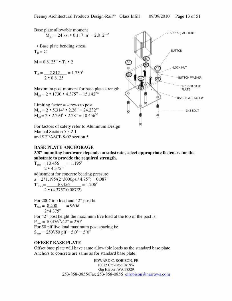
For factors of safety refer to Aluminum DesignManual Section 5.3.2.1and SEI/ASCE 8-02 section 5

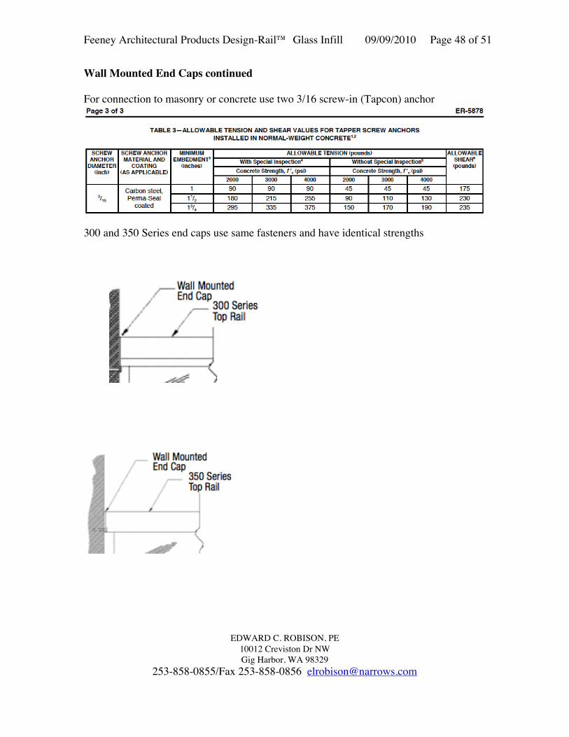
BASE PLATE ANCHORAGE3/8” mounting hardware depends on substrate, select appropriate fasteners for thesubstrate to provide the required strength.TDes = 10,456 = 1,195#

2 • 4.375”adjustment for concrete bearing pressure:a = 2*1,195/(2*3000psi*4.75”) = 0.087”T’Des = 10,456 = 1,206#

2 • (4.375”-0.087/2)

For 200# top load and 42” post htT200 = 8,400 = 960# 2*4.375”For 42” post height the maximum live load at the top of the post is:Pmax = 10,456”#/42” = 250#

For 50 plf live load maximum post spacing is:Smax = 250#/50 plf = 5.0’ = 5’0”

OFFSET BASE PLATEOffset base plate will have same allowable loads as the standard base plate.Anchors to concrete are same as for standard base plate.

2 3/8" SQ. AL. TUBE

BUTTON

LOCK NUT

BUTTON WASHER

5x5x3/8 BASE PLATE

BASE PLATE SCREW

3/8 BOLT

Feeney Architectural Products Design-Rail™ Glass Infill 09/09/2010 Page 14 of 51

EDWARD C. ROBISON, PE10012 Creviston Dr NWGig Harbor, WA 98329

253-858-0855/Fax 253-858-0856 [email protected]

NARROW BASE PLATEThe narrow base plate attaches to thepost with the same screws as thestandard base plate.

For long dimension perpendicular tothe guard the bolt loads may beassumed as the same as for thestandard 5x5 base plate.

For base plate oriented with the longdimension parallel to the guard thedesign anchor load is:T = 10,500/(2*2.8”) = 1,875#

When attached to steel with 3/8” boltsthe narrow base plate may be orientedin either direction.

When attached to wood with the base plate oriented with the long dimensionperpendicular to the guard there is no reduction in load with the lag screw sizes ascalculated on page 10.

When attached to wood using lag screws with the base plate oriented with the longdimension parallel to the guard the allowable load per post is multiplied by 0.7.For example if the base plate is attached with 6” lag screws on a weather exposed deckthe maximum post height is reduced to:

H = 0.7*42” = 29.4”

When attached to wood using 3/8” hex bolts with the base plate oriented with the longdimension parallel to the guard the allowable load per post is the same as for the standardbase plate provided that a base plate is used under the nuts with washers.

When installed to concrete the anchors shall be custom designed for the imposed loadsbased on the actual conditions of the proposed installation. The standard concrete anchordesign shown herein for the 5x5 base plate may not be used because the anchor spacing isinadequate.

Feeney Architectural Products Design-Rail™ Glass Infill 09/09/2010 Page 15 of 51

EDWARD C. ROBISON, PE10012 Creviston Dr NWGig Harbor, WA 98329

253-858-0855/Fax 253-858-0856 [email protected]

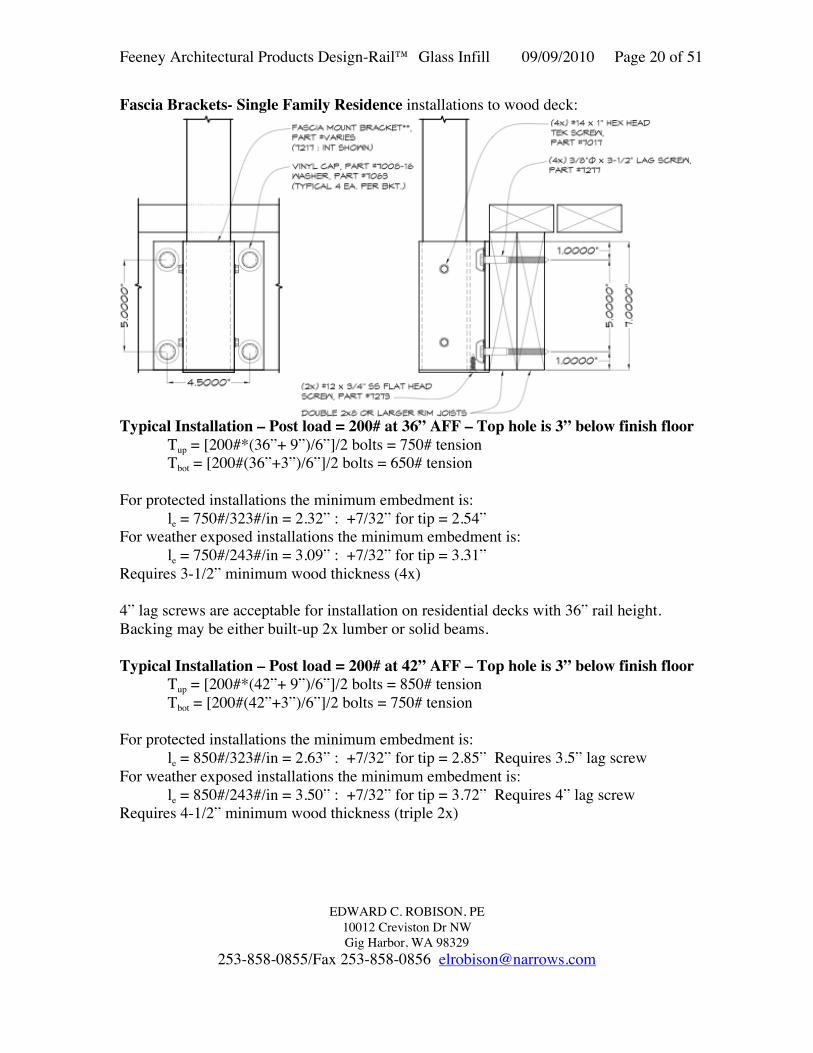
BASE PLATE MOUNTED TO WOOD – SINGLE FAMILY RESIDENCE36” GUARDSFor 200# top load and 36” post height: M = 200#*36” = 7,200”#T200 = 7,200 = 823# 2*4.375”Adjustment for wood bearing:a = 2*823/(1.33*625psi*5”)= 0.4”T = 7,200/[2*(4-0.4/2)]= 947#

Required embed depth:For protected installations theminimum embedment is:le = 947#/323#/in = 2.93” :+7/32” for tip = 3.15”For weather exposed installationsthe minimum embedment is:le = 947#/243#/in = 3.90” :+7/32” for tip = 4.12”

FOR 36” HIGH WEATHER EXPOSED INSTALLATIONS USE 5” LAGSCREWS AND INCREASE BLOCKING TO 4.5” MINIMUM THICKNESS.

42” HIGH GUARDSFor 200# top load and 42” post height: M = 200#*42” = 8,400”#T200 = 8,400 = 960# 2*4.375”Adjustment for wood bearing:a = 2*960/(1.33*625psi*5”)= 0.462”T = 8,400/[2*(4-0.462/2)]= 1,114#Required embed depth:For protected installations the minimum embedment is:le = 1,114#/323#/in = 3.45” : +7/32” for tip = 3.67” 4.5” minimum lag length.

For weather exposed installations the minimum embedment is:le = 1,114#/243#/in = 4.58” : +7/32” for tip = 4.80”

FOR 42” HIGH WEATHER EXPOSED INSTALLATIONS USE 6” LAGSCREWS AND INCREASE BLOCKING TO 5.5” MINIMUM THICKNESS.

3/8” Stainless steel bolts with heavy washers bearing on the wood may be usedthrough the solid wood blocking with a minimum 3” nominal thickness.

Feeney Architectural Products Design-Rail™ Glass Infill 09/09/2010 Page 16 of 51

EDWARD C. ROBISON, PE10012 Creviston Dr NWGig Harbor, WA 98329

253-858-0855/Fax 253-858-0856 [email protected]

BASE PLATE MOUNTED TO CONCRETE - Expansion Bolt Alternative:Base plate mounted to concrete with ITW Red Head Trubolt wedge anchor 3/8”x3.75”concrete anchors with 3” effective embedment. Anchor strength based on ESR-2251Minimum conditions used for the calculations:f’c ≥ 3,000 psiedge distance =2.25” spacing = 3.75”h = 3.0”: embed depthFor concrete breakout strength:Ncb = [ANcg/ANco]ϕed,Nϕc,Nϕcp,NNb

ANcg= (1.5*3*2+3.75)*(1.5*3+2.25) = 86.06 in2 2 anchorsANco= 9*32 = 81 in2

Ca,min = 1.5” (ESR-2251 Table 3)Cac = 5.25” (ESR-2251 Table 3)ϕed,N = 1.0ϕc,N = (use 1.0 in calculations with k = 24)ϕcp,N= max (1.5/5.25 or 1.5*3”/5.25) = 0.857 (ca,min ≤cac)Nb = 24*1.0*√3000*3.01.5 = 6,830#Ncb = 86.06/81*1.0*1.0*0.857*6,830 = 6,219 ≤ 2*3,469based on concrete breakout strength.Determine allowable tension load on anchor pairTs = 0.65*6,219#/1.6 = 2,526#Check shear strength - Concrete breakout strength in shear:Vcb = Avc/Avco(ϕed,Vϕc,Vϕh,VVb

Avc = (1.5*3*2+3.75)*(2.25*1.5) = 43.03Avco= 4.5(ca1)2 = 4.5(3)2 = 40.5ϕed,V= 1.0 (affected by only one edge)ϕc,V= 1.4 uncracked concreteϕh,V= √(1.5ca1/ha) = √(1.5*3/3) =1.225Vb= [7(le/da)0.2√da]λ√f’c(ca1)1.5 = [7(3.0/0.375)0.2√0.375]1.0√2500(3.0)1.5 =1,688#Vcb = 43.03/40.5*1.0*1.4*1.225*1,688# = 3,076#Steel shear strength = 4,825#*2 = 9,650Allowable shear strengthØVN/1.6 = 0.70*3,076#/1.6 = 1,346#Shear load = 4.87*50/1,346 = 0.18 ≤ 0.2Therefore interaction of shear and tension will not reduce allowable tension load:Ma = 2,526#*4.375” = 11,053# > 10,653#

ALLOWABLE SUBSTITUTIONS: Use same size anchor and embedmentHilti Kwik Bolt TZ in accordance with ESR-1917Powers Power Stud+ SD2 in accordance with ESR-2502Powers Wedge-Bolt+ in accordance with ESR-2526

Feeney Architectural Products Design-Rail™ Glass Infill 09/09/2010 Page 17 of 51

EDWARD C. ROBISON, PE10012 Creviston Dr NWGig Harbor, WA 98329

253-858-0855/Fax 253-858-0856 [email protected]

CORE MOUNTED POSTS

Mounted in either 4”x4”x4” blockout, or 4” to 6” dia by 4” deep cored hole.Minimum hole diameter = 3 3/8”Assumed concrete strength 2,500 psifor existing concrete

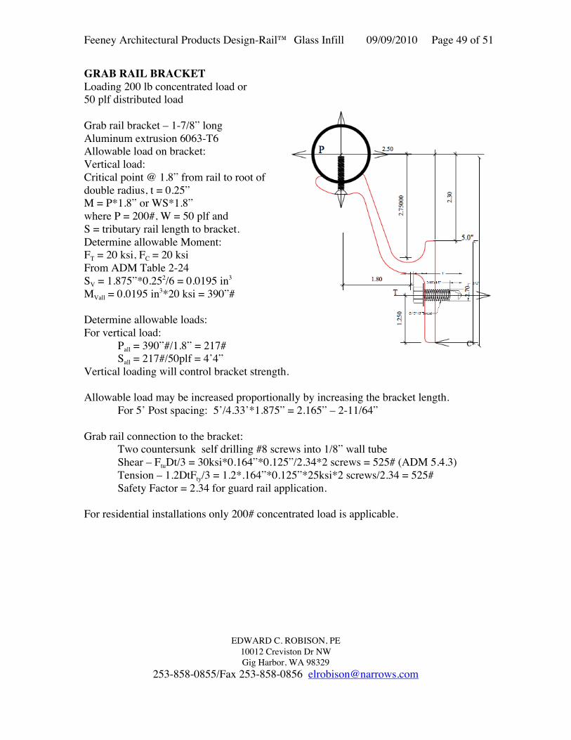
Max load – 6’•50 plf = 300#

M = 300#•42” = 12,600”#

Check grout reactions

From ΣMPL = 0

PU = 12,600”# + 300# • 3.33” = 5,093#2.67”

fBmax = 5093#•2 • 1/0.85 = 2,523 psi post to grout2”•2.375”

fBconc = 2523 • 2”/4” = 1,262 psi grout to concrete

Minimum required grout strength:f’c = 1.6*2,523/0.75 = 5,400 psi

Core mount okay for 6’ post spacing4"

V

M

Pu

Pl

2/3DD

Feeney Architectural Products Design-Rail™ Glass Infill 09/09/2010 Page 18 of 51

EDWARD C. ROBISON, PE10012 Creviston Dr NWGig Harbor, WA 98329

253-858-0855/Fax 253-858-0856 [email protected]

FASCIA BRACKETAllowable stressesADM Table 2-24 6063-T6Aluminum

Ft = 15 ksi, uniform tensionFt = 20 ksi, flat element bendingFB = 31 ksiFc = 20 ksi, flat element bending

Section PropertiesArea: 2.78 sq inPerim: 28.99 inIxx: 3.913 in4

Iyy: 5.453 in4

Cxx: 1.975 in/1.353 inCyy: 2.954 inSxx: 1.981 in3 frontSxx: 2.892 in3

Syy: 1.846 in3

1.75 2.41

2.41

2.41

0.1875

0.1875

2.7813

3.1407

0.5469

Feeney Architectural Products Design-Rail™ Glass Infill 09/09/2010 Page 19 of 51

EDWARD C. ROBISON, PE10012 Creviston Dr NWGig Harbor, WA 98329

253-858-0855/Fax 253-858-0856 [email protected]

Allowable moment on bracket:Ma = Ft*SMaxx = 15 ksi*1.981 in3 = 29,175”# - Outward momentMayy = 15 ksi*1.846 in3 =

27,690”# - Sidewise moment

Flange bending strengthDetermine maximum allowable boltload:

Tributary flangebf= 8t = 8*0.1875 = 1.5” each sideof holebt =1.5”+1”+0.5”+1.75” = 4.75”

S= 4.75”*0.18752/6=0.0278 in3

Maf = 0.0278 in3*20 ksi = 557”#

Allowable bolt tensionT = Maf/0.375 = 1,485#3/8” bolt standard washer

For Heavy washerT=Maf/0.1875= 2,971#

Typical Installation – Post load = 250# at 42” AFF – Top hole is 3” below finish floorTup = [250#*(42”+ 9”)/6”]/2 bolts = 1,062# tensionTbot = [250#(42”+2”)/6”]/2 bolts = 917# tension

For lag screws into beam face: - 3/8” lag screw – withdrawal strength per NDS Table 11.2A

Wood species – G ≥ 0.43 – W = 243#/inAdjustments – Cd = 1.33, Cm = 0.75 (where weather exposed)

No other adjustments required.W’ = 243#/in*1.33 = 323 #/in – where protected from weatherW’ = 243#/in*1.33*0.75 = 243#/in – where weather exposed

For protected installations the minimum embedment is:le = 1,062#/323#/in = 3.29” : +7/32” for tip = 3.50”

For weather exposed installations the minimum embedment is:le = 1,062#/243#/in = 4.37” : +7/32” for tip = 4.59”

Feeney Architectural Products Design-Rail™ Glass Infill 09/09/2010 Page 20 of 51

EDWARD C. ROBISON, PE10012 Creviston Dr NWGig Harbor, WA 98329

253-858-0855/Fax 253-858-0856 [email protected]

Fascia Brackets- Single Family Residence installations to wood deck:

Typical Installation – Post load = 200# at 36” AFF – Top hole is 3” below finish floorTup = [200#*(36”+ 9”)/6”]/2 bolts = 750# tensionTbot = [200#(36”+3”)/6”]/2 bolts = 650# tension

For protected installations the minimum embedment is:le = 750#/323#/in = 2.32” : +7/32” for tip = 2.54”

For weather exposed installations the minimum embedment is:le = 750#/243#/in = 3.09” : +7/32” for tip = 3.31”

Requires 3-1/2” minimum wood thickness (4x)

4” lag screws are acceptable for installation on residential decks with 36” rail height.Backing may be either built-up 2x lumber or solid beams.

Typical Installation – Post load = 200# at 42” AFF – Top hole is 3” below finish floorTup = [200#*(42”+ 9”)/6”]/2 bolts = 850# tensionTbot = [200#(42”+3”)/6”]/2 bolts = 750# tension

For protected installations the minimum embedment is:le = 850#/323#/in = 2.63” : +7/32” for tip = 2.85” Requires 3.5” lag screw

For weather exposed installations the minimum embedment is:le = 850#/243#/in = 3.50” : +7/32” for tip = 3.72” Requires 4” lag screw

Requires 4-1/2” minimum wood thickness (triple 2x)

Feeney Architectural Products Design-Rail™ Glass Infill 09/09/2010 Page 21 of 51

EDWARD C. ROBISON, PE10012 Creviston Dr NWGig Harbor, WA 98329

253-858-0855/Fax 253-858-0856 [email protected]

6 BOLT ALTERNATIVE:5” bracket length

Anchor tension may be calculatedfrom ∑M about the end of the bracketwith anchor load proportional todistance from the edge of bracket.

∑M = Mg – 4*T*2+2.52/4.5*T*2+ 12/4.5*T*2

Mg = 11.22TT = Mg/11.22

Typical Installation – Post load =250# at 42” AFF – Top hole is 3”below finish floorTup = [250#*(42”+ 7”)]/11.22 = 1,092# tension

Tbot = [250#(42”+2”)]/11.22 = 980# tension

For lag screws into beam face: - 3/8” lag screw – withdrawal strength per NDS Table 11.2A

Wood species – G ≥ 0.43 – W = 243#/inAdjustments – Cd = 1.33, Cm = 0.75 (where weather exposed)

No other adjustments required.W’ = 243#/in*1.33 = 323 #/in – where protected from weatherW’ = 243#/in*1.33*0.75 = 243#/in – where weather exposed

For protected installations the minimum embedment is:le = 1,092#/323#/in = 3.38” : +7/32” for tip = 3.60”

For weather exposed installations the minimum embedment is:le = 1,092#/243#/in = 4.49” : +7/32” for tip = 4.71”

For residential installations:36” ht: Tbot = [200#(36”+7”)]/11.22 = 766# tensionFor weather exposed installations the minimum embedment is:

le = 766#/243#/in = 3.15” : +7/32” for tip = 3.37”

42” ht: Tbot = [200#(42”+7”)]/11.22 = 873# tensionFor weather exposed installations the minimum embedment is:

le = 873#/243#/in = 3.59” : +7/32” for tip = 3.81”

For centerline holes only (edge of concrete slab):T = [250#*(42”+ 7”)/2.5”]/2 bolts = 2,450# tensionDesign anchors for 2,450# allowable tension load (Halfen anchor inbeds or similar)

Feeney Architectural Products Design-Rail™ Glass Infill 09/09/2010 Page 22 of 51

EDWARD C. ROBISON, PE10012 Creviston Dr NWGig Harbor, WA 98329

253-858-0855/Fax 253-858-0856 [email protected]

Corner Conditions Fascia Brackets:

Single Outside CornerUsed at an outside corner for a single post, uses 4 anchorswith 2 anchors in shear and 2 in tension based on directionof loading. Bracket strength will be similar to the standardfascia bracket for the same attachment method. May havetop rail mitered corner with top rail extending twoperpendicular directions or single top rail in one direction.

Single Inside CornerUsed at an inside corner for a single post, uses 4 anchors with2 anchors in shear and 2 in tension based on direction ofloading. Bracket strength will be similar to the standardfascia bracket for the same attachment method. May have toprail mitered corner with top rail extending two perpendiculardirections or single top rail in one direction.

Double Outside CornerUsed at an Outside corner for two posts – top rail mayintersect at corner or terminate at post or before the cornerintersection. Uses 4 anchors with 2 anchors in shear and 2in tension based on direction of loading. Bracket strengthwill be similar to the standard fascia bracket for the sameattachment method.

Double Inside CornerUsed at an inside corner for two posts – top rail mayintersect at corner or terminate at post or before the cornerintersection. Uses 4 anchors with 2 anchors in shear and 2in tension based on direction of loading. Bracket strengthwill be similar to the standard fascia bracket for the sameattachment method.

Feeney Architectural Products Design-Rail™ Glass Infill 09/09/2010 Page 23 of 51

EDWARD C. ROBISON, PE10012 Creviston Dr NWGig Harbor, WA 98329

253-858-0855/Fax 253-858-0856 [email protected]

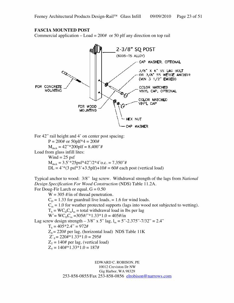
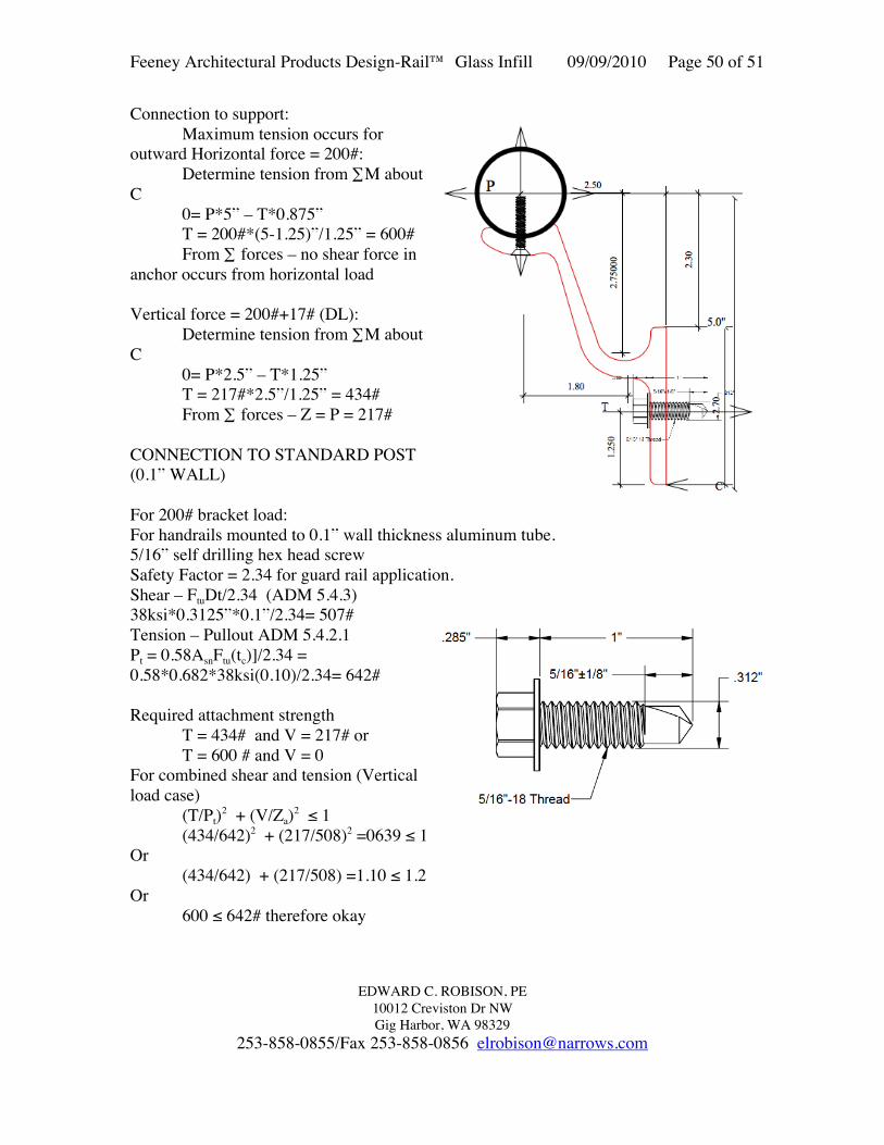
FASCIA MOUNTED POSTCommercial application – Load = 200# or 50 plf any direction on top rail

For 42” rail height and 4’ on center post spacing:P = 200# or 50plf*4 = 200#Mdeck = 42”*200plf = 8,400”#

Load from glass infill lites:Wind = 25 psfMdeck = 3.5’*25psf*42”/2*4’o.c. = 7,350”#DL = 4’*(3 psf*3’+3.5plf)+10# = 60# each post (vertical load)

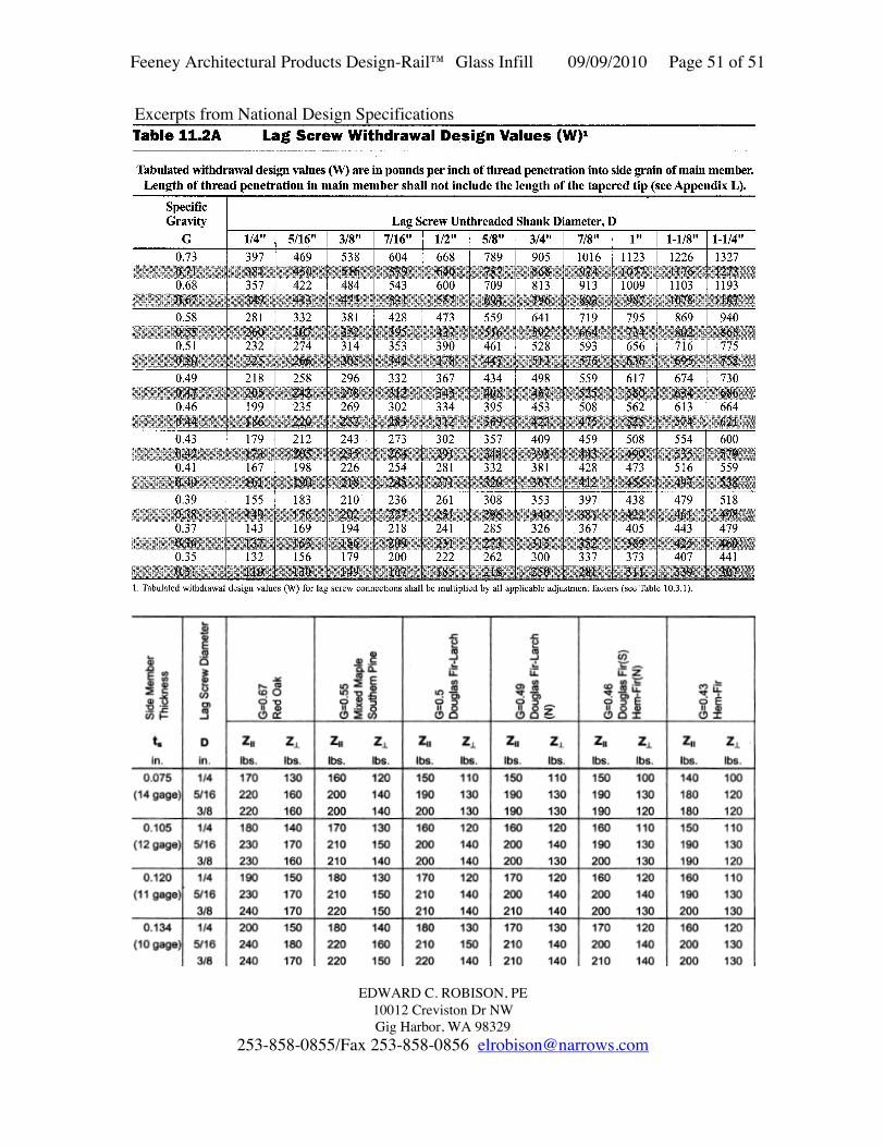
Typical anchor to wood: 3/8” lag screw. Withdrawal strength of the lags from NationalDesign Specification For Wood Construction (NDS) Table 11.2A.For Doug-Fir Larch or equal, G = 0.50

W = 305 #/in of thread penetration.CD = 1.33 for guardrail live loads, = 1.6 for wind loads.Cm = 1.0 for weather protected supports (lags into wood not subjected to wetting).Tb = WCDCmlm = total withdrawal load in lbs per lagW’= WCDCm =305#/”*1.33*1.0 = 405#/in

Lag screw design strength – 3/8” x 5” lag, lm = 5”-2.375”-7/32” = 2.4”Tb = 405*2.4” = 972#Zll = 220# per lag, (horizontal load) NDS Table 11K Z’ll = 220#*1.33*1.0 = 295#ZT = 140# per lag, (vertical load)ZT = 140#*1.33*1.0 = 187#

Feeney Architectural Products Design-Rail™ Glass Infill 09/09/2010 Page 24 of 51

EDWARD C. ROBISON, PE10012 Creviston Dr NWGig Harbor, WA 98329

253-858-0855/Fax 253-858-0856 [email protected]

Anchors to be minimum of 7” center tocenter and post shall extend 1-1/2” belowbottom anchor.

From ∑M about endM = (8.5”*T+1.5”*1.5/8.5*T) = 8.76”TAllowable post moment

Ma=972#*8.76” = 8,515”#For 3/8” lag screw okay for 36” rail height

For 3/8” carriage bolts:Allowable load per bolt = 0.11 in2*20

ksi = 2,200#For bearing on 2” square bearing

plate – area = 3.8 in2

Pb = 3.8 in2*1.19*405*1.33 = 2,436#Ma = 2,200#*8.76” = 19,272”#

(exceeds post strength)

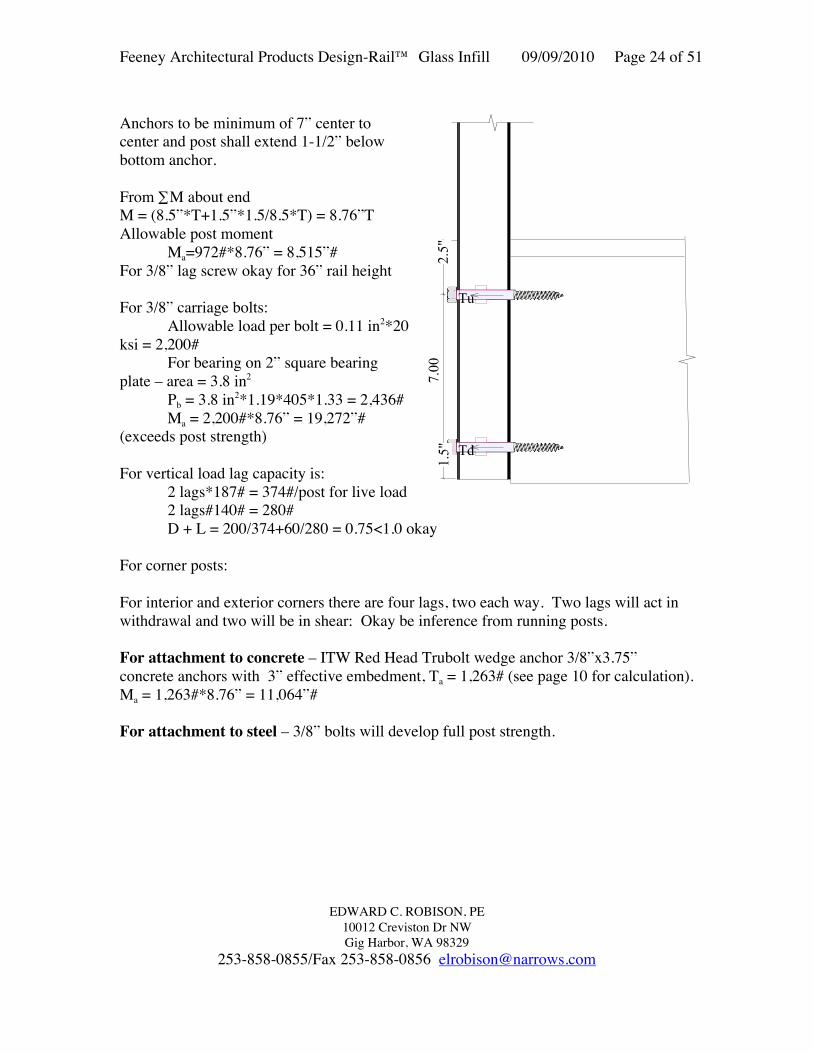
For vertical load lag capacity is:2 lags*187# = 374#/post for live load2 lags#140# = 280#D + L = 200/374+60/280 = 0.75<1.0 okay

For corner posts:

For interior and exterior corners there are four lags, two each way. Two lags will act inwithdrawal and two will be in shear: Okay be inference from running posts.

For attachment to concrete – ITW Red Head Trubolt wedge anchor 3/8”x3.75”concrete anchors with 3” effective embedment, Ta = 1,263# (see page 10 for calculation).Ma = 1,263#*8.76” = 11,064”#

For attachment to steel – 3/8” bolts will develop full post strength.

7 .0 0

Tu

Td1.5"

2.5"

Feeney Architectural Products Design-Rail™ Glass Infill 09/09/2010 Page 25 of 51

EDWARD C. ROBISON, PE10012 Creviston Dr NWGig Harbor, WA 98329

253-858-0855/Fax 253-858-0856 [email protected]

ALTERNATIVE FASCIA ATTACHMENT CONFIGURATIONS:

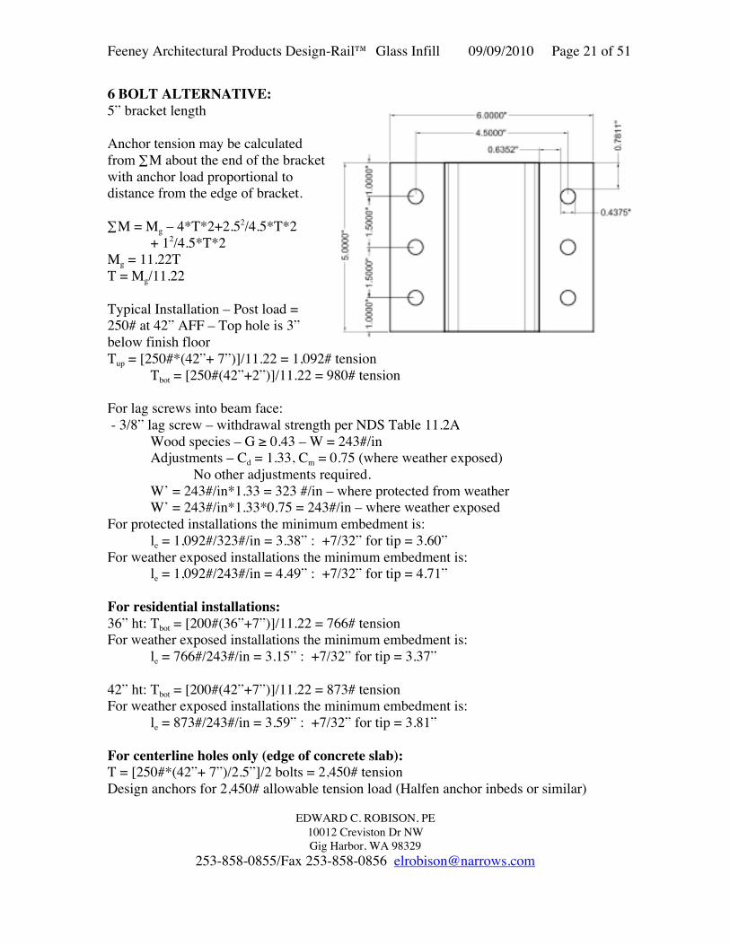
To 6x wood fascia:3 Bolt pattern – 1” from top and bottom and atcenter:∑M = Mg – 4.5*T+2.752/4.5*T + 12/4.5*TMg = 6.4TT = Mg/6.4For 36” residential guard:T = (36”+7”)*200#/6.4 = 1,344#Exceeds 3/8” lag screw capacity Requires use ofthru-bolts/carriage bolts.For 42” residential guard:T = (42”+7”)*200#/6.4 = 1,531#Exceeds 3/8” lag screw capacity Requires use of thru-bolts/carriage bolts.

Moment capacity of carriage bolts: Ta = 2,200#Ma = 2,200#*6.4” = 14,080”# - develops full post strength.

To 8x wood fasciaFor (4) 3/8” lag screw patternLag screws at 1” and 1.75” from top and bottom:∑M = Mg – 6.5*T+5.752/6.5*TMg = 11.59TT = Mg/11.59For 36” residential guard:T = (36”+9”)*200#/11.59 = 777#For weather exposed installations the minimum embedment is:

le = 777#/243#/in = 3.20” : +7/32” for tip = 3.42”

For 42” residential guard:T = (42”+9”)*200#/11.5 = 887#For weather exposed installations the minimum embedment is:

le = 887#/243#/in = 3.65” : +7/32” for tip = 3.87”

For (2) 3/8” carriage bolt alternative:Moment capacity of carriage bolts: Ta = 2,200#Ma = 2,200#*6” = 13,200”# - develops full post strength.

Feeney Architectural Products Design-Rail™ Glass Infill 09/09/2010 Page 26 of 51

EDWARD C. ROBISON, PE10012 Creviston Dr NWGig Harbor, WA 98329

253-858-0855/Fax 253-858-0856 [email protected]

To 8” nominal slab edge (7.5”).ITW Red Head Trubolt wedge anchor 3/8”x3.75”concrete anchors with 3” effective embedment.Anchor strength based on ESR-2251Minimum conditions used for the calculations:f’c ≥ 3,000 psiedge distance =2.5” spacing = 2.5”h = 3.0”: embed depthFor concrete breakout strength:ANcg= (1.5*3*2)*7.5 = 67.5 in2 2 anchorsANco= 9*32 = 81 in2

Ca,min = 1.5” (ESR-2251 Table 3)Cac = 5.25” (ESR-2251 Table 3)ϕed,N = 1.0ϕc,N = (use 1.0 in calculations with k = 24)ϕcp,N= 0.7+0.3*[2.5/(1.5*3)] = 0.87Nb = 24*1.0*√3000*3.01.5 = 6,830#Ncb = 69.5/81*1.0*1.0*0.87*6,830 = 5,098 ≤ 2*3,469based on concrete breakout strength.Determine allowable moment load on anchor groupTs = 0.65*5,098#/1.6*5” = 11,391”#Develops the full post strength.

Feeney Architectural Products Design-Rail™ Glass Infill 09/09/2010 Page 27 of 51

EDWARD C. ROBISON, PE10012 Creviston Dr NWGig Harbor, WA 98329

253-858-0855/Fax 253-858-0856 [email protected]

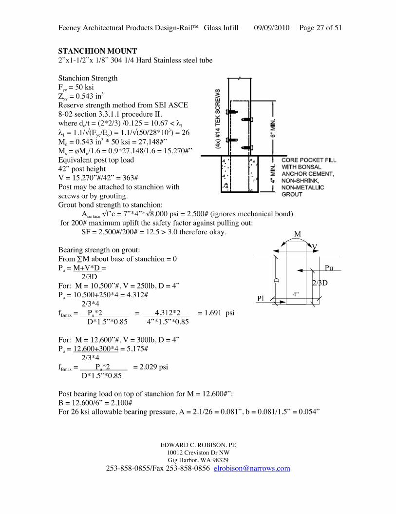
STANCHION MOUNT2”x1-1/2”x 1/8” 304 1/4 Hard Stainless steel tube

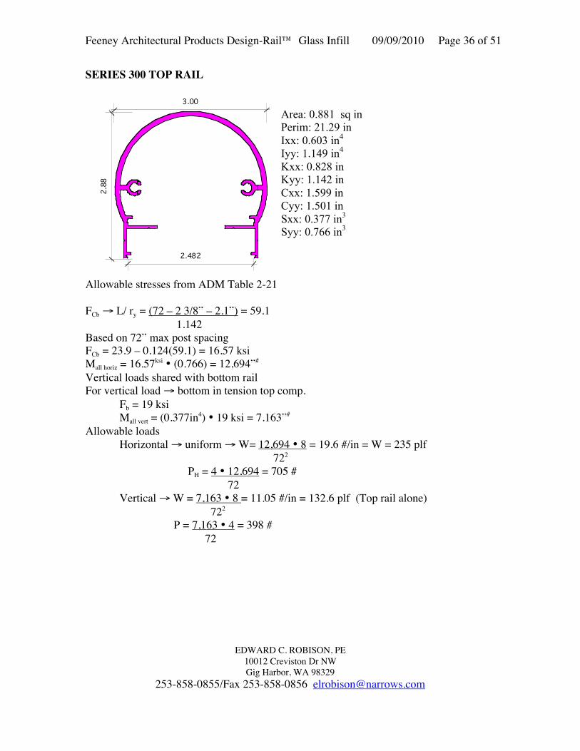
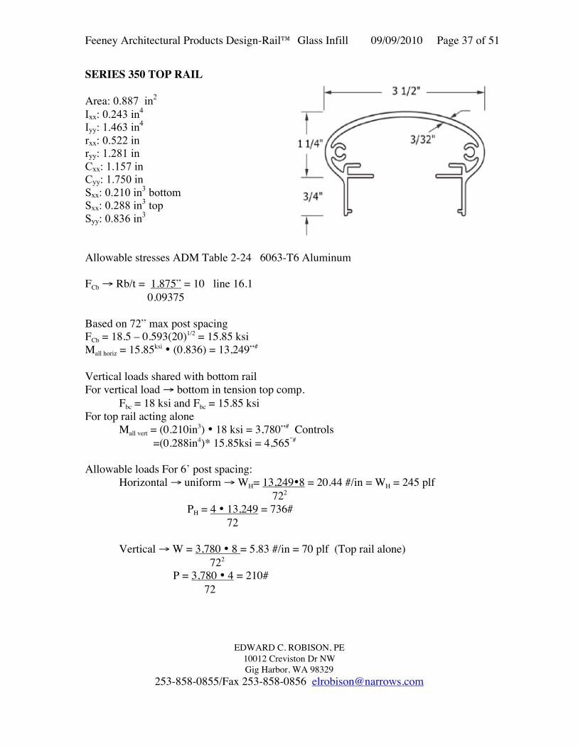
Stanchion StrengthFyc = 50 ksiZyy = 0.543 in3

Reserve strength method from SEI ASCE8-02 section 3.3.1.1 procedure II.where dc/t = (2*2/3) /0.125 = 10.67 < λ1

λ1 = 1.1/√(Fyc/Eo) = 1.1/√(50/28*103) = 26Mn = 0.543 in3 * 50 ksi = 27,148#”Ms = øMn/1.6 = 0.9*27,148/1.6 = 15,270#”Equivalent post top load42” post heightV = 15,270”#/42” = 363#Post may be attached to stanchion withscrews or by grouting.Grout bond strength to stanchion:

Asurface √f’c = 7”*4”*√8,000 psi = 2,500# (ignores mechanical bond) for 200# maximum uplift the safety factor against pulling out:

SF = 2,500#/200# = 12.5 > 3.0 therefore okay.

Bearing strength on grout:From ∑M about base of stanchion = 0Pu = M+V*D =

2/3DFor: M = 10,500”#, V = 250lb, D = 4”Pu = 10,500+250*4 = 4,312#

2/3*4fBmax = Pu*2 = 4,312*2 = 1,691 psi

D*1.5”*0.85 4”*1.5”*0.85

For: M = 12,600”#, V = 300lb, D = 4”Pu = 12,600+300*4 = 5,175#

2/3*4fBmax = Pu*2 = 2,029 psi D*1.5”*0.85

Post bearing load on top of stanchion for M = 12,600#”:B = 12,600/6” = 2,100#For 26 ksi allowable bearing pressure, A = 2.1/26 = 0.081”, b = 0.081/1.5” = 0.054”

4"

V

M

Pu

Pl

2/3DD

Feeney Architectural Products Design-Rail™ Glass Infill 09/09/2010 Page 28 of 51

EDWARD C. ROBISON, PE10012 Creviston Dr NWGig Harbor, WA 98329

253-858-0855/Fax 253-858-0856 [email protected]

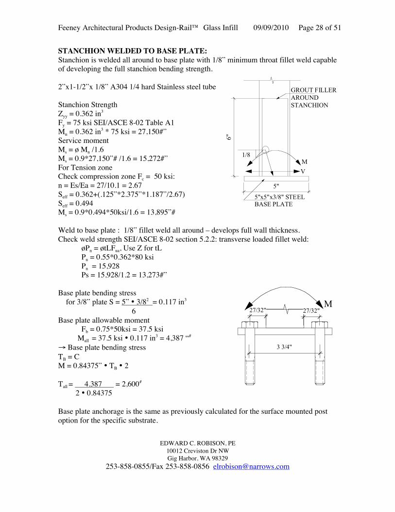
STANCHION WELDED TO BASE PLATE:Stanchion is welded all around to base plate with 1/8” minimum throat fillet weld capableof developing the full stanchion bending strength.

2”x1-1/2”x 1/8” A304 1/4 hard Stainless steel tube

Stanchion StrengthZyy = 0.362 in3

Fy = 75 ksi SEI/ASCE 8-02 Table A1Mn = 0.362 in3 * 75 ksi = 27,150#”Service momentMs = ø Mn /1.6Ms = 0.9*27,150”# /1.6 = 15,272#”For Tension zoneCheck compression zone Fc = 50 ksi:n = Es/Ea = 27/10.1 = 2.67Seff = 0.362+(.125”*2.375”*1.187”/2.67)Seff = 0.494Ms = 0.9*0.494*50ksi/1.6 = 13,895”#

Weld to base plate : 1/8” fillet weld all around – develops full wall thickness.Check weld strength SEI/ASCE 8-02 section 5.2.2: transverse loaded fillet weld:

øPn = øtLFua, Use Z for tLPn = 0.55*0.362*80 ksiPn = 15,928Ps = 15,928/1.2 = 13,273#”

Base plate bending stress for 3/8” plate S = 5” • 3/82 = 0.117 in3

6Base plate allowable moment

Fb = 0.75*50ksi = 37.5 ksi Mall = 37.5 ksi • 0.117 in3 = 4,387 “#

→ Base plate bending stressTB = CM = 0.84375” • TB • 2

Tall = 4.387 = 2,600#

2 • 0.84375

Base plate anchorage is the same as previously calculated for the surface mounted postoption for the specific substrate.

27/32" 27/32"M

3 3/4"

5"

6"

GROUT FILLERAROUND STANCHION

V

M

5"x5"x3/8" STEEL BASE PLATE

1/8

Feeney Architectural Products Design-Rail™ Glass Infill 09/09/2010 Page 29 of 51

EDWARD C. ROBISON, PE10012 Creviston Dr NWGig Harbor, WA 98329

253-858-0855/Fax 253-858-0856 [email protected]

POOL FENCE/WIND FENCE OPTION

The Design-Rail may be used to construct pool fences or wind walls.

Maximum allowable height for 48” on center post spacing:

For any of the detailed anchorage to wood or surface mounted to any substrate or directfascia mounted (two bolts):Ma = 9,600”#Live load is 50 plf at 42” above finish floor or 200# at 42” above finish floor.

For 25 psf loading:Maximum post height for 4’ o.c. post spacing:Ha = √(2*800’#)/(25psf*4’)) = 4’Required post spacing for 25 psf loading and 5’ post height:Ha = (2*800’#)/(25psf*52)) = 2.56’ = 2’ 7”

For 20 psf loading:Maximum post height for 4’ o.c. post spacing:Ha = √(2*800’#)/(20psf*4’)) = 4.47’Required post spacing for 25 psf loading and 5’ post height:Ha = (2*800’#)/(20psf*52)) = 3.2’ = 2’ 7”

Maximum allowable wind load for 5’ post height and 4’ on center post spacing:W = 800’#/(4’*5’2/2) = 16 psf85 mph exposure C, Kzt = 1.0

For core mounted posts or steel stanchion mounted to concrete or steel or fasciamounted with fascia bracket:25 psf wind loading:Maximum post height for 4’ o.c. post spacing:Ha = √(2*1,150’#)/(25psf*4’)) = 4.78’ 4’ 9”Required post spacing for 25 psf loading and 5’ post height:Ha = (2*1,150’#)/(25psf*52)) = 3.68’ = 3’ 8”

Maximum allowable wind load for 5’ post height and 4’ on center post spacing:W = 1,150’#/(4’*5’2/2) = 23 psf105 mph exposure C, Kzt = 1.0

Feeney Architectural Products Design-Rail™ Glass Infill 09/09/2010 Page 30 of 51

EDWARD C. ROBISON, PE10012 Creviston Dr NWGig Harbor, WA 98329

253-858-0855/Fax 253-858-0856 [email protected]

SERIES 100 TOP RAIL

Butts into postAlloy 6063 – T6 AluminumAllowable Stress: ADM Table 2-24

FT = 15 ksi

FC → 6’ span

2 Lb SC = 2•72” • 0.246(IyJ) (0.295*1.53)1/2

= 52.7<130 thereforeFc = 15 ksi

Allowable Moments Horiz.= 0.295in3 15 ksi =

4,425#” = 368.75 #’Vertical load = 0.246in3 15 ksi = 3,690#” = 307.5 #’

Maximum allowable load for 72” o.c. post spacing - verticalW = 3,690”#*8/(69.625”2) = 6.09 pli = 73.1 plfP = 3,690”#*4/69.625” = 212#

Maximum span without load sharing, P = 200# - verticalS = 3,690”#*4/200# = 73.8” clearMax post spacing =73.8”+2.375” = 76.175”

For horizontal loading rail strength is greater and therefore okay by inference.

Maximum allowable load for 72” length horizontal loadW = 4,425”#*8/722 = 6.8 pli = 81.9 plfP = 4,425”#*4/72” = 245.8#

Maximum span for P = 200# and W = 50 plf horizontal loadW = √(368.75#’*8/50) = 7.68’ = 7’ 8.5”P = 368.75#’*4/200 = 7.375’ = 7’3.5” controls

Feeney Architectural Products Design-Rail™ Glass Infill 09/09/2010 Page 31 of 51

EDWARD C. ROBISON, PE10012 Creviston Dr NWGig Harbor, WA 98329

253-858-0855/Fax 253-858-0856 [email protected]

SERIES 150 TOP RAILA = 0.676 in2

Ixx = 0.1970 in4

Iyy = 0.2263 in4

Sxx = 0.1522 in3

Syy = 0.2263 in3

rxx = 0.540 inryy = 00579 inAlloy 6063 – T6 AluminumAllowable Stress: ADM Table 2-24FT = 18 ksi

FC → 6’ spanRb/t = 0.3/0.065 = 4.6 < 35Fc = 18 ksi for horizontal loadsd/t = 0.75”/0.65 = 1.15 < 15Fc = 20 ksi for vertical loads

Allowable Moments Horiz.= 0.2263in3 18 ksi = 4,073”# = 339.45’#Vertical load = 0.1522in3 18 ksi = 2,739.6”# = 228.3#’

Maximum allowable load for 72” o.c. post spacing - verticalW = 2,739.6”#*8/(69.625”2) = 4.52 pli = 54 plfP = 2,793.6”#*4/69.625” = 160.5#

Maximum span without load sharing, P = 200# - verticalS = 2,793.6”#*4/200# = 55.87” clearMax post spacing =55.87”+2.375” = 58 1/4”

With loading sharing with bottom rail – load transferred by glass 200# concentrated loadmay be safely supported with 6’ on center post spacing.

Maximum allowable load for 72” length horizontal loadW = 4,073”#*8/69.6252 = 6.7 pli = 80.6 plfP = 4,073”#*4/69.625” = 234#

Maximum post spacing is 6’.

Feeney Architectural Products Design-Rail™ Glass Infill 09/09/2010 Page 32 of 51

EDWARD C. ROBISON, PE10012 Creviston Dr NWGig Harbor, WA 98329

253-858-0855/Fax 253-858-0856 [email protected]

SERIES 100 – UNIVERSAL BOTTOM RAIL

Rail Properties:6063-T6 AluminumIxx = 0.102 in4, Sxx = 0.101 in3Iyy = 0.164 in4, Syy = 0.193 in3rxx = 0.476”, ryy = 0.603”

For 72” on center posts; L = 72”-2.375”-1”x2 = 67.625” ; Lb= 1/2L = 33.81”Lb/ry = 33.81”/0.603 = 56 From ADM Table 2-24Fbc = 16.7-0.073 56 = 12.6 ksi

Allowable Moments Horiz.= 0.193in3 12.6 ksi =2,432”#Maximum allowable load for 72” o.c. post spacing

W = 2,432”#*8/(67.625”2) = 4.25 pli = 51 plfP = 2,432”#*4/67.625” = 144#

Max span for 50 plf load = (8*2,432/(50/12))1/2 = 68.33” clear span

Max span for 200# concentrated load:L = 4*2,432”#/200# = 48.6”

Rail fasteners -Bottom rail connection block to post #101.5” 55 PHP SMS ScrewCheck shear @ post (6005-T5)

2x Fupostx dia screw x Post thickness x SF

V= 238 ksi 0.1697” 0.10” 1 = 3 (FS)

V = 430#/screw

Since minimum of 2 screws used for eachAllowable load = 2 430# = 860#

Rail Connection to RCB

2 screws each end #8 Tek screw to 6063-T6V= 238 ksi 0.1309” 0.07” 1 = 232# 3 (FS)

Feeney Architectural Products Design-Rail™ Glass Infill 09/09/2010 Page 33 of 51

EDWARD C. ROBISON, PE10012 Creviston Dr NWGig Harbor, WA 98329

253-858-0855/Fax 253-858-0856 [email protected]

SERIES 100/150 TOP RAIL CONNECTION TO POST FACE:Use RCB attached to post with 2 #10 screws same as bottom rail.

V= 238 ksi 0.19” 0.10” 1 = 481#/screw 3 (FS)

Since minimum of 2 screwsused for eachAllowable load =2 481# = 962#

The connection block can becut square for use inhorizontal rail applications orangled for use in slopedapplications such as along stairs or ramps.

Feeney Architectural Products Design-Rail™ Glass Infill 09/09/2010 Page 34 of 51

EDWARD C. ROBISON, PE10012 Creviston Dr NWGig Harbor, WA 98329

253-858-0855/Fax 253-858-0856 [email protected]

INTERMEDIATE POST FITTING – SERIES 100/150Used for intermediate posts along stairwaysFitting locks into top of post with #8 Tek screws:

Maximum load on fitting is 300#6’ post spacing * 50 plf = 300#

Shear resisted by direct bearing betweenfitting and postarea = 2.175”*0.1875 = 0.408 in2

Bearing pressure = 300#/.408 = 736 psi

Moment of fitting to post:This is an intermediate post with

rotation of top rail restrained at rail ends.Moment of fitting is created by

eccentricity between bottom of top rail and top of post: e = 0.425”M = 300# * (0.425”) = 127.5#”

#8 Tek screws:Shear strength = V= 238 ksi 0.1309” 0.07” 1 = 232# 3 (FS)Moment capacityM= 232#*2.375” = 551#”

Feeney Architectural Products Design-Rail™ Glass Infill 09/09/2010 Page 35 of 51

EDWARD C. ROBISON, PE10012 Creviston Dr NWGig Harbor, WA 98329

253-858-0855/Fax 253-858-0856 [email protected]

SERIES 200 TOP RAIL

Area: 0.887 sq in

Ixx: 0.254 in4

Iyy: 1.529 in4

rxx: 0.536 inryy: 1.313 inCxx: 1.194 inCyy: 1.750 inSxx: 0.213 in3 bottomSxx: 0.457 in3 topSyy: 0.874 in3

6063-T6 Aluminum alloy from ADM Table 2-24For 72” on center posts; L = 72”-2.375”-1”x2 = 67.625” ; kLb = 1/2L = 33.81”Fbc = 16.7-0.073 33.81 = 14.82 ksi 1.313Ft = 15 ksiAllowable Moments Horiz.= 0.874in3 14.82 ksi = 12,953#” = 1,079#’

Vertical load = 0.457in3 14.82 ksi = 6,773#” top compressionor = 0.213in3 15 ksi = 3,195#” controls vertical- bottom tension

Maximum allowable load for 72” o.c. post spacing - verticalW = 3,195”#*8/(67.625”2) = 5.59 pli = 67 plfP = 3,195”#*4/67.625” = 189# Load sharing with bottom rail required for 6 foot

post spacing. Glass infill will transfer loads from top rail to bottom rail and providerequired additional support.

With load sharing maximum span is 6’.

Maximum span without load sharing, P = 200#S = 3,195#”*4/200# = 63.9” clearMax post spacing =63.9”+2.375” = 66-1/4”, 5’ 6-1/4”

For horizontal load, maximum span for 50 plf loadL = (8Ma/50plf)1/2 = (8*1,079/50plf)1/2 = 13.14’

for 200# concentrated load L = (4M/200#) = (4*1,079/200plf)= 21.58’deflection limits will limit span to 6’.

Feeney Architectural Products Design-Rail™ Glass Infill 09/09/2010 Page 36 of 51

EDWARD C. ROBISON, PE10012 Creviston Dr NWGig Harbor, WA 98329

253-858-0855/Fax 253-858-0856 [email protected]

SERIES 300 TOP RAIL

Area: 0.881 sq inPerim: 21.29 inIxx: 0.603 in4

Iyy: 1.149 in4

Kxx: 0.828 inKyy: 1.142 inCxx: 1.599 inCyy: 1.501 inSxx: 0.377 in3

Syy: 0.766 in3

Allowable stresses from ADM Table 2-21

FCb → L/ ry = (72 – 2 3/8” – 2.1”) = 59.1 1.142

Based on 72” max post spacingFCb = 23.9 – 0.124(59.1) = 16.57 ksiMall horiz = 16.57ksi • (0.766) = 12,694”#

Vertical loads shared with bottom railFor vertical load → bottom in tension top comp.

Fb = 19 ksiMall vert = (0.377in4) • 19 ksi = 7.163”#

Allowable loadsHorizontal → uniform → W= 12,694 • 8 = 19.6 #/in = W = 235 plf

722

PH = 4 • 12,694 = 705 # 72

Vertical → W = 7,163 • 8 = 11.05 #/in = 132.6 plf (Top rail alone) 722

P = 7,163 • 4 = 398 # 72

3.002.88

2.482

Feeney Architectural Products Design-Rail™ Glass Infill 09/09/2010 Page 37 of 51

EDWARD C. ROBISON, PE10012 Creviston Dr NWGig Harbor, WA 98329

253-858-0855/Fax 253-858-0856 [email protected]

SERIES 350 TOP RAIL

Area: 0.887 in2

Ixx: 0.243 in4

Iyy: 1.463 in4

rxx: 0.522 inryy: 1.281 inCxx: 1.157 inCyy: 1.750 inSxx: 0.210 in3 bottomSxx: 0.288 in3 topSyy: 0.836 in3

Allowable stresses ADM Table 2-24 6063-T6 Aluminum

FCb → Rb/t = 1.875” = 10 line 16.1 0.09375

Based on 72” max post spacingFCb = 18.5 – 0.593(20)1/2 = 15.85 ksiMall horiz = 15.85ksi • (0.836) = 13,249”#

Vertical loads shared with bottom railFor vertical load → bottom in tension top comp.

Fbc = 18 ksi and Fbc = 15.85 ksiFor top rail acting alone

Mall vert = (0.210in3) • 18 ksi = 3,780”# Controls=(0.288in4)* 15.85ksi = 4,565”#

Allowable loads For 6’ post spacing:Horizontal → uniform → WH= 13,249•8 = 20.44 #/in = WH = 245 plf

722

PH = 4 • 13,249 = 736# 72

Vertical → W = 3,780 • 8 = 5.83 #/in = 70 plf (Top rail alone) 722

P = 3,780 • 4 = 210# 72

Feeney Architectural Products Design-Rail™ Glass Infill 09/09/2010 Page 38 of 51

EDWARD C. ROBISON, PE10012 Creviston Dr NWGig Harbor, WA 98329

253-858-0855/Fax 253-858-0856 [email protected]

SERIES 400 TOP RAIL COMPOSITE MATERIAL ORAlloy 6063 – T6 Aluminum

Ixx: 0.0138 in4; Iyy: 0.265 in4

Cxx: 0.573 in; Cyy: 1.344 inSxx: 0.024 in3; Syy: 0.197 in3

Wood – varies G≥ 0.432”x4” nominalIxx: 0.984 in4; Iyy: 5.359 in4

Cxx: 0.75 in; Cyy: 1.75 inSxx: 1.313 in3; Syy: 3.063 in3

Allowable Stress for aluminum: ADMTable 2-24FT = 15 ksiFC → 6’ spanRail is braced by wood At 16” o.c. and legs have stiffeners thereforeFc = 15 ksi

For wood use allowable stress from NDS Table 4A for lowest strength wood that may beused: Fb = 725 psi (mixed maple #1), CD =1.33, CF = 1.5

F’b = 725*1.33*1.5 = 1,445 psiF’b = 725*1.33*1.5*1.1 = 1,590 psi for flat use (vertical loading)

Composite action between aluminum and wood:n = Ea/Ew = 10.1/1.1 = 9.18

The limiting stress on the aluminum = 9.18*1,445 psi = 13,267 psi < 15 ksi

Allowable Moments Horiz.= 0.197in3 13267 psi +3.063 in3*1445psi = 7040”#Vertical load = 0.024in3 13267 ksi +1.313*1,590= 2,405”#

Maximum allowable load for 72” o.c. post spacing - Horizontal loadW = 7,040”#*8/(69.625”2) = 11.6 pli = 139 plfP = 7,040”#*4/69.625” = 404#

Maximum span without load sharing, P = 200# or 50 lf - Vertical loadS = 2,405”#*4/200# = 48.1” clearMax post spacing =48.1”+2.375” = 50.475”

COMPOSITES: Composite materials, plastic lumber or similar may be used providedthat the size and strength is comparable to the wood.

1/16"3/4"

2 11/16"

WOOD CAP

SERIES 400 CAP RAIL

POST

Feeney Architectural Products Design-Rail™ Glass Infill 09/09/2010 Page 39 of 51

EDWARD C. ROBISON, PE10012 Creviston Dr NWGig Harbor, WA 98329

253-858-0855/Fax 253-858-0856 [email protected]

TOP RAIL VERTICAL LOAD – LOAD SHARING

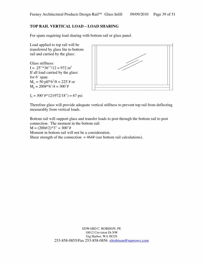
For spans requiring load sharing with bottom rail or glass panel.

Load applied to top rail will betransferred by glass lite to bottomrail and carried by the glass:

Glass stiffness:I = .25”*36”3/12 = 972 in4

If all load carried by the glass:for 6’ span:Mw = 50 plf*62/8 = 225’# orMp = 200#*6’/4 = 300’#

fb = 300’#*12/(972/18”) = 67 psi

Therefore glass will provide adequate vertical stiffness to prevent top rail from deflectingmeasurably from vertical loads.

Bottom rail will support glass and transfer loads to post through the bottom rail to postconnection. The moment in the bottom rail:M = (200#/2)*3” = 300”#Moment in bottom rail will not be a consideration.Shear strength of the connection = 464# (see bottom rail calculations).

Feeney Architectural Products Design-Rail™ Glass Infill 09/09/2010 Page 40 of 51

EDWARD C. ROBISON, PE10012 Creviston Dr NWGig Harbor, WA 98329

253-858-0855/Fax 253-858-0856 [email protected]

GLASS INFILL INSERT:Series 200, 300, 350 and 400 top railsEither infill option may be used as strength isequivalent for each style.

Insert channel for glassIyy = 0.156 in4 Ixx = 0.023 in4

Syy = 0.125 in3 Sxx = 0.049 in4

Insert compression locks into top railHorizontal forces transferred between insert and top railby direct bearing on locking tabs.

Bearing area = 1/8” widthAllowable bearing load will be controlled byspreading of top railCheck significance of circumferential stress:

R/t = 3”/0.09375 = 32 > 5 therefore canassume plane bending and error will be minimal

M = 2.08”*WMall = S*FbFb = 20 ksi for flat element bending in own

plane, ADM Table 2-24S = 12”/ft*(0.094)2/6 = 0.0177 in3

Wall = Mall/2.08” = (S* Fb)/2.08” = (0.0177in3*20 ksi)/2.08” = 170 plf

For 36” panel height – 1/2 will be tributary to top rail:Maximum live load = 170 plf/(3’/2) = 113 psf.

Check deflection:∆ = WL3/(3EI)I = 12”*0.093753/12 = .000824 in4∆ = 170plf*2.08”3/(3*10.1x106*.000824) = 0.06”

The required deflection to cause the infill to disengage: 0.05”Reduce allowable load to limit total deflection:

0.05/0.06*113 plf = 94 plf

Maximum horizontal load on glass infill is 94 plf

INFILL LOADRESTRAINEDAT POSTS

Mi

Feeney Architectural Products Design-Rail™ Glass Infill 09/09/2010 Page 41 of 51

EDWARD C. ROBISON, PE10012 Creviston Dr NWGig Harbor, WA 98329

253-858-0855/Fax 253-858-0856 [email protected]

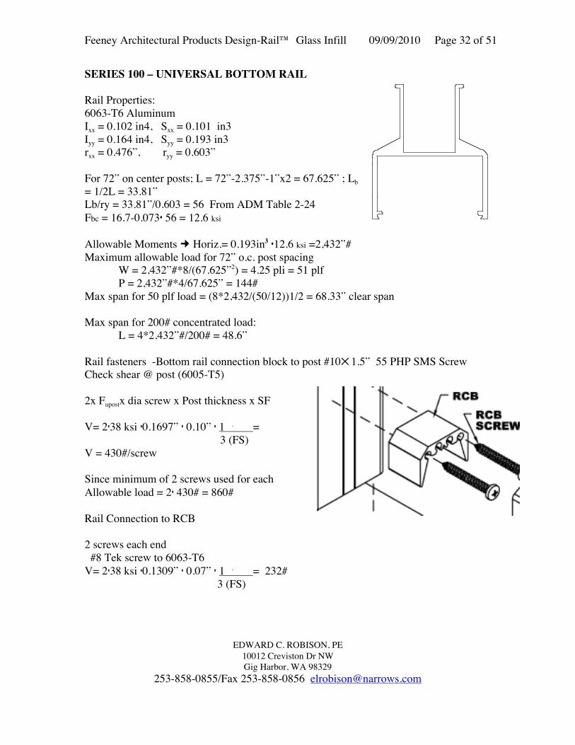
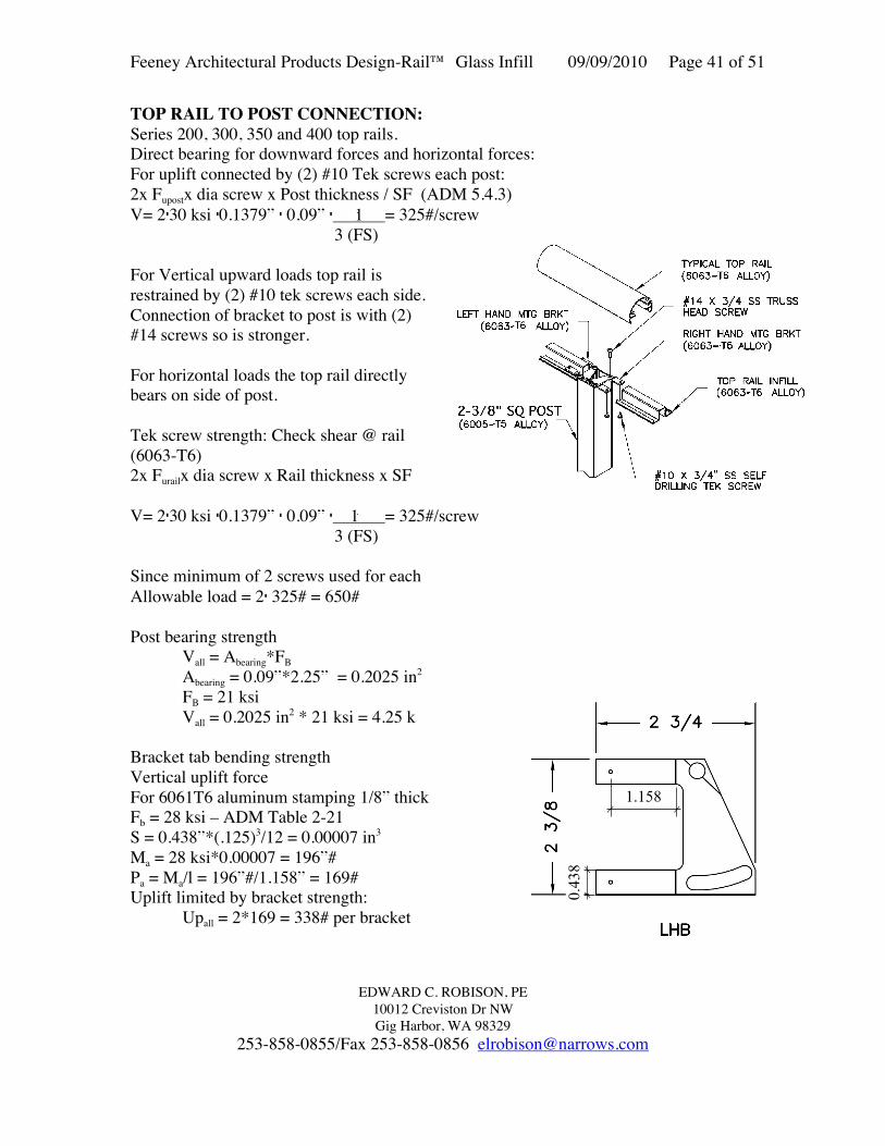
TOP RAIL TO POST CONNECTION:Series 200, 300, 350 and 400 top rails.Direct bearing for downward forces and horizontal forces:For uplift connected by (2) #10 Tek screws each post:2x Fupostx dia screw x Post thickness / SF (ADM 5.4.3)V= 230 ksi 0.1379” 0.09” 1 = 325#/screw 3 (FS)

For Vertical upward loads top rail isrestrained by (2) #10 tek screws each side.Connection of bracket to post is with (2)#14 screws so is stronger.

For horizontal loads the top rail directlybears on side of post.

Tek screw strength: Check shear @ rail(6063-T6)2x Furailx dia screw x Rail thickness x SF

V= 230 ksi 0.1379” 0.09” 1 = 325#/screw 3 (FS)

Since minimum of 2 screws used for eachAllowable load = 2 325# = 650#

Post bearing strengthVall = Abearing*FBAbearing = 0.09”*2.25” = 0.2025 in2

FB = 21 ksiVall = 0.2025 in2 * 21 ksi = 4.25 k

Bracket tab bending strengthVertical uplift forceFor 6061T6 aluminum stamping 1/8” thickFb = 28 ksi – ADM Table 2-21S = 0.438”*(.125)3/12 = 0.00007 in3

Ma = 28 ksi*0.00007 = 196”#Pa = Ma/l = 196”#/1.158” = 169#Uplift limited by bracket strength:

Upall = 2*169 = 338# per bracket

1.158

0.438

Feeney Architectural Products Design-Rail™ Glass Infill 09/09/2010 Page 42 of 51

EDWARD C. ROBISON, PE10012 Creviston Dr NWGig Harbor, WA 98329

253-858-0855/Fax 253-858-0856 [email protected]

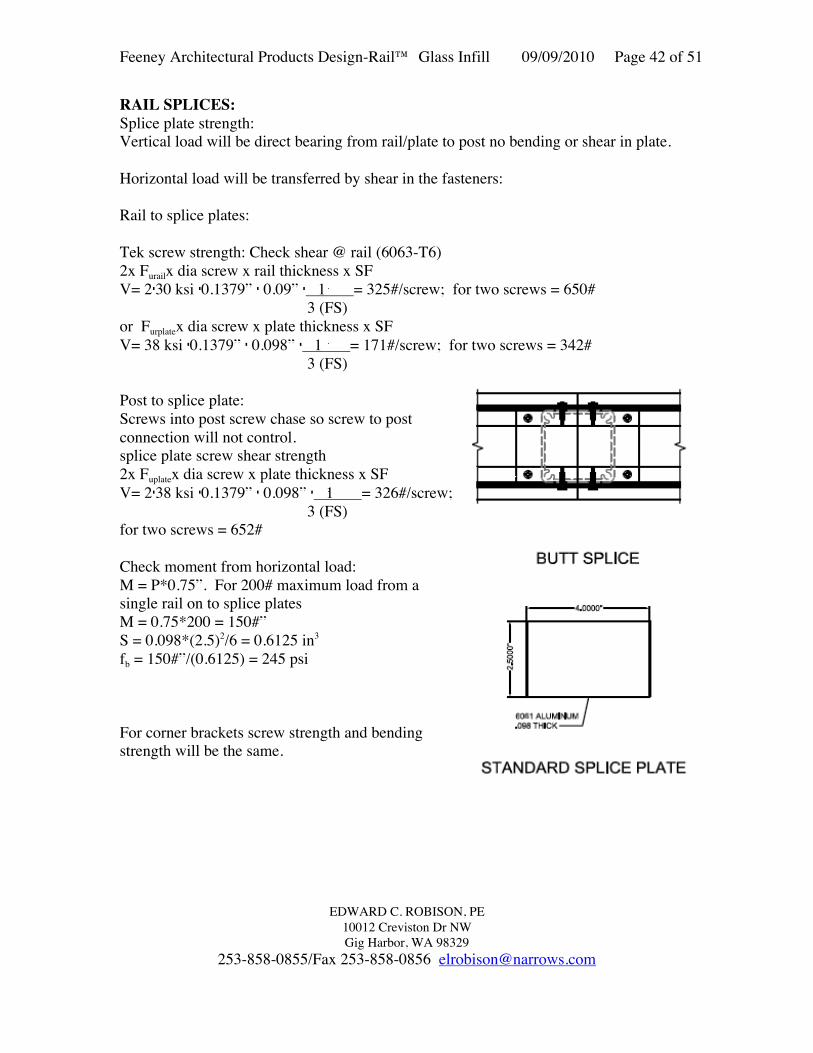
RAIL SPLICES:Splice plate strength:Vertical load will be direct bearing from rail/plate to post no bending or shear in plate.

Horizontal load will be transferred by shear in the fasteners:

Rail to splice plates:

Tek screw strength: Check shear @ rail (6063-T6)2x Furailx dia screw x rail thickness x SFV= 230 ksi 0.1379” 0.09” 1 = 325#/screw; for two screws = 650#

3 (FS)or Furplatex dia screw x plate thickness x SFV= 38 ksi 0.1379” 0.098” 1 = 171#/screw; for two screws = 342#

3 (FS)

Post to splice plate:Screws into post screw chase so screw to postconnection will not control.splice plate screw shear strength2x Fuplatex dia screw x plate thickness x SFV= 238 ksi 0.1379” 0.098” 1 = 326#/screw;

3 (FS)for two screws = 652#

Check moment from horizontal load:M = P*0.75”. For 200# maximum load from asingle rail on to splice platesM = 0.75*200 = 150#”S = 0.098*(2.5)2/6 = 0.6125 in3

fb = 150#”/(0.6125) = 245 psi

For corner brackets screw strength and bendingstrength will be the same.

Feeney Architectural Products Design-Rail™ Glass Infill 09/09/2010 Page 43 of 51

EDWARD C. ROBISON, PE10012 Creviston Dr NWGig Harbor, WA 98329

253-858-0855/Fax 253-858-0856 [email protected]

INTERMEDIATE RAIL

Ixx = 0.123 in4

Iyy = 0.177 in4

Sxx = 0.115 in3

Syy = 0.209 in3

rxx = 0.579 inryy = 0.695 in

Allowable stresses: ADM Table 2-24 6063-T6AluminumFt = 19 ksi For vertical loadsFCb → Rb/t = 1.25” = 0.33 line 16.1 FCb = 18 ksi

3.75Mall vert = 18ksi • (0.115) = 2,070”#

For horizontal loads:Ft = 15 ksi For vertical loadsFCb → Lb/ry = 35” = 50.4 line 11

0.695Based on 72” max post spacingFCb = (16.7-0.073*50.4) ksi = 13.0 ksiMall horiz = 13ksi • (0.209) = 2,717”#

For intermediate rail acting aloneAllowable loads

Horizontal → uniform → WH= 2,717•8 = 4.44 #/in = WH = 53 plf 702

PH = 4 • 2,717 = 155 # Not used for top rail 50# conc load appl. 70

Vertical → W = 2070 • 8 = 3.38 #/in = 40.6 plf (Top rail alone) 702

P = 2070 • 4 = 118# Not used for top rail 50# conc load appl. 70

Maximum wind load for 3’6” lite height, 1’9” tributary widthWmax = 53/1.75 = 30.3 plf

Maximum span for 200# concentrated load:L = 2,717*4/200# = 54”

May only be used as a top rail for single family residences with a maximum post spacingof 4’ 6”.

1.6875

1.75

t =0.062

Feeney Architectural Products Design-Rail™ Glass Infill 09/09/2010 Page 44 of 51

EDWARD C. ROBISON, PE10012 Creviston Dr NWGig Harbor, WA 98329

253-858-0855/Fax 253-858-0856 [email protected]

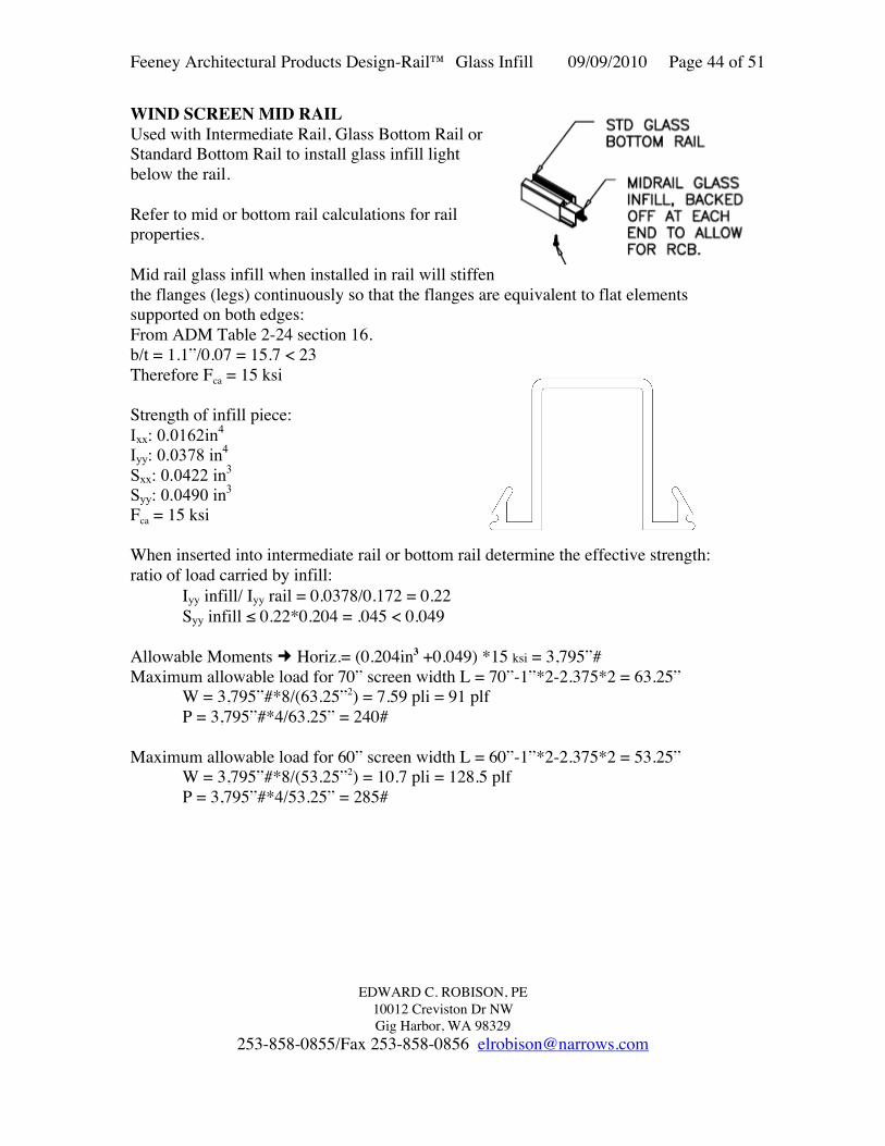
WIND SCREEN MID RAILUsed with Intermediate Rail, Glass Bottom Rail orStandard Bottom Rail to install glass infill lightbelow the rail.

Refer to mid or bottom rail calculations for railproperties.

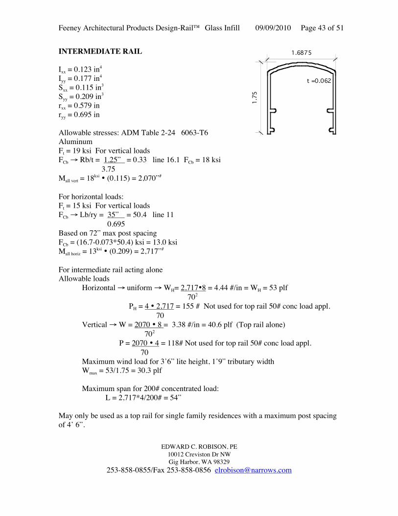
Mid rail glass infill when installed in rail will stiffenthe flanges (legs) continuously so that the flanges are equivalent to flat elementssupported on both edges:From ADM Table 2-24 section 16.b/t = 1.1”/0.07 = 15.7 < 23Therefore Fca = 15 ksi

Strength of infill piece:Ixx: 0.0162in4

Iyy: 0.0378 in4

Sxx: 0.0422 in3

Syy: 0.0490 in3

Fca = 15 ksi

When inserted into intermediate rail or bottom rail determine the effective strength:ratio of load carried by infill:

Iyy infill/ Iyy rail = 0.0378/0.172 = 0.22Syy infill ≤ 0.22*0.204 = .045 < 0.049

Allowable Moments Horiz.= (0.204in3 +0.049) *15 ksi = 3,795”#Maximum allowable load for 70” screen width L = 70”-1”*2-2.375*2 = 63.25”

W = 3,795”#*8/(63.25”2) = 7.59 pli = 91 plfP = 3,795”#*4/63.25” = 240#

Maximum allowable load for 60” screen width L = 60”-1”*2-2.375*2 = 53.25”W = 3,795”#*8/(53.25”2) = 10.7 pli = 128.5 plfP = 3,795”#*4/53.25” = 285#

Feeney Architectural Products Design-Rail™ Glass Infill 09/09/2010 Page 45 of 51

EDWARD C. ROBISON, PE10012 Creviston Dr NWGig Harbor, WA 98329

253-858-0855/Fax 253-858-0856 [email protected]

GLASS INFILL BOTTOM RAIL

Area: 0.3923 sq inPerim: 11.648 in

Ixx: 0.0869 in^4Iyy: 0.172 in^4Kxx: 0.472 inKyy: 0.662 inCxx: 1.0133 inCyy: 0.8435 inSxx: 0.0857 in^3 BottomSxx: 0.129 in^3 TopSyy: 0.204 in^3

For 72” on center posts; L = 72”-2.375”-1”x2 = 67.625” ; Lb = 1/2L = 33.81”Lb/ry = 33.81”/0.662 = 51.07 From ADM Table 2-24:Fbc = 16.7-0.073 51.07 = 12.97 ksi

Allowable Moments Horiz.= 0.204in3 12.97 ksi =2,646”#Maximum allowable load for 72” o.c. post spacing

W = 2,646”#*8/(67.625”2) = 4.63 pli = 55.5 plfP = 2,646”#*4/67.625” = 156.5#

Max span for 50 plf load =(8*2646/(50/12))1/2 = 71.28” clear spanRail fasteners -Bottom rail connection block topost #101.5” 55 PHP SMS Screw

Check shear @ post (6005-T5)2x Fupostx dia screw x Post thickness x SFV= 238 ksi 0.1697” 0.10” 1 =

3 (FS)V = 430#/screwSince minimum of 2 screws used for eachAllowable load = 2 430# = 860#

Rail Connection to RCB

2 screws each en #8 Tek screw to 6063-T6

2*30ksi0.1309”0.07” 1 = 232#/screw 3Allowable tension = 2*232 = 464#

OK

Feeney Architectural Products Design-Rail™ Glass Infill 09/09/2010 Page 46 of 51

EDWARD C. ROBISON, PE10012 Creviston Dr NWGig Harbor, WA 98329

253-858-0855/Fax 253-858-0856 [email protected]

STANDARD POST RAIL CONNECTION BLOCK

Can be used to connect top rails to 2-3/8” standard post face, wood posts, walls or otherend butt connection.

Top rail snaps over block and issecured with either silicone adhesiveor #8 tek screws.

Connection strength to post or wall:(2) #101.5” 55 PHP SMS Screw

Check shear @ post (6005-T5)Fupostx dia screw x Post thickness x SFEq 5.4.3-2V= 38 ksi 0.19” 0.1” 1 =

3 (FS)V = 240#/screw for standard post

Since minimum of 2 screws used for each, Allowable load = 2 240# = 480#For attachment to wood posts: Use Four #10 x2.5” screwsZll = 139# per screw (NDS Table 11M, G ≥ 0.43)Va = 4*139# = 556#

Standard RCB

Feeney Architectural Products Design-Rail™ Glass Infill 09/09/2010 Page 47 of 51

EDWARD C. ROBISON, PE10012 Creviston Dr NWGig Harbor, WA 98329

253-858-0855/Fax 253-858-0856 [email protected]

WALL MOUNT END CAPS

End cap is fastened to the top rail with2) #101” 55 PHP SMS Screws

2x Fupostx dia screw x Cap thickness x SFEq 5.4.3-2V= 2*38 ksi 0.19” 0.15” 1 =

3 (FS)722#/screw , 1,422# per connection

Connection to wall shall use either:

#14x1-1/2” wood screw to wood, minimum 1”penetration into solid wood.

Allowable load = 2*175# = 350#Wood shall have a G ≥ 0.43From ADM Table 11M

For connection to steel studs or sheet metal blockingUse #12 self drilling screws.Minimum metal thickness is 18 gauge, 43 mil (0.0451”)Allowable load = 280#/screw

Feeney Architectural Products Design-Rail™ Glass Infill 09/09/2010 Page 48 of 51

EDWARD C. ROBISON, PE10012 Creviston Dr NWGig Harbor, WA 98329

253-858-0855/Fax 253-858-0856 [email protected]

Wall Mounted End Caps continued

For connection to masonry or concrete use two 3/16 screw-in (Tapcon) anchor

300 and 350 Series end caps use same fasteners and have identical strengths

Feeney Architectural Products Design-Rail™ Glass Infill 09/09/2010 Page 49 of 51

EDWARD C. ROBISON, PE10012 Creviston Dr NWGig Harbor, WA 98329

253-858-0855/Fax 253-858-0856 [email protected]

GRAB RAIL BRACKETLoading 200 lb concentrated load or50 plf distributed load

Grab rail bracket – 1-7/8” longAluminum extrusion 6063-T6Allowable load on bracket:Vertical load:Critical point @ 1.8” from rail to root ofdouble radius, t = 0.25”M = P*1.8” or WS*1.8”where P = 200#, W = 50 plf andS = tributary rail length to bracket.Determine allowable Moment:FT = 20 ksi, FC = 20 ksiFrom ADM Table 2-24SV = 1.875”*0.252/6 = 0.0195 in3

MVall = 0.0195 in3*20 ksi = 390”#

Determine allowable loads:For vertical load:

Pall = 390”#/1.8” = 217#Sall = 217#/50plf = 4’4”

Vertical loading will control bracket strength.

Allowable load may be increased proportionally by increasing the bracket length.For 5’ Post spacing: 5’/4.33’*1.875” = 2.165” – 2-11/64”

Grab rail connection to the bracket:Two countersunk self drilling #8 screws into 1/8” wall tubeShear – FtuDt/3 = 30ksi*0.164”*0.125”/2.34*2 screws = 525# (ADM 5.4.3)Tension – 1.2DtFty/3 = 1.2*.164”*0.125”*25ksi*2 screws/2.34 = 525#Safety Factor = 2.34 for guard rail application.

For residential installations only 200# concentrated load is applicable.

Feeney Architectural Products Design-Rail™ Glass Infill 09/09/2010 Page 50 of 51

EDWARD C. ROBISON, PE10012 Creviston Dr NWGig Harbor, WA 98329

253-858-0855/Fax 253-858-0856 [email protected]

Connection to support:Maximum tension occurs for

outward Horizontal force = 200#:Determine tension from ∑M about

C0= P*5” – T*0.875”T = 200#*(5-1.25)”/1.25” = 600#From ∑ forces – no shear force in

anchor occurs from horizontal load

Vertical force = 200#+17# (DL):Determine tension from ∑M about

C0= P*2.5” – T*1.25”T = 217#*2.5”/1.25” = 434#From ∑ forces – Z = P = 217#

CONNECTION TO STANDARD POST(0.1” WALL)

For 200# bracket load:For handrails mounted to 0.1” wall thickness aluminum tube.5/16” self drilling hex head screwSafety Factor = 2.34 for guard rail application.Shear – FtuDt/2.34 (ADM 5.4.3)38ksi*0.3125”*0.1”/2.34= 507#Tension – Pullout ADM 5.4.2.1Pt = 0.58AsnFtu(tc)]/2.34 =0.58*0.682*38ksi(0.10)/2.34= 642#

Required attachment strengthT = 434# and V = 217# orT = 600 # and V = 0

For combined shear and tension (Verticalload case)

(T/Pt)2 + (V/Za)2 ≤ 1(434/642)2 + (217/508)2 =0639 ≤ 1

Or(434/642) + (217/508) =1.10 ≤ 1.2

Or600 ≤ 642# therefore okay

Feeney Architectural Products Design-Rail™ Glass Infill 09/09/2010 Page 51 of 51

EDWARD C. ROBISON, PE10012 Creviston Dr NWGig Harbor, WA 98329

253-858-0855/Fax 253-858-0856 [email protected]

Excerpts from National Design Specifications


Recommended