+ All Categories
Home > Documents > Fem Based Dynamic Analysis Of Robot End Gripper...

Fem Based Dynamic Analysis Of Robot End Gripper...

Date post: 30-Apr-2020
Category:
Upload: others
View: 4 times
Download: 0 times
Share this document with a friend
18
International Journal of Engineering Science Invention (IJESI) ISSN (Online): 2319 6734, ISSN (Print): 2319 6726 www.ijesi.org ||Volume 7 Issue 11 Ver II || Nov 2018 || PP 50-67 www.ijesi.org 50 | Page Fem Based Dynamic Analysis Of Robot End Gripper Mechanism Sachin Badadhe1, A P Singh2, Shantanu Roy2 And Mukesh Tiwari2 1(M.Tech. Scholar(Mechanical Engg.) Iist College Indore M.P, India) 2(Professor, Iist College Indore M.P, India) Corresponding Author: Sachin Badadhe Abstract : In this paper, the new type of Impactive gripper is presented as end effector of robotic gripper. The systematic approach for design of such type robotic gripper is discuss that includes kinematic Synthesis, Static Analysis, and Dynamic Analysis. Respectively the results validation was perform by graphical method, analytical computation and FEA. The software used for solid modelling SOLIDWORKS, Mechanism simulation MSC ADAMS and FEA ANSYS. The sensitivity analysis of robotic gripper mechanism with variation in link length to achieved the different form configuration and requirements. In dynamic analysis the effect of different magnitude and nature of force and its impact on mechanism behavior is summarize.In transient analysis, the loads fluctuate with time instance and the results of von-mises stresses and deformation for different reach of robotic gripper mechanism. Keywords -Robotic gripper, Mechanism Synthesis, FEA, Sensitivity Analysis, End effectors --------------------------------------------------------------------------------------------------------------------------------------- Date of Submission: 19-11-2018 Date of acceptance: 04-12-2018 --------------------------------------------------------------------------------------------------------------------------------------- I. INTRODUCTION Applications of end gripper is to perform repetitive work processes which are laboriously tiring but rather important usage of end gripper is to access area which are fragile and can be extremely hazardous. Few examples of end grippers, which are use in hazardous area, are •Handling of Hot metal in steel plants •Collection of magma samples •Remote handling and maintenance of objects involving nuclear radiation •Eradicating mines •Handling explosive materials •Decommissioning nuclear facility •Rescuing people from burning buildings •Carrying trapped people from collapsed mines •Disposal of unexploded ordnance, •Maintenance of steel Bridge structures •Handling dangerous biological materials and under water engineering work. Apart from working hazardous areas there is one more application space research that also demands remotely performing space lab activities instead of cost of astronauts labor. Robotic arms fitted with appropriate end-effectors can standby human intrusion in many actions, working independently or being control from less costly earth grounded staff. Purposely designed facilities. The space research experiments can comprise the manipulation of stuffs of dissimilar nature, not only by shape and size but also from biological aspects. The appropriate gripper mechanisms shall be develop to very specific matters, including the ability of form adaptation with adequate control of gripping forces (delicate handling). The end grippers are design with parallel moving jaws, which actually meets object. The shape of jaws can be design to suit the form factor of object to be handle and the distance between jaws can vary in wide range according to the width of objects. In 1969 at Stanford University, an engineer, Victor Scheinman built the Stanford Arm, a robot that was developed entirely for computer control.He built the entire robotic arm on campus, primarily using the shop facilities in the Chemistry Department. The kinematic configuration of the arm included six degrees of freedom with one prismatic and five revolute joints, with brakes on all joints to hold position while the computer calculates the next location to reach for performing some operation. In New Jersey, General Motors developed Unimate robots to assemble the Chevrolet Vega automobile parts. At same juncture, manufacturers in japan were making significant rise in manufacturing: reducing costs, standardization, and enhancing efficiency. Cincinnati Milacron presented a heavy-duty industrial robot called the Cincinnati Milacron T3 (The Tomorrow Tool) robot. Later, Unimation Incorporated introduced a new series of robots called the PUMA robots.
Transcript

International Journal of Engineering Science Invention (IJESI)

ISSN (Online): 2319 – 6734, ISSN (Print): 2319 – 6726

www.ijesi.org ||Volume 7 Issue 11 Ver II || Nov 2018 || PP 50-67

www.ijesi.org 50 | Page

Fem Based Dynamic Analysis Of Robot End Gripper Mechanism

Sachin Badadhe1, A P Singh2, Shantanu Roy2 And Mukesh Tiwari2 1(M.Tech. Scholar(Mechanical Engg.) Iist College Indore M.P, India)

2(Professor, Iist College Indore M.P, India)

Corresponding Author: Sachin Badadhe

Abstract : In this paper, the new type of Impactive gripper is presented as end effector of robotic gripper. The

systematic approach for design of such type robotic gripper is discuss that includes kinematic Synthesis, Static

Analysis, and Dynamic Analysis. Respectively the results validation was perform by graphical method,

analytical computation and FEA. The software used for solid modelling – SOLIDWORKS, Mechanism

simulation – MSC ADAMS and FEA – ANSYS. The sensitivity analysis of robotic gripper mechanism with

variation in link length to achieved the different form configuration and requirements. In dynamic analysis the

effect of different magnitude and nature of force and its impact on mechanism behavior is summarize.In

transient analysis, the loads fluctuate with time instance and the results of von-mises stresses and deformation

for different reach of robotic gripper mechanism.

Keywords -Robotic gripper, Mechanism Synthesis, FEA, Sensitivity Analysis, End effectors

----------------------------------------------------------------------------------------------------------------------------- ----------

Date of Submission: 19-11-2018 Date of acceptance: 04-12-2018

------------------------------------------------------------------------------------------------------------------- --------------------

I. INTRODUCTION Applications of end gripper is to perform repetitive work processes which are laboriously tiring but

rather important usage of end gripper is to access area which are fragile and can be extremely hazardous. Few

examples of end grippers, which are use in hazardous area, are

•Handling of Hot metal in steel plants

•Collection of magma samples

•Remote handling and maintenance of objects involving nuclear radiation

•Eradicating mines

•Handling explosive materials

•Decommissioning nuclear facility

•Rescuing people from burning buildings

•Carrying trapped people from collapsed mines

•Disposal of unexploded ordnance,

•Maintenance of steel Bridge structures

•Handling dangerous biological materials and under water engineering work.

Apart from working hazardous areas there is one more application space research that also demands

remotely performing space lab activities instead of cost of astronauts labor. Robotic arms fitted with appropriate

end-effectors can standby human intrusion in many actions, working independently or being control from less

costly earth grounded staff. Purposely designed facilities.

The space research experiments can comprise the manipulation of stuffs of dissimilar nature, not only

by shape and size but also from biological aspects. The appropriate gripper mechanisms shall be develop to very

specific matters, including the ability of form adaptation with adequate control of gripping forces (delicate

handling). The end grippers are design with parallel moving jaws, which actually meets object. The shape of

jaws can be design to suit the form factor of object to be handle and the distance between jaws can vary in wide

range according to the width of objects.

In 1969 at Stanford University, an engineer, Victor Scheinman built the Stanford Arm, a robot that was

developed entirely for computer control.He built the entire robotic arm on campus, primarily using the shop

facilities in the Chemistry Department. The kinematic configuration of the arm included six degrees of freedom

with one prismatic and five revolute joints, with brakes on all joints to hold position while the computer

calculates the next location to reach for performing some operation.

In New Jersey, General Motors developed Unimate robots to assemble the Chevrolet Vega automobile

parts. At same juncture, manufacturers in japan were making significant rise in manufacturing: reducing costs,

standardization, and enhancing efficiency. Cincinnati Milacron presented a heavy-duty industrial robot called

the Cincinnati Milacron T3 (The Tomorrow Tool) robot. Later, Unimation Incorporated introduced a new series

of robots called the PUMA robots.

FEM based dynamic Analysis Of Robot End Gripper Mechanism

www.ijesi.org 51 | Page

After the Sept. 11 attacks on twin towers, the collapsed buildings and landscape were too enclosed and

dangerous for humans or dogs to navigate. Remote-controlled, small size robots, manufactured by iRobot, these

type of robots were the first time reaction to a catastrophe. Because of smaller size, these robots went in narrow

spaces to find survivors trapped below building rubble. In Year 2015, the highest volume robots manufactured

recorded. In this year Robot sales increased by 15%.

II. DESIGN OF ROBOTIC GRIPPER

Table 1 Inter-Link Joints Details

Figure 1 Pictorial Depiction of mechanism

FEM based dynamic Analysis Of Robot End Gripper Mechanism

www.ijesi.org 52 | Page

Figure 2 Kinematic sketch of mechanism

This mechanism is blend two very common mechanisms, lower half is four bar mechanism with one

flexible link and upper half is Inversion of slider crank mechanism (Refer fig 3). In four bar mechanism there

two cranks one is Arm (Part 5) whose other end is driven by movement of shoulder(Part 2), connecting links

(part 3), sleeves (part 8 and 9) and Main rod (Part 1). The other crank in four bar mechanism is flexiblelength of

the Thumb link (part 7) which rotates to accommodate the change in length.

In this mechanism, the Arm (part 5) and Thumb (part 7) are attach to structure which as grounded. Upper half of

Arm (Part 5) is connected to Shoulder (Part 2) with revolute joint. Shoulder (part 2) is attached to

Sleeve (Part 8 and 9) at two locations, one with direct connection and another with connecting link (Part 3) with

revolute joint. Main rod has Y-Axis Prismatic Joint with Ground as it rotates on bearings. Whole arrangement is

symmetrical about vertical axis of Main rod (Part 1). All the revolute joints are fix on pins.

Figure 3 Mechanism with joint details

FEM based dynamic Analysis Of Robot End Gripper Mechanism

www.ijesi.org 53 | Page

Figure 4 Synthesis of Mechanism -1 Figure 5 Synthesis of Mechanism -2

We start the analysis by defining vectors and constructing the vector loop equation: For Mechanism-1

𝑅𝐴𝑂2+ 𝑅𝐵𝐴 + 𝑅𝐶𝐵 + 𝑅𝐷𝐶 − 𝑅𝐷02

= 0 (1)

The constant lengths are: 𝑅𝐴𝑂2= 𝑙2, 𝑅𝐵𝐴 = 𝑙3 , 𝑅𝐶𝐵 = 𝑎, 𝑅𝐷𝐶 = 𝑙4 , 𝑅𝐷𝑂 2 = 𝑙1

We define an angle (orientation) for each vector according to our convention (CCW with respect to the positive

x-axis).

Position equations

The vector loop equation is projected onto the x and y axes to obtain two algebraic equations

𝑅𝐴𝑂2𝑐𝑜𝑠 𝜃2 + 𝑅𝐵𝐴 𝑐𝑜𝑠 𝜃3 + 𝑅𝐶𝐵 𝑐𝑜𝑠 𝜃4 + 𝑅𝐷𝐶 𝑐𝑜𝑠 𝜃5 − 𝑅𝐷02

𝑐𝑜𝑠 𝜃1 = 0 (Error! Bookmark not defined.2)

𝑅𝐴𝑂2𝑠𝑖𝑛 𝜃2 + 𝑅𝐵𝐴 𝑠𝑖𝑛 𝜃3 + 𝑅𝐶𝐵 𝑠𝑖𝑛 𝜃4 + 𝑅𝐷𝐶 𝑠𝑖𝑛 𝜃5 − 𝑅𝐷02

𝑠𝑖𝑛 𝜃1 = 0 (3)

Now since𝜃1 = 0°, 𝜃4 = 0°, 𝜃5 = 90° , We have:

𝑙2 𝑐𝑜𝑠 𝜃2 + 𝑙3 𝑐𝑜𝑠 𝜃3 + 𝑎 − 𝑙1 = 0 (4)

𝑙2 𝑠𝑖𝑛 𝜃2 + 𝑙3 𝑠𝑖𝑛 𝜃3 + 𝑙4 = 0 (5)

These equations represented in matrix form,

𝑙2𝑐𝑜𝑠𝜃2 𝑙3𝑐𝑜𝑠𝜃3

𝑙2𝑠𝑖𝑛𝜃2 𝑙3𝑠𝑖𝑛𝜃3

= 𝑙1 − 𝑎

𝑙4

Velocity Equations

The time derivative of the position equations yields the velocity equations: for Mechanism-1

−𝑙2 𝑠𝑖𝑛 𝜃2𝜔2 − 𝑙3 𝑠𝑖𝑛 𝜃3𝜔3 = 0 (6)

𝑙2 𝑐𝑜𝑠 𝜃2 𝜔2 + 𝑙3 𝑐𝑜𝑠 𝜃3 𝜔3 + 𝑙1′ = 0 (7)

These equations represented in matrix form, where the terms associated with the known Slider velocity shifted

to the right-hand-side:

−𝑙2𝑠𝑖𝑛𝜃2 −𝑙3 𝑠𝑖𝑛𝜃3

𝑙2𝑐𝑜𝑠𝜃2 𝑙3𝑐𝑜𝑠𝜃3

𝜔2

𝜔3

= 0

−𝑙1′

Acceleration equations

The time derivative of the velocity equations yields the acceleration equations: for Mechanism-1

FEM based dynamic Analysis Of Robot End Gripper Mechanism

www.ijesi.org 54 | Page

−𝑙2 𝑠𝑖𝑛 𝜃2𝜔2 − 𝑙3 𝑠𝑖𝑛 𝜃3𝜔3 = 0 (8)

𝑙2 𝑐𝑜𝑠 𝜃2 𝜔2 + 𝑙3 𝑐𝑜𝑠 𝜃3 𝜔3 + 𝑙1′ .

= 0 (9)

−𝑙2 𝑠𝑖𝑛 𝜃2 ∝2 − 𝑙2 𝑐𝑜𝑠 𝜃2𝜔2 2 − 𝑙3 𝑠𝑖𝑛 𝜃3 ∝3 − 𝑙3 𝑐𝑜𝑠 𝜃3𝜔3

2 = 0 (10)

𝑙2 𝑐𝑜𝑠 𝜃2 ∝2 − 𝑙2 𝑠𝑖𝑛 𝜃2𝜔22 + 𝑙3 𝑐𝑜𝑠 𝜃3 ∝3− 𝑙3 𝑠𝑖𝑛 𝜃3𝜔3

2 + 𝑙1: = 0 (11)

These equations represented in matrix form, where the terms associated with the known slider acceleration and

the quadratic velocity terms shifted to the right-hand-side:

−𝑙2𝑠𝑖𝑛𝜃2 −𝑙3 𝑠𝑖𝑛𝜃3

𝑙2𝑐𝑜𝑠𝜃2 𝑙3𝑐𝑜𝑠𝜃3

∝2

∝3

= 𝑙2𝑐𝑜𝑠𝜃2𝜔2

2 + 𝑙3 𝑐𝑜𝑠 𝜃3𝜔32

−𝑙1: + 𝑙2 𝑠𝑖𝑛 𝜃2𝜔2

2 + 𝑙3 𝑠𝑖𝑛 𝜃3𝜔32

The vector loop equation for Mechanism-2

𝑅𝐸𝑂2+ 𝑅𝐹𝐸 − 𝑅𝑂1𝐹 − 𝑅𝑂102

= 0 (12)

𝑅𝐸𝑂 = 𝑙6 , 𝑅𝐹𝐸 = 𝑙7 , 𝑅𝑂1𝐹 = 𝑙8 , 𝑅𝑂1𝑂 2 = 𝑙5

Position equations

The vector loop equation projected onto the x- and y-axes to obtain two algebraic equations: for Mechanism-1

𝑅𝐸𝑂2𝑐𝑜𝑠 𝜃6 + 𝑅𝐹𝐸 𝑐𝑜𝑠 𝜃7 − 𝑅𝑂1𝐹 𝑐𝑜𝑠 𝜃8 − 𝑅𝑂102

𝑐𝑜𝑠 𝜃5 = 0 (13)

𝑅𝐸𝑂2𝑠𝑖𝑛 𝜃6 + 𝑅𝐹𝐸 𝑠𝑖𝑛 𝜃7 − 𝑅𝑂1𝐹 𝑠𝑖𝑛 𝜃8 − 𝑅𝑂102

𝑠𝑖𝑛 𝜃5 = 0 (14)

Since, 𝜃5 = 0°, and the link lengths are known constants, the equations are simplified to

we have:

𝑙6 𝑐𝑜𝑠 𝜃6 + 𝑙7 𝑐𝑜𝑠 𝜃7 − 𝑙8 𝑐𝑜𝑠 𝜃8 − 𝑙5 = 0 (15), 𝑙6 𝑠𝑖𝑛 𝜃6 + 𝑙7 𝑠𝑖𝑛 𝜃7 − 𝑙8 𝑠𝑖𝑛 𝜃8 = 0 (16)

𝑙6𝑐𝑜𝑠𝜃2 𝑙7𝑐𝑜𝑠𝜃3 −𝑙8 𝑐𝑜𝑠 𝜃8

𝑙2𝑠𝑖𝑛𝜃2 𝑙3𝑠𝑖𝑛𝜃3 −𝑙8 𝑠𝑖𝑛 𝜃8

= 𝑙5

0

Velocity equations

The time derivative of the position equations yields:

−𝑙6 𝑠𝑖𝑛 𝜃6𝜔6 − 𝑙7 𝑠𝑖𝑛 𝜃7𝜔7 + 𝑙8 𝑠𝑖𝑛 𝜃8𝜔8 = 0 (17), 𝑙6 𝑐𝑜𝑠 𝜃6 𝜔6 + 𝑙7 𝑐𝑜𝑠 𝜃7𝜔7 − 𝑙8 𝑐𝑜𝑠 𝜃8𝜔8 = 0 (18)

The angular velocity of the crank, ω6, known; we re-arrange and express these equations in matrix form as

−𝑙7𝑠𝑖𝑛𝜃7 𝑙8 𝑠𝑖𝑛𝜃8

𝑙7𝑐𝑜𝑠𝜃7 −𝑙8𝑐𝑜𝑠𝜃8

𝜔7

𝜔8

= 𝑙6 𝑠𝑖𝑛 𝜃6𝜔6

−𝑙6 𝑐𝑜𝑠 𝜃6𝜔6

Acceleration equations

The time derivative of the velocity equations yields the acceleration equations: for Mechanism-2

−𝑙6 𝑠𝑖𝑛 𝜃6 ∝6 − 𝑙6 𝑐𝑜𝑠 𝜃6𝜔62 − 𝑙7 𝑠𝑖𝑛 𝜃7 ∝7 −𝑙7 𝑐𝑜𝑠 𝜃7𝜔7

2 + 𝑙8 𝑠𝑖𝑛 𝜃8 ∝8 + 𝑙8 𝑐𝑜𝑠 𝜃8𝜔82 = 0 (19)

𝑙6 𝑐𝑜𝑠 𝜃6 ∝6 − 𝑙6 𝑠𝑖𝑛 𝜃6 𝜔62 + 𝑙7 𝑐𝑜𝑠 𝜃7 ∝7 − 𝑙7 𝑠𝑖𝑛 𝜃7𝜔7

2 − 𝑙8 𝑐𝑜𝑠 𝜃8 ∝8 + 𝑙8 𝑠𝑖𝑛 𝜃8𝜔82 = 0 (20)

Now that we know α6, we re-arrange the equations and rewrite in matrix form

FEM based dynamic Analysis Of Robot End Gripper Mechanism

www.ijesi.org 55 | Page

In addition to solving the kinematic equations for the coordinates, velocities and accelerations of lower

mechanism, we may need to determine the kinematics of a point of contact on Jaws (link) of the mechanism.

Determining the kinematics of a point on the jaw is a secondary process and it does not require solving any set

of algebraic equations, we only need to evaluate one or more expressions.

We can consider the point of contact on jaw as Four-bar coupler point. The coupler of a lower four-bar

is in the shape of a triangle, and the location of the coupler point H relative to E and F defined by angle θ9 and

length L9. This coupler positioned with respect to O2 with x-y frame

Coupler point equations

𝑋𝐻 = 𝑙6 𝑐𝑜𝑠 𝜃6 + 𝑙9 𝑐𝑜𝑠(𝜃9 + 𝜃7) (21)

𝑌𝐻 = 𝑙6 𝑠𝑖𝑛 𝜃6 + 𝑙9 𝑠𝑖𝑛(𝜃9 + 𝜃7) (22)

The time derivative of the position expressions provides the velocity of point H:

𝑋𝐻′ = −𝑙6 𝑠𝑖𝑛 𝜃6𝜔6 − 𝑙9 𝑠𝑖𝑛(𝜃9 + 𝜃7) 𝜔7 (23)

𝑌𝐻′ = 𝑙6 𝑐𝑜𝑠 𝜃6𝜔6 + 𝑙9 𝑐𝑜𝑠(𝜃9 + 𝜃7) 𝜔7 (24)

Similarly, the time derivative of the velocity expressions yields the acceleration of point H:

𝑋𝐻" = −𝑙6 𝑠𝑖𝑛 𝜃6 ∝6+ 𝑐𝑜𝑠 𝜃6𝜔6

2) − 𝑙9[ 𝑠𝑖𝑛(𝜃9 + 𝜃7 ∝7+ 𝑐𝑜𝑠(𝜃9 + 𝜃7) ] 𝜔72 (25)

𝑌𝐻" = 𝑙6(𝑐𝑜𝑠 𝜃6 ∝6− 𝑠𝑖𝑛𝜃6𝜔6

2) + 𝑙9[𝑐𝑜𝑠(𝜃9 + 𝜃7) ∝7− 𝑠𝑖𝑛(𝜃9 + 𝜃7) ] 𝜔72 (26)

Velocity Analysis approach using Jacobian

dC

dt= 0 =

∂C

∂q

∂q

∂t+

∂C

∂t (27),

∂C

∂q= Cq ,

∂q

∂t= {qi},

∂C

∂t= Ct , (28)

Cq qi + Ct (29), Cq qi = − Ct (30), qi = − Cq −1

Ct (31)

Acceleration Analysis approach using Jacobian

d

dt( Cq qi + Ct ) = 0 (32),

d

dt[ Cq qi ] +

d

dt Ct ) = 0 (33)

d

dt Cq qi =

∂q Cq qi qi +

∂t Cq qi (34), Cq qi

q qi + Cqt qi + Cq q i

(35)

d

dt Ct =

∂q Ct

∂q

∂t+

∂t Ct (36), Cqt qi + {Ctt } (37)

Cq qi q qi + Cqt qi + Cq q i + Cqt qi + Ctt = 0 (38)

Cq qi q qi = − Cqt qi − 2 Cq q i − Ctt = 0 (39)

In this end gripper mechanism driving motion is initiated through Main Rod (Part 1), which is

grounded part. Main Rod is having rotary motion about y-axis. The Motion is generate by combination of

gearbox and electric AC motor. The Prime mover can be squirrel cage motors controlled by VVVF drives or

servomotor, which can provide accurate position. The Main rod (Part 1) have external threads and assembled

with Sleeves (Part 8 and 9) which have internally threads. The downward movement of Sleeves results in

Outward travel of Jaws (part 6). In addition to this, there is one more input motion translating which helps jaws

(part 6) to attain object form. This motion is achieve by application hydraulic system at prismatic joint. In

computer-aided simulation, the motions are in terms of combination of polynomial step functions.

Desired output motion of jaws (part 6) is achieve with kinematics of connecting link (part 3), Shoulder

(part 2) and arm (part 5). The displacement of output component is angular which can be manipulated based on

application of mechanism. Output Motion have three speed variations. In the first phase speed shall be high and

FEM based dynamic Analysis Of Robot End Gripper Mechanism

www.ijesi.org 56 | Page

then it later phases speed shall reduce as both jaws approach closer. This speed variation is necessary to operator

to ensure secure tight grip between jaws and object.

Figure 6 Expected Disp. Profile of o/p Comp. Figure 7 Expected Velo. Profile of Output Comp.

In above Fig. the expected displacements of robotic gripper jaws shown. This robotic gripper intended

to work with minimum total displacement of Jaws of 700 mm. Both the jaws will travel in opposite direction.

Therefore expected displacement shows open position of ± 1000 to ± 300 mm. Now to operate the robotic

gripper smoothly it is very essential that the mechanism is starting very slowly and during middle of the motion,

it reaches to its max velocity and then just before jaws reaches object its starts reducing velocity, which is

nothing but the retardation phase.

From above Fig. three phases of robotic gripper mechanism shown. Phase1 is starting phase wherein

the mechanism starts from rest position at low velocity of about 5 mm/sec. Then in Phase 2 the robotic gripper

has already in motion and velocity changes at constant rate from 50 mm/sec to 200 mm/sec. At the end the

robotic gripper, enter into phase III when the retardation starts. In here the robotic gripper jaws are about to

reach the object and the velocity reduces in 2 steps from 200 mm/sec to 50 mm/sec and 50 mm/sec to 0 mm/sec.

During this jaws apply enough pressure to hold the object firmly.

III. KINEMATIC SIMULATION A kinematic model is used to find the resultant output Jaw tip velocities that allow for any type of

operator defined motion of the robotic gripper. It is assumed that an operator defines the following parameters

when operating the robotic gripper

• Driving Speed.

• Jaw angular velocity and Jaw Position.

• Resultant Force on Jaws.

This kinematic model takes advantage of the robotic gripper’s ability to open and close itself. The first

step in formulating this model is to develop the forward kinematics of the robotic gripper that gives the motion

of the robotic gripper’s body coordinate frame corresponding to the global frame as a function of its joints

positions and user-defined velocities. The next step is to find the force needed to grip and hold the object firmly

without any relative motion. The resultant velocity vector characterizes the arrangement of user-defined motion

of opening and closing the robotic gripper. To frame the forward kinematic relationship between the robotic

gripper and its linkages, it is first necessary to assign coordinate frames to each of the joints that connected by

the movement of the Jaws.

Figure 8 Sim. & Exp. Disp. Profile of the o/pt Jaws Figure 9 Sim. & Exp. Vel. Profile of the o/pt Jaws

The kinematic simulation been carried out on software MSC Adams 2013. The step function applied to

Main rod (input) to get the desired trajectory of output jaws of robotic gripper. By use of step,function still there

was continual trajectory difference between expected and simulated displacement. To minimize this difference

the inverse kinematics approach can be use.

FEM based dynamic Analysis Of Robot End Gripper Mechanism

www.ijesi.org 57 | Page

Similar difference to the displacement profile carried forward in velocity profile as shown in Fig.9. Author

intended to minimize this difference to get the accurate position of mechanism.

Overall simulated displacement of output Tongs/jaws is closer to required however, there is considerable

difference between simulated and expected velocity and acceleration. The output component travels less with

respect to input link Part 1. In my view in such cases, Inverse Kinematics approach shall opted to get values of

simulated kinematics parameters closer to expected one. In addition, to minimize the jerk of mechanism the

polynomial displacement function need to apply which shall reduce the rate of change of acceleration.

Figure 10 Sim. & Exp. Accn. Profile of the o/p Jaws Figure 11 Sim. & Exp. Velo. Profile of the Thumb

Figure 12 Sim. & Exp. Velo. Profile - o/p Conn. Link Figure 13 Sim. & Exp. accn. Profile - Thumb

Figure 14 Sim. & Exp. Accn. Profile - o/p Conn. Link Figure 15 Displacement Sensitivity of the Conn. Link.

Figure 16 Velocity Sensitivity of the Conn. Link. Figure 17 Accn. Sensitivity of the Conn. Link.

Sensitivity Analysis

For mechanism sensitivity analysis, we have made 2 changes. The length of Arm (Part 5) is increased

by 100 mm whereas on the other hand length of Shoulder (Part 2) is reduced by 100 mm. Below are results

plotted. From the plots it appears clearly that the change in length of links affects proportional varies the

displacement of gripper jaws however there is nearly no change in velocity and subsequently acceleration plots.

FEM based dynamic Analysis Of Robot End Gripper Mechanism

www.ijesi.org 58 | Page

The change in link length of 100 mm in both Arm and Shoulder reduces displacement of robotic gripper by 50

mm.

IV. VALIDATION OF KINEMATIC SIMULATION From Fig. 18 the mechanism modeled in 3D modeling software to do position analysis. The robotic

gripper been set at four different position from its initial open position. By graphical method, the displacement

of output jaws measure with respect to corresponding movement of input Main Rod. The output displacement

found to be very close to the simulated result (Refer Fig. 19)

Figure 18 Array of Alternate positions of Mechanism Figure 19 Sim. & Graph. Method Disp. of Jaw.

Figure 20 Sim. & Graph. Method Velocity of Jaw. Figure 21 Sim. & Graph. Method Accn. of Jaw.

V. STATIC ANALYSIS A constant force in a global direction is applied to the tip of the output component (Jaw Part 6) also the

reactive force required at the driving component (Main Rod Part 1) to hold the mechanism stationary at four

different position under this condition is obtained using commercial software package MSC ADAMS 2013. The

direction of the force applied at the same chosen location in global coordinates. The point and direction of

application and magnitude of these forces shown in four different snapshots as below.

FEM based dynamic Analysis Of Robot End Gripper Mechanism

www.ijesi.org 59 | Page

Figure 22 Point and direction of application of forces

Figure 23 Position 1- α – 13.18 ˚ & A = 1.89 m Figure 24 Position 2- α – 37.38 ˚ & A = 1.125 m

Figure 25 Position 3- α – 53.98 ˚ & A = 0.79 m Figure 26 Position 4- α – 61.75 ˚ & A = 0.68 m

From Above observation the magnitude of driving force increases with increase in distance between

tongs (A) and decrease in Angle α. Where α is the angle between shoulder part 2 and Main rod Part 1.

FEM based dynamic Analysis Of Robot End Gripper Mechanism

www.ijesi.org 60 | Page

Table 2 Summery of Static Analysis

Figure 27 Effort req. at different positions of mechanism

In above Static force evaluation exercise was prima fascia a trial error approach applied however, this

approach was very time consuming and the mechanism never attains equilibrium position. Later on I have use

structural Analysis approach wherein driving component givenfixed constraints and the External Forces were

implied onto the tip of output Body Refer below Figures).

VI. DYNAMIC ANALYSIS

Constant Driving Force F – 259.45 KN

Figure 28 Velocity Plot for Output Component Figure 29 Accn. Plot for Output Component

FEM based dynamic Analysis Of Robot End Gripper Mechanism

www.ijesi.org 61 | Page

Constant Driving Force 2F – 518.90 KN

Figure 30 Velocity Plot for Output Component Figure 31 Accn. Plot for Output Component

Sinusoidal Force 1.4F – 362.25 KN

Figure 32 Velocity Plot for Output Component Figure 33 Accn. Plot for Output Component

Sinusoidal Force 2x1.4F – 726.45 KN

Figure 34 Superimposed Vel, Plot for o/p Comp. Figure 35 Superimposed Accn. Plot for o/p Comp.

FEM based dynamic Analysis Of Robot End Gripper Mechanism

www.ijesi.org 62 | Page

From above plots, we can see that if we increase the value of force above the certain min magnitude

then the mechanism undergoes abrupt periodic motion. This is because of the unbalance in gravitational moment

and moment due to external forces. The pattern shows the continual change in velocity and acceleration.

1. FINITE ELEMENT ANALYSIS

Table 3 Material Properties

Figure 36 Model View.

Table 4 Geometry Details

Figure 37 Exploded Model View.

FEM based dynamic Analysis Of Robot End Gripper Mechanism

www.ijesi.org 63 | Page

Figure 38 Boundary Conditions –Load 259.45 N.

Boundary Conditions

Robotic Gripper Mechanism for carrying out static and Transient analysis different boundary

conditions are applied. In static Analysis the output component which jaw is consider to be fix and force of

259.5 KN is applied to input component Main Rod as shown below. In addition, the transient structural analysis

results achieved with help of joints in the assembly.

Mesh Modeling

Meshing of the Robotic Gripper model was done after defining the material properties and assigning

each material to each of the component. Mesh convergence test first performed for deciding the element size for

meshing of the model.

Mesh convergence test

By using mesh convergence test a checkpoint tested on the assembly. This was done in order to

simplify and justify the analysis result. In this process the von- misses stress level was tested on assembly by

taking different size of element during meshing. With the assistance of ANSYS-16.2 software, the respective

mesh sizes with corresponding Total deformation. So mesh refining test are required to check whether the final

value are independent are not hence grid independence test were performed to get the result of the Robotic

Gripper. Hex dominant elements used for all the components of Robotic Gripper. Hex dominant, which means

that the majority of elements are Brick/Hex type and to better approximate the body shape tetrahedral elements

used wherever necessary. Meshed Robotic Gripper and details of no. of element and nodes shown below.

Figure 39 Mesh Plot Figure 40 Mesh Quality

FEM based dynamic Analysis Of Robot End Gripper Mechanism

www.ijesi.org 64 | Page

Figure 41 Element Size versus No of Element and Nodes

Various types of interfaces are available in ANSYS -16.2 software, Defining contacts between the

imported geometry assembled parts. This approach gives results that are more accurate but is time-consuming.

Bonded contact is very common type of contact, which frequently used in FEA in Ansys Bonded contact allows

all the nodes of an unstructured Part in the model to be bonded to a face of another unstructured Part. Apart

from this, we have contact options as no separation, Frictional etc. however we completed analysis using

another way to define the connection is joints. This is was most suitable and only way to provide connection

since we carried out the static and transient analysis of Robotic gripper. In this, we have two types of joint one is

Body to Ground and Body to Body. Joints detail shown below in figures.

Static Finite Element Analysis

Figure 42 Von mises Stress plot Figure 43 Deformation Plot

The results of Maximum Von-Mises stress with maximum value of 305.27 MPa and Deformation with

Maximum value of 3.65 mm. Also shows energy transformation and the critical areas that need be reiteration in

future to improve the results.

Transient Structural Finite Element Analysis

In transient analysis, the loads fluctuate with time instance. Normally in Mechanical systems, we can

use a transient analysis on flexible assemblies moreover a rigid structures. For Robotic gripper application, we

FEM based dynamic Analysis Of Robot End Gripper Mechanism

www.ijesi.org 65 | Page

have used the solver as ANSYS - Mechanical - APDL to solve a Transient Structural analysis however, there are

other solvers such as Samcef, or ABAQUS also used extensively.

In here, we used to find the dynamic response of an assembly under the action of loads, which is

fluctuating with time. We have also found the changes in deformations and stresses with respect to time

instances. A transient structural analysis is extra intricate than a static analysis since it generally requires further

processer resources, for solving the problem. We can reduce this time by taking primary effort to recognize the

behavior of the problem.

Figure 44 Transient Analysis Eq. Stress – Position-1 Figure 45 Transient Analysis Eq. Stress – Position-2

Figure 46 Transient Analysis Eq. Stress – Position-3 Figure 47 Transient Analysis Eq. Stress – Position-4

Figure 48 Transient Analysis Deform. – Position-1 Figure 49 Transient Analysis Deform.– Position-2

FEM based dynamic Analysis Of Robot End Gripper Mechanism

www.ijesi.org 66 | Page

Figure 50 Transient Analysis Deform. – Position-3 Figure 51 Transient Analysis Deform.– Position-4

VII. CONCLUSION This thesis categorized in three phases of analysis of Impactive Robotic Grippers. (i) Kinematic

synthesis (ii) Static Analysis (iii) Dynamic Analysis and (iv) FEA

In kinematic synthesis, the mechanism studied for different types of motion as well as the different

speed ratings and its effects on linkages has studied on software MSC Adam 2013. Graphical method used for

the validation of this computational kinematics synthesis. The results of this validation shows the close

relevance with calculated values of displacements, velocity and acceleration from simulated values from MSC

Adams.

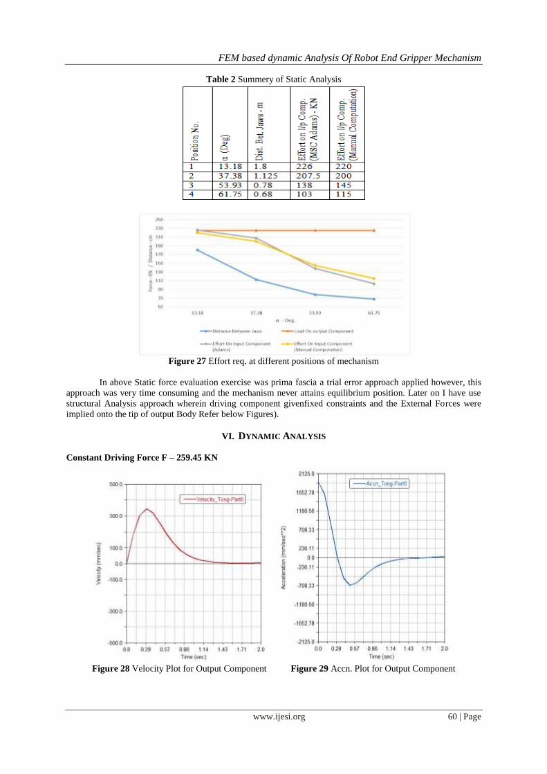
The robotic gripper is simulated for 225 KN Load. The MSC Adams results generated from simulation

of Robotic gripper shows that the effort required to hold the object is inversely proportional to angle ‘α’ and

directly proportional to distance between Jaws. Validation of static analysis carried out by the analytical manual

computation to determine the efforts required to hold the object firmly and both the results appears in precise

significance each other.

During later phase of analysis of dynamic effects along with software packages such as MSC Adams

and ANSYS Workbench 16.2 is used. To get the desired motion displacement of driven component that is

gripper jaws the driving component was applied with force of F = 259.5 KN. Itis observe that the mechanism

requires the force, which is about 150 KN to start the motion by overcoming the mass inertia of the several

component however; the entire mechanism keeps on oscillating because of unbalanced inertias. Then to

understand effect of sinusoidal force of magnitude of 1.4F applied to the driving component. Under this

condition, the mechanism oscillates and velocity and accelerations fluctuates a lot. This is because of sinusoidal

nature of force caused by simple harmonic motion. Similarly, the analysis with Sinusoidal Force Magnitude is

double 2 x 1.4 x F carried out to check the system response. We can conclude that the oscillations increase with

increase in magnitude of sinusoidal force.

In the final FEA phase, static study results of von Mises stresses and deformation with maximum

values of 305.27 MPa and of 3.65 mm. In this transient analysis, our area of interest was Part 5 Main Arm. The

transient analysis shows the variation in stresses and deformation at different instances.

After carrying out the present work, still work may extend to develop vibration analysis and

Optimization of Robotic Gripper.

REFERENCES [1]. Bai, G. (2016). Kinematic analysis and dimensional synthesis of a meso-gripper. ASME 2016 International Design Engineering

Technical Conferences 2016.

[2]. Birglen, L. (2017). A statistical review of industrial robotic grippers. ELSEVIER Robotics and Computer–Integrated

Manufacturing.

[3]. Campeau-Lecours, A. (2017). An articulated assistive robot for intuitive hands-on-payload manipulation. ELSEVIER Robotics and Computer–Integrated Manufacturing.

[4]. Causey, G. (2003). Guidelines for the design of robotic gripping systems . MCB UP Ltd / Emerald Group Publishing.

[5]. Chappell, P. (1999). Kinematic control of a three-fingered and fully adaptive end-effector using a Jacobian matrix. ELSEVIER Mechatronics.

[6]. Dalibor Petkovi, e. a. (2016). Analyzing of flexible gripper by computational intelligence approach. ELSEVIER Mechatronics.

[7]. FantonI, G. (2014). Method for supporting the selection of robot grippers. ELSEVIER Procedia CIRP. [8]. Giulio Rosati, e. a. (2017). Design & const. of a variable aperture gripper for flexible automated assembly.

[9]. Han, L. (2016). Design Simulation of a Handling Robot for Bagged Agricultural Materials. ELSEVIER IFAC-Papers Online.

FEM based dynamic Analysis Of Robot End Gripper Mechanism

www.ijesi.org 67 | Page

[10]. Hassana, A. (2016). Modeling and design optimization of a robot gripper mechanism. ELSEVIER Robotics and Computer–

Integrated Manufacturing(2001).

[11]. International Federation of Robotics (IFR). (2016). Executive Summary World Robotics 2016 Industrial Robots. Retrieved from https://ifr.org/: https://ifr.org/img/uploads/Executive_Summary_WR_Industrial_Robots_20161.pdf

[12]. Kurfess, T. R. (2005). ROBOTICS AND AUTOMATION HANDBOOK. Boca Raton London New York Washington D.C.: CRC

PRESS. [13]. Lee., J. (2003). Kinematic synthesis of Industrial Robot Gripper A Creative Design Approach. ELSEVIER Robotics and

Autonomous Systems (2003).

[14]. Melchiorri., C. (1997). Multiple whole-limb manipulation: An analysis in the force domain. ELSEVIER Robotics and Autonomous Systems.

[15]. Moghaddam, M. (2016). Parallelism of Pick-and-Place operations by multi-gripper robotic arms. ELSEVIER Robotics and

Computer–Integrated Manufacturing. [16]. Nguyen, C. C. (2003). Dynamic analysis of a 6 dof CKCM robot end-effector for dual-arm tele robot systems. ELSEVIER Robotics

and Autonomous Systems.

[17]. Rituparna Datta, S. P. (2015). Analysis and Design Optimization of a Robotic Gripper Using Multi-objective Genetic Algorithm. Analysis and Design Optimization of a Robotic Gripper Using Multi-objective Genetic Algorithm.

[18]. Robotics Breakthroughs From the Past Decade. (n.d.). Retrieved from Mashable: http://mashable.com/2013/10/23/robotics-

breakthroughs/#IbGvIv9uiaqX [19]. RobotShop Distribution Inc. (2008 ). http://www.robotshop.com/media/files/PDF/timeline. Retrieved from www.robotshop.com:

http://www.robotshop.com/media/files/PDF/timeline.pdf

Sachin Badadhe "Fem Based Dynamic Analysis Of Robot End Gripper Mechanism

"International Journal of Engineering Science Invention (IJESI), vol. 07, no. 11, 2018, pp 50-67


Recommended