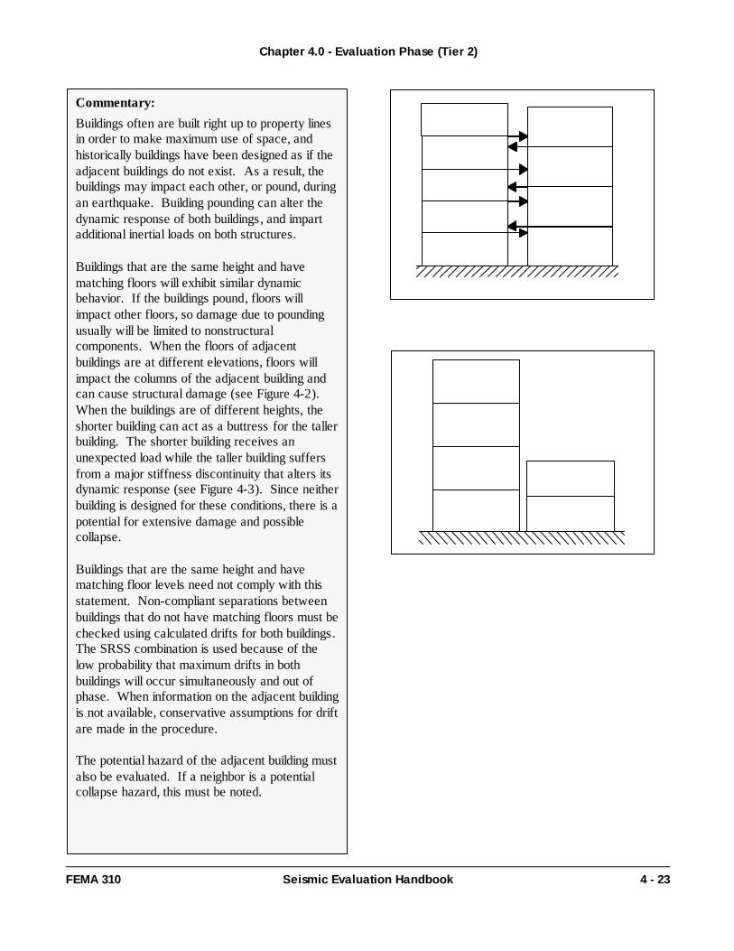
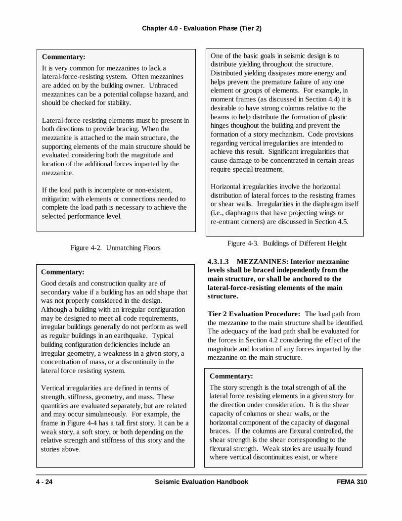
FEMA-310 Handbook for the Seismic Evaluation of Buildings, 1998 Introduction The American Society of Civil Engineers (ASCE) contracted with the Federal Emergency Management Agency (FEMA) to convert FEMA 178, NEHRP Handbook for the Seismic Evaluation of Existing Buildings into a prestandard. The development of the prestandard was the first step in turning FEMA 178 into an American National Standards Institute (ANSI) approved national consensus standard. The document was completed in January 1998 and is published as FEMA 310, Handbook for the Seismic Evaluation of Buildings--A Prestandard. Notice American Society of Civil Engineers (ASCE) has completed its effort to turn FEMA 310 into a national consensus-based standard. The document is now known as ASCE 31-02 and supercedes FEMA 310. Therefore, the document on this page is for information purposes only. For more information on obtaining a copy of ASCE 31-02, please contact ASCE at www.asce.org This report was prepared under a cooperative agreement between the Federal Emergency Management Agency and the American Society of Civil Engineers. Any opinions, findings, conclusions, or recommendations expressed in this publication do not necessarily reflect the views of FEMA or ASCE. Additionally, neither FEMA, ASCE, nor any of their employees make any warranty, expressed or implied, nor assumes any legal liability or responsibility for the accuracy, completeness, or usefulness of any information, product, or process included in this publication. Users of information from this publication assume all liability arising from such use. Due to electronic incompatibilities, the entire FEMA 310 electronic version is not available. Also, the format may not be exactly as shown in the published version. However, the content is the same as the published version.
Transcript
FEMA-310
Handbook for the Seismic Evaluation of Buildings, 1998
Introduction
The American Society of Civil Engineers (ASCE) contracted with the Federal Emergency Management Agency (FEMA) to convert FEMA 178, NEHRP Handbook for the Seismic Evaluation of Existing Buildings into a prestandard. The development of the prestandard was the first step in turning FEMA 178 into an American National Standards Institute (ANSI) approved national consensus standard. The document was completed in January 1998 and is published as FEMA 310, Handbook for the Seismic Evaluation of Buildings--A Prestandard.
Notice
American Society of Civil Engineers (ASCE) has completed its effort to turn FEMA 310 into a national consensus-based standard. The document is now known as ASCE 31-02 and supercedes FEMA 310. Therefore, the document on this page is for information purposes only. For more information on obtaining a copy of ASCE 31-02, please contact ASCE at www.asce.org
This report was prepared under a cooperative agreement between the Federal Emergency Management Agency and the American Society of Civil Engineers. Any opinions, findings, conclusions, or recommendations expressed in this publication do not necessarily reflect the views of FEMA or ASCE. Additionally, neither FEMA, ASCE, nor any of their employees make any warranty, expressed or implied, nor assumes any legal liability or responsibility for the accuracy, completeness, or usefulness of any information, product, or process included in this publication. Users of information from this publication assume all liability arising from such use.
Due to electronic incompatibilities, the entire FEMA 310 electronic version is not available. Also, the format may not be exactly as shown in the published version. However, the content is the same as the published version.
1.1 Scope
This Handbook provides a three-tiered process forseismic evaluation of existing buildings in any region ofseismicity. Buildings are evaluated to either the LifeSafety or Immediate Occupancy Performance Level.
Use of this Handbook and mitigation of deficienciesidentified using this Handbook are voluntary or asrequired by the authority having jurisdiction. Thedesign of mitigation measures is not addressed in thisHandbook.
This Handbook does not preclude a building from beingevaluated by other well-established procedures basedon rational methods of analysis in accordance withprinciples of mechanics and approved by the authorityhaving jurisdiction.
Chapter 1.0 - General Provisions
FEMA 310 Seismic Evaluation Handbook 1 - 1
1.0 General Provisions
Commentary:
This Handbook provides a process for seismicevaluation of existing buildings. A major portion isdedicated to instructing the evaluating designprofessional on how to determine if a building isadequately designed and constructed to resistseismic forces. All aspects of building performanceare considered and defined in terms of structural,nonstructural and foundation/geologic hazard issues.
Prior to using this Handbook, a rapid visualscreening of the building may be performed todetermine if an evaluation is needed using thefollowing document:
Rapid Visual Screening of Buildings forPotential Seismic Hazards: A Handbook(FEMA 154 and 155).
Mitigation strategies for rehabilitating buildingsfound to be deficient are not included in thisHandbook; additional resources should be consultedfor information regarding mitigation strategies.
Handbook Basis
This Handbook is based on the NEHRP Handbookfor Seismic Evaluation of Existing Buildings(FEMA 178). This Handbook was written to:
reflect advancements in technology, incorporate design professional experience,incorporate lessons learned during recentearthquakes, be nationally applicable, and provide evaluation techniques for varyinglevels of building performance.
Since the development and publication of FEMA178, numerous significant earthquakes haveoccurred: the 1985 Michoacan Earthquakes thataffected the Mexico City area, the 1989 LomaPrieta Earthquake in the San Francisco Bay Area,the 1994 Northridge Earthquake in the Los Angelesarea, and the 1995 Hyokogen-Nanbu Earthquake inthe Kobe area. While each earthquake validatedthe fundamental assumptions underlying theprocedures presented in FEMA 178, each alsooffered new insights into the potential weaknessesin certain systems that should be mitigated. (Itshould be noted that while the publication of FEMA178 occurred after the Mexico City and LomaPrieta Earthquakes, data and lessons learned fromthem were unable to be incorporated into thedocument prior to publication.)
Extent of Application
Model building codes typically exempt certainclasses of buildings from seismic requirementspertaining to new construction. This is most oftendone because the building is unoccupied or it is of astyle of construction that is naturally earthquakeresistant. It is reasonable to expect that theseclasses of buildings may be exempt from therequirements of this Handbook as well.
No buildings are automatically exempt from theevaluation provisions of this Handbook; exemptions
1.2 Basic
Chapter 1.0 - General Provisions
1 - 2 Seismic Evaluation Handbook FEMA 310
some cases a reduced level of performance hasbeen allowed to avoid damaging historic fabric.
The following resources may be useful whenevaluating historic structures:
Secretary of the Interior's Standards forthe Treatment of Historic Properties, andNational Park Service Catalog ofHistorical Preservation Publications.
Alternative Methods
Alternative documents that may be used to evaluateexisting buildings include:
Uniform Code for Building Conservation(UCBC, 1997), Los Angeles Division 91, Los Angeles Division 95, andSeismic Evaluation and Retrofit ofConcrete Buildings.
Some users have based the seismic evaluation ofbuildings on the provisions of new buildings. Whilethis may seem appropriate, it must be done with fullknowledge of the inherent assumptions. Codes fornew buildings contain three basic types ofrequirements including strength, stiffness, anddetailing. The strength and stiffness requirementsare easily transferred to existing buildings; thedetailing provisions are not. If thelateral-force-resisting elements of an existingbuilding do not have the proper details ofconstruction, the basic expectations of the otherstrength and stiffness provisions will not be met.Lateral-force-resisting elements that are notproperly detailed should be omitted during anevaluation using a code for new buildings.
ATC-14 offered the first technique for adjusting theevaluation for the lack of proper detailing by using athree-level acceptance criteria, FEMA 178 usedreduced R-factors to accomplish the same thing.FEMA 273 contains the most comprehensiveprocedure with its element-based approach. ThisHandbook follows the lead of FEMA 273 with anew style of analysis procedure tailored to the Tier1 and Tier 2 evaluation levels.
exemptions should be defined by public policy.However, based on the exemption contained in thecodes for new buildings, jurisdictions may exemptthe following classes of construction:
Detached one- and two-family dwellingslocated where the design short-periodspectral response acceleration parameter,SDS, is less than 0.4g.Detached one- and two-family wood framedwellings located where the designshort-period response accelerationparameter, SDS, is equal to or greater than0.4g that satisfy the light-frame constructionrequirements of the 1997 NEHRPRecommended Provisions for SeismicRegulations for New Buildings; and Agricultural storage structures that areintended only for incidental humanoccupancy.
Application to Historic Buildings
Although the principles for evaluating historicstructures are similar to those for other buildings,special conditions and considerations may exist ofwhich the design professional should be aware.
Historic structures often include archaic materials,systems, and details. It may be necessary to look athandbooks and building codes from the year ofconstruction to determine details and materialproperties.
Another unique aspect of historic building evaluationis the need to consider architectural elements orfinishes. Testing that damages the historiccharacter of the building generally is not acceptable.
In addition, an appropriate level of performance forhistoric structures needs to be chosen that isacceptable to the local jurisdiction. Some feel thathistoric buildings should meet the safety levels ofother buildings since they are a subset of thegeneral seismic safety needs. Others feel thathistoric structures, because of their value to society,should meet a higher level of performance. And insome cases a reduced level of performance has
Requirements
Prior to conducting the seismic evaluation, theevaluation requirements of Chapter 2 shall be met.
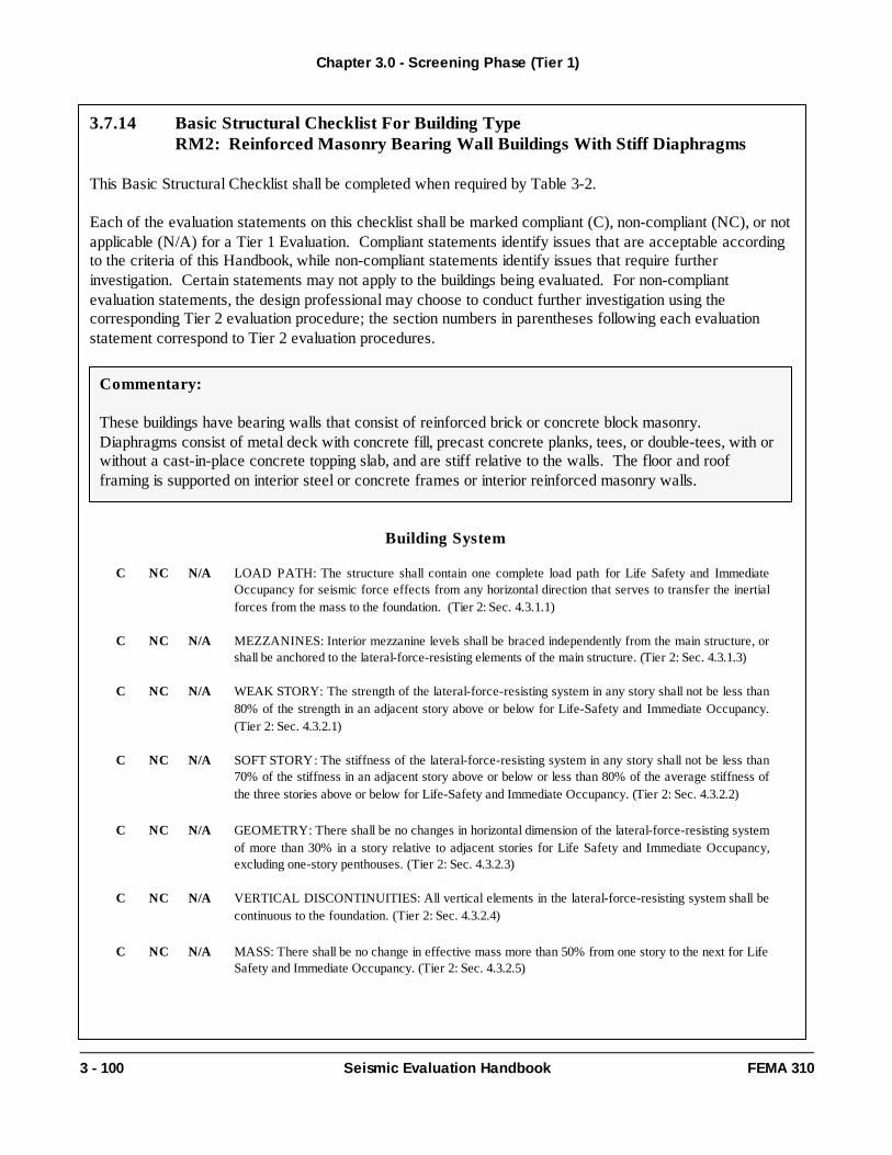
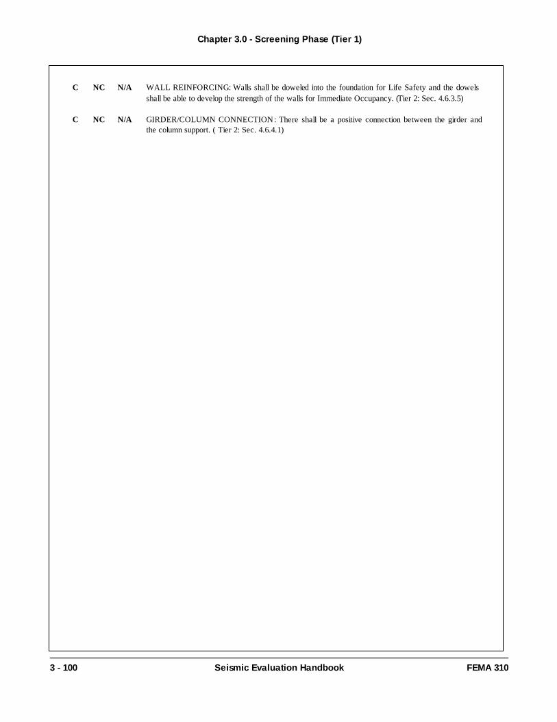
A Tier 1 evaluation shall be conducted for all buildingsin accordance with the requirements of Chapter 3.Checklists, as applicable, of compliant/non-compliantstatements related to structural, nonstructural andfoundation conditions, shall be selected and completedin accordance with the requirements of Section 3.3 fora Tier 1 Evaluation. Potential deficiencies shall besummarized upon completion of the Tier 1 evaluation.
Structural Tier 1 checklists are not provided forunreinforced masonry bearing wall buildings withflexible diaphragms. The structural evaluation ofunreinforced masonry bearing wall buildings withflexible diaphragms shall be completed using the Tier 2Special Procedure of Section 4.2.6; a Tier 1 Evaluationfor foundations and non-structural elements remainsapplicable for this type of building.
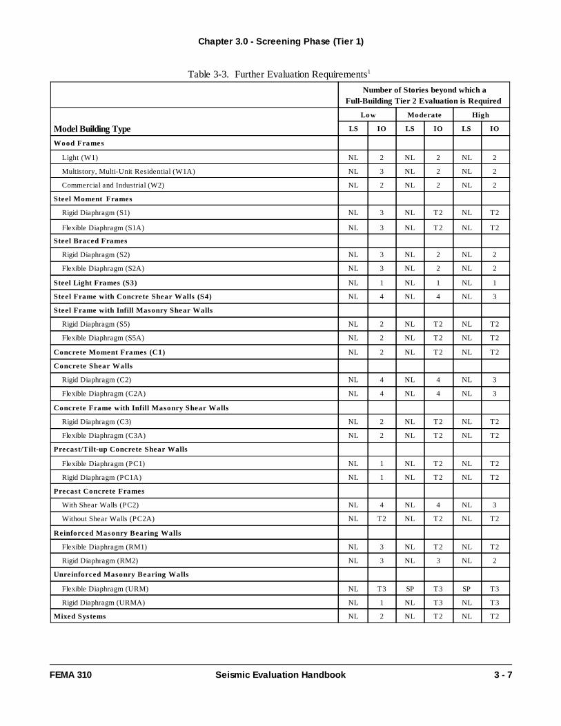
For those buildings identified in Section 3.4, aFull-Building Tier 2 Evaluation or a Tier 3 Evaluationshall be performed upon completion of the Tier 1Evaluation.
For those buildings not identified in Section 3.4 asrequiring a Full Building Tier 2 Evaluation or a Tier 3Evaluation, but for which potential deficiencies wereidentified in Tier 1, a Deficiency-Only Tier 2Evaluation may be performed. For a Deficiency-OnlyTier 2 Evaluation, only the procedures associated withnon-compliant checklist statements need be completed.Potential deficiencies shall be summarized uponcompletion of the Tier 2 Evaluation. Alternatively, thedesign professional may choose to end the investigationand report the deficiencies in accordance with Chapter1.
A Tier 3 evaluation shall be performed in accordancewith the requirements of Chapter 5 for buildingsidentified in Section 3.4 or when the designprofessional chooses to further evaluate buildings forwhich potential deficiencies were identified in Tier 1 orTier 2. Potential deficiencies shall be summarizedupon completion of the Tier 3 Evaluation.
After a seismic evaluation has been performed, a finalreport shall be prepared. As a minimum, the reportshall identify: the building and its character, the tier(s)of evaluation used, and the findings.
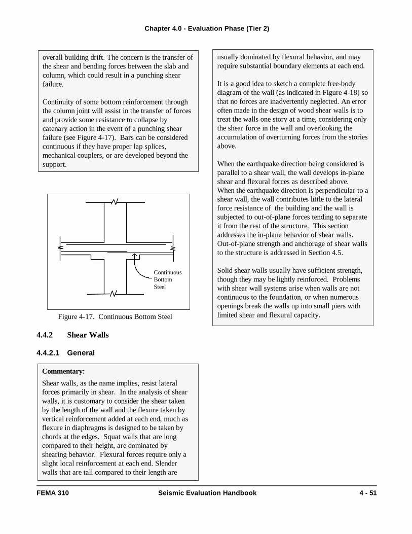
The three-tiered process for seismic evaluation ofbuildings is depicted in Figure 1-1.
Chapter 1.0 - General Provisions
FEMA 310 Seismic Evaluation Handbook 1 - 3
Commentary:
Prior to conducting the seismic evaluation based onthis Handbook, the design professional shouldunderstand the evaluation process and the basicrequirements specified in this section.
The evaluation process consists of the followingthree tiers, which are shown in Figure 1-1:Screening Phase (Tier 1), Evaluation Phase (Tier2), and Detailed Evaluation Phase (Tier 3). Asindicated in Figure 1-1, the design professional maychoose to (i) report deficiencies and screening
Mitigation Strategies
Potential seismic deficiencies in existing buildingsmay be identified using this Handbook. If theevaluation is voluntary, the owner may choose toaccept the risk of damage from future earthquakesrather than upgrade, or demolish the building. If theevaluation is required by a local ordinance for ahazard-reduction program, the owner may have tochoose between rehabilitation, demolition, or otheroptions.
The following documents may be useful indetermining appropriate rehabilitation or mitigationstrategies:
NEHRP Handbook of Techniques for theSeismic Rehabilitation of ExistingBuildings (FEMA 172), NEHRP Benefit-Cost Model for theSeismic Rehabilitation of Buildings(FEMA 227 and 228), NEHRP Typical Costs for SeismicRehabilitation of Existing Buildings(FEMA 156 and 157), and NEHRP Guidelines and Commentary forthe Seismic Rehabilitation of Buildings(FEMA 273 and 274).
Chapter 1.0 - General Provisions
1 - 4 Seismic Evaluation Handbook FEMA 310
recommend mitigation or (ii) conduct furtherevaluation, after any tier of the evaluation process.
The screening phase, Tier 1, consists of 3 sets ofchecklists that allow a rapid evaluation of thestructural, nonstructural and foundation/geologichazard elements of the building and site conditions.It shall be completed for all building evaluationsconducted in accordance with this Handbook. Thepurpose of a Tier 1 evaluation is to screen outbuildings that comply with the provisions of thisHandbook or quickly identify potential deficiencies.In some cases "Quick Checks" may be requiredduring a Tier 1 evaluation, however, the level ofanalysis necessary is minimal. If deficiencies areidentified for a building using the checklists, thedesign professional may proceed to Tier 2 andconduct a more detailed evaluation of the building orconclude the evaluation and state that potentialdeficiencies were identified. In some cases a Tier 2or Tier 3 evaluation may be required.
Based on the ABK research (ABK, 1984),unreinforced masonry buildings with flexiblediaphragms were shown to behave in a uniquemanner. Special analysis procedures provided inSection 4.2.6 were developed to predict thebehavior. Since this special procedure does not lenditself to the checklist format of Tier 1, no StructuralChecklists are provided. The design professionalmust perform the Tier 2 Special Procedure as thefirst step of the evaluation. The Special Procedureonly applies to the structural aspects of the building;Tier 1 Checklists provided for the nonstructuralelements and for the foundation and geologichazards issues still apply.
For Tier 2, a complete analysis of the building thataddresses all of the deficiencies identified in Tier 1shall be performed. Analysis in Tier 2 is limited tosimplified linear analysis methods. As in Tier 1,evaluation in Tier 2 is intended to identify buildingsnot requiring rehabilitation. If deficiencies areidentified during a Tier 2 evaluation, the designprofessional may choose to either conclude theevaluation and report the deficiencies or proceed toTier 3 and conduct a detailed seismic evaluation.
Available methods and references for conducting aTier 3 detailed evaluation are described in Chapter 5of this Handbook. Recent research has shown thatcertain types of complex structures can be shown tobe adequate using nonlinear analysis procedureseven though other common procedures do not.While these procedures are complex and expensiveto carry out, they often result in construction savingsequal to many times their cost. The use of Tier 3procedures must be limited to appropriate cases.
The final report serves to communicate the results tothe owner and record the process and assumptionsused to complete the evaluation. Each sectionshould be carefully written in a manner that isunderstandable to its intended audience. The extentof the final report may range from a letter to adetailed document. The final report should include atleast the following items:
1) Scope and Intent: a list of the tier(s)followed and level of investigationconducted;
2) Site and Building Data:General building description (number ofstories and dimensions),
Structural system description (framing,lateral load resisting system, floor androof diaphragm construction, basement,and foundation system),
Nonstructural element description (nonstructural elements that couldinteract with the structure and affectseismic performance)Building type,
Performance Level,Region of Seismicity,Soil Type,Building Occupancy, andHistoric Significance;
3) List of Assumptions: material properties,site soil conditions;
4) Findings: list of deficiencies;5) Recommendations: mitigation schemes or
further evaluation;6) Appendix: references, preliminary
calculations.
Chapter 1.0 - General Provisions
FEMA 310 Seismic Evaluation Handbook 1 - 5
1) Collect Data and Visit Site2) Determine Region of Seismicity3) Determine Level of Performance
Evaluation Requirements
Tier 1: Screening Phase
Tier 2: Evaluation Phase
Benchmark Building? OR1) Complete the Structural Checklist(s).2) Complete the Foundation Checklist.3) Complete the Nonstructural Checklist(s).
Deficiencies?
EVALUATE Building using one of the following procedures: 1) Linear Static Procedure 2) Linear Dynamic Procedure 3) Special Procedure
ANALYSIS
Tier 3: Detailed Evaluation Phase
Comprehensive Investigation (Nonlinear Analysis)
Final Evaluation and Report
no
Ch. 2
Ch. 3
Ch. 4
Ch. 5
Ch. 1
Understand the Evaluation Process
General Provisions
Ch. 1
Mitigate
QUICK CHECKS
FurtherEval?
y e s
y e s
no
Deficiencies?no FurtherEval?
y e s
y e s
no
Deficiencies?no y e sBuilding Complies
Building does NOT
Comply
FULL BUILDING or DEFICIENCY-ONLY EVALUATION
Figure 1-1. Evaluation Process
1.3 Definitions
ACTION: Forces or moments that causedisplacements and deformations.
ASPECT RATIO: Ratio of full height to length forshear walls; ratio of span to depth for horizontaldiaphragms.
BASIC NONSTRUCTURAL CHECKLIST: Setof evaluation statements that shall be completed aspart of the Tier 1 Evaluation. Each statementrepresents a potential nonstructural deficiency basedon performance in past earthquakes.
BASIC STRUCTURAL CHECKLIST: Sets ofevaluation statements that shall be completed as partof the Tier 1 Evaluation. Each statement represents apotential structural deficiency based on performance inpast earthquakes.
BENCHMARK BUILDING: A building designedand constructed or evaluated to a specific performancelevel using an acceptable code or standard listed inTable 3-1.
BUILDING TYPE: A building classification definedin Section 2.6, that groups buildings with commonlateral-force-resisting systems and performancecharacteristics in past earthquakes.
CAPACITY: The permissible strength ordeformation for a component action.
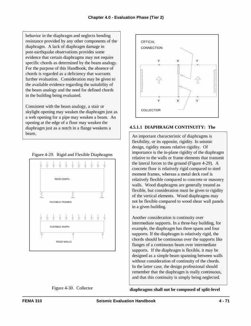
COLLECTOR: A member that transfers lateralforces from the diaphragm of the structure to verticalelements of the lateral-force resisting system.
CROSS WALL: A wood-framed wall sheathed withlumber, structural panels, or gypsum wallboard.
DEFICIENCY-ONLY TIER 2 EVALUATION:An evaluation, beyond the Tier 1 Evaluation, thatinvestigates only the non-compliant checklist evaluationstatements.
DESIGN EARTHQUAKE: See MaximumConsidered Earthquake.
DIAPHRAGM: A horizontal structural system thatserves to interconnect the building and acts to transmitlateral forces to the vertical resisting elements.
DIAPHRAGM EDGE: The intersection of thehorizontal diaphragm and a shear wall.
DISPLACEMENT-CONTROLLED ACTION:An action that has an associated deformation that isallowed to exceed the yield value of the element beingevaluated. The extent of permissible deformationbeyond yield is based on component modificationfactors (m-factors).
EXPECTED STRENGTH: The actual strength of amaterial, not the specified minimum or nominalstrength. For purposes of an evaluation using thisHandbook, the expected strength shall be taken equalto the nominal strength multiplied by 1.25.Alternatively, actual statistically based test data maybe used.
FLEXIBLE DIAPHRAGM: A diaphragm wherethe maximum lateral deformation along its length ismore than twice the average inter-story drift.
FORCE-CONTROLLED ACTION: An actionthat has an associated deformation that is not allowedto exceed the yield value of the element beingevaluated. The action is not directly related to thepseudo seismic forces used in the evaluation, rather itis based on the maximum action that can be deliveredto the element by the yielding structural system.
Chapter 1.0 - General Provisions
1 - 6 Seismic Evaluation Handbook FEMA 310
Judgment by the Design Professional
While this Handbook provides very prescriptivedirection for the evaluation of existing buildings, it isnot to be taken as the only direction. This Handbookprovides direction for common details, deficienciesand behavior observed in past earthquakes that arefound in common building types. However, everystructure is unique and may contain features anddetails not covered by this Handbook. It is importantthat the design professional use judgment whenapplying the provisions of this Handbook. The designprofessional should always be looking for uncommondetails and behavior about the structure not coveredby this Handbook that may have the potential fordamage or collapse.
FULL-BUILDING TIER 2 EVALUATION: Anevaluation beyond a Tier 1 Evaluation that involves acomplete analysis of the entire lateral-force-resistingsystem of the building using the Tier 2 analysisprocedures defined in Section 4.2. While specialattention should be given to the potential deficienciesidentified in the Tier 1 evaluation, all lateral forceresisting elements must be evaluated. This evaluationis required when triggered by Table 3-3.
GEOLOGIC SITE HAZARDS ANDFOUNDATIONS CHECKLIST: Set of evaluationstatements that shall be completed as part of the Tier 1Evaluation. Each statement represents a potentialfoundation or site deficiency based on the performanceof buildings in past earthquakes.
IMMEDIATE OCCUPANCY PERFORMANCELEVEL: Building performance that includes verylimited damage to both structural and nonstructuralcomponents during the design earthquake. The basicvertical and lateral-force-resisting systems retainnearly all of their pre-earthquake strength andstiffness. The level of risk for life-threatening injury asa result of damage is very low. Although some minorrepairs may be necessary, the building is fully habitableafter a design earthquake, and the needed repairs maybe completed while the building is occupied.
LATERAL FORCE RESISTING SYSTEM: Thecollection of frames, shear walls, bearing walls, bracedframes and interconnecting horizontal diaphragms thatprovides earthquake resistance to a building.
LIFE SAFETY PERFORMANCE LEVEL:Building performance that includes significant damageto both structural and nonstructural components duringa design earthquake, though at least some marginagainst either partial or total structural collapseremains. Injuries may occur, but the level of risk forlife-threatening injury and entrapment is low.
LINEAR DYNAMIC PROCEDURE (LDP): ATier 2 response spectrum based modal analysisprocedure shall be used for buildings taller than 100feet, buildings with vertical or geometric irregularities,and buildings where the distribution of the lateralforces departs from that assumed for the Linear StaticProcedure.
LINEAR STATIC PROCEDURE (LSP): A Tier 2lateral force analysis procedure where the pseudolateral force is equal to the force required to imposethe expected actual deformation of the structure in itsyielded state when subjected to the design earthquakemotions. It shall be used for buildings for which theLinear Dynamic or the Special Procedure is notrequired.
MAXIMUM CONSIDERED EARTHQUAKE:An earthquake with a 2% probability of exceedance in50 years with deterministic-based maximum valuesnear known fault sources.
MOMENT-RESISTING FRAME (MRF): Aframe capable of resisting horizontal forces becausethe members (beams and columns) and joints arecapable of resisting forces primarily by flexure.
PRIMARY COMPONENT: A part of thelateral-force-resisting system capable of resistingseismic forces.
PSEUDO LATERAL FORCE (V): The calculatedlateral force used for the Tier 1 Quick Checks and forthe Tier 2 Linear Static Procedure. The pseudo lateralforce represents the force required, in a linear analysis,to impose the expected actual deformation of thestructure in its yielded state when subjected to thedesign earthquake motions. It does not represent anactual lateral force that the building must resist in traditional code design.
QUICK CHECK: Analysis procedure used in Tier 1Evaluations to determine if the lateral-force-resistingsystem has sufficient strength and/or stiffness.
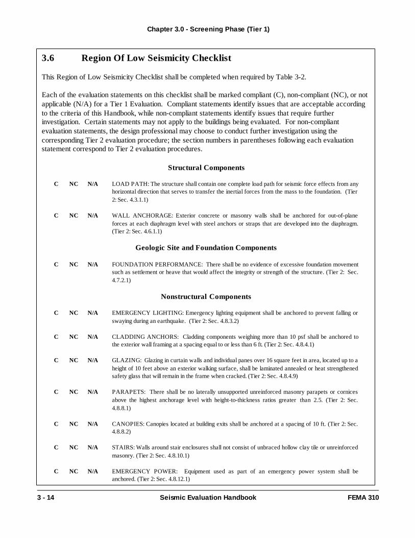
REGION OF LOW SEISMICITY CHECKLIST:Set of evaluation statements that shall be completed aspart of the Tier 1 Evaluation for buildings in regions oflow seismicity being evaluated to the Life SafetyPerformance Level.
Chapter 1.0 - General Provisions
FEMA 310 Seismic Evaluation Handbook 1 - 7
REGION OF SEISMICITY: An area with similarexpected earthquake hazard. For this Handbook, allregions are categorized as low, moderate, or high,based on mapped acceleration values and siteamplification factors as defined in Section 2.5.
RIGID DIAPHRAGM: A diaphragm where themaximum lateral deformation is less than half theaverage inter-story drift associated with the story.
SECONDARY COMPONENT: An element that iscapable of resisting gravity loads, but is not able toresist seismic forces it attracts, though is not needed toachieve the designated performance level.
SITE CLASS: Groups of soil conditions that affectthe site seismicity in a common manner. The soil typesused are defined in Section 3.5.2.3.1; designated as A,B, C, D, E, or F.
SPECIAL PROCEDURE: Analysis procedure,used for unreinforced masonry bearing wall buildingswith flexible diaphragms, that properly characterizesthe diaphragm motion, strength and damping.
SPECIAL PROCEDURE TIER 2EVALUATION: An evaluation procedurespecifically written for unreinforced masonry bearingwall buildings with flexible diaphragms using thespecial procedure.
STIFF DIAPHRAGM: A diaphragm that is notclassified as either flexible or rigid.
STORY SHEAR FORCE: Portion of the pseudolateral force carried by each story of the building.
SUPPLEMENTAL NONSTRUCTURALCHECKLIST: Set of nonstructural evaluationstatements that shall be completed as part of the Tier 1Evaluation for buildings in regions of moderate or highseismicity being evaluated to the ImmediateOccupancy Performance Level.
SUPPLEMENTAL STRUCTURALCHECKLIST: Set of evaluation statements thatshall be completed as part of the Tier 1 Evaluation forbuildings in regions of moderate seismicity beingevaluated to the Immediate Occupancy PerformanceLevel, and for buildings in regions of high seismicity.
TIER 1 EVALUATION: Completion of checklistsof evaluation statements that identifies potentialdeficiencies in a building based on performance in pastearthquakes.
TIER 2 EVALUATION: The specific evaluation ofpotential deficiencies to determine if they representactual deficiencies that may require mitigation.Depending on the building type, this evaluation may bea Full-Building Tier 2 Evaluation, Deficiency-Only Tier2 Evaluation, or a Special Procedure Tier 2 Evaluation.
TIER 3 EVALUATION: A comprehensive buildingevaluation implicitly or explicitly recognizing nonlinearresponse.
1.4 Notation
ap Component amplification factor,
Abr Average cross-sectional area of thediagonal brace,
Ac Summation of the cross-sectional area ofall columns in the story underconsideration,
An Area of net mortared/grouted section (in2),
Aw Summation of the horizontalcross-sectional area of all shear walls inthe direction of loading,
Ax Amplification factor to account foraccidental torsion,
C Modification factor to relate expectedmaximum inelastic displacementscalculated for linear elastic response,
C Compliant,
Cp Horizontal force factor,
Ct Modification factor, based on earthquakerecords, used to adjust the building periodto account for the characteristics of thebuilding system,
Cvx Vertical distribution factor, based on storyweights and heights, that defines atriangular loading pattern,
Chapter 1.0 - General Provisions
1 - 8 Seismic Evaluation Handbook FEMA 310
D In-plane width dimension of masonry (in.)or depth of diaphragm (ft.),
DCR Demand-capacity ratio,
Dp Relative displacement,
DR, Dr Drift ratio,
E Modulus of Elasticity;
Fa Site Coefficient defined in Table 3-6,
fbr Average axial stress in diagonal bracingelements,
Fi Lateral force applied at floor level i,
Fpx Total diaphragm force at level x,
Fv Site Coefficient defined in Table 3-5,
Fwx Force applied to a wall at level x (lb.),
Fx Total story force at level x,
Fy Yield Stress,
h Story height,
hi,hx Height (ft.) from the base to floor level i orx,
hn Height (in feet) above the base to the rooflevel,
H Least clear height of opening on eitherside of pier (in.),
I Moment of Inertia,
IO Immediate Occupancy PerformanceLevel,
j number of story level under consideration,
J Force-delivery reduction factor,
k Exponent related to the building period,
kb Stiffness of a representative beam (I/L);
kc Stiffness of a representative column (I/h);
L Length;
Lbr Average length of the diagonal brace,
LS Life-Safety Performance Level,
m Component modification factor,
Mg Moment in girder (k-ft),
n, N number of stories above ground,
N/A Not Applicable,
Nbr Number of diagonal braces in tension andcompression if the braces are designed forcompression; Number of diagonal bracesin tension if the braces are designed fortension only,
nc Total number of columns,
nf Total number of frames,
NC Non-Compliant,
NL No Limit,
PCE Expected gravity compressive forceapplied to a wall or pier component stress,
PD Superimposed dead load at the top of thepier under consideration (lb.),
SD1 Design spectral response accelerationparameter at a one-second period,
SS Short-period spectral responseacceleration parameter,
S1 Spectral response acceleration parameterat a one-second period,
t Thickness of wall (in.)
Chapter 1.0 - General Provisions
FEMA 310 Seismic Evaluation Handbook 1 - 9
T Fundamental period of vibration of thebuilding,
T1 Tier 1 Evaluation,
T2 Tier 2 Evaluation,
T3 Tier 3 Evaluation,
vavg Average shear stress,
vme Expected masonry shear strength (psi),
vu Unit shear strength for a diaphragm(lb./ft.),
v te Average bed-joint shear strength (psi), notto exceed 100 psi,
V Pseudo lateral force,
Va Shear strength of an unreinforced masonrypier (lb.),
Vc Column shear force,
Vca Total shear capacity of cross walls in thedirection of analysis immediately above thediaphragm level being investigated (lb.),
Vcb Total shear capacity of cross walls in thedirection of analysis immediately below thediaphragm level being investigated (lb.),
Vd Diaphragm shear (lb.),
Vj Story shear force,
Vp Shear force on an unreinforced masonrywall pier (lb.),
Vr Pier rocking shear capacity of anunreinforced masonry wall or wall pier(lb.),
Vwx Total shear force resisted by a shear wallat the level under consideration (lb.),
wi, wx Portion of the total building weightassigned to floor level i or x,
W Total seismic weight,
Wd Total dead load tributary to a diaphragm(lb.),
Wj Total seismic weight of all stories abovelevel j,
Wp Component operating weight,
Ww Total dead load of an unreinforcedmasonry wall above the level underconsideration or above an open front of abuilding,
Wwx Dead load of an unreinforced masonrywall assigned to level x halfway above andbelow the level under consideration (lb.),
x Height in structure of highest point ofattachment of component,
X,Y Height of lower support attachment atlevel x or y as measured from grade,
∆d Diaphragm displacement,
∆w In-plane wall displacement,
δavg the maximum dispalcement at any point ofdiaphragm at level x,
δmax the algebraic average of displacements atthe extreme points of the diaphragm atlevel x,
δxA,δyA Deflection at building level x or y ofbuilding A,
δxB Deflection at building level x of building B,
ρ'' Volumetric ratio of horizontal confinementreinforcement in a joint.
Chapter 1.0 - General Provisions
1 - 10 Seismic Evaluation Handbook FEMA 310
1.5 References
ACI, 1995, Building Code Requirements forReinforced Concrete, ACI 318-95, AmericanConcrete Institute, Detroit, Michigan.
AISC, 1993, Load and Resistance Factor DesignSpecification for Structural Steel Buildings,American Institute of Steel Construction, Inc.,Chicago, Illinois.
ASCE, 1995, ASCE 7-95, Minimum Design Loadsfor Buildings and Other Structures, AmericanSociety of Civil Engineers, New York, New York.
BOCA, 1993, National Building Code, BuildingOfficials and Code Administrators International,Country Club Hill, Illinois.
CBSC, 1995, California Building Code (Title 24),California Building Standards Commission,Sacramento, California.
FEMA, 1998, Seismic Map Package, FederalEmergency Management Agency, Washington D.C.
ICBO, 1994, Uniform Building Code, InternationalConference of Building Officials, Whittier, California.
MSS, 1993, Pipe Hangers and Supports: Materials,Design and Manufacture, SP-58, ManufacturersStandardization Society of the Valve and FittingIndustry, Vienna, Virginia.
NFPA, 1996, Standard for the Installation ofSprinkler Systems, NFPA-13, National FireProtection Association, Quincy, Massachusetts.
SBCC, 1993, Standard Building Code, SouthernBuilding Code Congress International, Birmingham,
Alabama.
Chapter 1.0 - General Provisions
FEMA 310 Seismic Evaluation Handbook 1 - 11
Commentary:
ABK, 1984, Methodology for Mitigation ofSeismic Hazards in Existing UnreinforcedMasonry Buildings: The Methodology, TopicalReport 08, National Science Foundation,Washington, D.C.
BSSC, 1992a, NEHRP Handbook for the SeismicEvaluation of Existing Buildings, developed bythe Building Seismic Safety Council for the FederalEmergency Management Agency (Report No.FEMA 178), Washington, D.C.
BSSC, 1992b, NEHRP Handbook of Techniquesfor the Seismic Rehabilitation of ExistingBuildings, developed by the Building SeismicSafety Council for the Federal EmergencyManagement Agency (Report No. FEMA 172),Washington, D.C.
BSSC, 1995, NEHRP Recommended Provisionsfor Seismic Regulations for New Buildings, 1994Edition, Part 1: Provisions and Part 2:Commentary, developed by the Building SeismicSafety Council for the Federal EmergencyManagement Agency (Report No. FEMA 222Aand 223A), Washington, D.C.
BSSC, 1997, NEHRP Guidelines for the SeismicRehabilitation of Buildings, developed by theBuildings Seismic Safety Council for the FederalEmergency Management Agency (Report No.FEMA 273), Washington, D.C.
BSSC, 1997, NEHRP Commentary for the SeismicRehabilitation of Buildings, developed by theBuildings Seismic Safety Council for the FederalEmergency Management Agency (Report No.FEMA 274), Washington, D.C.
SAC, 1995, Interim Guidelines: Evaluation,Repair, Modification and Design of SteelMoment Frames, developed by the SAC JointVenture (Report No. SAC-95-02) for the FederalEmergency Management Agency (Report No.FEMA 267), Washington, D.C.
SAC, 1997, Interim Guidelines Advisory No. 1:Supplement to FEMA 267, developed by the SACJoint Venture (Report No. SAC-96-03) for theFederal Emergency Management Agency (ReportNo. FEMA 267A), Washington, D.C.
SEAOC, 1996, Recommended Lateral ForceRequirements and Commentary, Sixth Edition,Structural Engineers Association of California,Sacramento, California.
Chapter 1.0 - General Provisions
1 - 12 Seismic Evaluation Handbook FEMA 310
This Page IntentionallyLeft Blank
2.1 General
Prior to conducting a seismic evaluation, the evaluationrequirements of this Chapter shall be met.
2.2 Level of Investigation Required
Prior to conducting a Tier 1 Evaluation, all availabledocuments shall be collected and reviewed. Acomplete examination of all available documentspertaining to the design and construction of the buildingshall be conducted. If construction documents areavailable, the examination shall include verification thatthe building was constructed in accordance with thedocuments. All alterations and deviations shall benoted. The information collected shall be sufficient todefine the level of performance desired in accordancewith Section 2.4, the region of seismicity in accordancewith Section 2.5, and the building type in accordancewith Section 2.6. In addition, the level of investigationshall be sufficient to complete the Tier 1 Checklists.Destructive examination shall be conducted as requiredto complete the Checklists for buildings beingevaluated to the Immediate Occupancy PerformanceLevel; judgment shall be used regarding the need fordestructive evaluation for buildings being evaluated tothe Life-Safety Performance Level. Non-destructiveexamination of connections and conditions, shall beperformed for all Tier 1 Evaluations. Default valuesmay be used for material properties for a Tier 1Evaluation.
In addition to the information required for a Tier 1Evaluation, sufficient information shall be collected fora Tier 2 Evaluation to complete the required Tier 2Procedures. Destructive examination shall beconducted as required to complete the Procedures forbuildings being evaluated to the Immediate OccupancyPerformance Level and for buildings in regions of highseismicity as defined in Table 2-1. Non-destructiveexamination of connections and conditions shall beperformed for all Tier 2 Evaluations. While materialtesting is not required for a Tier 2 Evaluation, default
values for material properties shall not be used.Material property data shall be obtained from buildingcodes from the year of construction of the buildingbeing evaluated, from as-built plans, or from physicaltests.
Exception: Unreinforced masonry bearing wallbuildings with flexible diaphragms using the Tier 2Special Procedure of Section 4.2.6 shall havedestructive tests conducted to determine the averagebed-joint shear strength, vte, and the strength of theanchors.
Detailed information about the building is required for aTier 3 Evaluation. If no documents are available, anas-built set of drawings shall be created indicating theexisting lateral-force-resisting system. Non-destructive and destructive examination and testingshall be conducted for a Tier 3 Evaluation to establish:
the expected strength of all materials thatparticipate in the lateral-force-resisting systemof the building; deterioration shall be taken intoaccount;the composition and configuration of allprimary components and conditions in thelateral-force-resisting system.
Chapter 2.0 - Evaluation Requirements
FEMA 310 Seismic Evaluation Handbook 2 - 1
2.0 Evaluation Requirements
Commentary:
Building evaluation involves many substantialdifficulties. One is the matter of uncovering thestructure since plans and calculations often are notavailable. In many buildings the structure isconcealed by architectural finishes, and the designprofessional will have to get into attics, crawlspaces, and plenums to investigate. Some intrusivetesting may be necessary to determine materialquality and allowable stresses. If reinforcing plansare available, some exposure of criticalreinforcement may be necessary to verifyconformance with the plans. The extent ofinvestigation required depends on the level of
2.3 Site Visit
A site visit shall be conducted by the evaluating designprofessional to verify existing data or collect additionaldata, determine the general condition of the building,and verify or assess the site conditions.
Chapter 2.0 - Evaluation Requirements
2 - 2 Seismic Evaluation Handbook FEMA 310
evaluation because the conservatism inherent inboth the Tier 1 and Tier 2 analysis covers the lackof detailed information in most cases. Theevaluating deisgn professional is encouraged tobalance the investigation with the sophistication ofthe evaluation technique.
The design professional in responsible charge shouldbe consulted if possible. In addition, the evaluatingdesign professional may find it helpful to do someresearch on historical building systems, consult oldhandbooks and building codes, and perhaps consultwith older engineers who have knowledge of earlystructural work in the community or region.
The evaluation should be based on facts, as opposedto assumptions, to the greatest extent possible.
One of the more important factors in any evaluationis the material properties and strengths. For a Tier 1Evaluation, the following default values may beassumed: f'c of 3000 psi for concrete, Fy of 40 ksifor reinforcing steel, Fy of 36 ksi for structural steel,f'm of 1500 psi for masonry. For a Tier 2 Evaluation,the material strengths can be determined by existingdocumentation or material testing. For a Tier 3Evaluation, material testing is required to verify theexisting documentation or establish the strengths ifexisting documentation is not available.
Prior to evaluating a building using this handbook,the design professional should:
Look for an existing geotechnical report onsite soil conditions;Establish site and soil parameters;Assemble building design data includingcontract drawings, specifications, andcalculations;Look for other data such as assessments ofthe building performance during past earthquakes; andSelect and review the appropriate sets ofevaluation statements included in Chapter 3.
Testing of Masonry
Different types of masonry require different tests todetermine the shear capacity. The designprofessional should use the following as a generalguide for selecting the correct test method:
Multi-wythe masonry laid with headersshould use the in-place shear push test;For modern masonry, the design professionalshould consider using a core tested asprescribed in ASTM C 496-90 to determinethe tensile-splitting stress. Thetensile-splitting stress is the same as thehorizontal shear stress. The mortar jointsshould be at 45° to the load. This should bemodified for axial stress by Mohr'sprocedures;Another method is to use a square prismextracted from the wall that is tested asprescribed in ASTM E 519-74 to determinethe tensile-splitting stress. The method ofrelating the test to tensile-splitting in ASTME 519-74 requires verification. The effect ofaxial loading on the tensile-splitting stressmust be added for the expected horizontalshear stress;Use a prism extracted from the wall todetermine f'm. Then use f'm in empiricalformulas to determine the expected shearstrength;Trace the source of the masonry units forthe unit compressive strength. Then use theunit compressive strength with the mortarclass on the available construction.documents to determine f'm.
Chapter 2.0 - Evaluation Requirements
FEMA 310 Seismic Evaluation Handbook 2 - 3
Commentary:
Relevant building data that should be determinedthrough a site visit includes:
General building description - number of stories,year(s) of construction, and dimensions.Structural system description - framing,lateral-force-resisting system(s), floor and roofdiaphragm construction, basement, andfoundation system.Nonstructural element description -nonstructural elements that could interact withthe structure and affect seismic performance.Building type(s) - Categorize the building as oneor more of the Common Building Types, ifpossible.
Performance Level - Note the performancelevel required in the evaluation. Region of Seismicity - Identify the seismicity ofthe site to be used for the evaluation.Soil type - Note the soil type.Building Occupancy - The occupancy of thebuilding should be noted. Historic Significance - Identify any historicelements in the building. Any impacts or areasof the building affected by the evaluation shouldbe noted.
A first assessment of the evaluation statements mayindicate a need for more information about thebuilding. The design professional may need tore-visit the site to do the following:
1. Verify existing data; 2. Develop other required data;3. Verify the vertical and lateral-force-
resisting systems;4. Check the condition of the building;5. Look for special conditions and anomalies;6. Address the evaluation statements again
while in the field; and7. Perform material tests, as necessary.
Commentary:
FEMA 178 addressed only the Life SafetyPerformance Level for buildings. This Handbookaddresses both the Life Safety and ImmediateOccupancy Performance Levels.
The seismic analysis and design of buildings hastraditionally focused on one performance level;reducing the risk to life loss in the largest expectedearthquake. Building codes for new buildings andthe wide variety of evaluation guidelines developedin the last 30 years have based their provisions onthe historic performance of buildings and thedeficiencies that caused life safety concerns todevelop. Beginning with the damage to hospitals inthe 1971 San Fernando earthquake, there has beena growing desire to design and construct certain“essential facilities” that that are neededimmediately after an earthquake. In addition, therehas been a growing recognition that new buildingsshould have some measure of damaged resistancebuilt in while existing buildings need to be held onlyto a minimum safety standard. During this time, anew style of design guidelines began appearing thatpromised a variety of performance levels. At oneextreme, the ABK Methodology was developed tobetter understand when URM buildings needed tobe strengthened to achieve a minimum level ofsafety. At the other extreme, the California BuildingCode for Hospital Design and Construction set the
2.4 Level of Performance
A desired level of performance shall be defined priorto conducting a seismic evaluation using thisHandbook. The level of performance shall bedetermined by the design professional and by theauthority having jurisdiction. The following twoperformance levels for both structural andnonstructural components are defined in Section 1.3 ofthis handbook: Life Safety (LS) and ImmediateOccupancy (IO). For both performance levels, theseismic demand is based on Maximum ConsideredEarthquake (MCE) spectral response accelerationvalues. Buildings complying with the criteria of thisHandbook shall be deemed to meet the specifiedperformance level.
Chapter 2.0 - Evaluation Requirements
2 - 4 Seismic Evaluation Handbook FEMA 310
Construction set the criteria for buildings that needto remain operational.
The extensive and expensive, non-life threateningdamage that occurred in the NorthridgeEarthquake brought these various performancelevels to the point of formalization. PerformanceBased Engineering was rigorously described by theStructural Engineers Association of California intheir Vision 2000 document. At the same time, theEarthquake Engineering Research Centerpublished a research and development plan for thedevelopment of Performance Based EngineeringGuidelines and Standards. The first formalapplication in published guidelines occurred inFEMA 273, where the range of possibleperformance levels and hazard levels werecombined to define specific performance objectivesto be used to rehabilitate buildings.
This Handbook defines and uses performancelevels in a manner consistent with FEMA 273. The Life Safety and Immediate OccupancyPerformance Levels are the same as defined inFEMA 273. The hazard level used is the third in aseries of four levels defined in FEMA 273. Thelevel chosen is consistent with the hazardtraditionally used for seismic analysis and similar tothat used in FEMA 178. For other performancelevels and/or hazard levels, the design professionalshould perform a Tier 3 analysis.
The process for defining the appropriate level ofperformance is the responsibility of the designprofessional or the authority having jurisdiction.Considerations in choosing an appropriate level ofperformance should include achieving basic safety,a cost-benefit analysis, the building occupancytype, economic constraints, etc.
In general, buildings classified as essential facilitiesshould be evaluated to the Immediate OccupancyPerformance Level. The 1997 NEHRPRecommended Provisions for SeismicRegulations for New Buildings categorizes thefollowing buildings as essential facilities "...requiredfor post-earthquake recovery":
Fire or rescue and police stations,
Hospitals or other medical facilities havingsurgery or emergency treatment facilities, Emergency preparedness centers includingthe equipment therein, Power generating stations or other utilitiesrequired as emergency back-up facilitiesfor other facilities listed here, Emergency vehicle garages, Communication centers, and Buildings containing sufficient quantities oftoxic or explosive substances deemed to bedangerous to the public if released.
2.5 Region of Seismicity
The region of seismicity of the building shall be definedas low, moderate, or high in accordance with Table
2-1. Regions of seismicity are defined in terms ofmapped response acceleration values and siteamplification factors.
Table 2-1. Regions of Seismicity DefinitionsRegion ofSeismicity1
SDS SD1
Low < 0.167g < 0.067g
Moderate < 0.500g> 0.167g
< 0.200g> 0.067g
High > 0.500g > 0.200g
1The highest region of seismicity defined by SDS orSD1 shall govern.
where: SDS = 23FaSs
= design short-period spectral response
Chapter 2.0 - Evaluation Requirements
FEMA 310 Seismic Evaluation Handbook 2 - 5
Commentary:
Fundamental to the Tier 1 analysis of buildings is thegrouping of buildings into sets that have similarbehavioral characteristics. These groups of“building types” were first defined in ATC-14 andhave been used in most of the FEMA guidelinedocuments since. During the development ofFEMA 273, it was determined that a number ofadditional types of buildings were needed to coverall common styles of construction. These were fullydeveloped and presented in that document. Theadded building types included a Northridge-styleapartment building, and a number of variations ondiaphragm type for the basic building systems. Thenew types are included as subtypes to the originalfifteen, so there remains fifteen model buildingtypes.
The common building types are defined in Table2-2. Because most structures are unique in somefashion, judgment should be used when selecting thebuilding type, with the focus on thelateral-force-resisting system and elements.
Separate checklists for each of the CommonBuilding Types are included in this Handbook aswell as General Structural Checklists for buildingsthat may not be classified as one of the CommonBuilding Types. Procedures for using the GeneralChecklists are provided in Section 3.3.
experience at the Marina District in the Loma PrietaEarthquake is ample evidence of its credibility.
Commentary:
The successful performance of buildings in areas ofhigh seismicity depends on a combination ofstrength, ductility (manifested in the details ofconstruction) and the presence of a fullyinterconnected, balanced, and completelateral-force-resisting system. As thesefundamentals are applied in regions of lowerseismicity, the need for strength and ductilityreduces substantially and, in fact, strength cansubstitute for a lack of ductility. Very brittlelateral-force-resisting systems can be excellentperformers as long as they are never pushedbeyond their elastic strength.
ATC-14, the first generation version of FEMA 178recognized this fact and defined separate provisionsfor regions of low and high seismicity. Based inpart on work sponsored by the Nation Center forEarthquake Engineering Research (NCEER, 1987)FEMA 178 eliminated the separate provisions andelected to permit the lateral force calculations todetermine when there was sufficient strength tomake up for a lack of detailing and ductility.
The collective experience of the engineers usingFEMA 178 is that the requirements too oftenrequire calculations for deficiencies that are never aproblem because of the low lateral forces. ThisHandbook took this experience and has developthree separate Tier 1 procedures for the threefundamental regions of seismicity. The regions aredefined in terms of the expected spectral responsefor the site under consideration. Thus the criteriafor an area bepends both on the expected MCEaccelerations and on the site adjustment factors.This will cause area in the transition zone betweenregions to have sub-areas that are in one regionimmediately adjacient to a sub-area in anotherregion. This is an intentional result and the
Chapter 2.0 - Evaluation Requirements
2 - 6 Seismic Evaluation Handbook FEMA 310
Table 2-2. Common Building Types
Building Type 1 : Wood Light Frames
W1 These buildings are single or multiple family dwellings of one or more stories in height. Building loadsare light and the framing spans are short. Floor and roof framing consists of closely spaced wood joistsor rafters on wood studs. The first floor framing is supported directly on the foundation, or is raised upon cripple studs and post and beam supports. The foundation consists of spread footings constructedof concrete, concrete masonry block, or brick masonry in older construction. Chimneys, when present,consist of solid brick masonry, masonry veneer, or wood frame with internal metal flues. Lateral forcesare resisted by wood frame diaphragms and shear walls. Floor and roof diaphragms consist of straightor diagonal wood sheathing, tongue and groove planks, or plywood. Shear walls consist of straight ordiagonal wood sheathing, plank siding, plywood, stucco, gypsum board, particle board, or fiberboard.Interior partitions are sheathed with plaster or gypsum board.
W1A These buildings are multi-story, multi-unit residences similar in construction to W1 buildings, but withopen front garages at the first story. The first story consists of wood floor framing on wood stud wallsand steel pipe columns, or a concrete slab on concrete or concrete masonry block walls.
Building Type 2: Wood Frames, Commercial and Industrial
W2 These buildings are commercial or industrial buildings with a floor area of 5,000 square feet or more.Building loads are heavier than light frame construction, and framing spans are long. There are few, ifany, interior walls. The floor and roof framing consists of wood or steel trusses, glulam or steel beams,and wood posts or steel columns. Lateral forces are resisted by wood diaphragms and exterior studwalls sheathed with plywood, stucco, plaster, straight or diagonal wood sheathing, or braced with rodbracing. Large openings for storefronts and garages, when present, are framed by post-and-beamframing. Lateral force resistance around openings is provided by steel rigid frames or diagonal bracing.
Building Type 3 : Steel Moment Frame s
S1 These buildings consist of a frame assembly of steel beams and steel columns. Floor and roof framingconsists of cast-in-place concrete slabs or metal deck with concrete fill supported on steel beams, openweb joists or steel trusses. Lateral forces are resisted by steel moment frames that develop theirstiffness through rigid or semi-rigid beam-column connections. When all connections are momentresisting connections, the entire frame participates in lateral force resistance. When only selectedconnections are moment resisting connections, resistance is provided along discrete frame lines.Columns are oriented so that each principal direction of the building has columns resisting forces instrong axis bending. Diaphragms consist of concrete or metal deck with concrete fill and are stiffrelative to the frames. When the exterior of the structure is concealed, walls consist of metal panelcurtain walls, glazing, brick masonry, or precast concrete panels. When the interior of the structure isfinished, frames are concealed by ceilings, partition walls and architectural column furring. Foundations consist of concrete spread footings or deep pile foundations.
S1A These buildings are similar to S1 buildings, except that diaphragms consist of wood framing oruntopped metal deck, and are flexible relative to the frames.
Chapter 2.0 - Evaluation Requirements
FEMA 310 Seismic Evaluation Handbook 2 - 7
Table 2-2. Common Building Types (cont'd)
Building Type 4 : Steel Braced Frame s
S2 These buildings consist of a frame assembly of steel beams and steel columns. Floor and roof framingconsists of cast-in-place concrete slabs or metal deck with concrete fill supported on steel beams, openweb joists or steel trusses. Lateral forces are resisted by tension and compression forces in diagonalsteel members. When diagonal brace connections are concentric to beam column joints, all memberstresses are primarily axial. When diagonal brace connections are eccentric to the joints, members aresubjected to bending and axial stresses. Diaphragms consist of concrete or metal deck with concrete filland are stiff relative to the frames. When the exterior of the structure is concealed, walls consist ofmetal panel curtain walls, glazing, brick masonry, or precast concrete panels. When the interior of thestructure is finished, frames are concealed by ceilings, partition walls and architectural furring.Foundations consist of concrete spread footings or deep pile foundations.
S2A These buildings are similar to S2 buildings, except that diaphragms consist of wood framing oruntopped metal deck, and are flexible relative to the frames.
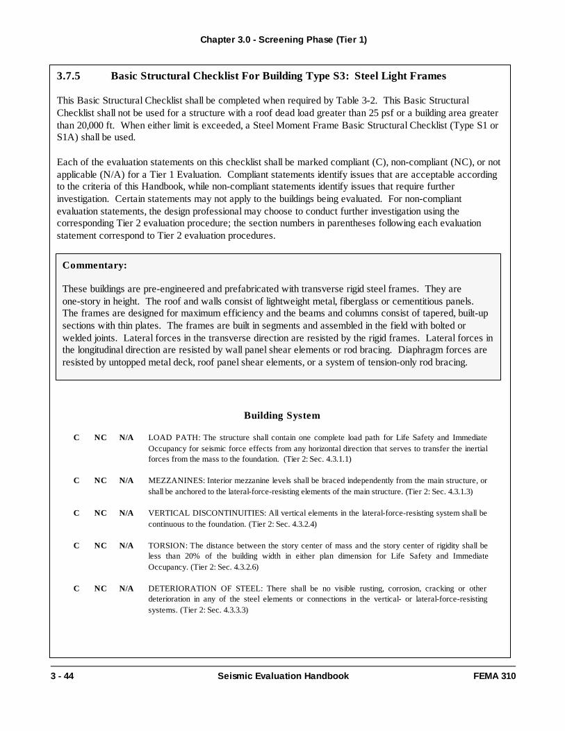
Building Type 5: Steel Light Frame s
S3 These buildings are pre-engineered and prefabricated with transverse rigid steel frames. They areone-story in height. The roof and walls consist of lightweight metal, fiberglass or cementitious panels.The frames are designed for maximum efficiency and the beams and columns consist of tapered, built-upsections with thin plates. The frames are built in segments and assembled in the field with bolted orwelded joints. Lateral forces in the transverse direction are resisted by the rigid frames. Lateral forces inthe longitudinal direction are resisted by wall panel shear elements or rod bracing. Diaphragm forces areresisted by untopped metal deck, roof panel shear elements, or a system of tension-only rod bracing.
Building Type 6: Steel Frames with Concrete Shear Walls
S4 These buildings consist of a frame assembly of steel beams and steel columns. The floors and roofconsist of cast-in-place concrete slabs or metal deck with or without concrete fill. Framing consists ofsteel beams, open web joists or steel trusses. Lateral forces are resisted by cast-in-place concrete shearwalls. These walls are bearing walls when the steel frame does not provide a complete vertical supportsystem. In older construction the steel frame is designed for vertical loads only. In modern dualsystems, the steel moment frames are designed to work together with the concrete shear walls inproportion to their relative rigidity. In the case of a dual system, the walls shall be evaluated under thisbuilding type and the frames shall be evaluated under S1 or S1A, Steel Moment Frames. Diaphragmsconsist of concrete or metal deck with or without concrete fill. The steel frame may provide a secondarylateral-force-resisting system depending on the stiffness of the frame and the moment capacity of thebeam-column connections.
acceleration parameter;
Chapter 2.0 - Evaluation Requirements
2 - 8 Seismic Evaluation Handbook FEMA 310
Table 2-2. Common Building Types (cont'd)
Building Type 7 : Steel Frames with Infill Masonry Shear Walls
S5 This is an older type of building construction that consists of a frame assembly of steel beams and steelcolumns. The floors and roof consist of cast-in-place concrete slabs or metal deck with concrete fill.Framing consists of steel beams, open web joists or steel trusses. Walls consist of infill panelsconstructed of solid clay brick, concrete block, or hollow clay tile masonry. Infill walls may completelyencase the frame members, and present a smooth masonry exterior with no indication of the frame. Theseismic performance of this type of construction depends on the interaction between the frame and infillpanels. The combined behavior is more like a shear wall structure than a frame structure Solidly infilledmasonry panels form diagonal compression struts between the intersections of the frame members. Ifthe walls are offset from the frame and do not fully engage the frame members, the diagonalcompression struts will not develop. The strength of the infill panel is limited by the shear capacity ofthe masonry bed joint or the compression capacity of the strut. The post-cracking strength isdetermined by an analysis of a moment frame that is partially restrained by the cracked infill. Thediaphragms consist of concrete floors and are stiff relative to the walls.
S5A These buildings are similar to S5 buildings, except that diaphragms consist of wood sheathing oruntopped metal deck, or have large aspect ratios and are flexible relative to the walls.
Building Type 8: Concrete Moment Frame s
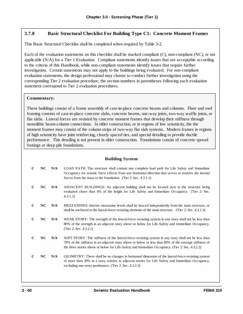
C1 These buildings consist of a frame assembly of cast-in-place concrete beams and columns. Floor androof framing consists of cast-in-place concrete slabs, concrete beams, one-way joists, two-way wafflejoists, or flat slabs. Lateral forces are resisted by concrete moment frames that develop their stiffnessthrough monolithic beam-column connections. In older construction, or in regions of low seismicity,the moment frames may consist of the column strips of two-way flat slab systems. Modern frames inregions of high seismicity have joint reinforcing, closely spaced ties, and special detailing to provideductile performance. This detailing is not present in older construction. Foundations consist ofconcrete spread footings or deep pile foundations.
Building Type 9 : Concrete Shear Wall Buildings
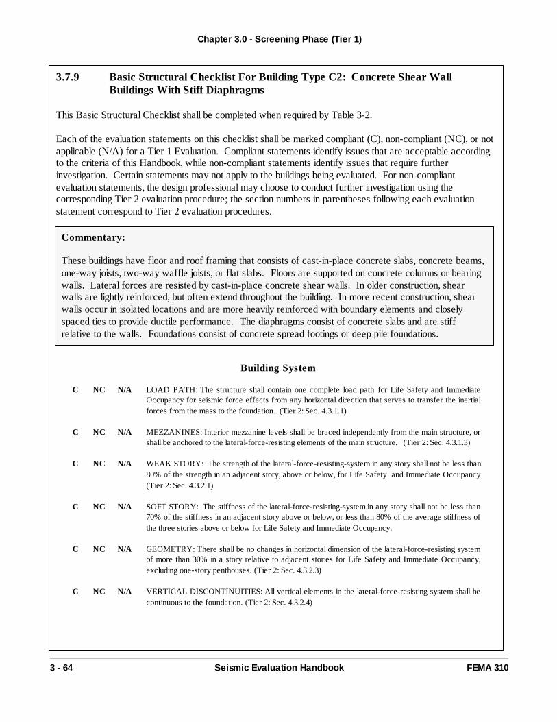
C2 These buildings have floor and roof framing that consists of cast-in-place concrete slabs, concretebeams, one-way joists, two-way waffle joists, or flat slabs. Floors are supported on concrete columnsor bearing walls. Lateral forces are resisted by cast-in-place concrete shear walls. In olderconstruction, shear walls are lightly reinforced, but often extend throughout the building. In morerecent construction, shear walls occur in isolated locations and are more heavily reinforced withboundary elements and closely spaced ties to provide ductile performance. The diaphragms consist ofconcrete slabs and are stiff relative to the walls. Foundations consist of concrete spread footings ordeep pile foundations.
C2A These buildings are similar to C2 buildings, except that diaphragms consist of wood sheathing, or havelarge aspect ratios, and are flexible relative to the walls.
Chapter 2.0 - Evaluation Requirements
FEMA 310 Seismic Evaluation Handbook 2 - 9
Table 2-2. Common Building Types (cont'd)
Building Type 10: Concrete Frames with Infill Masonry Shear Walls
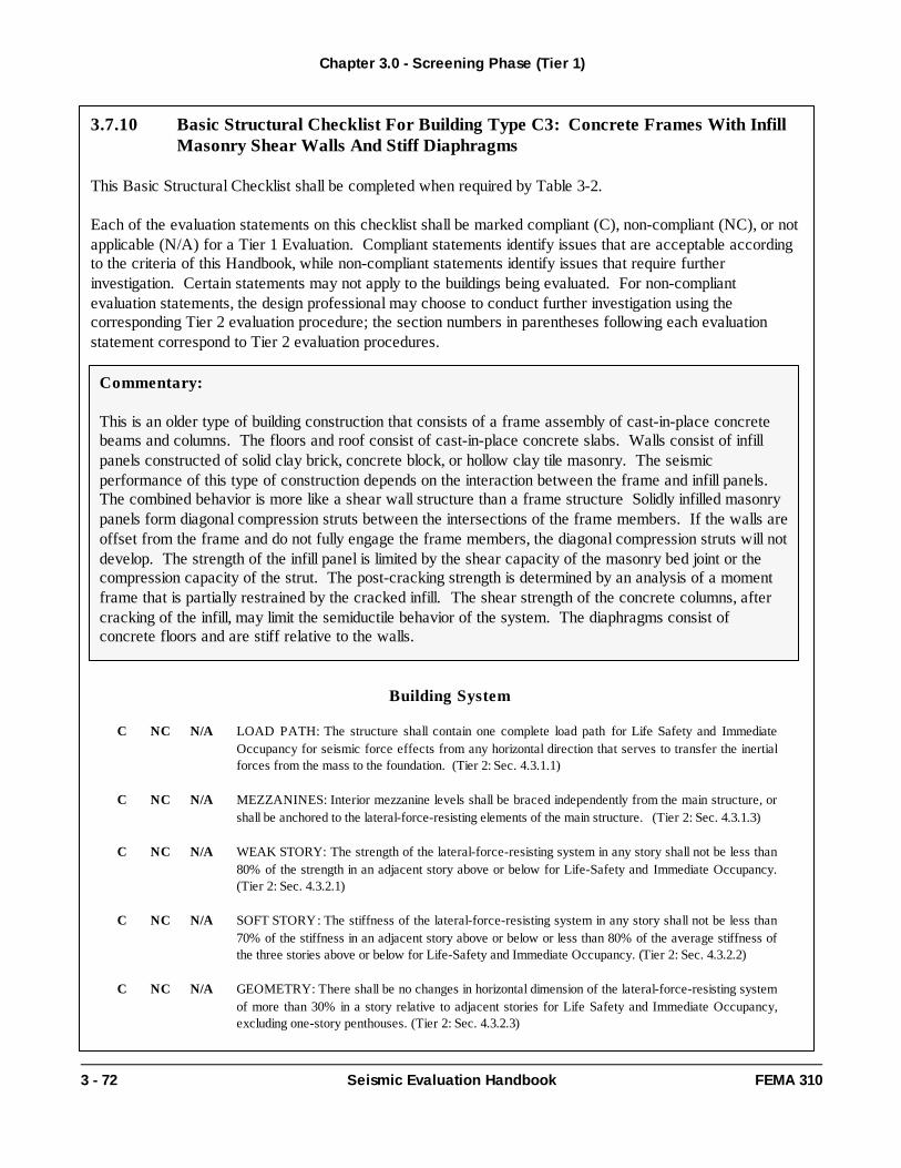
C3 This is an older type of building construction that consists of a frame assembly of cast-in-placeconcrete beams and columns. The floors and roof consist of cast-in-place concrete slabs. Wallsconsist of infill panels constructed of solid clay brick, concrete block, or hollow clay tile masonry. Theseismic performance of this type of construction depends on the interaction between the frame andinfill panels. The combined behavior is more like a shear wall structure than a frame structure Solidlyinfilled masonry panels form diagonal compression struts between the intersections of the framemembers. If the walls are offset from the frame and do not fully engage the frame members, thediagonal compression struts will not develop. The strength of the infill panel is limited by the shearcapacity of the masonry bed joint or the compression capacity of the strut. The post-cracking strengthis determined by an analysis of a moment frame that is partially restrained by the cracked infill. Theshear strength of the concrete columns, after cracking of the infill, may limit the semiductile behavior ofthe system. The diaphragms consist of concrete floors and are stiff relative to the walls.
C3A These buildings are similar to C3 buildings, except that diaphragms consists of wood sheathing, orhave large aspect ratios, and are flexible relative to the walls.
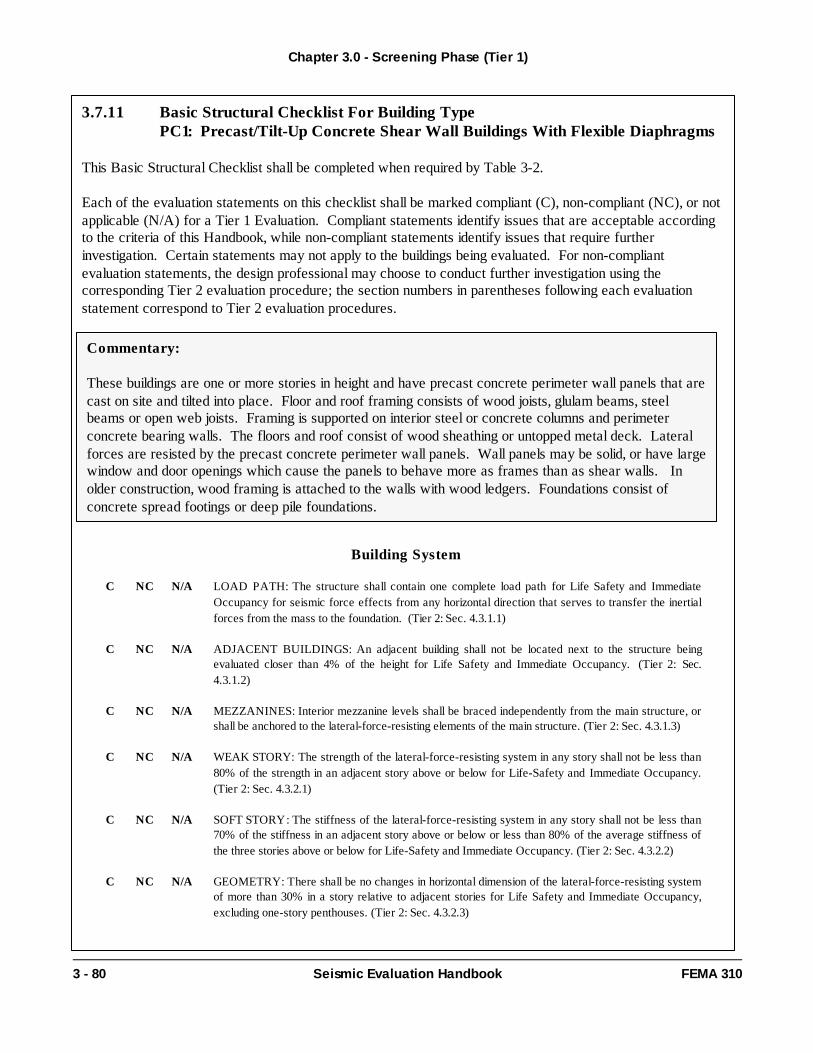
Building Type 11 : Precast/Tilt-up Concrete Shear Wall Buildings
PC1 These buildings are one or more stories in height and have precast concrete perimeter wall panels thatare cast on site and tilted into place. Floor and roof framing consists of wood joists, glulam beams,steel beams or open web joists. Framing is supported on interior steel columns and perimeter concretebearing walls. The floors and roof consist of wood sheathing or untopped metal deck. Lateral forcesare resisted by the precast concrete perimeter wall panels. Wall panels may be solid, or have largewindow and door openings which cause the panels to behave more as frames than as shear walls. Inolder construction, wood framing is attached to the walls with wood ledgers. Foundations consist ofconcrete spread footings or deep pile foundations.
PC1A These buildings are similar to PC1 buildings, except that diaphragms consist of precast elements,cast-in-place concrete, or metal deck with concrete fill, and are stiff relative to the walls.
Building Type 12 : Precast Concrete Frame s
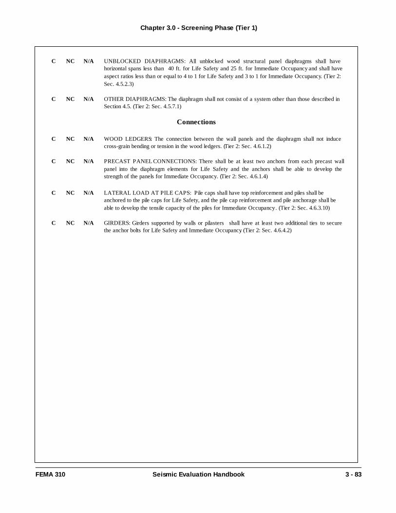
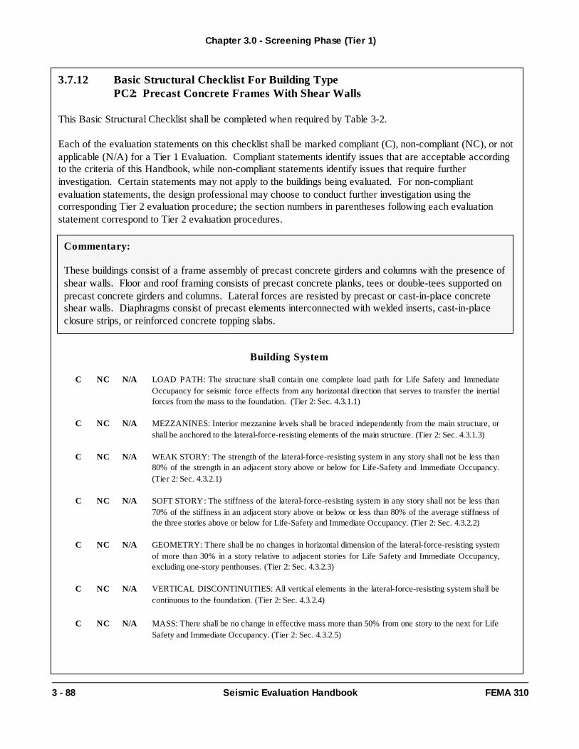
PC2 These buildings consist of a frame assembly of precast concrete girders and columns with the presenceof shear walls. Floor and roof framing consists of precast concrete planks, tees or double-teessupported on precast concrete girders and columns. Lateral forces are resisted by precast orcast-in-place concrete shear walls. Diaphragms consist of precast elements interconnected withwelded inserts, cast-in-place closure strips, or reinforced concrete topping slabs.
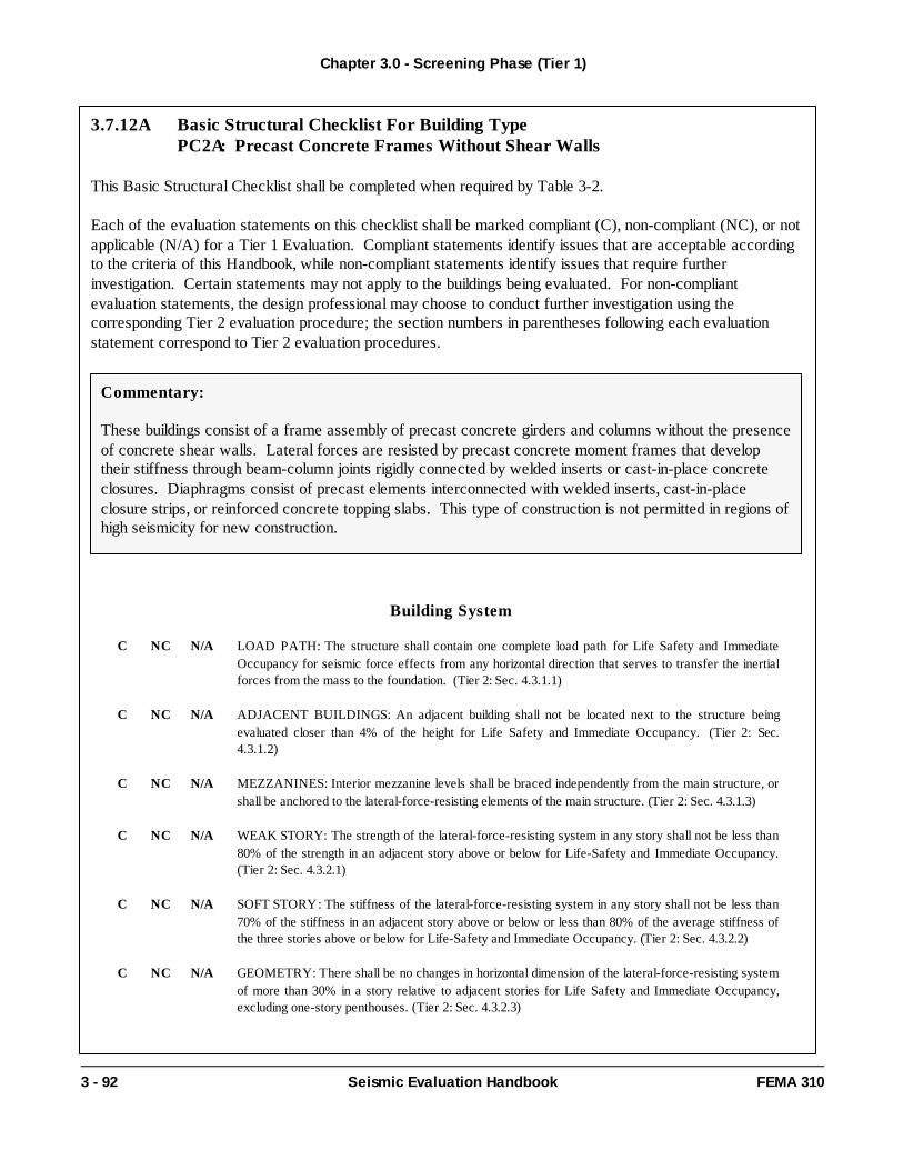
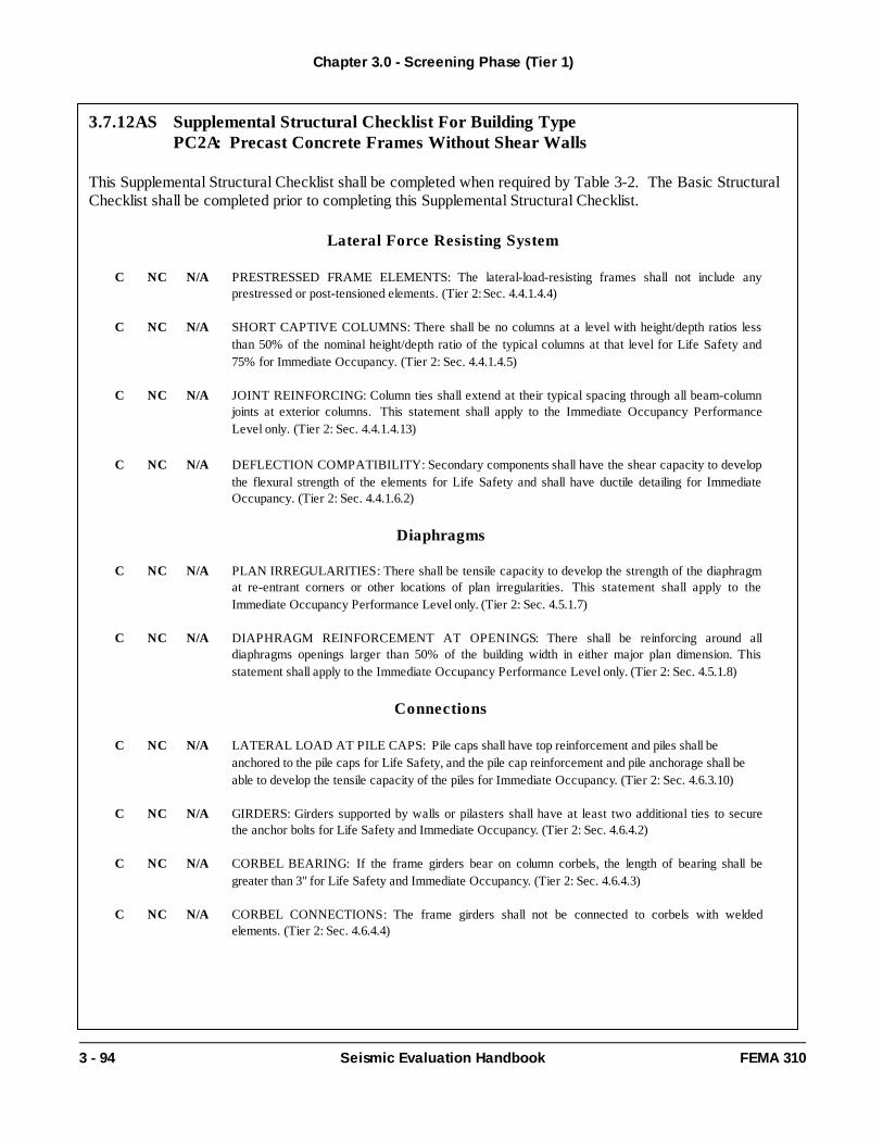
PC2A These buildings are similar to PC2 buildings, except that concrete shear walls are not present. Lateralforces are resisted by precast concrete moment frames that develop their stiffness throughbeam-column joints rigidly connected by welded inserts or cast-in-place concrete closures.Diaphragms consist of precast elements interconnected with welded inserts, cast-in-place closurestrips, or reinforced concrete topping slabs. This type of construction is not permitted in regions ofhigh seismicity for new construction.
Chapter 2.0 - Evaluation Requirements
2 - 10 Seismic Evaluation Handbook FEMA 310
Table 2-2. Common Building Types (cont'd)
Building Type 13: Reinforced Masonry Bearing Wall Buildings with Flexible Diaphragms
RM1 These buildings have bearing walls that consist of reinforced brick or concrete block masonry. Woodfloor and roof framing consists of wood joists, glulam beams and wood posts or small steel columns.Steel floor and roof framing consists of steel beams or open web joists, steel girders and steel columns.Lateral forces are resisted by the reinforced brick or concrete block masonry shear walls. Diaphragmsconsist of straight or diagonal wood sheathing, plywood, or untopped metal deck, and are flexiblerelative to the walls. Foundations consist of brick or concrete spread footings.
Building Type 14: Reinforced Masonry Bearing Wall Buildings with Stiff Diaphragms
RM2 These buildings are similar to RM1 buildings, except the diaphragms consist of metal deck withconcrete fill, precast concrete planks, tees, or double-tees, with or without a cast-in-place concretetopping slab, and are stiff relative to the walls. The floor and roof framing is supported on interior steelor concrete frames or interior reinforced masonry walls.
Building Type 15 : Unreinforced Masonry Bearing Wall Buildings
URM These buildings have perimeter bearing walls that consist of unreinforced clay brick masonry. Interiorbearing walls, when present, also consist of unreinforced clay brick masonry. In older constructionfloor and roof framing consists of straight or diagonal lumber sheathing supported by wood joists, onposts and timbers. In more recent construction floors consist of structural panel or plywood sheathingrather than lumber sheathing. The diaphragms are flexible relative to the walls. When they exist, tiesbetween the walls and diaphragms consist of bent steel plates or government anchors embedded in themortar joints and attached to framing. Foundations consist of brick or concrete spread footings.
URMA These buildings are similar to URM buildings, except that the diaphragms are stiff relative to theunreinforced masonry walls and interior framing. In older construction or large, multistory buildings,diaphragms consist of cast-in-place concrete. In regions of low seismicity, more recent constructionconsists of metal deck and concrete fill supported on steel framing.
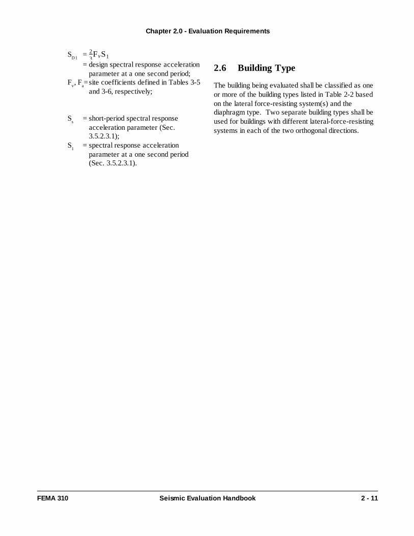
SD1 = 23FvS1
= design spectral response accelerationparameter at a one second period;
Fv , Fa= site coefficients defined in Tables 3-5and 3-6, respectively;
Ss = short-period spectral responseacceleration parameter (Sec.3.5.2.3.1);
S1 = spectral response accelerationparameter at a one second period(Sec. 3.5.2.3.1).
2.6 Building Type
The building being evaluated shall be classified as oneor more of the building types listed in Table 2-2 basedon the lateral force-resisting system(s) and thediaphragm type. Two separate building types shall beused for buildings with different lateral-force-resistingsystems in each of the two orthogonal directions.
Chapter 2.0 - Evaluation Requirements
FEMA 310 Seismic Evaluation Handbook 2 - 11
Chapter 2.0 - Evaluation Requirements
2 - 12 Seismic Evaluation Handbook FEMA 310
Chapter 2.0 - Evaluation Requirements
FEMA 310 Seismic Evaluation Handbook 2 - 13
3.1 General
A Tier 1 Evaluation shall be conducted for all buildingsafter the evaluation requirements of Chapter 2 havebeen completed. Tier 1 of the evaluation process isshown schematically in Figure 3-1.
Initially, the design professional shall determine whetherthe building meets the benchmark building criteria ofSection 3.2. If the building meets the benchmarkbuilding criteria, it shall be deemed to meet thestructural requirements of this Handbook for thespecified level of performance; a Tier 1 Evaluation forfoundations and nonstructural elements remainsapplicable.
If the building is not a benchmark building, the designprofessional shall select and complete the appropriatechecklists in accordance with Section 3.3.
Structural checklists are not used for unreinforcedmasonry bearing wall buildings with flexiblediaphragms. The structural evaluation of this type ofbuilding shall be completed using the Tier 2 SpecialProcedure of Section 4.2.6; a Tier 1 Evaluation forfoundations and nonstructural elements remainsapplicable for this type of building.
A list of deficiencies identified by evaluation statementsfor which the building was found to be non-compliantshall be compiled upon completion of the Tier 1Checklists.
Further evaluation requirements shall be determined inaccordance with Section 3.4 once the checklists havebeen completed.
3.2 Benchmark Buildings
A structural seismic evaluation using this Handbookneed not be performed for buildings designed andconstructed or evaluated in accordance with thebenchmark documents listed in Table 3-1; an evaluationfor foundations and nonstructural elements remainsapplicable. Table 3-1 identifies documents whoseseismic design, construction or evaluation provisions areacceptable for certain building types so that furtherevaluation is not required. If the seismicity of a regionhas changed since the benchmark dates listed in Table3-1, a building must have been designed andconstructed or evaluated in accordance with the currentseismicity of the region to be compliant with thissection. The design professional shall document in thefinal report the evidence used to determine that thebuilding is designed and constructed or evaluated inaccordance with the documents listed in Table 3-1 andcurrent seismicity of the region.
The applicable level of performance is indicated inTable 3-1 for each document as a superscript.
Chapter 3.0 - Screening Phase (Tier 1)
FEMA 310 Seismic Evaluation Handbook 3 - 1
3.0 Screening Phase (Tier 1)
professional with the building, its potentialdeficiencies and its potential behavior.
A Tier 1 Evaluation is required for all buildings sothat potential deficiencies may be quickly identified.Further evaluation using a Tier 2 or Tier 3 Evaluationwill then focus, as a minimum, on the potentialdeficiencies identified in Tier 1.
Commentary:
The purpose of the screening phase of theevaluation process is to identify quickly buildings thatcomply with the provisions of this handbook. A Tier1 Evaluation also familiarizes the design professional
Commentary:
While benchmark buildings need not proceed withfurther evaluation, it should be noted that they arenot simply exempt from the criteria of thisHandbook. The design professional must clearlydemonstrate the building is compliant with the
Chapter 3.0 - Screening Phase (Tier 1)
3 - 2 Seismic Evaluation Handbook FEMA 310
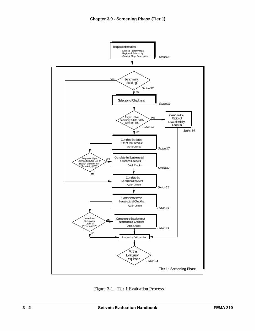
Figure 3-1. Tier 1 Evaluation Process
Tier 1: Screening Phase
Required Information:Level of PerformanceRegion of Seismici tyGeneral Bldg. Descript ion
Unreinforced Masonry (Type URMA) * * * * * *1Building Type refers to one of the Common Building Types defined in Table 2-2.2Buildings on hillside sites shall not be considered Benchmark Buildings.3Flat Slab Buildings shall not be considered Benchmark Buildings.4Steel Moment-Resisting Frames shall comply with the 1994 UBC Emergency Provisions.5URM buildings evaluated using the ABK Methodology (ABK, 1984) may be considered benchmark buildings.6Refers to the UCBC Section of the UBC.
lsOnly buildings designed and constructed or evaluated in accordance with these documents and being evaluatedto the Life-Safety Performance Level may be considered Benchmark Buildings.
ioBuildings designed and constructed or evaluated in accordance with these documents and being evaluated toeither the Life-Safety or Immediate Occupancy Performance Level may be considered Benchmark Buildings.
*No benchmark year; buildings shall be evaluated using this handbook.**Local provisions shall be compared with the UBC.
BOCA - Building Officials and Code Administrators, National Building Code.SBCC - Southern Building Code Congress, Standard Building Code.UBC - International Conference of Building Officials, Uniform Building Code.NEHRP - Federal Emergency Management Agency, NEHRP Recommended Provisions for the Development ofSeismic Regulations for New BuildingsCBC - California Building Standards Commission, California Building Code.
Chapter 3.0 - Screening Phase (Tier 1)
FEMA 310 Seismic Evaluation Handbook 3 - 3
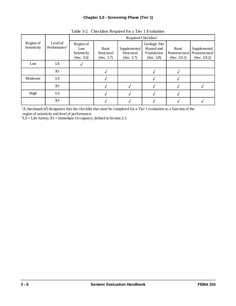
3.3 Selection and Use of Checklists
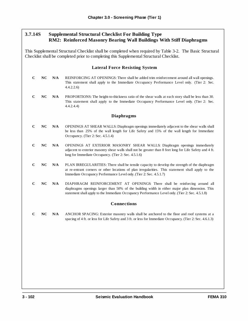
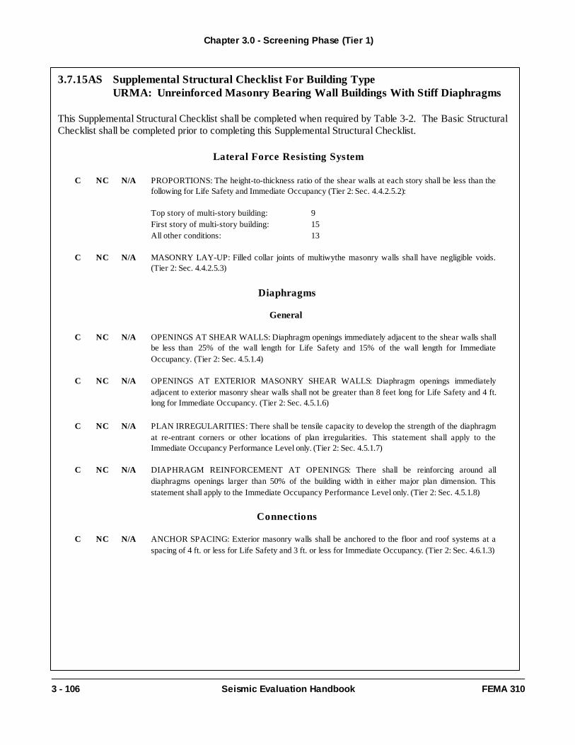
Required checklists, as a function of region ofseismicity and level of performance, are listed in Table3-2. Each of the required checklists designated inTable 3-2 shall be completed for a Tier 1 Evaluation.Each of the evaluation statements on the checklistsshall be marked "compliant" (C), "noncompliant" (NC),or "not applicable" (N/A). Compliant statements identifyissues that are acceptable according to the criteria ofthis Handbook, while non-compliant statements identifyissues that require further investigation. Certainstatements may not apply to the buildings beingevaluated.
Quick Checks for Tier 1 shall be performed inaccordance with Section 3.5 when necessary tocomplete an evaluation statement.
The Region of Low Seismicity Checklist, located inSection 3.6, shall be completed for buildings in regionsof low seismicity being evaluated to the Life SafetyPerformance Level. For buildings in regions of lowseismicity being evaluated to the Immediate OccupancyPerformance Level and buildings in regions ofmoderate or high seismicity, the appropriate Structural,Geologic Site Hazards, and Nonstructural Checklistsshall be completed in accordance with Table 3-2.
The appropriate Structural Checklists shall be selectedbased on the Common Building Types defined in Table2-2. The General Structural Checklists shall be usedfor buildings that cannot be classified as one of theCommon Building Types defined in Table 2-2.
A building with a different lateral-force-resisting systemin each principal direction shall use two sets ofstructural checklists, one for each direction. A buildingwith more than one type of lateral-force-resistingsystem along a single axis of the building shall beclassified as a mixed system. The General StructuralChecklists shall be used for this type of building.
Two separate Structural Checklists are provided foreach building type: a Basic Structural Checklist and aSupplemental Structural Checklist. As shown in Table3-2, the Basic Structural Checklist shall be completedfor buildings in regions of low seismicity beingevaluated to the Immediate Occupancy PerformanceLevel and buildings in regions of moderate and highseismicity. The Supplemental Structural Checklist shallbe completed in addition to the Basic StructuralChecklist for buildings in regions of moderate seismicitybeing evaluated to the Immediate OccupancyPerformance Level and buildings in regions of highseismicity.
The Geologic Site Hazards and Foundations Checklistshall be completed for all buildings except those inregions of low seismicity being evaluated to the LifeSafety Performance Level.
Two separate Nonstructural Checklists also areprovided: a Basic and Supplemental NonstructuralChecklist. As shown in Table 3-2, the BasicNonstructural Checklist shall be completed for allbuildings except those in regions of low seismicity beingevaluated to the Life Safety Performance Level. TheSupplemental Nonstructural Checklists shall becompleted in addition to the Basic NonstructuralChecklist for buildings in regions of moderate or highseismicity being evaluated to the Immediate OccupancyPerformance Level.
Chapter 3.0 - Screening Phase (Tier 1)
3 - 4 Seismic Evaluation Handbook FEMA 310
benchmark document. Knowledge that a code wasin effect at the time of construction is not sufficient.A statement on the drawings simply stating that itwas designed to the benchmark document will notsuffice. Sometimes, details in the existing buildingwill not correspond to the construction documents.Sometimes, the building is not properly detailed tomeet the benchmark document. This may occurdue to renovations or poor constructionmanagement. Only through a site visit, anexamination of existing documentation, and otherrequirements of Chapter 2 will the designprofessional be able to determine whether thestructure being evaluated complies with this section.
Commentary:
The evaluation statements provided in the checklistsform the core of the Tier 1 Evaluation Methodology.These evaluation statements are based on observedearthquake structural damage during actual
3.4 Further Evaluation Requirements
Upon completion of the Tier 1 Evaluation, furtherevaluation shall be conducted in accordance with Table3-3.
A Full-Building Tier 2 Evaluation shall be completed forbuildings with more than the number of stories listed inTable 3-3. 'NL' designates No Limit on the number ofstories.
A Full-Building Tier 2 Evaluation also is required forbuildings designated in Table 3-3 by 'T2'. A Tier 3Evaluation shall be required for buildings designated by'T3' in Table 3-3.
For buildings not requiring a Full-Building Tier 2Evaluation or a Tier 3 Evaluation, a Deficiency-OnlyTier 2 Evaluation may be conducted if potentialdeficiencies are identified by the Tier 1 Evaluation.Alternatively, the design professional may choose toend the investigation and report the deficiencies inaccordance with Chapter 1.
Chapter 3.0 - Screening Phase (Tier 1)
FEMA 310 Seismic Evaluation Handbook 3 - 5
during actual earthquakes. The checklists do notnecessarily identify the response of the structure toground motion; rather, the design professionalobtains a general sense of the structure'sdeficiencies and potential behavior during anearthquake. By quickly identifying the potentialdeficiencies in the structure, the design professionalhas an better idea of what to examine and analyzein a Tier 2 or Tier 3 Evaluation.
The General Structural Checklists are a completelisting of all evaluation statements used in Tier 1Evaluations. They should be used for buildings withstructural systems that do not match the commonbuilding types. While the general purpose of theTier 1 Checklists is to identify potential weak-linksin structures that have been observed in pastsignificant earthquakes, the General Checklists, byvirtue of their design, do not accomplish this. Theyonly represent a listing of all possible deficiencies.The design professional must consider first theapplicablility of the potential deficiency to thebuilding system being considered. Generally, onlythe deficiencies that participate in the yieldingelements of the building need be considered.
While the section numbers in parentheses followingeach evaluation statement correspond to Tier 2Evaluation procedures, they also correspond tocommentary in Chapter 4 regarding the statement'spurpose. If the design professional requiresadditional information on particular evaluationstatements, please refer to the commentaryassociated with the Tier 2 procedure for thatevaluation statement..
Commentary:
In most cases, the Tier 1 identification of potentialdeficiencies leads to further evaluation of only thesedeficiencies. As defined in Chapter 4, the requiredanalysis may be localized to the specific deficienciesor it may involve a global analysis to evaluate thespecific deficiency. Each checklist evaluationstatement concludes with a reference to theapplicable section in Chapter 4; the Tier 2procedures as well as commentary on thestatements' purpose.
The 'NL' designation for most buildings beingevaluated to the Life Safety Performance Level isconsistent with FEMA 178, which had no restrictionon the use of the checklists. The 'SP' designation forunreinforced masonry bearing wall buildings withflexible diaphragms also is consistent with FEMA178.
The 'T2,' 'T3,' and number of story designations inthe Immediate Occupancy Performance Levelcategory indicates that the building cannot bedeemed to meet the requirements of this Handbookwithout a full evaluation of the building. Based onpast performance of these types of buildings inearthquakes, the behavior of the structure must beexamined and understood. However, the Tier 1Checklists will provide insight and information aboutthe structure prior to a Tier 2 or Tier 3 Evaluation.
Table 3-2. Checklists Required for a Tier 1 Evaluation
Region ofSeismicity
Level ofPerformance2
Required Checklists1
Region ofLow
Seismicity(Sec. 3.6)
BasicStructural(Sec. 3.7)
SupplementalStructural(Sec. 3.7)
Geologic SiteHazard andFoundation(Sec. 3.8)
BasicNonstructural
(Sec. 3.9.1)
SupplementalNonstructural
(Sec. 3.9.2)
Low LS
IO
Moderate LS
IO
High LS
IO
1A checkmark ( ) designates that the checklist that must be completed for a Tier 1 evaluation as a function of the region of seismicity and level of performance.2LS = Life-Safety; IO = Immediate Occupancy; defined in Section 2.3.
Chapter 3.0 - Screening Phase (Tier 1)
3 - 6 Seismic Evaluation Handbook FEMA 310
Table 3-3. Further Evaluation Requirements1
Number of Stories beyond which aFull-Building Tier 2 Evaluation is Required
1A Full-Building Tier 2 or Tier 3 Evaluation shall be completed for buildings with more than the number of stories listed herein .SP - Special Procedure (A Tier 2 Evaluation is required using the Special Procedure defined in Section 4.2.6; the Geologic Site Hazards and
Foundations Checklist and the Nonstructural Checklist shall be completed prior to performing the Special Procedure Analysis) .NL - No Limit (No limit on the number of stories).T2 - Tier 2 (A Full-Building Tier 2 Evaluation is required; proceed to Chapter 4 ).T3 - Tier 3 (A Tier 3 Evaluation is required; proceed to Chapter 5 ).
Chapter 3.0 - Screening Phase (Tier 1)
3 - 8 Seismic Evaluation Handbook FEMA 310
3.5 Tier 1 Analysis
3.5.1 Overview
Analyses performed as part of Tier 1 of the EvaluationProcess are limited to Quick Checks. Quick Checks shall be used to calculate the stiffness and strength of certain building components to determine whether thebuilding complies with certain evaluation criterion. Quick Checks shall be performed in accordance withSection 3.5.3 when triggered by evaluation statementsfrom the Checklists of Section 3.7. Seismic shearforces for use in the Quick Checks shall be computedin accordance with Section 3.5.2.
3.5.2 Seismic Shear Forces
3.5.2.1 Pseudo Lateral Force
The pseudo lateral force, in a given horizontal directionof a building, shall be calculated in accordance withEquations (3-1) and (3-2).
V=CSaW (3-1)where:
V = Pseudo lateral force;C = Modification factor to relate expected
maximum inelastic displacements to displacements calculated for linear elasticresponse; C shall be taken from Table 3-4;
Sa = Response spectral acceleration at the fundamental period of the building in thedirection under consideration. The value ofSa shall be calculated in accordance with theprocedures in Section 3.5.2.3.
W = Total dead load and anticipated live load asfollows:
In storage and warehouse occupancies,a minimum of 25% of the floor live load;The actual partition weight or minimumweight of 10 psf of floor area, whicheveris greater;The applicable snow load;The total weight of permanent equipmentand furnishings.
Alternatively, for buildings with shallow foundationsand without basements being evaluated for the LifeSafety Performance Level, Equation (3-2) may be usedto compute the pseudo lateral force:
V = 0.75W (3-2)
If Equation (3-2) is used, an m-factor of 1.0 shall be used to compute the component forces and stresses forthe Quick Checks of Section 3.5.3 and acceptancecriteria of Section 4.2.4.
Commentary: The seismic evaluation procedure of this Handbook,as well as the NEHRP Recommended Provisionsfor Seismic Regulations for New Buildings andthe Uniform Building Code, is based on awidely-accepted philosophy that permits nonlinearresponse of a building when subjected to a groundmotion that is representative of the designearthquake. The NEHRP RecommendedProvisions for Seismic Regulations for NewBuildings, the Uniform Building Code andFEMA 178 account for nonlinear seismic responsein a linear static analysis procedure by including aresponse modification factor, R, in calculating areduced equivalent base shear to produce a roughapproximation of the internal forces during a designearthquake. In other words, the base shear isequivalent to what the bulding is expected to resiststrength-wise, but the building displacement usingthis base shear are significantly less than thedisplacements the building will actually experienceduring a design earthquake. Thus, this approach
3.5.2.2 Story Shear Forces
For multi-story buildings, the pseudo lateral forcecomputed in accordance with Section 3.5.2.1 shall be distributed vertically in accordance with Equation (3-3).
(3-3) Vj =
n+ jn+ 1
Wj
WV
where: Vj = Story shear at story level j,n = Total number of stories above ground level,j = Number of story level under consideration,Wj = Total seismic weight of all stories above level
j,W = Total seismic weight per Section 3.5.2.1,V = Pseudo lateral force from Equation (3-1) or
(3-2).
For buildings with flexible diaphragms (Types S1A,S2A, S5A, C2A, C3A, PC1, RM1, URM), story shearshall be calculated separately for each line of lateralresistance. This value shall be calculated usingEquation (3-3) with Wj defined as the seismic weightof all stories above level j tributary to the line ofresistance under consideration.
3.5.2.3 Spectral Acceleration
Spectral acceleration for use in computing the pseudo lateral force shall be computed in accordance with thissection. Spectral acceleration shall be based onmapped spectral accelerations, defined in Section3.5.2.3.1, for the site of the building being evaluated.Alternatively, a site specific response spectrum may bedeveloped according to Section 3.5.2.3.2.
3.5.2.3.1 Mapped Spectral Acceleration
The mapped spectral acceleration, Sa, shall becomputed in accordance with Equation (3-4).
Sa = , but (3-4)SD1
TSa shall not exceed SDS ;
where: SD1 = FvS1 (3-5)2
3SDS = FaSs (3-6)2
3
Chapter 3.0 - Screening Phase (Tier 1)
FEMA 310 Seismic Evaluation Handbook 3 - 9
increases the base shear by another factor (Cd ,.7R, etc.) when checking drift and ductilityrequirements. In summary, this procedure is basedon equivalent lateral forces and pseudodisplacements.
The linear static analysis procedure in thisHandbook, as well as in FEMA 273, takes adifferent approach to account for the nonlinearseismic response. Pseudo static lateral forces areapplied to the structure to obtain "actual"displacements during a design earthquake. Thepseudo lateral force of Equation (3-1) representsthe force required, in a linear static analysis, toimpose the expected actual deformation of thestructure in its yielded state when subjected to thedesign earthquake motions.
It does not represent an actual lateral force thatthe building must resist in traditional design codesor FEMA 178. In summary, this procedure isbased on equivalent displacements and pseudolateral forces. For additional commentaryregarding this linear static analysis approach,please refer to the commentary for Section 4.2.2.1and FEMA 273 and 274.
Instead of applying a ductility related responsereduction factor, R, to the applied loads, thisHandbook uses ductility related m-factors in theacceptability checks of each component. Thus,instead of using a single R-value for the entirestructure, different m-factors are used dependingon the ductility of the component being evaluated.The m-factors specified for each Tier of analysisshall not be used for other Tiers of analysis (i.e.,Tier 3 values of m may not be used when a Tier 1or Tier 2 analysis is performed).
For short and stiff buildings with low ductilitylocated in regions of high seismicity, the requiredbuilding strength in accordance with Equation (3-1)may exceed the force required to cause sliding atthe foundation level. The strength of the structure,however, does not need to exceed the strength ofthe ground. Thus, when Equation (3-2) is appliedto these buildings, the required strength ofstructural components need not exceed 0.75W.
T = Fundamental period of vibration of thebuilding calculated in accordance withSection 3.5.2.4.
Ss and S1 are short period response acceleration andspectral response acceleration at a one second periodparameters, respectively, for the Maximum ConsideredEarthquake (MCE). Ss and S1 shall be obtained fromthe Seismic Map Package. Fv and Fa are sitecoefficients and shall be determined from Tables 3-5and 3-6, respectively, based on the site class and thevalues of the response acceleration parameters Ss andS1. The site class of the building shall be defined as oneof the following:
Class A : Hard rock with measured shearwave velocity, > 5,000 ft/sec; νs
Class B : Rock with 2,500 ft/sec < < 5,000νs ft/sec. Class C: Very dense soil and soft rock with 1,200 ft/sec < < 2,500 ft/sec or with either νs
standard blow count > 50 or undrained shearNstrength > 2,000 psf. su
Class D: Stiff soil with 600 ft/sec < <νs
1,200 ft/sec or with 15 < < 50 or 1,000 psfN< < 2000 psf. suClass E: Any profile with more than 10 feetof soft clay defined as soil with plasticity indexPI >20, or water content w > 40 percent, and
< 500 psf or a soil profile with < 600su νsft/sec.Class F: Soils requiring a site-specific geotechnical investigation and dynamic siteresponse analyses:- Soils vulnerable to potential failure or
collapse under seismic loading, such asliquefiable soils, quick and highly-sensitiveclays, collapsible weakly-cemented soils;
- Peats and/or highly organic clays (H>10feet of peat and/or highly organic clay;where H = thickness of soil);
- Very high plasticity clays (H > 25 feet withPI > 75 percent);
- Very thick soft/medium stiff clays (H >120 feet).
For a soil profile classified as Class F, a Class E soilprofile may be assumed for a Tier 1 Evaluation. Ifsufficient data is not available to classify a soil profile, a
Class E profile shall be assumed. For one- andtwo-story buildings with a roof height equal to or lessthan 25 feet, a Class D soil profile may be assumed ifsite conditions are not known.
Table 3-5. Values of Fv as a Function of Site Classand Mapped Spectral Acceleration at a One Second
Period, S1
SiteClass
Mapped Spectral Acceleration at One SecondPeriod1
S1< 0.1 S1= 0.2 S1 = 0.3 S1 = 0.4 S1> 0.5
A 0.8 0.8 0.8 0.8 0.8
B 1.0 1.0 1.0 1.0 1.0
C 1.7 1.6 1.5 1.4 1.3
D 2.4 2.0 1.8 1.6 1.5
E 3.5 3.4 2.8 2.4 2.2
F * * * * *
1Note: Use straight-line interpolation for intermediatevalues of S1.* See Class F soil profile.
Table 3-6. Values of Fa as a Function of Site Classand Mapped Short-Period Spectral Acceleration, Ss
SiteClass
Mapped Spectral Acceleration at Short Periods1
Ss < 0.25 Ss = 0.50 Ss = 0.75 Ss = 1.00 Ss > 1.25
A 0.8 0.8 0.8 0.8 0.8
B 1.0 1.0 1.0 1.0 1.0
C 1.2 1.2 1.1 1.0 1.0
D 1.6 1.4 1.2 1.1 1.0
E 2.5 1.7 1.2 0.9 0.9
F * * * * *1NOTE: Use straight-line interpolation for intermediate values of Ss. *See Class F soil profile.
Chapter 3.0 - Screening Phase (Tier 1)
3 - 10 Seismic Evaluation Handbook FEMA 310
3.5.2.3.2 Site-Specific Spectral Acceleration
Development of site-specific response spectra shall bebased on the geologic, seismological, and soil characteristics associated with the specific site of the building being evaluated. Site-specific responsespectra shall be based on input ground motions with a2% probability of exceedance in 50 years (2500 yearreturn interval) and developed for an equivalent viscousdamping ratio of 5%. The site specific responsespectra need not exceed the mean deterministicspectra for faults with known slip rates. When the 5%damped site specific spectrum has spectral amplitudesin the period range of greatest significance to thestructural response that are less than 70% of themapped spectral amplitudes, an independent third-partyreview of the spectrum shall be made by an individualwith expertise in the evaluation of ground motion.
3.5.2.4 Period
The fundamental period of a building, in the direction under consideration, shall be calculated in accordancewith Equation (3-7).
T = Cthn3/4 (3-7)
where:
T = Fundamental period (in seconds) in thedirection under consideration;
Ct = 0.060 for wood buildings (Building TypesW1, W1A, and W2);
= 0.035 for moment-resisting frame systems ofsteel (Building Types S1 and S1A);
= 0.030 for moment-resisting frames of reinforced concrete (Building Type C1);
= 0.030 for eccentrically-braced steel frames(Building Types S2 and S2A);
= 0.020 for all other framing systems;hn = height (in feet) above the base to the roof
level.
Alternatively, for steel or reinforced-concrete momentframes of 12 stories or less the fundamental period ofthe building may be calculated as follows:
T=0.10N (3-8) where:
N = number of stories above the base.
3.5.3 Quick Checks for Strength and Stiffness
Quick Checks shall be used to compute the stiffnessand strength of building components. Quick Checksare triggered by evaluation statements in the Checklistsof Section 3.7 and are required to determine thecompliance of certain building components. Theseismic shear forces used in the Quick Checks shall becalculated in accordance with Section 3.5.2.
3.5.3.1 Story Drift for Moment Frames
Equation (3-9) shall be used to calculate the drift ratiosof regular, multistory, multibay moment frames withcolumns continuous above and below the story underconsideration. The drift ratio is based on the deflectiondue to flexural displacement of a representativecolumn, including the effect of end rotation due tobending of the representative girder.
DR = (3-9)
kb+ kc
kb⋅kc
h12E
Vc
where: DR = Drift Ratio = Interstory displacement
divided by story height,kb = I/L for the representative beam,kc = I/h for the representative column,h = Story height (in.),I = Moment of inertia (in4),
Chapter 3.0 - Screening Phase (Tier 1)
FEMA 310 Seismic Evaluation Handbook 3 - 11
Commentary:
The quick check equations used here are essentiallythe same as those used in FEMA 178, modified foruse with the pseudo lateral forces and theappropriate material m-factors.
Commentary: The short period response acceleration andspectral response acceleration at a one secondperiod parameters, Ss and S1 , are provided in theSeismic Map Package. The values of Ss and S1represent an earthquake with a 2% probability ofexceedance in 50 years with deterministic-basedmaximum values near known fault sources. Forinformation on obtaining a copy of the SeismicMap Package, please contact the FEMADistribution Facility at 1-800-480-2520.
L = Center to center length of columns (in.),E = Modulus of elasticity (ksi),Vc = Shear in the column (kips).
The column shear forces shall be taken as a portion ofthe story shear forces, computed in accordance withSection 3.5.2.2. For reinforced concrete frames, anequivalent cracked section moment of inertia equal toone half of gross value shall be used.
Equation (3-9) may also be used for the first floor ofthe frame if columns are fixed against rotation at thebottom. However, if columns are pinned at the bottom,an equivalent story height equal to twice the actualstory height shall be used in calculating the value of kc.
For other configurations of frames, the quick checkneed not be performed as a Full-Building Tier 2Evaluation including calculation of the drift ratio shallbe completed based on principles of structuralmechanics.
3.5.3.2 Shear Stress in Concrete Frame Columns
The average shear stress, vavg, in the columns of concrete frames shall be computed in accordance withEquation (3-10).
vavg = (3-10) 1m
ncnc− nf
Vj
Ac
where: nc = Total number of columns;nf = Total number of frames in the direction of
loading;Ac = Summation of the cross sectional area of all
columns in the story under consideration;and
Vj = Story shear computed in accordance withSection 3.5.2.2.
m = component modification factor; m shall betaken equal to 2.0 for buildings beingevaluated to the Life Safety PerformanceLevel and 1.3 for buildings being evaluated tothe Immediate Occupancy PerformanceLevel.
3.5.3.3 Shear Stress in Shear Walls
The average shear stress in shear walls, vavg, shall becalculated in accordance with Equation (3-11).
vavg = (3-11) 1m
Vj
A w
where: Vj = Story shear at level j computed in
accordance with Section 3.5.2.2;Aw = Summation of the horizontal cross sectional
area of all shear walls in the direction ofloading. Openings shall be taken intoconsideration when computing Aw. Formasonry walls, the net area shall be used.For wood framed walls, the length shall beused rather than the area.
m = component modification factor; m shall betaken from Table 3-7.
Table 3-7. m-factors for Shear Walls
Wall TypeLevel of
Performance1
LS IO
Reinforced Concrete,Precast Concrete, and
Wood
4.0 2.0
Reinforced Masonry 3.0 1.5
Unreinforced Masonry 1.5 N/A
1Defined in Section 2.4.
3.5.3.4 Diagonal Bracing
The average axial stress in diagonal bracing elements,fbr, shall be calculated in accordance with Equation(3-12).
fbr = (3-12) 1m
Vj
sNbr
Lbr
Abr
where: Lbr = Average length of the braces (ft);Nbr= Number of braces in tension and
compression if the braces are designed forcompression; if not, use the number ofbraces in tension, if the braces are notdesigned for compression;
s = Average span length of braced spans (ft);Abr= Average area of a diagonal brace (in2);
Chapter 3.0 - Screening Phase (Tier 1)
3 - 12 Seismic Evaluation Handbook FEMA 310
Commentary: Equation (3-10) assumes that all of the columns inthe frame have similar stiffness.
Vj = Maximum story shear at each level (kips);m = component modification factor; m shall be
taken from Table 3-8.
Table 3-8. m-factors for Diagonal Braces
Brace Type (d/t) *
Level ofPerformance1
LS IO
Tube < 90/(Fye)1/2 6.0 2.5
> 190/(Fye)1/2 3.0 1.5
Pipe < 1500/Fye 6.0 2.5
> 6000/Fye 3.0 1.5
Tension-only 3.0 1.5
All others 6.0 2.5
1Defined in Section 2.4.*Interpolation permitted.Fye = 1.25Fy; expected yield stress as defined by
Section 4.2.4.4.
3.5.3.5 Precast ConnectionsThe precast connection in precast concrete momentframes shall be able to develop the moment in thegirder, Mg , calculated in accordance with Equation(3-13).
Mg = (3-13)
where:nc = Total number of columns;nf = Total number of frames in the direction of
loading;Vj = Story shear at the level directly below the
connection under consideration;h = Typical column story height;m = Component modification factor taken equal
to 2.0 for buildings being evaluated to theLife Safety Performance Level and 1.3 forbuildings being evaluated to the ImmediateOccupancy Performance Level.
3.5.3.6 Axial Stress Due to Overturning
The axial stress of columns subjected to overturningforces, pot, shall be calculated in accordance withEquation (3-14).
pot = (3-14)
where:nf = Total number of frames in the direction of
loading;V = Pseudo lateral force;hn = height (in feet) above the base to the roof
level.L = Total length of the frame (in feet);m = Component modification factor taken equal
to 2.0 for buildings being evaluated to theLife Safety Performance Level and 1.3 forbuildings being evaluated to the ImmediateOccupancy Performance Level.
Chapter 3.0 - Screening Phase (Tier 1)
FEMA 310 Seismic Evaluation Handbook 3 - 13
Vj
m
ncnc − nf
h2
1m
23
Vhn
Lnf
Chapter 3.0 - Screening Phase (Tier 1)
3 - 14 Seismic Evaluation Handbook FEMA 310
3.6 Region Of Low Seismicity Checklist
This Region of Low Seismicity Checklist shall be completed when required by Table 3-2.
Each of the evaluation statements on this checklist shall be marked compliant (C), non-compliant (NC), or notapplicable (N/A) for a Tier 1 Evaluation. Compliant statements identify issues that are acceptable accordingto the criteria of this Handbook, while non-compliant statements identify issues that require furtherinvestigation. Certain statements may not apply to the buildings being evaluated. For non-compliantevaluation statements, the design professional may choose to conduct further investigation using thecorresponding Tier 2 evaluation procedure; the section numbers in parentheses following each evaluationstatement correspond to Tier 2 evaluation procedures.
Structural Components
C NC N/A LOAD PATH: The structure shall contain one complete load path for seismic force effects from anyhorizontal direction that serves to transfer the inertial forces from the mass to the foundation. (Tier2: Sec. 4.3.1.1)
C NC N/A WALL ANCHORAGE: Exterior concrete or masonry walls shall be anchored for out-of-planeforces at each diaphragm level with steel anchors or straps that are developed into the diaphragm.(Tier 2: Sec. 4.6.1.1)
Geologic Site and Foundation Components
C NC N/A FOUNDATION PERFORMANCE: There shall be no evidence of excessive foundation movementsuch as settlement or heave that would affect the integrity or strength of the structure. (Tier 2: Sec.4.7.2.1)
Nonstructural Components
C NC N/A EMERGENCY LIGHTING: Emergency lighting equipment shall be anchored to prevent falling orswaying during an earthquake. (Tier 2: Sec. 4.8.3.2)
C NC N/A CLADDING ANCHORS: Cladding components weighing more than 10 psf shall be anchored tothe exterior wall framing at a spacing equal to or less than 6 ft. (Tier 2: Sec. 4.8.4.1)
C NC N/A GLAZING: Glazing in curtain walls and individual panes over 16 square feet in area, located up to aheight of 10 feet above an exterior walking surface, shall be laminated annealed or heat strengthenedsafety glass that will remain in the frame when cracked. (Tier 2: Sec. 4.8.4.9)
C NC N/A PARAPETS: There shall be no laterally unsupported unreinforced masonry parapets or cornicesabove the highest anchorage level with height-to-thickness ratios greater than 2.5. (Tier 2: Sec.4.8.8.1)
C NC N/A CANOPIES: Canopies located at building exits shall be anchored at a spacing of 10 ft. (Tier 2: Sec.4.8.8.2)
C NC N/A STAIRS: Walls around stair enclosures shall not consist of unbraced hollow clay tile or unreinforcedmasonry. (Tier 2: Sec. 4.8.10.1)
C NC N/A EMERGENCY POWER: Equipment used as part of an emergency power system shall beanchored. (Tier 2: Sec. 4.8.12.1)
3.7 Structural Checklists
This section provides Basic and Supplemental Structural Checklists for the following building types:
W1: Wood Light FramesW1A: Multi-Story, Multi-Unit Residential Wood Frames W2: Wood Frames, Commercial and IndustrialS1: Steel Moment Frames with Stiff DiaphragmsS1A: Steel Moment Frames with Flexible DiaphragmsS2: Steel Braced Frames with Stiff DiaphragmsS2A: Steel Braced Frames with Flexible DiaphragmsS3: Steel Light FramesS4: Steel Frames with Concrete Shear WallsS5: Steel Frames with Infill Masonry Shear Walls and Stiff DiaphragmsS5A: Steel Frames with Infill Masonry Shear Walls and Flexible DiaphragmsC1: Concrete Moment FramesC2: Concrete Shear Wall Buildings with Stiff DiaphragmsC2A: Concrete Shear Wall Buildings with Flexible DiaphragmsC3: Concrete Frames with Infill Masonry Shear Walls and Stiff DiaphragmsC3A: Concrete Frames with Infill Masonry Shear Walls and Flexible DiaphragmsPC1: Precast/Tilt-up Concrete Shear Wall Buildings with Flexible DiaphragmsPC1A: Precast/Tilt-up Concrete Shear Wall Buildings with Stiff DiaphragmsPC2: Precast Concrete Frames with Shear WallsPC2A: Precast Concrete Frames without Shear WallsRM1: Reinforced Masonry Bearing Wall Buildings with Flexible DiaphragmsRM2: Reinforced Masonry Bearing Wall Buildings with Stiff DiaphragmsURMA: Unreinforced Masonry Bearing Wall Buildings with Stiff Diaphragms
General Basic Structural ChecklistGeneral Supplemental Structural Checklist
For a description of the specific building types listed above, refer to Table 2-2.
The appropriate Basic Structural Checklist shall be completed when required by Table 3-2.
The appropriate Supplemental Structural Checklist shall be completed when required by Table 3-2. Theappropriate Basic Structural Checklist shall be completed prior to completing the appropriate SupplementalStructural Checklist.
Chapter 3.0 - Screening Phase (Tier 1)
FEMA 310 Seismic Evaluation Handbook 3 - 15
Chapter 3.0 - Screening Phase (Tier 1)
3 - 16 Seismic Evaluation Handbook FEMA 310
3.7.1 Basic Structural Checklist for Building Type W1: Wood Light Frames
This Basic Structural Checklist shall be completed when required by Table 3-2.
Each of the evaluation statements on this checklist shall be marked compliant (C), non-compliant (NC), or notapplicable (N/A) for a Tier 1 Evaluation. Compliant statements identify issues that are acceptable accordingto the criteria of this Handbook, while non-compliant statements identify issues that require furtherinvestigation. Certain statements may not apply to the buildings being evaluated. For non-compliantevaluation statements, the design professional may choose to conduct further investigation using thecorresponding Tier 2 evaluation procedure; the section numbers in parentheses following each evaluationstatement correspond to Tier 2 evaluation procedures.
Building System
C NC N/A LOAD PATH: The structure shall contain one complete load path for Life Safety and ImmediateOccupancy for seismic force effects from any horizontal direction that serves to transfer the inertialforces from the mass to the foundation. (Tier 2: Sec. 4.3.1.1)
C NC N/A VERTICAL DISCONTINUITIES: All vertical elements in the lateral-force-resisting system shall becontinuous to the foundation. (Tier 2: Sec. 4.3.2.4)
C NC N/A DETERIORATION OF WOOD: There shall be no signs of decay, shrinkage, splitting, fire damage, orsagging in any of the wood members and none of the metal accessories shall be deteriorated, broken, orloose. (Tier 2: Sec. 4.3.3.1)
C NC N/A OVERDRIVEN FASTENERS: There shall be no evidence of overdriven fasteners in the shear walls.(Tier 2: Sec. 4.3.3.2)
Lateral Force Resisting System
C NC N/A REDUNDANCY: The number of lines of shear walls in each principal direction shall be greater thanor equal to 2 for Life Safety and Immediate Occupancy. (Tier 2: Sec. 4.4.2.1.1)
Commentary:
These buildings are single or multiple family dwellings of one or more stories in height. Building loads arelight and the framing spans are short. Floor and roof framing consists of closely spaced wood joists orrafters on wood studs. The first floor framing is supported directly on the foundation, or is raised up oncripple studs and post and beam supports. The foundation consists of spread footings constructed ofconcrete, concrete masonry block, or brick masonry in older construction. Chimneys, when present,consist of solid brick masonry, masonry veneer, or wood frame with internal metal flues. Lateral forcesare resisted by wood frame diaphragms and shear walls. Floor and roof diaphragms consist of straight ordiagonal wood sheathing, tongue and groove planks, or plywood. Shear walls consist of straight ordiagonal wood sheathing, plank siding, plywood, stucco, gypsum board, particle board, or fiberboard.Interior partitions are sheathed with plaster or gypsum board.
Chapter 3.0 - Screening Phase (Tier 1)
FEMA 310 Seismic Evaluation Handbook 3 - 17
C NC N/A SHEAR STRESS CHECK: The shear stress in the shear walls, calculated using the Quick Checkprocedure of Section 3.5.3.3, shall be less than the following values for Life Safety and ImmediateOccupancy (Tier 2: Sec. 4.4.2.7.1):
C NC N/A STUCCO (EXTERIOR PLASTER) SHEAR WALLS: Multistory buildings shall not rely on exteriorstucco walls as the primary lateral-force-resisting system. (Tier 2: Sec. 4.4.2.7.2)
C NC N/A GYPSUM WALLBOARD OR PLASTER SHEAR WALLS: Interior plaster or gypsum wallboardshall not be used as shear walls on buildings over one story in height. (Tier 2: Sec. 4.4.2.7.3)
C NC N/A NARROW WOOD SHEAR WALLS: Narrow wood shear walls with an aspect ratio greater than 2 to1 for Life Safety and 1.5 to 1 for Immediate Occupancy shall not be used to resist lateral forcesdeveloped in the building. ( Tier 2: Sec. 4.4.2.7.4)
C NC N/A WALLS CONNECTED THROUGH FLOORS: Shear walls shall have interconnection betweenstories to transfer overturning and shear forces through the floor. (Tier 2: Sec. 4.4.2.7.5)
C NC N/A HILLSIDE SITE: For a sloping site greater than one-half story, all shear walls on the downhill slopeshall have an aspect ratio less than 1 to 1 for Life-Safety and 1 to 2 for Immediate Occupancy. (Tier2: Sec. 4.4.2.7.6)
C NC N/A CRIPPLE WALLS: All cripple walls below first floor level shear walls shall be braced to thefoundation with shear elements. (Tier 2: Sec. 4.4.2.7.7)
Connections
C NC N/A WOOD POSTS: There shall be a positive connection of wood posts to the foundation. ( Tier 2: Sec.4.6.3.3)
C NC N/A WOOD SILLS: All wood sill s shall be bolted to the foundation. ( Tier 2: Sec. 4.6.3.4)
C NC N/A GIRDER/COLUMN CONNECTION: There shall be a positive connection between the girder andthe column support. ( Tier 2: Sec. 4.6.4.1)
Chapter 3.0 - Screening Phase (Tier 1)
3 - 18 Seismic Evaluation Handbook FEMA 310
3.7.1S Supplemental Structural Checklist For Building Type W1: Wood Light Frames
This Supplemental Structural Checklist shall be completed when required by Table 3-2. The Basic StructuralChecklist shall be completed prior to completing this Supplemental Structural Checklist.
Lateral Force Resisting System
C NC N/A OPENINGS: Walls with garage doors or other large openings shall be braced with plywood shearwalls or shall be supported by adjacent construction through substantial positive ties. This statementshall apply to the Immediate Occupancy Performance Level only. (Tier 2: Sec 4.4.2.7.8)
C NC N/A HOLD-DOWN ANCHORS: All walls shall have properly constructed hold-down anchors. Thisstatement shall apply to the Immediate Occupancy Performance Level only. (Tier 2: Sec 4.4.2.7.9)
Diaphragms
C NC N/A DIAPHRAGM CONTINUITY: The diaphragms shall not be composed of split-level floors. Inwood buildings, the diaphragms shall not have expansion joints. (Tier 2: Sec. 4.5.1.1)
C NC N/A ROOF CHORD CONTINUITY: All chord elements shall be continuous, regardless of changes inroof elevation. (Tier 2: Sec. 4.5.1.3)
C NC N/A PLAN IRREGULARITIES: There shall be tensile capacity to develop the strength of the diaphragmat re-entrant corners or other locations of plan irregularities. This statement shall apply to theImmediate Occupancy Performance Level only. (Tier 2: Sec. 4.5.1.7)
C NC N/A DIAPHRAGM REINFORCEMENT AT OPENINGS: There shall be reinforcing around alldiaphragms openings larger than 50% of the building width in either major plan dimension. Thisstatement shall apply to the Immediate Occupancy Performance Level only. (Tier 2: Sec. 4.5.1.8)
C NC N/A STRAIGHT SHEATHING: All straight sheathed diaphragms shall have aspect ratios less than 2 to 1for Life Safety and 1 to 1 for Immediate Occupancy in the direction being considered. (Tier 2: Sec.4.5.2.1)
C NC N/A SPANS: All wood diaphragms with spans greater than 24 ft. for Life Safety and 12 ft. for ImmediateOccupancy shall consist of wood structural panels or diagonal sheathing. Wood commercial andindustrial buildings may have rod-braced systems. (Tier 2: Sec. 4.5.2.2)
C NC N/A UNBLOCKED DIAPHRAGMS: All unblocked wood structural panel diaphragms shall havehorizontal spans less than 40 ft. for Life Safety and 25 ft. for Immediate Occupancy and shall haveaspect ratios less than or equal to 4 to 1 for Life Safety and 3 to 1 for Immediate Occupancy. (Tier 2:Sec. 4.5.2.3)
C NC N/A OTHER DIAPHRAGMS: The diaphragm shall not consist of a system other than those described inSection 4.5. (Tier 2: Sec. 4.5.7.1)
Connections
C NC N/A WOOD SILL BOLTS: Sill bolts shall be spaced at 6 ft. or less for Life Safety and 4 ft. or less forImmediate Occupancy, with proper edge distance provided for wood and concrete. (Tier 2: Sec.4.6.3.9)
Chapter 3.0 - Screening Phase (Tier 1)
FEMA 310 Seismic Evaluation Handbook 3 - 19
This Page IntentionallyLeft Blank
Chapter 3.0 - Screening Phase (Tier 1)
3 - 20 Seismic Evaluation Handbook FEMA 310
3.7.1A Basic Structural Checklist For Building Type W1A: Multi-Story, Multi-UnitResidential Wood Frames
This Basic Structural Checklist shall be completed when required by Table 3-2.
Each of the evaluation statements on this checklist shall be marked compliant (C), non-compliant (NC), or notapplicable (N/A) for a Tier 1 Evaluation. Compliant statements identify issues that are acceptable accordingto the criteria of this Handbook, while non-compliant statements identify issues that require furtherinvestigation. Certain statements may not apply to the buildings being evaluated. For non-compliantevaluation statements, the design professional may choose to conduct further investigation using thecorresponding Tier 2 evaluation procedure; the section numbers in parentheses following each evaluationstatement correspond to Tier 2 evaluation procedures.
Building System
C NC N/A LOAD PATH: The structure shall contain one complete load path for Life Safety and ImmediateOccupancy for seismic force effects from any horizontal direction that serves to transfer the inertialforces from the mass to the foundation. (Tier 2: Sec. 4.3.1.1)
C NC N/A WEAK STORY: The strength of the lateral-force-resisting system in any story shall not be less than80% of the strength in an adjacent story above or below for Life-Safety and Immediate Occupancy.(Tier 2: Sec. 4.3.2.1)
C NC N/A SOFT STORY: The stiffness of the lateral-force-resisting system in any story shall not be less than70% of the stiffness in an adjacent story above or below or less than 80% of the average stiffness ofthe three stories above or below for Life-Safety and Immediate Occupancy. (Tier 2: Sec. 4.3.2.2)
C NC N/A VERTICAL DISCONTINUITIES: All vertical elements in the lateral-force-resisting system shall becontinuous to the foundation. (Tier 2: Sec. 4.3.2.4)
C NC N/A DETERIORATION OF WOOD: There shall be no signs of decay, shrinkage, splitting, fire damage,or sagging in any of the wood members and none of the metal accessories shall be deteriorated,broken, or loose. (Tier 2: Sec. 4.3.3.1)
Commentary:
These buildings are single or multiple family dwellings of one or more stories in height with open frontgarages at the first story. Building loads are light and the framing spans are short. Floor and roof framingconsists of closely spaced wood joists or rafters on wood studs. The first story consists of wood floorframing on wood stud walls and steel pipe columns, or a concrete slab on concrete or concrete masonryblock walls. The foundation consists of spread footings constructed of concrete, concrete masonry block,or brick masonry in older construction. Chimneys, when present, consist of solid brick masonry, masonryveneer, or wood frame with internal metal flues. Lateral forces are resisted by wood frame diaphragmsand shear walls. Floor and roof diaphragms consist of straight or diagonal wood sheathing, tongue andgroove planks, or plywood. Shear walls consist of straight or diagonal wood sheathing, plank siding,plywood, stucco, gypsum board, particle board, or fiberboard. Interior partitions are sheathed with plasteror gypsum board.
Chapter 3.0 - Screening Phase (Tier 1)
FEMA 310 Seismic Evaluation Handbook 3 - 21
C NC N/A OVERDRIVEN FASTENERS: There shall be no evidence of overdriven fasteners in the shear walls .(Tier 2: Sec. 4.3.3.2)
Lateral Force Resisting System
C NC N/A REDUNDANCY: The number of lines of shear walls in each principal direction shall be greater thanor equal to 2 for Life Safety and Immediate Occupancy. (Tier 2: Sec. 4.4.2.1.1)
C NC N/A SHEAR STRESS CHECK: The shear stress in the shear walls, calculated using the Quick Checkprocedure of Section 3.5.3.3, shall be less than the following values for Life Safety and ImmediateOccupancy (Tier 2: Sec. 4.4.2.7.1):
C NC N/A STUCCO (EXTERIOR PLASTER) SHEAR WALLS: Multistory buildings shall not rely on exteriorstucco walls as the primary lateral-force-resisting system. (Tier 2: Sec. 4.4.2.7.2)
C NC N/A GYPSUM WALLBOARD OR PLASTER SHEAR WALLS: Interior plaster or gypsum wallboardshall not be used as shear walls on buildings over one story in height. (Tier 2: Sec. 4.4.2.7.3)
C NC N/A NARROW WOOD SHEAR WALLS: Narrow wood shear walls with an aspect ratio greater than 2 to1 for Life Safety and 1.5 to 1 for Immediate Occupancy shall not be used to resist lateral forcesdeveloped in the building. ( Tier 2: Sec. 4.4.2.7.4)
C NC N/A WALLS CONNECTED THROUGH FLOORS: Shear walls shall have interconnection betweenstories to transfer overturning and shear forces through the floor. (Tier 2: Sec. 4.4.2.7.5)
C NC N/A HILLSIDE SITE: For a sloping site greater than one-half story, all shear walls on the downhill slopeshall have an aspect ratio less than 1 to 1 for Life-Safety and 1 to 2 for Immediate Occupancy. (Tier2: Sec. 4.4.2.7.6)
C NC N/A CRIPPLE WALLS: All cripple walls below first floor level shear walls shall be braced to thefoundation with shear elements. (Tier 2: Sec. 4.4.2.7.7)
Connections
C NC N/A WOOD POSTS: There shall be a positive connection of wood posts to the foundation. ( Tier 2: Sec.4.6.3.3)
C NC N/A WOOD SILLS: All wood sill s shall be bolted to the foundation. ( Tier 2: Sec. 4.6.3.4)
C NC N/A GIRDER/COLUMN CONNECTION: There shall be a positive connection between the girder andthe column support. ( Tier 2: Sec. 4.6.4.1)
Chapter 3.0 - Screening Phase (Tier 1)
3 - 22 Seismic Evaluation Handbook FEMA 310
3.7.1AS Supplemental Structural Checklist For Building Type W1A: Multi-Story, Multi-UnitResidential Wood Frames
This Supplemental Structural Checklist shall be completed when required by Table 3-2. The Basic StructuralChecklist shall be completed prior to completing this Supplemental Structural Checklist.
Lateral Force Resisting System
C NC N/A OPENINGS: Walls with garage doors or other large openings shall be braced with plywood shearwalls or shall be supported by adjacent construction through substantial positive ties. This statementshall apply to the Immediate Occupancy Performance Level only. (Tier 2: Sec 4.4.2.7.8)
C NC N/A HOLD-DOWN ANCHORS: All walls shall have properly constructed hold-down anchors. Thisstatement shall apply to the Immediate Occupancy Performance Level only. (Tier 2: Sec 4.4.2.7.9)
Diaphragms
C NC N/A DIAPHRAGM CONTINUITY: The diaphragms shall not be composed of split-level floors. Inwood buildings, the diaphragms shall not have expansion joints. (Tier 2: Sec. 4.5.1.1)
C NC N/A ROOF CHORD CONTINUITY: All chord elements shall be continuous, regardless of changes inroof elevation. (Tier 2: Sec. 4.5.1.3)
C NC N/A PLAN IRREGULARITIES: There shall be tensile capacity to develop the strength of the diaphragmat re-entrant corners or other locations of plan irregularities. This statement shall apply to theImmediate Occupancy Performance Level only. (Tier 2: Sec. 4.5.1.7)
C NC N/A DIAPHRAGM REINFORCEMENT AT OPENINGS: There shall be reinforcing around alldiaphragms openings larger than 50% of the building width in either major plan dimension. Thisstatement shall apply to the Immediate Occupancy Performance Level only. (Tier 2: Sec. 4.5.1.8)
C NC N/A STRAIGHT SHEATHING: All straight sheathed diaphragms shall have aspect ratios less than 2 to 1for Life Safety and 1 to 1 for Immediate Occupancy in the direction being considered. (Tier 2: Sec.4.5.2.1)
C NC N/A SPANS: All wood diaphragms with spans greater than 24 ft. for Life Safety and 12 ft. for ImmediateOccupancy shall consist of wood structural panels or diagonal sheathing. Wood commercial andindustrial buildings may have rod-braced systems. (Tier 2: Sec. 4.5.2.2)
C NC N/A UNBLOCKED DIAPHRAGMS: All unblocked wood structural panel diaphragms shall havehorizontal spans less than 40 ft. for Life Safety and 25 ft. for Immediate Occupancy and shall haveaspect ratios less than or equal to 4 to 1 for Life Safety and 3 to 1 for Immediate Occupancy. (Tier 2:Sec. 4.5.2.3)
C NC N/A OTHER DIAPHRAGMS: The diaphragm shall not consist of a system other than those described inSection 4.5. (Tier 2: Sec. 4.5.7.1)
Connections
C NC N/A WOOD SILL BOLTS: Sill bolts shall be spaced at 6 ft. or less for Life Safety and 4 ft. or less forImmediate Occupancy, with proper edge distance provided for wood and concrete. (Tier 2: Sec.4.6.3.9)
Chapter 3.0 - Screening Phase (Tier 1)
FEMA 310 Seismic Evaluation Handbook 3 - 23
This Page IntentionallyLeft Blank
Chapter 3.0 - Screening Phase (Tier 1)
3 - 24 Seismic Evaluation Handbook FEMA 310
3.7.2 Basic Structural Checklist For Building Type W2: Wood Frames, Commercial AndIndustrial
This Basic Structural Checklist shall be completed when required by Table 3-2.
Each of the evaluation statements on this checklist shall be marked compliant (C), non-compliant (NC), or notapplicable (N/A) for a Tier 1 Evaluation. Compliant statements identify issues that are acceptable accordingto the criteria of this Handbook, while non-compliant statements identify issues that require furtherinvestigation. Certain statements may not apply to the buildings being evaluated. For non-compliantevaluation statements, the design professional may choose to conduct further investigation using thecorresponding Tier 2 evaluation procedure; the section numbers in parentheses following each evaluationstatement correspond to Tier 2 evaluation procedures.
Building System
C NC N/A LOAD PATH: The structure shall contain one complete load path for Life Safety and ImmediateOccupancy for seismic force effects from any horizontal direction that serves to transfer the inertialforces from the mass to the foundation. (Tier 2: Sec. 4.3.1.1)
C NC N/A MEZZANINES: Interior mezzanine levels shall be braced independently from the main structure, orshall be anchored to the lateral-force-resisting elements of the main structure. (Tier 2: Sec. 4.3.1.3)
C NC N/A WEAK STORY: The strength of the lateral-force-resisting system in any story shall not be less than80% of the strength in an adjacent story above or below for Life-Safety and Immediate Occupancy.(Tier 2: Sec. 4.3.2.1)
C NC N/A SOFT STORY: The stiffness of the lateral-force-resisting system in any story shall not be less than70% of the stiffness in an adjacent story above or below or less than 80% of the average stiffness ofthe three stories above or below for Life-Safety and Immediate Occupancy. (Tier 2: Sec. 4.3.2.2)
C NC N/A GEOMETRY: There shall be no changes in horizontal dimension of the lateral-force-resisting systemof more than 30% in a story relative to adjacent stories for Life Safety and Immediate Occupancy,excluding one-story penthouses. (Tier 2: Sec. 4.3.2.3)
C NC N/A VERTICAL DISCONTINUITIES: All vertical elements in the lateral-force-resisting system shall becontinuous to the foundation. (Tier 2: Sec. 4.3.2.4)
Commentary:
These buildings are commercial or industrial buildings with a floor area of 5,000 square feet or more.Building loads are heavier than light frame construction, and framing spans are long. There are few, ifany, interior walls. The floor and roof framing consists of wood or steel trusses, glulam or steel beams,and wood posts or steel columns. Lateral forces are resisted by wood diaphragms and exterior stud wallssheathed with plywood, stucco, plaster, straight or diagonal wood sheathing, or braced with rod bracing.Large openings for storefronts and garages, when present, are framed by post-and-beam framing. Lateralforce resistance around openings is provided by steel rigid frames or diagonal bracing.
Chapter 3.0 - Screening Phase (Tier 1)
FEMA 310 Seismic Evaluation Handbook 3 - 25
C NC N/A MASS: There shall be no change in effective mass more than 50% from one story to the next for LifeSafety and Immediate Occupancy. (Tier 2: Sec. 4.3.2.5)
C NC N/A DETERIORATION OF WOOD: There shall be no signs of decay, shrinkage, splitting, fire damage,or sagging in any of the wood members and none of the metal accessories shall be deteriorated,broken, or loose. (Tier 2: Sec. 4.3.3.1)
C NC N/A OVERDRIVEN FASTENERS: There shall be no evidence of overdriven fasteners in the shear walls.(Tier 2: Sec. 4.3.3.2)
Lateral Force Resisting System
C NC N/A REDUNDANCY: The number of lines of shear walls in each principal direction shall be greater thanor equal to 2 for Life Safety and Immediate Occupancy. (Tier 2: Sec. 4.4.2.1.1)
C NC N/A SHEAR STRESS CHECK: The shear stress in the shear walls, calculated using the Quick Checkprocedure of Section 3.5.3.3, shall be less than the following values for Life Safety and ImmediateOccupancy (Tier 2: Sec. 4.4.2.7.1):
C NC N/A STUCCO (EXTERIOR PLASTER) SHEAR WALLS: Multistory buildings shall not rely on exteriorstucco walls as the primary lateral-force-resisting system. (Tier 2: Sec. 4.4.2.7.2)
C NC N/A GYPSUM WALLBOARD OR PLASTER SHEAR WALLS: Interior plaster or gypsum wallboardshall not be used as shear walls on buildings over one story in height. (Tier 2: Sec. 4.4.2.7.3)
C NC N/A NARROW WOOD SHEAR WALLS: Narrow wood shear walls with an aspect ratio greater than 2 to1 for Life Safety and 1.5 to 1 for Immediate Occupancy shall not be used to resist lateral forcesdeveloped in the building. ( Tier 2: Sec. 4.4.2.7.4)
C NC N/A WALLS CONNECTED THROUGH FLOORS: Shear walls shall have interconnection betweenstories to transfer overturning and shear forces through the floor. (Tier 2: Sec. 4.4.2.7.5)
C NC N/A HILLSIDE SITE: For a sloping site greater than one-half story, all shear walls on the downhill slopeshall have an aspect ratio less than 1 to 1 for Life-Safety and 1 to 2 for Immediate Occupancy. (Tier2: Sec. 4.4.2.7.6)
C NC N/A CRIPPLE WALLS: All cripple walls below first floor level shear walls shall be braced to thefoundation with shear elements. (Tier 2: Sec. 4.4.2.7.7)
Connections
C NC N/A WOOD POSTS: There shall be a positive connection of wood posts to the foundation. ( Tier 2: Sec.4.6.3.3)
C NC N/A WOOD SILLS: All wood sill s shall be bolted to the foundation. ( Tier 2: Sec. 4.6.3.4)
C NC N/A GIRDER/COLUMN CONNECTION: There shall be a positive connection between the girder andthe column support. ( Tier 2: Sec. 4.6.4.1)
Chapter 3.0 - Screening Phase (Tier 1)
3 - 26 Seismic Evaluation Handbook FEMA 310
3.7.2S Supplemental Structural Checklist For Building Type W2: Wood Frames,Commercial And Industrial
This Supplemental Structural Checklist shall be completed when required by Table 3-2. The Basic StructuralChecklist shall be completed prior to completing this Supplemental Structural Checklist.
Lateral Force Resisting System
C NC N/A OPENINGS: Walls with garage doors or other large openings shall be braced with plywood shearwalls or shall be supported by adjacent construction through substantial positive ties. This statementshall apply to the Immediate Occupancy Performance Level only. (Tier 2: Sec 4.4.2.7.8)
C NC N/A HOLD-DOWN ANCHORS: All walls shall have properly constructed hold-down anchors. Thisstatement shall apply to the Immediate Occupancy Performance Level only. (Tier 2: Sec 4.4.2.7.9)
Diaphragms
C NC N/A DIAPHRAGM CONTINUITY: The diaphragms shall not be composed of split-level floors. Inwood buildings, the diaphragms shall not have expansion joints. (Tier 2: Sec. 4.5.1.1)
C NC N/A ROOF CHORD CONTINUITY: All chord elements shall be continuous, regardless of changes inroof elevation. (Tier 2: Sec. 4.5.1.3)
C NC N/A PLAN IRREGULARITIES: There shall be tensile capacity to develop the strength of the diaphragmat re-entrant corners or other locations of plan irregularities. This statement shall apply to theImmediate Occupancy Performance Level only. (Tier 2: Sec. 4.5.1.7)
C NC N/A DIAPHRAGM REINFORCEMENT AT OPENINGS: There shall be reinforcing around alldiaphragms openings larger than 50% of the building width in either major plan dimension. Thisstatement shall apply to the Immediate Occupancy Performance Level only. (Tier 2: Sec. 4.5.1.8)
C NC N/A STRAIGHT SHEATHING: All straight sheathed diaphragms shall have aspect ratios less than 2 to 1for Life Safety and 1 to 1 for Immediate Occupancy in the direction being considered. (Tier 2: Sec.4.5.2.1)
C NC N/A SPANS: All wood diaphragms with spans greater than 24 ft. for Life Safety and 12 ft. for ImmediateOccupancy shall consist of wood structural panels or diagonal sheathing. Wood commercial andindustrial buildings may have rod-braced systems. (Tier 2: Sec. 4.5.2.2)
C NC N/A UNBLOCKED DIAPHRAGMS: All unblocked wood structural panel diaphragms shall havehorizontal spans less than 40 ft. for Life Safety and 25 ft. for Immediate Occupancy and shall haveaspect ratios less than or equal to 4 to 1 for Life Safety and 3 to 1 for Immediate Occupancy. (Tier 2:Sec. 4.5.2.3)
C NC N/A OTHER DIAPHRAGMS: The diaphragm shall not consist of a system other than those described inSection 4.5. (Tier 2: Sec. 4.5.7.1)
Connections
C NC N/A WOOD SILL BOLTS: Sill bolts shall be spaced at 6 ft. or less for Life Safety and 4 ft. or less forImmediate Occupancy, with proper edge distance provided for wood and concrete. (Tier 2: Sec.4.6.3.9)
Chapter 3.0 - Screening Phase (Tier 1)
FEMA 310 Seismic Evaluation Handbook 3 - 27
This Page IntentionallyLeft Blank
Chapter 3.0 - Screening Phase (Tier 1)
3 - 28 Seismic Evaluation Handbook FEMA 310
3.7.3 Basic Structural Checklist For Building Type S1: Steel Moment Frames With StiffDiaphragms
This Basic Structural Checklist shall be completed when required by Table 3-2.
Each of the evaluation statements on this checklist shall be marked compliant (C), non-compliant (NC), or notapplicable (N/A) for a Tier 1 Evaluation. Compliant statements identify issues that are acceptable accordingto the criteria of this Handbook, while non-compliant statements identify issues that require furtherinvestigation. Certain statements may not apply to the buildings being evaluated. For non-compliantevaluation statements, the design professional may choose to conduct further investigation using thecorresponding Tier 2 evaluation procedure; the section numbers in parentheses following each evaluationstatement correspond to Tier 2 evaluation procedures.
Building System
C NC N/A LOAD PATH: The structure shall contain one complete load path for Life Safety and ImmediateOccupancy for seismic force effects from any horizontal direction that serves to transfer the inertialforces from the mass to the foundation. (Tier 2: Sec. 4.3.1.1)
C NC N/A ADJACENT BUILDINGS: An adjacent building shall not be located next to the structure beingevaluated closer than 4% of the height for Life Safety and Immediate Occupancy. (Tier 2: Sec.4.3.1.3)
C NC N/A MEZZANINES: Interior mezzanine levels shall be braced independently from the main structure, orshall be anchored to the lateral-force-resisting elements of the main structure. (Tier 2: Sec. 4.3.1.3)
C NC N/A WEAK STORY: The strength of the lateral-force-resisting system in any story shall not be less than80% of the strength in an adjacent story above or below for Life-Safety and Immediate Occupancy.(Tier 2: Sec. 4.3.2.1)
Commentary:
These buildings consist of a frame assembly of steel beams and steel columns. Floor and roof framingconsists of cast-in-place concrete slabs or metal deck with concrete fill supported on steel beams, openweb joists or steel trusses. Lateral forces are resisted by steel moment frames that develop their stiffnessthrough rigid or semi-rigid beam-column connections. When all connections are moment resistingconnections the entire frame participates in lateral force resistance. When only selected connections aremoment resisting connections, resistance is provided along discrete frame lines. Columns are oriented sothat each principal direction of the building has columns resisting forces in strong axis bending.Diaphragms consist of concrete or metal deck with concrete fill and are stiff relative to the frames. Whenthe exterior of the structure is concealed, walls consist of metal panel curtain walls, glazing, brick masonry,or precast concrete panels. When the interior of the structure is finished, frames are concealed byceilings, partition walls and architectural column furring. Foundations consist of concrete spread footingsor deep pile foundations.
Chapter 3.0 - Screening Phase (Tier 1)
FEMA 310 Seismic Evaluation Handbook 3 - 29
C NC N/A SOFT STORY: The stiffness of the lateral-force-resisting system in any story shall not be less than70% of the stiffness in an adjacent story above or below or less than 80% of the average stiffness ofthe three stories above or below for Life-Safety and Immediate Occupancy. (Tier 2: Sec. 4.3.2.2)
C NC N/A GEOMETRY: There shall be no changes in horizontal dimension of the lateral-force-resisting systemof more than 30% in a story relative to adjacent stories for Life Safety and Immediate Occupancy,excluding one-story penthouses. ( Tier 2: Sec. 4.3.2.3)
C NC N/A VERTICAL DISCONTINUITIES: All vertical elements in the lateral-force-resisting system shall becontinuous to the foundation. ( Tier 2: Sec. 4.3.2.4)
C NC N/A MASS: There shall be no change in effective mass more than 50% from one story to the next for LifeSafety and Immediate Occupancy. (Tier 2: Sec. 4.3.2.5)
C NC N/A TORSION: The distance between the story center of mass and the story center of rigidity shall beless than 20% of the building width in either plan dimension for Life Safety and ImmediateOccupancy. (Tier 2: Sec. 4.3.2.6)
C NC N/A DETERIORATION OF STEEL: There shall be no visible rusting, corrosion, cracking or otherdeterioration in any of the steel elements or connections in the vertical- or lateral-force-resistingsystems. (Tier 2: Sec. 4.3.3.3)
C NC N/A DETERIORATION OF CONCRETE: There shall be no visible deterioration of concrete orreinforcing steel in any of the vertical- or lateral-force-resisting elements. (Tier 2: Sec. 4.3.3.4)
Lateral Force Resisting System
C NC N/A REDUNDANCY: The number of lines of moment frames in each principal direction shall be greaterthan or equal to 2 for Life Safety and Immediate Occupancy. The number of bays of moment framesin each line shall be greater than or equal to 2 for Life Safety and 3 for Immediate Occupancy. (Tier 2:Sec. 4.4.1.1.1)
C NC N/A INTERFERING WALLS: All infill walls placed in moment frames shall be isolated from structuralelements. (Tier 2: Sec. 4.4.1.2.1)
C NC N/A DRIFT CHECK: The drift ratio of the steel moment frames, calculated using the Quick Checkprocedure of Section 3.5.3.1, shall be less than 0.025 for Life Safety and 0.015 for ImmediateOccupancy. (Tier 2: Sec. 4.4.1.3.1)
C NC N/A AXIAL STRESS CHECK: The axial stress due to gravity loads in columns subjected to overturningforces shall be less than 0.10Fy for Life Safety and Immediate Occupancy. Alternatively, the axialstress due to overturning forces alone, calculated using the Quick Check Procedure of Section 3.5.3.6,shall be less than 0.30Fy for Life Safety and Immediate Occupancy. (Tier 2: Sec. 4.4.1.3.2)
Connections
C NC N/A TRANSFER TO STEEL FRAMES: Diaphragms shall be connected for transfer of loads to the steelframes for Life Safety and the connections shall be able to develop the shear strength of the frames forImmediate Occupancy. (Tier 2: Sec. 4.6.2.2)
Chapter 3.0 - Screening Phase (Tier 1)
3 - 30 Seismic Evaluation Handbook FEMA 310
C NC N/A STEEL COLUMNS: The columns in lateral-force-resisting frames shall be anchored to the buildingfoundation for Life Safety and the anchorage shall be able to develop the tensile capacity of thefoundation for Immediate Occupancy. (Tier 2: Sec. 4.6.3.1)
Chapter 3.0 - Screening Phase (Tier 1)
3 - 30 Seismic Evaluation Handbook FEMA 310
3.7.3S Supplemental Structural Checklist For Building Type S1: Steel Moment FramesWith Stiff Diaphragms
This Supplemental Structural Checklist shall be completed when required by Table 3-2. The Basic StructuralChecklist shall be completed prior to completing this Supplemental Structural Checklist.
Lateral Force Resisting System
C NC N/A MOMENT-RESISTING CONNECTIONS: All moment connections shall be able to develop thestrength of the adjoining members or panel zones. (Tier 2: Sec. 4.4.1.3.3)
C NC N/A PANEL ZONES: All panel zones shall have the shear capacity to resist the shear demand required todevelop 0.8ΣM p of the girders framing in at the face of the column. (Tier 2: Sec. 4.4.1.3.4)
C NC N/A COLUMN SPLICES: All column splice details located in moment resisting frames shall includeconnection of both flanges and the web for Life Safety and the splice shall develop the strength of thecolumn for Immediate Occupancy. (Tier 2: Sec. 4.4.1.3.5)
C NC N/A STRONG COLUMN/WEAK BEAM: The percent of strong column/weak beam joints in each storyof each line of moment resisting frames shall be greater than 50% for Life Safety and 75% forImmediate Occupancy. (Tier 2: Sec. 4.4.1.3.6)
C NC N/A COMPACT MEMBERS: All moment frame elements shall meet compact section requirements setforth by the Load and Resistance Factor Design Specification for Structural Steel Buildings (AISC,1993). This statement shall apply to the Immediate Occupancy Performance Level only. (Tier 2: Sec.4.4.1.3.7)
C NC N/A BEAM PENETRATIONS: All openings in frame-beam webs shall be less than 1/4 of the beam depthand shall be located in the center half of the beams. This statement shall apply to the ImmediateOccupancy Performance Level only. (Tier 2: Sec. 4.4.1.3.8)
C NC N/A GIRDER FLANGE CONTINUITY PLATES: There shall be girder flange continuity plates at allmoment-resisting frame joints. This statement shall apply to the Immediate Occupancy PerformanceLevel only. (Tier 2: Sec. 4.4.1.3.9)
C NC N/A OUT-OF-PLANE BRACING: Beam-column joints shall be braced out-of-plane. This statement shallapply to the Immediate Occupancy Performance Level only. (Tier 2: Sec. 4.4.1.3.10)
C NC N/A BOTTOM FLANGE BRACING: The bottom flange of beams shall be braced out-of-plane. Thisstatement shall apply to the Immediate Occupancy Performance Level only. (Tier 2: Sec. 4.4.1.3.11)
Diaphragms
C NC N/A PLAN IRREGULARITIES: There shall be tensile capacity to develop the strength of the diaphragmat re-entrant corners or other locations of plan irregularities. This statement shall apply to theImmediate Occupancy Performance Level only. (Tier 2: Sec. 4.5.1.7)
C NC N/A DIAPHRAGM REINFORCEMENT AT OPENINGS: There shall be reinforcing around alldiaphragms openings larger than 50% of the building width in either major plan dimension. Thisstatement shall apply to the Immediate Occupancy Performance Level only. (Tier 2: Sec. 4.5.1.8)
Chapter 3.0 - Screening Phase (Tier 1)
FEMA 310 Seismic Evaluation Handbook 3 - 31
Connections
C NC N/A LATERAL LOAD AT PILE CAPS: Pile caps shall have top reinforcement and piles shall beanchored to the pile caps for Life Safety, and the pile cap reinforcement and pile anchorage shall beable to develop the tensile capacity of the piles for Immediate Occupancy . (Tier 2: Sec. 4.6.3.10)
Chapter 3.0 - Screening Phase (Tier 1)
3 - 32 Seismic Evaluation Handbook FEMA 310
3.7.3A Basic Structural Checklist For Building Type S1A: Steel Moment Frames WithFlexible Diaphragms
This Basic Structural Checklist shall be completed when required by Table 3-2.
Each of the evaluation statements on this checklist shall be marked compliant (C), non-compliant (NC), or notapplicable (N/A) for a Tier 1 Evaluation. Compliant statements identify issues that are acceptable accordingto the criteria of this Handbook, while non-compliant statements identify issues that require furtherinvestigation. Certain statements may not apply to the buildings being evaluated. For non-compliantevaluation statements, the design professional may choose to conduct further investigation using thecorresponding Tier 2 evaluation procedure; the section numbers in parentheses following each evaluationstatement correspond to Tier 2 evaluation procedures.
Building System
C NC N/A LOAD PATH: The structure shall contain one complete load path for Life Safety and ImmediateOccupancy for seismic force effects from any horizontal direction that serves to transfer the inertialforces from the mass to the foundation. (Tier 2: Sec. 4.3.1.1)
C NC N/A ADJACENT BUILDINGS: An adjacent building shall not be located next to the structure beingevaluated closer than 4% of the height for Life Safety and Immediate Occupancy. (Tier 2: Sec.4.3.1.3)
C NC N/A MEZZANINES: Interior mezzanine levels shall be braced independently from the main structure, orshall be anchored to the lateral-force-resisting elements of the main structure. (Tier 2: Sec. 4.3.1.2)
C NC N/A WEAK STORY: The strength of the lateral-force-resisting system in any story shall not be less than80% of the strength in an adjacent story above or below for Life-Safety and Immediate Occupancy.(Tier 2: Sec. 4.3.2.1)
C NC N/A SOFT STORY: The stiffness of the lateral-force-resisting system in any story shall not be less than70% of the stiffness in an adjacent story above or below or less than 80% of the average stiffness ofthe three stories above or below for Life-Safety and Immediate Occupancy. (Tier 2: Sec. 4.3.2.2)
Commentary:
These buildings consist of a frame assembly of steel beams and steel columns. Floor and roof framingconsists of wood framing or untopped metal deck supported on steel beams, open web joists or steeltrusses. Lateral forces are resisted by steel moment frames that develop their stiffness through rigid orsemi-rigid beam-column connections. When all connections are moment resisting connections the entireframe participates in lateral force resistance. When only selected connections are moment resistingconnections, resistance is provided along discrete frame lines. Columns are oriented so that each principaldirection of the building has columns resisting forces in strong axis bending. Diaphragms consist of woodsheathing or untopped metal deck, and are flexible relative to the frames. When the exterior of thestructure is concealed, walls consist of metal panel curtain walls, glazing, brick masonry, or precastconcrete panels. When the interior of the structure is finished, frames are concealed by ceilings, partitionwalls and architectural column furring. Foundations consist of concrete spread footings or deep pilefoundations.
Chapter 3.0 - Screening Phase (Tier 1)
FEMA 310 Seismic Evaluation Handbook 3 - 33
C NC N/A GEOMETRY: There shall be no changes in horizontal dimension of the lateral-force-resisting systemof more than 30% in a story relative to adjacent stories for Life Safety and Immediate Occupancy,excluding one-story penthouses. ( Tier 2: Sec. 4.3.2.3)
C NC N/A VERTICAL DISCONTINUITIES: All vertical elements in the lateral-force-resisting system shall becontinuous to the foundation. ( Tier 2: Sec. 4.3.2.4)
C NC N/A MASS: There shall be no change in effective mass more than 50% from one story to the next for LifeSafety and Immediate Occupancy. (Tier 2: Sec. 4.3.2.5)
C NC N/A DETERIORATION OF WOOD: There shall be no signs of decay, shrinkage, splitting, fire damage,or sagging in any of the wood members and none of the metal accessories shall be deteriorated,broken, or loose. (Tier 2: Sec. 4.3.3.1)
C NC N/A DETERIORATION OF STEEL: There shall be no visible rusting, corrosion, cracking or otherdeterioration in any of the steel elements or connections in the vertical- or lateral-force-resistingsystems. (Tier 2: Sec. 4.3.3.3)
Lateral Force Resisting System
C NC N/A REDUNDANCY: The number of lines of moment frames in each principal direction shall be greaterthan or equal to 2 for Life Safety and Immediate Occupancy. The number of bays of moment framesin each line shall be greater than or equal to 2 for Life Safety and 3 for Immediate Occupancy. (Tier 2:Sec. 4.4.1.1.1)
C NC N/A INTERFERING WALLS: All infill walls placed in moment frames shall be isolated from structuralelements. (Tier 2: Sec. 4.4.1.2.1)
C NC N/A DRIFT CHECK: The drift ratio of the steel moment frames, calculated using the Quick Checkprocedure of Section 3.5.3.1, shall be less than 0.025 for Life Safety and 0.015 for ImmediateOccupancy. (Tier 2: Sec. 4.4.1.3.1)
C NC N/A AXIAL STRESS CHECK: The axial stress due to gravity loads in columns subjected to overturningforces shall be less than 0.10F y for Life Safety and Immediate Occupancy. Alternatively, the axialstresses due to overturning forces alone, calculated using the Quick Check Procedure of Section3.5.3.6, shall be less than 0.30F y for Life Safety and Immediate Occupancy. (Tier 2: Sec. 4.4.1.3.2)
Connections
C NC N/A TRANSFER TO STEEL FRAMES: Diaphragms shall be connected for transfer of loads to the steelframes for Life Safety and the connections shall be able to develop the shear strength of the frames forImmediate Occupancy. (Tier 2: Sec. 4.6.2.2)
C NC N/A STEEL COLUMNS: The columns in lateral-force-resisting frames shall be anchored to the buildingfoundation for Life Safety and the anchorage shall be able to develop the tensile capacity of thefoundation for Immediate Occupancy. (Tier 2: Sec. 4.6.3.1)
Chapter 3.0 - Screening Phase (Tier 1)
3 - 34 Seismic Evaluation Handbook FEMA 310
3.7.3AS Supplemental Structural Checklist For Building Type S1A: Steel Moment FramesWith Flexible Diaphragms
This Supplemental Structural Checklist shall be completed when required by Table 3-2. The Basic StructuralChecklist shall be completed prior to completing this Supplemental Structural Checklist.
Lateral Force Resisting System
C NC N/A MOMENT-RESISTING CONNECTIONS: All moment connections shall be able to develop thestrength of the adjoining members or panel zones. (Tier 2: Sec. 4.4.1.3.3)
C NC N/A PANEL ZONES: All panel zones shall have the shear capacity to resist the shear demand required todevelop 0.8ΣM p of the girders framing in at the face of the column. (Tier 2: Sec. 4.4.1.3.4)
C NC N/A COLUMN SPLICES: All column splice details located in moment resisting frames shall includeconnection of both flanges and the web for Life Safety and the splice shall develop the strength of thecolumn for Immediate Occupancy. (Tier 2: Sec. 4.4.1.3.5)
C NC N/A STRONG COLUMN/WEAK BEAM: The percent of strong column/weak beam joints in each storyof each line of moment resisting frames shall be greater than 50% for Life Safety and 75% forImmediate Occupancy. (Tier 2: Sec. 4.4.1.3.6)
C NC N/A COMPACT MEMBERS: All moment frame elements shall meet compact section requirements setforth by the Load and Resistance Factor Design Specification for Structural Steel Buildings (AISC,1993). This statement shall apply to the Immediate Occupancy Performance Level only. (Tier 2: Sec.4.4.1.3.7)
C NC N/A BEAM PENETRATIONS: All openings in frame-beam webs shall be less than 1/4 of the beam depthand shall be located in the center half of the beams. This statement shall apply to the ImmediateOccupancy Performance Level only. (Tier 2: Sec. 4.4.1.3.8)
C NC N/A GIRDER FLANGE CONTINUITY PLATES: There shall be girder flange continuity plates at allmoment-resisting frame joints. This statement shall apply to the Immediate Occupancy PerformanceLevel only. (Tier 2: Sec. 4.4.1.3.9)
C NC N/A OUT-OF-PLANE BRACING: Beam-column joints shall be braced out-of-plane. This statement shallapply to the Immediate Occupancy Performance Level only. (Tier 2: Sec. 4.4.1.3.10)
C NC N/A BOTTOM FLANGE BRACING: The bottom flange of beams shall be braced out-of-plane. Thisstatement shall apply to the Immediate Occupancy Performance Level only. (Tier 2: Sec. 4.4.1.3.11)
Diaphragms
C NC N/A CROSS TIES: There shall be continuous cross ties between diaphragm chords. (Tier 2: Sec. 4.5.1.2)
C NC N/A PLAN IRREGULARITIES: There shall be tensile capacity to develop the strength of the diaphragmat re-entrant corners or other locations of plan irregularities. This statement shall apply to theImmediate Occupancy Performance Level only. (Tier 2: Sec. 4.5.1.7)
Chapter 3.0 - Screening Phase (Tier 1)
FEMA 310 Seismic Evaluation Handbook 3 - 35
C NC N/A DIAPHRAGM REINFORCEMENT AT OPENINGS: There shall be reinforcing around alldiaphragms openings larger than 50% of the building width in either major plan dimension . Thisstatement shall apply to the Immediate Occupancy Performance Level only. (Tier 2: Sec. 4.5.1.8)
C NC N/A STRAIGHT SHEATHING: All straight sheathed diaphragms shall have aspect ratios less than 2 to 1for Life Safety and 1 to 1 for Immediate Occupancy in the direction being considered. (Tier 2: Sec.4.5.2.1)
C NC N/A SPANS: All wood diaphragms with spans greater than 24 ft. for Life Safety and 12 ft. for ImmediateOccupancy shall consist of wood structural panels or diagonal sheathing. Wood commercial andindustrial buildings may have rod-braced systems. (Tier 2: Sec. 4.5.2.2)
C NC N/A UNBLOCKED DIAPHRAGMS: All unblocked wood structural panel diaphragms shall havehorizontal spans less than 40 ft. for Life Safety and 25 ft. for Immediate Occupancy and shall haveaspect ratios less than or equal to 4 to 1 for Life Safety and 3 to 1 for Immediate Occupancy. (Tier 2:Sec. 4.5.2.3)
C NC N/A NON-CONCRETE DIAPHRAGMS: Untopped metal deck diaphragms or metal deck diaphragmswith fill other than concrete shall consist of horizontal spans of less than 40 ft. and shall have aspectratios less than 4 to 1 . This statement shall apply to the Immediate Occupancy Performance Levelonly. (Tier 2: Sec. 4.5.3.1)
C NC N/A OTHER DIAPHRAGMS: The diaphragm shall not consist of a system other than those described inSection 4.5. (Tier 2: Sec. 4.5.7.1)
Connections
C NC N/A LATERAL LOAD AT PILE CAPS: Pile caps shall have top reinforcement and piles shall beanchored to the pile caps for Life Safety, and the pile cap reinforcement and pile anchorage shall beable to develop the tensile capacity of the piles for Immediate Occupancy . (Tier 2: Sec. 4.6.3.10)
Chapter 3.0 - Screening Phase (Tier 1)
3 - 36 Seismic Evaluation Handbook FEMA 310
3.7.4 Basic Structural Checklist For Building Type S2: Steel Braced Frames With StiffDiaphragms
This Basic Structural Checklist shall be completed when required by Table 3-2.
Each of the evaluation statements on this checklist shall be marked compliant (C), non-compliant (NC), or notapplicable (N/A) for a Tier 1 Evaluation. Compliant statements identify issues that are acceptable accordingto the criteria of this Handbook, while non-compliant statements identify issues that require furtherinvestigation. Certain statements may not apply to the buildings being evaluated. For non-compliantevaluation statements, the design professional may choose to conduct further investigation using thecorresponding Tier 2 evaluation procedure; the section numbers in parentheses following each evaluationstatement correspond to Tier 2 evaluation procedures.
Building System
C NC N/A LOAD PATH: The structure shall contain one complete load path for Life Safety and ImmediateOccupancy for seismic force effects from any horizontal direction that serves to transfer the inertialforces from the mass to the foundation. (Tier 2: Sec. 4.3.1.1)
C NC N/A MEZZANINES: Interior mezzanine levels shall be braced independently from the main structure, orshall be anchored to the lateral-force-resisting elements of the main structure. (Tier 2: Sec. 4.3.1.3)
C NC N/A WEAK STORY: The strength of the lateral-force-resisting system in any story shall not be less than80% of the strength in an adjacent story above or below for Life-Safety and Immediate Occupancy.(Tier 2: Sec. 4.3.2.1)
C NC N/A SOFT STORY: The stiffness of the lateral-force-resisting system in any story shall not be less than70% of the stiffness in an adjacent story above or below or less than 80% of the average stiffness ofthe three stories above or below for Life-Safety and Immediate Occupancy. (Tier 2: Sec. 4.3.2.2)
C NC N/A GEOMETRY: There shall be no changes in horizontal dimension of the lateral-force-resisting systemof more than 30% in a story relative to adjacent stories for Life Safety and Immediate Occupancy,excluding one-story penthouses. (Tier 2: Sec. 4.3.2.3)
Commentary:
These buildings consist of a frame assembly of steel beams and steel columns. Floor and roof framingconsists of cast-in-place concrete slabs or metal deck with concrete fill supported on steel beams, openweb joists or steel trusses. Lateral forces are resisted by tension and compression forces in diagonal steelmembers. When diagonal brace connections are concentric to beam column joints, all member stressesare primarily axial. When diagonal brace connections are eccentric to the joints, members are subjectedto bending and axial stresses. Diaphragms consist of concrete or metal deck with concrete fill and arestiff relative to the frames. When the exterior of the structure is concealed, walls consist of metal panelcurtain walls, glazing, brick masonry, or precast concrete panels. When the interior of the structure isfinished, frames are concealed by ceilings, partition walls and architectural furring. Foundations consist ofconcrete spread footings or deep pile foundations.
Chapter 3.0 - Screening Phase (Tier 1)
FEMA 310 Seismic Evaluation Handbook 3 - 37
C NC N/A VERTICAL DISCONTINUITIES: All vertical elements in the lateral-force-resisting system shall becontinuous to the foundation. ( Tier 2: Sec. 4.3.2.4)
C NC N/A MASS: There shall be no change in effective mass more than 50% from one story to the next for LifeSafety and Immediate Occupancy. (Tier 2: Sec. 4.3.2.5)
C NC N/A TORSION: The distance between the story center of mass and the story center of rigidity shall beless than 20% of the building width in either plan dimension for Life Safety and ImmediateOccupancy. (Tier 2: Sec. 4.3.2.6)
C NC N/A DETERIORATION OF STEEL: There shall be no visible rusting, corrosion, cracking or otherdeterioration in any of the steel elements or connections in the vertical- or lateral-force-resistingsystems. (Tier 2: Sec. 4.3.3.3)
C NC N/A DETERIORATION OF CONCRETE: There shall be no visible deterioration of concrete orreinforcing steel in any of the vertical- or lateral-force-resisting elements. (Tier 2: Sec. 4.3.3.4)
Lateral Force Resisting System
C NC N/A AXIAL STRESS CHECK: The axial stress due to gravity loads in columns subjected to overturningforces shall be less than 0.10Fy for Life Safety and Immediate Occupancy. Alternatively, the axialstress due to overturning forces alone, calculated using the Quick Check Procedure of Section 3.5.3.6,shall be less than 0.30Fy for Life Safety and Immediate Occupancy. (Tier 2: Sec. 4.4.1.3.2)
C NC N/A REDUNDANCY: The number of lines of braced frames in each principal direction shall be greaterthan or equal to 2 for Life Safety and Immediate Occupancy. The number of braced bays in each lineshall be greater than 2 for Life Safety and 3 for Immediate Occupancy. (Tier 2: Sec. 4.4.3.1.1)
C NC N/A AXIAL STRESS CHECK: The axial stress in the diagonals, calculated using the Quick Checkprocedure of Section 3.5.3.4, shall be less than 18 ksi or 0.50Fy for Life Safety and for ImmediateOccupancy. (Tier 2: Sec. 4.4.3.1.2)
C NC N/A COLUMN SPLICES: All column splice details located in braced frames shall develop the tensilestrength of the column. This statement shall apply to the Immediate Occupancy Performance Levelonly. (Tier 2: Sec. 4.4.3.1.5)
Connections
C NC N/A TRANSFER TO STEEL FRAMES: Diaphragms shall be connected for transfer of loads to the steelframes for Life Safety and the connections shall be able to develop the shear strength of the frames forImmediate Occupancy. (Tier 2: Sec. 4.6.2.2)
C NC N/A STEEL COLUMNS: The columns in lateral-force-resisting frames shall be anchored to the buildingfoundation for Life Safety and the anchorage shall be able to develop the tensile capacity of thefoundation for Immediate Occupancy. (Tier 2: Sec. 4.6.3.1)
Chapter 3.0 - Screening Phase (Tier 1)
3 - 38 Seismic Evaluation Handbook FEMA 310
3.7.4S Supplemental Structural Checklist For Building Type S2: Steel Braced Frames With Stiff Diaphragms
This Supplemental Structural Checklist shall be completed when required by Table 3-2. The Basic StructuralChecklist shall be completed prior to completing this Supplemental Structural Checklist.
Lateral Force Resisting System
C NC N/A MOMENT-RESISTING CONNECTIONS: All moment connections shall be able to develop thestrength of the adjoining members or panel zones. (Tier 2: Sec. 4.4.1.3.3)
C NC N/A COMPACT MEMBERS: All moment frame elements shall meet compact section requirements setforth by the Load and Resistance Factor Design Specification for Structural Steel Buildings (AISC,1993). This statement shall apply to the Immediate Occupancy Performance Level only. (Tier 2: Sec.4.4.1.3.7)
C NC N/A STIFFNESS OF DIAGONALS: All diagonal elements required to carry compression shall have Kl/rratios less than 120. This statement shall apply to the Immediate Occupancy Performance Levelonly. (Tier 2: Sec. 4.4.3.1.3)
C NC N/A CONNECTION STRENGTH: All the brace connections shall develop the yield capacity of thediagonals. This statement shall apply to the Immediate Occupancy Performance Level only. (Tier 2:Sec. 4.4.3.1.4)
C NC N/A OUT-OF-PLANE BRACING: Braced frame connections attached to beam bottom flanges locatedaway from beam-column joints shall be braced out-of-plane at the bottom flange of the beams. Thisstatement shall apply to the Immediate Occupancy Performance Level only. (Tier 2: Sec. 4.4.3.1.6)
C NC N/A K-BRACING: The bracing system shall not include K-braced bays. (Tier 2: Sec. 4.4.3.2.1)
C NC N/A TENSION-ONLY BRACES: Tension-only braces shall not comprise more than 70% of the totallateral-force-resisting capacity in structures over two stories in height. (Tier 2: Sec. 4.4.3.2.2)
C NC N/A CHEVRON BRACING: The bracing system shall not include chevron, or V-braced bays. Thisstatement shall apply to the Immediate Occupancy Performance Level only. (Tier 2: Sec. 4.4.3.2.3)
C NC N/A CONCENTRIC JOINTS: All the diagonal braces shall frame into the beam-column jointsconcentrically. This statement shall apply to the Immediate Occupancy Performance Level only.(Tier 2: Sec. 4.4.3.2.4)
Diaphragms
C NC N/A OPENINGS AT BRACED FRAMES: Diaphragm openings immediately adjacent to the bracedframes shall extend less than 25% of the frame length for Life Safety and 15% of the frame length forImmediate Occupancy. (Tier 2: Sec. 4.5.1.5)
C NC N/A PLAN IRREGULARITIES: There shall be tensile capacity to develop the strength of the diaphragmat re-entrant corners or other locations of plan irregularities. This statement shall apply to theImmediate Occupancy Performance Level only. (Tier 2: Sec. 4.5.1.7)
Chapter 3.0 - Screening Phase (Tier 1)
FEMA 310 Seismic Evaluation Handbook 3 - 39
C NC N/A DIAPHRAGM REINFORCEMENT AT OPENINGS: There shall be reinforcing around alldiaphragms openings larger than 50% of the building width in either major plan dimension . Thisstatement shall apply to the Immediate Occupancy Performance Level only. (Tier 2: Sec. 4.5.1.8)
Connections
C NC N/A LATERAL LOAD AT PILE CAPS: Pile caps shall have top reinforcement and piles shall beanchored to the pile caps for Life Safety, and the pile cap reinforcement and pile anchorage shall beable to develop the tensile capacity of the piles for Immediate Occupancy . (Tier 2: Sec. 4.6.3.10)
Chapter 3.0 - Screening Phase (Tier 1)
3 - 40 Seismic Evaluation Handbook FEMA 310
3.7.4A Basic Structural Checklist For Building Type S2A: Steel Braced Frames WithFlexible Diaphragms
This Basic Structural Checklist shall be completed when required by Table 3-2.
Each of the evaluation statements on this checklist shall be marked compliant (C), non-compliant (NC), or notapplicable (N/A) for a Tier 1 Evaluation. Compliant statements identify issues that are acceptable accordingto the criteria of this Handbook, while non-compliant statements identify issues that require furtherinvestigation. Certain statements may not apply to the buildings being evaluated. For non-compliantevaluation statements, the design professional may choose to conduct further investigation using thecorresponding Tier 2 evaluation procedure; the section numbers in parentheses following each evaluationstatement correspond to Tier 2 evaluation procedures.
Building System
C NC N/A LOAD PATH: The structure shall contain one complete load path for Life Safety and ImmediateOccupancy for seismic force effects from any horizontal direction that serves to transfer the inertialforces from the mass to the foundation. (Tier 2: Sec. 4.3.1.1)
C NC N/A ADJACENT BUILDINGS: An adjacent building shall not be located next to the structure beingevaluated closer than 4% of the height for Life Safety and Immediate Occupancy. (Tier 2: Sec.4.3.1.2)
C NC N/A MEZZANINES: Interior mezzanine levels shall be braced independently from the main structure, orshall be anchored to the lateral-force-resisting elements of the main structure. (Tier 2: Sec. 4.3.1.3)
C NC N/A WEAK STORY: The strength of the lateral-force-resisting system in any story shall not be less than80% of the strength in an adjacent story above or below for Life-Safety and Immediate Occupancy.(Tier 2: Sec. 4.3.2.1)
C NC N/A SOFT STORY: The stiffness of the lateral-force-resisting system in any story shall not be less than70% of the stiffness in an adjacent story above or below or less than 80% of the average stiffness ofthe three stories above or below for Life-Safety and Immediate Occupancy. (Tier 2: Sec. 4.3.2.2)
Commentary:
These buildings consist of a frame assembly of steel beams and steel columns. Floor and roof framingconsists of wood framing or untopped metal deck supported on steel beams, open web joists or steeltrusses. Lateral forces are resisted by tension and compression forces in diagonal steel members. Whendiagonal brace connections are concentric to beam column joints, all member stresses are primarily axial.When diagonal brace connections are eccentric to the joints, members are subjected to bending and axialstresses. Diaphragms consist of wood sheathing or untopped metal deck and are flexible relative to theframes. When the exterior of the structure is concealed, walls consist of metal panel curtain walls,glazing, brick masonry, or precast concrete panels. When the interior of the structure is finished, framesare concealed by ceilings, partition walls and architectural furring. Foundations consist of concrete spread
Chapter 3.0 - Screening Phase (Tier 1)
FEMA 310 Seismic Evaluation Handbook 3 - 41
C NC N/A GEOMETRY: There shall be no changes in horizontal dimension of the lateral-force-resisting systemof more than 30% in a story relative to adjacent stories for Life Safety and Immediate Occupancy, excluding one-story penthouses. ( Tier 2: Sec. 4.3.2.3)
C NC N/A VERTICAL DISCONTINUITIES: All vertical elements in the lateral-force-resisting system shall becontinuous to the foundation. ( Tier 2: Sec. 4.3.2.4)
C NC N/A MASS: There shall be no change in effective mass more than 50% from one story to the next for LifeSafety and Immediate Occupancy. (Tier 2: Sec. 4.3.2.5)
C NC N/A DETERIORATION OF WOOD: There shall be no signs of decay, shrinkage, splitting, fire damage,or sagging in any of the wood members and none of the metal accessories shall be deteriorated,broken, or loose. (Tier 2: Sec. 4.3.3.1)
C NC N/A DETERIORATION OF STEEL: There shall be no visible rusting, corrosion, cracking or otherdeterioration in any of the steel elements or connections in the vertical- or lateral-force-resistingsystems. (Tier 2: Sec. 4.3.3.3)
Lateral Force Resisting System
C NC N/A AXIAL STRESS CHECK: The axial stress due to gravity loads in columns subjected to overturningforces shall be less than 0.10Fy for Life Safety and Immediate Occupancy. Alternatively, the axialstress due to overturning forces alone, calculated using the Quick Check Procedure of Section 3.5.3.6,shall be less than 0.30Fy for Life Safety and Immediate Occupancy. (Tier 2: Sec. 4.4.1.3.2)
C NC N/A REDUNDANCY: The number of lines of braced frames in each principal direction shall be greaterthan or equal to 2 for Life Safety and Immediate Occupancy. The number of braced bays in each lineshall be greater than 2 for Life Safety and 3 for Immediate Occupancy. (Tier 2: Sec. 4.4.3.1.1)
C NC N/A AXIAL STRESS CHECK: The axial stress in the diagonals, calculated using the Quick Checkprocedure of Section 3.5.3.4, shall be less than 18 ksi or 0.50Fy for Life Safety and for ImmediateOccupancy. (Tier 2: Sec. 4.4.3.1.2)
C NC N/A COLUMN SPLICES: All column splice details located in braced frames shall develop the tensilestrength of the column. This statement shall apply to the Immediate Occupancy Performance Levelonly. (Tier 2: Sec. 4.4.3.1.5)
Connections
C NC N/A TRANSFER TO STEEL FRAMES: Diaphragms shall be connected for transfer of loads to the steelframes for Life Safety and the connections shall be able to develop the shear strength of the frames forImmediate Occupancy. (Tier 2: Sec. 4.6.2.2)
C NC N/A STEEL COLUMNS: The columns in lateral-force-resisting frames shall be anchored to the buildingfoundation for Life Safety and the anchorage shall be able to develop the tensile capacity of thefoundation for Immediate Occupancy. (Tier 2: Sec. 4.6.3.1)
Chapter 3.0 - Screening Phase (Tier 1)
3 - 42 Seismic Evaluation Handbook FEMA 310
3.7.4AS Supplemental Structural Checklist For Building Type S2A: Steel Braced FramesWith Flexible Diaphragms
This Supplemental Structural Checklist shall be completed when required by Table 3-2. The Basic StructuralChecklist shall be completed prior to completing this Supplemental Structural Checklist.
Lateral Force Resisting System
C NC N/A MOMENT-RESISTING CONNECTIONS: All moment connections shall be able to develop thestrength of the adjoining members or panel zones. (Tier 2: Sec. 4.4.1.3.3)
C NC N/A COMPACT MEMBERS: All moment frame elements shall meet compact section requirements setforth by the Load and Resistance Factor Design Specification for Structural Steel Buildings (AISC,1993). This statement shall apply to the Immediate Occupancy Performance Level only. (Tier 2: Sec.4.4.1.3.7)
C NC N/A STIFFNESS OF DIAGONALS: All diagonal elements required to carry compression shall have Kl/rratios less than 120. This statement shall apply to the Immediate Occupancy Performance Levelonly. (Tier 2: Sec. 4.4.3.1.3)
C NC N/A CONNECTION STRENGTH: All the brace connections shall develop the yield capacity of thediagonals. This statement shall apply to the Immediate Occupancy Performance Level only. (Tier 2:Sec. 4.4.3.1.4)
C NC N/A OUT-OF-PLANE BRACING: Braced frame connections attached to beam bottom flanges locatedaway from beam-column joints shall be braced out-of-plane at the bottom flange of the beams. Thisstatement shall apply to the Immediate Occupancy Performance Level only. (Tier 2: Sec. 4.4.3.1.6)
C NC N/A K-BRACING: The bracing system shall not include K-braced bays. (Tier 2: Sec. 4.4.3.2.1)
C NC N/A TENSION-ONLY BRACES: Tension-only braces shall not comprise more than 70% of the totallateral-force-resisting capacity in structures over two stories in height. (Tier 2: Sec. 4.4.3.2.2)
C NC N/A CHEVRON BRACING: The bracing system shall not include chevron, or V-braced bays. Thisstatement shall apply to the Immediate Occupancy Performance Level only. (Tier 2: Sec. 4.4.3.2.3)
C NC N/A CONCENTRIC JOINTS: All the diagonal braces shall frame into the beam-column jointsconcentrically. This statement shall apply to the Immediate Occupancy Performance Level only.(Tier 2: Sec. 4.4.3.2.4)
Diaphragms
C NC N/A CROSS TIES: There shall be continuous cross ties between diaphragm chords. (Tier 2: Sec. 4.5.1.2)
C NC N/A OPENINGS AT BRACED FRAMES: Diaphragm openings immediately adjacent to the bracedframes shall extend less than 25% of the frame length for Life Safety and 15% of the frame length forImmediate Occupancy. (Tier 2: Sec. 4.5.1.5)
C NC N/A PLAN IRREGULARITIES: There shall be tensile capacity to develop the strength of the diaphragmat re-entrant corners or other locations of plan irregularities. This statement shall apply to theImmediate Occupancy Performance Level only. (Tier 2: Sec. 4.5.1.7)
Chapter 3.0 - Screening Phase (Tier 1)
FEMA 310 Seismic Evaluation Handbook 3 - 43
C NC N/A DIAPHRAGM REINFORCEMENT AT OPENINGS: There shall be reinforcing around alldiaphragms openings larger than 50% of the building width in either major plan dimension . Thisstatement shall apply to the Immediate Occupancy Performance Level only. (Tier 2: Sec. 4.5.1.8)
C NC N/A STRAIGHT SHEATHING: All straight sheathed diaphragms shall have aspect ratios less than 2 to 1for Life Safety and 1 to 1 for Immediate Occupancy in the direction being considered. (Tier 2: Sec.4.5.2.1)
C NC N/A SPANS: All wood diaphragms with spans greater than 24 ft. for Life Safety and 12 ft. for ImmediateOccupancy shall consist of wood structural panels or diagonal sheathing. Wood commercial andindustrial buildings may have rod-braced systems. (Tier 2: Sec. 4.5.2.2)
C NC N/A UNBLOCKED DIAPHRAGMS: All unblocked wood structural panel diaphragms shall havehorizontal spans less than 40 ft. for Life Safety and 25 ft. for Immediate Occupancy and shall haveaspect ratios less than or equal to 4 to 1 for Life Safety and 3 to 1 for Immediate Occupancy. (Tier 2:Sec. 4.5.2.3)
C NC N/A NON-CONCRETE DIAPHRAGMS: Untopped metal deck diaphragms or metal deck diaphragmswith fill other than concrete shall consist of horizontal spans of less than 40 ft. and shall have aspectratios less than 4 to 1. This statement shall apply to the Immediate Occupancy Performance Levelonly. (Tier 2: Sec. 4.5.3.1)
Connections
C NC N/A LATERAL LOAD AT PILE CAPS: Pile caps shall have top reinforcement and piles shall beanchored to the pile caps for Life Safety, and the pile cap reinforcement and pile anchorage shall beable to develop the tensile capacity of the piles for Immediate Occupancy . (Tier 2: Sec. 4.6.3.10)
Chapter 3.0 - Screening Phase (Tier 1)
3 - 44 Seismic Evaluation Handbook FEMA 310
3.7.5 Basic Structural Checklist For Building Type S3: Steel Light Frames
This Basic Structural Checklist shall be completed when required by Table 3-2. This Basic StructuralChecklist shall not be used for a structure with a roof dead load greater than 25 psf or a building area greaterthan 20,000 ft. When either limit is exceeded, a Steel Moment Frame Basic Structural Checklist (Type S1 orS1A) shall be used.
Each of the evaluation statements on this checklist shall be marked compliant (C), non-compliant (NC), or notapplicable (N/A) for a Tier 1 Evaluation. Compliant statements identify issues that are acceptable accordingto the criteria of this Handbook, while non-compliant statements identify issues that require furtherinvestigation. Certain statements may not apply to the buildings being evaluated. For non-compliantevaluation statements, the design professional may choose to conduct further investigation using thecorresponding Tier 2 evaluation procedure; the section numbers in parentheses following each evaluationstatement correspond to Tier 2 evaluation procedures.
Building System
C NC N/A LOAD PATH: The structure shall contain one complete load path for Life Safety and ImmediateOccupancy for seismic force effects from any horizontal direction that serves to transfer the inertialforces from the mass to the foundation. (Tier 2: Sec. 4.3.1.1)
C NC N/A MEZZANINES: Interior mezzanine levels shall be braced independently from the main structure, orshall be anchored to the lateral-force-resisting elements of the main structure. (Tier 2: Sec. 4.3.1.3)
C NC N/A VERTICAL DISCONTINUITIES: All vertical elements in the lateral-force-resisting system shall becontinuous to the foundation. (Tier 2: Sec. 4.3.2.4)
C NC N/A TORSION: The distance between the story center of mass and the story center of rigidity shall beless than 20% of the building width in either plan dimension for Life Safety and ImmediateOccupancy. (Tier 2: Sec. 4.3.2.6)
C NC N/A DETERIORATION OF STEEL: There shall be no visible rusting, corrosion, cracking or otherdeterioration in any of the steel elements or connections in the vertical- or lateral-force-resistingsystems. (Tier 2: Sec. 4.3.3.3)
Commentary:
These buildings are pre-engineered and prefabricated with transverse rigid steel frames. They areone-story in height. The roof and walls consist of lightweight metal, fiberglass or cementitious panels.The frames are designed for maximum efficiency and the beams and columns consist of tapered, built-upsections with thin plates. The frames are built in segments and assembled in the field with bolted orwelded joints. Lateral forces in the transverse direction are resisted by the rigid frames. Lateral forces inthe longitudinal direction are resisted by wall panel shear elements or rod bracing. Diaphragm forces areresisted by untopped metal deck, roof panel shear elements, or a system of tension-only rod bracing.
Chapter 3.0 - Screening Phase (Tier 1)
FEMA 310 Seismic Evaluation Handbook 3 - 45
Lateral Force Resisting System
C NC N/A AXIAL STRESS CHECK: The axial stress in the diagonals, calculated using the Quick Checkprocedure of Section 3.5.3.4, shall be less than 18 ksi or 0.50Fy for Life Safety and for ImmediateOccupancy. (Tier 2: Sec. 4.4.3.1.2)
Connections
C NC N/A TRANSFER TO STEEL FRAMES: Diaphragms shall be connected for transfer of loads to the steelframes for Life Safety and the connections shall be able to develop the shear strength of the frames forImmediate Occupancy. (Tier 2: Sec. 4.6.2.2)
C NC N/A STEEL COLUMNS: The columns in lateral-force-resisting frames shall be anchored to the buildingfoundation for Life Safety and the anchorage shall be able to develop the tensile capacity of thefoundation for Immediate Occupancy. (Tier 2: Sec. 4.6.3.1)
C NC N/A WALL PANELS: Metal, fiberglass or cementitious wall panels shall be positively attached to thefoundation for Life Safety and the attachment shall be able to develop the shear capacity of the panelsfor Immediate Occupancy. (Tier 2: Sec. 4.6.3.8)
C NC N/A ROOF PANELS: Metal, plastic, or cementitious roof panels shall be positively attached to the roofframing to resist seismic forces for Life Safety and the attachment shall be able to develop thestrength of the panels for Immediate Occupancy. (Tier 2: Sec. 4.6.5.1)
C NC N/A WALL PANELS: Metal, fiberglass or cementitious wall panels shall be positively attached to theframing to resist seismic forces or Life Safety and the attachment shall be able to develop the strengthof the panels for Immediate Occupancy. (Tier 2: Sec. 4.6.5.2)
Chapter 3.0 - Screening Phase (Tier 1)
3 - 46 Seismic Evaluation Handbook FEMA 310
3.7.5S Supplemental Structural Checklist For Building Type S3: Steel Light Frames
This Supplemental Structural Checklist shall be completed when required by Table 3-2. The Basic StructuralChecklist shall be completed prior to completing this Supplemental Structural Checklist. This SupplementalStructural Checklist shall not be used for a structure with a roof dead load greater than 25 psf or a buildingarea greater than 20,000 ft. When either limit is exceeded, a Steel Moment Frame Supplemental StructuralChecklist (Type S1 or S1A) shall be used.
Lateral Force Resisting System
C NC N/A MOMENT-RESISTING CONNECTIONS: All moment connections shall be able to develop thestrength of the adjoining members or panel zones. (Tier 2: Sec. 4.4.1.3.3)
C NC N/A BEAM PENETRATIONS: All openings in frame-beam webs shall be less than 1/4 of the beam depthand shall be located in the center half of the beams. This statement shall apply to the ImmediateOccupancy Performance Level only. (Tier 2: Sec. 4.4.1.3.8)
C NC N/A COMPACT MEMBERS: All moment frame elements shall meet compact section requirements setforth by the Load and Resistance Factor Design Specification for Structural Steel Buildings (AISC,1993). This statement shall apply to the Immediate Occupancy Performance Level only. (Tier 2: Sec.4.4.1.3.7)
C NC N/A OUT-OF-PLANE BRACING: Beam-column joints shall be braced out-of-plane. This statement shallapply to the Immediate Occupancy Performance Level only. (Tier 2: Sec. 4.4.1.3.10)
C NC N/A BOTTOM FLANGE BRACING: The bottom flange of beams shall be braced out-of-plane. Thisstatement shall apply to the Immediate Occupancy Performance Level only. (Tier 2: Sec. 4.4.1.3.11)
Diaphragms
C NC N/A PLAN IRREGULARITIES: There shall be tensile capacity to develop the strength of the diaphragmat re-entrant corners or other locations of plan irregularities. This statement shall apply to theImmediate Occupancy Performance Level only. (Tier 2: Sec. 4.5.1.7)
C NC N/A DIAPHRAGM REINFORCEMENT AT OPENINGS: There shall be reinforcing around alldiaphragms openings larger than 50% of the building width in either major plan dimension. Thisstatement shall apply to the Immediate Occupancy Performance Level only. (Tier 2: Sec. 4.5.1.8)
C NC N/A OTHER DIAPHRAGMS: The diaphragm shall not consist of a system other than those described inSection 4.5. (Tier 2: Sec. 4.5.7.1)
Connections
C NC N/A LATERAL LOAD AT PILE CAPS: Pile caps shall have top reinforcement and piles shall beanchored to the pile caps for Life Safety, and the pile cap reinforcement and pile anchorage shall beable to develop the tensile capacity of the piles for Immediate Occupancy. (Tier 2: Sec. 4.6.3.10)
Chapter 3.0 - Screening Phase (Tier 1)
FEMA 310 Seismic Evaluation Handbook 3 - 47
This Page IntentionallyLeft Blank
Chapter 3.0 - Screening Phase (Tier 1)
3 - 48 Seismic Evaluation Handbook FEMA 310
3.7.6 Basic Structural Checklist For Building Type S4: Steel Frames With Concrete Shear Walls
This Basic Structural Checklist shall be completed when required by Table 3-2.
Each of the evaluation statements on this checklist shall be marked compliant (C), non-compliant (NC), or notapplicable (N/A) for a Tier 1 Evaluation. Compliant statements identify issues that are acceptable accordingto the criteria of this Handbook, while non-compliant statements identify issues that require furtherinvestigation. Certain statements may not apply to the buildings being evaluated. For non-compliantevaluation statements, the design professional may choose to conduct further investigation using thecorresponding Tier 2 evaluation procedure; the section numbers in parentheses following each evaluationstatement correspond to Tier 2 evaluation procedures.
Building System
C NC N/A LOAD PATH: The structure shall contain one complete load path for Life Safety and ImmediateOccupancy for seismic force effects from any horizontal direction that serves to transfer the inertialforces from the mass to the foundation. (Tier 2: Sec. 4.3.1.1)
C NC N/A MEZZANINES: Interior mezzanine levels shall be braced independently from the main structure, orshall be anchored to the lateral-force-resisting elements of the main structure. (Tier 2: Sec. 4.3.1.3)
C NC N/A WEAK STORY: The strength of the lateral-force-resisting system in any story shall not be less than80% of the strength in an adjacent story above or below for Life-Safety and Immediate Occupancy.(Tier 2: Sec. 4.3.2.1)
C NC N/A SOFT STORY: The stiffness of the lateral-force-resisting system in any story shall not be less than70% of the stiffness in an adjacent story above or below or less than 80% of the average stiffness ofthe three stories above or below for Life-Safety and Immediate Occupancy. (Tier 2: Sec. 4.3.2.2)
C NC N/A GEOMETRY: There shall be no changes in horizontal dimension of the lateral-force-resisting systemof more than 30% in a story relative to adjacent stories for Life Safety and Immediate Occupancy,excluding one-story penthouses. (Tier 2: Sec. 4.3.2.3)
Commentary:
These buildings consist of a frame assembly of steel beams and steel columns. The floors and roofconsist of cast-in-place concrete slabs or metal deck with or without concrete fill. Framing consists ofsteel beams, open web joists or steel trusses. Lateral forces are resisted by cast-in-place concrete shearwalls. These walls are bearing walls when the steel frame does not provide a complete vertical supportsystem. In older construction the steel frame is designed for vertical loads only. In modern dual systems,the steel moment frames are designed to work together with the concrete shear walls in proportion to theirrelative rigidity. In the case of a dual system, the walls shall be evaluated under this building type and theframes shall be evaluated under S1 or S1A, Steel Moment Frames. Diaphragms consist of concrete ormetal deck with or without concrete fill. The steel frame may provide a secondary lateral-force-resistingsystem depending on the stiffness of the frame and the moment capacity of the beam-column connections.
Chapter 3.0 - Screening Phase (Tier 1)
FEMA 310 Seismic Evaluation Handbook 3 - 49
C NC N/A VERTICAL DISCONTINUITIES: All vertical elements in the lateral-force-resisting system shall becontinuous to the foundation. ( Tier 2: Sec. 4.3.2.4)
C NC N/A MASS: There shall be no change in effective mass more than 50% from one story to the next for LifeSafety and Immediate Occupancy. (Tier 2: Sec. 4.3.2.5)
C NC N/A TORSION: The distance between the story center of mass and the story center of rigidity shall beless than 20% of the building width in either plan dimension for Life Safety and ImmediateOccupancy. (Tier 2: Sec. 4.3.2.6)
C NC N/A DETERIORATION OF STEEL: There shall be no visible rusting, corrosion, cracking or otherdeterioration in any of the steel elements or connections in the vertical- or lateral-force-resistingsystems. (Tier 2: Sec. 4.3.3.3)
C NC N/A DETERIORATION OF CONCRETE: There shall be no visible deterioration of concrete orreinforcing steel in any of the vertical- or lateral-force-resisting elements. (Tier 2: Sec. 4.3.3.4)
C NC N/A CONCRETE WALL CRACKS: All existing diagonal cracks in wall elements shall be less than 1/8"for Life Safety and 1/16" for Immediate Occupancy, shall not be concentrated in one location, andshall not form an X pattern. ( Tier 2: Sec. 4.3.3.9)
Lateral Force Resisting System
C NC N/A COMPLETE FRAMES : Steel or concrete frames classified as secondary components shall form acomplete vertical load carrying system. (Tier 2: Sec. 4.4.1.6.1)
C NC N/A REDUNDANCY: The number of lines of shear walls in each principal direction shall be greater thanor equal to 2 for Life Safety and Immediate Occupancy. (Tier 2: Sec. 4.4.2.1.1)
C NC N/A SHEAR STRESS CHECK: The shear stress in the concrete shear walls, calculated using the QuickCheck procedure of Section 3.5.3.3, shall be less than 100 psi or 2 for Life Safety and ImmediateOccupancy. (Tier 2: Sec. 4.4.2.2.1)
C NC N/A REINFORCING STEEL: The ratio of reinforcing steel area to gross concrete area shall be greater than0.0015 in the vertical direction and 0.0025 in the horizontal direction for Life Safety and ImmediateOccupancy. The spacing of reinforcing steel shall be equal to or less than 18" for Life Safety andImmediate Occupancy. (Tier 2: Sec. 4.4.2.2.2)
C NC N/A COLUMN SPLICES: Steel columns encased in shear wall boundary elements shall have splices thatdevelop the tensile strength of the column . This statement shall apply to the Immediate OccupancyPerformance Level only. (Tier 2: Sec. 4.4.2.2.9)
f c
Chapter 3.0 - Screening Phase (Tier 1)
3 - 48 Seismic Evaluation Handbook FEMA 310
Connections
C NC N/A TRANSFER TO SHEAR WALLS: Diaphragms shall be reinforced and connected for transfer ofloads to the shear walls for Life Safety and the connections shall be able to develop the shear strengthof the walls for Immediate Occupancy. (Tier 2: Sec. 4.6.2.1)
C NC N/A WALL REINFORCING: Walls shall be doweled into the foundation for Life Safety and the dowelsshall be able to develop the strength of the walls for Immediate Occupancy. (Tier 2: Sec. 4.6.3.5)
C NC N/A SHEAR-WALL-BOUNDARY COLUMNS: The shear wall boundary columns shall be anchored tothe building foundation for Life Safety and the anchorage shall be able to develop the tensile capacityof the column for Immediate Occupancy. (Tier 2: Sec. 4.6.3.6)
Chapter 3.0 - Screening Phase (Tier 1)
3 - 50 Seismic Evaluation Handbook FEMA 310
3.7.6S Supplemental Structural Checklist For Building Type S4: Steel Frames WithConcrete Shear Walls
This Supplemental Structural Checklist shall be completed when required by Table 3-2. The Basic StructuralChecklist shall be completed prior to completing this Supplemental Structural Checklist.
Lateral Force Resisting System
C NC N/A COUPLING BEAMS: The stirrups in all coupling beams over means of egress shall be spaced at orless than d/2 and shall be anchored into the core with hooks of 135° or more for Life Safety andImmediate Occupancy. In addition, the beams shall have the capacity in shear to develop the upliftcapacity of the adjacent wall for Immediate Occupancy. (Tier 2: Sec. 4.4.2.2.3)
C NC N/A OVERTURNING: All shear walls shall have aspect ratios less than 4 to 1. Wall piers need not beconsidered. This statement shall apply to the Immediate Occupancy Performance Level only. (Tier 2:Sec. 4.4.2.2.4)
C NC N/A CONFINEMENT REINFORCING: For shear walls with aspect ratios greater than 2.0, the boundaryelements shall be confined with spirals or ties with spacing less than 8 db. This statement shall applyto the Immediate Occupancy Performance Level only. (Tier 2: Sec. 4.4.2.2.5)
C NC N/A REINFORCING AT OPENINGS: There shall be added trim reinforcement around all wall openings.This statement shall apply to the Immediate Occupancy Performance Level only. (Tier 2: Sec.4.4.2.2.6)
C NC N/A WALL THICKNESS: Thickness of bearing walls shall not be less than 1/25 the minimumunsupported height or length, nor less than 4". This statement shall apply to the ImmediateOccupancy Performance Level only. (Tier 2: Sec. 4.4.2.2.7)
C NC N/A WALL CONNECTIONS: There shall be a positive connection between the shear walls and the steelbeams and columns for Life Safety and the connection shall be able to develop the strength of thewalls for Immediate Occupancy. (Tier 2: Sec. 4.4.2.2.8)
Diaphragms
C NC N/A OPENINGS AT SHEAR WALLS: Diaphragm openings immediately adjacent to the shear walls shallbe less than 25% of the wall length for Life Safety and 15% of the wall length for ImmediateOccupancy. (Tier 2: Sec. 4.5.1.4)
C NC N/A PLAN IRREGULARITIES: There shall be tensile capacity to develop the strength of the diaphragmat re-entrant corners or other locations of plan irregularities. This statement shall apply to theImmediate Occupancy Performance Level only. (Tier 2: Sec. 4.5.1.7)
C NC N/A DIAPHRAGM REINFORCEMENT AT OPENINGS: There shall be reinforcing around alldiaphragms openings larger than 50% of the building width in either major plan dimension. Thisstatement shall apply to the Immediate Occupancy Performance Level only. (Tier 2: Sec. 4.5.1.8)
Connections
C NC N/A LATERAL LOAD AT PILE CAPS: Pile caps shall have top reinforcement and piles shall beanchored to the pile caps for Life Safety, and the pile cap reinforcement and pile anchorage shall beable to develop the tensile capacity of the piles for Immediate Occupancy. (Tier 2: Sec. 4.6.3.10)
Chapter 3.0 - Screening Phase (Tier 1)
FEMA 310 Seismic Evaluation Handbook 3 - 51
This Page IntentionallyLeft Blank
Chapter 3.0 - Screening Phase (Tier 1)
3 - 52 Seismic Evaluation Handbook FEMA 310
3.7.7 Basic Structural Checklist For Building Type S5: Steel Frames With Infill MasonryShear Walls And Stiff Diaphragms
This Basic Structural Checklist shall be completed when required by Table 3-2.
Each of the evaluation statements on this checklist shall be marked compliant (C), non-compliant (NC), or notapplicable (N/A) for a Tier 1 Evaluation. Compliant statements identify issues that are acceptable accordingto the criteria of this Handbook, while non-compliant statements identify issues that require furtherinvestigation. Certain statements may not apply to the buildings being evaluated. For non-compliantevaluation statements, the user may choose to conduct further investigation using the corresponding Tier 2evaluation procedure; the section numbers in parentheses following each evaluation statement correspond toTier 2 evaluation procedures.
Building System
C NC N/A LOAD PATH: The structure shall contain one complete load path for Life Safety and ImmediateOccupancy for seismic force effects from any horizontal direction that serves to transfer the inertialforces from the mass to the foundation. (Tier 2: Sec. 4.3.1.1)
C NC N/A MEZZANINES: Interior mezzanine levels shall be braced independently from the main structure, orshall be anchored to the lateral-force-resisting elements of the main structure. (Tier 2: Sec. 4.3.1.3)
C NC N/A WEAK STORY: The strength of the lateral-force-resisting system in any story shall not be less than80% of the strength in an adjacent story above or below for Life-Safety and Immediate Occupancy.(Tier 2: Sec. 4.3.2.1)
C NC N/A SOFT STORY: The stiffness of the lateral-force-resisting system in any story shall not be less than70% of the stiffness in an adjacent story above or below or less than 80% of the average stiffness ofthe three stories above or below for Life-Safety and Immediate Occupancy. (Tier 2: Sec. 4.3.2.2)
Commentary:
This is an older type of building construction that consists of a frame assembly of steel beams and steelcolumns. The floors and roof consist of cast-in-place concrete slabs or metal deck with concrete fill.Framing consists of steel beams, open web joists or steel trusses. Walls consist of infill panels constructedof solid clay brick, concrete block, or hollow clay tile masonry. Infill walls may completely encase theframe members, and present a smooth masonry exterior with no indication of the frame. The seismicperformance of this type of construction depends on the interaction between the frame and infill panels.The combined behavior is more like a shear wall structure than a frame structure Solidly infilled masonrypanels form diagonal compression struts between the intersections of the frame members. If the walls areoffset from the frame and do not fully engage the frame members, the diagonal compression struts will notdevelop. The strength of the infill panel is limited by the shear capacity of the masonry bed joint or thecompression capacity of the strut. The post-cracking strength is determined by an analysis of a momentframe that is partially restrained by the cracked infill. The diaphragms consist of concrete floors and arestiff relative to the walls.
Chapter 3.0 - Screening Phase (Tier 1)
FEMA 310 Seismic Evaluation Handbook 3 - 53
C NC N/A GEOMETRY: There shall be no changes in horizontal dimension of the lateral-force-resisting systemof more than 30% in a story relative to adjacent stories for Life Safety and Immediate Occupancy,excluding one-story penthouses. ( Tier 2: Sec. 4.3.2.3)
C NC N/A VERTICAL DISCONTINUITIES: All vertical elements in the lateral-force-resisting system shall becontinuous to the foundation. ( Tier 2: Sec. 4.3.2.4)
C NC N/A MASS: There shall be no change in effective mass more than 50% from one story to the next for LifeSafety and Immediate Occupancy. (Tier 2: Sec. 4.3.2.5)
C NC N/A TORSION: The distance between the story center of mass and the story center of rigidity shall beless than 20% of the building width in either plan dimension for Life Safety and ImmediateOccupancy. (Tier 2: Sec. 4.3.2.6)
C NC N/A DETERIORATION OF STEEL: There shall be no visible rusting, corrosion, cracking or otherdeterioration in any of the steel elements or connections in the vertical- or lateral-force-resistingsystems. (Tier 2: Sec. 4.3.3.3)
C NC N/A DETERIORATION OF CONCRETE: There shall be no visible deterioration of concrete orreinforcing steel in any of the vertical- or lateral-force-resisting elements. (Tier 2: Sec. 4.3.3.4)
C NC N/A MASONRY UNITS: There shall be no visible deterioration of masonry units. ( Tier 2: Sec. 4.3.3.7)
C NC N/A MASONRY JOINTS: The mortar shall not be easily scraped away from the joints by hand with ametal tool, and there shall be no areas of eroded mortar. (Tier 2: Sec.4.3.3.8)
C NC N/A CRACKS IN INFILL WALLS: There shall be no existing diagonal cracks in infill walls that extendthroughout a panel , are greater than 1/8" for Life Safety and 1/16" for Immediate Occupancy, or haveout-of-plane offsets in the bed joint greater than 1/8" for Life Safety and 1/16" for ImmediateOccupancy. (Tier 2: Sec. 4.3.3.12)
Lateral Force Resisting System
C NC N/A REDUNDANCY: The number of lines of shear walls in each principal direction shall be greater thanor equal to 2 for Life Safety and Immediate Occupancy. (Tier 2: Sec. 4.4.2.1.1)
C NC N/A SHEAR STRESS CHECK: The shear stress in the reinforced masonry shear walls, calculated usingthe Quick Check procedure of Section 3.5.3.3, shall be less than 50 psi for Life Safety and ImmediateOccupancy. (Tier 2: Sec. 4.4.2.4.1)
C NC N/A SHEAR STRESS CHECK: The shear stress in the unreinforced masonry shear walls, calculated usingthe Quick Check procedure of Section 3.5.3.3, shall be less than 15 psi for clay units and 30 psi forconcrete units for Life Safety and Immediate Occupancy. (Tier 2: Sec. 4.4.2.5.1)
C NC N/A WALL CONNECTIONS: All infill walls shall have a positive connection to the frame to resistout-of-plane forces for Life Safety and the connection shall be able to develop the out-of-planestrength of the wall for Immediate Occupancy. (Tier 2: Sec. 4.4.2.6.1)
Chapter 3.0 - Screening Phase (Tier 1)
FEMA 310 Seismic Evaluation Handbook 3 - 53
Connections
C NC N/A TRANSFER TO SHEAR WALLS: Diaphragms shall be reinforced and connected for transfer ofloads to the shear walls for Life Safety and the connections shall be able to develop the shear strengthof the walls for Immediate Occupancy. (Tier 2: Sec. 4.6.2.1)
C NC N/A STEEL COLUMNS: The columns in lateral-force-resisting frames shall be anchored to the buildingfoundation for Life Safety and the anchorage shall be able to develop the tensile capacity of thefoundation for Immediate Occupancy. (Tier 2: Sec. 4.6.3.1)
Chapter 3.0 - Screening Phase (Tier 1)
3 - 54 Seismic Evaluation Handbook FEMA 310
3.7.7S Supplemental Structural Checklist For Building Type S5: Steel Frames With InfillMasonry Shear Walls And Stiff Diaphragms
This Supplemental Structural Checklist shall be completed when required by Table 3-2. The Basic StructuralChecklist shall be completed prior to completing this Supplemental Structural Checklist.
Lateral Force Resisting System
C NC N/A REINFORCING AT OPENINGS: All wall openings that interrupt rebar shall have trim reinforcingon all sides. This statement shall apply to the Immediate Occupancy Performance Level only. (Tier 2:Sec. 4.4.2.4.3)
C NC N/A PROPORTIONS: The height-to-thickness ratio of the shear walls at each story shall be less than 30.This statement shall apply to the Immediate Occupancy Performance Level only. (Tier 2: Sec.4.4.2.4.4)
C NC N/A SOLID WALLS: The infill walls shall not be of cavity construction. (Tier 2: Sec. 4.4.2.6.3)
Diaphragms
C NC N/A PLAN IRREGULARITIES: There shall be tensile capacity to develop the strength of the diaphragmat re-entrant corners or other locations of plan irregularities. This statement shall apply to theImmediate Occupancy Performance Level only. (Tier 2: Sec. 4.5.1.7)
C NC N/A DIAPHRAGM REINFORCEMENT AT OPENINGS: There shall be reinforcing around alldiaphragms openings larger than 50% of the building width in either major plan dimension. Thisstatement shall apply to the Immediate Occupancy Performance Level only. (Tier 2: Sec. 4.5.1.8)
Connections
C NC N/A ANCHOR SPACING: Exterior masonry walls shall be anchored to the floor and roof systems at aspacing of 4 ft. or less for Life Safety and 3 ft. or less for Immediate Occupancy. (Tier 2: Sec. 4.6.1.3)
C NC N/A LATERAL LOAD AT PILE CAPS: Pile caps shall have top reinforcement and piles shall beanchored to the pile caps for Life Safety, and the pile cap reinforcement and pile anchorage shall beable to develop the tensile capacity of the piles for Immediate Occupancy. (Tier 2: Sec. 4.6.3.10)
Chapter 3.0 - Screening Phase (Tier 1)
FEMA 310 Seismic Evaluation Handbook 3 - 55
This Page IntentionallyLeft Blank
Chapter 3.0 - Screening Phase (Tier 1)
3 - 56 Seismic Evaluation Handbook FEMA 310
3.7.7A Basic Structural Checklist For Building Type S5A: Steel Frames With Infill MasonryShear Walls And Flexible Diaphragms
This Basic Structural Checklist shall be completed when required by Table 3-2.
Each of the evaluation statements on this checklist shall be marked compliant (C), non-compliant (NC), or notapplicable (N/A) for a Tier 1 Evaluation. Compliant statements identify issues that are acceptable accordingto the criteria of this Handbook, while non-compliant statements identify issues that require furtherinvestigation. Certain statements may not apply to the buildings being evaluated. For non-compliantevaluation statements, the design professional may choose to conduct further investigation using thecorresponding Tier 2 evaluation procedure; the section numbers in parentheses following each evaluationstatement correspond to Tier 2 evaluation procedures.
Building System
C NC N/A LOAD PATH: The structure shall contain one complete load path for Life Safety and ImmediateOccupancy for seismic force effects from any horizontal direction that serves to transfer the inertialforces from the mass to the foundation. (Tier 2: Sec. 4.3.1.1)
C NC N/A MEZZANINES: Interior mezzanine levels shall be braced independently from the main structure, orshall be anchored to the lateral-force-resisting elements of the main structure. (Tier 2: Sec. 4.3.1.3)
C NC N/A ADJACENT BUILDINGS: An adjacent building shall not be located next to the structure beingevaluated closer than 4% of the height for Life Safety and Immediate Occupancy. (Tier 2: Sec.4.3.1.2)
C NC N/A WEAK STORY: The strength of the lateral-force-resisting system in any story shall not be less than80% of the strength in an adjacent story above or below for Life-Safety and Immediate Occupancy.(Tier 2: Sec. 4.3.2.1)
Commentary:
This is an older type of building construction that consists of a frame assembly of steel beams and steelcolumns. The floors and roof consist of untopped metal deck or wood framing between the steel beamsand are flexible relative to the walls. Framing consists of steel beams, open web joists or steel trusses.Walls consist of infill panels constructed of solid clay brick, concrete block, or hollow clay tile masonry.Infill walls may completely encase the frame members, and present a smooth masonry exterior with noindication of the frame. The seismic performance of this type of construction depends on the interactionbetween the frame and infill panels. The combined behavior is more like a shear wall structure than aframe structure Solidly infilled masonry panels form diagonal compression struts between theintersections of the frame members. If the walls are offset from the frame and do not fully engage theframe members, the diagonal compression struts will not develop. The strength of the infill panel is limitedby the shear capacity of the masonry bed joint or the compression capacity of the strut. Thepost-cracking strength is determined by an analysis of a moment frame that is partially restrained by the
Chapter 3.0 - Screening Phase (Tier 1)
FEMA 310 Seismic Evaluation Handbook 3 - 57
C NC N/A SOFT STORY: The stiffness of the lateral-force-resisting system in any story shall not be less than70% of the stiffness in an adjacent story above or below or less than 80% of the average stiffness ofthe three stories above or below for Life-Safety and Immediate Occupancy. (Tier 2: Sec. 4.3.2.2)
C NC N/A GEOMETRY: There shall be no changes in horizontal dimension of the lateral-force-resisting systemof more than 30% in a story relative to adjacent stories for Life Safety and Immediate Occupancy,excluding one-story penthouses. ( Tier 2: Sec. 4.3.2.3)
C NC N/A VERTICAL DISCONTINUITIES: All vertical elements in the lateral-force-resisting system shall becontinuous to the foundation. ( Tier 2: Sec. 4.3.2.4)
C NC N/A MASS: There shall be no change in effective mass more than 50% from one story to the next for LifeSafety and Immediate Occupancy. (Tier 2: Sec. 4.3.2.5)
C NC N/A DETERIORATION OF WOOD: There shall be no signs of decay, shrinkage, splitting, fire damage,or sagging in any of the wood members and none of the metal accessories shall be deteriorated,broken, or loose. (Tier 2: Sec. 4.3.3.1)
C NC N/A DETERIORATION OF STEEL: There shall be no visible rusting, corrosion, cracking or otherdeterioration in any of the steel elements or connections in the vertical- or lateral-force-resistingsystems. (Tier 2: Sec. 4.3.3.3)
C NC N/A MASONRY UNITS: There shall be no visible deterioration of masonry units. ( Tier 2: Sec. 4.3.3.7)
C NC N/A MASONRY JOINTS: The mortar shall not be easily scraped away from the joints by hand with ametal tool, and there shall be no areas of eroded mortar. (Tier 2: Sec. 4.3.3.8)
C NC N/A CRACKS IN INFILL WALLS: There shall be no existing diagonal cracks in infill walls that extendthroughout a panel , are greater than 1/8" for Life Safety and 1/16" for Immediate Occupancy, or haveout-of-plane offsets in the bed joint greater than 1/8" for Life Safety and 1/16" for ImmediateOccupancy. (Tier 2: Sec. 4.3.3.12)
Lateral Force Resisting System
C NC N/A REDUNDANCY: The number of lines of shear walls in each principal direction shall be greater thanor equal to 2 for Life Safety and Immediate Occupancy. (Tier 2: Sec. 4.4.2.1.1)
C NC N/A SHEAR STRESS CHECK: The shear stress in the reinforced masonry shear walls, calculated usingthe Quick Check procedure of Section 3.5.3.3, shall be less than 50 psi for Life Safety and ImmediateOccupancy. (Tier 2: Sec. 4.4.2.4.1)
C NC N/A SHEAR STRESS CHECK: The shear stress in the unreinforced masonry shear walls, calculated usingthe Quick Check procedure of Section 3.5.3.3, shall be less than 15 psi for clay units and 30 psi forconcrete units for Life Safety and Immediate Occupancy. (Tier 2: Sec. 4.4.2.5.1)
C NC N/A WALL CONNECTIONS: All infill walls shall have a positive connection to the frame to resistout-of-plane forces for Life Safety and the connection shall be able to develop the out-of-planestrength of the wall for Immediate Occupancy. (Tier 2: Sec. 4.4.2.6.1)
Chapter 3.0 - Screening Phase (Tier 1)
3 - 56 Seismic Evaluation Handbook FEMA 310
Connections
C NC N/A TRANSFER TO SHEAR WALLS: Diaphragms shall be reinforced and connected for transfer ofloads to the shear walls for Life Safety and the connections shall be able to develop the shear strengthof the walls for Immediate Occupancy. (Tier 2: Sec. 4.6.2.1)
C NC N/A STEEL COLUMNS: The columns in lateral-force-resisting frames shall be anchored to the buildingfoundation for Life Safety and the anchorage shall be able to develop the tensile capacity of thefoundation for Immediate Occupancy. (Tier 2: Sec. 4.6.3.1)
Chapter 3.0 - Screening Phase (Tier 1)
3 - 58 Seismic Evaluation Handbook FEMA 310
3.7.7AS Supplemental Structural Checklist For Building Type S5A: Steel Frames With Infill Masonry Shear Walls And Flexible Diaphragms
This Supplemental Structural Checklist shall be completed when required by Table 3-2. The Basic StructuralChecklist shall be completed prior to completing this Supplemental Structural Checklist.
Lateral Force Resisting System
C NC N/A REINFORCING AT OPENINGS: All wall openings that interrupt rebar shall have trim reinforcingon all sides. This statement shall apply to the Immediate Occupancy Performance Level only. (Tier 2:Sec. 4.4.2.4.3)
C NC N/A PROPORTIONS: The height-to-thickness ratio of the infill walls at each story shall be less than 9for Life Safety in regions of high seismicity, 13 for Immediate Occupancy in regions of moderateseismicity, and 8 for Immediate Occupancy in regions of high seismicity. (Tier 2: Sec. 4.4.2.6.2)
C NC N/A SOLID WALLS: The infill walls shall not be of cavity construction. (Tier 2: Sec. 4.4.2.6.3)
Diaphragms
C NC N/A CROSS TIES: There shall be continuous cross ties between diaphragm chords. (Tier 2: Sec. 4.5.1.2)
C NC N/A PLAN IRREGULARITIES: There shall be tensile capacity to develop the strength of the diaphragmat re-entrant corners or other locations of plan irregularities. This statement shall apply to theImmediate Occupancy Performance Level only. (Tier 2: Sec. 4.5.1.7)
C NC N/A DIAPHRAGM REINFORCEMENT AT OPENINGS: There shall be reinforcing around alldiaphragms openings larger than 50% of the building width in either major plan dimension. Thisstatement shall apply to the Immediate Occupancy Performance Level only. (Tier 2: Sec. 4.5.1.8)
C NC N/A STRAIGHT SHEATHING: All straight sheathed diaphragms shall have aspect ratios less than 2 to 1for Life Safety and 1 to 1 for Immediate Occupancy in the direction being considered. (Tier 2: Sec.4.5.2.1)
C NC N/A SPANS: All wood diaphragms with spans greater than 24 ft. for Life Safety and 12 ft. for ImmediateOccupancy shall consist of wood structural panels or diagonal sheathing. Wood commercial andindustrial buildings may have rod-braced systems. (Tier 2: Sec. 4.5.2.2)
C NC N/A UNBLOCKED DIAPHRAGMS: All unblocked wood structural panel diaphragms shall havehorizontal spans less than 40 ft. for Life Safety and 25 ft. for Immediate Occupancy and shall haveaspect ratios less than or equal to 4 to 1 for Life Safety and 3 to 1 for Immediate Occupancy. (Tier 2:Sec. 4.5.2.3)
C NC N/A ASPECT RATIO: All wood diaphragms with an aspect ratio greater than 3 to 1 for Life Safety and 2to 1 for Immediate Occupancy shall have nonstructural walls connected to all diaphragm levels at aspacing less than 40 ft. for Life Safety and 25 ft. for Immediate Occupancy. (Tier 2: Sec. 4.5.2.4)
C NC N/A NON-CONCRETE DIAPHRAGMS: Untopped metal deck diaphragms or metal deck diaphragmswith fill other than concrete shall consist of horizontal spans of less than 40 ft. and shall have aspectratios less than 4 to 1. This statement shall apply to the Immediate Occupancy Performance Levelonly. (Tier 2: Sec. 4.5.3.1)
Chapter 3.0 - Screening Phase (Tier 1)
FEMA 310 Seismic Evaluation Handbook 3 - 59
C NC N/A OTHER DIAPHRAGMS: The diaphragm shall not consist of a system other than those described inSection 4.5. (Tier 2: Sec. 4.5.7.1)
Connections
C NC N/A ANCHOR SPACING: Exterior masonry walls shall be anchored to the floor and roof systems at aspacing of 4 ft. or less for Life Safety and 3 ft. or less for Immediate Occupancy. (Tier 2: Sec. 4.6.1.3)
C NC N/A STIFFNESS OF WALL ANCHORS: Anchors of concrete or masonry walls to wood structuralelements shall be installed taut and shall be stiff enough to prevent movement between the wall andthe diaphragm. If bolts are present, the size of the bolt holes in both the connector and framing shallbe a maximum of 1/16" larger than the bolt diameter. This statement shall apply to the ImmediateOccupancy Performance Level only. (Tier 2: Sec. 4.6.1.5)
C NC N/A LATERAL LOAD AT PILE CAPS: Pile caps shall have top reinforcement and piles shall beanchored to the pile caps for Life Safety, and the pile cap reinforcement and pile anchorage shall beable to develop the tensile capacity of the piles for Immediate Occupancy . (Tier 2: Sec. 4.6.3.10)
Chapter 3.0 - Screening Phase (Tier 1)
3 - 60 Seismic Evaluation Handbook FEMA 310
3.7.8 Basic Structural Checklist For Building Type C1: Concrete Moment Frames
This Basic Structural Checklist shall be completed when required by Table 3-2.
Each of the evaluation statements on this checklist shall be marked compliant (C), non-compliant (NC), or notapplicable (N/A) for a Tier 1 Evaluation. Compliant statements identify issues that are acceptable accordingto the criteria of this Handbook, while non-compliant statements identify issues that require furtherinvestigation. Certain statements may not apply to the buildings being evaluated. For non-compliantevaluation statements, the design professional may choose to conduct further investigation using thecorresponding Tier 2 evaluation procedure; the section numbers in parentheses following each evaluationstatement correspond to Tier 2 evaluation procedures.
Building System
C NC N/A LOAD PATH: The structure shall contain one complete load path for Life Safety and ImmediateOccupancy for seismic force effects from any horizontal direction that serves to transfer the inertialforces from the mass to the foundation. (Tier 2: Sec. 4.3.1.1)
C NC N/A ADJACENT BUILDINGS: An adjacent building shall not be located next to the structure beingevaluated closer than 4% of the height for Life Safety and Immediate Occupancy. (Tier 2: Sec.4.3.1.2)
C NC N/A MEZZANINES: Interior mezzanine levels shall be braced independently from the main structure, orshall be anchored to the lateral-force-resisting elements of the main structure. (Tier 2: Sec. 4.3.1.3)
C NC N/A WEAK STORY: The strength of the lateral-force-resisting system in any story shall not be less than80% of the strength in an adjacent story above or below for Life-Safety and Immediate Occupancy.(Tier 2: Sec. 4.3.2.1)
C NC N/A SOFT STORY: The stiffness of the lateral-force-resisting system in any story shall not be less than70% of the stiffness in an adjacent story above or below or less than 80% of the average stiffness ofthe three stories above or below for Life-Safety and Immediate Occupancy. (Tier 2: Sec. 4.3.2.2)
C NC N/A GEOMETRY: There shall be no changes in horizontal dimension of the lateral-force-resisting systemof more than 30% in a story relative to adjacent stories for Life Safety and Immediate Occupancy,excluding one-story penthouses. (Tier 2: Sec. 4.3.2.3)
Commentary:
These buildings consist of a frame assembly of cast-in-place concrete beams and columns. Floor and roofframing consists of cast-in-place concrete slabs, concrete beams, one-way joists, two-way waffle joists, orflat slabs. Lateral forces are resisted by concrete moment frames that develop their stiffness throughmonolithic beam-column connections. In older construction, or in regions of low seismicity, the themoment frames may consist of the column strips of two-way flat slab systems. Modern frames in regionsof high seismicity have joint reinforcing, closely spaced ties, and special detailing to provide ductileperformance. This detailing is not present in older construction. Foundations consist of concrete spreadfootings or deep pile foundations.
Chapter 3.0 - Screening Phase (Tier 1)
FEMA 310 Seismic Evaluation Handbook 3 - 61
C NC N/A VERTICAL DISCONTINUITIES: All vertical elements in the lateral-force-resisting system shall becontinuous to the foundation. ( Tier 2: Sec. 4.3.2.4)
C NC N/A MASS: There shall be no change in effective mass more than 50% from one story to the next for LifeSafety and Immediate Occupancy. (Tier 2: Sec. 4.3.2.5)
C NC N/A TORSION: The distance between the story center of mass and the story center of rigidity shall beless than 20% of the building width in either plan dimension for Life Safety and ImmediateOccupancy. (Tier 2: Sec. 4.3.2.6)
C NC N/A DETERIORATION OF CONCRETE: There shall be no visible deterioration of concrete orreinforcing steel in any of the vertical- or lateral-force-resisting elements. (Tier 2: Sec. 4.3.3.4)
C NC N/A POST-TENSIONING ANCHORS: There shall be no evidence of corrosion or spalling in the vicinityof post-tensioning or end fittings. Coil anchors shall not have been used. ( Tier 2: Sec. 4.3.3.5)
Lateral Force Resisting System
C NC N/A REDUNDANCY: The number of lines of moment frames in each principal direction shall be greaterthan or equal to 2 for Life Safety and Immediate Occupancy. The number of bays of moment framesin each line shall be greater than or equal to 2 for Life Safety and 3 for Immediate Occupancy. (Tier 2:Sec. 4.4.1.1.1)
C NC N/A INTERFERING WALLS: All infill walls placed in moment frames shall be isolated from structuralelements. (Tier 2: Sec. 4.4.1.2.1)
C NC N/A SHEAR STRESS CHECK: The shear stress in the concrete columns, calculated using the QuickCheck procedure of Section 3.5.3.2, shall be less than 100 psi or 2 for Life Safety and ImmediateOccupancy. (Tier 2: Sec. 4.4.1.4.1)
C NC N/A AXIAL STRESS CHECK: The axial stress due to gravity loads in columns subjected to overturningforces shall be less than 0.10f'c for Life Safety and Immediate Occupancy. Alternatively, the axialstresses due to overturning forces alone, calculated using the Quick Check Procedure of Section3.5.3.6, shall be less than 0.30f'c for Life Safety and Immediate Occupancy. (Tier 2: Sec. 4.4.1.4.2)
Connections
C NC N/A CONCRETE COLUMNS: All concrete columns shall be doweled into the foundation for Life Safetyand the dowels shall be able to develop the tensile capacity of the column for Immediate Occupancy.(Tier 2: Sec. 4.6.3.2)
f c
Chapter 3.0 - Screening Phase (Tier 1)
3 - 62 Seismic Evaluation Handbook FEMA 310
3.7.8S Supplemental Structural Checklist For Building Type C1: Concrete Moment Frames
This Supplemental Structural Checklist shall be completed when required by Table 3-2. The Basic StructuralChecklist shall be completed prior to completing this Supplemental Structural Checklist.
Lateral Force Resisting System
C NC N/A FLAT SLAB FRAMES: The lateral-force-resisting system shall not be a frame consisting of columnsand a flat slab/plate without beams. (Tier 2: Sec. 4.4.1.4.3)
C NC N/A PRESTRESSED FRAME ELEMENTS: The lateral-load-resisting frames shall not include anyprestressed or post-tensioned elements. (Tier 2: Sec. 4.4.1.4.4)
C NC N/A SHORT CAPTIVE COLUMNS: There shall be no columns at a level with height/depth ratios lessthan 50% of the nominal height/depth ratio of the typical columns at that level for Life Safety and75% for Immediate Occupancy. (Tier 2: Sec. 4.4.1.4.5)
C NC N/A NO SHEAR FAILURES: The shear capacity of frame members shall be able to develop the momentcapacity at the top and bottom of the columns. (Tier 2: Sec. 4.4.1.4.6)
C NC N/A STRONG COLUMN/WEAK BEAM: The sum of the moment capacity of the columns shall be 20%greater than that of the beams at frame joints. (Tier 2: Sec. 4.4.1.4.7)
C NC N/A BEAM BARS: At least two longitudinal top and two longitudinal bottom bars shall extendcontinuously throughout the length of each frame beam. At least 25% of the longitudinal barsprovided at the joints for either positive or negative moment shall be continuous throughout thelength of the members for Life Safety and Immediate Occupancy. (Tier 2: Sec. 4.4.1.4.8)
C NC N/A COLUMN-BAR SPLICES: All column bar lap splice lengths shall be greater than 35 db for LifeSafety and 50 db for Immediate Occupancy and shall be enclosed by ties spaced at or less than 8 dbfor Life Safety and Immediate Occupancy. (Tier 2: Sec. 4.4.1.4.9)
C NC N/A BEAM-BAR SPLICES: The lap splices for longitudinal beam reinforcing shall not be located withinlb/4 of the joints and shall not be located within the vicinity of potential plastic hinge locations. (Tier2: Sec. 4.4.1.4.10)
C NC N/A COLUMN-TIE SPACING: Frame columns shall have ties spaced at or less than d/4 for Life Safetyand Immediate Occupancy throughout their length and at or less than 8 db for Life Safety andImmediate Occupancy at all potential plastic hinge locations. (Tier 2: Sec. 4.4.1.4.11)
C NC N/A STIRRUP SPACING: All beams shall have stirrups spaced at or less than d/2 for Life Safety andImmediate Occupancy throughout their length. At potential plastic hinge locations stirrups shall bespaced at or less than the minimum of 8 db or d/4 for Life Safety and Immediate Occupancy. (Tier 2:Sec. 4.4.1.4.12)
C NC N/A JOINT REINFORCING: Beam-column joints shall have ties spaced at or less than 8db for LifeSafety and Immediate Occupancy. (Tier 2: Sec. 4.4.1.4.13)
C NC N/A JOINT ECCENTRICITY: There shall be no eccentricities larger than 20% of the smallest columnplan dimension between girder and column centerlines. This statement shall apply to the ImmediateOccupancy Performance Level only. (Tier 2: Sec. 4.4.1.4.14)
Chapter 3.0 - Screening Phase (Tier 1)
FEMA 310 Seismic Evaluation Handbook 3 - 63
C NC N/A STIRRUP AND TIE HOOKS: The beam stirrups and column ties shall be anchored into the membercores with hooks of 135° or more. This statement shall apply to the Immediate OccupancyPerformance Level only. (Tier 2: Sec. 4.4.1.4.15)
C NC N/A DEFLECTION COMPATIBILITY: Secondary components shall have the shear capacity to developthe flexural strength of the elements for Life Safety and shall have ductile detailing for ImmediateOccupancy. (Tier 2: Sec. 4.4.1.6.2)
C NC N/A FLAT SLABS: Flat slabs/plates classified as secondary components shall have continuous bottomsteel through the column joints for Life Safety. Flat slabs/plates shall not be permitted for theImmediate Occupancy Performance Level. (Tier 2: Sec. 4.4.1.6.3)
Diaphragms
C NC N/A DIAPHRAGM CONTINUITY: The diaphragms shall not be composed of split-level floors. Inwood buildings, the diaphragms shall not have expansion joints. (Tier 2: Sec. 4.5.1.1)
C NC N/A PLAN IRREGULARITIES: There shall be tensile capacity to develop the strength of the diaphragmat re-entrant corners or other locations of plan irregularities. This statement shall apply to theImmediate Occupancy Performance Level only. (Tier 2: Sec. 4.5.1.7)
C NC N/A DIAPHRAGM REINFORCEMENT AT OPENINGS: There shall be reinforcing around alldiaphragms openings larger than 50% of the building width in either major plan dimension . Thisstatement shall apply to the Immediate Occupancy Performance Level only. (Tier 2: Sec. 4.5.1.8)
Connections
C NC N/A LATERAL LOAD AT PILE CAPS: Pile caps shall have top reinforcement and piles shall beanchored to the pile caps for Life Safety, and the pile cap reinforcement and pile anchorage shall beable to develop the tensile capacity of the piles for Immediate Occupancy . (Tier 2: Sec. 4.6.3.10)
Chapter 3.0 - Screening Phase (Tier 1)
3 - 64 Seismic Evaluation Handbook FEMA 310
3.7.9 Basic Structural Checklist For Building Type C2: Concrete Shear Wall Buildings With Stiff Diaphragms
This Basic Structural Checklist shall be completed when required by Table 3-2.
Each of the evaluation statements on this checklist shall be marked compliant (C), non-compliant (NC), or notapplicable (N/A) for a Tier 1 Evaluation. Compliant statements identify issues that are acceptable accordingto the criteria of this Handbook, while non-compliant statements identify issues that require furtherinvestigation. Certain statements may not apply to the buildings being evaluated. For non-compliantevaluation statements, the design professional may choose to conduct further investigation using thecorresponding Tier 2 evaluation procedure; the section numbers in parentheses following each evaluationstatement correspond to Tier 2 evaluation procedures.
Building System
C NC N/A LOAD PATH: The structure shall contain one complete load path for Life Safety and ImmediateOccupancy for seismic force effects from any horizontal direction that serves to transfer the inertialforces from the mass to the foundation. (Tier 2: Sec. 4.3.1.1)
C NC N/A MEZZANINES: Interior mezzanine levels shall be braced independently from the main structure, orshall be anchored to the lateral-force-resisting elements of the main structure. (Tier 2: Sec. 4.3.1.3)
C NC N/A WEAK STORY: The strength of the lateral-force-resisting-system in any story shall not be less than80% of the strength in an adjacent story, above or below, for Life Safety and Immediate Occupancy(Tier 2: Sec. 4.3.2.1)
C NC N/A SOFT STORY: The stiffness of the lateral-force-resisting-system in any story shall not be less than70% of the stiffness in an adjacent story above or below, or less than 80% of the average stiffness ofthe three stories above or below for Life Safety and Immediate Occupancy.
C NC N/A GEOMETRY: There shall be no changes in horizontal dimension of the lateral-force-resisting systemof more than 30% in a story relative to adjacent stories for Life Safety and Immediate Occupancy,excluding one-story penthouses. (Tier 2: Sec. 4.3.2.3)
C NC N/A VERTICAL DISCONTINUITIES: All vertical elements in the lateral-force-resisting system shall becontinuous to the foundation. (Tier 2: Sec. 4.3.2.4)
Commentary:
These buildings have floor and roof framing that consists of cast-in-place concrete slabs, concrete beams,one-way joists, two-way waffle joists, or flat slabs. Floors are supported on concrete columns or bearingwalls. Lateral forces are resisted by cast-in-place concrete shear walls. In older construction, shearwalls are lightly reinforced, but often extend throughout the building. In more recent construction, shearwalls occur in isolated locations and are more heavily reinforced with boundary elements and closelyspaced ties to provide ductile performance. The diaphragms consist of concrete slabs and are stiffrelative to the walls. Foundations consist of concrete spread footings or deep pile foundations.
Chapter 3.0 - Screening Phase (Tier 1)
FEMA 310 Seismic Evaluation Handbook 3 - 65
C NC N/A MASS: There shall be no change in effective mass more than 50% from one story to the next for LifeSafety and Immediate Occupancy. (Tier 2: Sec. 4.3.2.5)
C NC N/A TORSION: The distance between the story center of mass and the story center of rigidity shall beless than 20% of the building width in either plan dimension for Life Safety and ImmediateOccupancy. (Tier 2: Sec. 4.3.2.6)
C NC N/A DETERIORATION OF CONCRETE: There shall be no visible deterioration of concrete orreinforcing steel in any of the vertical- or lateral-force-resisting elements. (Tier 2: Sec. 4.3.3.4)
C NC N/A POST-TENSIONING ANCHORS: There shall be no evidence of corrosion or spalling in the vicinityof post-tensioning or end fittings. Coil anchors shall not have been used. ( Tier 2: Sec. 4.3.3.5)
C NC N/A CONCRETE WALL CRACKS: All existing diagonal cracks in wall elements shall be less than 1/8"for Life Safety and 1/16" for Immediate Occupancy, shall not be concentrated in one location, andshall not form an X pattern. ( Tier 2: Sec. 4.3.3.9)
Lateral Force Resisting System
C NC N/A COMPLETE FRAMES : Steel or concrete frames classified as secondary components shall form acomplete vertical load carrying system. (Tier 2: Sec. 4.4.1.6.1)
C NC N/A REDUNDANCY: The number of lines of shear walls in each principal direction shall be greater thanor equal to 2 for Life Safety and Immediate Occupancy. (Tier 2: Sec. 4.4.2.1.1)
C NC N/A SHEAR STRESS CHECK: The shear stress in the concrete shear walls, calculated using the QuickCheck procedure of Section 3.5.3.3, shall be less than 100 psi or 2 for Life Safety and ImmediateOccupancy. (Tier 2: Sec. 4.4.2.2.1)
C NC N/A REINFORCING STEEL: The ratio of reinforcing steel area to gross concrete area shall be greater than0.0015 in the vertical direction and 0.0025 in the horizontal direction for Life Safety and ImmediateOccupancy. The spacing of reinforcing steel shall be equal to or less than 18" for Life Safety andImmediate Occupancy. (Tier 2: Sec. 4.4.2.2.2)
Connections
C NC N/A TRANSFER TO SHEAR WALLS: Diaphragms shall be reinforced and connected for transfer ofloads to the shear walls for Life Safety and the connections shall be able to develop the shear strengthof the walls for Immediate Occupancy. (Tier 2: Sec. 4.6.2.1)
C NC N/A WALL REINFORCING: Walls shall be doweled into the foundation for Life Safety and the dowelsshall be able to develop the strength of the walls for Immediate Occupancy. (Tier 2: Sec. 4.6.3.5)
f c
Chapter 3.0 - Screening Phase (Tier 1)
3 - 66 Seismic Evaluation Handbook FEMA 310
3.7.9S Supplemental Structural Checklist For Building Type C2: Concrete Shear WallBuildings With Stiff Diaphragms
This Supplemental Structural Checklist shall be completed when required by Table 3-2. The Basic StructuralChecklist shall be completed prior to completing this Supplemental Structural Checklist.
Lateral Force Resisting System
C NC N/A DEFLECTION COMPATIBILITY: Secondary components shall have the shear capacity to developthe flexural strength of the elements for Life Safety and shall have ductile detailing for ImmediateOccupancy. (Tier 2: Sec. 4.4.1.6.2)
C NC N/A FLAT SLABS: Flat slabs/plates classified as secondary components shall have continuous bottomsteel through the column joints for Life Safety. Flat slabs/plates shall not be permitted for theImmediate Occupancy Performance Level. (Tier 2: Sec. 4.4.1.6.3)
C NC N/A COUPLING BEAMS: The stirrups in all coupling beams over means of egress shall be spaced at orless than d/2 and shall be anchored into the core with hooks of 135° or more for Life Safety andImmediate Occupancy. In addition, the beams shall have the capacity in shear to develop the upliftcapacity of the adjacent wall for Immediate Occupancy. (Tier 2: Sec. 4.4.2.2.3)
C NC N/A OVERTURNING: All shear walls shall have aspect ratios less than 4 to 1. Wall piers need not beconsidered. This statement shall apply to the Immediate Occupancy Performance Level only. (Tier 2:Sec. 4.4.2.2.4)
C NC N/A CONFINEMENT REINFORCING: For shear walls with aspect ratios greater than 2.0, the boundaryelements shall be confined with spirals or ties with spacing less than 8 db. This statement shall applyto the Immediate Occupancy Performance Level only. (Tier 2: Sec. 4.4.2.2.5)
C NC N/A REINFORCING AT OPENINGS: There shall be added trim reinforcement around all wall openings.This statement shall apply to the Immediate Occupancy Performance Level only. (Tier 2: Sec.4.4.2.2.6)
C NC N/A WALL THICKNESS: Thickness of bearing walls shall not be less than 1/25 the minimumunsupported height or length, nor less than 4". This statement shall apply to the ImmediateOccupancy Performance Level only. (Tier 2: Sec. 4.4.2.2.7)
Diaphragms
C NC N/A DIAPHRAGM CONTINUITY: The diaphragms shall not be composed of split-level floors. Inwood buildings, the diaphragms shall not have expansion joints. (Tier 2: Sec. 4.5.1.1)
C NC N/A OPENINGS AT SHEAR WALLS: Diaphragm openings immediately adjacent to the shear walls shallbe less than 25% of the wall length for Life Safety and 15% of the wall length for ImmediateOccupancy. (Tier 2: Sec. 4.5.1.4)
C NC N/A PLAN IRREGULARITIES: There shall be tensile capacity to develop the strength of the diaphragmat re-entrant corners or other locations of plan irregularities. This statement shall apply to theImmediate Occupancy Performance Level only. (Tier 2: Sec. 4.5.1.7)
Chapter 3.0 - Screening Phase (Tier 1)
FEMA 310 Seismic Evaluation Handbook 3 - 67
C NC N/A DIAPHRAGM REINFORCEMENT AT OPENINGS: There shall be reinforcing around alldiaphragms openings larger than 50% of the building width in either major plan dimension . Thisstatement shall apply to the Immediate Occupancy Performance Level only. (Tier 2: Sec. 4.5.1.8)
Connections
C NC N/A LATERAL LOAD AT PILE CAPS: Pile caps shall have top reinforcement and piles shall beanchored to the pile caps for Life Safety, and the pile cap reinforcement and pile anchorage shall beable to develop the tensile capacity of the piles for Immediate Occupancy . (Tier 2: Sec. 4.6.3.10)
Chapter 3.0 - Screening Phase (Tier 1)
3 - 68 Seismic Evaluation Handbook FEMA 310
3.7.9A Basic Structural Checklist For Building Type C2A: Concrete Shear Wall Buildings With Flexible Diaphragms
This Basic Structural Checklist shall be completed when required by Table 3-2.
Each of the evaluation statements on this checklist shall be marked compliant (C), non-compliant (NC), or notapplicable (N/A) for a Tier 1 Evaluation. Compliant statements identify issues that are acceptable accordingto the criteria of this Handbook, while non-compliant statements identify issues that require furtherinvestigation. Certain statements may not apply to the buildings being evaluated. For non-compliantevaluation statements, the design professional may choose to conduct further investigation using thecorresponding Tier 2 evaluation procedure; the section numbers in parentheses following each evaluationstatement correspond to Tier 2 evaluation procedures.
Building System
C NC N/A LOAD PATH: The structure shall contain one complete load path for Life Safety and ImmediateOccupancy for seismic force effects from any horizontal direction that serves to transfer the inertialforces from the mass to the foundation. (Tier 2: Sec. 4.3.1.1)
C NC N/A ADJACENT BUILDINGS: An adjacent building shall not be located next to the structure beingevaluated closer than 4% of the height for Life Safety and Immediate Occupancy. (Tier 2: Sec.4.3.1.2)
C NC N/A MEZZANINES: Interior mezzanine levels shall be braced independently from the main structure, orshall be anchored to the lateral-force-resisting elements of the main structure. (Tier 2: Sec. 4.3.1.3)
C NC N/A WEAK STORY: The strength of the lateral-force-resisting-system in any story shall not be less than80% of the strength in an adjacent story, above or below, for Life Safety and Immediate Occupancy(Tier 2: Sec. 4.3.2.1)
C NC N/A SOFT STORY: The stiffness of the lateral-force-resisting-system in any story shall not be less than70% of the stiffness in an adjacent story above or below, or less than 80% of the average stiffness ofthe three stories above or below for Life Safety and Immediate Occupancy.
C NC N/A GEOMETRY: There shall be no changes in horizontal dimension of the lateral-force-resisting systemof more than 30% in a story relative to adjacent stories for Life Safety and Immediate Occupancy,excluding one-story penthouses. (Tier 2: Sec. 4.3.2.3)
Commentary:
These buildings have floor and roof framing that consists of wood sheathing on wood framing andconcrete beams. Floors are supported on concrete columns or bearing walls. Lateral forces are resistedby cast-in-place concrete shear walls. In older construction, shear walls are lightly reinforced, but oftenextend throughout the building. In more recent construction, shear walls occur in isolated locations andare more heavily reinforced with boundary elements and closely spaced ties to provide ductileperformance. The diaphragms consist of wood sheathing or have large aspect ratios and are flexiblerelative to the walls. Foundations consist of concrete spread footings or deep pile foundations.
Chapter 3.0 - Screening Phase (Tier 1)
FEMA 310 Seismic Evaluation Handbook 3 - 69
C NC N/A VERTICAL DISCONTINUITIES: All vertical elements in the lateral-force-resisting system shall becontinuous to the foundation. ( Tier 2: Sec. 4.3.2.4)
C NC N/A MASS: There shall be no change in effective mass more than 50% from one story to the next for LifeSafety and Immediate Occupancy. (Tier 2: Sec. 4.3.2.5)
C NC N/A DETERIORATION OF WOOD: There shall be no signs of decay, shrinkage, splitting, fire damage,or sagging in any of the wood members and none of the metal accessories shall be deteriorated,broken, or loose. (Tier 2: Sec. 4.3.3.1)
C NC N/A DETERIORATION OF CONCRETE: There shall be no visible deterioration of concrete orreinforcing steel in any of the vertical- or lateral-force-resisting elements. (Tier 2: Sec. 4.3.3.4)
C NC N/A POST-TENSIONING ANCHORS: There shall be no evidence of corrosion or spalling in the vicinityof post-tensioning or end fittings. Coil anchors shall not have been used. ( Tier 2: Sec. 4.3.3.5)
C NC N/A CONCRETE WALL CRACKS: All existing diagonal cracks in wall elements shall be less than 1/8"for Life Safety and 1/16" for Immediate Occupancy, shall not be concentrated in one location, andshall not form an X pattern. ( Tier 2: Sec. 4.3.3.9)
Lateral Force Resisting System
C NC N/A REDUNDANCY: The number of lines of shear walls in each principal direction shall be greater thanor equal to 2 for Life Safety and Immediate Occupancy. (Tier 2: Sec. 4.4.2.1.1)
C NC N/A SHEAR STRESS CHECK: The shear stress in the concrete shear walls, calculated using the QuickCheck procedure of Section 3.5.3.3, shall be less than 100 psi or 2 for Life Safety and ImmediateOccupancy. (Tier 2: Sec. 4.4.2.2.1)
C NC N/A REINFORCING STEEL: The ratio of reinforcing steel area to gross concrete area shall be greater than0.0015 in the vertical direction and 0.0025 in the horizontal direction for Life Safety and ImmediateOccupancy. The spacing of reinforcing steel shall be equal to or less than 18" for Life Safety andImmediate Occupancy. (Tier 2: Sec. 4.4.2.2.2)
Connections
C NC N/A WALL ANCHORAGE: Exterior concrete or masonry walls shall be anchored for out-of-plane forcesat each diaphragm level with steel anchors or straps that are developed into the diaphragm. (Tier 2:Sec. 4.6.1.1)
C NC N/A TRANSFER TO SHEAR WALLS: Diaphragms shall be reinforced and connected for transfer ofloads to the shear walls for Life Safety and the connections shall be able to develop the shear strengthof the walls for Immediate Occupancy. (Tier 2: Sec. 4.6.2.1)
C NC N/A WALL REINFORCING: Walls shall be doweled into the foundation for Life Safety and the dowelsshall be able to develop the strength of the walls for Immediate Occupancy. (Tier 2: Sec. 4.6.3.5)
f c
Chapter 3.0 - Screening Phase (Tier 1)
3 - 70 Seismic Evaluation Handbook FEMA 310
3.7.9AS Supplemental Structural Checklist For Building Type C2A: Concrete Shear WallBuildings With Flexible Diaphragms
This Supplemental Structural Checklist shall be completed when required by Table 3-2. The Basic StructuralChecklist shall be completed prior to completing this Supplemental Structural Checklist.
Lateral Force Resisting System
C NC N/A COUPLING BEAMS: The stirrups in all coupling beams over means of egress shall be spaced at orless than d/2 and shall be anchored into the core with hooks of 135° or more for Life Safety andImmediate Occupancy. In addition, the beams shall have the capacity in shear to develop the upliftcapacity of the adjacent wall for Immediate Occupancy. (Tier 2: Sec. 4.4.2.2.3)
C NC N/A OVERTURNING: All shear walls shall have aspect ratios less than 4 to 1. Wall piers need not beconsidered. This statement shall apply to the Immediate Occupancy Performance Level only. (Tier 2:Sec. 4.4.2.2.4)
C NC N/A CONFINEMENT REINFORCING: For shear walls with aspect ratios greater than 2.0, the boundaryelements shall be confined with spirals or ties with spacing less than 8 db. This statement shall applyto the Immediate Occupancy Performance Level only. (Tier 2: Sec. 4.4.2.2.5)
C NC N/A REINFORCING AT OPENINGS: There shall be added trim reinforcement around all wall openings.This statement shall apply to the Immediate Occupancy Performance Level only. (Tier 2: Sec.4.4.2.2.6)
C NC N/A WALL THICKNESS: Thickness of bearing walls shall not be less than 1/25 the minimumunsupported height or length, nor less than 4". This statement shall apply to the ImmediateOccupancy Performance Level only. (Tier 2: Sec. 4.4.2.2.7)
Diaphragms
C NC N/A DIAPHRAGM CONTINUITY: The diaphragms shall not be composed of split-level floors. Inwood buildings, the diaphragms shall not have expansion joints. (Tier 2: Sec. 4.5.1.1)
C NC N/A CROSS TIES: There shall be continuous cross ties between diaphragm chords. (Tier 2: Sec. 4.5.1.2)
C NC N/A OPENINGS AT SHEAR WALLS: Diaphragm openings immediately adjacent to the shear walls shallbe less than 25% of the wall length for Life Safety and 15% of the wall length for ImmediateOccupancy. (Tier 2: Sec. 4.5.1.4)
C NC N/A PLAN IRREGULARITIES: There shall be tensile capacity to develop the strength of the diaphragmat re-entrant corners or other locations of plan irregularities. This statement shall apply to theImmediate Occupancy Performance Level only. (Tier 2: Sec. 4.5.1.7)
C NC N/A DIAPHRAGM REINFORCEMENT AT OPENINGS: There shall be reinforcing around alldiaphragms openings larger than 50% of the building width in either major plan dimension. Thisstatement shall apply to the Immediate Occupancy Performance Level only. (Tier 2: Sec. 4.5.1.8)
C NC N/A STRAIGHT SHEATHING: All straight sheathed diaphragms shall have aspect ratios less than 2 to 1for Life Safety and 1 to 1 for Immediate Occupancy in the direction being considered. (Tier 2: Sec.4.5.2.1)
Chapter 3.0 - Screening Phase (Tier 1)
FEMA 310 Seismic Evaluation Handbook 3 - 71
C NC N/A SPANS: All wood diaphragms with spans greater than 24 ft. for Life Safety and 12 ft. for ImmediateOccupancy shall consist of wood structural panels or diagonal sheathing. Wood commercial andindustrial buildings may have rod-braced systems. (Tier 2: Sec. 4.5.2.2)
C NC N/A UNBLOCKED DIAPHRAGMS: All unblocked wood structural panel diaphragms shall havehorizontal spans less than 40 ft. for Life Safety and 25 ft. for Immediate Occupancy and shall haveaspect ratios less than or equal to 4 to 1 for Life Safety and 3 to 1 for Immediate Occupancy. (Tier 2:Sec. 4.5.2.3)
C NC N/A NON-CONCRETE DIAPHRAGMS: Untopped metal deck diaphragms or metal deck diaphragmswith fill other than concrete shall consist of horizontal spans of less than 40 ft. and shall have aspectratios less than 4 to 1. This statement shall apply to the Immediate Occupancy Performance Levelonly. (Tier 2: Sec. 4.5.3.1)
C NC N/A OTHER DIAPHRAGMS: The diaphragm shall not consist of a system other than those described inSection 4.5. (Tier 2: Sec. 4.5.7.1)
Connections
C NC N/A LATERAL LOAD AT PILE CAPS: Pile caps shall have top reinforcement and piles shall beanchored to the pile caps for Life Safety, and the pile cap reinforcement and pile anchorage shall beable to develop the tensile capacity of the piles for Immediate Occupancy . (Tier 2: Sec. 4.6.3.10)
Chapter 3.0 - Screening Phase (Tier 1)
3 - 72 Seismic Evaluation Handbook FEMA 310
3.7.10 Basic Structural Checklist For Building Type C3: Concrete Frames With InfillMasonry Shear Walls And Stiff Diaphragms
This Basic Structural Checklist shall be completed when required by Table 3-2.
Each of the evaluation statements on this checklist shall be marked compliant (C), non-compliant (NC), or notapplicable (N/A) for a Tier 1 Evaluation. Compliant statements identify issues that are acceptable accordingto the criteria of this Handbook, while non-compliant statements identify issues that require furtherinvestigation. Certain statements may not apply to the buildings being evaluated. For non-compliantevaluation statements, the design professional may choose to conduct further investigation using thecorresponding Tier 2 evaluation procedure; the section numbers in parentheses following each evaluationstatement correspond to Tier 2 evaluation procedures.
Building System
C NC N/A LOAD PATH: The structure shall contain one complete load path for Life Safety and ImmediateOccupancy for seismic force effects from any horizontal direction that serves to transfer the inertialforces from the mass to the foundation. (Tier 2: Sec. 4.3.1.1)
C NC N/A MEZZANINES: Interior mezzanine levels shall be braced independently from the main structure, orshall be anchored to the lateral-force-resisting elements of the main structure. (Tier 2: Sec. 4.3.1.3)
C NC N/A WEAK STORY: The strength of the lateral-force-resisting system in any story shall not be less than80% of the strength in an adjacent story above or below for Life-Safety and Immediate Occupancy.(Tier 2: Sec. 4.3.2.1)
C NC N/A SOFT STORY: The stiffness of the lateral-force-resisting system in any story shall not be less than70% of the stiffness in an adjacent story above or below or less than 80% of the average stiffness ofthe three stories above or below for Life-Safety and Immediate Occupancy. (Tier 2: Sec. 4.3.2.2)
C NC N/A GEOMETRY: There shall be no changes in horizontal dimension of the lateral-force-resisting systemof more than 30% in a story relative to adjacent stories for Life Safety and Immediate Occupancy,excluding one-story penthouses. (Tier 2: Sec. 4.3.2.3)
Commentary:
This is an older type of building construction that consists of a frame assembly of cast-in-place concretebeams and columns. The floors and roof consist of cast-in-place concrete slabs. Walls consist of infillpanels constructed of solid clay brick, concrete block, or hollow clay tile masonry. The seismicperformance of this type of construction depends on the interaction between the frame and infill panels.The combined behavior is more like a shear wall structure than a frame structure Solidly infilled masonrypanels form diagonal compression struts between the intersections of the frame members. If the walls areoffset from the frame and do not fully engage the frame members, the diagonal compression struts will notdevelop. The strength of the infill panel is limited by the shear capacity of the masonry bed joint or thecompression capacity of the strut. The post-cracking strength is determined by an analysis of a momentframe that is partially restrained by the cracked infill. The shear strength of the concrete columns, aftercracking of the infill, may limit the semiductile behavior of the system. The diaphragms consist ofconcrete floors and are stiff relative to the walls.
Chapter 3.0 - Screening Phase (Tier 1)
FEMA 310 Seismic Evaluation Handbook 3 - 73
C NC N/A VERTICAL DISCONTINUITIES: All vertical elements in the lateral-force-resisting system shall becontinuous to the foundation. ( Tier 2: Sec. 4.3.2.4)
C NC N/A MASS: There shall be no change in effective mass more than 50% from one story to the next for LifeSafety and Immediate Occupancy. (Tier 2: Sec. 4.3.2.5)
C NC N/A TORSION: The distance between the story center of mass and the story center of rigidity shall beless than 20% of the building width in either plan dimension for Life Safety and ImmediateOccupancy. (Tier 2: Sec. 4.3.2.6)
C NC N/A DETERIORATION OF CONCRETE: There shall be no visible deterioration of concrete orreinforcing steel in any of the vertical- or lateral-force-resisting elements. (Tier 2: Sec. 4.3.3.4)
C NC N/A MASONRY UNITS: There shall be no visible deterioration of masonry units. ( Tier 2: Sec. 4.3.3.7)
C NC N/A MASONRY JOINTS: The mortar shall not be easily scraped away from the joints by hand with ametal tool, and there shall be no areas of eroded mortar. (Tier 2: Sec. 4.3.3.8)
C NC N/A CRACKS IN INFILL WALLS: There shall be no existing diagonal cracks in infill walls that extendthroughout a panel , are greater than 1/8" for Life Safety and 1/16" for Immediate Occupancy, or haveout-of-plane offsets in the bed joint greater than 1/8" for Life Safety and 1/16" for ImmediateOccupancy. (Tier 2: Sec. 4.3.3.12)
C NC N/A CRACKS IN BOUNDARY COLUMNS: There shall be no existing diagonal cracks wider than 1/8"for Life Safety and 1/16" for Immediate Occupancy in concrete columns that encase masonry infills.(Tier 2: Sec. 4.3.3.13)
Lateral Force Resisting System
C NC N/A REDUNDANCY: The number of lines of shear walls in each principal direction shall be greater thanor equal to 2 for Life Safety and Immediate Occupancy. (Tier 2: Sec. 4.4.2.1.1)
C NC N/A SHEAR STRESS CHECK: The shear stress in the reinforced masonry shear walls, calculated usingthe Quick Check procedure of Section 3.5.3.3, shall be less than 50 psi for Life Safety and ImmediateOccupancy. (Tier 2: Sec. 4.4.2.4.1)
C NC N/A SHEAR STRESS CHECK: The shear stress in the unreinforced masonry shear walls, calculated usingthe Quick Check procedure of Section 3.5.3.3, shall be less than 15 psi for clay units and 30 psi forconcrete units for Life Safety and Immediate Occupancy. (Tier 2: Sec. 4.4.2.5.1)
C NC N/A WALL CONNECTIONS: All infill walls shall have a positive connection to the frame to resistout-of-plane forces for Life Safety and the connection shall be able to develop the out-of-planestrength of the wall for Immediate Occupancy. (Tier 2: Sec. 4.4.2.6.1)
Connections
C NC N/A TRANSFER TO SHEAR WALLS: Diaphragms shall be reinforced and connected for transfer ofloads to the shear walls for Life Safety and the connections shall be able to develop the shear strengthof the walls for Immediate Occupancy. (Tier 2: Sec. 4.6.2.1)
C NC N/A CONCRETE COLUMNS: All concrete columns shall be doweled into the foundation for Life Safetyand the dowels shall be able to develop the tensile capacity of the column for Immediate Occupancy.(Tier 2: Sec. 4.6.3.2)
Chapter 3.0 - Screening Phase (Tier 1)
3 - 74 Seismic Evaluation Handbook FEMA 310
3.7.10S Supplemental Structural Checklist For Building Type C3: Concrete Frames WithInfill Masonry Shear Walls And Stiff Diaphragms
This Supplemental Structural Checklist shall be completed when required by Table 3-2. The Basic StructuralChecklist shall be completed prior to completing this Supplemental Structural Checklist.
Lateral Force Resisting System
C NC N/A DEFLECTION COMPATIBILITY: Secondary components shall have the shear capacity to developthe flexural strength of the elements for Life Safety and shall have ductile detailing for ImmediateOccupancy. (Tier 2: Sec. 4.4.1.6.2)
C NC N/A FLAT SLABS: Flat slabs/plates classified as secondary components shall have continuous bottomsteel through the column joints for Life Safety. Flat slabs/plates shall not be permitted for theImmediate Occupancy Performance Level. (Tier 2: Sec. 4.4.1.6.3)
C NC N/A REINFORCING AT OPENINGS: All wall openings that interrupt rebar shall have trim reinforcingon all sides. This statement shall apply to the Immediate Occupancy Performance Level only. (Tier 2:Sec. 4.4.2.4.3)
C NC N/A PROPORTIONS: The height-to-thickness ratio of the infill walls at each story shall be less than 9for Life Safety in regions of high seismicity, 13 for Immediate Occupancy in regions of moderateseismicity, and 8 for Immediate Occupancy in regions of high seismicity. (Tier 2: Sec. 4.4.2.6.2)
C NC N/A SOLID WALLS: The infill walls shall not be of cavity construction. (Tier 2: Sec. 4.4.2.6.3)
C NC N/A INFILL WALLS: The infill walls shall be continuous to the soffits of the frame beams. (Tier 2: Sec.4.4.2.6.4)
Diaphragms
C NC N/A DIAPHRAGM CONTINUITY: The diaphragms shall not be composed of split-level floors. Inwood buildings, the diaphragms shall not have expansion joints. (Tier 2: Sec. 4.5.1.1)
C NC N/A OPENINGS AT SHEAR WALLS: Diaphragm openings immediately adjacent to the shear walls shallbe less than 25% of the wall length for Life Safety and 15% of the wall length for ImmediateOccupancy. (Tier 2: Sec. 4.5.1.4)
C NC N/A PLAN IRREGULARITIES: There shall be tensile capacity to develop the strength of the diaphragmat re-entrant corners or other locations of plan irregularities. This statement shall apply to theImmediate Occupancy Performance Level only. (Tier 2: Sec. 4.5.1.7)
C NC N/A DIAPHRAGM REINFORCEMENT AT OPENINGS: There shall be reinforcing around alldiaphragms openings larger than 50% of the building width in either major plan dimension. Thisstatement shall apply to the Immediate Occupancy Performance Level only. (Tier 2: Sec. 4.5.1.8)
Connections
C NC N/A LATERAL LOAD AT PILE CAPS: Pile caps shall have top reinforcement and piles shall beanchored to the pile caps for Life Safety, and the pile cap reinforcement and pile anchorage shall beable to develop the tensile capacity of the piles for Immediate Occupancy. (Tier 2: Sec. 4.6.3.10)
Chapter 3.0 - Screening Phase (Tier 1)
FEMA 310 Seismic Evaluation Handbook 3 - 75
This Page IntentionallyLeft Blank
Chapter 3.0 - Screening Phase (Tier 1)
3 - 76 Seismic Evaluation Handbook FEMA 310
3.7.10A Basic Structural Checklist For Building Type C3A: Concrete Frames With Infill Masonry Shear Walls And Flexible Diaphragms
This Basic Structural Checklist shall be completed when required by Table 3-2.
Each of the evaluation statements on this checklist shall be marked compliant (C), non-compliant (NC), or notapplicable (N/A) for a Tier 1 Evaluation. Compliant statements identify issues that are acceptable accordingto the criteria of this Handbook, while non-compliant statements identify issues that require furtherinvestigation. Certain statements may not apply to the buildings being evaluated. For non-compliantevaluation statements, the design professional may choose to conduct further investigation using thecorresponding Tier 2 evaluation procedure; the section numbers in parentheses following each evaluationstatement correspond to Tier 2 evaluation procedures.
Building System
C NC N/A LOAD PATH: The structure shall contain one complete load path for Life Safety and ImmediateOccupancy for seismic force effects from any horizontal direction that serves to transfer the inertialforces from the mass to the foundation. (Tier 2: Sec. 4.3.1.1)
C NC N/A ADJACENT BUILDINGS: An adjacent building shall not be located next to the structure beingevaluated closer than 4% of the height for Life Safety and Immediate Occupancy. (Tier 2: Sec.4.3.1.2)
C NC N/A MEZZANINES: Interior mezzanine levels shall be braced independently from the main structure, orshall be anchored to the lateral-force-resisting elements of the main structure. (Tier 2: Sec. 4.3.1.3)
C NC N/A WEAK STORY: The strength of the lateral-force-resisting system in any story shall not be less than80% of the strength in an adjacent story above or below for Life-Safety and Immediate Occupancy.(Tier 2: Sec. 4.3.2.1)
Commentary:
This is an older type of building construction that consists of a frame assembly of cast-in-place concretebeams and columns. The floors and roof consist of wood sheathing on wood framing between concretebeams. Walls consist of infill panels constructed of solid clay brick, concrete block, or hollow clay tilemasonry. The seismic performance of this type of construction depends on the interaction between theframe and infill panels. The combined behavior is more like a shear wall structure than a frame structure Solidly infilled masonry panels form diagonal compression struts between the intersections of the framemembers. If the walls are offset from the frame and do not fully engage the frame members, the diagonalcompression struts will not develop. The strength of the infill panel is limited by the shear capacity of themasonry bed joint or the compression capacity of the strut. The post-cracking strength is determined byan analysis of a moment frame that is partially restrained by the cracked infill. The shear strength of theconcrete columns, after cracking of the infill, may limit the semiductile behavior of the system.Diaphragms consist of wood sheathing, or have large aspect ratios and are flexible relative to the walls.
Chapter 3.0 - Screening Phase (Tier 1)
FEMA 310 Seismic Evaluation Handbook 3 - 77
C NC N/A SOFT STORY: The stiffness of the lateral-force-resisting system in any story shall not be less than70% of the stiffness in an adjacent story above or below or less than 80% of the average stiffness ofthe three stories above or below for Life-Safety and Immediate Occupancy. (Tier 2: Sec. 4.3.2.2)
C NC N/A GEOMETRY: There shall be no changes in horizontal dimension of the lateral-force-resisting systemof more than 30% in a story relative to adjacent stories for Life Safety and Immediate Occupancy,excluding one-story penthouses. ( Tier 2: Sec. 4.3.2.3)
C NC N/A VERTICAL DISCONTINUITIES: All vertical elements in the lateral-force-resisting system shall becontinuous to the foundation. ( Tier 2: Sec. 4.3.2.4)
C NC N/A MASS: There shall be no change in effective mass more than 50% from one story to the next for LifeSafety and Immediate Occupancy. (Tier 2: Sec. 4.3.2.5)
C NC N/A DETERIORATION OF WOOD: There shall be no signs of decay, shrinkage, splitting, fire damage,or sagging in any of the wood members and none of the metal accessories shall be deteriorated,broken, or loose. (Tier 2: Sec. 4.3.3.1)
C NC N/A DETERIORATION OF CONCRETE: There shall be no visible deterioration of concrete orreinforcing steel in any of the vertical- or lateral-force-resisting elements. (Tier 2: Sec. 4.3.3.4)
C NC N/A MASONRY UNITS: There shall be no visible deterioration of masonry units. ( Tier 2: Sec. 4.3.3.7)
C NC N/A MASONRY JOINTS: The mortar shall not be easily scraped away from the joints by hand with ametal tool, and there shall be no areas of eroded mortar. (Tier 2: Sec. 4.3.3.8)
C NC N/A CRACKS IN INFILL WALLS: There shall be no existing diagonal cracks in infill walls that extendthroughout a panel , are greater than 1/8" for Life Safety and 1/16" for Immediate Occupancy, or haveout-of-plane offsets in the bed joint greater than 1/8" for Life Safety and 1/16" for ImmediateOccupancy. (Tier 2: Sec. 4.3.3.12)
C NC N/A CRACKS IN BOUNDARY COLUMNS: There shall be no existing diagonal cracks wider than 1/8"for Life Safety and 1/16" for Immediate Occupancy in concrete columns that encase masonry infills.(Tier 2: Sec. 4.3.3.13)
Lateral Force Resisting System
C NC N/A REDUNDANCY: The number of lines of shear walls in each principal direction shall be greater thanor equal to 2 for Life Safety and Immediate Occupancy. (Tier 2: Sec. 4.4.2.1.1)
C NC N/A SHEAR STRESS CHECK: The shear stress in the reinforced masonry shear walls, calculated usingthe Quick Check procedure of Section 3.5.3.3, shall be less than 50 psi for Life Safety and ImmediateOccupancy. (Tier 2: Sec. 4.4.2.4.1)
C NC N/A SHEAR STRESS CHECK: The shear stress in the unreinforced masonry shear walls, calculated usingthe Quick Check procedure of Section 3.5.3.3, shall be less than 15 psi for clay units and 30 psi forconcrete units for Life Safety and Immediate Occupancy. (Tier 2: Sec. 4.4.2.5.1)
C NC N/A WALL CONNECTIONS: All infill walls shall have a positive connection to the frame to resistout-of-plane forces for Life Safety and the connection shall be able to develop the out-of-planestrength of the wall for Immediate Occupancy. (Tier 2: Sec. 4.4.2.6.1)
Chapter 3.0 - Screening Phase (Tier 1)
3 - 76 Seismic Evaluation Handbook FEMA 310
Connections
C NC N/A TRANSFER TO SHEAR WALLS: Diaphragms shall be reinforced and connected for transfer ofloads to the shear walls for Life Safety and the connections shall be able to develop the shear strengthof the walls for Immediate Occupancy. (Tier 2: Sec. 4.6.2.1)
C NC N/A CONCRETE COLUMNS: All concrete columns shall be doweled into the foundation for Life Safetyand the dowels shall be able to develop the tensile capacity of the column for Immediate Occupancy.(Tier 2: Sec. 4.6.3.2)
Chapter 3.0 - Screening Phase (Tier 1)
3 - 78 Seismic Evaluation Handbook FEMA 310
3.7.10AS Supplemental Structural Checklist For Building Type C3A: Concrete Frames With Infill Masonry Shear Walls And Flexible Diaphragms
This Supplemental Structural Checklist shall be completed when required by Table 3-2. The Basic StructuralChecklist shall be completed prior to completing this Supplemental Structural Checklist.
Lateral Force Resisting System
C NC N/A REINFORCING AT OPENINGS: All wall openings that interrupt rebar shall have trim reinforcingon all sides. This statement shall apply to the Immediate Occupancy Performance Level only. (Tier 2:Sec. 4.4.2.4.3)
C NC N/A PROPORTIONS: The height-to-thickness ratio of the infill walls at each story shall be less than 9for Life Safety in regions of high seismicity, 13 for Immediate Occupancy in regions of moderateseismicity, and 8 for Immediate Occupancy in regions of high seismicity. (Tier 2: Sec. 4.4.2.6.2)
C NC N/A SOLID WALLS: The infill walls shall not be of cavity construction. (Tier 2: Sec. 4.4.2.6.3)
C NC N/A INFILL WALLS: The infill walls shall be continuous to the soffits of the frame beams. (Tier 2: Sec.4.4.2.6.4)
Diaphragms
C NC N/A DIAPHRAGM CONTINUITY: The diaphragms shall not be composed of split-level floors. Inwood buildings, the diaphragms shall not have expansion joints. (Tier 2: Sec. 4.5.1.1)
C NC N/A CROSS TIES: There shall be continuous cross ties between diaphragm chords. (Tier 2: Sec. 4.5.1.2)
C NC N/A OPENINGS AT SHEAR WALLS: Diaphragm openings immediately adjacent to the shear walls shallbe less than 25% of the wall length for Life Safety and 15% of the wall length for ImmediateOccupancy. (Tier 2: Sec. 4.5.1.4)
C NC N/A PLAN IRREGULARITIES: There shall be tensile capacity to develop the strength of the diaphragmat re-entrant corners or other locations of plan irregularities. This statement shall apply to theImmediate Occupancy Performance Level only. (Tier 2: Sec. 4.5.1.7)
C NC N/A DIAPHRAGM REINFORCEMENT AT OPENINGS: There shall be reinforcing around alldiaphragms openings larger than 50% of the building width in either major plan dimension. Thisstatement shall apply to the Immediate Occupancy Performance Level only. (Tier 2: Sec. 4.5.1.8)
C NC N/A STRAIGHT SHEATHING: All straight sheathed diaphragms shall have aspect ratios less than 2 to 1for Life Safety and 1 to 1 for Immediate Occupancy in the direction being considered. (Tier 2: Sec.4.5.2.1)
C NC N/A SPANS: All wood diaphragms with spans greater than 24 ft. for Life Safety and 12 ft. for ImmediateOccupancy shall consist of wood structural panels or diagonal sheathing. Wood commercial andindustrial buildings may have rod-braced systems. (Tier 2: Sec. 4.5.2.2)
Chapter 3.0 - Screening Phase (Tier 1)
FEMA 310 Seismic Evaluation Handbook 3 - 79
C NC N/A UNBLOCKED DIAPHRAGMS: All unblocked wood structural panel diaphragms shall havehorizontal spans less than 40 ft. for Life Safety and 25 ft. for Immediate Occupancy and shall haveaspect ratios less than or equal to 4 to 1 for Life Safety and 3 to 1 for Immediate Occupancy. (Tier 2:Sec. 4.5.2.3)
C NC N/A NON-CONCRETE DIAPHRAGMS: Untopped metal deck diaphragms or metal deck diaphragmswith fill other than concrete shall consist of horizontal spans of less than 40 ft. and shall have aspectratios less than 4 to 1. This statement shall apply to the Immediate Occupancy Performance Levelonly. (Tier 2: Sec. 4.5.3.1)
C NC N/A OTHER DIAPHRAGMS: The diaphragm shall not consist of a system other than those described inSection 4.5. (Tier 2: Sec. 4.5.7.1)
Connections
C NC N/A ANCHOR SPACING: Exterior masonry walls shall be anchored to the floor and roof systems at aspacing of 4 ft. or less for Life Safety and 3 ft. or less for Immediate Occupancy. (Tier 2: Sec. 4.6.1.3)
C NC N/A STIFFNESS OF WALL ANCHORS: Anchors of concrete or masonry walls to wood structuralelements shall be installed taut and shall be stiff enough to prevent movement between the wall andthe diaphragm. If bolts are present, the size of the bolt holes in both the connector and framing shallbe a maximum of 1/16" larger than the bolt diameter. This statement shall apply to the ImmediateOccupancy Performance Level only. (Tier 2: Sec. 4.6.1.5)
C NC N/A LATERAL LOAD AT PILE CAPS: Pile caps shall have top reinforcement and piles shall beanchored to the pile caps for Life Safety, and the pile cap reinforcement and pile anchorage shall beable to develop the tensile capacity of the piles for Immediate Occupancy . (Tier 2: Sec. 4.6.3.10)
Chapter 3.0 - Screening Phase (Tier 1)
3 - 80 Seismic Evaluation Handbook FEMA 310
3.7.11 Basic Structural Checklist For Building Type PC1: Precast/Tilt-Up Concrete Shear Wall Buildings With Flexible Diaphragms
This Basic Structural Checklist shall be completed when required by Table 3-2.
Each of the evaluation statements on this checklist shall be marked compliant (C), non-compliant (NC), or notapplicable (N/A) for a Tier 1 Evaluation. Compliant statements identify issues that are acceptable accordingto the criteria of this Handbook, while non-compliant statements identify issues that require furtherinvestigation. Certain statements may not apply to the buildings being evaluated. For non-compliantevaluation statements, the design professional may choose to conduct further investigation using thecorresponding Tier 2 evaluation procedure; the section numbers in parentheses following each evaluationstatement correspond to Tier 2 evaluation procedures.
Building System
C NC N/A LOAD PATH: The structure shall contain one complete load path for Life Safety and ImmediateOccupancy for seismic force effects from any horizontal direction that serves to transfer the inertialforces from the mass to the foundation. (Tier 2: Sec. 4.3.1.1)
C NC N/A ADJACENT BUILDINGS: An adjacent building shall not be located next to the structure beingevaluated closer than 4% of the height for Life Safety and Immediate Occupancy. (Tier 2: Sec.4.3.1.2)
C NC N/A MEZZANINES: Interior mezzanine levels shall be braced independently from the main structure, orshall be anchored to the lateral-force-resisting elements of the main structure. (Tier 2: Sec. 4.3.1.3)
C NC N/A WEAK STORY: The strength of the lateral-force-resisting system in any story shall not be less than80% of the strength in an adjacent story above or below for Life-Safety and Immediate Occupancy.(Tier 2: Sec. 4.3.2.1)
C NC N/A SOFT STORY: The stiffness of the lateral-force-resisting system in any story shall not be less than70% of the stiffness in an adjacent story above or below or less than 80% of the average stiffness ofthe three stories above or below for Life-Safety and Immediate Occupancy. (Tier 2: Sec. 4.3.2.2)
C NC N/A GEOMETRY: There shall be no changes in horizontal dimension of the lateral-force-resisting systemof more than 30% in a story relative to adjacent stories for Life Safety and Immediate Occupancy,excluding one-story penthouses. (Tier 2: Sec. 4.3.2.3)
Commentary:
These buildings are one or more stories in height and have precast concrete perimeter wall panels that arecast on site and tilted into place. Floor and roof framing consists of wood joists, glulam beams, steelbeams or open web joists. Framing is supported on interior steel or concrete columns and perimeterconcrete bearing walls. The floors and roof consist of wood sheathing or untopped metal deck. Lateralforces are resisted by the precast concrete perimeter wall panels. Wall panels may be solid, or have largewindow and door openings which cause the panels to behave more as frames than as shear walls. Inolder construction, wood framing is attached to the walls with wood ledgers. Foundations consist ofconcrete spread footings or deep pile foundations.
Chapter 3.0 - Screening Phase (Tier 1)
FEMA 310 Seismic Evaluation Handbook 3 - 81
C NC N/A VERTICAL DISCONTINUITIES: All vertical elements in the lateral-force-resisting system shall becontinuous to the foundation. ( Tier 2: Sec. 4.3.2.4)
C NC N/A MASS: There shall be no change in effective mass more than 50% from one story to the next for LifeSafety and Immediate Occupancy. (Tier 2: Sec. 4.3.2.5)
C NC N/A DETERIORATION OF WOOD: There shall be no signs of decay, shrinkage, splitting, fire damage,or sagging in any of the wood members and none of the metal accessories shall be deteriorated,broken, or loose. (Tier 2: Sec. 4.3.3.1)
C NC N/A PRECAST CONCRETE WALLS: There shall be no visible deterioration of concrete or reinforcingsteel or evidence of distress, especially at the connections. (Tier 2: Sec. 4.3.3.6)
Lateral Force Resisting System
C NC N/A REDUNDANCY: The number of lines of shear walls in each principal direction shall be greater thanor equal to 2 for Life Safety and Immediate Occupancy. (Tier 2: Sec. 4.4.2.1.1)
C NC N/A SHEAR STRESS CHECK: The shear stress in the precast panels, calculated using the Quick Checkprocedure of Section 3.5.3.3, shall be less than 100 psi or 2 for Life Safety and ImmediateOccupancy. (Tier 2: Sec. 4.4.2.3.1)
C NC N/A REINFORCING STEEL: The ratio of reinforcing steel area to gross concrete area shall be greater than0.0015 in the vertical direction and 0.0025 in the horizontal direction for Life Safety and ImmediateOccupancy. The spacing of reinforcing steel shall be equal to or less than 18" for Life Safety andImmediate Occupancy. (Tier 2: Sec. 4.4.2.3.2)
Connections
C NC N/A WALL ANCHORAGE: Exterior concrete or masonry walls shall be anchored for out-of-plane forcesat each diaphragm level with steel anchors or straps that are developed into the diaphragm. (Tier 2:Sec. 4.6.1.1)
C NC N/A PRECAST WALL PANELS: Precast wall panels shall be doweled into the foundation for Life Safetyand the dowels shall be able to develop the strength of the walls for Immediate Occupancy. (Tier 2:Sec. 4.6.3.7)
C NC N/A GIRDER/COLUMN CONNECTION: There shall be a positive connection between the girder andthe column support. ( Tier 2: Sec. 4.6.4.1)
f c
Chapter 3.0 - Screening Phase (Tier 1)
3 - 82 Seismic Evaluation Handbook FEMA 310
3.7.11S Supplemental Structural Checklist For Building Type PC1: Precast/Tilt-Up Concrete Shear Wall Buildings With Flexible Diaphragms
This Supplemental Structural Checklist shall be completed when required by Table 3-2. The Basic StructuralChecklist shall be completed prior to completing this Supplemental Structural Checklist.
Lateral Force Resisting System
C NC N/A COUPLING BEAMS: The stirrups in all coupling beams over means of egress shall be spaced at orless than d/2 and shall be anchored into the core with hooks of 135° or more for Life Safety andImmediate Occupancy. In addition, the beams shall have the capacity in shear to develop the upliftcapacity of the adjacent wall for Immediate Occupancy. (Tier 2: Sec. 4.4.2.2.3)
C NC N/A WALL OPENINGS: Openings shall constitute less than 75% of the length of any perimeter wall forLife Safety and 50% for Immediate Occupancy with the wall piers having aspect ratios of less than 2.(Tier 2: Sec. 4.4.2.3.3)
C NC N/A CORNER OPENINGS: Walls with openings at a building corner larger than the width of a typicalpanel shall be connected to the remainder of the wall with collector reinforcing. (Tier 2: Sec. 4.4.2.3.4)
C NC N/A PANEL-TO-PANEL CONNECTIONS: Adjacent wall panels shall be interconnected to transferoverturning forces between panels by methods other than welded steel inserts. This statement shallapply to the Immediate Occupancy Performance Level only. (Tier 2: Sec. 4.4.2.3.5)
C NC N/A WALL THICKNESS: Thickness of bearing walls shall not be less than 1/25 the minimumunsupported height or length, nor less than 4". This statement shall apply to the ImmediateOccupancy Performance Level only. (Tier 2: Sec. 4.4.2.3.6)
Diaphragms
C NC N/A CROSS TIES: There shall be continuous cross ties between diaphragm chords. (Tier 2: Sec. 4.5.1.2)
C NC N/A PLAN IRREGULARITIES: There shall be tensile capacity to develop the strength of the diaphragmat re-entrant corners or other locations of plan irregularities. This statement shall apply to theImmediate Occupancy Performance Level only. (Tier 2: Sec. 4.5.1.7)
C NC N/A DIAPHRAGM REINFORCEMENT AT OPENINGS: There shall be reinforcing around alldiaphragms openings larger than 50% of the building width in either major plan dimension. Thisstatement shall apply to the Immediate Occupancy Performance Level only. (Tier 2: Sec. 4.5.1.8)
C NC N/A STRAIGHT SHEATHING: All straight sheathed diaphragms shall have aspect ratios less than 2 to 1for Life Safety and 1 to 1 for Immediate Occupancy in the direction being considered. (Tier 2: Sec.4.5.2.1)
C NC N/A SPANS: All wood diaphragms with spans greater than 24 ft. for Life Safety and 12 ft. for ImmediateOccupancy shall consist of wood structural panels or diagonal sheathing. Wood commercial andindustrial buildings may have rod-braced systems. (Tier 2: Sec. 4.5.2.2)
Chapter 3.0 - Screening Phase (Tier 1)
FEMA 310 Seismic Evaluation Handbook 3 - 83
C NC N/A UNBLOCKED DIAPHRAGMS: All unblocked wood structural panel diaphragms shall havehorizontal spans less than 40 ft. for Life Safety and 25 ft. for Immediate Occupancy and shall haveaspect ratios less than or equal to 4 to 1 for Life Safety and 3 to 1 for Immediate Occupancy. (Tier 2:Sec. 4.5.2.3)
C NC N/A OTHER DIAPHRAGMS: The diaphragm shall not consist of a system other than those described inSection 4.5. (Tier 2: Sec. 4.5.7.1)
Connections
C NC N/A WOOD LEDGERS: The connection between the wall panels and the diaphragm shall not inducecross-grain bending or tension in the wood ledgers. (Tier 2: Sec. 4.6.1.2)
C NC N/A PRECAST PANEL CONNECTIONS: There shall be at least two anchors from each precast wallpanel into the diaphragm elements for Life Safety and the anchors shall be able to develop thestrength of the panels for Immediate Occupancy. (Tier 2: Sec. 4.6.1.4)
C NC N/A LATERAL LOAD AT PILE CAPS: Pile caps shall have top reinforcement and piles shall beanchored to the pile caps for Life Safety, and the pile cap reinforcement and pile anchorage shall beable to develop the tensile capacity of the piles for Immediate Occupancy . (Tier 2: Sec. 4.6.3.10)
C NC N/A GIRDERS: Girders supported by walls or pilasters shall have at least two additional ties to securethe anchor bolts for Life Safety and Immediate Occupancy. (Tier 2: Sec. 4.6.4.2)
Chapter 3.0 - Screening Phase (Tier 1)
3 - 84 Seismic Evaluation Handbook FEMA 310
3.7.11A Basic Structural Checklist For Building Type PC1A: Precast/Tilt-Up Concrete Shear Wall Buildings With Stiff Diaphragms
This Basic Structural Checklist shall be completed when required by Table 3-2.
Each of the evaluation statements on this checklist shall be marked compliant (C), non-compliant (NC), or notapplicable (N/A) for a Tier 1 Evaluation. Compliant statements identify issues that are acceptable accordingto the criteria of this Handbook, while non-compliant statements identify issues that require furtherinvestigation. Certain statements may not apply to the buildings being evaluated. For non-compliantevaluation statements, the design professional may choose to conduct further investigation using thecorresponding Tier 2 evaluation procedure; the section numbers in parentheses following each evaluationstatement correspond to Tier 2 evaluation procedures.
Building System
C NC N/A LOAD PATH: The structure shall contain one complete load path for Life Safety and ImmediateOccupancy for seismic force effects from any horizontal direction that serves to transfer the inertialforces from the mass to the foundation. (Tier 2: Sec. 4.3.1.1)
C NC N/A MEZZANINES: Interior mezzanine levels shall be braced independently from the main structure, orshall be anchored to the lateral-force-resisting elements of the main structure. (Tier 2: Sec. 4.3.1.3)
C NC N/A WEAK STORY: The strength of the lateral-force-resisting system in any story shall not be less than80% of the strength in an adjacent story above or below for Life-Safety and Immediate Occupancy.(Tier 2: Sec. 4.3.2.1)
C NC N/A SOFT STORY: The stiffness of the lateral-force-resisting system in any story shall not be less than70% of the stiffness in an adjacent story above or below or less than 80% of the average stiffness ofthe three stories above or below for Life-Safety and Immediate Occupancy. (Tier 2: Sec. 4.3.2.2)
C NC N/A GEOMETRY: There shall be no changes in horizontal dimension of the lateral-force-resisting systemof more than 30% in a story relative to adjacent stories for Life Safety and Immediate Occupancy,excluding one-story penthouses. (Tier 2: Sec. 4.3.2.3)
C NC N/A VERTICAL DISCONTINUITIES: All vertical elements in the lateral-force-resisting system shall becontinuous to the foundation. (Tier 2: Sec. 4.3.2.4)
Commentary:
These buildings are one or more stories in height and have precast concrete perimeter wall panels that arecast on site and tilted into place. The floors and roof consist precast elements, cast-in-place concrete, ormetal deck with concrete fill, and are stiff relative to the walls. Framing is supported on interior steel orconcrete columns and perimeter concrete bearing walls. Lateral forces are resisted by the precastconcrete perimeter wall panels. Wall panels may be solid, or have large window and door openings whichcause the panels to behave more as frames than as shear walls. Foundations consist of concrete spreadfootings or deep pile foundations.
Chapter 3.0 - Screening Phase (Tier 1)
FEMA 310 Seismic Evaluation Handbook 3 - 85
C NC N/A MASS: There shall be no change in effective mass more than 50% from one story to the next for LifeSafety and Immediate Occupancy. (Tier 2: Sec. 4.3.2.5)
C NC N/A TORSION: The distance between the story center of mass and the story center of rigidity shall beless than 20% of the building width in either plan dimension for Life Safety and ImmediateOccupancy. (Tier 2: Sec. 4.3.2.6)
C NC N/A POST-TENSIONING ANCHORS: There shall be no evidence of corrosion or spalling in the vicinityof post-tensioning or end fittings. Coil anchors shall not have been used. ( Tier 2: Sec. 4.3.3.5)
C NC N/A PRECAST CONCRETE WALLS: There shall be no visible deterioration of concrete or reinforcingsteel or evidence of distress, especially at the connections. (Tier 2: Sec. 4.3.3.6)
Lateral Force Resisting System
C NC N/A REDUNDANCY: The number of lines of shear walls in each principal direction shall be greater thanor equal to 2 for Life Safety and Immediate Occupancy. (Tier 2: Sec. 4.4.2.1.1)
C NC N/A SHEAR STRESS CHECK: The shear stress in the precast panels, calculated using the Quick Checkprocedure of Section 3.5.3.3, shall be less than 100 psi or 2 for Life Safety and ImmediateOccupancy. (Tier 2: Sec. 4.4.2.3.1)
C NC N/A REINFORCING STEEL: The ratio of reinforcing steel area to gross concrete area shall be greater than0.0015 in the vertical direction and 0.0025 in the horizontal direction for Life Safety and ImmediateOccupancy. The spacing of reinforcing steel shall be equal to or less than 18" for Life Safety andImmediate Occupancy. (Tier 2: Sec. 4.4.2.3.2)
Diaphragms
C NC N/A TOPPING SLAB: Precast concrete diaphragm elements shall be interconnected by a continuousreinforced concrete topping slab. (Tier 2: Sec. 4.5.5.1)
Connections
C NC N/A WALL ANCHORAGE: Exterior concrete or masonry walls shall be anchored for out-of-plane forcesat each diaphragm level with steel anchors or straps that are developed into the diaphragm. (Tier 2:Sec. 4.6.1.1)
C NC N/A TRANSFER TO SHEAR WALLS: Diaphragms shall be reinforced and connected for transfer ofloads to the shear walls for Life Safety and the connections shall be able to develop the shear strengthof the walls for Immediate Occupancy. (Tier 2: Sec. 4.6.2.1)
C NC N/A TOPPING SLAB TO WALLS OR FRAMES: Reinforced concrete topping slabs that interconnectthe precast concrete diaphragm elements shall be doweled into the shear wall or frame elements forLife Safety and the dowels shall be able to develop the shear strength of the walls or frames forImmediate Occupancy. (Tier 2: Sec. 4.6.2.3)
f c
Chapter 3.0 - Screening Phase (Tier 1)
3 - 84 Seismic Evaluation Handbook FEMA 310
C NC N/A PRECAST WALL PANELS: Precast wall panels shall be doweled into the foundation for Life Safetyand the dowels shall be able to develop the strength of the walls for Immediate Occupancy. (Tier 2:Sec. 4.6.3.7)
C NC N/A GIRDER/COLUMN CONNECTION: There shall be a positive connection between the girder andthe column support. ( Tier 2: Sec. 4.6.4.1)
Chapter 3.0 - Screening Phase (Tier 1)
3 - 86 Seismic Evaluation Handbook FEMA 310
3.7.11AS Supplemental Structural Checklist For Building Type PC1A: Precast Tilt-Up Concrete Shear Wall Buildings With Stiff Diaphragms
This Supplemental Structural Checklist shall be completed when required by Table 3-2. The Basic StructuralChecklist shall be completed prior to completing this Supplemental Structural Checklist.
Lateral Force Resisting System
C NC N/A DEFLECTION COMPATIBILITY: Secondary components shall have the shear capacity to developthe flexural strength of the elements for Life Safety and shall have ductile detailing for ImmediateOccupancy. (Tier 2: Sec. 4.4.1.6.2)
C NC N/A COUPLING BEAMS: The stirrups in all coupling beams over means of egress shall be spaced at orless than d/2 and shall be anchored into the core with hooks of 135° or more for Life Safety andImmediate Occupancy. In addition, the beams shall have the capacity in shear to develop the upliftcapacity of the adjacent wall for Immediate Occupancy. (Tier 2: Sec. 4.4.2.2.3)
C NC N/A WALL OPENINGS: Openings shall constitute less than 75% of the length of any perimeter wall forLife Safety and 50% for Immediate Occupancy with the wall piers having aspect ratios of less than 2.(Tier 2: Sec. 4.4.2.3.3)
C NC N/A CORNER OPENINGS: Walls with openings at a building corner larger than the width of a typicalpanel shall be connected to the remainder of the wall with collector reinforcing. (Tier 2: Sec. 4.4.2.3.4)
C NC N/A PANEL-TO-PANEL CONNECTIONS: Adjacent wall panels shall be interconnected to transferoverturning forces between panels by methods other than welded steel inserts. This statement shallapply to the Immediate Occupancy Performance Level only. (Tier 2: Sec. 4.4.2.3.5)
C NC N/A WALL THICKNESS: Thickness of bearing walls shall not be less than 1/25 the minimumunsupported height or length, nor less than 4". This statement shall apply to the ImmediateOccupancy Performance Level only. (Tier 2: Sec. 4.4.2.3.6)
Diaphragms
C NC N/A PLAN IRREGULARITIES: There shall be tensile capacity to develop the strength of the diaphragmat re-entrant corners or other locations of plan irregularities. This statement shall apply to theImmediate Occupancy Performance Level only. (Tier 2: Sec. 4.5.1.7)
C NC N/A DIAPHRAGM REINFORCEMENT AT OPENINGS: There shall be reinforcing around alldiaphragms openings larger than 50% of the building width in either major plan dimension. Thisstatement shall apply to the Immediate Occupancy Performance Level only. (Tier 2: Sec. 4.5.1.8)
Connections
C NC N/A PRECAST PANEL CONNECTIONS: There shall be at least two anchors from each precast wallpanel into the diaphragm elements for Life Safety and the anchors shall be able to develop thestrength of the panels for Immediate Occupancy. (Tier 2: Sec. 4.6.1.4)
C NC N/A LATERAL LOAD AT PILE CAPS: Pile caps shall have top reinforcement and piles shall beanchored to the pile caps for Life Safety, and the pile cap reinforcement and pile anchorage shall beable to develop the tensile capacity of the piles for Immediate Occupancy. (Tier 2: Sec. 4.6.3.10)
Chapter 3.0 - Screening Phase (Tier 1)
FEMA 310 Seismic Evaluation Handbook 3 - 87
C NC N/A GIRDERS: Girders supported by walls or pilasters shall have at least two additional ties to securethe anchor bolts for Life Safety and Immediate Occupancy. (Tier 2: Sec. 4.6.4.2)
Chapter 3.0 - Screening Phase (Tier 1)
3 - 86 Seismic Evaluation Handbook FEMA 310
This Page IntentionallyLeft Blank
Chapter 3.0 - Screening Phase (Tier 1)
3 - 88 Seismic Evaluation Handbook FEMA 310
3.7.12 Basic Structural Checklist For Building Type PC2: Precast Concrete Frames With Shear Walls
This Basic Structural Checklist shall be completed when required by Table 3-2.
Each of the evaluation statements on this checklist shall be marked compliant (C), non-compliant (NC), or notapplicable (N/A) for a Tier 1 Evaluation. Compliant statements identify issues that are acceptable accordingto the criteria of this Handbook, while non-compliant statements identify issues that require furtherinvestigation. Certain statements may not apply to the buildings being evaluated. For non-compliantevaluation statements, the design professional may choose to conduct further investigation using thecorresponding Tier 2 evaluation procedure; the section numbers in parentheses following each evaluationstatement correspond to Tier 2 evaluation procedures.
Building System
C NC N/A LOAD PATH: The structure shall contain one complete load path for Life Safety and ImmediateOccupancy for seismic force effects from any horizontal direction that serves to transfer the inertialforces from the mass to the foundation. (Tier 2: Sec. 4.3.1.1)
C NC N/A MEZZANINES: Interior mezzanine levels shall be braced independently from the main structure, orshall be anchored to the lateral-force-resisting elements of the main structure. (Tier 2: Sec. 4.3.1.3)
C NC N/A WEAK STORY: The strength of the lateral-force-resisting system in any story shall not be less than80% of the strength in an adjacent story above or below for Life-Safety and Immediate Occupancy.(Tier 2: Sec. 4.3.2.1)
C NC N/A SOFT STORY: The stiffness of the lateral-force-resisting system in any story shall not be less than70% of the stiffness in an adjacent story above or below or less than 80% of the average stiffness ofthe three stories above or below for Life-Safety and Immediate Occupancy. (Tier 2: Sec. 4.3.2.2)
C NC N/A GEOMETRY: There shall be no changes in horizontal dimension of the lateral-force-resisting systemof more than 30% in a story relative to adjacent stories for Life Safety and Immediate Occupancy,excluding one-story penthouses. (Tier 2: Sec. 4.3.2.3)
C NC N/A VERTICAL DISCONTINUITIES: All vertical elements in the lateral-force-resisting system shall becontinuous to the foundation. (Tier 2: Sec. 4.3.2.4)
C NC N/A MASS: There shall be no change in effective mass more than 50% from one story to the next for LifeSafety and Immediate Occupancy. (Tier 2: Sec. 4.3.2.5)
Commentary:
These buildings consist of a frame assembly of precast concrete girders and columns with the presence ofshear walls. Floor and roof framing consists of precast concrete planks, tees or double-tees supported onprecast concrete girders and columns. Lateral forces are resisted by precast or cast-in-place concreteshear walls. Diaphragms consist of precast elements interconnected with welded inserts, cast-in-placeclosure strips, or reinforced concrete topping slabs.
Chapter 3.0 - Screening Phase (Tier 1)
FEMA 310 Seismic Evaluation Handbook 3 - 89
C NC N/A TORSION: The distance between the story center of mass and the story center of rigidity shall beless than 20% of the building width in either plan dimension for Life Safety and ImmediateOccupancy. (Tier 2: Sec. 4.3.2.6)
C NC N/A DETERIORATION OF CONCRETE: There shall be no visible deterioration of concrete orreinforcing steel in any of the vertical- or lateral-force-resisting elements. (Tier 2: Sec. 4.3.3.4)
C NC N/A POST-TENSIONING ANCHORS: There shall be no evidence of corrosion or spalling in the vicinityof post-tensioning or end fittings. Coil anchors shall not have been used. ( Tier 2: Sec. 4.3.3.5)
C NC N/A CONCRETE WALL CRACKS: All existing diagonal cracks in wall elements shall be less than 1/8"for Life Safety and 1/16" for Immediate Occupancy, shall not be concentrated in one location, andshall not form an X pattern. ( Tier 2: Sec. 4.3.3.9)
Lateral Force Resisting System
C NC N/A COMPLETE FRAMES : Steel or concrete frames classified as secondary components shall form acomplete vertical load carrying system. (Tier 2: Sec. 4.4.1.6.1)
C NC N/A REDUNDANCY: The number of lines of shear walls in each principal direction shall be greater thanor equal to 2 for Life Safety and Immediate Occupancy. (Tier 2: Sec. 4.4.2.1.1)
C NC N/A SHEAR STRESS CHECK: The shear stress in the concrete shear walls, calculated using the QuickCheck procedure of Section 3.5.3.3, shall be less than 100 psi or 2 for Life Safety and ImmediateOccupancy. (Tier 2: Sec. 4.4.2.2.1)
C NC N/A REINFORCING STEEL: The ratio of reinforcing steel area to gross concrete area shall be greater than0.0015 in the vertical direction and 0.0025 in the horizontal direction for Life Safety and ImmediateOccupancy. The spacing of reinforcing steel shall be equal to or less than 18" for Life Safety andImmediate Occupancy. (Tier 2: Sec. 4.4.2.2.2)
Diaphragms
C NC N/A TOPPING SLAB: Precast concrete diaphragm elements shall be interconnected by a continuousreinforced concrete topping slab. (Tier 2: Sec. 4.5.5.1)
Connections
C NC N/A WALL ANCHORAGE: Exterior concrete or masonry walls shall be anchored for out-of-plane forcesat each diaphragm level with steel anchors or straps that are developed into the diaphragm. (Tier 2:Sec. 4.6.1.1)
C NC N/A TRANSFER TO SHEAR WALLS: Diaphragms shall be reinforced and connected for transfer ofloads to the shear walls for Life Safety and the connections shall be able to develop the shear strengthof the walls for Immediate Occupancy. (Tier 2: Sec. 4.6.2.1)
f c
Chapter 3.0 - Screening Phase (Tier 1)
3 - 88 Seismic Evaluation Handbook FEMA 310
C NC N/A TOPPING SLAB TO WALLS OR FRAMES: Reinforced concrete topping slabs that interconnectthe precast concrete diaphragm elements shall be doweled into the shear wall or frame elements forLife Safety and the dowels shall be able to develop the shear strength of the walls or frames forImmediate Occupancy. (Tier 2: Sec. 4.6.2.3)
C NC N/A WALL REINFORCING: Walls shall be doweled into the foundation for Life Safety and the dowelsshall be able to develop the strength of the walls for Immediate Occupancy. (Tier 2: Sec. 4.6.3.5)
C NC N/A GIRDER/COLUMN CONNECTION: There shall be a positive connection between the girder andthe column support. ( Tier 2: Sec. 4.6.4.1)
Chapter 3.0 - Screening Phase (Tier 1)
3 - 90 Seismic Evaluation Handbook FEMA 310
3.7.12S Supplemental Structural Checklist For Building Type PC2: Precast Concrete Frames With Shear Walls
This Supplemental Structural Checklist shall be completed when required by Table 3-2. The Basic StructuralChecklist shall be completed prior to completing this Supplemental Structural Checklist.
Lateral Force Resisting System
C NC N/A PRECAST FRAMES: For buildings with concrete shear walls, lateral forces shall not be resisted byprecast concrete frame elements. (Tier 2: Sec. 4.4.1.5.2)
C NC N/A PRECAST CONNECTIONS: For buildings with concrete shear walls, the connection betweenprecast frame elements such as chords, ties, and collectors in the lateral-force-resisting system shalldevelop the capacity of the connected members. (Tier 2: Sec. 4.4.1.5.3)
C NC N/A DEFLECTION COMPATIBILITY: Secondary components shall have the shear capacity to developthe flexural strength of the elements for Life Safety and shall have ductile detailing for ImmediateOccupancy. (Tier 2: Sec. 4.4.1.6.2)
C NC N/A COUPLING BEAMS: The stirrups in all coupling beams over means of egress shall be spaced at orless than d/2 and shall be anchored into the core with hooks of 135° or more for Life Safety andImmediate Occupancy. In addition, the beams shall have the capacity in shear to develop the upliftcapacity of the adjacent wall for Immediate Occupancy. (Tier 2: Sec. 4.4.2.2.3)
C NC N/A OVERTURNING: All shear walls shall have aspect ratios less than 4 to 1. Wall piers need not beconsidered. This statement shall apply to the Immediate Occupancy Performance Level only. (Tier 2:Sec. 4.4.2.2.4)
C NC N/A CONFINEMENT REINFORCING: For shear walls with aspect ratios greater than 2.0, the boundaryelements shall be confined with spirals or ties with spacing less than 8 db. This statement shall applyto the Immediate Occupancy Performance Level only. (Tier 2: Sec. 4.4.2.2.5)
C NC N/A REINFORCING AT OPENINGS: There shall be added trim reinforcement around all wall openings.This statement shall apply to the Immediate Occupancy Performance Level only. (Tier 2: Sec.4.4.2.2.6)
C NC N/A WALL THICKNESS: Thickness of bearing walls shall not be less than 1/25 the minimumunsupported height or length, nor less than 4". This statement shall apply to the ImmediateOccupancy Performance Level only. (Tier 2: Sec. 4.4.2.2.7)
Diaphragms
C NC N/A OPENINGS AT SHEAR WALLS: Diaphragm openings immediately adjacent to the shear walls shallbe less than 25% of the wall length for Life Safety and 15% of the wall length for ImmediateOccupancy. (Tier 2: Sec. 4.5.1.4)
C NC N/A PLAN IRREGULARITIES: There shall be tensile capacity to develop the strength of the diaphragmat re-entrant corners or other locations of plan irregularities. This statement shall apply to theImmediate Occupancy Performance Level only. (Tier 2: Sec. 4.5.1.7)
Chapter 3.0 - Screening Phase (Tier 1)
FEMA 310 Seismic Evaluation Handbook 3 - 91
C NC N/A DIAPHRAGM REINFORCEMENT AT OPENINGS: There shall be reinforcing around alldiaphragms openings larger than 50% of the building width in either major plan dimension . Thisstatement shall apply to the Immediate Occupancy Performance Level only. (Tier 2: Sec. 4.5.1.8)
Connections
C NC N/A LATERAL LOAD AT PILE CAPS: Pile caps shall have top reinforcement and piles shall beanchored to the pile caps for Life Safety, and the pile cap reinforcement and pile anchorage shall beable to develop the tensile capacity of the piles for Immediate Occupancy . (Tier 2: Sec. 4.6.3.10)
C NC N/A CORBEL BEARING: If the frame girders bear on column corbels, the length of bearing shall begreater than 3" for Life Safety and Immediate Occupancy. (Tier 2: Sec. 4.6.4.3)
C NC N/A CORBEL CONNECTIONS: The frame girders shall not be connected to corbels with weldedelements. (Tier 2: Sec. 4.6.4.4)
Chapter 3.0 - Screening Phase (Tier 1)
3 - 92 Seismic Evaluation Handbook FEMA 310
3.7.12A Basic Structural Checklist For Building Type PC2A: Precast Concrete Frames Without Shear Walls
This Basic Structural Checklist shall be completed when required by Table 3-2.
Each of the evaluation statements on this checklist shall be marked compliant (C), non-compliant (NC), or notapplicable (N/A) for a Tier 1 Evaluation. Compliant statements identify issues that are acceptable accordingto the criteria of this Handbook, while non-compliant statements identify issues that require furtherinvestigation. Certain statements may not apply to the buildings being evaluated. For non-compliantevaluation statements, the design professional may choose to conduct further investigation using thecorresponding Tier 2 evaluation procedure; the section numbers in parentheses following each evaluationstatement correspond to Tier 2 evaluation procedures.
Building System
C NC N/A LOAD PATH: The structure shall contain one complete load path for Life Safety and ImmediateOccupancy for seismic force effects from any horizontal direction that serves to transfer the inertialforces from the mass to the foundation. (Tier 2: Sec. 4.3.1.1)
C NC N/A ADJACENT BUILDINGS: An adjacent building shall not be located next to the structure beingevaluated closer than 4% of the height for Life Safety and Immediate Occupancy. (Tier 2: Sec.4.3.1.2)
C NC N/A MEZZANINES: Interior mezzanine levels shall be braced independently from the main structure, orshall be anchored to the lateral-force-resisting elements of the main structure. (Tier 2: Sec. 4.3.1.3)
C NC N/A WEAK STORY: The strength of the lateral-force-resisting system in any story shall not be less than80% of the strength in an adjacent story above or below for Life-Safety and Immediate Occupancy.(Tier 2: Sec. 4.3.2.1)
C NC N/A SOFT STORY: The stiffness of the lateral-force-resisting system in any story shall not be less than70% of the stiffness in an adjacent story above or below or less than 80% of the average stiffness ofthe three stories above or below for Life-Safety and Immediate Occupancy. (Tier 2: Sec. 4.3.2.2)
C NC N/A GEOMETRY: There shall be no changes in horizontal dimension of the lateral-force-resisting systemof more than 30% in a story relative to adjacent stories for Life Safety and Immediate Occupancy,excluding one-story penthouses. (Tier 2: Sec. 4.3.2.3)
Commentary:
These buildings consist of a frame assembly of precast concrete girders and columns without the presenceof concrete shear walls. Lateral forces are resisted by precast concrete moment frames that developtheir stiffness through beam-column joints rigidly connected by welded inserts or cast-in-place concreteclosures. Diaphragms consist of precast elements interconnected with welded inserts, cast-in-placeclosure strips, or reinforced concrete topping slabs. This type of construction is not permitted in regions ofhigh seismicity for new construction.
Chapter 3.0 - Screening Phase (Tier 1)
FEMA 310 Seismic Evaluation Handbook 3 - 93
C NC N/A VERTICAL DISCONTINUITIES: All vertical elements in the lateral-force-resisting system shall becontinuous to the foundation. ( Tier 2: Sec. 4.3.2.4)
C NC N/A MASS: There shall be no change in effective mass more than 50% from one story to the next for LifeSafety and Immediate Occupancy. (Tier 2: Sec. 4.3.2.5)
C NC N/A TORSION: The distance between the story center of mass and the story center of rigidity shall beless than 20% of the building width in either plan dimension for Life Safety and ImmediateOccupancy. (Tier 2: Sec. 4.3.2.6)
C NC N/A DETERIORATION OF CONCRETE: There shall be no visible deterioration of concrete orreinforcing steel in any of the vertical- or lateral-force-resisting elements. (Tier 2: Sec. 4.3.3.4)
C NC N/A POST-TENSIONING ANCHORS: There shall be no evidence of corrosion or spalling in the vicinityof post-tensioning or end fittings. Coil anchors shall not have been used. ( Tier 2: Sec. 4.3.3.5)
Lateral Force Resisting System
C NC N/A REDUNDANCY: The number of lines of moment frames in each principal direction shall be greaterthan or equal to 2 for Life Safety and Immediate Occupancy. The number of bays of moment framesin each line shall be greater than or equal to 2 for Life Safety and 3 for Immediate Occupancy. (Tier 2:Sec. 4.4.1.1.1)
C NC N/A SHEAR STRESS CHECK: The shear stress in the concrete columns, calculated using the QuickCheck procedure of Section 3.5.3.2, shall be less than 100 psi or 2 for Life Safety and ImmediateOccupancy. (Tier 2: Sec. 4.4.1.4.1)
C NC N/A AXIAL STRESS CHECK: The axial stress due to gravity loads in columns subjected to overturningforces shall be less than 0.10f'c for Life Safety and Immediate Occupancy. Alternatively, the axialstresses due to overturning forces alone, calculated using the Quick Check Procedure of Section3.5.3.6, shall be less than 0.30f'c for Life Safety and Immediate Occupancy. (Tier 2: Sec. 4.4.1.4.2)
C NC N/A PRECAST CONNECTION CHECK: The precast connections at frame joints shall have the capacityto resist the shear and moment demands calculated using the Quick Procedure of Section 3.5.3.5. (Tier2: Sec. 4.4.1.5.1)
Diaphragms
C NC N/A TOPPING SLAB: Precast concrete diaphragm elements shall be interconnected by a continuousreinforced concrete topping slab. (Tier 2: Sec. 4.5.5.1)
Connections
C NC N/A TOPPING SLAB TO WALLS OR FRAMES: Reinforced concrete topping slabs that interconnectthe precast concrete diaphragm elements shall be doweled into the shear wall or frame elements forLife Safety and the dowels shall be able to develop the shear strength of the walls or frames forImmediate Occupancy. (Tier 2: Sec. 4.6.2.3)
C NC N/A GIRDER/COLUMN CONNECTION: There shall be a positive connection between the girder andthe column support. ( Tier 2: Sec. 4.6.4.1)
f c
Chapter 3.0 - Screening Phase (Tier 1)
3 - 94 Seismic Evaluation Handbook FEMA 310
3.7.12AS Supplemental Structural Checklist For Building Type PC2A: Precast Concrete Frames Without Shear Walls
This Supplemental Structural Checklist shall be completed when required by Table 3-2. The Basic StructuralChecklist shall be completed prior to completing this Supplemental Structural Checklist.
Lateral Force Resisting System
C NC N/A PRESTRESSED FRAME ELEMENTS: The lateral-load-resisting frames shall not include anyprestressed or post-tensioned elements. (Tier 2: Sec. 4.4.1.4.4)
C NC N/A SHORT CAPTIVE COLUMNS: There shall be no columns at a level with height/depth ratios lessthan 50% of the nominal height/depth ratio of the typical columns at that level for Life Safety and75% for Immediate Occupancy. (Tier 2: Sec. 4.4.1.4.5)
C NC N/A JOINT REINFORCING: Column ties shall extend at their typical spacing through all beam-columnjoints at exterior columns. This statement shall apply to the Immediate Occupancy PerformanceLevel only. (Tier 2: Sec. 4.4.1.4.13)
C NC N/A DEFLECTION COMPATIBILITY: Secondary components shall have the shear capacity to developthe flexural strength of the elements for Life Safety and shall have ductile detailing for ImmediateOccupancy. (Tier 2: Sec. 4.4.1.6.2)
Diaphragms
C NC N/A PLAN IRREGULARITIES: There shall be tensile capacity to develop the strength of the diaphragmat re-entrant corners or other locations of plan irregularities. This statement shall apply to theImmediate Occupancy Performance Level only. (Tier 2: Sec. 4.5.1.7)
C NC N/A DIAPHRAGM REINFORCEMENT AT OPENINGS: There shall be reinforcing around alldiaphragms openings larger than 50% of the building width in either major plan dimension. Thisstatement shall apply to the Immediate Occupancy Performance Level only. (Tier 2: Sec. 4.5.1.8)
Connections
C NC N/A LATERAL LOAD AT PILE CAPS: Pile caps shall have top reinforcement and piles shall beanchored to the pile caps for Life Safety, and the pile cap reinforcement and pile anchorage shall beable to develop the tensile capacity of the piles for Immediate Occupancy. (Tier 2: Sec. 4.6.3.10)
C NC N/A GIRDERS: Girders supported by walls or pilasters shall have at least two additional ties to securethe anchor bolts for Life Safety and Immediate Occupancy. (Tier 2: Sec. 4.6.4.2)
C NC N/A CORBEL BEARING: If the frame girders bear on column corbels, the length of bearing shall begreater than 3" for Life Safety and Immediate Occupancy. (Tier 2: Sec. 4.6.4.3)
C NC N/A CORBEL CONNECTIONS: The frame girders shall not be connected to corbels with weldedelements. (Tier 2: Sec. 4.6.4.4)
Chapter 3.0 - Screening Phase (Tier 1)
FEMA 310 Seismic Evaluation Handbook 3 - 95
This Page IntentionallyLeft Blank
Chapter 3.0 - Screening Phase (Tier 1)
3 - 96 Seismic Evaluation Handbook FEMA 310
3.7.13 Basic Structural Checklist For Building Type RM1: Reinforced Masonry Bearing Wall Buildings With Flexible Diaphragms
This Basic Structural Checklist shall be completed when required by Table 3-2.
Each of the evaluation statements on this checklist shall be marked compliant (C), non-compliant (NC), or notapplicable (N/A) for a Tier 1 Evaluation. Compliant statements identify issues that are acceptable accordingto the criteria of this Handbook, while non-compliant statements identify issues that require furtherinvestigation. Certain statements may not apply to the buildings being evaluated. For non-compliantevaluation statements, the design professional may choose to conduct further investigation using thecorresponding Tier 2 evaluation procedure; the section numbers in parentheses following each evaluationstatement correspond to Tier 2 evaluation procedures.
Building System
C NC N/A LOAD PATH: The structure shall contain one complete load path for Life Safety and ImmediateOccupancy for seismic force effects from any horizontal direction that serves to transfer the inertialforces from the mass to the foundation. (Tier 2: Sec. 4.3.1.1)
C NC N/A ADJACENT BUILDINGS: An adjacent building shall not be located next to the structure beingevaluated closer than 4% of the height for Life Safety and Immediate Occupancy. (Tier 2: Sec.4.3.1.2)
C NC N/A MEZZANINES: Interior mezzanine levels shall be braced independently from the main structure, orshall be anchored to the lateral-force-resisting elements of the main structure. (Tier 2: Sec. 4.3.1.3)
C NC N/A WEAK STORY: The strength of the lateral-force-resisting system in any story shall not be less than80% of the strength in an adjacent story above or below for Life-Safety and Immediate Occupancy.(Tier 2: Sec. 4.3.2.1)
C NC N/A SOFT STORY: The stiffness of the lateral-force-resisting system in any story shall not be less than70% of the stiffness in an adjacent story above or below or less than 80% of the average stiffness ofthe three stories above or below for Life-Safety and Immediate Occupancy. (Tier 2: Sec. 4.3.2.2)
C NC N/A GEOMETRY: There shall be no changes in horizontal dimension of the lateral-force-resisting systemof more than 30% in a story relative to adjacent stories for Life Safety and Immediate Occupancy,excluding one-story penthouses. (Tier 2: Sec. 4.3.2.3)
Commentary:
These buildings have bearing walls that consist of reinforced brick or concrete block masonry. Woodfloor and roof framing consists of wood joists, glulam beams and wood posts or small steel columns. Steelfloor and roof framing consists of steel beams or open web joists, steel girders and steel columns. Lateralforces are resisted by the reinforced brick or concrete block masonry shear walls. Diaphragms consist ofstraight or diagonal wood sheathing, plywood, or untopped metal deck, and are flexible relative to thewalls. Foundations consist of brick or concrete spread footings.
Chapter 3.0 - Screening Phase (Tier 1)
FEMA 310 Seismic Evaluation Handbook 3 - 97
C NC N/A VERTICAL DISCONTINUITIES: All vertical elements in the lateral-force-resisting system shall becontinuous to the foundation. ( Tier 2: Sec. 4.3.2.4)
C NC N/A MASS: There shall be no change in effective mass more than 50% from one story to the next for LifeSafety and Immediate Occupancy. (Tier 2: Sec. 4.3.2.5)
C NC N/A DETERIORATION OF WOOD: There shall be no signs of decay, shrinkage, splitting, fire damage,or sagging in any of the wood members and none of the metal accessories shall be deteriorated,broken, or loose. (Tier 2: Sec. 4.3.3.1)
C NC N/A MASONRY UNITS: There shall be no visible deterioration of masonry units. ( Tier 2: Sec. 4.3.3.7)
C NC N/A MASONRY JOINTS: The mortar shall not be easily scraped away from the joints by hand with ametal tool, and there shall be no areas of eroded mortar. (Tier 2: Sec. 4.3.3.8)
C NC N/A REINFORCED MASONRY WALL CRACKS: All existing diagonal cracks in wall elements shall beless than 1/8" for Life Safety and 1/16" for Immediate Occupancy, shall not be concentrated in onelocation, and shall not form an X pattern. ( Tier 2: Sec. 4.3.3.10)
Lateral Force Resisting System
C NC N/A REDUNDANCY: The number of lines of shear walls in each principal direction shall be greater thanor equal to 2 for Life Safety and Immediate Occupancy. (Tier 2: Sec. 4.4.2.1.1)
C NC N/A SHEAR STRESS CHECK: The shear stress in the reinforced masonry shear walls, calculated usingthe Quick Check procedure of Section 3.5.3.3, shall be less than 50 psi for Life Safety and ImmediateOccupancy. (Tier 2: Sec. 4.4.2.4.1)
C NC N/A REINFORCING STEEL: The total vertical and horizontal reinforcing steel ratio in reinforcedmasonry walls shall be greater than 0.002 for Life Safety and 0.003 for Immediate Occupancy of thewall with the minimum of 0.0007 for Life Safety and 0.001 for Immediate Occupancy in either of thetwo directions; the spacing of reinforcing steel shall be less than 48" for Life Safety and 24" forImmediate Occupancy; and all vertical bars shall extend to the top of the walls. (Tier 2: Sec. 4.4.2.4.2)
Connections
C NC N/A WALL ANCHORAGE: Exterior concrete or masonry walls shall be anchored for out-of-plane forcesat each diaphragm level with steel anchors or straps that are developed into the diaphragm. (Tier 2:Sec. 4.6.1.1)
C NC N/A TRANSFER TO SHEAR WALLS: Diaphragms shall be reinforced and connected for transfer ofloads to the shear walls for Life Safety and the connections shall be able to develop the shear strengthof the walls for Immediate Occupancy. (Tier 2: Sec. 4.6.2.1)
C NC N/A WALL REINFORCING: Walls shall be doweled into the foundation for Life Safety and the dowelsshall be able to develop the strength of the walls for Immediate Occupancy. (Tier 2: Sec. 4.6.3.5)
C NC N/A GIRDER/COLUMN CONNECTION: There shall be a positive connection between the girder andthe column support. ( Tier 2: Sec. 4.6.4.1)
Chapter 3.0 - Screening Phase (Tier 1)
3 - 98 Seismic Evaluation Handbook FEMA 310
3.7.13S Supplemental Structural Checklist For Building Type RM1: Reinforced Masonry Bearing Wall Buildings With Flexible Diaphragms
This Supplemental Structural Checklist shall be completed when required by Table 3-2. The Basic StructuralChecklist shall be completed prior to completing this Supplemental Structural Checklist.
Lateral Force Resisting System
C NC N/A REINFORCING AT OPENINGS: All wall openings that interrupt rebar shall have trim reinforcingon all sides. This statement shall apply to the Immediate Occupancy Performance Level only. (Tier 2:Sec. 4.4.2.4.3)
C NC N/A PROPORTIONS: The height-to-thickness ratio of the shear walls at each story shall be less than 30.This statement shall apply to the Immediate Occupancy Performance Level only. (Tier 2: Sec.4.4.2.4.4)
Diaphragms
C NC N/A CROSS TIES: There shall be continuous cross ties between diaphragm chords. (Tier 2: Sec. 4.5.1.2)
C NC N/A OPENINGS AT SHEAR WALLS: Diaphragm openings immediately adjacent to the shear walls shallbe less than 25% of the wall length for Life Safety and 15% of the wall length for ImmediateOccupancy. (Tier 2: Sec. 4.5.1.4)
C NC N/A OPENINGS AT EXTERIOR MASONRY SHEAR WALLS: Diaphragm openings immediatelyadjacent to exterior masonry shear walls shall not be greater than 8 feet long for Life Safety and 4 ft.long for Immediate Occupancy. (Tier 2: Sec. 4.5.1.6)
C NC N/A PLAN IRREGULARITIES: There shall be tensile capacity to develop the strength of the diaphragmat re-entrant corners or other locations of plan irregularities. This statement shall apply to theImmediate Occupancy Performance Level only. (Tier 2: Sec. 4.5.1.7)
C NC N/A DIAPHRAGM REINFORCEMENT AT OPENINGS: There shall be reinforcing around alldiaphragms openings larger than 50% of the building width in either major plan dimension. Thisstatement shall apply to the Immediate Occupancy Performance Level only. (Tier 2: Sec. 4.5.1.8)
C NC N/A STRAIGHT SHEATHING: All straight sheathed diaphragms shall have aspect ratios less than 2 to 1for Life Safety and 1 to 1 for Immediate Occupancy in the direction being considered. (Tier 2: Sec.4.5.2.1)
C NC N/A SPANS: All wood diaphragms with spans greater than 24 ft. for Life Safety and 12 ft. for ImmediateOccupancy shall consist of wood structural panels or diagonal sheathing. Wood commercial andindustrial buildings may have rod-braced systems. (Tier 2: Sec. 4.5.2.2)
C NC N/A UNBLOCKED DIAPHRAGMS: All unblocked wood structural panel diaphragms shall havehorizontal spans less than 40 ft. for Life Safety and 25 ft. for Immediate Occupancy and shall haveaspect ratios less than or equal to 4 to 1 for Life Safety and 3 to 1 for Immediate Occupancy. (Tier 2:Sec. 4.5.2.3)
Chapter 3.0 - Screening Phase (Tier 1)
FEMA 310 Seismic Evaluation Handbook 3 - 99
C NC N/A NON-CONCRETE DIAPHRAGMS: Untopped metal deck diaphragms or metal deck diaphragmswith fill other than concrete shall consist of horizontal spans of less than 40 ft. and shall have aspectratios less than 4 to 1 . This statement shall apply to the Immediate Occupancy Performance Levelonly. (Tier 2: Sec. 4.5.3.1)
C NC N/A OTHER DIAPHRAGMS: The diaphragm shall not consist of a system other than those described inSection 4.5. (Tier 2: Sec. 4.5.7.1)
Connections
C NC N/A WOOD LEDGERS: The connection between the wall panels and the diaphragm shall not inducecross-grain bending or tension in the wood ledgers. (Tier 2: Sec. 4.6.1.2)
C NC N/A ANCHOR SPACING: Exterior masonry walls shall be anchored to the floor and roof systems at aspacing of 4 ft. or less for Life Safety and 3 ft. or less for Immediate Occupancy. (Tier 2: Sec. 4.6.1.3)
C NC N/A STIFFNESS OF WALL ANCHORS: Anchors of concrete or masonry walls to wood structuralelements shall be installed taut and shall be stiff enough to prevent movement between the wall andthe diaphragm. If bolts are present, the size of the bolt holes in both the connector and framing shallbe a maximum of 1/16" larger than the bolt diameter. This statement shall apply to the ImmediateOccupancy Performance Level only. (Tier 2: Sec. 4.6.1.5)
Chapter 3.0 - Screening Phase (Tier 1)
3 - 100 Seismic Evaluation Handbook FEMA 310
3.7.14 Basic Structural Checklist For Building Type RM2: Reinforced Masonry Bearing Wall Buildings With Stiff Diaphragms
This Basic Structural Checklist shall be completed when required by Table 3-2.
Each of the evaluation statements on this checklist shall be marked compliant (C), non-compliant (NC), or notapplicable (N/A) for a Tier 1 Evaluation. Compliant statements identify issues that are acceptable accordingto the criteria of this Handbook, while non-compliant statements identify issues that require furtherinvestigation. Certain statements may not apply to the buildings being evaluated. For non-compliantevaluation statements, the design professional may choose to conduct further investigation using thecorresponding Tier 2 evaluation procedure; the section numbers in parentheses following each evaluationstatement correspond to Tier 2 evaluation procedures.
Building System
C NC N/A LOAD PATH: The structure shall contain one complete load path for Life Safety and ImmediateOccupancy for seismic force effects from any horizontal direction that serves to transfer the inertialforces from the mass to the foundation. (Tier 2: Sec. 4.3.1.1)
C NC N/A MEZZANINES: Interior mezzanine levels shall be braced independently from the main structure, orshall be anchored to the lateral-force-resisting elements of the main structure. (Tier 2: Sec. 4.3.1.3)
C NC N/A WEAK STORY: The strength of the lateral-force-resisting system in any story shall not be less than80% of the strength in an adjacent story above or below for Life-Safety and Immediate Occupancy.(Tier 2: Sec. 4.3.2.1)
C NC N/A SOFT STORY: The stiffness of the lateral-force-resisting system in any story shall not be less than70% of the stiffness in an adjacent story above or below or less than 80% of the average stiffness ofthe three stories above or below for Life-Safety and Immediate Occupancy. (Tier 2: Sec. 4.3.2.2)
C NC N/A GEOMETRY: There shall be no changes in horizontal dimension of the lateral-force-resisting systemof more than 30% in a story relative to adjacent stories for Life Safety and Immediate Occupancy,excluding one-story penthouses. (Tier 2: Sec. 4.3.2.3)
C NC N/A VERTICAL DISCONTINUITIES: All vertical elements in the lateral-force-resisting system shall becontinuous to the foundation. (Tier 2: Sec. 4.3.2.4)
C NC N/A MASS: There shall be no change in effective mass more than 50% from one story to the next for LifeSafety and Immediate Occupancy. (Tier 2: Sec. 4.3.2.5)
Commentary:
These buildings have bearing walls that consist of reinforced brick or concrete block masonry.Diaphragms consist of metal deck with concrete fill, precast concrete planks, tees, or double-tees, with orwithout a cast-in-place concrete topping slab, and are stiff relative to the walls. The floor and roofframing is supported on interior steel or concrete frames or interior reinforced masonry walls.
Chapter 3.0 - Screening Phase (Tier 1)
FEMA 310 Seismic Evaluation Handbook 3 - 101
C NC N/A TORSION: The distance between the story center of mass and the story center of rigidity shall beless than 20% of the building width in either plan dimension for Life Safety and ImmediateOccupancy. (Tier 2: Sec. 4.3.2.6)
C NC N/A DETERIORATION OF CONCRETE: There shall be no visible deterioration of concrete orreinforcing steel in any of the vertical- or lateral-force-resisting elements. (Tier 2: Sec. 4.3.3.4)
C NC N/A MASONRY UNITS: There shall be no visible deterioration of masonry units. ( Tier 2: Sec. 4.3.3.7)
C NC N/A MASONRY JOINTS: The mortar shall not be easily scraped away from the joints by hand with ametal tool, and there shall be no areas of eroded mortar. (Tier 2: Sec. 4.3.3.8)
C NC N/A REINFORCED MASONRY WALL CRACKS: All existing diagonal cracks in wall elements shall beless than 1/8" for Life Safety and 1/16" for Immediate Occupancy, shall not be concentrated in onelocation, and shall not form an X pattern. ( Tier 2: Sec. 4.3.3.10)
Lateral Force Resisting System
C NC N/A REDUNDANCY: The number of lines of shear walls in each principal direction shall be greater thanor equal to 2 for Life Safety and Immediate Occupancy. (Tier 2: Sec. 4.4.2.1.1)
C NC N/A SHEAR STRESS CHECK: The shear stress in the reinforced masonry shear walls, calculated usingthe Quick Check procedure of Section 3.5.3.3, shall be less than 50 psi for Life Safety and ImmediateOccupancy. (Tier 2: Sec. 4.4.2.4.1)
C NC N/A REINFORCING STEEL: The total vertical and horizontal reinforcing steel ratio in reinforcedmasonry walls shall be greater than 0.002 for Life Safety and 0.003 for Immediate Occupancy of thewall with the minimum of 0.0007 for Life Safety and 0.001 for Immediate Occupancy in either of thetwo directions; the spacing of reinforcing steel shall be less than 48" for Life Safety and 24" forImmediate Occupancy; and all vertical bars shall extend to the top of the walls. (Tier 2: Sec. 4.4.2.4.2)
Diaphragms
C NC N/A TOPPING SLAB: Precast concrete diaphragm elements shall be interconnected by a continuousreinforced concrete topping slab. (Tier 2: Sec. 4.5.5.1)
Connections
C NC N/A WALL ANCHORAGE: Exterior concrete or masonry walls shall be anchored for out-of-plane forcesat each diaphragm level with steel anchors or straps that are developed into the diaphragm. (Tier 2:Sec. 4.6.1.1)
C NC N/A TRANSFER TO SHEAR WALLS: Diaphragms shall be reinforced and connected for transfer ofloads to the shear walls for Life Safety and the connections shall be able to develop the shear strengthof the walls for Immediate Occupancy. (Tier 2: Sec. 4.6.2.1)
C NC N/A TOPPING SLAB TO WALLS OR FRAMES: Reinforced concrete topping slabs that interconnectthe precast concrete diaphragm elements shall be doweled into the shear wall or frame elements forLife Safety and the dowels shall be able to develop the shear strength of the walls or frames forImmediate Occupancy. (Tier 2: Sec. 4.6.2.3)
Chapter 3.0 - Screening Phase (Tier 1)
3 - 100 Seismic Evaluation Handbook FEMA 310
C NC N/A WALL REINFORCING: Walls shall be doweled into the foundation for Life Safety and the dowelsshall be able to develop the strength of the walls for Immediate Occupancy. (Tier 2: Sec. 4.6.3.5)
C NC N/A GIRDER/COLUMN CONNECTION: There shall be a positive connection between the girder andthe column support. ( Tier 2: Sec. 4.6.4.1)
Chapter 3.0 - Screening Phase (Tier 1)
3 - 102 Seismic Evaluation Handbook FEMA 310
3.7.14S Supplemental Structural Checklist For Building Type RM2: Reinforced Masonry Bearing Wall Buildings With Stiff Diaphragms
This Supplemental Structural Checklist shall be completed when required by Table 3-2. The Basic StructuralChecklist shall be completed prior to completing this Supplemental Structural Checklist.
Lateral Force Resisting System
C NC N/A REINFORCING AT OPENINGS: There shall be added trim reinforcement around all wall openings.This statement shall apply to the Immediate Occupancy Performance Level only. (Tier 2: Sec.4.4.2.2.6)
C NC N/A PROPORTIONS: The height-to-thickness ratio of the shear walls at each story shall be less than 30.This statement shall apply to the Immediate Occupancy Performance Level only. (Tier 2: Sec.4.4.2.4.4)
Diaphragms
C NC N/A OPENINGS AT SHEAR WALLS: Diaphragm openings immediately adjacent to the shear walls shallbe less than 25% of the wall length for Life Safety and 15% of the wall length for ImmediateOccupancy. (Tier 2: Sec. 4.5.1.4)
C NC N/A OPENINGS AT EXTERIOR MASONRY SHEAR WALLS: Diaphragm openings immediatelyadjacent to exterior masonry shear walls shall not be greater than 8 feet long for Life Safety and 4 ft.long for Immediate Occupancy. (Tier 2: Sec. 4.5.1.6)
C NC N/A PLAN IRREGULARITIES: There shall be tensile capacity to develop the strength of the diaphragmat re-entrant corners or other locations of plan irregularities. This statement shall apply to theImmediate Occupancy Performance Level only. (Tier 2: Sec. 4.5.1.7)
C NC N/A DIAPHRAGM REINFORCEMENT AT OPENINGS: There shall be reinforcing around alldiaphragms openings larger than 50% of the building width in either major plan dimension. Thisstatement shall apply to the Immediate Occupancy Performance Level only. (Tier 2: Sec. 4.5.1.8)
Connections
C NC N/A ANCHOR SPACING: Exterior masonry walls shall be anchored to the floor and roof systems at aspacing of 4 ft. or less for Life Safety and 3 ft. or less for Immediate Occupancy. (Tier 2: Sec. 4.6.1.3)
Chapter 3.0 - Screening Phase (Tier 1)
FEMA 310 Seismic Evaluation Handbook 3 - 103
This Page IntentionallyLeft Blank
Chapter 3.0 - Screening Phase (Tier 1)
3 - 104 Seismic Evaluation Handbook FEMA 310
3.7.15A Basic Structural Checklist For Building Type URMA: Unreinforced Masonry Bearing Wall Buildings With Stiff Diaphragms
This Basic Structural Checklist shall be completed when required by Table 3-2.
Each of the evaluation statements on this checklist shall be marked compliant (C), non-compliant (NC), or notapplicable (N/A) for a Tier 1 Evaluation. Compliant statements identify issues that are acceptable accordingto the criteria of this Handbook, while non-compliant statements identify issues that require furtherinvestigation. Certain statements may not apply to the buildings being evaluated. For non-compliantevaluation statements, the design professional may choose to conduct further investigation using thecorresponding Tier 2 evaluation procedure; the section numbers in parentheses following each evaluationstatement correspond to Tier 2 evaluation procedures.
Building System
C NC N/A LOAD PATH: The structure shall contain one complete load path for Life Safety and ImmediateOccupancy for seismic force effects from any horizontal direction that serves to transfer the inertialforces from the mass to the foundation. (Tier 2: Sec. 4.3.1.1)
C NC N/A MEZZANINES: Interior mezzanine levels shall be braced independently from the main structure, orshall be anchored to the lateral-force-resisting elements of the main structure. (Tier 2: Sec. 4.3.1.3)
C NC N/A WEAK STORY: The strength of the lateral-force-resisting system in any story shall not be less than80% of the strength in an adjacent story above or below for Life-Safety and Immediate Occupancy.(Tier 2: Sec. 4.3.2.1)
C NC N/A SOFT STORY: The stiffness of the lateral-force-resisting system in any story shall not be less than70% of the stiffness in an adjacent story above or below or less than 80% of the average stiffness ofthe three stories above or below for Life-Safety and Immediate Occupancy. (Tier 2: Sec. 4.3.2.2)
C NC N/A GEOMETRY: There shall be no changes in horizontal dimension of the lateral-force-resisting systemof more than 30% in a story relative to adjacent stories for Life Safety and Immediate Occupancy,excluding one-story penthouses. (Tier 2: Sec. 4.3.2.3)
C NC N/A VERTICAL DISCONTINUITIES: All vertical elements in the lateral-force-resisting system shall becontinuous to the foundation. (Tier 2: Sec. 4.3.2.4)
C NC N/A MASS: There shall be no change in effective mass more than 50% from one story to the next for LifeSafety and Immediate Occupancy. (Tier 2: Sec. 4.3.2.5)
Commentary:
These buildings have perimeter bearing walls that consist of unreinforced clay brick masonry. Interiorbearing walls, when present, also consist of unreinforced clay brick masonry. Diaphragms are stiffrelative to the unreinforced masonry walls and interior framing. In older construction or large, multistorybuildings, diaphragms consist of cast-in-place concrete. In regions of low seismicity, more recentconstruction consists of metal deck and concrete fill supported on steel framing.
Chapter 3.0 - Screening Phase (Tier 1)
FEMA 310 Seismic Evaluation Handbook 3 - 105
C NC N/A TORSION: The distance between the story center of mass and the story center of rigidity shall beless than 20% of the building width in either plan dimension for Life Safety and ImmediateOccupancy. (Tier 2: Sec. 4.3.2.6)
C NC N/A DETERIORATION OF CONCRETE: There shall be no visible deterioration of concrete orreinforcing steel in any of the vertical- or lateral-force-resisting elements. (Tier 2: Sec. 4.3.3.4)
C NC N/A MASONRY UNITS: There shall be no visible deterioration of masonry units. ( Tier 2: Sec. 4.3.3.7)
C NC N/A MASONRY JOINTS: The mortar shall not be easily scraped away from the joints by hand with ametal tool, and there shall be no areas of eroded mortar. (Tier 2: Sec. 4.3.3.8)
C NC N/A UNREINFORCED MASONRY WALL CRACKS: There shall be no existing diagonal cracks in wallelements greater than 1/8" for Life Safety and 1/16" for Immediate Occupancy or out-of-plane offsetsin the bed joint greater than 1/8" for Life Safety and 1/16" for Immediate Occupancy. (Tier 2: Sec.4.3.3.11)
Lateral Force Resisting System
C NC N/A REDUNDANCY: The number of lines of shear walls in each principal direction shall be greater thanor equal to 2 for Life Safety and Immediate Occupancy. (Tier 2: Sec. 4.4.2.1.1)
C NC N/A SHEAR STRESS CHECK: The shear stress in the unreinforced masonry shear walls, calculated usingthe Quick Check procedure of Section 3.5.3.3, shall be less than 15 psi for clay units and 30 psi forconcrete units for Life Safety and Immediate Occupancy. (Tier 2: Sec. 4.4.2.5.1)
Connections
C NC N/A WALL ANCHORAGE: Exterior concrete or masonry walls shall be anchored for out-of-plane forcesat each diaphragm level with steel anchors or straps that are developed into the diaphragm. (Tier 2:Sec. 4.6.1.1)
C NC N/A TRANSFER TO SHEAR WALLS: Diaphragms shall be reinforced and connected for transfer ofloads to the shear walls for Life Safety and the connections shall be able to develop the shear strengthof the walls for Immediate Occupancy. (Tier 2: Sec. 4.6.2.1)
C NC N/A GIRDER/COLUMN CONNECTION: There shall be a positive connection between the girder andthe column support. ( Tier 2: Sec. 4.6.4.1)
Chapter 3.0 - Screening Phase (Tier 1)
3 - 106 Seismic Evaluation Handbook FEMA 310
3.7.15AS Supplemental Structural Checklist For Building Type URMA: Unreinforced Masonry Bearing Wall Buildings With Stiff Diaphragms
This Supplemental Structural Checklist shall be completed when required by Table 3-2. The Basic StructuralChecklist shall be completed prior to completing this Supplemental Structural Checklist.
Lateral Force Resisting System
C NC N/A PROPORTIONS: The height-to-thickness ratio of the shear walls at each story shall be less than thefollowing for Life Safety and Immediate Occupancy (Tier 2: Sec. 4.4.2.5.2):
Top story of multi-story building: 9First story of multi-story building: 15All other conditions: 13
C NC N/A MASONRY LAY-UP: Filled collar joints of multiwythe masonry walls shall have negligible voids.(Tier 2: Sec. 4.4.2.5.3)
Diaphragms
General
C NC N/A OPENINGS AT SHEAR WALLS: Diaphragm openings immediately adjacent to the shear walls shallbe less than 25% of the wall length for Life Safety and 15% of the wall length for ImmediateOccupancy. (Tier 2: Sec. 4.5.1.4)
C NC N/A OPENINGS AT EXTERIOR MASONRY SHEAR WALLS: Diaphragm openings immediatelyadjacent to exterior masonry shear walls shall not be greater than 8 feet long for Life Safety and 4 ft.long for Immediate Occupancy. (Tier 2: Sec. 4.5.1.6)
C NC N/A PLAN IRREGULARITIES: There shall be tensile capacity to develop the strength of the diaphragmat re-entrant corners or other locations of plan irregularities. This statement shall apply to theImmediate Occupancy Performance Level only. (Tier 2: Sec. 4.5.1.7)
C NC N/A DIAPHRAGM REINFORCEMENT AT OPENINGS: There shall be reinforcing around alldiaphragms openings larger than 50% of the building width in either major plan dimension. Thisstatement shall apply to the Immediate Occupancy Performance Level only. (Tier 2: Sec. 4.5.1.8)
Connections
C NC N/A ANCHOR SPACING: Exterior masonry walls shall be anchored to the floor and roof systems at aspacing of 4 ft. or less for Life Safety and 3 ft. or less for Immediate Occupancy. (Tier 2: Sec. 4.6.1.3)
Chapter 3.0 - Screening Phase (Tier 1)
FEMA 310 Seismic Evaluation Handbook 3 - 107
This Page IntentionallyLeft Blank
Chapter 3.0 - Screening Phase (Tier 1)
3 - 108 Seismic Evaluation Handbook FEMA 310
3.7.16 General Basic Structural Checklist
This General Basic Structural Checklist shall be completed when required by Table 3-2.
Each of the evaluation statements on this checklist shall be marked compliant (C), non-compliant (NC), or notapplicable (N/A) for a Tier 1 Evaluation. Compliant statements identify issues that are acceptable accordingto the criteria of this Handbook, while non-compliant statements identify issues that require furtherinvestigation. Certain statements may not apply to the buildings being evaluated. For non-compliantevaluation statements, the design professional may choose to conduct further investigation using thecorresponding Tier 2 evaluation procedure; the section numbers in parentheses following each evaluationstatement correspond to Tier 2 evaluation procedures.
BUILDING SYSTEM
General
C NC N/A LOAD PATH: The structure shall contain one complete load path for Life Safety and ImmediateOccupancy for seismic force effects from any horizontal direction that serves to transfer the inertialforces from the mass to the foundation. (Tier 2: Sec. 4.3.1.1)
C NC N/A ADJACENT BUILDINGS: An adjacent building shall not be located next to the structure beingevaluated closer than 4% of the height for Life Safety and Immediate Occupancy. (Tier 2: Sec.4.3.1.2)
C NC N/A MEZZANINES: Interior mezzanine levels shall be braced independently from the main structure, orshall be anchored to the lateral-force-resisting elements of the main structure. (Tier 2: Sec. 4.3.1.3)
Configuration
C NC N/A WEAK STORY: The strength of the lateral-force-resisting system in any story shall not be less than80% of the strength in an adjacent story above, or below, for Life-Safety and Immediate Occupancy.(Tier 2: Sec. 4.3.2.1)
C NC N/A SOFT STORY: The stiffness of the lateral-force-resisting system in any story shall not be less than70% of the stiffness in an adjacent story above or below or less than 80% of the average stiffness ofthe three stories above or below for Life-Safety and Immediate Occupancy. (Tier 2: Sec. 4.3.2.2)
C NC N/A GEOMETRY: There shall be no changes in horizontal dimension of the lateral-force-resisting systemof more than 30% in a story relative to adjacent stories for Life Safety and Immediate Occupancy,excluding one-story penthouses. (Tier 2: Sec. 4.3.2.3)
C NC N/A VERTICAL DISCONTINUITIES: All vertical elements in the lateral-force-resisting system shall becontinuous to the foundation. (Tier 2: Sec. 4.3.2.4)
C NC N/A MASS: There shall be no change in effective mass more than 50% from one story to the next for LifeSafety and Immediate Occupancy. (Tier 2: Sec. 4.3.2.5)
C NC N/A TORSION: The distance between the story center of mass and the story center of rigidity shall beless than 20% of the building width in either plan dimension for Life Safety and ImmediateOccupancy. (Tier 2: Sec. 4.3.2.6)
Chapter 3.0 - Screening Phase (Tier 1)
FEMA 310 Seismic Evaluation Handbook 3 - 109
Condition of Materials
C NC N/A DETERIORATION OF WOOD: There shall be no signs of decay, shrinkage, splitting, fire damage,or sagging in any of the wood members and none of the metal accessories shall be deteriorated,broken, or loose. (Tier 2: Sec. 4.3.3.1)
C NC N/A OVERDRIVEN FASTENERS: There shall be no evidence of overdriven fasteners in the shear walls.(Tier 2: Sec. 4.3.3.2)
C NC N/A DETERIORATION OF STEEL: There shall be no visible rusting, corrosion, cracking or otherdeterioration in any of the steel elements or connections in the vertical- or lateral-force-resistingsystems. (Tier 2: Sec. 4.3.3.3)
C NC N/A DETERIORATION OF CONCRETE: There shall be no visible deterioration of concrete orreinforcing steel in any of the vertical- or lateral-force-resisting elements. (Tier 2: Sec. 4.3.3.4)
C NC N/A POST-TENSIONING ANCHORS: There shall be no evidence of corrosion or spalling in the vicinityof post-tensioning or end fittings. Coil anchors shall not have been used. ( Tier 2: Sec. 4.3.3.5)
C NC N/A PRECAST CONCRETE WALLS: There shall be no visible deterioration of concrete or reinforcingsteel or evidence of distress, especially at the connections. (Tier 2: Sec. 4.3.3.6)
C NC N/A MASONRY UNITS: There shall be no visible deterioration of masonry units. ( Tier 2: Sec. 4.3.3.7)
C NC N/A MASONRY JOINTS: The mortar shall not be easily scraped away from the joints by hand with ametal tool, and there shall be no areas of eroded mortar. (Tier 2: Sec. 4.3.3.8)
C NC N/A CONCRETE WALL CRACKS: All existing diagonal cracks in wall elements shall be less than 1/8"for Life Safety and 1/16" for Immediate Occupancy, shall not be concentrated in one location, andshall not form an X pattern. ( Tier 2: Sec. 4.3.3.9)
C NC N/A REINFORCED MASONRY WALL CRACKS: All existing diagonal cracks in wall elements shall beless than 1/8" for Life Safety and 1/16" for Immediate Occupancy, shall not be concentrated in onelocation, and shall not form an X pattern. ( Tier 2: Sec. 4.3.3.10)
C NC N/A UNREINFORCED MASONRY WALL CRACKS: There shall be no existing diagonal cracks in wallelements greater than 1/8" for Life Safety and 1/16" for Immediate Occupancy or out-of-plane offsetsin the bed joint greater than 1/8" for Life Safety and 1/16" for Immediate Occupancy. (Tier 2: Sec.4.3.3.11)
C NC N/A CRACKS IN INFILL WALLS: There shall be no existing diagonal cracks in infill walls that extendthroughout a panel , are greater than 1/8" for Life Safety and 1/16" for Immediate Occupancy, or haveout-of-plane offsets in the bed joint greater than 1/8" for Life Safety and 1/16" for ImmediateOccupancy. (Tier 2: Sec. 4.3.3.12)
C NC N/A CRACKS IN BOUNDARY COLUMNS: There shall be no existing diagonal cracks wider than 1/8"for Life Safety and 1/16" for Immediate Occupancy in concrete columns that encase masonry infills.(Tier 2: Sec. 4.3.3.13)
Chapter 3.0 - Screening Phase (Tier 1)
3 - 110 Seismic Evaluation Handbook FEMA 310
LATERAL FORCE RESISTING SYSTEM
Moment Frames
General
C NC N/A REDUNDANCY: The number of lines of moment frames in each principal direction shall be greaterthan or equal to 2 for Life Safety and Immediate Occupancy. The number of bays of moment framesin each line shall be greater than or equal to 2 for Life Safety and 3 for Immediate Occupancy. (Tier 2:Sec. 4.4.1.1.1)
Moment Frames with Infill Walls
C NC N/A INTERFERING WALLS: All infill walls placed in moment frames shall be isolated from structuralelements. (Tier 2: Sec. 4.4.1.2.1)
Steel Moment Frames
C NC N/A DRIFT CHECK: The drift ratio of the steel moment frames, calculated using the Quick Checkprocedure of Section 3.5.3.1, shall be less than 0.025 for Life Safety and 0.015 for ImmediateOccupancy. (Tier 2: Sec. 4.4.1.3.1)
C NC N/A AXIAL STRESS CHECK: The axial stress due to gravity loads in columns subjected to overturningforces shall be less than 0.10Fy for Life Safety and Immediate Occupancy. Alternatively, the axialstress due to overturning forces alone, calculated using the Quick Check Procedure of Section 3.5.3.6,shall be less than 0.30Fy for Life Safety and Immediate Occupancy. (Tier 2: Sec. 4.4.1.3.2)
Concrete Moment Frames
C NC N/A SHEAR STRESS CHECK: The shear stress in the concrete columns, calculated using the QuickCheck procedure of Section 3.5.3.2, shall be less than 100 psi or 2 for Life Safety and ImmediateOccupancy. (Tier 2: Sec. 4.4.1.4.1)
C NC N/A AXIAL STRESS CHECK: The axial stress due to gravity loads in columns subjected to overturningforces shall be less than 0.10f'c for Life Safety and Immediate Occupancy. Alternatively, the axialstresses due to overturning forces alone, calculated using the Quick Check Procedure of Section3.5.3.6, shall be less than 0.30f'c for Life Safety and Immediate Occupancy. (Tier 2: Sec. 4.4.1.4.2)
Precast Concrete Moment Frames
C NC N/A PRECAST CONNECTION CHECK: The precast connections at frame joints shall have the capacityto resist the shear and moment demands calculated using the Quick Procedure of Section 3.5.3.5. (Tier2: Sec. 4.4.1.5.1)
Frames Not Part of the Lateral-Force-Resisting System
C NC N/A COMPLETE FRAMES : Steel or concrete frames classified as secondary components shall form acomplete vertical load carrying system. (Tier 2: Sec. 4.4.1.6.1)
f c
Chapter 3.0 - Screening Phase (Tier 1)
FEMA 310 Seismic Evaluation Handbook 3 - 111
Shear Walls
General
C NC N/A REDUNDANCY: The number of lines of shear walls in each principal direction shall be greater thanor equal to 2 for Life Safety and Immediate Occupancy. (Tier 2: Sec. 4.4.2.1.1)
Concrete Shear Walls
C NC N/A SHEAR STRESS CHECK: The shear stress in the concrete shear walls, calculated using the QuickCheck procedure of Section 3.5.3.3, shall be less than 100 psi or 2 for Life Safety and ImmediateOccupancy. (Tier 2: Sec. 4.4.2.2.1)
C NC N/A REINFORCING STEEL: The ratio of reinforcing steel area to gross concrete area shall be greater than0.0015 in the vertical direction and 0.0025 in the horizontal direction for Life Safety and ImmediateOccupancy. The spacing of reinforcing steel shall be equal to or less than 18" for Life Safety andImmediate Occupancy. (Tier 2: Sec. 4.4.2.2.2)
C NC N/A COLUMN SPLICES: Steel columns encased in shear wall boundary elements shall have splices thatdevelop the tensile strength of the column. This statement shall apply to the Immediate OccupancyPerformance Level only. (Tier 2: Sec. 4.4.2.2.9)
Precast Concrete Shear Walls
C NC N/A SHEAR STRESS CHECK: The shear stress in the precast panels, calculated using the Quick Checkprocedure of Section 3.5.3.3, shall be less than 100 psi or 2 for Life Safety and ImmediateOccupancy. (Tier 2: Sec. 4.4.2.3.1)
C NC N/A REINFORCING STEEL: The ratio of reinforcing steel area to gross concrete area shall be greater than0.0015 in the vertical direction and 0.0025 in the horizontal direction for Life Safety and ImmediateOccupancy. The spacing of reinforcing steel shall be equal to or less than 18" for Life Safety andImmediate Occupancy. (Tier 2: Sec. 4.4.2.3.2)
Reinforced Masonry Shear Walls
C NC N/A SHEAR STRESS CHECK: The shear stress in the reinforced masonry shear walls, calculated usingthe Quick Check procedure of Section 3.5.3.3, shall be less than 50 psi for Life Safety and ImmediateOccupancy. (Tier 2: Sec. 4.4.2.4.1)
C NC N/A REINFORCING STEEL: The total vertical and horizontal reinforcing steel ratio in reinforcedmasonry walls shall be greater than 0.002 for Life Safety and 0.003 for Immediate Occupancy of thewall with the minimum of 0.0007 for Life Safety and 0.001 for Immediate Occupancy in either of thetwo directions; the spacing of reinforcing steel shall be less than 48" for Life Safety and 24" forImmediate Occupancy; and all vertical bars shall extend to the top of the walls. (Tier 2: Sec. 4.4.2.4.2)
f c
f c
Chapter 3.0 - Screening Phase (Tier 1)
3 - 112 Seismic Evaluation Handbook FEMA 310
Unreinforced Masonry Shear Walls
C NC N/A SHEAR STRESS CHECK: The shear stress in the unreinforced masonry shear walls, calculated usingthe Quick Check procedure of Section 3.5.3.3, shall be less than 15 psi for clay units and 30 psi forconcrete units for Life Safety and Immediate Occupancy. (Tier 2: Sec. 4.4.2.5.1)
Infill Walls in Frames
C NC N/A WALL CONNECTIONS: All infill walls shall have a positive connection to the frame to resistout-of-plane forces for Life Safety and the connection shall be able to develop the out-of-planestrength of the wall for Immediate Occupancy. (Tier 2: Sec. 4.4.2.6.1)
Walls in Wood-Frame Buildings
C NC N/A SHEAR STRESS CHECK: The shear stress in the shear walls, calculated using the Quick Checkprocedure of Section 3.5.3.3, shall be less than the following values for Life Safety and ImmediateOccupancy (Tier 2: Sec. 4.4.2.7.1):
C NC N/A STUCCO (EXTERIOR PLASTER) SHEAR WALLS: Multistory buildings shall not rely on exteriorstucco walls as the primary lateral-force-resisting system. (Tier 2: Sec. 4.4.2.7.2)
C NC N/A GYPSUM WALLBOARD OR PLASTER SHEAR WALLS: Interior plaster or gypsum wallboardshall not be used as shear walls on buildings over one story in height. (Tier 2: Sec. 4.4.2.7.3)
C NC N/A NARROW WOOD SHEAR WALLS: Narrow wood shear walls with an aspect ratio greater than 2 to1 for Life Safety and 1.5 to 1 for Immediate Occupancy shall not be used to resist lateral forcesdeveloped in the building. ( Tier 2: Sec. 4.4.2.7.4)
C NC N/A WALLS CONNECTED THROUGH FLOORS: Shear walls shall have interconnection betweenstories to transfer overturning and shear forces through the floor. (Tier 2: Sec. 4.4.2.7.5)
C NC N/A HILLSIDE SITE: For a sloping site greater than one-half story, all shear walls on the downhill slopeshall have an aspect ratio less than 1 to 1 for Life-Safety and 1 to 2 for Immediate Occupancy. (Tier2: Sec. 4.4.2.7.6)
C NC N/A CRIPPLE WALLS: All cripple walls below first floor level shear walls shall be braced to thefoundation with shear elements. (Tier 2: Sec. 4.4.2.7.7)
Chapter 3.0 - Screening Phase (Tier 1)
FEMA 310 Seismic Evaluation Handbook 3 - 113
Braced Frames
General
C NC N/A REDUNDANCY: The number of lines of braced frames in each principal direction shall be greaterthan or equal to 2 for Life Safety and Immediate Occupancy. The number of braced bays in each lineshall be greater than 2 for Life Safety and 3 for Immediate Occupancy. (Tier 2: Sec. 4.4.3.1.1)
C NC N/A AXIAL STRESS CHECK: The axial stress in the diagonals, calculated using the Quick Checkprocedure of Section 3.5.3.4, shall be less than 18 ksi or 0.50Fy for Life Safety and for ImmediateOccupancy. (Tier 2: Sec. 4.4.3.1.2)
C NC N/A COLUMN SPLICES: All column splice details located in braced frames shall develop the tensilestrength of the column. This statement shall apply to the Immediate Occupancy Performance Levelonly. (Tier 2: Sec. 4.4.3.1.5)
DIAPHRAGMS
Precast Concrete Diaphragms
C NC N/A TOPPING SLAB: Precast concrete diaphragm elements shall be interconnected by a continuousreinforced concrete topping slab. (Tier 2: Sec. 4.5.5.1)
CONNECTIONS
Anchorage for Normal Forces
C NC N/A WALL ANCHORAGE: Exterior concrete or masonry walls shall be anchored for out-of-plane forcesat each diaphragm level with steel anchors or straps that are developed into the diaphragm. (Tier 2:Sec. 4.6.1.1)
Shear Transfer
C NC N/A TRANSFER TO SHEAR WALLS: Diaphragms shall be reinforced and connected for transfer ofloads to the shear walls for Life Safety and the connections shall be able to develop the shear strengthof the walls for Immediate Occupancy. (Tier 2: Sec. 4.6.2.1)
C NC N/A TRANSFER TO STEEL FRAMES: Diaphragms shall be connected for transfer of loads to the steelframes for Life Safety and the connections shall be able to develop the shear strength of the frames forImmediate Occupancy. (Tier 2: Sec. 4.6.2.2)
C NC N/A TOPPING SLAB TO WALLS OR FRAMES: Reinforced concrete topping slabs that interconnectthe precast concrete diaphragm elements shall be doweled into the shear wall or frame elements forLife Safety and the dowels shall be able to develop the shear strength of the walls or frames forImmediate Occupancy. (Tier 2: Sec. 4.6.2.3)
Chapter 3.0 - Screening Phase (Tier 1)
3 - 114 Seismic Evaluation Handbook FEMA 310
Vertical Components
C NC N/A STEEL COLUMNS: The columns in lateral-force-resisting frames shall be anchored to the buildingfoundation for Life Safety and the anchorage shall be able to develop the tensile capacity of thefoundation for Immediate Occupancy. (Tier 2: Sec. 4.6.3.1)
C NC N/A CONCRETE COLUMNS: All concrete columns shall be doweled into the foundation for Life Safetyand the dowels shall be able to develop the tensile capacity of the column for Immediate Occupancy.(Tier 2: Sec. 4.6.3.2)
C NC N/A WOOD POSTS: There shall be a positive connection of wood posts to the foundation. ( Tier 2: Sec.4.6.3.3)
C NC N/A WOOD SILLS: All wood sill s shall be bolted to the foundation. ( Tier 2: Sec. 4.6.3.4)
C NC N/A WALL REINFORCING: Walls shall be doweled into the foundation for Life Safety and the dowelsshall be able to develop the strength of the walls for Immediate Occupancy. (Tier 2: Sec. 4.6.3.5)
C NC N/A SHEAR-WALL-BOUNDARY COLUMNS: The shear wall boundary columns shall be anchored tothe building foundation for Life Safety and the anchorage shall be able to develop the tensile capacityof the column for Immediate Occupancy. (Tier 2: Sec. 4.6.3.6)
C NC N/A PRECAST WALL PANELS: Precast wall panels shall be doweled into the foundation for Life Safetyand the dowels shall be able to develop the strength of the walls for Immediate Occupancy. (Tier 2:Sec. 4.6.3.7)
C NC N/A WALL PANELS: Metal, fiberglass or cementitious wall panels shall be positively attached to thefoundation for Life Safety and the attachment shall be able to develop the shear capacity of the panelsfor Immediate Occupancy. (Tier 2: Sec. 4.6.3.8)
Interconnection of Elements
C NC N/A GIRDER/COLUMN CONNECTION: There shall be a positive connection between the girder andthe column support. ( Tier 2: Sec. 4.6.4.1)
Panel Connections
C NC N/A ROOF PANELS: Metal, plastic, or cementitious roof panels shall be positively attached to the roofframing to resist seismic forces for Life Safety and the attachment shall be able to develop thestrength of the panels for Immediate Occupancy. (Tier 2: Sec. 4.6.5.1)
C NC N/A WALL PANELS: Metal, fiberglass or cementitious wall panels shall be positively attached to theframing to resist seismic forces or Life Safety and the attachment shall be able to develop the strengthof the panels for Immediate Occupancy. (Tier 2: Sec. 4.6.5.2)
Chapter 3.0 - Screening Phase (Tier 1)
3 - 114 Seismic Evaluation Handbook FEMA 310
3.7.16S General Supplemental Structural Checklist
This General Supplemental Structural Checklist shall be completed when required by Table 3-2. The GeneralBasic Structural Checklist shall be completed prior to completing this General Supplemental StructuralChecklist.
LATERAL FORCE RESISTING SYSTEM
Moment Frames
Steel Moment Frames
C NC N/A MOMENT-RESISTING CONNECTIONS: All moment connections shall be able to develop thestrength of the adjoining members or panel zones. (Tier 2: Sec. 4.4.1.3.3)
C NC N/A PANEL ZONES: All panel zones shall have the shear capacity to resist the shear demand required todevelop 0.8ΣM p of the girders framing in at the face of the column. (Tier 2: Sec. 4.4.1.3.4)
C NC N/A COLUMN SPLICES: All column splice details located in moment resisting frames shall includeconnection of both flanges and the web for Life Safety and the splice shall develop the strength of thecolumn for Immediate Occupancy. (Tier 2: Sec. 4.4.1.3.5)
C NC N/A STRONG COLUMN/WEAK BEAM: The percent of strong column/weak beam joints in each storyof each line of moment resisting frames shall be greater than 50% for Life Safety and 75% forImmediate Occupancy. (Tier 2: Sec. 4.4.1.3.6)
C NC N/A COMPACT MEMBERS: All moment frame elements shall meet compact section requirements setforth by the Load and Resistance Factor Design Specification for Structural Steel Buildings (AISC,1993). This statement shall apply to the Immediate Occupancy Performance Level only. (Tier 2: Sec.4.4.1.3.7)
C NC N/A BEAM PENETRATIONS: All openings in frame-beam webs shall be less than 1/4 of the beam depthand shall be located in the center half of the beams. This statement shall apply to the ImmediateOccupancy Performance Level only. (Tier 2: Sec. 4.4.1.3.8)
C NC N/A GIRDER FLANGE CONTINUITY PLATES: There shall be girder flange continuity plates at allmoment-resisting frame joints. This statement shall apply to the Immediate Occupancy PerformanceLevel only. (Tier 2: Sec. 4.4.1.3.9)
C NC N/A OUT-OF-PLANE BRACING: Beam-column joints shall be braced out-of-plane. This statement shallapply to the Immediate Occupancy Performance Level only. (Tier 2: Sec. 4.4.1.3.10)
C NC N/A BOTTOM FLANGE BRACING: The bottom flange of beams shall be braced out-of-plane. Thisstatement shall apply to the Immediate Occupancy Performance Level only. (Tier 2: Sec. 4.4.1.3.11)
Concrete Moment Frames
C NC N/A FLAT SLAB FRAMES: The lateral-force-resisting system shall not be a frame consisting of columnsand a flat slab/plate without beams. (Tier 2: Sec. 4.4.1.4.3)
C NC N/A PRESTRESSED FRAME ELEMENTS: The lateral-load-resisting frames shall not include anyprestressed or post-tensioned elements. (Tier 2: Sec. 4.4.1.4.4)
Chapter 3.0 - Screening Phase (Tier 1)
FEMA 310 Seismic Evaluation Handbook 3 - 115
C NC N/A SHORT CAPTIVE COLUMNS: There shall be no columns at a level with height/depth ratios lessthan 50% of the nominal height/depth ratio of the typical columns at that level for Life Safety and75% for Immediate Occupancy. (Tier 2: Sec. 4.4.1.4.5)
C NC N/A NO SHEAR FAILURES: The shear capacity of frame members shall be able to develop the momentcapacity at the top and bottom of the columns . (Tier 2: Sec. 4.4.1.4.6)
C NC N/A STRONG COLUMN/WEAK BEAM: The sum of the moment capacity of the columns shall be 20%greater than that of the beams at frame joints. (Tier 2: Sec. 4.4.1.4.7)
C NC N/A BEAM BARS: At least two longitudinal top and two longitudinal bottom bars shall extendcontinuously throughout the length of each frame beam. At least 25% of the longitudinal barsprovided at the joints for either positive or negative moment shall be continuous throughout thelength of the members for Life Safety and Immediate Occupancy. (Tier 2: Sec. 4.4.1.4.8)
C NC N/A COLUMN-BAR SPLICES: All column bar lap splice lengths shall be greater than 35 db for LifeSafety and 50 db for Immediate Occupancy and shall be enclosed by ties spaced at or less than 8 db
for Life Safety and Immediate Occupancy. (Tier 2: Sec. 4.4.1.4.9)
C NC N/A BEAM-BAR SPLICES: The lap splices for longitudinal beam reinforcing shall not be located withinlb/4 of the joints and shall not be located within the vicinity of potential plastic hinge locations. (Tier2: Sec. 4.4.1.4.10)
C NC N/A COLUMN-TIE SPACING: Frame columns shall have ties spaced at or less than d/4 for Life Safetyand Immediate Occupancy throughout their length and at or less than 8 db for Life Safety andImmediate Occupancy at all potential plastic hinge locations. (Tier 2: Sec. 4.4.1.4.11)
C NC N/A STIRRUP SPACING: All beams shall have stirrups spaced at or less than d/2 for Life Safety andImmediate Occupancy throughout their length. At potential plastic hinge locations stirrups shall bespaced at or less than the minimum of 8 db or d/4 for Life Safety and Immediate Occupancy. (Tier 2:Sec. 4.4.1.4.12)
C NC N/A JOINT REINFORCING: Beam-column joints shall have ties spaced at or less than 8db for LifeSafety and Immediate Occupancy. (Tier 2: Sec. 4.4.1.4.13)
C NC N/A JOINT ECCENTRICITY: There shall be no eccentricities larger than 20% of the smallest columnplan dimension between girder and column centerlines. This statement shall apply to the ImmediateOccupancy Performance Level only. (Tier 2: Sec. 4.4.1.4.14)
C NC N/A STIRRUP AND TIE HOOKS: The beam stirrups and column ties shall be anchored into the membercores with hooks of 135° or more. This statement shall apply to the Immediate OccupancyPerformance Level only. (Tier 2: Sec. 4.4.1.4.15)
Chapter 3.0 - Screening Phase (Tier 1)
3 - 116 Seismic Evaluation Handbook FEMA 310
Precast Concrete Moment Frames
C NC N/A PRECAST FRAMES: For buildings with concrete shear walls, lateral forces shall not be resisted byprecast concrete frame elements. (Tier 2: Sec. 4.4.1.5.2)
C NC N/A PRECAST CONNECTIONS: For buildings with concrete shear walls, the connection betweenprecast frame elements such as chords, ties, and collectors in the lateral-force-resisting system shalldevelop the capacity of the connected members. (Tier 2: Sec. 4.4.1.5.3)
Frames Not Part of the Lateral-Force-Resisting System
C NC N/A DEFLECTION COMPATIBILITY: Secondary components shall have the shear capacity to developthe flexural strength of the elements for Life Safety and shall have ductile detailing for ImmediateOccupancy. (Tier 2: Sec. 4.4.1.6.2)
C NC N/A FLAT SLABS: Flat slabs/plates classified as secondary components shall have continuous bottomsteel through the column joints for Life Safety. Flat slabs/plates shall not be permitted for theImmediate Occupancy Performance Level. (Tier 2: Sec. 4.4.1.6.3)
Shear Walls
Concrete Shear Walls
C NC N/A COUPLING BEAMS: The stirrups in all coupling beams over means of egress shall be spaced at orless than d/2 and shall be anchored into the core with hooks of 135° or more for Life Safety andImmediate Occupancy. In addition, the beams have the capacity in shear to develop the upliftcapacity of the adjacent wall for Immediate Occupancy. (Tier 2: Sec. 4.4.2.2.3)
C NC N/A OVERTURNING: All shear walls shall have aspect ratios less than 4 to 1. Wall piers need not beconsidered. This statement shall apply to the Immediate Occupancy Performance Level only. (Tier 2:Sec. 4.4.2.2.4)
C NC N/A CONFINEMENT REINFORCING: For shear walls with aspect ratios greater than 2.0, the boundaryelements shall be confined with spirals or ties with spacing less than 8 db. This statement shall applyto the Immediate Occupancy Performance Level only. (Tier 2: Sec. 4.4.2.2.5)
C NC N/A REINFORCING AT OPENINGS: There shall be added trim reinforcement around all wall openings.This statement shall apply to the Immediate Occupancy Performance Level only. (Tier 2: Sec.4.4.2.2.6)
C NC N/A WALL THICKNESS: Thickness of bearing walls shall not be less than 1/25 the minimumunsupported height or length, nor less than 4". This statement shall apply to the ImmediateOccupancy Performance Level only. (Tier 2: Sec. 4.4.2.2.7)
C NC N/A WALL CONNECTIONS: There shall be a positive connection between the shear walls and the steelbeams and columns for Life Safety and the connection shall be able to develop the strength of thewalls for Immediate Occupancy. (Tier 2: Sec. 4.4.2.2.8)
Chapter 3.0 - Screening Phase (Tier 1)
FEMA 310 Seismic Evaluation Handbook 3 - 117
Precast Concrete Shear Walls
C NC N/A WALL OPENINGS: Openings shall constitute less than 75% of the length of any perimeter wall forLife Safety and 50% for Immediate Occupancy with the wall piers having aspect ratios of less than 2.(Tier 2: Sec. 4.4.2.3.3)
C NC N/A CORNER OPENINGS: Walls with openings at a building corner larger than the width of a typicalpanel shall be connected to the remainder of the wall with collector reinforcing. (Tier 2: Sec. 4.4.2.3.4)
C NC N/A PANEL-TO-PANEL CONNECTIONS: Adjacent wall panels shall be interconnected to transferoverturning forces between panels by methods other than welded steel inserts. This statement shallapply to the Immediate Occupancy Performance Level only. (Tier 2: Sec. 4.4.2.3.5)
C NC N/A WALL THICKNESS: Thickness of bearing walls shall not be less than 1/25 the minimumunsupported height or length, nor less than 4". This statement shall apply to the ImmediateOccupancy Performance Level only. (Tier 2: Sec. 4.4.2.3.6)
Reinforced Masonry Shear Walls
C NC N/A REINFORCING AT OPENINGS: All wall openings that interrupt rebar shall have trim reinforcingon all sides. This statement shall apply to the Immediate Occupancy Performance Level only. (Tier 2:Sec. 4.4.2.4.3)
C NC N/A PROPORTIONS: The height-to-thickness ratio of the shear walls at each story shall be less than 30.this statement shall apply to the immediate occupancy performance level only. (Tier 2: sec.4.4.2.4.4)
Unreinforced Masonry Shear Walls
C NC N/A PROPORTIONS: The height-to-thickness ratio of the shear walls at each story shall be less than thefollowing for Life Safety and Immediate Occupancy (Tier 2: Sec. 4.4.2.5.2):
Top story of multi-story building: 9First story of multi-story building: 15All other conditions: 13
C NC N/A MASONRY LAY-UP: Filled collar joints of multiwythe masonry walls shall have negligible voids.(Tier 2: Sec. 4.4.2.5.3)
Chapter 3.0 - Screening Phase (Tier 1)
3 - 118 Seismic Evaluation Handbook FEMA 310
Infill Walls in Frames
C NC N/A PROPORTIONS: The height-to-thickness ratio of the infill walls at each story shall be less than 9for Life Safety in regions of high seismicity, 13 for Immediate Occupancy in regions of moderateseismicity, and 8 for Immediate Occupancy in regions of high seismicity. (Tier 2: Sec. 4.4.2.6.2)
C NC N/A SOLID WALLS: The infill walls shall not be of cavity construction. ( Tier 2: Sec. 4.4.2.6.3)
C NC N/A INFILL WALLS: The infill walls shall be continuous to the soffits of the frame beams. ( Tier 2: Sec.4.4.2.6.4)
Walls in Wood-Frame Buildings
C NC N/A OPENINGS: Walls with garage doors or other large openings shall be braced with plywood shearwalls or shall be supported by adjacent construction through substantial positive ties. This statementshall apply to the Immediate Occupancy Performance Level only. (Tier 2: Sec 4.4.2.7.8)
C NC N/A HOLD-DOWN ANCHORS: All walls shall have properly constructed hold-down anchors. Thisstatement shall apply to the Immediate Occupancy Performance Level only. (Tier 2: Sec 4.4.2.7.9)
Braced Frames
General
C NC N/A STIFFNESS OF DIAGONALS: All diagonal elements required to carry compression shall have Kl/rratios less than 120. This statement shall apply to the Immediate Occupancy Performance Levelonly. (Tier 2: Sec. 4.4.3.1.3)
C NC N/A CONNECTION STRENGTH: All the brace connections shall develop the yield capacity of thediagonals. This statement shall apply to the Immediate Occupancy Performance Level only. (Tier 2:Sec. 4.4.3.1.4)
C NC N/A OUT-OF-PLANE BRACING: Braced frame connections attached to beam bottom flanges locatedaway from beam-column joints shall be braced out-of-plane at the bottom flange of the beams. Thisstatement shall apply to the Immediate Occupancy Performance Level only. (Tier 2: Sec. 4.4.3.1.6)
Concentrically Braced Frames
C NC N/A K-BRACING: The bracing system shall not include K-braced bays. (Tier 2: Sec. 4.4.3.2.1)
C NC N/A TENSION-ONLY BRACES: Tension-only braces shall not comprise more than 70% of the totallateral-force-resisting capacity in structures over two stories in height. (Tier 2: Sec. 4.4.3.2.2)
C NC N/A CHEVRON BRACING: The bracing system shall not include chevron, or V-braced bays. Thisstatement shall apply to the Immediate Occupancy Performance Level only. (Tier 2: Sec. 4.4.3.2.3)
C NC N/A CONCENTRIC JOINTS: All the diagonal braces shall frame into the beam-column jointsconcentrically. This statement shall apply to the Immediate Occupancy Performance Level only.(Tier 2: Sec. 4.4.3.2.4)
Chapter 3.0 - Screening Phase (Tier 1)
FEMA 310 Seismic Evaluation Handbook 3 - 119
Diaphragms
General
C NC N/A DIAPHRAGM CONTINUITY: The diaphragms shall not be composed of split-level floors. Inwood buildings, the diaphragms shall not have expansion joints. (Tier 2: Sec. 4.5.1.1)
C NC N/A CROSS TIES: There shall be continuous cross ties between diaphragm chords. (Tier 2: Sec. 4.5.1.2)
C NC N/A ROOF CHORD CONTINUITY: All chord elements shall be continuous, regardless of changes inroof elevation. (Tier 2: Sec. 4.5.1.3)
C NC N/A OPENINGS AT SHEAR WALLS: Diaphragm openings immediately adjacent to the shear walls shallbe less than 25% of the wall length for Life Safety and 15% of the wall length for ImmediateOccupancy. (Tier 2: Sec. 4.5.1.4)
C NC N/A OPENINGS AT BRACED FRAMES: Diaphragm openings immediately adjacent to the bracedframes shall extend less than 25% of the frame length for Life Safety and 15% of the frame length forImmediate Occupancy. (Tier 2: Sec. 4.5.1.5)
C NC N/A OPENINGS AT EXTERIOR MASONRY SHEAR WALLS: Diaphragm openings immediatelyadjacent to exterior masonry shear walls shall not be greater than 8 feet long for Life Safety and 4 ft.long for Immediate Occupancy. (Tier 2: Sec. 4.5.1.6)
C NC N/A PLAN IRREGULARITIES: There shall be tensile capacity to develop the strength of the diaphragmat re-entrant corners or other locations of plan irregularities. This statement shall apply to theImmediate Occupancy Performance Level only. (Tier 2: Sec. 4.5.1.7)
C NC N/A DIAPHRAGM REINFORCEMENT AT OPENINGS: There shall be reinforcing around alldiaphragms openings larger than 50% of the building width in either major plan dimension . Thisstatement shall apply to the Immediate Occupancy Performance Level only. (Tier 2: Sec. 4.5.1.8)
Wood Diaphragms
C NC N/A STRAIGHT SHEATHING: All straight sheathed diaphragms shall have aspect ratios less than 2 to 1for Life Safety and 1 to 1 for Immediate Occupancy in the direction being considered. (Tier 2: Sec.4.5.2.1)
C NC N/A SPANS: All wood diaphragms with spans greater than 24 ft. for Life Safety and 12 ft. for ImmediateOccupancy shall consist of wood structural panels or diagonal sheathing. Wood commercial andindustrial buildings may have rod-braced systems. (Tier 2: Sec. 4.5.2.2)
C NC N/A UNBLOCKED DIAPHRAGMS: All unblocked wood structural panel diaphragms shall havehorizontal spans less than 40 ft. for Life Safety and 25 ft. for Immediate Occupancy and shall haveaspect ratios less than or equal to 4 to 1 for Life Safety and 3 to 1 for Immediate Occupancy. (Tier 2:Sec. 4.5.2.3)
C NC N/A ASPECT RATIO: All wood diaphragms with an aspect ratio greater than 3 to 1 for Life Safety and 2to 1 for Immediate Occupancy shall have nonstructural walls connected to all diaphragm levels at aspacing less than 40 ft. for Life Safety and 25 ft. for Immediate Occupancy. (Tier 2: Sec. 4.5.2.4)
Chapter 3.0 - Screening Phase (Tier 1)
3 - 120 Seismic Evaluation Handbook FEMA 310
Metal Deck Diaphragms
C NC N/A NON-CONCRETE DIAPHRAGMS: Untopped metal deck diaphragms or metal deck diaphragmswith fill other than concrete shall consist of horizontal spans of less than 40 ft. and shall have aspectratios less than 4 to 1. This statement shall apply to the Immediate Occupancy Performance Levelonly. (Tier 2: Sec. 4.5.3.1)
Other Diaphragms
C NC N/A OTHER DIAPHRAGMS: The diaphragm shall not consist of a system other than those described inSection 4.5. (Tier 2: Sec. 4.5.7.1)
CONNECTIONS
Anchorage for Normal Forces
C NC N/A WOOD LEDGERS: The connection between the wall panels and the diaphragm shall not inducecross-grain bending or tension in the wood ledgers. (Tier 2: Sec. 4.6.1.2)
C NC N/A ANCHOR SPACING: Exterior masonry walls shall be anchored to the floor and roof systems at aspacing of 4 ft. or less for Life Safety and 3 ft. or less for Immediate Occupancy. (Tier 2: Sec. 4.6.1.3)
C NC N/A PRECAST PANEL CONNECTIONS: There shall be at least two anchors from each precast wallpanel into the diaphragm elements for Life Safety and the anchors shall be able to develop thestrength of the panels for Immediate Occupancy. (Tier 2: Sec. 4.6.1.4)
C NC N/A STIFFNESS OF WALL ANCHORS: Anchors of concrete or masonry walls to wood structuralelements shall be installed taut and shall be stiff enough to prevent movement between the wall andthe diaphragm. If bolts are present, the size of the bolt holes in both the connector and framing shallbe a maximum of 1/16" larger than the bolt diameter. This statement shall apply to the ImmediateOccupancy Performance Level only. (Tier 2: Sec. 4.6.1.5)
Vertical Components
C NC N/A WOOD SILL BOLTS: Sill bolts shall be spaced at 6 ft. or less for Life Safety and 4 ft. or less forImmediate Occupancy, with proper edge distance provided for wood and concrete. (Tier 2: Sec.4.6.3.9)
C NC N/A LATERAL LOAD AT PILE CAPS: Pile caps shall have top reinforcement and piles shall beanchored to the pile caps for Life Safety, and the pile cap reinforcement and pile anchorage shall beable to develop the tensile capacity of the piles for Immediate Occupancy . (Tier 2: Sec. 4.6.3.10)
Chapter 3.0 - Screening Phase (Tier 1)
FEMA 310 Seismic Evaluation Handbook 3 - 121
Interconnection of Elements
C NC N/A GIRDERS: Girders supported by walls or pilasters shall have at least two additional ties to securethe anchor bolts for Life Safety and Immediate Occupancy. (Tier 2: Sec. 4.6.4.2)
C NC N/A CORBEL BEARING: If the frame girders bear on column corbels, the length of bearing shall begreater than 3" for Life Safety and Immediate Occupancy. (Tier 2: Sec. 4.6.4.3)
C NC N/A CORBEL CONNECTIONS: The frame girders shall not be connected to corbels with weldedelements. (Tier 2: Sec. 4.6.4.4)
Panel Connections
C NC N/A ROOF PANEL CONNECTIONS: Roof panel connections shall be spaced at or less than 12" for LifeSafety and 8" for Immediate Occupancy. (Tier 2: Sec. 4.6.5.3)
Chapter 3.0 - Screening Phase (Tier 1)
3 - 122 Seismic Evaluation Handbook FEMA 310
This Page IntentionallyLeft Blank
Chapter 3.0 - Screening Phase (Tier 1)
3 - 124 Seismic Evaluation Handbook FEMA 310
Chapter 3.0 - Screening Phase (Tier 1)
3 - 122 Seismic Evaluation Handbook FEMA 310
3.8 Geologic Site Hazards And Foundations Checklist
This Geologic Site Hazards and Foundations Checklist shall be completed when required by Table 3-2.
Each of the evaluation statements on this checklist shall be marked compliant (C), non-compliant (NC), or notapplicable (N/A) for a Tier 1 Evaluation. Compliant statements identify issues that are acceptable accordingto the criteria of this Handbook, while non-compliant statements identify issues that require furtherinvestigation. Certain statements may not apply to the buildings being evaluated. For non-compliantevaluation statements, the design professional may choose to conduct further investigation using thecorresponding Tier 2 evaluation procedure; the section numbers in parentheses following each evaluationstatement correspond to Tier 2 evaluation procedures.
Geologic Site Hazards
The following statements shall be completed for buildings in regions of high or moderate seismicity.
C NC N/A LIQUEFACTION: Liquefaction susceptible, saturated, loose granular soils that could jeopardize thebuilding's seismic performance shall not exist in the foundation soils at depths within 50 feet underthe building for Life Safety and Immediate Occupancy. (Tier 2: Sec. 4.7.1.1)
C NC N/A SLOPE FAILURE: The building site shall be sufficiently remote from potential earthquake-inducedslope failures or rockfalls to be unaffected by such failures or shall be capable of accommodating anypredicted movements without failure. (Tier 2: Sec. 4.7.1.2)
C NC N/A SURFACE FAULT RUPTURE: Surface fault rupture and surface displacement at the building site isnot anticipated. (Tier 2: Sec. 4.7.1.3)
Condition of Foundations
The following statement shall be completed for all Tier 1 building evaluations.
C NC N/A FOUNDATION PERFORMANCE: There shall be no evidence of excessive foundation movementsuch as settlement or heave that would affect the integrity or strength of the structure. (Tier 2: Sec.4.7.2.1)
The following statement shall be completed for buildings in regions of high or moderate seismicity being evaluated to theImmediate Occupancy Performance Level.
C NC N/A DETERIORATION: There shall not be evidence that foundation elements have deteriorated due tocorrosion, sulfate attack, material breakdown, or other reasons in a manner that would affect theintegrity or strength of the structure. (Tier 2: Sec. 4.7.2.2)
Capacity of Foundations
The following statement shall be completed for all Tier 1 building evaluations.
C NC N/A POLE FOUNDATIONS: Pole foundations shall have a minimum embedment depth of 4 ft. for LifeSafety and Immediate Occupancy. (Tier 2: Sec. 4.7.3.1)
Chapter 3.0 - Screening Phase (Tier 1)
FEMA 310 Seismic Evaluation Handbook 3 - 123
The following statements shall be completed for buildings in regions of high seismicity and for buildings in regions ofmoderate seismicity being evaluated to the Immediate Occupancy Performance Level.
C NC N/A OVERTURNING: The ratio of the effective horizontal dimension, at the foundation level of thelateral-force-resisting system, to the building height (base/height) shall be greater than 0.6Sa. (Tier 2:Sec. 4.7.3.2)
C NC N/A TIES BETWEEN FOUNDATION ELEMENTS: The foundation shall have ties adequate to resistseismic forces where footings, piles, and piers are not restrained by beams, slabs, or soils classified asClass A, B, or C. (Tier 2: Sec. 4.7.3.3)
C NC N/A DEEP FOUNDATIONS: Piles and piers shall be capable of transferring the lateral forces between thestructure and the soil. This statement shall apply to the Immediate Occupancy Performance Levelonly . (Tier 2: Sec. 4.7.3.4)
C NC N/A SLOPING SITES: The grade difference from one side of the building to another shall not exceedone-half the story height at the location of embedment. This statement shall apply to the ImmediateOccupancy Performance Level only. (Tier 2: Sec. 4.7.3.5)
3.9 Nonstructural Checklists
The following checklists are included in this Section:Basic Nonstructural Component Checklist, andSupplemental Nonstructural Component Checklist.
These checklists shall be completed when required by Table 3-2. The Basic Nonstructural Component Checklistshall be completed prior to completing the Supplemental Nonstructural Component Checklist.
Chapter 3.0 - Screening Phase (Tier 1)
FEMA 310 Seismic Evaluation Handbook 3 - 125
Chapter 3.0 - Screening Phase (Tier 1)
3 - 126 Seismic Evaluation Handbook FEMA 310
3.9.1 Basic Nonstructural Component Checklist
This Basic Nonstructural Component Checklist shall be completed when required by Table 3-2.
Each of the evaluation statements on this checklist shall be marked compliant (C), non-compliant (NC), or notapplicable (N/A) for a Tier 1 Evaluation. Compliant statements identify issues that are acceptable accordingto the criteria of this Handbook, while non-compliant statements identify issues that require furtherinvestigation. Certain statements may not apply to the buildings being evaluated. For non-compliantevaluation statements, the design professional may choose to conduct further investigation using thecorresponding Tier 2 evaluation procedure; the section numbers in parentheses following each evaluationstatement correspond to Tier 2 evaluation procedures.
Partitions
C NC N/A UNREINFORCED MASONRY: Unreinforced masonry or hollow clay tile partitions shall bebraced at a spacing of equal to or less than 10 feet in regions of low and moderate seismicity and 6feet in regions of high seismicity. (Tier 2: Sec. 4.8.1.1)
Ceiling Systems
C NC N/A INTEGRATED CEILINGS: Integrated suspended ceilings at exits and corridors or weighing morethan 2 lb/ft2 shall be laterally restrained with a minimum of 4 diagonal wires or rigid membersattached to the structure above at a spacing of equal to or less than 12 ft. (Tier 2: Sec. 4.8.2.1)
C NC N/A LAY-IN TILES: Lay-in tiles used in ceiling panels located at exitways and corridors shall be securedwith clips. (Tier 2: Sec. 4.8.2.2)
C NC N/A SUPPORT: The integrated suspended ceiling system shall not be used to laterally support the topsof gypsum board, masonry, or hollow clay tile partitions. (Tier 2: Sec. 4.8.2.3)
C NC N/A SUSPENDED LATH AND PLASTER: Ceilings consisting of suspended lath and plaster orgypsum board shall be attached for each 10 square feet of area. (Tier 2: Sec. 4.8.2.4)
Light Fixtures
C NC N/A INDEPENDENT SUPPORT: Light fixtures in suspended grid ceilings shall be supportedindependently of the ceiling suspension system by a minimum of two wires at diagonally oppositecorners of the fixtures. (Tier 2: Sec. 4.8.3.1)
C NC N/A EMERGENCY LIGHTING: Emergency lighting shall be anchored or braced to prevent falling orswaying during an earthquake. (Tier 2: Sec. 4.8.3.2)
Cladding and Glazing
C NC N/A CLADDING ANCHORS: Cladding components weighing more than 10 psf shall be anchored tothe exterior wall framing at a spacing equal to or less than 6 ft. for Life Safety and 4 ft. for ImmediateOccupancy. (Tier 2: Sec. 4.8.4.1)
C NC N/A CLADDING ISOLATION: For moment frame buildings of steel or concrete, panel connectionsshall be detailed to accommodate a drift ratio of 0.02 for Life Safety and 0.01 for ImmediateOccupancy. (Tier 2: Sec. 4.8.4.2)
Chapter 3.0 - Screening Phase (Tier 1)
FEMA 310 Seismic Evaluation Handbook 3 - 127
C NC N/A MULITSTORY PANELS: For multistory panels attached at each floor level, the panels andconnections shall be able to accommodate a drift ratio of 0.02 for Life Safety and 0.01 for ImmediateOccupancy. (Tier 2: Sec. 4.8.4.3)
C NC N/A BEARING CONNECTIONS: Where bearing connections are required, there shall be a minimum oftwo bearing connections for each wall panel. (Tier 2: Sec. 4.8.4.4)
C NC N/A INSERTS: Where inserts are used in concrete connections, the inserts shall be anchored toreinforcing steel. (Tier 2: Sec. 4.8.4.5)
C NC N/A PANEL CONNECTIONS: Exterior cladding panels shall be anchored with a minimum of 2connections for each wall panel for Life Safety and 4 connections for Immediate Occupancy. (Tier 2:Sec. 4.8.4.6)
C NC N/A DETERIORATION: There shall be no evidence of deterioration or corroding in any of theconnection elements. (Tier 2: Sec. 4.8.4.7)
C NC N/A DAMAGE: There shall be no damage to exterior wall cladding. (Tier 2: Sec. 4.8.4.8)
C NC N/A GLAZING : Glazing in curtain walls and individual panes over 16 square feet in area, located up to aheight of 10 feet above an exterior walking surface, shall be laminated annealed or heat strengthenedsafety glass that will remain in the frame when cracked. (Tier 2: Sec. 4.8.4.9)
Masonry Veneer
C NC N/A SHELF ANGLES: Masonry veneer shall be supported by shelf angles or other elements at eachfloor above the first floor. (Tier 2: Sec. 4.8.5.1)
C NC N/A TIES: Masonry veneer shall be connected to the back-up with corrosion-resistant ties. The tiesshall have a spacing of equal to or less than 36" for Life Safety and 24" for Immediate Occupancywith a minimum of one tie for every 2-2/3 square feet. (Tier 2: Sec. 4.8.5.2)
C NC N/A WEAKENED PLANES: Masonry veneer shall be anchored to the back-up at locations of flashing.(Tier 2: Sec. 4.8.5.3)
Parapets, Cornices, Ornamentation and Appendages
C NC N/A URM PARAPETS: There shall be no laterally unsupported unreinforced masonry parapets orcornices above the highest anchorage level with height-to-thickness ratios greater than 1.5 in regionsof high seismicity and 2.5 in regions of moderate or low seismicity. (Tier 2: Sec. 4.8.8.1)
C NC N/A CANOPIES: Canopies located at building exits shall be anchored at a spacing 10 feet for Life Safetyand 6 feet for Immediate Occupancy. (Tier 2: Sec. 4.8.8.2)
Chapter 3.0 - Screening Phase (Tier 1)
3 - 128 Seismic Evaluation Handbook FEMA 310
Masonry Chimneys
C NC N/A URM: No unreinforced masonry chimney shall extend above the roof surface more than twice theleast dimension of the chimney . (Tier 2: Sec. 4.8.9.1)
C NC N/A MASONRY: Masonry chimneys shall be anchored to the floor and roof. (Tier 2: Sec. 4.8.9.2)
Stairs
C NC N/A URM WALLS: Walls around stair enclosures shall not consist of unbraced hollow clay tile orunreinforced masonry. (Tier 2: Sec. 4.8.10.1)
C NC N/A STAIR DETAILS: In moment frame structures, the connection between the stairs and the structureshall not rely on shallow anchors in concrete. Alternatively, the stair details shall be capable ofaccommodating the drift calculated using the Quick Check Procedure of Section 3.5.3.1 withoutinducing tension in the anchors. (Tier 2: Sec. 4.8.10.2)
Building Contents and Furnishing
C NC N/A TALL NARROW CONTENTS: Contents with a height-to-depth ratio greater than 3 for ImmediateOccupancy and 4 for Life Safety shall be anchored to the floor slab or adjacent walls. (Tier 2: Sec.4.8.11.1)
Mechanical and Electrical Equipment
C NC N/A EMERGENCY POWER: Equipment used as part of an emergency power system shall be mountedto maintain continued operation after an earthquake. (Tier 2: Sec. 4.8.12.1)
C NC N/A HEAVY EQUIPMENT: Equipment weighing over 20 lb that is attached to ceilings, walls, or othersupports 4 ft. above the floor level shall be braced. (Tier 2: Sec. 4.8.12.2)
Piping
C NC N/A FIRE SUPPRESSION PIPING: Fire suppression piping shall be anchored and braced in accordancewith NFPA-13 (NFPA, 1996). This statement need not be evaluated for buildings in regions ofmoderate seismicity being evaluated to the Life Safety Performance Level. (Tier 2: Sec. 4.8.13.1)
C NC N/A FLEXIBLE COUPLINGS: Fluid, gas and fire suppression piping shall have flexible couplings . Thisstatement need not be evaluated for buildings in regions of moderate seismicity being evaluated tothe Life Safety Performance Level. (Tier 2: Sec. 4.8.13.2)
Hazardous Materials Storage and Distribution
C NC N/A TOXIC SUBSTANCES: Toxic and hazardous substances stored in breakable containers shall berestrained from falling by latched doors, shelf lips, wires, or other methods . (Tier 2: Sec. 4.8.15.1)
This Supplemental Nonstructural Component Checklist shall be completed when required by Table 3-2. TheBasic Nonstructural Component Checklist shall be completed prior to completing this SupplementalNonstructural Component Checklist.
Partitions
C NC N/A DRIFT: The drift ratio for masonry partitions shall be limited to 0.005. (Tier 2: Sec. 4.8.1.2)
C NC N/A STRUCTURAL SEPARATIONS: Partitions at structural separations shall have seismic or controljoints. (Tier 2: Sec. 4.8.1.3)
C NC N/A TOPS: The tops of framed or panelized partitions that only extend to the ceiling line shall havelateral bracing to the building structure at a spacing of equal to or less than 6 feet. (Tier 2: Sec.4.8.1.4)
Ceiling Systems
C NC N/A EDGES: The edges of integrated suspended ceilings shall be separated from enclosing walls by aminimum of 1/2". (Tier 2: Sec. 4.8.2.5)
C NC N/A SEISMIC JOINT: The ceiling system shall not extend continuously across any seismic joint. (Tier2: Sec. 4.8.2.6)
Light Fixtures
C NC N/A PENDANT SUPPORTS: Light fixtures on pendant supports shall be attached at a spacing of equalto or less than 6 ft. and, if rigidly supported, shall be free to move without damaging adjoiningmaterials. (Tier 2: Sec. 4.8.3.3)
C NC N/A LENS COVERS: Lens covers on fluorescent light fixtures shall be attached or supplied with safetydevices. (Tier 2: Sec. 4.8.3.4)
Masonry Veneer
C NC N/A MORTAR: The mortar in masonry veneer shall not be easily scraped away from the joints by handwith a metal tool, and there shall not be significant areas of eroded mortar. (Tier 2: Sec. 4.8.5.4)
C NC N/A WEEP HOLES: Weep holes shall be present and base flashing shall be installed. (Tier 2: Sec.4.8.5.5)
C NC N/A CORROSION: Corrosion of veneer ties, tie screws, studs, and stud tracks shall be minimal. (Tier 2:Sec. 4.8.5.6)
C NC N/A STONE PANELS: Stone panels less than 2 inches nominal thickness shall be anchored every 2square feet of area. (Tier 2: Sec. 4.8.5.7)
C NC N/A CRACKS: There shall no be visible cracks or weak veins in the stone. (Tier 2: Sec. 4.8.5.8)
Chapter 3.0 - Screening Phase (Tier 1)
FEMA 310 Seismic Evaluation Handbook 3 - 131
Metal Stud Back-Up Systems
C NC N/A STUD TRACKS: Stud tracks shall be fastened to structural walls or floors at a spacing of equal toor less than 24 inches. (Tier 2: Sec. 4.8.6.1)
C NC N/A OPENINGS: Additional steel studs shall frame window and door openings. (Tier 2: Sec. 4.8.6.2)
Concrete Block and Masonry Back-Up Systems
C NC N/A CONCRETE BLOCK: Concrete block shall qualify as reinforced masonry. (Tier 2: Sec. 4.8.7.1)
C NC N/A BACK-UP: Concrete block back-up shall be anchored to the structural frame at a spacing of equalto or less than 4 feet along the floors and roof. (Tier 2: Sec. 4.8.7.2)
C NC N/A URM BACK-UP: There shall not be any unreinforced masonry back-up. (Tier 2: Sec. 4.8.7.3)
Parapets, Cornices, Ornamentation and Appendages
C NC N/A CONCRETE PARAPETS: Concrete parapets with height-to-thickness ratios greater than 2.5 shallhave vertical reinforcement. (Tier 2: Sec. 4.8.8.3)
C NC N/A APPENDAGES: Cornices, parapets, signs, and other appendages that extend above the highestanchorage level or cantilever from exterior wall faces and other exterior wall ornamentation shall bereinforced and anchored to the structural system at a spacing of equal to or less than 10 ft. for LifeSafety and 6 ft. for Immediate Occupancy. (Tier 2: Sec. 4.8.8.4)
Building Contents and Furnishing
C NC N/A FILE CABINETS: File cabinets arranged in groups shall be attached to one another. (Tier 2: Sec.4.8.11.2)
C NC N/A DRAWERS: Cabinet drawers shall have latches to keep them closed during an earthquake. (Tier 2:Sec. 4.8.11.3)
C NC N/A COMPUTER ACCESS FLOORS: Computer access floors shall be braced. (Tier 2: Sec. 4.8.11.4)
C NC N/A ACCESS FLOORS: Equipment supported on access floor systems shall be either attached to thestructure or fastened to a laterally braced floor system. (Tier 2: Sec. 4.8.11.5)
Mechanical and Electrical Equipment
C NC N/A HEAVY EQUIPMENT: Equipment weighing over 100 lb. shall be anchored to the structure orfoundation . (Tier 2: Sec. 4.8.12.3)
C NC N/A VIBRATION ISOLATORS: Equipment mounted on vibration isolators shall be equipped withrestraints or snubbers. (Tier 2: Sec. 4.8.12.4)
C NC N/A ELECTRICAL EQUIPMENT: Electrical equipment shall be attached to the structural system .(Tier 2: Sec. 4.8.12.5)
Chapter 3.0 - Screening Phase (Tier 1)
3 - 132 Seismic Evaluation Handbook FEMA 310
Piping
C NC N/A FLUID AND GAS PIPING: Fluid and gas piping shall be anchored and braced to the structure inaccordance with SP-58 (MSS, 1993). (Tier 2: Sec. 4.8.13.3)
C NC N/A SHUT-OFF VALVES: Shut-off devices shall be present at building utility interfaces to shut off the flow of gas and high temperature energy in the event of earthquake-induced failure. (Tier 2: Sec.4.8.13.4)
C NC N/A C-CLAMPS: One-sided C-clamps that support major piping shall not be unrestrained. (Tier 2: Sec.4.8.13.5)
Ducts
C NC N/A DUCT BRACING: Rectangular ductwork exceeding 6 square feet in cross-sectional area, and roundducts exceeding 28" in diameter shall be braced. Maximum transverse bracing shall not exceed 40 feetfor Life Safety and 30 feet for Immediate Occupancy. Maximum longitudinal bracing shall notexceed 80 feet for Life Safety and 60 feet for Immediate Occupancy. Intermediate supports shall notbe considered part of the lateral-force-resisting system. (Tier 2: Sec. 4.8.14.1)
C NC N/A STAIR AND SMOKE DUCTS: Stair pressurization and smoke flow of gas and high temperatureenergy in the event of earthquake-induced failure. (Tier 2: Sec. 4.8.13.4)
C NC N/A DUCT SUPPORT: Ducts shall not be supported by piping or other nonstructural elements. (Tier2: Sec. 4.8.14.3)
Hazardous Materials Storage and Distribution
C NC N/A GAS CYLINDERS: Compressed gas cylinders shall be restrained. (Tier 2: Sec. 4.8.15.2)
C NC N/A HAZARDOUS MATERIALS: Piping containing hazardous materials shall have shut-off valves orother devices to prevent major spills or leaks. (Tier 2: Sec. 4.8.15.3)
Chapter 3.0 - Screening Phase (Tier 1)
FEMA 310 Seismic Evaluation Handbook 3 - 133
Elevators
C NC N/A SUPPORT SYSTEM: All elements of the elevator system shall be anchored. (Tier 2: Sec. 4.8.16.1)
C NC N/A SEISMIC SWITCH: All elevators shall be equipped with seismic switches that will terminateoperations when the ground motion exceeds 0.10g. (Tier 2: Sec. 4.8.16.2)
C NC N/A SHAFT WALLS: All elevator shaft walls shall be anchored and reinforced to prevent toppling intothe shaft during strong shaking. (Tier 2: Sec. 4.8.16.3)
C NC N/A RETAINER GUARDS: Cable retainer guards on sheaves and drums shall be present to inhibit thedisplacment of cables. (Tier 2: Sec. 4.8.16.4)
C NC N/A RETAINER PLATE: A retainer plate shall be present at the top and bottom of both car andcounterweight. (Tier 2: Sec. 4.8.16.5)
C NC N/A COUNTERWEIGHT RAILS: All counterweight rails shall be sized to current industry standardsand shall be larger than eight-pound rails. (Tier 2: Sec. 4.8.16.6)
C NC N/A BRACKETS: The brackets that tie the counterweight rail to the building structure shall be sized tomeet industry standards and shall have a spacing of 8 feet or less. (Tier 2: Sec. 4.8.16.7)
C NC N/A SPREADER BRACKET: Spreader brackets shall not be used to resist seismic forces. (Tier 2: Sec.4.8.16.8)
4.1 General
A Tier 1 Evaluation shall be completed for all buildingsprior to performing a Tier 2 Evaluation. AFull-Building Tier 2 analysis and evaluation of theadequacy of the lateral-force-resisting system shall beperformed for all buildings designated as "T2" in Table3-3. For all other buildings, the design professionalmay choose to perform a Deficiency-Only Tier 2evaluation that addresses only the deficienciesidentified in Tier 1. Tier 2 procedures for furtherevaluation of Tier 1 deficiencies are identified by asection number in parentheses after each Tier 1checklist evaluation statement.
A Tier 2 Evaluation shall include an analysis using oneof the following linear methods: Linear StaticProcedure, Linear Dynamic Procedure, or SpecialProcedure. Analysis procedures and componentacceptance criteria are specified in Section 4.2.Unless otherwise designated in Table 3-3, the analysisas a minimum, shall address all of the potentialdeficiencies identified in Tier 1, using proceduresspecified in Sections 4.3 to 4.8.
If deficiencies are identified in a Tier 2 Evaluation, thedesign professional may perform a Tier 3 Evaluation inaccordance with the requirements of Chapter 5.Alternatively, the design professional may choose toend the investigation and report the deficiencies inaccordance with Chapter 1.
Chapter 4.0 - Evaluation Phase (Tier 2)
FEMA 310 Seismic Evaluation Handbook 4 - 1
4.0 Evaluation Phase (Tier 2)
design and capacity over demand ratios thataccounted for the lack of modern detailing.
FEMA 178 used an analysis procedure based on the1988 NEHRP Provisions' equivalent lateral forceprocedure using R factors and ultimate strengthdesign. Nonconforming structural systems that didnot have proper detailing were assigned lower Rfactors to account for their lack of ductility.
This Handbook uses a displacement-based lateralforce procedure and m-factors on an element byelement basis. It represents the most direct methodfor considering nonconforming systems. The lateralforces related to each of these approaches isradically different and cannot be directly compared.
Commentary:
The procedures for evaluating potential deficiencieshave been completely revised from FEMA 178. Thenew procedures represent the most current availabletechniques and are consistent with procedures usedin FEMA 273.
The original evaluation process defined in ATC-14was based on the Uniform Building Code'sequivalent lateral force procedure; a working stressbased process using Rw factors, allowable stress
4.2 Tier 2 Analysis
4.2.1 General
Four analysis procedures are provided in this section:
Linear Static Procedure (LSP), Linear Dynamic Procedure (LDP), Special Procedure, and Procedure for Nonstructural Components.
All building structures, except unreinforced masonry(URM) bearing wall buildings with flexible diaphragms,shall be evaluated by either the Linear StaticProcedure (LSP) of Section 4.2.2.1 or the LinearDynamic Procedure (LDP) of Section 4.2.2.2. Theacceptability criteria for both the LSP and LDP areprovided in Section 4.2.4. Out-of-plane forces onwalls shall be calculated in accordance with Section4.2.5.
If original design calculations are available, the resultsmay be used; an appropriate scaling factor, however,to relate the original design base shear to the pseudo lateral force of this Handbook shall be applied.
Unreinforced masonry (URM) bearing wall buildings with flexible diaphragms shall be evaluated inaccordance with the requirements of the SpecialProcedure defined in Section 4.2.6 directly.
The demands on nonstructural components shall be calculated in accordance with Section 4.2.7. Thesedemands shall be compared with the acceptancecriteria included in the Procedures for NonstructuralComponents in Section 4.8.
4.2.2 Analysis Procedures for LSP & LDP
The Linear Static or Linear Dynamic Procedure shallbe performed as required by the Procedures of Section4.3 through 4.6.
The Linear Dynamic Procedure shall be used for:buildings taller than 100 ft, buildings with mass, stiffness, or geometricirregularities as specified in Sections 4.3.2.2,4.3.2.3, and 4.3.2.5.
4.2.2.1 Linear Static Procedure (LSP)
The Linear Static Procedure shall be performed as follows:
A mathematical building model shall be developedin accordance with Section 4.2.3;The pseudo lateral force shall be calculated inaccordance with Section 4.2.2.1.1; The lateral forces shall be distributed vertically inaccordance with Section 4.2.2.1.2; The building or component forces and displacements using linear, elastic analysis methodsshall be calculated; Diaphragm forces shall be calculated inaccordance with Section 4.2.2.1.3, if required. The component actions shall be compared with theacceptance criteria of Section 4.2.4.5.
Chapter 4.0 - Evaluation Phase (Tier 2)
4 - 2 Seismic Evaluation Handbook FEMA 310
Commentary:
In the Linear Static Procedure, the building ismodeled with linearly-elastic stiffness and equivalentviscous damping that approximate values expectedfor loading to near the yield point. Designearthquake demands for the Linear Static Procedureare represented by static lateral forces whose sumis equal to the pseudo lateral force defined byEquation (3-1). The magnitude of the pseudo lateralforce has been selected with the intention that whenit is applied to the linearly elastic model of thebuilding it will result in design displacementamplitudes approximating maximum displacementsthat are expected during the design earthquake. Ifthe building responds essentially elastically to thedesign earthquake, the calculated internal forces willbe reasonable approximations to those expectedduring the design earthquake. If the buildingresponds inelastically to the design earthquake, aswill commonly be the case, the calculated internalforces will exceed those that would develop in theyielding building.
The component forces in yielding structurescalculated from linear analysis represent the total(linear and nonlinear) deformation of the component.The acceptability criteria reconciles the calculatedforces with component capacities using componentductility related factors, m. The linear procedures
4.2.2.1.1 Pseudo Lateral Force
The pseudo lateral force applied in a Linear Static Procedure shall be calculated in accordance with Section 3.5.2.1.
The fundamental period of vibration of the building foruse in Equation (3-1) shall be calculated as follows:
For a one-story building with a single span flexiblediaphragm, in accordance with Equation (4-1).
(4-1) where:
∆w and ∆d are in-plane wall and diaphragm displacements in inches due to a lateral forceequal to the weight tributary to diaphragm inthe direction under consideration, or
For multiple-span diaphragms, a lateral force equalto the weight tributary to the diaphragm span underconsideration shall be applied to each span of thediaphragm to calculate a separate period for eachdiaphragm span. The period that maximizes thepseudo lateral force shall be used for design of allwalls and diaphragm spans in the building, or Based on an eigenvalue (dynamic) analysis of themathematical model of the building, or In accordance with Section 3.5.2.4.
4.2.2.1.2 Vertical Distribution of Seismic Forces
The pseudo lateral force calculated in accordance withSection 4.2.2.1.1 shall be distributed vertically in accordance with Equations (4-2) and (4-3).
Fx = CvxV (4-2)
(4-3)
where: k = 1.0 for T < 0.5 second,
= 2.0 for T > 2.5 seconds,Linear interpolation shall be used forintermediate values of k;
Cvx= Vertical distribution factor,V = Pseudo lateral force (Section 4.2.2.1.1),wi = Portion of the total
building weight W located on or assignedto floor level i,
wx = Portion of the total building weight W located on or assigned to floor level x,
hi = Height (ft) from the base to floor level i,hx = Height (ft) from the base to floor level x.
4.2.2.1.3 Floor Diaphragms
The effects of inertial forces, calculated in accordancewith Equation (4-4), developed at the level under consideration and horizontal forces resulting from offsets in, or changes in stiffness of, the verticallateral-force-resisting elements above and below thediaphragm shall be considered in the analyses. Forcesresulting from offsets in, or changes in stiffness of, thevertical lateral-force-resisting elements shall be equalto the elastic forces without reduction, unless smallerforces can be justified by rational analysis.
(4-4)
where: Fpx = Total diaphragm force at level x,Fi = Lateral load applied at floor level i defined
by Equation (4-2),wi = Portion of the total building weight W
located or assigned to floor level i,wx = Portion of the total building weight W
located or assigned to floor level x,C = Modification Factor defined in Table 3-4.
Chapter 4.0 - Evaluation Phase (Tier 2)
FEMA 310 Seismic Evaluation Handbook 4 - 3
linear procedures represent a rough approximationof the non-linear behavior of the actual structure andignores redistribution of forces and other non-lineareffects. In certain cases alternative acceptableapproaches are presented that may provide widevariation in the results. This is expected, consideringthe limitations of the linear analysis procedures.
T = (0.1∆w + 0.078∆d)0.5
Cvx = wxhxk
Σ i=1n
w ih ik
Fpx = 1C
F iwx
Σ i=1n
w i
The lateral forces on flexible diaphragms shall bedistributed along the span of the diaphragm, based onthe distribution of mass and displaced shape of thediaphragm.
4.2.2.1.4 Determination of Deformations
Structural deformations and story drifts shall be calculated using lateral forces in accordance with Equations (3-1), (4-2) and (4-4).
4.2.2.2 Linear Dynamic Procedure (LDP)
The Linear Dynamic Procedure shall be performed asfollows:
Develop a mathematical building model in accordance with Section 4.2.3; Develop a response spectrum for the site in accordance with Section 4.2.2.2.2; Perform a response spectrum analysis of the building; Modify the actions and deformations inaccordance with Section 4.2.2.2.3; Compute diaphragm forces in accordance withSection 4.2.2.2.4, if required; Compute the component actions in accordancewith Section 4.2.4.3; Compare the component actions with theacceptance criteria of Section 4.2.4.5.
Modal responses shall be combined using the SRSS (square root sum of the squares) or CQC (complete quadratic combination) method to estimate theresponse quantities. The CQC shall be used whenmodal periods associated with motion in a givendirection are within 25%. The number of modesconsidered in the response spectrum analysis shall besufficient to capture at least 90% of the participatingmass of the building in each of the building's principalhorizontal axes.
Multidirectional excitation effects shall be consideredin accordance with Section 4.2.3.5. Alternatively, theSRSS method may be used to combine multidirectionaleffects. The CQC method shall not be used forcombination of multidirectional effects.
4.2.2.2.2 Ground Motion Characterization
The seismic ground motions shall be characterized for use in the LDP by developing:
A mapped response spectrum in accordance withSection 3.5.2.3.1, or A site-specific response spectrum in accordancewith Section 3.5.2.3.2.
4.2.2.2.3 Modification of Demands
With the exception of diaphragm actions and deformations, all actions and deformations calculated using the Linear Dynamic Procedure shall be multipliedby the modification factor, C, defined in Table 3-4.
4.2.2.2.4 Floor Diaphragms
Floor diaphragms shall be analyzed for (1) the seismicforces calculated by dynamic analysis, and (2) the horizontal forces resulting from offsets in, or changesin stiffness of, the vertical seismic framing elementsabove and below the diaphragm. The seismic forcescalculated by dynamic analysis shall not be less than85% of the forces calculated using Equation (4-4).Forces resulting from offsets in, or changes in stiffnessof, the vertical lateral-force-resisting elements shall betaken to be equal to the elastic forces withoutreduction, unless smaller forces can be justified byrational analysis.
Chapter 4.0 - Evaluation Phase (Tier 2)
4 - 4 Seismic Evaluation Handbook FEMA 310
Commentary:
Note that, in contrast to NEHRP and the UBC, theresults of the response spectrum analysis are notscaled to the pseudo lateral force of the LSP. Suchscaling is unnecessary since the LSP is based on theuse of actual spectral acceleration values fromproper response spectra and is not reduced by Rvalues used in traditional code design.
4.2.3 Mathematical Model for LSP & LDP
4.2.3.1Basic Assumptions
Buildings with stiff or rigid diaphragms shall be modeled two-dimensionally if torsional effects areeither sufficiently small to be ignored or indirectlycaptured; alternatively, a three-dimensional model maybe developed. If torsional effects are not sufficientlysmall to be ignored or indirectly captured, athree-dimensional model of the building shall bedeveloped.
Lateral-force-resisting frames in buildings with flexiblediaphragms shall be modeled and analyzed as two-dimensional assemblies of components; alternatively, athree-dimensional model shall be used with the diaphragms modeled as flexible elements.
4.2.3.2Horizontal Torsion
The effects of horizontal torsion shall be considered ina Tier 2 analysis. The total torsional moment at a givenfloor level shall be equal to the sum of the followingtwo torsional moments:
Actual torsion resulting from the eccentricity between the centers of mass and the centers of rigidity of all floors above and including the givenfloor, and Accidental torsion produced by horizontal offset inthe centers of mass, at all floors above andincluding the given floor, equal to a minimum of5% of the horizontal dimension at the given floorlevel measured perpendicular to the direction ofthe applied load.
The effects of accidental torsion shall not be used to reduce force and deformation demands on building components.
A building is considered torsionally irregular if thebuilding has stiff or rigid diaphragms and the ratio
due to total torsional moment exceeds 1.2.δmax /δavgIn torsionally irregular buildings, the effect ofaccidental torsion shall be amplified by the factor, Ax,given in Equation (4-5).
(4-5) Ax =
δmax
1.2δavg
2
where: δmax = the maximum displacement at any point of
diaphragm at level x;δavg = the algebraic average of displacements at
the extreme points of the diaphragm at level x;
Ax = shall be greater than or equal to 1.0 andneed not exceed 3.0.
If the ratio, η, of the maximum displacement at any point on any floor diaphragm (including torsional amplification), to the average displacement, exceeds 1.50, a three-dimensional model shall be developed fora Tier 2 analysis. When η < 1.5, the forces anddisplacements calculated using two-dimensional modelsshall be increased by the maximum value of ηcalculated for the building.
4.2.3.3Primary and Secondary Components
Components shall be classified as either primary or secondary in accordance with Section 1.3.
Only the stiffness of primary components need be included in the mathematical building model. Ifsecondary components are modeled, the total stiffnessof the secondary components shall be no greater than25% of the total stiffness of the primary componentscalculated at each level of the building.
4.2.3.4Diaphragms
Diaphragm deformations shall be estimated using the seismic forces computed in this Section. Mathematicalmodels of buildings with stiff diaphragms shall explicitlyinclude diaphragm flexibility. Mathematical models ofbuildings with rigid diaphragms shall explicitly accountfor the rigidity of the diaphragms. For buildings withflexible diaphragms at each floor level, the vertical
Chapter 4.0 - Evaluation Phase (Tier 2)
FEMA 310 Seismic Evaluation Handbook 4 - 5
Commentary:
The classification of components and elementsshould not result in a change in the regularity of abuilding. That is, components and elements shouldnot be selectively assigned as either primary orsecondary to change the configuration of a buildingfrom irregular to regular.
lines of seismic framing may be consideredindependently, with seismic masses assigned on thebasis of tributary area.
The in-plane deflection of the diaphragm shall becalculated for an in-plane distribution of lateral forceconsistent with the distribution of mass, as well as allin-plane lateral forces associated with offsets in thevertical seismic framing.
4.2.3.5 Multidirectional Excitation Effects
Buildings shall be analyzed for seismic forces in anyhorizontal direction. Seismic displacements and forcesshall be assumed to act nonconcurrently in thedirection of each principal axis of a building, unless thebuilding is torsionally irregular as defined in Section4.2.3.2 or one or more components form part of two ormore intersecting elements, in which casemultidirectional excitation effects shall be considered. Multidirectional (orthogonal) excitation shall be evaluated by applying 100% of the seismic forces inone horizontal direction plus 30% of the seismic forcesin the perpendicular horizontal direction.
4.2.3.6 Vertical Acceleration
The effects of vertical excitation on horizontal cantilevers and prestressed elements shall beconsidered using static or dynamic analysis methods.Vertical earthquake motions shall be characterized bya spectrum with ordinates equal to 67% of those of thehorizontal spectrum in Section 3.5.2.3.1. Alternatively,vertical response spectra are developed usingsite-specific analysis may be used.
4.2.4 Acceptance Criteria for LSP & LDP
4.2.4.1 General Requirements
Component actions shall be computed according to Section 4.2.4.3; gravity loads as well as seismic forcesshall be considered. Component strengths shall be computed in accordance with Section 4.2.4.4.Component actions and strengths then shall be compared with the acceptance criteria in Section4.2.4.5.
4.2.4.2 Component Gravity Loads
Component gravity forces shall be calculated inaccordance with Equation (4-6) and (4-7).
QG = 1.1(QD+QL+QS) (4-6)
QG = 0.9 QD (4-7)
where: QD = Dead load,QL = Effective live load, equal to 25% of the
unreduced design live load but not less than the measured live load,
QS = Effective snow load, equal to either 70% of the full design snow load or, whereconditions warrant and approved by theregulatory agency, not less than 20% of thefull design snow load, except that where thedesign snow load is 30 pounds per squarefoot or less, QS = 0.0.
4.2.4.3 Component Actions
Actions shall be classified as either deformation-controlled or force-controlled. A deformation-controlled action shall be defined as an action that hasan associated deformation that is allowed to exceedthe yield value; the maximum associated deformation islimited by the ductility capacity of the component. Aforce-controlled action shall be defined as an actionthat has an associated deformation that is not allowedto exceed the yield value; actions with limited ductilityshall be considered force-controlled.
Chapter 4.0 - Evaluation Phase (Tier 2)
4 - 6 Seismic Evaluation Handbook FEMA 310
Commentary: Global deformation of a structure is primarily due tothe elastic and inelastic deformations associatedwith the deformation-controlled actions. Themaximum force in force-controlled components aregoverned by the capacity of deformation-controlledcomponents.
Consider actions in beams and columns of areinforced concrete moment frame. Flexuralmoment are typically a deformation-controlledaction. Shear forces in beams and axial forces incolumns are force-controlled actions. The yieldingof deformation-controlled actions (beam moment inthis example), controls the forces that can be
4.2.4.3.1 Deformation-Controlled Actions
Deformation-controlled design actions, QUD, shall be calculated according to Equation (4-8).
QUD = Q G QE (4-8) ±
where: QUD = Action due to gravity
loads and earthquake forces,QG = Action due to gravity forces as defined in
Section 4.2.4.2,QE = Action due to earthquake forces calculated
using forces and analysis models describedin either Section 4.2.2.1 or Section 4.2.2.2.
4.2.4.3.2 Force-Controlled Actions
Method 1
Force-controlled actions, QUF shall be calculated as thesum of forces due to gravity and the maximum forcethat can be delivered by deformation-controlledactions.
Method 2
Alternatively, force-controlled actions may becalculated according to Equation (4-9) or Equation(4-10). Equation (4-9) shall be used when the forcescontributing to QUF are delivered by yieldingcomponents of the seismic framing system. Equation(4-10) shall be used for all other evaluations.
(4-9)
(4-10)
where:
QUF= Actions due to gravity loads and earthquake forces,
C = Modification Factor defined in Table 3-4,J = a force-delivery reduction factor given by
Equation (4-11) and shall not exceed 2.5 forbuildings being evaluated to the Life SafetyPerformance Level and 2.0 for buildingsbeing evaluated to the ImmediateOccupancy Performance Level.
parameter, calculated in accordance withSection 3.5.2.3.1.
Method 3
For the evaluation of buildings analyzed using pseudolateral force of Equation (3-2), Equation (4-10), withC=1.0, shall be used.
Chapter 4.0 - Evaluation Phase (Tier 2)
FEMA 310 Seismic Evaluation Handbook 4 - 7
delivered to the force-controlled actions (beamshear & column axial force in this example).
Consider a braced frame structure. The axial forcein the diagonal braces are deformation-controlledactions. The force in brace connections and axialforce in columns are force-controlled actions.Yielding and buckling of braces control themaximum force that can be delivered to theconnections and columns.
Typical deformation- and force-controlled actionsare listed below where 'M' designates moment, 'V'designates shear force, and 'P' designates axialload.
Deformation- Force-Controlled Controlled
Moment Frames Beams M V
Columns M P, VJoints -- V
Shear Walls M, V P
Braced FramesBraces P --Beams -- PColumns -- PShear Link V P, M
QUF = QG ± QE
CJ
QUF = QG ± QE
C
4.2.4.3.3 Connections
Connections shall be evaluated as force-controlled actions. Alternatively, hold-down anchors used toresist overturning forces in wood shear wall buildingsmay be evaluated as deformation-controlled actionsusing the appropriate m-factors specified in Table 4-6.
4.2.4.3.4 Foundation/Soil Interface
Actions at the soil-foundation interface shall beconsidered force-controlled as defined in Section4.2.4.3.2. The value of the earthquake force inSection 4.2.4.3.2 may be multiplied by a factor of 2/3for buildings being evaluated for the ImmediateOccupancy Performance Level and 1/3 for the LifeSafety Performance Level.
4.2.4.4 Component Strength
Component strength for all actions shall be taken asthe expected strength, QCE. Unless calculatedotherwise, the expected strength shall be assumedequal to the nominal strength multiplied by 1.25.Alternatively, if allowable stresses are used, nominalstrengths shall be taken as the allowable valuesmultiplied by the following values:
Steel 1.7Masonry 2.5Wood 2.0
Except for wood diaphragms and wood and masonryshear walls, the allowable values shall not include aone-third increase for short term loading.
When calculating capacities of deteriorated elements, the evaluating design professional shall make
Chapter 4.0 - Evaluation Phase (Tier 2)
4 - 8 Seismic Evaluation Handbook FEMA 310
Commentary:Force-controlled actions are those actions thatprovide little deformation to the entire buildingthrough inelastic behavior. Because of the limitedductility associated with force-controlled actions,inelastic action in these elements may cause a sudden partial or total collapse of the structure.
There are three methods for determiningforce-controlled actions. The first method is thesum of forces due to gravity and the maximumforce that can be delivered bydeformation-controlled actions. QUF for a braceconnection would be equal to the axial forcecapacity of the brace member. QUF for shear in abeam would be equal to gravity shear plus the shearforce associated with development of flexuralmoment capacity at the ends of the beam. QUF foraxial force in a moment frame column would beequal to the sum of maximum shear forces that canbe developed in the beams supported by thecolumns. If it can be shown that thedeformation-controlled action can be developedbefore the failure of the associated force-controlledaction, then the failure will not occur due to the factthe yielding of the deformation-controlledcomponents will limit the demand on theforce-controlled component. This method isrecommended as the method to use in evaluatingforce-controlled components.
The second and third methods provide conservativeestimates of force-controlled actions due to adesign earthquake. Equation (4-9) may be used ifother yielding elements in the building will limit theamount of force that can be delivered to theforce-controlled component. Equation (4-10) isused if the force-controlled component is the "weaklink" and, thus, must be evaluated for fullearthquake force. Equation (4-10) must also beused if foundation sliding controls the behavior ofthe building as assumed by Equation (3-2).
Commentary:This criteria allows the earthquake component of thetotal force at soil foundations interface to bereduced, because limited uplifting of the foundationis permitted. Foundation compressive loads can alsobe calculated using the reduced earthquake loads.Alternatively, the compressive soil pressure can becalculated by considering the equilibrium of forceswith the foundations in uplifted condition.
reductions in the material strength, section properties,and other parameters as approved by the authorityhaving jurisdiction to account for the deterioration.
4.2.4.5 Acceptance Criteria for the LSP & LDP
4.2.4.5.1 Deformation-Controlled Actions
The acceptability of deformation-controlled primaryand secondary components shall be determined in accordance with Equation (4-12).
(4-12)
where: QUD = Action due to gravity
and earthquake loading per Section4.2.4.3.1.
m = Component demand modifier to account for the expected ductility of the component; the appropriate m-factor shallbe chosen from Tables 4-3 to 4-6 basedon the level of performance andcomponent characteristics; Interpolationshall be permitted in Tables 4-3 to 4-6; m = 1.0 for all components in buildingsanalyzed using Equation (3-2).
QCE= Expected strength of the component at thedeformation level under consideration.QCE shall be calculated in accordance withSection 4.2.4.4 considering all co-existingactions due to gravity and earthquakeloads.
4.2.4.5.2 Force-Controlled Actions
The acceptability of force-controlled primary and secondary components shall be determined in accordance with Equation (4-13).
(4-13)
where: QUF= Action due to gravity and earthquake
loading; QUF shall be calculated in accordance with Section 4.2.4.3.2.
QCE= Expected strength of the component at thedeformation level under consideration QCEshall be calculated in accordance withSection 4.2.4.4 considering all co-existingactions due to gravity and earthquakeloads.
Chapter 4.0 - Evaluation Phase (Tier 2)
FEMA 310 Seismic Evaluation Handbook 4 - 9
QCE ≥ Q UD
m
Commentary:The m-factors in Tables 4-3 to 4-6 were developedusing the values in FEMA 273 as a starting point,and modified so that this document providescomparable results to FEMA 178 for life safetyperformance level. Considering the effect of factorC (for short period structures) and differentcapacities used in the two documents, it can beshown that, for equivalent results with FEMA 178,the value of m for life safety level of performanceshould be in the range of 0.7 to 0.9 times the valueof R.
Note that the acceptability criteria and use ofm-factors is applicable to the LSP and LDP only.m-factors are not used in conjunction withevaluating walls for out-of-plane forces ornonstructural elements or when using the SpecialProcedures for unreinforced masonry bearing wallswith flexible diaphragms.
QCE ≥ QUF
Commentary:The 1997 NEHRP Recommended Provisions forSeismic Regulations of New Buildings and OtherStructures provides component capacities for use instrength design or load and resistance factor design.These include nominal strength for wood, concrete,masonry and steel. Note that the resistance factors(φ), which are used in ultimate strength code design,are not used in calculating capacities of memberswhen the LSP or LDP is used.
4.2.5 Out-of-plane Wall Forces
Out-of-plane wall forces shall be computed inaccordance with this section when triggered by theProcedures of Section 4.3 through 4.6.
Walls shall be anchored to each diaphragm for aminimum force of:
400SDS pounds per foot of wall or χSDS times the unit weight of the wall where χshall be taken as 0.4 for Life Safety and 0.6 forImmediate Occupancy.
Forces shall be developed into the diaphragm. Forflexible diaphragms, the anchorage forces shall betaken as 2 times those specified above and shall bedeveloped into the diaphragm by continuous diaphragmcross ties. Diaphragms may be partitioned into aseries of subdiaphragms. Each subdiaphragm shall becapable of transmitting the shear forces due to wallanchorage to a continuous diaphragm tie.Subdiaphragms shall have aspect ratios of 3 or less.Where wall panels are stiffened for out-of-planebehavior by pilasters and similar stiffening elements,anchors shall be provided at each such element and thedistribution of out-of-plane forces to wall anchors anddiaphragm ties shall consider the stiffening effect.
A wall shall have adequate strength to span betweenlocations of out-of-plane support when subjected toout-of-plane forces equal to 0.4SDS times the unitweight of the wall, over its area.
Strength of members and connections shall be taken asφ times the nominal strength.
4.2.6 Special Procedure
4.2.6.1 General
Unreinforced masonry bearing wall buildings withflexible diaphragms being evaluated to the Life SafetyPerformance Level shall be evaluated in accordancewith the requirements of this section.
The evaluation requirements of Chapter 2 shall be metprior to conducting this special procedure.
This special procedure shall apply to unreinforcedmasonry bearing wall buildings with the followingcharacteristics:
Flexible diaphragms at all levels above the base ofthe structure;A minimum of two lines of walls in each principaldirection, except for single-story buildings with anopen front on one side.
A Tier 3 evaluation shall be conducted for buildings notmeeting the requirements of this section.
4.2.6.2 Cross Walls
4.2.6.2.1 General
Cross walls shall not be spaced more than 40 feet oncenter measured perpendicular to the direction underconsideration and should be present in each story ofthe building. Cross walls shall extend the full storyheight between diaphragms.
Exceptions:Cross walls need not be present at all levels inaccordance with Section 4.2.6.3.1, Equation(4-18),Cross walls that meet the following requirementsneed not be continuous:
Shear connections and anchorage at all edgesof the diaphragm shall meet the requirementsof Section 4.2.6.3.6;Cross walls shall have a shear capacity of0.6SD1Σ Wd and shall interconnect thediaphragm to the foundation;
Chapter 4.0 - Evaluation Phase (Tier 2)
4 - 10 Seismic Evaluation Handbook FEMA 310
Commentary:
Values of φ and nominal strengths may be obtainedfrom 1997 NEHRP Recommended Provisions forSeismic Regulations for New Buildings .
Diaphragms spanning between cross walls thatare continuous shall comply with the followingequation:
(4-14)
4.2.6.2.2 Shear Capacity
Within any 40 feet measured along the span of thediaphragm, the sum of the cross wall shear capacitiesshall greater than or equal to 30% of the diaphragmshear capacity of the strongest diaphragm at or abovethe level under consideration.
4.2.6.2.3 Aspect Ratio
Cross walls shall have a length-to-height ratio betweenopenings equal to or greater than 1.5.
4.2.6.3 Diaphragms
4.2.6.3.1 Demand-Capacity Ratios
Demand-capacity ratios shall be calculated for adiaphragm at any level in accordance with thefollowing equations:
Diaphragms without cross walls at levelsimmediately above or below:
(4-15)
Diaphragms in a one-story building with crosswalls:
(4-16)
Diaphragms in a multi-story building with crosswalls at all levels:
(4-17)
Roof diaphragms and the diaphragms directlybelow if coupled by cross walls:
(4-18)
where: vu = unit shear strength of the diaphragm
calculated in accordance with Section4.2.4.4.
4.2.6.3.2 Acceptability Criteria
The intersection of diaphragm span between walls, L,and the demand-capacity ratio, DCR, shall be locatedwithin Region 1, 2, or 3 on Figure 4-1.
4.2.6.3.3 Chords
An analysis for diaphragm flexure need not be madeand chords need not be provided.
4.2.6.3.4 Collectors
Where walls do not extend the length of thediaphragm, collectors shall be provided. The collectorsshall be able to the transfer diaphragm shearscalculated in accordance with Section 4.2.6.3.6 into theshear walls.
4.2.6.3.5 Diaphragm Openings
Diaphragm forces at corners at openings shall beinvestigated.
The diaphragm shall have the tensile capacity todevelop the strength of the diaphragm at openingcorners.
The demand-capacity ratio shall be calculated andevaluated in accordance with Sections 4.2.6.3.1 and4.2.6.3.2 for the portion of the diaphragm adjacent toan opening using the opening dimension as thediaphragm span.
The demand-capacity ratio shall be calculated andevaluated in accordance with Sections 4.2.6.3.1 and4.2.6.3.2 for openings occurring in the end quarter ofthe diaphragm span. The diaphragm capacity, vuD,shall be based on the net depth of the diaphragm.
Chapter 4.0 - Evaluation Phase (Tier 2)
FEMA 310 Seismic Evaluation Handbook 4 - 11
DCR = 2.5SD1 W d
Σ vu D
DCR = 2.5S D1W d
Σ vuD+ V cb
DCR = 2.5SD1 Σ W d
Σ (Σ vuD+ V cb )
DCR = 2.5SD1 Σ W d
Σ(Σ vu D)
2.5S D1W d + Vca
2vu D≤2.5
4.2.6.3.6 Diaphragm Shear Transfer
Chapter 4.0 - Evaluation Phase (Tier 2)
4 - 12 Seismic Evaluation Handbook FEMA 310
Figure 4-1. Diaphragm Span, L, Between Shear Walls (ft)
Diaphragms shall be connected to shear walls at eachend and shall be able to developing the minimum of theforces calculated in accordance with Equations (4-19)and (4-20).
(4-19)
(4-20)
Table 4-1 Horizontal Force Factor, Cp
Configuration of Materials Cp
Roofs with straight or diagonal sheathing androofing applied directly to the sheathing, orfloors with straight tongue-and-groovesheathing
0.50
Diaphragm with double or multiple layers ofboards with edges offset, and blockedstructural panel systems.
0.75
4.2.6.4 Shear Walls
4.2.6.4.1 Shear Wall Actions
The walls story force distributed to a shear wall at anydiaphragm level shall be determined in accordancewith the following equations:
For buildings without cross walls:
(4-21)
but not exceed,
(4-22)
For buildings with cross walls in all levels:
(4-23)
but need not exceed,
(4-24)
and need not exceed,
(4-25)The wall story shear shall be calculated in accordancewith Equation (4-26).
(4-26)
4.2.6.4.2 Shear Wall Strengths
The shear wall strength shall be calculated inaccordance with Equation (4-27).
(4-27)
where:
D = In-plane width dimension of masonry (in.),t = Thickness of wall (in.),vme = expected masonry shear strength (psi)
given by Equation (4-28),
vme = (4-28) 0.75
0.75vte +PCEAn
1.5
where: vte = Average bed-joint shear strength (psi)
determined in accordance with Section 2.2and not to exceed 100 psi;
PCE = Expected gravity compressive force appliedto a wall or pier component stress;
An
= Area of net mortared/grouted section (in2).
The rocking shear strength shall be calculated inaccordance with Equations (4-29) and (4-30)
For walls without openings:
(4-29)
For walls with openings:
(4-30)
Chapter 4.0 - Evaluation Phase (Tier 2)
FEMA 310 Seismic Evaluation Handbook 4 - 13
Fwx = S D1 Wwx + vuD
Fwx = 0.75S D1 (Wwx + 0.5Wd)
Fwx = 0.75S D1 (Wwx + Σ Wd( vuD
Σ (Σ vu D)))
Vwx = Σ Fwx
Fwx = S D1 (Wwx + 0.5Wd)
Fwx = 0.75S D1 Wwx + vuD
Va = 0.67vmeDt
Vr = 0.9(PD + 0.5PW )DH
Vr = 0.9PDDH
Vd = 1.5S D1 CpWd
Vd = vuD
4.2.6.4.3 Shear Wall Acceptance Criteria
The acceptability of unreinforced masonry shear wallsshall be determined in accordance with Equations(4-31), (4-32), and (4-33).
When Vr < Va,
(4-31)
When Va < Vr, Vwx shall be distributed to theindividual wall piers, Vp , in proportion to D/H and equation (4-32) and (4-33) shall be met.
(4-32)
(4-33)
If Vp < Va and Vp > Vr for any pier, the pier shallbe omitted from the analysis and the procedurerepeated.
4.2.6.5 Out-of-Plane Demands
The unreinforced masonry wall height-to-thicknessratios shall be less than those set forth in Table 4-2.
The following limitations shall apply to Table 4-2:
For buildings within Region 1 of Figure 4-1 asdefined in Section 4.2.6.3.2, height to thicknessratios in column A of Table 4-2 may be used ifcross walls comply with the requirements ofSection 4.2.6.2 are present in all stories.For buildings within Region 2 of Figure 4-1 asdefined in Section 4.2.6.3.2, height-to-thicknessratios in column A may be used.For buildings within Region 3 of Figure 4-1 asdefined in Section 4.2.6.3.2, height-to-thickness incolumn B may be used.
Anchors shall be capable of developing the maximumof:
2.5SD1 times the weight of the wall, or 200 pounds per lineal foot, acting normal to thewall at the level of the floor or roof.
Walls shall be anchored at the roof and all floor levelsat a spacing of equal to or less than 6 feet on center.
At the roof and all floor levels, anchors shall beprovided within 2 feet horizontally from the insidecorners of the wall.
The connection between the walls and the diaphragmshall not induce cross-grain bending or tension in thewood ledgers.
4.2.6.7 Buildings with Open Fronts
Single-story buildings with an open front on one sideshall have cross walls parallel to the open front. Theeffective diaphragm span, Li , for use in Figure 4-1,shall be calculated in accordance with Equation (4-34).
Li =
(4-34)
Chapter 4.0 - Evaluation Phase (Tier 2)
4 - 14 Seismic Evaluation Handbook FEMA 310
2L(Ww
Wd+ 1)
Vp < Va
0.6Vwx < Σ Vr
Vp < Vr
The diaphragm demand-capacity ratio shall becalculated in accordance with Equation (4-35).
(4-35)
4.2.7 Demands on Nonstructural Components
The seismic forces on nonstructural components shallbe calculated in accordance with Equations (4-36),(4-37) and (4-38) when triggered by the Procedures inSection 4.8.
Fp = 0.4a pSDSWp(1 + 2x/h)/R p (4-36)
Fp shall not be greater than:
Fp =1.6S DSWp (4-37)
and Fp shall not be taken as less than:
Fp =0.3S DSWp (4-38)
where: Fp = Seismic design force centered at the
component's center of gravity and distributedrelative to the component's mass distribution,
SDS = Design short-period spectral acceleration, asdetermined from Section 3.5.2.3.1,
ap = Component amplification factor from Table4-7,
that varies from 1.0 to 6.0 (selectappropriate value from Table 4-7),
x = Height in structure of highest point of attachment of component. For componentsat or below grade x shall be taken as 0,
h = Average roof height of structure relative to grade.
The force (Fp) shall be applied independently, longitudinally, and laterally in combination with serviceloads associated with the component. When positiveand negative wind loads exceed Fp for nonstructuralexterior walls, these wind loads shall govern theanalysis. Similarly, when the building code horizontalloads exceed Fp for interior partitions, these buildingcode loads shall govern the analysis.
Drift ratios (D) shall be determined in accordance withthe following Equations (4-39) or (4-40).
For two connecting points on the same building or structural system:
Dr = (δxA- δyA)/(X - Y) (4-39)
For two connection points on separate buildings or structural systems:
Dp = δxA + δxB (4-40)
where: Dp = Relative displacement, Dr = Drift ratio, X = Height of upper support attachment at level
x as measured from grade, Y = Height of lower support attachment at level
y as measured from grade, δxA = Deflection at building level x of building A,
determined by elastic analysis, δyA = Deflection at building
level y of Building A, determined by elasticanalysis,
δxB = Deflection at building level x of building B,determined by elastic analysis.
The effects of seismic displacements shall beconsidered in combination with displacements causedby other loads, as appropriate.
(4)Axial load due to gravity and earthquake calculatedas force-controlled action per Section 4.2.4.3.2.
(5)Alternatively, these connections may be consideredforce-controlled if connections and joint web shearcan be shown to develop the capacity of the beam.
Chapter 4.0 - Evaluation Phase (Tier 2)
4 - 16 Seismic Evaluation Handbook FEMA 310
Same as beams in fully restrained frames.
Table 4-4. m-factors for Concrete Components
Component/ConditionsPrimary Secondary
LS IO LS IOBeams, flexure
Ductile(1)
ν ≤3 fc 8 3 8 3
ν ≥ 6 fc 4 2.5 4 2.5
Non-Ductile 2.5 1.5 3 1.5
Columns, flexure
Ductile(1)
PAgf c
≤0.1 5 3 5 3
PAgf c
≥ 0.4 2 1.5 2 1.5
Non-Ductile 2.5 1.5 3 2P
Agf c≤0.1 1.5 1.5 1.5 1.5
PAgf c
≥ 0.4
Beams controlled by shear 2 1.5 3.5 2.5
Beam-Column Joints(2) (2) (2) (2)
Slab-Column Systems(5)
V s
V c≤0.1 3 3 3 3
V s
V c≥ 0.4 1.5 1.5 1.5 1.5
Infilled Frame Columns Modeled as Chords
Confined along entire length 4 1.5 5 1.5
Not confined 1.5 1.5 1.5 1.5
Shear Walls Controlled by Flexure
With confined boundary
a<0.1(3) 5 3 6 3
a>0.25 3 1.5 4 1.5
Without confined boundary
a<0.1 3 2 4 2
a>0.25 2 1.5 2.5 1.5
Coupling Beams 2.5 1.5 4 2
Shear Walls Controlled by Shear 2.5 1.5 3 2(1)Ductile beams and columns shall conform to the followingrequirements: (a) Within the plastic region, closed stirrups shall bespaced at < d/3, (b) Strength provided by stirrups shall be at least 3/4of the design shear, (c) Longitudinal reinforcement shall not be lappedwithin the plastic hinge region, (d) (ρ-ρ')/ρbal < 0.5, (e) Column flexuralcapacity exceeds beam flexural capacity.(2)These joints shall be considered force-controlled.
(3)a=[(As-As')fy + P]/Awfc'.(4)P=Axial load due to gravity and earthquake
calculated as a force-controlled action per Section4.2.4.3.2.
(5)Vg=gravity shear; Vo=punching shear capacity.
Chapter 4.0 - Evaluation Phase (Tier 2)
4 - 17 Seismic Evaluation Handbook FEMA 310
Table 4-5. m-factors for Masonry Components
Component/ConditionsPrimary Secondary
LS IO LS IOUnreinforced Masonry (1) 1.5 1 3 1
Reinforced Masonry in Flexure (2)
fa<0.04f'm
ρfy/fc, = 0.01(3) 6 3 8 3
ρfy/fc, = 0.05 4.5 2.5 7 2.5
ρfy/fc, = 0.20 2.5 1.5 4 1.5
fa<0.075f'm
ρfy/fc, = 0.01 4 2.5 7 2.5
ρfy/fc, = 0.05 3 2 6 2
ρfy/fc, = 0.20 2.5 1.5 4 1.5
Reinforced Masonry in Shear 2.5 1 4 1.5
Masonry Infill(4) 3 1 -- --(1)Applicable to building with rigid diaphragms; for flexible diaphragms see Special Procedure.
(2)fa = axial stress due to gravity loads per Equation (4-11).(3)ρ = percentage of total vertical reinforcement including boundary elements, if any.
(4)Capacity based on bed joint shear strength for zero vertical compressive stress.
Chapter 4.0 - Evaluation Phase (Tier 2)
4 - 18 Seismic Evaluation Handbook FEMA 310
Table 4-6. m-factors for Wood Components
Component/ConditionsPrimary Secondary
LS IO LS IOStraight Sheathing, Diagonal Sheathing, and Double DiagonalSheathing(1)
3 1.5 4 1.5
Gypsum Sheathing/Wallboard(1) 4 2 5 2
Plywood Sheathing
Shear Walls
h/L ≤1.0 4.5 2 5.5 2
3.5 ≥ h/L ≥ 2.0(2) 3.5 1.7 4.5 1.7
Diaphragms 3.5 2 4 2
Hold-down anchors 3.5 2 No limit No limit(1)For h/L > 2.0, the component shall not be considered effective as aprimary component .
(2)For h/L > 3.5, the component shall not be considered effective as aprimary component .
Chapter 4.0 - Evaluation Phase (Tier 2)
4 - 19 Seismic Evaluation Handbook FEMA 310
Table 4-7. Nonstructural Component Amplfication and Response Modification FactorsComponent a p
(1) R p(2)
A. ARCHITECTURAL
1. Exterior Skin
Adhered Veneer 1 4
Anchored Veneer 1 3(3)
Glass Block 1 2
Prefabricated Panels 1 3(3)
Glazing Systems 1 2
2. Partitions
Heavy 1 1.5
Light 1 3
3. Interior Veneers
Stone, Including Marble 1 1.5
Ceramic Tile 1 1.5
4. Ceilings
Directly Applied to Sructure 1 1.5
Dropped, Furred Gypsum Board 1 1.5
Suspended Lath and Plaster 1 1.5
Suspended Integrated Ceiling 1 1.5
5. Parapets, Cornices,Ornamentation and Appendages 2.5 1.25
6. Canopies and Marquees 2.5 1.5
7. Chimneys and Stacks 2.5 1.25
8. Stairs 1 3
B. MECHANICAL EQUIPMENT
1. Mechanical Equipment
Boilers and Furnaces 1 3
General Mfg. and Process Machinery 1 3
HVAC Equipment, Vibration Isolated 2.5 3
HVAC Equipment, Nonvibration Isolated 1 3
HVAC Equipment, mounted in-line 1 3
2. Storage Vessels and Water-heaters
Vessels on Legs 2.5 1.5
Flat Bottom Vessels 2.5 3
3. High-Pressure Piping 2.5 4
4. Fire-Suppression Piping 2.5 4
5. Fluid piping, not Fire Suppression
Hazardous Materials 2.5 1
Nonhazardous Materials 2.5 4
6. Ductwork 1 3
Chapter 4.0 - Evaluation Phase (Tier 2)
4 - 20 Seismic Evaluation Handbook FEMA 310
Table 4-7. Nonstructural Component Amplfication and Response Modification Factors (cont'd.)
Component a p(1) R p
(2)
C. ELECTRICAL AND COMMUNICATIONS EQUIPMENT
1. Electrical and Communications Equipment 1 3
2. Electrical and Communications Distribution Equipment 2.5 5
3. Light Fixtures
Recessed 1 1.5
Surface Mounted 1 1.5
Integrated Ceiling 1 1.5
Pendant 1 1.5
D. FURNISHINGS AND INTERIOR EQUIPMENT
1. Storage Racks 2.5 4
2. Bookcases 1 3
3. Computer Access Floors 1 3
4. Hazardous Materials Storage 2.5 1
5. Computer and Communications Racks 2.5 6
6. Elevators 1 3
7 Conveyors 2.5 3(1) A lower value for ap may be justified by detailed dynamic analysis. The value for ap is for equipment generallyregarded as rigid and rigidly attached. The value of ap=2.5 is for equipment generally regarded as flexible and flexiblymounted. Refer to the definitions for explanations of "Component, Flexible" and "Component, Rigid." Where flexiblediaphragms provide lateral support for walls and partitions, the value of ap shall be increased to 2.0 for the centerone-half of the span.(2) Rp=1.5 for anchorage design when component anchorage is provided by expansion bolts, shallow chemicalanchors, or shallow (nonductile) cast-in-place anchors or when the component is constructed of nonductile materials.Shallow anchors are those with an embedment length-to-bolt diameter ratio of less than 8.(3) Applies when attachment is ductile materal and design, otherwise Rp=1.5.
Chapter 4.0 - Evaluation Phase (Tier 2)
4 - 21 Seismic Evaluation Handbook FEMA 310
4.3 Procedures for BuildingSystems
This section provides Tier 2 evaluation procedures thatapply to all building systems: general, configuration andcondition of the materials.
4.3.1 General
4.3.1.1 LOAD PATH: The structure shallcontain one complete load path for Life Safetyand Immediate Occupancy for seismic forceeffects from any horizontal direction that servesto transfer the inertial forces from the mass tothe foundation.
Tier 2 Evaluation Procedure: No Tier 2 evaluationprocedure is available for load paths innon-compliance.
4.3.1.2 ADJACENT BUILDINGS: An adjacentbuilding shall not be located next to the structurebeing evaluated closer than 4% of the height forLife Safety and Immediate Occupancy.
Tier 2 Evaluation Procedure: The drifts in thestructure being evaluated shall be calculated using theLinear Static Procedure in Section 4.2. The drifts inthe adjacent building shall be estimated using availableinformation and the procedures of this Handbook. TheSRSS combination of both building drifts shall be lessthan the total separation at each level. Alternatively, ifno information is available on the adjacent building, thedrifts in the adjacent building shall be assumed to equalthree-quarters of the available separation. The SRSScombination of this assumed drift and the calculateddrift of the structure being evaluated shall be less thanthe total separation at each level. In addition, thedesign professional shall render a judgment on thepotential seismic performance of the adjacent buildingand any potential hazard to the structure beingevaluated.
Chapter 4.0 - Evaluation Phase (Tier 2)
4 - 22 Seismic Evaluation Handbook FEMA 310
Commentary:There must be a complete lateral-force-resistingsystem that forms a continuous load path betweenthe foundation, all diaphragm levels, and all portionsof the building for proper seismic performance.The general load path is as follows: seismic forcesoriginating throughout the building are deliveredthrough structural connections to horizontaldiaphragms; the diaphragms distribute these forcesto vertical lateral-force-resisting elements such asshear walls and frames; the vertical elementstransfer the forces into the foundation; and thefoundation transfers the forces into the supportingsoil.
If there is a discontinuity in the load path, thebuilding is unable to resist seismic forces regardlessof the strength of the existing elements. Mitigationwith elements or connections needed to completethe load path is necessary to achieve the selectedperformance level. The design professional shouldbe watchful for gaps in the load path. Exampleswould include a shear wall that does not extend tothe foundation, a missing shear transfer connectionbetween a diaphragm and vertical element, adiscontinuous chord at a diaphragm notch, or amissing collector.
In cases where there is a structural discontinuity, aload path may exist but it may be a veryundesirable one. At a discontinuous shear walls,for example, the diaphragm may transfer theforces to frames not intended to be part of thelateral-force-resisting system. While not ideal, itmay be possible to show that the load path isacceptable.
A complete load path is a basic requirement for allbuildings. The remaining evaluation statements inthis handbook target specific components of theload path and are intended to assist the designprofessional in locating potential gaps in the loadpath. While non-compliant statements furtheralong in the procedure might indicate a potentialdiscontinuity or inadequacy in the load path, theidentification of a complete load path is anecessary first step before continuing with the
Chapter 4.0 - Evaluation Phase (Tier 2)
FEMA 310 Seismic Evaluation Handbook 4 - 23
Commentary:Buildings often are built right up to property linesin order to make maximum use of space, andhistorically buildings have been designed as if theadjacent buildings do not exist. As a result, thebuildings may impact each other, or pound, duringan earthquake. Building pounding can alter thedynamic response of both buildings, and impartadditional inertial loads on both structures.
Buildings that are the same height and havematching floors will exhibit similar dynamicbehavior. If the buildings pound, floors willimpact other floors, so damage due to poundingusually will be limited to nonstructuralcomponents. When the floors of adjacentbuildings are at different elevations, floors willimpact the columns of the adjacent building andcan cause structural damage (see Figure 4-2).When the buildings are of different heights, theshorter building can act as a buttress for the tallerbuilding. The shorter building receives anunexpected load while the taller building suffersfrom a major stiffness discontinuity that alters itsdynamic response (see Figure 4-3). Since neitherbuilding is designed for these conditions, there is apotential for extensive damage and possiblecollapse.
Buildings that are the same height and havematching floor levels need not comply with thisstatement. Non-compliant separations betweenbuildings that do not have matching floors must bechecked using calculated drifts for both buildings.The SRSS combination is used because of thelow probability that maximum drifts in bothbuildings will occur simultaneously and out ofphase. When information on the adjacent buildingis not available, conservative assumptions for driftare made in the procedure.
The potential hazard of the adjacent building mustalso be evaluated. If a neighbor is a potentialcollapse hazard, this must be noted.
Figure 4-2. Unmatching Floors Figure 4-3. Buildings of Different Height
4.3.1.3 MEZZANINES: Interior mezzaninelevels shall be braced independently from themain structure, or shall be anchored to thelateral-force-resisting elements of the mainstructure.
Tier 2 Evaluation Procedure: The load path fromthe mezzanine to the main structure shall be identified.The adequacy of the load path shall be evaluated forthe forces in Section 4.2 considering the effect of themagnitude and location of any forces imparted by themezzanine on the main structure.
Chapter 4.0 - Evaluation Phase (Tier 2)
4 - 24 Seismic Evaluation Handbook FEMA 310
Commentary:It is very common for mezzanines to lack alateral-force-resisting system. Often mezzaninesare added on by the building owner. Unbracedmezzanines can be a potential collapse hazard, andshould be checked for stability.
Lateral-force-resisting elements must be present inboth directions to provide bracing. When themezzanine is attached to the main structure, thesupporting elements of the main structure should beevaluated considering both the magnitude andlocation of the additional forces imparted by themezzanine.
If the load path is incomplete or non-existent,mitigation with elements or connections needed tocomplete the load path is necessary to achieve theselected performance level.
Commentary:Good details and construction quality are ofsecondary value if a building has an odd shape thatwas not properly considered in the design.Although a building with an irregular configurationmay be designed to meet all code requirements,irregular buildings generally do not perform as wellas regular buildings in an earthquake. Typicalbuilding configuration deficiencies include anirregular geometry, a weakness in a given story, aconcentration of mass, or a discontinuity in thelateral force resisting system.
Vertical irregularities are defined in terms ofstrength, stiffness, geometry, and mass. Thesequantities are evaluated separately, but are relatedand may occur simulaneously. For example, theframe in Figure 4-4 has a tall first story. It can be aweak story, a soft story, or both depending on therelative strength and stiffness of this story and thestories above.
One of the basic goals in seismic design is todistribute yielding throughout the structure.Distributed yielding dissipates more energy andhelps prevent the premature failure of any oneelement or groups of elements. For example, inmoment frames (as discussed in Section 4.4) it isdesirable to have strong columns relative to thebeams to help distribute the formation of plastichinges thoughout the building and prevent theformation of a story mechanism. Code provisionsregarding vertical irregularities are intended toachieve this result. Significant irregularities thatcause damage to be concentrated in certain areasrequire special treatment.
Horizontal irregularities involve the horizontaldistribution of lateral forces to the resisting framesor shear walls. Irregularities in the diaphragm itself(i.e., diaphragms that have projecting wings orre-entrant corners) are discussed in Section 4.5.
Commentary:The story strength is the total strength of all thelateral force resisting elements in a given story forthe direction under consideration. It is the shearcapacity of columns or shear walls, or thehorizontal component of the capacity of diagonalbraces. If the columns are flexural controlled, theshear strength is the shear corresponding to theflexural strength. Weak stories are usually foundwhere vertical discontinuities exist, or where
Chapter 4.0 - Evaluation Phase (Tier 2)
FEMA 310 Seismic Evaluation Handbook 4 - 25
Commentary:This condition commonly occurs in commercialbuildings with open fronts at ground-floorstorefronts, and hotels or office buildings withparticularly tall first stories. Figure 4-4 (seefollowing page) shows an example of a tall story.Such cases are not necessarily soft storiesbecause the tall columns may have been designedwith appropriate stiffness, but they are likely to besoft stories if they have been designed withoutconsideration for interstory drift. Soft storiesusually are revealed by an abrupt change ininterstory drift. Although a comparison of thestiffnesses in adjacent stories is the direct approach,a simple first step might be to plot and compare theinterstory drifts as indicated in Figure 4-5 (seefollowing page) if analysis results happen to beavailable.
The difference between "soft" and "weak" stories isthe difference between stiffness and strength. Acolumn may be limber but strong, or stiff but weak.A change in column size can affect strength andstiffness, and both need to be considered.
An examination of recent earthquake damagerevealed a number of buildings that sufferedmid-height collapses. It appears that this situationoccurs most often in the near field area of majorearthquakes and only affects mid-rise buildingsbetween five and fifteen stories tall. These types ofbuildings are typically designed for primary modeeffects and reduce in strength and/or stiffness upthe height of the structure. This reduction instrength and/or stiffness coupled with unexpectedhigher mode effects may have the potential tocause mid-height collapses. A dynamic analysisshould be performed to determine if there areunexpectedly high seismic demands at locations ofstiffness discontinuities.
member size or reinforcement has been reduced.It is necessary to calculate the story strengths andcompare them. The result of a weak story is aconcentration of inelastic activity that may result inthe partial or total collapse of the story.
An examination of recent earthquake damagerevealed a number of buildings that sufferedmid-height collapses. It appears that this situationoccured most often in the near field area of majorearthquakes and only affected mid-rise buildingsbetween five and fifteen stories tall. These types ofbuildings are typically designed for primary modeeffects, with strength and stiffness reductions upthe height of the structure. This reduction instrength and stiffness coupled with unexpectedhigher mode effects may have been the potentialcause of the mid-height collapses.
A dynamic analysis could be performed todetermine if there are unexpectedly high seismicdemands at locations of strength discontinuities.Compliance can be achieved if the elements of theweak story can be shown to have adequatecapacity near elastic levels.
4.3.2 Configuration
4.3.2.1 WEAK STORY: The strength of thelateral-force-resisting-system in any story shallnot be less than 80% of the strength in anadjacent story, above or below, for Life Safetyand Immediate Occupancy.
Tier 2 Evaluation Procedure: An analysis inaccordance with the procedures in Section 4.2 shall beperformed. The story strength shall be calculated, andthe adequacy of the lateral-force-resisting elements inthe non-compliant story shall be checked for the
capacity to resist one half the total psuedo lateralforce.
4.3.2.2 SOFT STORY: The stiffness of thelateral-force-resisting-system in any story shallnot be less than 70% of the stiffness in anadjacent story above or below, or less than 80%of the average stiffness of the three stories aboveor below for Life Safety and ImmediateOccupancy.
Tier 2 Evaluation Procedure: An analysis inaccordance with the Linear Dynamic Procedure ofSection 4.2 shall be performed. The adequacy of theelements in the lateral-force-resisting system shall beevaluated.
Chapter 4.0 - Evaluation Phase (Tier 2)
4 - 26 Seismic Evaluation Handbook FEMA 310
Commentary:Geometric irregularities are usually detected in anexamination of the story-to-story variation in thedimensions of the lateral-force-resisting system(see Figure 4-6, following page). A building withupper stories set back from a broader basestructure is a common example. Another exampleis a story in a high-rise that is set back forarchitectural reasons. It should be noted that theirregularity of concern is in the dimensions of thelateral-force-resisting system, not the dimensionsof the envelope of the building, and, as such, itmay not be obvious.
Geometric irregularities affect the dynamicresponse of the structure, and may lead tounexpected higher mode effects andconcentrations of demand. A dynamic analysis isrequired to more accurately calculate thedistribution of seismic forces. One storypenthouses need not be considered.
SOFTSTORY
DEFLECTION
4
3
2
1
Figure 4-4. Tall Story
Figure 4-5. Soft Story
4.3.2.3 GEOMETRY: There shall be no changein horizontal dimension of the
lateral-force-resisting system of more than 30%in a story relative to adjacent stories for LifeSafety and Immediate Occupancy, excludingone-story penthouses.
Tier 2 Evaluation Procedure: An analysis inaccordance with the Linear Dynamic Procedure ofSection 4.2 shall be performed. The adequacy of thelateral-force-resisting elements shall be evaluated.
Chapter 4.0 - Evaluation Phase (Tier 2)
FEMA 310 Seismic Evaluation Handbook 4 - 27
STRUT
CRITICAL COLUMNS
DISCONTINUOUS SHEAR WALL
Commentary:Vertical discontinuities are usually detected byvisual observation. The most common example is adiscontinuous shear wall or braced frame. Theelement is not continuous to the foundation butstops at an upper level. The shear at this level istransferred through the diaphragm to otherresisting elements below. This force transfer canbe accomplished either through a strut if theelements are in the same plane (see Figure 4-7) orthrough a connecting diaphragm if the elementsare not in the same plane (see Figure 4-8, onfollowing page). In either case, the overturningforces that develop in the element continue downthrough the supporting columns.
This issue is a local strength and ductility problembelow the discontinuous element, not a global storystrength or stiffness irregularity. The concern isthat the wall or braced frame may have moreshear capacity than considered in the design.These capacities impose overturning forces thatcould overwhelm the columns. While the strut orconnecting diaphragm may be adequate to transferthe shear forces to adjacent elements, the columnswhich support vertical loads are the most critical.It should be noted that moment frames can havethe same kind of discontinuity.
Compliance can be achieved if an adequate loadpath to transfer seismic forces exists, and thesupporting columns can be demonstrated to haveadequate capacity to resist the overturning forcesgenerated by the shear capacity of thediscontinuous elements.
Figure 4-6. Geometric Irregularities
4.3.2.4 VERTICAL DISCONTINU ITIES: Allvertical elements in the lateral-force-resistingsystem shall be continuous to the foundation.
Tier 2 Evaluation Procedure: The adequacy ofelements below vertical discontinuities shall beevaluated to support gravity forces and overturningforces generated by the capacity of the discontinuouselements above. The adequacy of struts anddiaphragms to transfer load from discontinuouselements to adjacent elements shall be evaluated.
Figure 4-7. Vertical Discontinuity In-Plane
Chapter 4.0 - Evaluation Phase (Tier 2)
4 - 28 Seismic Evaluation Handbook FEMA 310
Commentary:Whenever there is significant torsion in a building,the concern is for additional seismic demands andlateral drifts imposed on the vertical elements byrotation of the diaphragm. Buildings can bedesigned to meet code forces including torsion, butbuildings with severe torsion are less likely toperform well in earthquakes. It is best to provide abalanced system at the start, rather than designtorsion into the system.
One concern is for columns that support thediaphragm, especially if the columns are notintended to be part of the lateral-force-resistingsystem. The columns are forced to drift laterally
HEAVY FLOOR
Commentary:
Mass irregularities can be detected by comparisonof the story weights (see Figure 4-9). Theeffective mass consists of the dead load of thestructure tributary to each level, plus the actualweights of partitions and permanent equipment ateach floor. Buildings are typically designed forprimary mode effects. The validity of thisapproximation is dependent upon the verticaldistribution of mass and stiffness in the building.Mass irregularities affect the dynamic response ofthe structure, and may lead to unexpected highermode effects and concentrations of demand.
A dynamic analysis is required to more accuratelycalculate the distribution of seismic forces. Lightroofs and penthouses need not be considered.
SHEAR WALL ABOVE
THIS FLOOR
SHEAR WALL BELOW
CRITICAL DIAPHRAGM
CRITICAL COL'S BELOW
Figure 4-8. Vertical Discontinuity Out-of-Plane
4.3.2.5 MASS: There shall be no change ineffective mass more than 50% from one story tothe next for Life Safety and for ImmediateOccupancy.
Tier 2 Evaluation Procedure: An analysis inaccordance with the Linear Dynamic Procedure ofSection 4.2 shall be performed. The adequacy of thelateral-force-resisting elements shall be evaluated.
Chapter 4.0 - Evaluation Phase (Tier 2)
FEMA 310 Seismic Evaluation Handbook 4 - 29
CASE A
CASE B
A
B C
CR
CG
e1
e2
displacement at E and F, that induces sideswaymoments in the columns that may not have beenrecognized in the design. Their failure could leadto a collapse. Second, the stability of the buildingunder transverse loading depends on wall D. TheCase D building shown in Figure 4-11 is shownwith wall D failed. The remaining walls, A, B, andC, are in the configuration of Figure 4-10 and nowthere is a very large eccentricity that may causewalls B and C to fail. Note that this is an exampleof a building that lacks redundancy.
with the diaphragm which induces lateral forcesand p-delta effects. Such columns often have notbeen designed to resist these movements.
Another concern is the strength of the verticalelements of the lateral force resisting system thatwill experience additional seismic demands due totorsion.
In the Case A building shown in Figure 4-10, thecenter of gravity is near the center of thediaphragm while the center of rigidity is also nearthe centerline but close to wall A. Underlongitudinal loading, the eccentricity, e1, betweenthe center of gravity (center of earthquake load)and the center of rigidity (center of resistance)causes a torsional moment. The entire earthquakeforce is resisted directly by wall A and the torsionalmoment is resisted by a couple consisting of equaland opposite forces in walls B and C. These twowalls have displacements in opposite directions andthe diaphragm rotates.
These are very simple cases for analysis anddesign and if the systems are designed and detailedproperly, they should perform well. With the ampleproportions suggested by the length of the walls inFigure 4-10, stresses will be low and there will belittle rotation of the diaphragm. The hazard appearswhen the diaphragm, and consequently thediaphragm stresses, become large; when thestiffness of the walls is reduced; or when the wallshave substantial differences in stiffnesses.
The Case C building shown in Figure 4-11 (seefollowing page) has a more serious torsionalcondition than the ones in Figure 4-10. Wall A hasmuch greater rigidity than wall D as indicated bytheir relative lengths.
For transverse loading, the center of rigidity is closeto wall A and there is a significant torsionalmoment. All four walls are involved in theresistance to the torsional moment. Walls B, C, andD, although strong enough for design forces, havelittle rigidity and that allows substantial rotation ofthe diaphragm. There are two concerns here. First,
Figure 4-9. Heavy Floor
4.3.2.6 TORSION: The distance between thestory center of mass and the story center of
rigidity is less than 20% of the building width ineither plan dimension for Life Safety andImmediate Occupancy.
Tier 2 Evaluation Procedure: An analysis inaccordance with the procedures in Section 4.2 shall beperformed. The adequacy of the lateral-force-resistingsystem including torsional demands shall be evaluated.The maximum story drift including the additionaldisplacement due to torsion shall be calculated. Theadequacy of the vertical-load-carrying elements underthe calculated drift, including P-delta effects, shall beevaluated.
Figure 4-10. Torsion: Cases A and B
Chapter 4.0 - Evaluation Phase (Tier 2)
4 - 30 Seismic Evaluation Handbook FEMA 310
Commentary:Fasteners connecting structural panels to theframing are supposed to be driven flush with, butshould not penetrate the surface of the sheathing.This effectively reduces the shear capacity of thefastener and increases the potential for thefastener to fail by pulling through the sheathing.
Commentary:Deteriorated structural materials may jeopardizethe capacity of the vertical- andlateral-force-resisting systems. The most commontype of deterioration is caused by the intrusion ofwater. Stains may be a clue to water-causeddeterioration where the structure is visible on theexterior, but the deterioration may be hidden wherethe structure is concealed by finishes. In the lattercase, the design professional may have to find away into attics, plenums, and crawl spaces in orderto assess the structural systems and theircondition.
The design professional should be careful whendealing with a building that appears to be in goodcondition and is known to have been subjected toearthquakes in the past. One is tempted to say thatthe building has "withstood the test of time";however, the earthquakes the building wassubjected to may not have been significant or thegood appearance may only be a good cosmeticrepair that hides damage that was not repaired.Examples of problems include cracked concretewalls and frames, torn steel connections, bentfasteners or torn plywood in diaphragms and walls,
CASE C
CASE D
A
B
C
D
E
F
A
C
B
D
F
E
Commentary:The condition of the wood in a structure has adirect relationship as to its performance in aseismic event. Wood that is split, rotten, or hasinsect damage may have a very low capacity toresist loads imposed by earthquakes. Structureswith wood elements depend to a large extent onthe connections between members. If the wood ata bolted connection is split, the connection willpossess only a fraction of the capacity of a similarconnection in undamaged wood.
Figure 4-11. Torsion: Cases C and D
4.3.3 Condition of Materials4.3.3.1 DETERIORATION OF WOOD: Thereshall be no signs of decay, shrinkage, splitting,fire damage, or sagging in any of the woodmembers, and none of the metal accessories shallbe deteriorated, broken, or loose.
Tier 2 Evaluation Procedure: The cause andextent of damage shall be identified. Theconsequences of this damage to thelateral-force-resisting system shall be determined. Theadequacy of damaged lateral-force-resisting elementsshall be evaluated considering the extent of the
damage and impact on the capacity of each damagedelement.
4.3.3.2 OVERDRIVEN FASTENERS: Thereshall be no evidence of overdriven fasteners inthe shear walls.
Tier 2 Evaluation Procedure: The extent ofoverdriven fasteners shall be identified. Theconsequences of overdriven fasteners to thelateral-force-resisting system shall be determined. Theadequacy these shear walls shall be evaluatedconsidering the extent of overdriven fasteners andimpact on the capacity.
4.3.3.3 DETERIORATION OF STEEL: Thereshall be no visible rusting, corrosion, cracking orother deterioration in any of the steel elementsor connections in the vertical- or
lateral-force-resisting systems.
Tier 2 Evaluation Procedure: The cause andextent of damage shall be identified. Theconsequences of this damage to thelateral-force-resisting system shall be determined. Theadequacy of damaged lateral-force-resisting elementsshall be evaluated considering the extent of thedamage and impact on the capacity of each damagedelement.
Chapter 4.0 - Evaluation Phase (Tier 2)
FEMA 310 Seismic Evaluation Handbook 4 - 31
Commentary:Deteriorated concrete and reinforcing steel cansignificantly reduce the strength of concreteelements. This statement is concerned withdeterioration such as spalled concrete associatedwith rebar corrosion and water intrusion. Cracksin concrete are covered elsewhere in thisHandbook. Spalled concrete over reinforcing barsreduces the available surface for bond between theconcrete and steel. Bar corrosion may significantlyreduce the cross section of the bar.
Deterioration is a concern when the concretecover has begun to spall, and there is evidence ofrusting at critical locations.
Commentary:Environmental effects over prolonged periods oftime may lead to deterioration of steel elements.Significant rusting or corrosion, can substantiallyreduce the member cross sections, with acorresponding reduction in capacity.
Often steel elements have surface corrosion whichlooks worse than it is, and is likely not a concern.When corrosion is present, care should be taken todetermine the actual loss in cross section. Suchdeterioration must be considered in the evaluationwhen it occurs at critical locations in the lateralforce resisting system.
For structures built prior to the wide use of nailingguns (pre-1970), the problem is generally notpresent. More recent projects are oftenconstructed with alternate fasteners, such asstaples, T-nails, clipped head nails, or cooler nails,installed with pneumatic nail guns and oftenoverdriven, completely penetrating one or more
Commentary:Corrosion in post-tensioning anchors can lead tofailure of the gravity load system if ground motioncauses a release or slip of prestressing strands.
4.3.3.4 DETERIORATION OF CONCRETE:
There shall be no visible deterioration ofconcrete or reinforcing steel in any of thevertical- or lateral- force-resisting elements.
Tier 2 Evaluation Procedure: The cause andextent of damage shall be identified. Theconsequences of this damage to thelateral-force-resisting system shall be determined. Theadequacy of damaged lateral-force-resisting elementsshall be evaluated considering the extent of thedamage and impact on the capacity of each damagedelement.
4.3.3.5 POST-TENSIONING ANCHORS:There shall be no evidence of corrosion orspalling in the vicinity of post-tensioning or endfittings. Coil anchors shall not have been used.
Tier 2 Evaluation Procedure: The cause andextent of damage shall be identified. Theconsequences of this damage to thelateral-force-resisting system shall be determined. Theadequacy of damaged lateral-force-resisting elementsshall be evaluated considering the extent of the
damage and impact on the capacity of each damagedelement.
Figure 4-12. Coil Anchor
4.3.3.6 PRECAST CONCRETE WALLS: Thereshall be no visible deterioration of concrete orreinforcing steel or evidence of distress,especially at the connections.
Tier 2 Evaluation Procedure: The cause andextent of damage shall be identified. Theconsequences of this damage to the
Chapter 4.0 - Evaluation Phase (Tier 2)
4 - 32 Seismic Evaluation Handbook FEMA 310
Commentary:Precast concrete elements are sometimes onlynominally interconnected and may be subject toshrinkage, creep, or temperature stresses that werenot adequately considered in design. Distresscaused by these factors could directly affect thelateral strength of the building. The most commondamage is cracking and spalling at embeddedconnections between panels. This includes boththe nominal connections along the vertical edgesand the chord connections at the level of the
Commentary:Deteriorated or poor quality masonry elementscan result in significant reductions in the strengthof structural elements. Damaged or deterioratedmasonry may not be readily observable.
Commentary:Older buildings constructed with lime mortar mayhave surface repointing but still have deterioratedmortar in the main part of the joint. One test is totap a small hole with a nail in the repointing and, if itbreaks through, powdery lime mortar shows on thenail. If it does not break through after aggressiveblows, the wall probably is repointed full depth. Thisalso can be seen by looking behind exterior trim or
CONCRETE DECK
CONICAL GRIPPERS
COIL LOOP
TENDON
anchors (see Figure 4-12), with or withoutcorrosion, have performed poorly under cyclicloads.
The performance of precast concrete wall systemsis completely dependent on the condition of theconnections.
lateral-force-resisting system shall be determined. Theadequacy of damaged walls shall be evaluatedconsidering the extent of the damage and impact onthe capacity of each damaged wall.
4.3.3.7 MASONRY UNITS: There shall be novisible deterioration of masonry units.
Tier 2 Evaluation Procedure: The cause andextent of damage shall be identified. Theconsequences of this damage to thelateral-force-resisting system shall be determined. Theadequacy of damaged lateral-force-resisting elementsshall be evaluated considering the extent of the
damage and impact on the capacity of each damagedelement.
4.3.3.8 MASONRY JOINTS: The mortar shallnot be easily scraped away from the joints byhand with a metal tool, and there shall be noareas of eroded mortar.
Tier 2 Evaluation Procedure: The extent of looseor eroded mortar shall be identified. Walls with loosemortar shall be omitted from the analysis, and theadequacy of the lateral-force-resisting system shall beevaluated. Alternatively, the adequacy of the wallsmay be evaluated with shear strength determined bytesting.
4.3.3.9 CONCRETE WALL CRACKS: Allexisting diagonal cracks in the wall elementsshall be less than 1/8" for Life Safety and 1/16"for Immediate Occupancy, shall not beconcentrated in one location, and shall not forman X pattern.
Tier 2 Evaluation Procedure: The cause andextent of damage shall be identified. Theconsequences of the damage to thelateral-force-resisting system shall be determined. Theadequacy of damaged walls shall be evaluated
Chapter 4.0 - Evaluation Phase (Tier 2)
FEMA 310 Seismic Evaluation Handbook 4 - 33
Commentary:Small cracks in concrete elements have little effecton strength. A significant reduction in strength isusually the result of large displacements or crushingof concrete. Only when the cracks are largeenough to prevent aggregate interlock or have thepotential for buckling of the reinforcing steel doesthe adequacy of the concrete capacity become aconcern.
Crack width is commonly used as a convenientindicator of damage to a wall, but it should be notedthat recent studies (ATC 43 - Evaluation andRepair of Earthquake Damaged Concrete andMasonry Wall Buildings) list other factors, suchas location, orientation, number, distribution andpattern of the cracks to be equally important inmeasuring the extent of damage present in theshear walls. All these factors should be consideredwhen evaluating the reduced capacity of a crackedelement.
Commentary:Diagonal wall cracks, especially along the masonryjoints, may affect the interaction of the masonryunits, leading to a reduction of strength andstiffness. The cracks may indicate distress in thewall from past seismic events, foundationsettlement, or other causes.
Crack width is commonly used as a convenientindicator of damage to a wall, but it should be notedthat recent studies (ATC 43 - Evaluation andRepair of Earthquake Damaged Concrete andMasonry Wall Buildings) list other factors, such aslocation, orientation, number, distribution and patternof the cracks to be equally important in measuringthe extent of damage present in the shear walls. Allthese factors should be considered when evaluatingthe reduced capacity of a cracked element.
trim or wall fixtures where the new repointingnever reached. Mortar that is severely eroded orcan easily be scraped away has been found to havelow shear strength, which results in low wallstrength. Destructive or in-plane shear tests arerequired to measure the strength of the bondbetween the brick and mortar in order to determinethe shear capacity of the walls.
considering the extent of the damage and impact onthe capacity of each damaged wall.
4.3.3.10 REINFORCED MASONRY WALLCRACKS: All existing diagonal cracks in thewall elements shall be less than 1/8" for LifeSafety and 1/16" for Immediate Occupancy, shallnot be concentrated one location, and shall notform an X pattern.
Tier 2 Evaluation Procedure: The cause and extentof damage shall be identified. The consequences of thedamage to the lateral-force-resisting system shall be
determined. The adequacy of damagedlateral-force-resisting elements shall be evaluatedconsidering the extent of the damage and impact onthe capacity of each damaged element.
Chapter 4.0 - Evaluation Phase (Tier 2)
4 - 34 Seismic Evaluation Handbook FEMA 310
Commentary:Diagonal wall cracks, especially along the masonryjoints, may affect the interaction of the masonryunits, leading to a reduction of strength andstiffness. The cracks may indicate distress in thewall from past seismic events, foundationsettlement, or other causes.
Offsets in the bed joint along the masonry jointsmay affect the interaction of the masonry units inresisting out-of-plane forces. The offsets mayindicate distress in the wall from past seismicevents, or just poor construction.
Crack width is commonly used as a convenientindicator of damage to a wall, but it should benoted that recent studies (ATC 43 - Evaluationand Repair of Earthquake Damaged Concreteand Masonry Wall Buildings) list other factors,such as location, orientation, number, distributionand pattern of the cracks to be equally important inmeasuring the extent of damage present in theshear walls. All these factors should beconsidered when evaluating the reduced capacityof a cracked element.
Commentary:Diagonal wall cracks, especially along the masonryjoints, may affect the interaction of the masonryunits, leading to a reduction of strength andstiffness. The cracks may indicate distress in thewall from past seismic events, foundationsettlement, or other causes.
Crack width is commonly used as a convenientindicator of damage to a wall, but it should be notedthat recent studies (ATC 43 - Evaluation andRepair of Earthquake Damaged Concrete andMasonry Wall Buildings) list other factors, such aslocation, orientation, number, distribution and patternof the cracks to be equally important in measuringthe extent of damage present in the shear walls. Allthese factors should be considered when evaluatingthe reduced capacity of a cracked element.
4.3.3.11 UNREINFORCED MASONRY WALLCRACKS: There shall be no existing diagonalcracks in the wall elements greater than 1/8" forLife Safety and 1/16" for Immediate Occupancy,or out-of-plane offsets in the bed joint greaterthan 1/8" for Life Safety and 1/16" for ImmediateOccupancy.
Tier 2 Evaluation Procedure: The cause andextent of damage shall be identified. Damaged wallsor portions of walls shall be omitted from the analysis,and the adequacy of the lateral-force-resisting systemshall be evaluated.
4.3.3.12 CRACKS IN INFILL WALLS: Thereshall be no existing diagonal cracks in the infilledwalls that extend throughout a panel, are greaterthan 1/8" for Life Safety and 1/16" for ImmediateOccupancy, or out-of-plane offsets in the bedjoint greater than 1/8" for Life Safety and 1/16"for Immediate Occupancy.
Tier 2 Evaluation Procedure: The cause andextent of damage shall be identified. Theconsequences of the damage to thelateral-force-resisting system shall be determined. Theadequacy of damaged lateral-force-resisting elementsshall be evaluated considering the extent of thedamage and impact on the capacity of each damagedelement.
Chapter 4.0 - Evaluation Phase (Tier 2)
FEMA 310 Seismic Evaluation Handbook 4 - 35
Commentary:Small cracks in concrete elements have little effecton strength. A significant reduction in strength isusually the result of large displacements orcrushing of concrete. Only when the cracks arelarge enough to prevent aggregate interlock orhave the potential for buckling of the reinforcingsteel does the adequacy of the concrete elementcapacity become a concern.
Columns are required to resist diagonalcompression strut forces that develop in infill wallpanels. Vertical components induce axial forces inthe columns. The eccentricity between horizontalcomponents and the beams is resisted by thecolumns. Extensive cracking in the columns mayindicate locations of possible weakness. Suchcolumns may not be able to function in conjunctionwith the infill panel as expected.
4.3.3.13 CRACKS IN BOUNDARYCOLUMNS: There shall be no existing diagonalcracks wider than 1/8" for Life Safety and 1/16"for Immediate Occupancy in concrete columnsthat encase masonry infills.
Tier 2 Evaluation Procedure: The cause andextent of damage shall be identified. Theconsequences of the damage to thelateral-force-resisting system shall be determined. Theadequacy of damaged lateral-force-resisting elementsshall be evaluated considering the extent of thedamage and impact on the capacity of each damagedelement.
Chapter 4.0 - Evaluation Phase (Tier 2)
4 - 36 Seismic Evaluation Handbook FEMA 310
4.4 Procedures for Lateral-Force-Resisting Systems
This section provides Tier 2 evaluation proceduresthat apply to lateral force resisting systems: momentframes, shear walls and braced frames.
4.4.1 Moment Frames
Chapter 4.0 - Evaluation Phase (Tier 2)
4 - 36 Seismic Evaluation Handbook FEMA 310
Commentary:
Moment frames develop their resistance to lateralforces through the flexural strength and continuityof beam and column elements.
In an earthquake, a frame with suitable proportionsand details can develop plastic hinges that willabsorb energy and allow the frame to surviveactual displacements that are larger than calculatedin an elastic-based design.
In modern moment frames, the ends of beams andcolumns, being the locations of maximum seismicmoment, are designed to sustain inelastic behaviorassociated with plastic hinging over many cyclesand load reversals. Frames that are designed anddetailed for this ductile behavior are called"special" moment frames.
Frames without special seismic detailing depend onthe reserve strength inherent in the design of themembers. The basis of this reserve strength is theload factors in strength design or the factors ofsafety in working-stress design. Such frames arecalled "ordinary" moment frames. For ordinarymoment frames, failure usually occurs due to asudden brittle mechanism, such as shear failure inconcrete members.
For evaluations using this Handbook, it is notnecessary to determine the type of frame in thebuilding. The performance issue is addressed byappropriate acceptance criteria in the specifiedprocedures. The fundamental requirements for allductile moment frames are that:
1. They have sufficient strength to resistseismic demands,
2. They have sufficient stiffness to limitinterstory drift,
3. Beam-column joints have the ductility tosustain the rotations they are subjected to,
4. Elements can form plastic hinges, and5. Beams will develop hinges before the
columns at locations distributed throughoutthe structure (the strong column/weakbeam concept).
These items are covered in more detail in theevaluation statements that follow.
It is expected that the combined action of gravityloads and seismic forces will cause the formation ofplastic hinges in the structure. However, aconcentration of plastic hinge formation atundesirable locations can severely undermine thestability of the structure. For example, in a weakcolumn situation (see Figure 4-13 next page),hinges can form at the tops and bottoms of all thecolumns in a particular story, and a storymechanism develops. This condition results in aconcentration of ductility demand and displacementin a single story that can lead to collapse.
In a strong column situation (see Figure 4-13 nextpage) the beams hinge first, yielding is distributedthroughout the structure, and the ductility demandis more dispersed.
Figure 4-13. Plastic Hinge Formation
4.4.1.1 General
4.4.1.1.1 REDUNDANCY: The number of lines ofmoment frames in each direction shall be greaterthan equal to 2 for Life Safety and for ImmediateOccupancy. The number of bays of moment framesin each line shall be greater than or equal to 2 forLife Safety and 3 for Immediate Occupancy.
Tier 2 Evaluation Procedure: An analysis inaccordance with the procedures in Section 4.2 shall beperformed. The adequacy of all elements andconnections in the frames shall be evaluated.
Chapter 4.0 - Evaluation Phase (Tier 2)
FEMA 310 Seismic Evaluation Handbook 4 - 37
STRONG
WEAKCOLUMNS
COLUMNS
Commentary:
Redundancy is a fundamental characteristic oflateral force resisting systems with superior seismicperformance. Redundancy in the structure willensure that if an element in the lateral forceresisting system fails for any reason, there isanother element present that can provide lateralforce resistance. Redundancy also providesmultiple locations for potential yielding,distributing inelastic activity throughout thestructure and improving ductility and energydissipation. Typical characteristics of redundancyinclude multiple lines of resistance to distribute thelateral forces uniformly throughout the structure,and multiple bays in each line of resistance toreduce the shear and axial demands on any oneelement (see Figure 4-14).
A distinction should be made between redundancyand adequacy. For the purpose of this Handbook,redundancy is intended to mean simply "more thanone." That is not to say that for large buildingstwo elements is adequate, or for small buildingsone is not enough. Separate evaluation statementsare present in the Handbook to determine theadequacy of the elements provided.
When redundancy is not present in the structure, ananalysis which demonstrates the adequacy of thelateral force elements is required.
Redundant Frame Nonredundant Frame
Figure 4-14. Redundancy Along a Line of Moment Frame
4.4.1.2 Moment Frames with Infill Walls
4.4.1.2.1 INTERFERING WALLS: All infill wallsplaced in moment frames shall be isolated fromstructural elements.
Tier 2 Evaluation Procedure: An analysis inaccordance with Section 4.2 shall be performed. Thedemands imparted by the structure to the interferingwalls, and the demands induced on frame shall becalculated. The adequacy of the interfering walls andthe frame to resist the induced forces shall beevaluated.4.4.1.3 Steel Moment Frames
Chapter 4.0 - Evaluation Phase (Tier 2)
4 - 38 Seismic Evaluation Handbook FEMA 310
Commentary:
When an infill wall interferes with the momentframe, the wall becomes an unintended part of thelateral-force-resisting system. Typically thesewalls are not designed and detailed to participate inthe lateral-force-resisting system and may besubject to significant damage.
Interfering walls should be checked for forcesinduced by the frame, particularly when damage tothese walls can lead to falling hazards near meansof egress. The frames should be checked for forcesinduced by contact with the walls, particularly ifthe walls are not full height, or do not completelyinfill the bay.
Commentary:
The following are characteristics of steel momentframes that have demonstrated acceptable seismicperformance:
1. The beam end connections develop the plastic moment capacity of the beam or panel zone,
2. There is a high level of redundancy in thenumber of moment connections,
3. The column web has sufficient strength to sustain the stresses in the beam-column joint,
4. The lower flanges have lateral bracing sufficient to maintain stability of theframe, and
5. There is flange continuity through the column.
Prior to the 1994 Northridge earthquake, steelmoment-resisting frame connections generallyconsisted of complete penetration flange welds anda bolted or welded shear tab connection at the web.This type of connection, which was an industrystandard from 1970 to 1995, was thought to beductile and capable of developing the full capacityof the beam sections. However, over 200 buildingsexperienced extensive brittle damage to this type ofconnection during the Northridge earthquake. Asa result, an emergency code change was made tothe 1994 UBC (ICBO, 1994) removing theprequalification of this type of connection. Thereasons for this unexpected performance are stillunder investigation. A full discussion of thevarious fractures mechanisms and ways ofpreventing or repairing them is given in FEMA 267(SAC, 1995) and FEMA 267A (SAC, 1997).
Commentary:
Infill walls used for partitions, cladding or shaftwalls that enclose stairs and elevators should beisolated from the frames. If not isolated, they willalter the response of the frames and change thebehavior of the entire structural system. Lateraldrifts of the frame will induce forces on walls thatinterfere with this movement. Claddingconnections must allow for this relative movement.Stiff infill walls confined by the frame will developcompression struts that will impart loads to theframe and cause damage to the walls. This isparticularly important around stairs or other meansof egress from the building.
4.4.1.3.1 DRIFT CHECK: The drift ratio of thesteel moment frames, calculated using the QuickCheck Procedure of Section 3.5.3.1, shall be lessthan the 0.025 for Life Safety and 0.015 forImmediate Occupancy.
Tier 2 Evaluation Procedure: An analysis inaccordance with Section 4.2 shall be performed. Theadequacy of the beams and columns, including P-∆effects, shall be evaluated using the m-factors in Table4-3.
4.4.1.3.2 AXIAL STRESS CHECK: The axialstress due to gravity loads in columns subjected tooverturning forces shall be less than 0.10Fy for LifeSafety and Immediate Occupancy. Alternatively,the axial stress due to overturning forces alone,calculated using the Quick Check Procedure ofSection 3.5.3.6, shall be less than 0.30Fy for LifeSafety and Immediate Occupancy.
Tier 2 Evaluation Procedure: An analysis inaccordance with Section 4.2 shall be performed. Thegravity and overturning demands for non-compliantcolumns shall be calculated and the adequacy of thecolumns to resist overturning forces shall be evaluatedusing the m-factors in Table 4-3.
4.4.1.3.3 MOMENT-RESISTINGCONNECTIONS: All moment connections shallbe able to develop the strength of the adjoiningmembers or panel zones.
Tier 2 Evaluation Procedure: An analysis inaccordance with Section 4.2 shall be performed. Theadequacy of the members and connections shall beevaluated using the m-factors in Table 4-3.
Chapter 4.0 - Evaluation Phase (Tier 2)
FEMA 310 Seismic Evaluation Handbook 4 - 39
Commentary:
Columns that carry a substantial amount of gravityload may have limited additional capacity to resistseismic forces. When axial forces due to seismicoverturning moments are added, the columns maybuckle in a nonductile manner due to excessive axialcompression.
The alternative calculation of overturning stressesdue to seismic forces alone is intended to provide ameans of screening out frames with high gravityloads, but are known to have small seismicoverturning forces.
When both demands are large, the combined effectof gravity and seismic forces must be calculated todemonstrate compliance.
Commentary:
Prior to the 1994 Northridge earthquake, steelmoment-resisting frame connections generallyconsisted of full penetration flange welds and abolted or welded shear tab connection at the web.This type of connection, (see Figure 4-15 on thefollowing page) which was an industry standardfrom 1970 to 1995, was thought to be ductile andcapable of developing the full capacity of the beamsections. However, over 200 buildings experiencedextensive brittle damage to this type of connectionduring the Northridge earthquake. As a result, anemergency code change was made to the 1994UBC (ICBO, 1994) removing the prequalificationof this type of connection. The reasons for this
Commentary:
Moment-resisting frames are more flexible thanshear wall or braced frame structures. Thisflexibility can lead to large interstory drifts thatmay potentially cause extensive structural andnonstructural damage to welded beam-columnconnections, partitions, and cladding. Drifts mayalso induce large P-∆ demands, and pounding whenadjacent buildings are present.
An analysis of non-compliant frames is required todemonstrate the adequacy of frame elementssubjected to excessive lateral drifts.
Figure 4-15. Northridge-Type Connection
4.4.1.3.4 PANEL ZONES: All panel zones shallhave the shear capacity to resist the shear demandrequired to develop 0.8ΣMp of the girders framingin at the face of the column.
Tier 2 Evaluation Procedure: An analysis inaccordance with Section 4.2 shall be performed. Thedemands in non-compliant joints shall be calculatedand the adequacy of the panel zones for web shearshall be evaluated using the m-factors in Table 4-3.
4.4.1.3.5 COLUMN SPLICES: All column splicedetails located in moment resisting frames shallinclude connection of both flanges and the web forLife Safety, and the splice shall develop thestrength of the column for Immediate Occupancy.
Tier 2 Evaluation Procedure: An analysis inaccordance with Section 4.2 shall be performed. Thegravity and seismic demands shall be calculated andthe adequacy of the splice connection shall beevaluated.
Chapter 4.0 - Evaluation Phase (Tier 2)
4 - 40 Seismic Evaluation Handbook FEMA 310
unexpected performance are still underinvestigation. A full discussion various fracturemechanisms and ways of preventing or repairingthem is given in FEMA 267 (SAC, 1995) andFEMA 267A (SAC, 1997).
For this Handbook, the Tier 1 evaluation statementis considered non-compliant for full penetrationflange welds and a more detailed analysis isrequired to determine the adequacy of thesemoment-resisting connections.
Commentary:
Panel zones with thin webs may yield or bucklebefore developing the capacity of the adjoiningmembers, reducing the inelastic performance andductility of the moment frames.
When panel zones cannot develop the strength ofthe beams, compliance can be demonstrated bychecking the panel zones for actual shear demands.
Commentary:
The lack of a substantial connection at the splicelocation may lead to separation of the splicedsections and misalignment of the columns resultingin loss of vertical support and partial or totalcollapse of the building. Tests onpartial-penetration weld splices have shown limitedductility.
An inadequate connection also reduces the effectivecapacity of the column. Splices are checkedagainst calculated demands to demonstratecompliance.
4.4.1.3.6 STRONG COLUMN/WEAK BEAM:The percent of strong column/weak beam joints ineach story of each line of moment resisting framesshall be greater than 50% for Life Safety and 75%for Immediate Occupancy.
Tier 2 Evaluation Procedure: An analysis inaccordance with Section 4.2 shall be performed. Theadequacy of the columns to resist calculated demandsshall be evaluated using an m-factor equal to 2.5.Alternatively, the story strength shall be calculated,and checked for the capacity to resist one half the totalpseudo lateral force.
4.4.1.3.7 COMPACT MEMBERS: All momentframe elements shall meet compact sectionrequirements set forth by the Load and ResistanceFactor Design Specification For Structural SteelBuildings (AISC, 1993). This statement shall applyto the Immediate Occupancy Performance Levelonly.
Tier 2 Evaluation Procedure: An analysis inaccordance with Section 4.2 shall be performed. Theadequacy of non-compliant beams and columns shallbe evaluated using the m-factors in Table 4-3.
4.4.1.3.8 BEAM PENETRATIONS: All openingsin frame-beam webs shall be less than 1/4 of thebeam depth and shall be located in the center halfof the beams. This statement shall apply to theImmediate Occupancy Performance Level only.
Tier 2 Evaluation Procedure: An analysis inaccordance with Section 4.2 shall be performed. Theshear and flexural demands on non-compliant beamsshall be calculated. The adequacy of the beamsconsidering the strength around the penetrations shallbe evaluated.
Chapter 4.0 - Evaluation Phase (Tier 2)
FEMA 310 Seismic Evaluation Handbook 4 - 41
Commentary:
Noncompact frame elements may experiencepremature local buckling prior to development oftheir full moment capacities. This can lead to poorinelastic behavior and ductility.
The adequacy of the frame elements can bedemonstrated using reduced m-factors inconsideration of reduced capacities for noncompactsections.
Commentary:
Members with large beam penetrations may fail inshear prior to the development of their full momentcapacity, resulting in poor inelastic behavior andductility.
Commentary:
When columns are not strong enough to forcehinging in the beams, column hinging can lead tostory mechanisms and a concentration of inelasticactivity at a single level. Excessive story drifts mayresult in an instability of the frame due to P-∆effects. Good post-elastic behavior consists ofyielding distributed throughout the frame. A storymechanism will limit forces in the levels above,preventing the upper levels from yielding. Joints atthe roof level need not be considered.
If it can be demonstrated that non-compliantcolumns are strong enough to resist calculateddemands with sufficient overstrength, acceptablebehavior can be expected.
The alternative procedure checks for the formationof a story mechanism. The story strength is thesum of the shear capacities of all the columns aslimited by the controlling action. If the columns areshear critical, a shear mechanism forms at the shearcapacity of the columns. If the columns arecontrolled by flexure, a flexural mechanism formsat a shear corresponding to the flexural capacity.
Should additional study be required, a Tier 3evaluation would include a non-linear pushoveranalysis. The formation of a story mechanismwould be acceptable, provided the targetdisplacement is met .
4.4.1.3.9 GIRDER FLANGE CONTINUITYPLATES: There shall be girder flange continuityplates at all moment resisting frame joints. Thisstatement shall apply to the Immediate OccupancyPerformance Level only.
Tier 2 Evaluation Procedure: The adequacy of thecolumn flange to transfer girder flange forces to thepanel zone without continuity plates shall beevaluated.
4.4.1.3.10 OUT-OF-PLANE BRACING:Beam-column joints shall be braced out-of-plane.This statement shall apply to the ImmediateOccupancy Performance Level only.
Tier 2 Evaluation Procedure: An analysis inaccordance with Section 4.2 shall be performed. Theaxial demands on non-compliant columns shall becalculated and the adequacy of the column to resistbuckling between points of lateral support shall beevaluated considering a horizontal out-of-plane forceequal to 6% of the critical column flange compressionforce acting concurrently at the non-compliant joint.
4.4.1.3.11 BOTTOM FLANGE BRACING: The bottom flange of beams shall be bracedout-of-plane. This statement shall apply to theImmediate Occupancy Performance Level only.
Tier 2 Evaluation Procedure: An analysis inaccordance with Section 4.2 shall be performed. Theadequacy of the beams shall be evaluated consideringthe potential for lateral torsional buckling of thebottom flange between points of lateral support.
Chapter 4.0 - Evaluation Phase (Tier 2)
4 - 42 Seismic Evaluation Handbook FEMA 310
Commentary:
The lack of girder flange continuity plates maylead to a premature failure at the column web orflange at the joint. Beam flange forces aretransferred to the column web through the columnflange, resulting in a high stress concentration atthe base of the column web. The presence ofcontinuity plates, on the other hand, transfers thebeam flange forces along the entire length of thecolumn web.
Adequate force transfer without continuity plateswill depend on the strength and stiffness of thecolumn flange in weak-way bending.
Commentary:
Joints without proper bracing may buckleprematurely out-of-plane before the strength of thejoint can be developed. This will limit the ability ofthe frame to resist seismic forces.
The combination of axial load and moment on thecolumns will result in higher compression forces inone of the column flanges. The tendency for highlyloaded joints to twist out-of-plane is due tocompression buckling of the critical columncompression flange.
Compliance can be demonstrated if the columnsection can provide adequate lateral restraint forthe joint between points of lateral support.
The critical section is at the penetration with thehighest shear demand. Shear transfer across theweb opening will induce secondary moments in thebeam sections above and below the opening thatmust be considered in the analysis.
4.4.1.4 Concrete Moment Frames
4.4.1.4.1 SHEAR STRESS CHECK : The shearstress in the concrete columns, calculated using theQuick Check Procedure of Section 3.5.3.2, shall beless than 100 psi or 2 or Life Safety andf cImmediate Occupancy.
Tier 2 Evaluation Procedure: An analysis inaccordance with Section 4.2 shall be performed. Theadequacy of the concrete frame elements shall beevaluated using the m-factors in Table 4-4.
Chapter 4.0 - Evaluation Phase (Tier 2)
FEMA 310 Seismic Evaluation Handbook 4 - 43
capacity of all elements exceeds the shearassociated with flexural capacity,
2. Concrete confinement is provided by beamstirrups and column ties in the form ofclosed hoops with 135-degree hooks atlocations where plastic hinges will occur.
3. Overall performance is enhanced by longlap splices that are restricted to favorablelocations and protected with additionaltransverse reinforcement.
4. The strong column/weak beam requirementis achieved by suitable proportioning of themembers and their longitudinal reinforcing.
Older frame systems that are lightly reinforced,precast concrete frames, and flat slab framesusually do not meet the detail requirements forductile behavior.
Commentary:
The shear stress check provides a quick assessmentof the overall level of demand on the structure.The concern is the overall strength of the building.
Commentary:
Concrete moment frame buildings typically aremore flexible than shear wall buildings. Thisflexibility can result in large interstory drifts thatmay lead to extensive nonstructural damage andP-delta effects. If a concrete column has a capacityin shear that is less than the shear associated withthe flexural capacity of the column, brittle columnshear failure may occur and result in collapse. Thiscondition is common in buildings in zones ofmoderate seismicity and in older buildings in zonesof high seismicity. The columns in these buildingsoften have ties at standard spacing equal to thedepth of the column, whereas current codemaximum spacing for shear reinforcing is d/2. Thefollowing are the characteristics of concretemoment frames that have demonstrated acceptableseismic performance:
1. Brittle failure is prevented by providing asufficient number of beam stirrups, columnties, and joint ties to ensure that the shear
Commentary:
Beams flanges in compression require out-of-planebracing to prevent lateral torsional buckling.Buckling will occur before the full strength of thebeam is developed, and the ability of the frame toresist lateral forces will be limited.
Top flanges are typically braced by connection tothe diaphragm. Bottom flange bracing occurs atdiscrete locations, such as at connection points forsupported beams. The spacing of bottom flangebracing may not be close enough to preventpremature lateral torsional buckling when seismicloads induce large compression forces in thebottom flange.
Note that this condition is not considered alife-safety concern, and need only be examined forthe Immediate Occupancy Performance Level.
4.4.1.4.2 AXIAL STRESS CHECK: The axialstress due to gravity loads in columns subjected tooverturning forces shall be less than 0.10f'c for LifeSafety and Immediate Occupancy. Alternatively,the axial stress due to overturning forces alone,calculated using the Quick Check Procedure ofSection 3.5.3.6, shall be less than 0.30f'c for LifeSafety and Immediate Occupancy.
Tier 2 Evaluation Procedure: An analysis inaccordance with Section 4.2 shall be performed. Thegravity and overturning demands for non-compliantcolumns shall be calculated and the adequacy of thecolumns to resist overturning forces shall be evaluatedusing the m-factors in Table 4-4.
4.4.1.4.3 FLAT SLAB FRAMES: The lateral-force-resisting system shall not be a frameconsisting of columns and a flat slab/plate withoutbeams.
Tier 2 Evaluation Procedure: An analysis inaccordance with Section 4.2 shall be performed. Theadequacy of the slab-column system for resistingseismic forces and punching shear shall be evaluatedusing the m-factors in Table 4-4.
4.4.1.4.4 PRESTRESSED FRAME ELEMENTS:The lateral-load-resisting frames shall not includeany prestressed or post-tensioned elements.
Tier 2 Evaluation Procedure: An analysis inaccordance with Section 4.2 shall be performed. Theadequacy of the concrete frame including prestressedelements shall be evaluated using the m-factors inTable 4.4.
4.4.1.4.5 SHORT CAPTIVE COLUMNS: Thereshall be no columns at a level with height/depthratios less than 50% of the nominal height/depthratio of the typical columns at that level for LifeSafety and 75% for Immediate Occupancy.
Tier 2 Evaluation Procedure: The adequacy of thecolumns for the shear force required to develop themoment capacity at the top and bottom of the clearheight of the columns shall be evaluated.Alternatively, evaluate the columns as force controlledelements in accordance with the alternative equationsin Section 4.2.4.3.2.
Chapter 4.0 - Evaluation Phase (Tier 2)
4 - 44 Seismic Evaluation Handbook FEMA 310
Commentary:
The concern is the transfer of the shear andbending forces between the slab and column, whichcould result in a punching shear failure and partialcollapse. The flexibility of thelateral-force-resisting system will increase as theslab cracks.
Continuity of some bottom reinforcement throughthe column joint will assist in the transfer of forcesand provide some resistance to collapse bycatenary action in the event of a punching shearfailure.
Commentary:
Frame elements that are prestressed orpost-tensioned may not behave in a ductile manner.The concern is the inelastic behavior of prestressedelements.
Commentary:
Columns that carry a substantial amount ofgravity load may have limited additionalcapacity to resist seismic forces. When axialforces due to seismic overturning moments areadded, the columns may crush in a nonductilemanner due to excessive axial compression.
The alternative calculation of overturningstresses due to seismic forces alone is intendedto provide a means of screening out frames withhigh gravity loads, but are known to have smallseismic overturning forces.
When both demands are large, the combined effectof gravity and seismic forces must be calculated todemonstrate compliance.
4.4.1.4.6 NO SHEAR FAILURES: The shearcapacity of frame members shall be able to developthe moment capacity at the top and bottom of thecolumns.
Tier 2 Evaluation Procedure: An analysis inaccordance with Section 4.2 shall be performed. Theshear demands shall be calculated for non-compliantcolumns and the adequacy of the columns for shearshall be evaluated.
4.4.1.4.7 STRONG COLUMN/WEAK BEAM:The sum of the moment capacity of the columnsshall be 20% greater than that of the beams atframe joints.
Tier 2 Evaluation Procedure: An analysis inaccordance with Section 4.2 shall be performed. Theadequacy of the columns to resist calculated demandsshall be evaluated using an m-factor equal to 2.0.Alternatively, the story strength shall be calculated,and checked for the capacity to resist one half the totalpseudo lateral force.
Chapter 4.0 - Evaluation Phase (Tier 2)
FEMA 310 Seismic Evaluation Handbook 4 - 45
Commentary:
If the shear capacity of a column is reached beforethe moment capacity, there is a potential for asudden non-ductile failure of the column, leading tocollapse.
Columns that cannot develop the flexural capacityin shear should be checked for adequacy againstcalculated shear demands. Note that the shearcapacity is affected by the axial loads on thecolumn and should be based on the most criticalcombination of axial load and shear.
Commentary:
When when columns are not strong enough to forcehinging in the beams, column hinging can lead tostory mechanisms and a concentration of inelasticactivity at a single level. Excessive story driftsmay result in an instability of the frame due to P-∆effects. Good post-elastic behavior consists ofyielding distributed throughout the frame. A storymechanism will limit forces in the levels above,preventing the upper levels from yielding. Joints atthe roof level need not be considered.
If it can be demonstrated that non-compliantcolumns are strong enough to resist calculateddemands with sufficient overstrength, acceptablebehavior can be expected. Reduced m-factors areused to check the columns at near elastic levels.
The alternative procedure checks for the formationof a story mechanism. The story strength is thesum of the shear capacities of all the columns aslimited by the controlling action. If the columnsare shear critical, a shear mechanism forms at theshear capacity of the columns. If the columns arecontrolled by flexure, a flexural mechanism formsat a shear corresponding to the flexural capacity.
Commentary:
Short captive columns tend to attract seismicforces because of high stiffness relative to othercolumns in a story. Significant damage has beenobserved in parking structure columns adjacent toramping slabs, even in structures with shear walls.Captive column behavior may also occur inbuildings with clerestory windows, or in buildingswith partial height masonry infill panels.
If not adequately detailed, the columns may suffera non-ductile shear failure which may result inpartial collapse of the structure.
A captive column that can develop the shearcapacity to develop the flexural strength over theclear height will have some ductility to preventsudden non-ductile failure of the vertical supportsystem.
4.4.1.4.8 BEAM BARS: At least two longitudinaltop and two longitudinal bottom bars shall extendcontinuously throughout the length of each framebeam. At least 25% of the longitudinal barsprovided at the joints for either positive or negativemoment, shall be continuous throughout the lengthof the members for Life Safety and ImmediateOccupancy.
Tier 2 Evaluation Procedure: An analysis inaccordance with Section 4.2 shall be performed. Theflexural demand at several sections along the length ofthe non-compliant beams shall be calculated, and theadequacy of the beams shall be evaluated using anm-factor equal to 1.0.
4.4.1.4.9 COLUMN-BAR SPLICES: All columnbar lap splice lengths shall be greater than 35 db forLife Safety and 50 db for Immediate Occupancy,and shall be enclosed by ties spaced at or less than8 db for Life Safety and Immediate Occupancy.
Tier 2 Evaluation Procedure: An analysis inaccordance with Section 4.2 shall be performed. Theflexural demands at non-compliant column splicesshall be calculated and the adequacy of the columnsshall be evaluated using the m-factors in Table 4-4.
4.4.1.4.10 BEAM-BAR SPLICES: The lap splicesfor longitudinal beam reinforcing shall not belocated within lb/4 of the joints and shall not belocated in the vicinity of potential plastic hingelocations.
Tier 2 Evaluation Procedure: An analysis inaccordance with Section 4.2 shall be performed. Theflexural demands in non-compliant beams shall becalculated and the adequacy of the beams shall beevaluated using the m-factors for non-ductile beams inTable 4-4.
Chapter 4.0 - Evaluation Phase (Tier 2)
4 - 46 Seismic Evaluation Handbook FEMA 310
Commentary:
Located just above the floor level, column barsplices are typically located in regions of potentialplastic hinge formation. Short splices are subjectto sudden loss of bond. Widely spaced ties canresult in a spalling of the concrete cover and lossof bond. Splice failures are sudden andnon-ductile.
Columns with non-compliant lap splices arechecked using reduced m-factors to account forthis potential lack of ductility. If the membershave sufficient capacity, the demands on thesplices are less likely to exceed the capacity of thebond.
Commentary:
Lap splices located at the end of beams and invicinity of potential plastic hinges may not be able
Commentary:
The requirement for two continuous bars is acollapse prevention measure. In the event ofcomplete beam failure, continuous bars willprevent total collapse of the supported floor,holding the beam in place by catenary action.
Previous construction techniques used bent uplongitudinal bars as reinforcement. These barstransitioned from bottom to top reinforcement atthe gravity load inflection point. Some amount ofcontinuous top and bottom reinforcement isdesired because moments due to seismic forces canshift the location of the inflection point.
Because non-compliant beams are vulnerable tocollapse, the beams are required to resist demandsat an elastic level. Continuous slab reinforcementadjacent to the beam may be considered ascontinuous top reinforcement.
4.4.1.4.11 COLUMN-TIE SPACING: Framecolumns shall have ties spaced at or less than d/4for Life Safety and Immediate Occupancythroughout their length and at or less than 8 db forLife Safety and Immediate Occupancy at allpotential plastic hinge locations.
Tier 2 Evaluation Procedure: An analysis inaccordance with Section 4.2 shall be performed. Theflexural demand in non-compliant columns shall becalculated and the adequacy of the columns shall beevaluate using the m-factors in Table 4-4.
4.4.1.4.12 STIRRUP SPACING: All beams shallhave stirrups spaced at or less than d/2 for LifeSafety and Immediate Occupancy throughout theirlength. At potential plastic hinge locations stirrupsshall be spaced at or less than the minimum of 8 dbor d/4 for Life Safety and Immediate Occupancy.
Tier 2 Evaluation Procedure: An analysis inaccordance with Section 4.2 shall be performed. Theflexural demand in non-compliant beams shall becalculated and the adequacy of the beams shall beevaluate using the m-factors in Table 4-4.
4.4.1.4.13 JOINT REINFORCING: Beam-column joints shall have ties spaced at or less than8db for Life Safety and Immediate Occupancy.
Tier 2 Evaluation Procedure: An analysis inaccordance with Section 4.2 shall be performed. Thejoint shear demands shall be calculated and theadequacy of the joint to develop the adjoiningmembers forces shall be evaluated.
Chapter 4.0 - Evaluation Phase (Tier 2)
FEMA 310 Seismic Evaluation Handbook 4 - 47
Commentary:
Beam-column joints without shear reinforcementmay not be able to develop the strength of theconnected members, leading to a non-ductilefailure of the joint. Perimeter columns areespecially vulnerable because the confinement ofjoint is limited to three sides (along the exterior) ortwo sides (at a corner).
Commentary:
Widely spaced ties will reduce the ductility of thecolumn, and it may not be able to maintain fullmoment capacity through several cycles. Columnswith widely spaced ties have limited shear capacityand non-ductile shear failures may result.
Elements with non-compliant confinement arechecked using reduced m-factors to account for thispotential lack of ductility.
to develop the full moment capacity of the beam asthe concrete degrades during multiple cycles.
Beams with non-compliant lap splices are checkedusing reduced m-factors to account for thispotential lack of ductility. If the members havesufficient capacity, the demands are less likely tocause degradation and loss of bond betweenconcrete and the reinforcing steel.
Commentary:
Widely spaced ties will reduce the ductility of thecolumn, and it may not be able to maintain fullmoment capacity through several cycles. Columnswith widely spaced ties have limited shear capacityand non-ductile shear failures may result.
Elements with non-compliant confinement arechecked using reduced m-factors to account for thispotential lack of ductility.
4.4.1.4.14 JOINT ECCENTRICITY: There shallbe no eccentricities larger than 20% of the smallestcolumn plan dimension between girder and columncenterlines for Immediate Occupancy. Thisstatement shall apply to the Immediate OccupancyPerformance Level only.
Tier 2 Evaluation Procedure: An analysis inaccordance with Section 4.2 shall be performed. Thejoint shear demands including additional shear stressesfrom joint torsion shall be calculated and the adequacyof the beam-column joints shall be evaluated.
4.4.1.4.15 STIRRUP AND TIE HOOKS: Thebeam stirrups and column ties shall be anchoredinto the member cores with hooks of 135° or more.This statement shall apply to the ImmediateOccupancy Performance Level only.
Tier 2 Evaluation Procedure: An analysis inaccordance with Section 4.2 shall be performed. Theshear and axial demands in non-compliant membersshall be calculated and the adequacy of the beams andcolumns shall be evaluated using the m-factors inTable 4-4.
4.4.1.5 Precast Concrete Moment Frames
4.4.1.5.1 PRECAST CONNECTION CHECK:The precast connections at frame joints shall havethe capacity to resist the shear and momentdemands calculated using the Quick CheckProcedure of Section 3.5.3.5.
Tier 2 Evaluation Procedure: An analysis inaccordance with Section 4.2 shall be performed. Theadequacy of the precast connections shall be evaluatedas force controlled elements using the procedures inSection 4.2.4.3.2.
Chapter 4.0 - Evaluation Phase (Tier 2)
4 - 48 Seismic Evaluation Handbook FEMA 310
Commentary:
Precast frame elements may have sufficientstrength to meet lateral force requirements, butconnections often cannot develop the strength of themembers, and may be subject to prematurenon-ductile failures. Failure mechanisms mayinclude fractures in the welded connections betweeninserts, pull out of embeds, and spalling ofconcrete.
Since full member capacities cannot be realized,the behavior of this system is entirely dependent onthe performance of the connections.
Commentary:
Joint eccentricities can result in high torsionaldemands on the joint area, which will result inhigher shear stresses.
Commentary:
To be fully effective, stirrups and ties must beanchored into the confined core of the member.90o hooks that are anchored within the concretecover are unreliable if the cover spalls duringplastic hinging. The amount of shear resistanceand confinement will be reduced if the stirrups andties are not well anchored.
Elements with non-compliant confinement arechecked using reduced m-factors to account forthis potential lack of ductility.
The shear capacity of the joint my be calculatedas follows:
4.4.1.5.2 PRECAST FRAMES: For buildingswith concrete shear walls, lateral forces shall not beresisted by precast concrete frame elements.
Tier 2 Evaluation Procedure: An analysis inaccordance with Section 4.2 shall be performed. Theadequacy of the precast frame elements shall beevaluated as force controlled elements using theprocedures in Section 4.2.4.3.2.
4.4.1.5.3 PRECAST CONNECTIONS: Forbuildings with concrete shear walls, the connectionbetween precast frame elements such as chords,ties, and collectors in the lateral-force-resistingsystem shall develop the capacity of the connectedmembers.
Tier 2 Evaluation Procedure: An analysis inaccordance with Section 4.2 shall be performed. Theadequacy of the connections for seismic forces shall beevaluated as force controlled elements using theprocedures in Section 4.2.4.3.2.
4.4.1.6 Frames Not Part of theLateral-Force-Resisting System
Chapter 4.0 - Evaluation Phase (Tier 2)
FEMA 310 Seismic Evaluation Handbook 4 - 49
Commentary:
This section deals with secondary componentsconsisting of frames that were not designed to bepart of the lateral-force-resisting system. These arebasic structural frames of steel or concrete that aredesigned for gravity loads only. Shear walls orother vertical elements provide the resistance tolateral forces. In actuality, however, all frames actas part of the lateral-force-resisting system. Lateraldrifts of the building will induce forces in thebeams and columns of the secondary frames.Furthermore, in the event that the primary elementsfail, the secondary frames become the primarylateral force resisting components of the building.
If the walls are concrete (infilled in steel frames ormonolithic in concrete frames), the building shouldbe treated as a concrete shear wall building (TypesC2 or C2A) with the frame columns as boundaryelements. If the walls are masonry infills, theframes should be treated as steel or concrete frameswith infill walls of masonry (Types S5, S5A, C3 orC3A). Research is continuing on the behavior ofinfill frames. Lateral forces are resisted bycompression struts that develop in the masonryinfill and induce forces on the frame elementseccentric to the joints.
The concern for secondary frames is the potentialloss of vertical-load-carrying capacity due toexcessive deformations and p-delta effects.
Commentary:
Precast frame elements may have sufficientstrength to meet lateral force requirements, butconnections often cannot develop the strength of themembers, and may be subject to prematurenon-ductile failures. Failure mechanisms mayinclude fractures in the welded connections between
Commentary:
Precast frame elements may have sufficientstrength to meet lateral force requirements, butconnections often cannot develop the strength of themembers, and may be subject to prematurenon-ductile failures. Failure mechanisms mayinclude fractures in the welded connections betweeninserts, pull out of embeds, and spalling ofconcrete.
Since full member capacities cannot be realized,the behavior of this system is entirely dependent onthe performance of the connections.
between inserts, pull out of embeds, and spalling ofconcrete.
Since full member capacities cannot be realized,the behavior of this system is entirely dependent onthe performance of the connections.
4.4.1.6.1 COMPLETE FRAMES: Steel orconcrete frames classified as secondary componentsshall form a complete vertical load carrying system.
Tier 2 Evaluation Procedure: An analysis inaccordance with Section 4.2 shall be performed. Thegravity and seismic demands for the shear walls shallbe calculated and the adequacy of the shear walls shallbe evaluated.
Figure 4-16. Incomplete Frame
4.4.1.6.2 DEFLECTION COMPATIBILITY:Secondary components shall have the shearcapacity to develop the flexural strength of theelements for Life Safety and shall have ductiledetailing for Immediate Occupancy.
Tier 2 Evaluation Procedure: An analysis inaccordance with Section 4.2 shall be performed. Theflexural and shear demands at maximum interstorydrifts for non-compliant elements shall be calculatedand the adequacy of the elements shall be evaluated.
4.4.1.6.3 FLAT SLABS: Flat slab/plates classifiedas secondary components shall have continuousbottom steel through the column joints for LifeSafety. Flat slabs/plates shall not be permitted forthe Immediate Occupancy Performance Level.
Tier 2 Evaluation Procedure: An analysis inaccordance with Section 4.2 shall be performed. Theadequacy of the joint for punching shear for all gravityand seismic demands, and shear transfer due toseismic moments, shall be evaluated.
Chapter 4.0 - Evaluation Phase (Tier 2)
4 - 50 Seismic Evaluation Handbook FEMA 310
Commentary:
Frame components, especially columns, that arenot specifically designed to participate in thelateral-force-resisting system will still undergodisplacements associated with overall seismicinterstory drifts. If the columns are located somedistance away from the lateral-force-resistingelements, the added deflections due to semi-rigidfloor diaphragms will increase the drifts. Stiffcolumns, designed for potentially high gravityloads, may develop significant bending momentsdue to the imposed drifts. The moment-axial forceinteraction may lead to a nonductile failure of thecolumns and a collapse of the building.
Commentary:
If the frame does not form a complete vertical loadcarrying system, the walls will be required toprovide vertical support as bearing walls. (seeFigure 4-16). A frame is incomplete if there are nocolumns cast into the wall, there are no columnsadjacent to the wall, and beams frame into the wall,supported solely by the wall.
During an earthquake, shear walls might becomedamaged by seismic forces, limiting their ability tosupport vertical loads. Loss of vertical supportmay lead to partial collapse.
Compliance can be demonstrated if the wall isjudged adequate for combined vertical and seismicforces.
WALL
`MISSING'MEMBERS
=
Commentary:
Flat slabs not designed to participate in thelateral-force-resisting system may still experienceseismic forces due to displacements associated with
Figure 4-17. Continuous Bottom Steel
4.4.2 Shear Walls
4.4.2.1 General
Chapter 4.0 - Evaluation Phase (Tier 2)
FEMA 310 Seismic Evaluation Handbook 4 - 51
ContinuousBottomSteel
Commentary:
Shear walls, as the name implies, resist lateralforces primarily in shear. In the analysis of shearwalls, it is customary to consider the shear takenby the length of the wall and the flexure taken byvertical reinforcement added at each end, much asflexure in diaphragms is designed to be taken bychords at the edges. Squat walls that are longcompared to their height, are dominated byshearing behavior. Flexural forces require only aslight local reinforcement at each end. Slenderwalls that are tall compared to their length are
overall building drift. The concern is the transfer ofthe shear and bending forces between the slab andcolumn, which could result in a punching shearfailure.
Continuity of some bottom reinforcement throughthe column joint will assist in the transfer of forcesand provide some resistance to collapse bycatenary action in the event of a punching shearfailure (see Figure 4-17). Bars can be consideredcontinuous if they have proper lap splices,mechanical couplers, or are developed beyond thesupport.
usually dominated by flexural behavior, and mayrequire substantial boundary elements at each end.
It is a good idea to sketch a complete free-bodydiagram of the wall (as indicated in Figure 4-18) sothat no forces are inadvertently neglected. An erroroften made in the design of wood shear walls is totreat the walls one story at a time, considering onlythe shear force in the wall and overlooking theaccumulation of overturning forces from the storiesabove.
When the earthquake direction being considered isparallel to a shear wall, the wall develops in-planeshear and flexural forces as described above.When the earthquake direction is perpendicular to ashear wall, the wall contributes little to the lateralforce resistance of the building and the wall issubjected to out-of-plane forces tending to separateit from the rest of the structure. This sectionaddresses the in-plane behavior of shear walls.Out-of-plane strength and anchorage of shear wallsto the structure is addressed in Section 4.5.
Solid shear walls usually have sufficient strength,though they may be lightly reinforced. Problemswith shear wall systems arise when walls are notcontinuous to the foundation, or when numerousopenings break the walls up into small piers withlimited shear and flexural capacity.
Figure 4-18. Wall Free-Body Diagram.
4.4.2.1.1 REDUNDANCY: The number of lines ofshear walls in each direction shall be greater thanor equal to 2 for Life Safety and for ImmediateOccupancy.
Tier 2 Evaluation Procedure: An analysis inaccordance with the procedures in Section 4.2 shall beperformed. The adequacy of all walls and connectionsshall be evaluated.
Figure 4-19. Redundancy in Shear Walls
4.4.2.2 Concrete Shear Walls
Chapter 4.0 - Evaluation Phase (Tier 2)
4 - 52 Seismic Evaluation Handbook FEMA 310
Commentary:
In highly redundant buildings with many longwalls, stresses in concrete shear walls are usuallylow. In less redundant buildings with largeopenings and slender walls, the stresses can behigh. In the ultimate state, when overturning forcesare at their highest, a thin wall may fail in bucklingalong the compression edge, or it may fail intension along the tension edge. Tension failuresmay consist of slippage in bar lap splices, or baryield and fracture if adequate lap splices have beenprovided.
In the past, designs have been based on liberalassumptions about compression capacity, and havesimply packed vertical rebar into the ends of thewalls to resist the tensile forces. Recent codes,recognizing the importance of boundary members,
A distinction should be made between redundancyand adequacy. For the purpose of this Handbook,redundancy is intended to mean simply "more thanone". That is not to say that for large buildingstwo elements is adequate, or for small buildingsone is not enough. Separate evaluation statementsare present in the Handbook to determine theadequacy of the elements provided.
When redundancy is not present in the structure, ananalysis which demonstrates the adequacy of thelateral force elements is required.
Commentary:
Redundancy is a fundamental characteristic oflateral force resisting systems with superior seismicperformance. Redundancy in the structure willensure that if an element in the lateral forceresisting system fails for any reason, there isanother element present that can provide lateralforce resistance. Redundancy also providesmultiple locations for potential yielding,distributing inelastic activity throughout thestructure and improving ductility and energyabsorption. Typical characteristics of redundancyinclude multiple lines of resistance to distribute thelateral forces uniformly throughout the structure,(see Figure 4-19) and multiple bays in each line ofresistance to reduce the shear and axial demands onany one element.
Fa
Fb
V
F
V+F
SHEAR FROM
ABOVE
STORYFORCE
Fb
Fa
OVER-TURNING
FORCE
P
Figure 4-20. Boundary Elements.
4.4.2.2.1 SHEAR STRESS CHECK : The shearstress in the concrete shear walls, calculated usingthe Quick Check procedure of Section 3.5.3.3, shallbe less than 100 psi or 2 for Life Safety andf cImmediate Occupancy.
Tier 2 Evaluation Procedure: An analysis inaccordance with Section 4.2 shall be performed. Theadequacy of the concrete shear wall elements shall beevaluated using the m-factors in Table 4-4.
4.4.2.2.2 REINFORCING STEEL: The ratio ofreinforcing steel area to gross concrete area shallbe greater than 0.0015 in the vertical direction and0.0025 in the horizontal direction for Life Safetyand Immediate Occupancy. The spacing ofreinforcing steel shall be equal to or less than 18"for Life Safety and for Immediate Occupancy.
Tier 2 Evaluation Procedure: An analysis inaccordance with Section 4.2 shall be performed. Theadequacy of the concrete shear wall elements shall beevaluated using the m-factors in Table 4-4.
4.4.2.2.3 COUPLING BEAMS: The stirrups in allcoupling beams over means of egress shall bespaced at or less than d/2 and shall be anchoredinto the core with hooks of 135° or more for LifeSafety and Immediate Occupancy. In addition, thebeams shall have the capacity in shear to developthe uplift capacity of the adjacent wall forImmediate Occupancy.
Tier 2 Evaluation Procedure: An analysis inaccordance with Section 4.2 shall be performed. Theshear and flexural demands on non-compliant couplingbeams shall be calculated and the adequacy of thecoupling beams shall be evaluated. If the couplingbeams are inadequate, the adequacy of the coupledwalls shall be evaluated as if they were independent.
Chapter 4.0 - Evaluation Phase (Tier 2)
FEMA 310 Seismic Evaluation Handbook 4 - 53
Commentary:
If the walls do not have sufficient reinforcing steel,they will have limited capacity in resisting seismicforces. The wall will also behave in a nonductilemanner for inelastic forces.
Commentary:
The shear stress check provides a quick assessmentof the overall level of demand on the structure. Theconcern is the overall strength of the building.
E D G E B A R
B A R G R O U P
B A R C A G E
have special requirements for proportions, barsplices, and transverse reinforcement. Examples ofboundary members with varying amounts ofreinforcing are shown in Figure 4-20. Existingbuildings often do not have these elements, and theacceptance criteria are designed to allow for this.
Another development in recent codes is therequirement to provide shear strength compatiblewith the flexural capacity of the wall to ensureductile flexural yielding prior to brittle shearfailure. Long continuous walls and walls withembedded steel or large boundary elements canhave high flexural capacities with the potential toinduce correspondingly high shear demands thatare over and above the minimum design sheardemands.
Figure 4-21. Coupled Walls.
4.4.2.2.4 OVERTURNING: All shear walls shallhave aspect ratios less than 4 to 1. Wall piers neednot be considered. This statement shall apply to theImmediate Occupancy Performance Level only.
Tier 2 Evaluation Procedure: An analysis inaccordance with Section 4.2 shall be performed. Theoverturning demands for non-compliant walls shall becalculated and the adequacy of the shear walls shall beevaluated.
4.4.2.2.5 CONFINEMENT REINFORCING: Forshear walls with aspect ratios greater than 2.0, theboundary elements shall be confined with spirals orties with spacing less than 8 db. This statementshall apply to the Immediate OccupancyPerformance Level only.
Tier 2 Evaluation Procedure: An analysis inaccordance with Section 4.2 shall be performed. Theshear and flexural demands on the non-compliantwalls shall be calculated and the adequacy of the shearwalls shall be evaluated.
4.4.2.2.6 REINFORCING AT OPENINGS:There shall be added trim reinforcement around all
Chapter 4.0 - Evaluation Phase (Tier 2)
4 - 54 Seismic Evaluation Handbook FEMA 310
Commentary:
Fully effective shear walls require boundaryelements to be properly confined with closelyspaced ties (see Figure 4-20). Degradation of theconcrete in the vicinity of the boundary elementscan result in buckling of rebar in compression andfailure of lap splices in tension. Non-ductile failureof the boundary elements will lead to reducedcapacity to resist overturning forces.
COUPLINGBEAMS
BEAM
WALL WALL
FOUNDATION
Commentary:
Tall, slender shear walls may have limitedoverturning resistance. Displacements at the top ofthe building will be greater than anticipated ifoverturning forces are not properly resisted.
Often sufficient resistance can be found inimmediately adjacent bays, if a load path is presentto activate the adjacent column dead loads.
Commentary:
Coupling beams with sufficient strength andstiffness can increase the lateral stiffness of thesystem significantly beyond the stiffnesses of theindependent walls. When the walls deflectlaterally, large moments and shears are induced inthe coupling beams as they resist the imposeddeformations. Coupling beams also link thecoupled walls for overturning resistance (seeFigure 4-21).
Coupling beam reinforcement is often inadequatefor the demands that can be induced by themovement of the coupled walls. Seismic forcesmay damage and degrade the beams so severelythat the system degenerates into a pair ofindependent walls. This changes the distribution ofoverturning forces which may result in potentialstability problems for the independent walls. Theboundary reinforcement may also be inadequate forflexural demands if the walls act independently.
If the beams are lightly reinforced, theirdegradation could result in falling debris that is apotential life-safety hazard, especially at locationsof egress.
openings. This statement shall apply to theImmediate Occupancy Performance Level only.
Tier 2 Evaluation Procedure: An analysis inaccordance with Section 4.2 shall be performed. Theflexural and shear demands around the openings shallbe calculated and the adequacy of the piers andspandrels shall be evaluated.
Figure 4-22. Conventional Trim Steel
4.4.2.2.7 WALL THICKNESS: Thickness ofbearing walls shall not be less than 1/25 theminimum unsupported height or length, nor lessthan 4". This statement shall apply to theImmediate Occupancy Performance Level only.
Tier 2 Evaluation Procedure: The adequacy of thewalls to resist out-of-plane forces in combination withvertical loads shall be evaluated.
4.4.2.2.8 WALL CONNECTIONS: There shall bea positive connection between the shear walls andthe steel beams and columns for Life Safety, andthe connection shall be able to develop the strengthof the walls for Immediate Occupancy.
Tier 2 Evaluation Procedure: An analysis inaccordance with Section 4.2 shall be performed. Theshear and flexural demands on the shear walls shall becalculated and the adequacy of the connection totransfer shear between the walls and the steel frameshall be evaluated.
Chapter 4.0 - Evaluation Phase (Tier 2)
FEMA 310 Seismic Evaluation Handbook 4 - 55
Commentary:
Slender bearing walls may have limited capacityfor vertical loads and higher potential for damagedue to out-of-plane forces and magnified moments.Note that this condition is not considered alife-safety concern and need only be examined forthe Immediate Occupancy performance level.
Commentary:
Insufficient shear transfer between the steel andconcrete elements will limit the ability of the steelto contribute to the performance of the shear walls.The connections to the column are especiallyimportant as the columns will develop a portion ofthe shear wall overturning moment. Theconnections should include welded studs, weldedreinforcing steel, or fully encased steel elementswith longitudinal reinforcing and ties.
Commentary:
Conventional trim steel is adequate only for smallopenings (see Figure 4-22). Large openings willcause significant shear and flexural stresses in theadjacent piers and spandrels. Inadequatereinforcing steel around these openings will lead tostrength deficiencies, nonductile performance anddegradation of the wall.
4.4.2.2.9 COLUMN SPLICES: Steel columnsencased in shear wall boundary elements shall havesplices that develop the tensile strength of thecolumn. This statement shall apply to theImmediate Occupancy Performance Level only.
Tier 2 Evaluation Procedure: An analysis inaccordance with Section 4.2 shall be performed. Thetension demands due to overturning forces onnon-compliant columns shall be calculated and theadequacy of the splice connections shall be evaluated.
4.4.2.3 Precast Concrete Shear Walls
4.4.2.3.1 SHEAR STRESS CHECK : The shearstress in the precast panels, calculated using theQuick Check Procedure of Section 3.5.3.3, shall beless than 100 psi or 2 for Life Safety andf cImmediate Occupancy.
Tier 2 Evaluation Procedure: An analysis inaccordance with Section 4.2 shall be performed. Theadequacy of the concrete shear wall elements shall beevaluated using the m-factors in Table 4-4.
4.4.2.3.2 REINFORCING STEEL: The ratio ofreinforcing steel area to gross concrete area shallbe greater than 0.0015 in the vertical direction and0.0025 in the horizontal direction for Life Safetyand Immediate Occupancy. The spacing ofreinforcing steel shall be equal to or less than 18"for Life Safety and Immediate Occupancy.
Tier 2 Evaluation Procedure: An analysis inaccordance with Section 4.2 shall be performed. Theadequacy of the concrete shear wall elements shall beevaluated using the m-factors in Table 4-4.
Chapter 4.0 - Evaluation Phase (Tier 2)
4 - 56 Seismic Evaluation Handbook FEMA 310
Commentary:
Columns encased in shear wall boundary elementsmay be subjected to high tensile forces due to shearwall overturning moments. If the splice cannotdevelop the strength of the column, the ability ofthe column to contribute to overturning resistancewill be limited.
The presence of axial loads may reduce the nettensile demand on the boundary element columns toa level below the capacity of the splice.
Commentary:
Precast concrete shear walls are constructed insegments that are usually interconnected byembedded steel elements. These connectionsusually possess little ductility, but are important tothe overall behavior of the wall assembly.Interconnection between panels increases theoverturning capacity by transferring overturningdemands to end panels. Panel connections at thediaphragm are often used to provide continuousdiaphragm chords. Failure of these connectionswill reduce the capacity of the system.
Commentary:
The shear stress check provides a quick assessmentof the overall level of demand on the structure.The concern is the overall strength of the building.
Commentary:
If the walls do not have sufficient reinforcing steel,they will have limited capacity in resisting seismicforces. The wall will also behave in a nonductilemanner for inelastic forces.
Shear friction between the concrete and steelshould only be used when the steel is completelyencased in the concrete.
4.4.2.3.3 WALL OPENINGS: Openings shallconstitute less than 75% of the length of anyperimeter wall for Life Safety and 50% forImmediate Occupancy with the wall piers havingaspect ratios of less than 2.
Tier 2 Evaluation Procedure: An analysis inaccordance with Section 4.2 shall be performed. Theadequacy of the remaining wall shall be evaluated forshear and overturning resistance, and the adequacy ofthe shear transfer connection between the diaphragmand the wall shall be evaluated. The adequacy of theconnection between any collector elements and thewall shall also be evaluated.
4.4.2.3.4 CORNER OPENINGS: Walls withopenings at a building corner larger than the widthof a typical panel shall be connected to theremainder of the wall with collector reinforcing.
Tier 2 Evaluation Procedure: An analysis inaccordance with Section 4.2 shall be performed. Theadequacy of the diaphragm to transfer shear andspandrel panel forces to the remainder of the wallbeyond the opening shall be evaluated.
4.4.2.3.5 PANEL-TO-PANEL CONNECTIONS:Adjacent wall panels shall be interconnected totransfer overturning forces between panels bymethods other than steel welded inserts. Thisstatement shall apply to the Immediate OccupancyPerformance Level only.
Tier 2 Evaluation Procedure: An analysis inaccordance with Section 4.2 shall be performed. Theoverturning demands shall be calculated and theadequacy of the welded inserts to transfer overturningforces shall be evaluated as force controlled elementsin accordance with Section 4.2.4.3.2.
Chapter 4.0 - Evaluation Phase (Tier 2)
FEMA 310 Seismic Evaluation Handbook 4 - 57
Commentary:
Welded steel inserts can be brittle and may not beable to transfer the overturning forces betweenpanels. Latent stresses may be present due toshrinkage and temperature effects. Brittle failuremay include weld fracture, pull-out of theembedded anchors, or spalling of the concrete.
Failure of these connections will result inseparation of the wall panels, and a reduction inoverturning resistance.
Commentary:
In tilt-up construction, typical wall panels are oftenof sufficient length that special detailing forcollector elements, shear transfer, and overturningresistance is not provided. Perimeter walls that aresubstantially open, such as at loading docks, havelimited wall length to resist seismic forces, and maybe subject to overturning or shear transferproblems that were not accounted for in theoriginal design.
Walls will be compliant if an adequate load pathfor shear transfer, collector forces and overturningresistance can be demonstrated.
Commentary:
Open corners often are designed as entrances withthe typical wall panel replaced by a spandrel paneland a glass curtain wall. Seismic forces in theseelements are resisted by adjacent panels and,therefore, must be delivered through collectors.
If the spandrel and other wall elements areadequately tied to the diaphragm, panel forces canbe transferred back to adjacent wall panels throughcollector elements in the diaphragm.
4.4.2.3.6 WALL THICKNESS: Thickness ofbearing walls shall not be less than 1/25 theminimum unsupported height or length, nor lessthan 4". This statement shall apply to theImmediate Occupancy Performance Level only.
Tier 2 Evaluation Procedure: The adequacy of thewalls to resist out-of-plane forces shall be evaluated.
4.4.2.4 Reinforced Masonry Shear Walls
4.4.2.4.1 SHEAR STRESS CHECK : The shearstress in the reinforced masonry shear walls,calculated using the Quick Check Procedure ofSection 3.5.3.3, shall be less than 50 psi for LifeSafety and Immediate Occupancy.
Tier 2 Evaluation Procedure: An analysis inaccordance with Section 4.2 shall be performed. Theadequacy of the reinforced masonry shear wallelements shall be evaluated using the m-factors inTable 4-5.
4.4.2.4.2 REINFORCING STEEL: The totalvertical and horizontal reinforcing steel ratio inreinforced masonry walls shall be greater than0.002 for Life Safety and 0.003 for ImmediateOccupancy with the minimum of 0.0007 for LifeSafety and 0.001 for Immediate Occupancy ineither of the two directions; the spacing ofreinforcing steel shall be less than 48" for LifeSafety and 24" for Immediate Occupancy; and allvertical bars shall extend to the top of the walls.
Tier 2 Evaluation Procedure: An analysis inaccordance with Section 4.2 shall be performed. Theadequacy of the reinforced masonry shear wallelements shall be evaluated using the m-factors inTable 4-5.
4.4.2.4.3 REINFORCING AT OPENINGS: Allwall openings that interrupt rebar shall have trimreinforcing on all sides. This statement shall applyto the Immediate Occupancy Performance Levelonly.
Tier 2 Evaluation Procedure: An analysis inaccordance with Section 4.2 shall be performed. Theflexural and shear demands around the openings shallbe calculated and the adequacy of the walls shall beevaluated using only the length of the piers betweenreinforcing steel.
Chapter 4.0 - Evaluation Phase (Tier 2)
4 - 58 Seismic Evaluation Handbook FEMA 310
Commentary:
The shear stress check provides a quick assessmentof the overall level of demand on the structure.The concern is the overall strength of the building.
Commentary:
If the walls do not have sufficient reinforcing steel,they will have limited capacity in resisting seismicforces. The wall will also behave in a nonductilemanner for inelastic forces.
Commentary:
Conventional trim steel is adequate only for smallopenings. Large openings will cause significantshearing and flexural stresses in the adjacent piersand spandrels. Inadequate reinforcing steel aroundthese openings will lead to strength deficiencies,non-ductile performance and degradation of thewall.
Commentary:
Slender bearing walls may have limited capacityfor vertical loads and higher potential for damagedue to out-of-plane forces and magnified moments.Note that this condition is not considered alife-safety concern and only needs to be examinedfor the Immediate Occupancy performance level.
4.4.2.4.4 PROPORTIONS: The height-to-thickness ratio of the shear walls at each story shallbe less than 30. This statement shall apply to theImmediate Occupancy Performance Level only.
Tier 2 Evaluation Procedure: The adequacy of thewalls to resist out-of-plane forces in combination withvertical loads shall be evaluated.
4.4.2.5 Unreinforced Masonry Shear Walls
4.4.2.5.1 SHEAR STRESS CHECK: The shearstress in the unreinforced masonry shear walls,calculated using the Quick Check Procedure ofSection 3.5.3.3, shall be less than 15 psi for clayunits and 30 psi for concrete units for Life Safetyand Immediate Occupancy.
Tier 2 Evaluation Procedure: An analysis inaccordance with Section 4.2 shall be performed. Theadequacy of the unreinforced masonry shear wallelements shall be evaluated using the m-factors inTable 4-5.
4.4.2.5.2 PROPORTIONS: The height-to-thickness ratio of the shear walls at each story shallbe less than the following for Life Safety and forImmediate Occupancy:
Top story of multi-story building: 9First story of multi-story building: 15All other conditions: 13
Tier 2 Evaluation Procedure: No Tier 2 evaluationprocedure is available for unreinforced masonry shearwall proportions in non-compliance. A Tier 3evaluation is necessary to achieve the selectedperformance level.
Tier 2 Evaluation Procedure: No Tier 2 evaluationprocedure is available for unreinforced masonry shearwall proportions in non-compliance. A Tier 3evaluation is necessary to achieve the selectedperformance level.
Chapter 4.0 - Evaluation Phase (Tier 2)
FEMA 310 Seismic Evaluation Handbook 4 - 59
Commentary:
The shear stress check provides a quick assessmentof the overall level of demand on the structure.The concern is the overall strength of the building.
Commentary:
Slender unreinforced masonry bearing walls withlarge height-to-thickness ratios have a potential fordamage due to out-of-plane forces which may resultin falling hazards and potential collapse of thestructure.
Commentary:
When walls have poor collar joints, the inner andouter wythes will act independently. The walls maybe inadequate to resist out-of-plane forces due to alack of composite action between the inner andouter wythes.
Mitigation to provide out-of-plane stability andanchorage of the wythes may be necessary toachieve the selected performance level.
Commentary:
Slender bearing walls may have limited capacityfor vertical loads and higher potential for damagedue to out-of-plane forces and magnified moments.Note that this condition is not considered alife-safety concern and need only be examined forthe Immediate Occupancy performance level.
4.4.2.6 Infill Walls in Frames
4.4.2.6.1 WALL CONNECTIONS: All infill wallsshall have a positive connection to the frame toresist out-of-plane forces for Life Safety, and theconnection shall be able to develop the out-of-planestrength of the wall for Immediate Occupancy.
Tier 2 Evaluation Procedure: An analysis inaccordance with Section 4.2 shall be performed. Theout-of-plane demands on the wall shall be calculatedand the adequacy of the connection to the frame shallbe evaluated.
Figure 4-23. Infill Wall
4.4.2.6.2 PROPORTIONS: The height-to-thickness ratio of the infill walls at each story shallbe less than 9 for Life Safety in regions of highseismicity, 13 for Immediate Occupancy in regionsof moderate seismicity, and 8 for ImmediateOccupancy in regions of high seismicity.
Tier 2 Evaluation Procedure: No Tier 2 evaluationprocedure is available for unreinforced masonry shearwall proportions in non-compliance. A Tier 3evaluation is necessary to demonstrate compliancewith the selected performance level.
Chapter 4.0 - Evaluation Phase (Tier 2)
4 - 60 Seismic Evaluation Handbook FEMA 310
INFILL WALL
GAP ON 3SIDES
SHORT COLUMNS
SHEAR WALL
Commentary:
Slender masonry infill walls with largeheight-to-thickness ratios have a potential fordamage due to out-of-plane forces. Failure of thesewalls out-of-plane will result in falling hazards anddegradation of the strength and stiffness of thelateral force resisting system.
The out-of-plane stability of infill walls isdependent on many factors including flexuralstrength of the wall and confinement provided bythe surrounding frame. If the infill is unreinforced,the flexural strength is limited by the flexuraltension capacity of the material. The surroundingframe will provide confinement, induce infill thrustforces and develop arching action against
Commentary:
Performance of frame buildings with masonry infillwalls is dependent upon the interaction between theframe and infill panels. In-plane lateral forceresistance is provided by a compression strutdeveloping in the infill panel that extendsdiagonally between corners of the frame. If gapsexist between the frame and infill, this strut cannotbe developed (see Figure 4-23). If the infill panelsseparate from the frame due to out-of-plane forces,the strength and stiffness of the system will bedetermined by the properties of the bare frame,which may not be detailed to resist seismic forces.Severe damage or partial collapse due to excessivedrift and p-delta effects may occur.
A positive connection is needed to anchor the infillpanel for out-of-plane forces. In this case, apositive connection can consist of a fully groutedbed joint in full contact with the frame, or completeencasement of the frame by the brick masonry.The mechanism for out-of-plane resistance of infillpanels is discussed in the commentary to Section4.4.2.6.2.
If the connection is non-existent, mitigation withadequate connection to the frame is necessary toachieve the selected performance level.
4.4.2.6.3 SOLID WALLS: The infill walls shall notbe of cavity construction.
Tier 2 Evaluation Procedure: No Tier 2 evaluationprocedure is available for infill walls innon-compliance.
4.4.2.6.4 INFILL WALLS: The infill walls shallbe continuous to the soffits of the frame beams.
Tier 2 Evaluation Procedure: The adequacy of thecolumns adjacent to non-conforming infill walls shallbe evaluated for the shear force required to develop theflexural capacity of the column over the clear heightabove the infill.
4.4.2.7 Walls in Wood-Frame Buildings
4.4.2.7.1 SHEAR STRESS CHECK : The shearstress in the shear walls, calculated using the QuickCheck Procedure of 3.5.3.3, shall be less than thefollowing values for Life Safety and ImmediateOccupancy:
Tier 2 Evaluation Procedure: An analysis inaccordance with Section 4.2 shall be performed. Theadequacy of the wood shear wall elements shall beevaluated using the m-factors in Table 4-6.
Chapter 4.0 - Evaluation Phase (Tier 2)
FEMA 310 Seismic Evaluation Handbook 4 - 61
Commentary:
When the infill walls are of cavity construction, theinner and outer wythes will act independently. dueto a lack of composite action, increasing thepotential for damage from out-of-plane forces.Failure of these walls out-of-plane will result infalling hazards and degradation of the strength andstiffness of the lateral force resisting system.
Mitigation to provide out-of-plane stability andanchorage of the wythes is necessary to achieve theselected performance level.
Commentary:
Discontinuous infill walls occur when full baywindows or ventilation openings are providedbetween the top of the infill and bottom soffit of theframe beams. The portion of the column above the
Commentary:
The shear stress check provides a quick assessmentof the overall level of demand on the structure.The concern is the overall strength of the building.
out-of-plane forces. The height-to-thickness limitsin the evaluation statement are based on archingaction models that will exceed any plausibleacceleration levels in various seismic zones.
Further investigation of non-compliant infill panelsrequires a Tier 3 level analysis.
infill is a short captive column which may attractlarge shear forces due to increased stiffness relativeto other columns (see Figure 4-24). Partial infillwalls will also develop compression struts withhorizontal components that are highly eccentric tothe beam column joints. If not adequately detailed,concrete columns may suffer a non-ductile shearfailure which may result in partial collapse of thestructure. Because steel columns are not subject tothe same kind of brittle failure, this is not generallyconsidered a concern in steel frame infill buildings.
A column that can develop the shear capacity todevelop the flexural strength over the clear heightabove the infill will have some ductility to preventsudden catastrophic failure of the vertical supportsystem.
4.4.2.7.2 STUCCO (EXTERIOR PLASTER)SHEAR WALLS: Multistory buildings shall notrely on exterior stucco walls as the primarylateral-force-resisting system.
Tier 2 Evaluation Procedure: An analysis inaccordance with Section 4.2 shall be performed. Theoverturning and shear demands for non-compliantwalls shall be calculated and the adequacy of thestucco shear walls shall be evaluated using them-factors in Table 4-6.
4.4.2.7.3 GYPSUM WALLBOARD ORPLASTER SHEAR WALLS: Interior plaster orgypsum wallboard shall not be used as shear wallson buildings over one story in height.
Tier 2 Evaluation Procedure: An analysis inaccordance with Section 4.2 shall be performed. Theoverturning and shear demands for non-compliantwalls shall be calculated and the adequacy of thegypsum wallboard or plaster shear walls shall beevaluated using the m-factors in Table 4-6.
4.4.2.7.4 NARROW WOOD SHEAR WALLS:Narrow wood shear walls with an aspect ratiogreater than 2 to 1 for Life Safety and 1.5 to 1 forImmediate Occupancy shall not be used to resistlateral forces developed in the building.
Tier 2 Evaluation Procedure: An analysis inaccordance with Section 4.2 shall be performed. Theoverturning and shear demands for non-compliantwalls shall be calculated and the adequacy of thenarrow shear walls shall be evaluated using them-factors in Table 4-6.
Chapter 4.0 - Evaluation Phase (Tier 2)
4 - 62 Seismic Evaluation Handbook FEMA 310
Commentary:
Gypsum wallboard or gypsum plaster sheathingtends to be easily damaged by differentialfoundation movement or earthquake shaking.
Commentary:
Narrow shear walls are highly stressed and subjectto severe deformations that will damage thecapacity of the walls. Most of the damage occursat the base, and consists of sliding of the sill plateand deformation of hold-down anchors whenpresent. As the deformation continues, theplywood pulls up on the sill plate causing splitting.Splitting of the end studs at the bolted attachmentof hold down anchors is also common.
Commentary:
Exterior stucco walls are often used (intentionallyand unintentionally) for resisting seismic forces.Stucco is relatively stiff, but brittle, and the shearcapacity is limited. Building movements due todifferential settlement, temperature changes andearthquake or wind forces can cause cracking inthe stucco and loss of lateral strength. Lateralforce resistance is unreliable because sometimesthe stucco will delaminate from the framing and thesystem is lost. Multistory buildings should not relyon stucco walls as the primary lateral-force-resisting system.
Though the capacity of these walls is low, mostresidential buildings have numerous wallsconstructed with plaster or gypsum wallboard. Asa result, plaster and gypsum wallboard walls mayprovide adequate resistance to moderate earthquakeshaking.
One problem that can occur is incompatibility withother lateral-forcing-resisting elements. Forexample, narrow plywood shear walls are moreflexible than long stiff plaster walls; as a result, theplaster or gypsum walls will take all the load untilthey fail and then the plywood walls will start toresist the lateral loads. In multistory buildings,plaster or gypsum wallboard walls should not beused for shear walls except in the top story.
4.4.2.7.5 WALLS CONNECTED THROUGHFLOORS: Shear walls shall have interconnectionbetween stories to transfer overturning and shearforces through the floor.
Tier 2 Evaluation Procedure: No Tier 2 evaluationprocedure is available for walls in non-compliance.
4.4.2.7.6 HILLSIDE SITE: For a sloping sitegreater than one-half story, all shear walls on thedownhill slope shall have an aspect ratio less than 1to 1 for Life Safety and 1 to 2 for ImmediateOccupancy.
Tier 2 Evaluation Procedure: An analysis inaccordance with Section 4.2 shall be performed. Theshear and overturning demands on the downhill slopewalls shall be calculated including the torsional effectsof the hillside. The adequacy of the shear walls on thedownhill slope shall be evaluated.
4.4.2.7.7 CRIPPLE WALLS: All cripple wallsbelow first floor level shear walls shall be braced tothe foundation with shear elements.
Tier 2 Evaluation Procedure: No Tier 2 evaluationprocedure is available for cripple walls innon-compliance.
4.4.2.7.8 OPENINGS: Walls with garage doors orother large openings shall be braced with plywoodshear walls or shall be supported by adjacentconstruction through substantial positive ties. Thisstatement shall apply to the Immediate OccupancyPerformance Level only.
Tier 2 Evaluation Procedure: An analysis inaccordance with Section 4.2 shall be performed. Theoverturning and shear demands on non-compliantwalls shall be calculated and the adequacy of the shearwalls shall be evaluated using the m-factors in Table4-6
Chapter 4.0 - Evaluation Phase (Tier 2)
FEMA 310 Seismic Evaluation Handbook 4 - 63
Commentary:
Buildings on a sloping site will experiencesignificant torsion during an earthquake. Tallerwalls on the downhill slope are more flexible thanthe supports on the uphill slope. Therefore,significant displacement and racking of the shearwalls on the downhill slope will occur. If the wallsare narrow, significant damage or collapse mayoccur.
Commentary:
Cripple walls are short stud walls that enclose acrawl space between the first floor and the ground.Often there are no other walls at this level, andthese walls have no stiffening elements other thanarchitectural finishes. If this sheathing fails, thebuilding will experience significant damage and, inthe extreme case, may fall off its foundation. Tobe effective, all exterior cripple walls below thefirst floor level should have adequate shearstrength, stiffness, and proper connection to thefloor and foundation. Cripple walls that changeheight along their length, such as along slopingwalls on hillside sites, will not have a uniformdistribution of shear along the length of the wall,due to the varying stiffness. These walls may besubject to additional damage on the uphill side dueto concentration of shear demand.
Mitigation with shear elements needed to completethe load path is necessary to achieve the selectedperformance level.
Commentary:
In platform construction, wall framing isdiscontinuous at floor levels. The concern is thatthis discontinuity will prevent shear andoverturning forces from being transferred betweenshear walls in adjacent stories.
Mitigation with elements or connections needed tocomplete the load path is necessary to achieve theselected performance level.
4.4.2.7.9 HOLD-DOWN ANCHORS: All wallsshall have properly constructed hold-downanchors. This statement shall apply to theImmediate Occupancy Performance Level only.
Tier 2 Evaluation Procedure: An analysis inaccordance with Section 4.2 shall be performed. Theoverturning and shear demands for non-compliantwalls shall be calculated and the adequacy of the shearwalls shall be evaluated using the m-factors in Table4-6.
4.4.3 Braced Frames
Figure 4-24. Braced Frames
4.4.3.1 General
Chapter 4.0 - Evaluation Phase (Tier 2)
4 - 64 Seismic Evaluation Handbook FEMA 310
Commentary:
Walls with large openings may have little or noresistance to shear and overturning forces. Theymust be specially detailed to resist these forces, orbraced to other parts of the structure withcollectors. Special detailing and collectors are notpart of conventional construction procedures. Lackof this bracing can lead to collapse of the wall.
Commentary:
Buildings without hold-down anchors may besubject to significant damage due to uplift andracking of the shear walls. Note that this conditionis not considered a life-safety concern and onlyneeds to be examined for the Immediate Occupancyperformance level.
Commentary:
Braced frames develop their lateral force resistancethrough axial forces developed in the diagonalbracing members. The braces induce forces in theassociated beams and columns, and all aresubjected to stresses that are primarily axial. Whenthe braces are eccentric to beam/column joints,members are subjected to shear and flexure in
addition to axial forces. A portal frame with kneebraces near the frame joints is one example.
Braced frames are classified as eitherconcentrically braced frames or eccentricallybraced frames (see Figure 4-24). Concentricallybraced frames have braces that frame intobeam/column joints or concentric connections withother braces. Minor connection eccentricities maybe present and are accounted for in the design.Eccentrically braced frames have braces that arepurposely located away from joints, andconnections that are intended to induce shear andflexure demands on the members. The eccentricityis intended to force a concentration of inelasticactivity at a predetermined location that willcontrol the behavior of the system. Moderneccentrically braced frames are designed with strictcontrols on member proportions and specialout-of-plane bracing at the connections to ensurethe frame behaves as intended.
LINK BEAM
LINK BEAM
CONCENTRICALLY BRACED FRAMES
ECCENTRICALLY BRACED FRAME
4.4.3.1.1 REDUNDANCY: The number of lines ofbraced frames in each principal direction shall begreater than or equal to 2 for Life Safety andImmediate Occupancy. The number of braced baysin each line shall be greater than 2 for Life Safetyand 3 for Immediate Occupancy.
Tier 2 Evaluation Procedure: An analysis inaccordance with the procedures in Section 4.2 shall beperformed. The adequacy of all elements andconnections in the braced frames shall be evaluated.
4.4.3.1.2 AXIAL STRESS CHECK: T he axialstress in the diagonals, calculated using the Quick
Check Procedure of Section 3.5.3.4, shall be lessthan 18 ksi or 0.50Fy for Life Safety and ImmediateOccupancy.
Tier 2 Evaluation Procedure: An analysis inaccordance with Section 4.2 shall be performed. Theadequacy of the braced frame elements shall beevaluated using the m-factors in Table 4-3.
4.4.3.1.3 STIFFNESS OF DIAGONALS: All
diagonal elements required to carry compressionshall have Kl/r ratios less than 120. This statementshall apply to the Immediate OccupancyPerformance Level only.
Tier 2 Evaluation Procedure: An analysis inaccordance with Section 4.2 shall be performed. Thecompression demands in non-compliant braces shall becalculated and the adequacy of the braces shall beevaluated for buckling.
4.4.3.1.4 CONNECTION STRENGTH: All thebrace connections shall develop the yield capacityof the diagonals. This statement shall apply to theImmediate Occupancy Performance Level only.
Chapter 4.0 - Evaluation Phase (Tier 2)
FEMA 310 Seismic Evaluation Handbook 4 - 65
Commentary:
Redundancy is a fundamental characteristic oflateral force resisting systems with superior seismicperformance. Redundancy in the structure willensure that if an element in the lateral forceresisting system fails for any reason, there isanother element present that can provide lateralforce resistance. Redundancy also providesmultiple locations for potential yielding,distributing inelastic activity throughout thestructure and improving ductility and energyabsorption. Typical characteristics of redundancyinclude multiple lines of resistance to distribute thelateral forces uniformly throughout the structure,and multiple bays in each line of resistance toreduce the shear and axial demands on any oneelement.
A distinction should be made between redundancyand adequacy. For the purpose of this Handbook,redundancy is intended to mean simply "more thanone". That is not to say that for large buildingstwo elements is adequate, or for small buildingsone is not enough. Separate evaluation statementsare present in the Handbook to determine theadequacy of the elements provided.
When redundancy is not present in the structure, ananalysis which demonstrates the adequacy of thelateral force elements is required.
Commentary:
The axial stress check provides a quick assessmentof the overall level of demand on the structure.The concern is the overall strength of the building.
Commentary:
Code design requirements have allowedcompression diagonal braces to have Kl/r ratios ofup to 200. Cyclic test have demonstrated thatelements with high Kl/r ratios are subjected to largebuckling deformations resulting in brace orconnection fractures. They cannot be expected toprovide adequate performance. Limited energydissipation and premature buckling cansignificantly reduce strength, increase the buildingdisplacements and jeopardize the performance ofthe framing system.
Tier 2 Evaluation Procedure: An analysis inaccordance with Section 4.2 shall be performed. Thedemands on the non-compliant connections shall becalculated and the adequacy of the brace connectionsshall be evaluated.
4.4.3.1.5 COLUMN SPLICES: All column splicedetails located in braced frames shall develop thetensile strength of the column. This statement shall
apply to the Immediate Occupancy PerformanceLevel only.
Tier 2 Evaluation Procedure: An analysis inaccordance with Section 4.2 shall be performed. Thetension demands on non-compliant columns shall becalculated and the adequacy of the splice connectionsshall be evaluated.
4.4.3.1.6 OUT-OF-PLANE BRACING: Bracedframe connections attached to beam bottom flangeslocated away from beam-column joints shall bebraced out-of-plane at the bottom flange of thebeams. This statement shall apply to the ImmediateOccupancy Performance Level only.
Tier 2 Evaluation Procedure: An analysis inaccordance with Section 4.2 shall be performed. Thedemands shall be calculated and the adequacy of thebeam shall be evaluated considering a horizontalout-of-plane force equal to 2% of the bracecompression force acting concurrently at the bottomflange of the beam.
4.4.3.2 Concentrically Braced Frames
Chapter 4.0 - Evaluation Phase (Tier 2)
4 - 66 Seismic Evaluation Handbook FEMA 310
Commentary:
Since connection failures are usually nonductile innature, it is more desirable to have inelasticbehavior in the members.
Commentary:
Columns in braced frames may be subject to largetensile forces. A connection that is unable to resistthis tension may limit the ability of the frame toresist lateral forces. Columns may uplift and slideoff bearing supports, resulting in a loss of verticalsupport and partial collapse.
Commentary:
Brace connections at beam bottom flanges that donot have proper bracing may have limited ability toresist seismic forces. Out-of-plane buckling mayoccur before the strength of the brace is developed.Connections to beam top flanges are braced by thediaphragm, so V-bracing need not be considered.
This statement is intended to target chevron typebracing, where braces intersect the beam frombelow at a location well away from a column.Here only the beam can provide out-of-planestability for the connection. At beam/columnjoints, the continuity of the column will providestability for the connection.
To demonstrate compliance, the beam is checkedfor the strength required to provide out-of-planestability using the 2% rule.
Commentary:
Common types of concentrically braced frames areshown in Figure 4-25.
Braces can consist of light tension-only rodbracing, double angles, pipes, tubes or heavywide-flange sections.
Figure 4-25. Bracing Types
4.4.3.2.1 K-BRACING: The bracing system shallnot include K-braced bays.
Tier 2 Evaluation Procedure: An analysis inaccordance with Section 4.2 shall be performed. Theadequacy of the columns shall be evaluated for alldemands including concurrent application of theunbalanced force that can be applied to the column bythe braces. The unbalanced force shall be taken as thehorizontal component of the tensile capacity of onebrace, assuming the other brace has buckled incompression. The m-factors in Table 4-3 shall beused.
4.4.3.2.2 TENSION-ONLY BRACES:Tension-only braces shall not comprise more than70% of the total lateral-force-resisting capacity instructures over two stories in height. Thisstatement shall apply to the Immediate OccupancyPerformance Level only.
Tier 2 Evaluation Procedure: An analysis inaccordance with Section 4.2 shall be performed. Theadequacy of the tension-only braces shall be evaluatedusing the m-factors in Table 4-3.
4.4.3.2.3 CHEVRON BRACING: The bracingsystem shall not include chevron-, or V-bracedbays. This statement shall apply to the ImmediateOccupancy Performance Level only.
Tier 2 Evaluation Procedure: An analysis inaccordance with Section 4.2 shall be performed. Theadequacy of the beams shall be evaluated for alldemands including concurrent application of theunbalanced force that can be applied to the beams bythe braces. The unbalanced force shall be taken as thevertical component of the tensile capacity of onebrace, assuming the other brace has buckled incompression. The m-factors in Table 4-3 shall beused.
Chapter 4.0 - Evaluation Phase (Tier 2)
FEMA 310 Seismic Evaluation Handbook 4 - 67
CHEVRON `V' `K'
Commentary:
In K-brace configurations, diagonal bracesintersect the column between floor levels (seeFigure 4-25). When the compression bracebuckles, the column will be loaded with thehorizontal component of the adjacent tension brace.This will induce large midheight demands that canjeopardize the stability of the column and verticalsupport of the building.
In most cases, columns have not been designed toresist this force. The risk to the vertical supportsystem makes this an undesirable bracingconfiguration.
Commentary:
Tension-only brace systems may allow the brace todeform with large velocities during cyclic responseafter tension yielding cycles have occurred.Limited energy dissipation and premature fracturecan significantly reduce the strength, increase thebuilding displacements and jeopardize theperformance of the framing system.
Concrete braced frames are rare and are notpermitted in some jurisdictions because it isdifficult to detail the joints with the kind ofreinforcing that is required for ductile behavior.
Commentary:
In chevron and V-brace configurations, diagonalbraces intersect the beam between columns (seeFigure 4-25). When the compression bracebuckles, the beam will be loaded with the verticalcomponent of the adjacent tension brace. This willinduce large midspan demands on the beam thatcan jeopardize the support of the floor.
4.4.3.2.4 CONCENTRIC JOINTS: All thediagonal braces shall frame into the beam-columnjoints concentrically. This statement shall apply tothe Immediate Occupancy Performance Level only.
Tier 2 Evaluation Procedure: An analysis inaccordance with Section 4.2 shall be performed. Theaxial, flexural, and shear demands including thedemands due to eccentricity of the braces shall becalculated. The adequacy of the joints shall beevaluated.
4.4.3.3 Eccentrically Braced Frames
No evaluation statements or Tier 2 procedures havebeen provided specifically for eccentrically bracedframes. Eccentrically braced frames shall be checkedfor the general braced frame evaluation statements andTier 2 procedures in Section 4.4.3.1.
Chapter 4.0 - Evaluation Phase (Tier 2)
4 - 68 Seismic Evaluation Handbook FEMA 310
Commentary:
Frames that have been designed as concentricallybraced frames may have local eccentricities withinthe joint. A local eccentricity is where the lines ofaction of the bracing members do not intersect thecenterline of the connecting members. Theseeccentricities induce additional flexural and shearstresses in the members that may not have beenaccounted for in the design. Excessive eccentricitycan cause premature yielding of the connectingmembers or failures in the connections, therebyreducing the strength of the frames.
Commentary:
Eccentrically braced frames have braces that arepurposely located away from joints, andconnections that are intended to induce shear and
In most cases, beams have not been designed toresist this force. The risk to the vertical supportsystem makes chevron and V-bracing undesirablebracing configurations.
flexure demands on the members. The eccentricityis intended to force a concentration of inelasticactivity at a predetermined location that willcontrol the behavior of the system. Moderneccentrically braced frames are designed with strictcontrols on member proportions and specialout-of-plane bracing at the connections to ensurethe frame behaves as intended.
The eccentrically braced frame is a relatively newtype of frame that is recognizable by a diagonalwith one end significantly offset from the joints(Figure 4-26). As with any braced frame, thefunction of the diagonal is to provide stiffness andtransmit lateral forces from the upper to the lowerlevel. The unique feature of eccentrically bracedframes an offset zone in the beam, called the "link".The link is specially detailed for controlled yielding This detailing is subject to very specificrequirements, so an ordinary braced frame thathappens to have an offset zone that looks like a linkmay not necessarily behave like an eccentricallybraced frame.
An eccentrically braced frame has the followingessential features:
1. There is a link beam at one end of eachbrace.
2. The length of the link beam is limited tocontrol shear deformations and rotationsdue to flexural yielding at the ends of thelink.
3. The brace and the connections are designedto develop forces consistent with thestrength of the link.
4. When one end of a link beam is connectedto a column, the connection is a fullmoment connection.
5. Lateral bracing is provided to preventout-of-plane beam displacements thatwould compromise the intended action.
In most cases where eccentrically braced framesare used, the frames comprise the entire lateralforce resisting system. In some tall buildings,eccentrically braced frames have been added as
Figure 4-26. Eccentrically Braced Frames
Chapter 4.0 - Evaluation Phase (Tier 2)
FEMA 310 Seismic Evaluation Handbook 4 - 69
LINK
BEAMS
stiffening elements to help control drift in momentresisting steel frames.
There are no evaluation statements for eccentricallybraced frames because their history isso short, but the engineer is alerted to their possiblepresence in a building. For guidance in dealing witheccentrically braced frames, the evaluating engineeris referred to the Recommended Lateral ForceRequirements and Commentary (SEAOC, 1996). Itshould be noted that some engineers who werefamiliar with current research, designedeccentrically braced frames before the SEAOCprovisions were developed. These frames may notsatisfy all of the detailing requirements present inthe current code. Any frame that was clearlydesigned to function as proper eccentrically bracedframe should be recognized and evaluated with dueregard for any possible shortcomings that willaffect the intended behavior.
4.5 Procedures for Diaphragms
This section provides Tier 2 evaluation procedures thatapply to diaphragms: general, wood, metal deck,concrete, precast concrete, horizontal bracing, andother diaphragms.
4.5.1 General
Figure 4-27. Diaphragm as a Beam
Figure 4-28. Chord Sections
Chapter 4.0 - Evaluation Phase (Tier 2)
4 - 70 Seismic Evaluation Handbook FEMA 310
Commentary:
Diaphragms are horizontal elements that distributeseismic forces to vertical lateral force resistingelements. They also provide lateral support forwalls and parapets. Diaphragm forces are derivedfrom the self weight of the diaphragm and theweight of the elements and components that dependon the diaphragm for lateral support. Any roof,floor, or ceiling can participate in the distributionof lateral forces to vertical elements up to the limitof its strength. The degree to which it participatesdepends on relative stiffness and on connections.In order to function as a diaphragm, horizontalelements must be interconnected to transfer shear,with connections that have some degree ofstiffness. An array of loose elements such asceiling tiles, or metal-deck panels attached tobeams with wind clips does not qualify.
Commentary:
It is customary to analyze diaphragms using abeam analogy. The floor, which is analogous tothe web of a wide-flange beam, is assumed to carrythe shear. The edge of the floor, which could be aspandrel or wall, is analogous to the flange, and isassumed to carry the flexural stress. A free-bodydiagram of these elements is shown in Figure 4-27.The diaphragm chord can be a line of edge beamsthat is connected to the floor, or reinforcing in theedge of a slab or in a spandrel. Examples ofchords are shown in Figure 4-28.
LOAD
CHORD
WEB
CHORD
V V
EDGE BEAM
EDGE BEAM
SLAB EDGE
SPANDREL
TILT-UP WALL
CONTINUOUSSPLICE AT
PANEL JT. CHORD:
BAR IN WALL
OR
STEEL LEDGER
(NOT SHOWN)
WOOD
LEDGER
Two essential requirements for the chord arecontinuity and connection with the slab. Almostany building with an edge beam has a potentialdiaphragm chord. Even if designed for verticalloads only, the beam end connections probablyhave some capacity to develop horizontal forcesthrough the column.
The force in the chord is customarily determined bydividing the moment in the diaphragm by the depthof the diaphragm. This yields an upper bound onthe chord force since it assumes elastic beam
Figure 4-29. Rigid and Flexible Diaphragms
Figure 4-30. Collector
4.5.1.1 DIAPHRAGM CONTINUITY: The
diaphragms shall not be composed of split-level
Chapter 4.0 - Evaluation Phase (Tier 2)
FEMA 310 Seismic Evaluation Handbook 4 - 71
behavior in the diaphragm and neglects bendingresistance provided by any other components of thediaphragm. A lack of diaphragm damage inpost-earthquake observations provides someevidence that certain diaphragms may not requirespecific chords as determined by the beam analogy.For the purpose of this Handbook, the absence ofchords is regarded as a deficiency that warrantsfurther evaluation. Consideration may be given tothe available evidence regarding the suitability ofthe beam analogy and the need for defined chordsin the building being evaluated.
Consistent with the beam analogy, a stair orskylight opening may weaken the diaphragm just asa web opening for a pipe may weaken a beam. Anopening at the edge of a floor may weaken thediaphragm just as a notch in a flange weakens abeam.
RIGID DIAPH.
FLEXIBLE DIAPH.
FLEXIBLE FRAMES
RIGID WALLS
An important characteristic of diaphragms isflexibility, or its opposite, rigidity. In seismicdesign, rigidity means relative rigidity. Ofimportance is the in-plane rigidity of the diaphragmrelative to the walls or frame elements that transmitthe lateral forces to the ground (Figure 4-29). Aconcrete floor is relatively rigid compared to steelmoment frames, whereas a metal deck roof isrelatively flexible compared to concrete or masonrywalls. Wood diaphragms are generally treated asflexible, but consideration must be given to rigidityof the vertical elements. Wood diaphragms maynot be flexible compared to wood shear wall panelsin a given building.
Another consideration is continuity overintermediate supports. In a three-bay building, forexample, the diaphragm has three spans and foursupports. If the diaphragm is relatively rigid, thechords should be continuous over the supports likeflanges of a continuous beam over intermediatesupports. If the diaphragm is flexible, it may bedesigned as a simple beam spanning between wallswithout consideration of continuity of the chords.In the latter case, the design professional shouldremember that the diaphragm is really continuous,and that this continuity is simply being neglected.
XY Y
Y X Y
COLLECTOR
CRTICAL
CONNECTION
floors. In wood buildings, the diaphragms shall nothave expansion joints.
Tier 2 Evaluation Procedure: The load path aroundthe discontinuity shall be identified. The diaphragmshall be analyzed for the forces in Section 4.2 and theadequacy of the elements in the load path shall beevaluated.
4.5.1.2 CROSS TIES: There shall be continuouscross ties between diaphragm chords.
Tier 2 Evaluation Procedure: Out-of-plane forces inaccordance with Section 4.2 shall be calculated. Theadequacy of the existing connections, includingdevelopment of the forces into the diaphragm, shall beevaluated.
Figure 4-31. Cross Ties
Chapter 4.0 - Evaluation Phase (Tier 2)
4 - 72 Seismic Evaluation Handbook FEMA 310
Figure 4-30 (on previous page) shows a diaphragmof two spans that may or may not be continuousover the intermediate support. If chord continuity isdeveloped at the points marked X, these will be thelocations of maximum chord force. If chordcontinuity is not provided at X, the spans will actas two simple beams. The maximum chord forcewill occur at the middle of each span, at the pointsmarked Y. The end rotations of the two spans maycause local damage at points X.
Finally, there must be an adequate mechanism forthe transfer of diaphragm shear forces to thevertical elements. This topic is addressed in detailin Section 4.6. An important element related todiaphragm force transfer is the collector, or dragstrut. In Figure 4-31, a member is added to collectthe diaphragm shear and drag it into the shortintermediate shear wall. The presence of acollector avoids a concentration of stress in thediaphragm at the short shear wall. Collectors mustbe continuous across any interrupting elementssuch as perpendicular beams, and must beadequately connected to the shear wall to deliverforces into the wall.
In buildings of more than one story, the designprofessional must consider the effect of flexiblediaphragms on walls perpendicular to the directionof seismic force under consideration.
Commentary:
Split level floors and roofs, or diaphragmsinterrupted by expansion joints, creatediscontinuities in the diaphragm. This condition iscommon in ramped parking structures. It is aproblem unless special details are used, orlateral-force-resisting elements are provided at thevertical offset of the diaphragm or on both sides ofthe expansion joint. Such a discontinuity maycause the diaphragm to function as a cantileverelement or three-sided diaphragm. If thediaphragm is not supported on at least three sidesby lateral-force-resisting elements, torsional forcesin the diaphragm may cause it to become unstable.In both the cantilever and three-sided cases,increased lateral deflection in the discontinuousdiaphragm may cause increased damage to, orcollapse of, the supporting elements.
If the load path is incomplete, mitigation withelements or connections required to complete theload path is necessary to achieve the selectedperformance level.
Commentary:
Continuous crossties between diaphragm chordsare needed to develop out-of-plane wall forces intothe diaphragm (see Figure 4-31). The crosstiesshould have a positive and direct connection to thewalls to keep the walls from separating from thebuilding. The connection of the crosstie to thewall, and connections within the crosstie, must bedetailed so that cross-grain bending or cross-graintension does not occur in any wood member (seeSection 4.6.1.2).
4.5.1.3 ROOF CHORD CONTINUITY: All chord
elements shall be continuous, regardless of changesin roof elevation.
Tier 2 Evaluation Procedure: The load path aroundthe discontinuity shall be identified. The diaphragmshall be analyzed for the forces in Section 4.2 and the adequacy of the elements in the load path shall beevaluated.
Figure 4-32. Roof Chord Continuity
4.5.1.4 OPENINGS AT SHEAR WALLS :
Diaphragm openings immediately adjacent to theshear walls shall be less than 25% of the wall lengthfor Life Safety and 15% of the wall length forImmediate Occupancy.
Tier 2 Evaluation Procedure: The in-plane sheartransfer demand at the wall shall be calculated. Theadequacy of the diaphragm to transfer loads to the wallshall be evaluated considering the available length andthe presence of any drag struts. The adequacy of thewalls to span out-of-plane between points of anchorageshall be evaluated and the adequacy of the diaphragmconnections to resist wall out-of-plane forces shall beevaluated.
Figure 4-33. Opening at Exterior Wall
Chapter 4.0 - Evaluation Phase (Tier 2)
FEMA 310 Seismic Evaluation Handbook 4 - 73
Commentary:
Diaphragms with discontinuous chords will bemore flexible and will experience more damagearound the perimeter than properly detaileddiaphragms. Vertical offsets or elevation changesin a diaphragm often cause a chord discontinuity(see Figure 4-32). To provide continuity thefollowing elements are required: a continuouschord element; plane X to connect the offsetportions of the diaphragm; plane Y to develop thesloping diaphragm into the chord; and vertical
INTERMEDIATE
WALL ANCHOR
AT CROSS TIE
CROSS TIE
WALL ANCHOR.
(SEE FIG. 9-2).
DIAPHRAGM
POST
CHORD
A
B
C
D
X
Y
SHEAR WALL
SHEAR WALL
Sub-diaphragms may be used between continuouscrossties to reduce the required number of fulllength crossties.
supports (posts) to resist overturning forcesgenerated by plane X.
If the load path is incomplete, mitigation withelements or connections required to complete theload path is necessary to achieve the selectedperformance level.
4.5.1.5 OPENINGS AT BRACED FRAMES:
Diaphragm openings immediately adjacent to thebraced frames shall extend less than 25% of theframe length for Life Safety and 15% of the framelength for Immediate Occupancy.
Tier 2 Evaluation Procedure: The in-plane sheartransfer demand at the frame shall be calculated. Theadequacy of the diaphragm to transfer loads to theframe shall be evaluated considering the availablelength and the presence of any drag struts.
4.5.1.6 OPENINGS AT EXTERIOR MASONRYSHEAR WALLS: Diaphragm openingsimmediately adjacent to exterior masonry walls shall
not be greater than 8 ft. long for Life Safety and 4 ft.long for Immediate Occupancy.
Tier 2 Evaluation Procedure: The in-plane sheartransfer demand at the wall shall be calculated. Theadequacy of the diaphragm to transfer loads to the wallshall be evaluated considering the available length andthe presence of any drag struts. The adequacy of thewalls to span out-of-plane between points of anchorageshall be evaluated and the adequacy of the diaphragmconnections to resist wall out-of-plane forces shall beevaluated.
Chapter 4.0 - Evaluation Phase (Tier 2)
4 - 74 Seismic Evaluation Handbook FEMA 310
Commentary:
Large openings at shear walls significantly limit theability of the diaphragm to transfer lateral forces tothe wall (see Figure 4-33). This can have acompounding effect if the opening is near one endof the wall and divides the diaphragm into smallsegments with limited stiffness that are ineffectivein transferring shear to the wall. This might havethe net effect of a much larger opening. Largeopenings may also limit the ability of thediaphragm to provide out-of-plane support for thewall.
Commentary:
Large openings at braced frames significantly limitthe ability of the diaphragm to transfer lateralforces to the frame. This can have a compoundingeffect if the opening is near one end of the frameand divides the diaphragm into small segments withlimited stiffness that are ineffective in transferringshear to the frame. This might have the net effectof a much larger opening.
The presence of drag struts developed into thediaphragm beyond the frame will help mitigate thiseffect.
L
A
B
C
DE
F
ReinforcedOpening
Wall or Frame
Commentary:
Large openings at shear walls significantly limit theability of the diaphragm to transfer lateral forces tothe wall (see Figure 4-33). This can have acompounding effect if the opening is near one endof the wall and divides the diaphragm into smallsegements with limited stiffness that are ineffectivein transferring shear to the wall. This might havethe net effect of a much larger opening. Largeopenings may also limit the ability of thediaphragm to provide out-of-plane support for thewall.
The presence of drag struts developed into thediaphragm beyond the wall will help mitigate thiseffect.
4.5.1.7 PLAN IRREGULARITIES: There shall betensile capacity to develop the strength of thediaphragm at re-entrant corners or other locationsof plan irregularities. This statement shall apply tothe Immediate Occupancy performance level only.
Tier 2 Evaluation Procedure: The chord andcollector demands at locations of plan irregularitiesshall be calculated by analyzing the diaphragm for theforces in Section 4.2. Relative movement of theprojecting wings of the structure shall be considered byapplying the static base shear assuming each wingmoves in the same direction, or each wing moves inopposing directions, whichever is more severe. Theadequacy of all elements that can contribute to thetensile capacity at the location of the irregularity shallbe evaluated.
Figure 4-34. Plan Irregularities
Figure 4-35. Re-entrant Corners
Chapter 4.0 - Evaluation Phase (Tier 2)
FEMA 310 Seismic Evaluation Handbook 4 - 75
Commentary:
Diaphragms with plan irregularities such asextending wings, plan insets, or E-, T-, X-, L-, orC-shaped configurations have re-entrant cornerswhere large tensile and compressive forces candevelop (see Figure 4-34). The diaphragm may nothave sufficient strength at these re-entrant cornersto resist these tensile forces. Local damage mayoccur (see Figure 4-35).
X
RE-ENTRANT CORNERS
LACK OF
CONTINUITY
The presence of drag struts developed into thediaphragm beyond the wall will help mitigate thiseffect.
4.5.1.8 DIAPHRAGM REINFORCEMENT ATOPENINGS: There shall be reinforcing around alldiaphragms openings larger than 50% of thebuilding width in either major plan dimension. Thisstatement shall apply to the Immediate Occupancyperformance level only.
Tier 2 Evaluation Procedure: The diaphragm shall beanalyzed for the forces in Section 4.2. The shear andflexural demands at major openings shall be calculatedand the resulting chord forces shall be determined. Theadequacy of the diaphragm elements to transfer forcesaround the opening shall be evaluated.
Figure 4-36. Diaphragm Opening
4.5.2 Wood Diaphragms
4.5.2.1 STRAIGHT SHEATHING: All straightsheathed diaphragms shall have aspect ratios lessthan 2 to 1 for Life Safety and 1 to 1 for ImmediateOccupancy in the direction being considered.
Tier 2 Evaluation Procedure: An analysis inaccordance with Section 4.2 shall be performed. Theadequacy of the shear capacity of non-compliantdiaphragms shall be evaluated.
4.5.2.2 SPANS: All wood diaphragms with spansgreater than 24 ft. for Life Safety and 12 ft. forImmediate Occupancy shall consist of woodstructural panels or diagonal sheathing. Woodcommercial and industrial buildings may haverod-braced systems.
Tier 2 Evaluation Procedure: An analysis inaccordance with Section 4.2 shall be performed. Theadequacy of the shear capacity of non-compliantdiaphragms shall be evaluated. The diaphragmdeflection shall be calculated, and the adequacy of thevertical-load carrying elements shall be evaluated atmaximum diaphragm deflection, including p-deltaeffects.
Chapter 4.0 - Evaluation Phase (Tier 2)
4 - 76 Seismic Evaluation Handbook FEMA 310
Commentary:
Openings in diaphragms increase shear stresses andinduce secondary moments in the diaphragmsegments adjacent to the opening. Tension andcompression forces are generated along the edgesof these segments by the secondary moments, andmust be resisted by chord elements in thesubdiaphragms around the openings.
Openings that are small relative to the diaphragmdimensions may have only a negligible impact.Openings that are large relative to the diaphragmdimensions can substantially reduce the stiffness ofthe diaphragm and induce large forces around theopenings (see Figure 4-36).
Commentary:
Straight-sheathed diaphragms are flexible andweak relative to other types of wood diaphragms.Shear capacity is provided by a force couplebetween nails in the individual boards of thediaphragm and the supporting framing. Because ofthe limited strength and stiffness of thesediaphragms, they are most suitable in applicationswith limited demand, such as in regions of lowseismicity.
In regions of moderate and high seismicity, thespan and aspect ratio of straight-sheatheddiaphragms are limited to minimize shear demands.The aspect ratio (span/depth) must be calculatedfor the direction being considered.
Compliance can be achieved if the diaphragm hasadequate capacity for the demands in the buildingbeing evaluated.
OPEN
4.5.2.3 UNBLOCKED DIAPHRAGMS: Allunblocked wood panel diaphragms shall havehorizontal spans less than 40 ft. for Life Safety and25 ft. for Immediate Occupancy and shall haveaspect ratios less than or equal to 4 to 1 for LifeSafety and 3 to 1 for Immediate Occupancy.
Tier 2 Evaluation Procedure: An analysis inaccordance with Section 4.2 shall be performed. Theadequacy of the shear capacity of non-compliantdiaphragms shall be evaluated.
4.5.3 Metal Deck Diaphragms
Chapter 4.0 - Evaluation Phase (Tier 2)
FEMA 310 Seismic Evaluation Handbook 4 - 77
Commentary:
Wood structural panel diaphragms may not haveblocking below unsupported panel edges. Theshear capacity of unblocked diaphragms is lessthan that of fully blocked diaphragms, due to thelimited ability for direct shear transfer atunsupported panel edges. The span and aspectratio of unblocked diaphragms are limited tominimize shear demands. The aspect ratio(span/depth) must be calculated for the directionbeing evaluated.
Commentary:
Bare metal deck can be used as a roof diaphragmwhen the individual panels are adequately fastenedto the supporting framing. The strength of thediaphragm depends on the profile and gage of thedeck and the layout and size of the welds orfasteners. Allowable shear capacities for metaldeck diaphragms are usually obtained fromapproved test data and analytical work developedby the industry.
Metal decks used in floors generally have concretefill. In cases with structural concrete fill, themetal deck is considered to be a concrete form,and the diaphragm is treated as a reinforcedconcrete diaphragm. In some cases, however, theconcrete fill is not structural. It may be a toppingslab or an insulating layer that is used to encaseconduits or provide a level wearing surface. Thistype of construction is considered to be anuntopped metal deck diaphragm with a capacitydetermined by the metal deck alone.Non-structural topping, however, is somewhatbeneficial and has a stiffening effect on the metaldeck.
Metal deck diaphragm behavior is limited bybuckling of the deck and by the attachment to theframing. Weld quality can be an issue becausewelding of light gage material requires specialconsideration. Care must be taken duringconstruction to ensure the weld has proper fusionto the framing, but did not burn through the deckmaterial.
Concrete-filled metal decks generally makeexcellent diaphragms and usually are not aproblem as long as the basic requirements for
Commentary:
Long span diaphragms will often experience largelateral deflections and diaphragm shear demands.Large deflections in the diaphragm can result inincreased damage or collapse of elements laterallysupported by the diaphragm. Excessive diaphragmshear demands will cause damage and reducedstiffness in the diaphragm.
Compliance can be demonstrated if the diaphragmand vertical load carrying elements can be shownto have adequate capacity at maximum deflection.
Wood commercial and industrial buildings mayhave rod-braced systems, in lieu of woodstructural panels, and can be consideredcompliant.
Compliance can be demonstrated if the unblockeddiaphragm can be shown to have adequatecapacity for the demands in the building beingevaluated.
4.5.3.1 NON-CONCRETE DIAPHRAGMS:Untopped metal deck diaphragms or metal deckdiaphragms with fill other than concrete shall consistof horizontal spans of less than 40 ft. and shall havespan/depth ratios less than 4 to 1. This statementshall apply to the Immediate Occupancyperformance level only.
Tier 2 Evaluation Procedure: Non-compliantdiaphragms shall be evaluated for the forces in Section4.2. The adequacy of the shear capacity of the metaldeck diaphragm shall be evaluated.
4.5.4 Concrete Diaphragms
No evaluation statements or Tier 2 procedures specificto cast-in-place concrete diaphragms are included inthis Handbook. Concrete diaphragms shall beevaluated for the general diaphragm evaluationstatements and Tier 2 procedures in Section 4.5.1.
4.5.5 Precast Concrete Diaphragms
4.5.5.1 TOPPING SLAB: Precast concretediaphragm elements shall be interconnected by acontinuous reinforced concrete topping slab.
Chapter 4.0 - Evaluation Phase (Tier 2)
4 - 78 Seismic Evaluation Handbook FEMA 310
Commentary:
Untopped metal deck diaphragms have limitedstrength and stiffness. Long span diaphragms withlarge aspect ratios will often experience largelateral deflections and high diaphragm sheardemands. This is especially true for aspect ratiosgreater than 4 to 1.
In regions of moderate and high seismicity, thespan and aspect ratio of untopped metal deckdiaphragms are limited to minimize sheardemands. The aspect ratio (span/depth) must becalculated for the direction being considered.
Compliance can be achieved if the diaphragm hasadequate capacity for the demands in the buildingbeing evaluated.
Commentary:
Concrete slab diaphragm systems havedemonstrated good performance in pastearthquakes. Building damage is rarely attributedto a failure of the concrete diaphragm itself, butrather failure in related elements in the load pathsuch as collectors or connections betweendiaphragms and vertical elements. These issuesare addressed elsewhere in this Handbook. Thedesign professional should assess concretediaphragms for general evaluation statements thatwill address configuration, irregularities, openingsand load path. The design professional shouldalso carefully assess pan joist systems and othersystems that have thin slabs.
chords, collectors, and reinforcement aroundopenings are met. However, the evaluatingengineer should look for conditions that canweaken the diaphragm such as troughs, gutters,and slab depressions that can have the effect ofshort circuiting the system or of reducing thesystem to the bare deck.
Commentary:
Precast concrete diaphragms consist of horizontalprecast elements which may or may not have acast-in-place topping slab. Precast elements maybe precast planks laid on top of framing, orprecast T-sections which consist of both theframing and the diaphragm surface cast in onepiece.
Because of the brittle nature of the connectionsbetween precast elements, special attention shouldbe paid to eccentricities, adequacy of welds, andlength of embedded bars. If a topping slab isprovided, it should be capable of taking all of theshear. Welded steel connections between precastelements, with low rigidity relative to the concretetopping, will not contribute significantly to thestrength of the diaphragm when a topping slab ispresent.
Tier 2 Evaluation Procedure: Non-compliantdiaphragms shall be evaluated for the forces in Section4.2. The adequacy of the slab element interconnectionshall be evaluated. The adequacy of the shear capacityof the diaphragm shall be evaluated.
4.5.6 Horizontal Bracing
No evaluation statements or Tier 2 procedures havebeen provided for horizontal bracing. Horizontalbracing shall be evaluated for the general diaphragmevaluation statements and Tier 2 procedures in Section4.5.1.
4.5.7 Other Diaphragms
4.5.7.1 OTHER DIAPHRAGMS: The diaphragmshall not consist of a system other than thosedescribed in Section 4.5.
Tier 2 Evaluation Procedure: Non-compliantdiaphragms shall be evaluated for the forces in Section4.2. The adequacy of the non-compliant diaphragmsshall be evaluated using available reference standardsfor the capacity of diaphragms not covered by thisHandbook.
Chapter 4.0 - Evaluation Phase (Tier 2)
FEMA 310 Seismic Evaluation Handbook 4 - 79
Commentary:
Precast concrete diaphragm elements may beinterconnected with welded steel inserts. Theseconnections are susceptible to sudden failure suchas weld fracture, pull-out of the embedment, orspalling of the concrete. Precast concretediaphragms without topping slabs may besusceptible to damage unless they werespecifically detailed with connections capable ofyielding or of developing the strength of theconnected elements.
In precast construction, topping slabs may havebeen poured between elements withoutconsideration for providing continuity. Thetopping slab may not be fully effective if it isinterrupted at interior walls. The presence ofdowels or continuous reinforcement is needed toprovide continuity.
When the topping slab is not continuous, anevaluation considering the discontinuity is requiredto ensure a complete load path for shear transfer,collectors and chords.
Commentary:
Horizontal bracing usually is found in industrialbuildings. These buildings often have very littlemass so that wind considerations govern overseismic considerations. The wind design isprobably adequate if the building shows no signsof distress. If bracing is present, the designprofessional should look for a complete load pathwith the ability to collect all tributary forces anddeliver them to the walls or frames.
Commentary:
In some codes and standards there are proceduresand allowable diaphragm shear capacities fordiaphragms not covered by this Handbook.Examples include thin planks and gypsumtoppings, but these systems are brittle and havelimited strength. As such, they may not bedesirable elements in the lateral force resistingsystem.
The design professional should be watchful forsystems that look like diaphragms but may nothave the strength, stiffness, or interconnectionbetween elements necessary to perform theintended function.
4.6 Procedures for Connections
This section provides Tier 2 evaluation procedures thatapply to structural connections: anchorage for normalforces, shear transfer, vertical components,interconnection of elements and panel connections.
4.6.1 Anchorage for Normal Forces
4.6.1.1 WALL ANCHORAGE: Exterior concreteor masonry walls shall be anchored for out-of-planeforces at each diaphragm level with steel anchors orstraps that are developed into the diaphragm.
Tier 2 Evaluation Procedure: The adequacy of thewalls to span between points of anchorage shall beevaluated. The adequacy of the existing connectionsfor the wall forces in Section 4.2 shall be evaluated.
Figure 4-37. Wood Ledgers
4.6.1.2 WOOD LEDGERS: The connectionbetween the wall panels and the diaphragm shall notinduce cross-grain bending or tension in the woodledgers.
Tier 2 Evaluation Procedure: No Tier 2 evaluationprocedure is available to demonstrate compliance ofwood ledgers loaded in cross-grain bending.
Chapter 4.0 - Evaluation Phase (Tier 2)
4 - 80 Seismic Evaluation Handbook FEMA 310
Commentary:
Bearing walls that are not positively anchored tothe diaphragms may separate from the structure.This may result in a loss of bearing support andpartial collapse of the floors and roof.Non-bearing walls which separate from thestructure may represent a significant fallinghazard. The hazard increases with the heightabove the building base as the building responseamplifies the ground motion. Amplification of theground motion used to estimate the wall anchorageforces depends on the type and configuration ofboth the walls and the diaphragms as well as thetype of soil.
Commentary:
Bearing walls that are not positively anchored tothe diaphragms may separate from the structurecausing partial collapse of the floors and roof.Non-bearing walls which separate from thestructure may represent a significant fallinghazard. The hazard amplifies with the heightabove the building base. Anchorage forces mustbe fully developed into the diaphragm to preventpull out failure of the anchor or local failure of the
diaphragm (see Figure 4-38, following page).
If the anchorage is non-existent, mitigation withelements or connections needed to anchor the wallsto the diaphragms is necessary to achieve theselected performance level.
Commentary:
Wood members in general have very littleresistance to tension applied perpendicular tograin. Connections that rely on cross-grainbending in wood ledgers induce tensionperpendicular to grain (see Figure 4-37). Failureof such connections is sudden and non-ductile, andcan result in loss of bearing support and partialcollapse of the floors and roof.
LEDGERBREAKS
PLYWOOD BREAKS AT LINEOF NAILS
Figure 4-38. Wall Anchorage
4.6.1.3 ANCHOR SPACING: Exterior masonrywalls shall be anchored to the floor and roof systemsat a spacing of 4 ft. or less for Life Safety and 3 ft.or less for Immediate Occupancy.
Tier 2 Evaluation Procedure: The adequacy of thewalls to span between points of anchorage shall beevaluated. The adequacy of the existing connectionsfor the forces in Section 4.2 shall be evaluated.
4.6.1.4 PRECAST PANEL CONNECTIONS:There shall be at least two anchors from eachprecast wall panel into the diaphragm elements forLife Safety and the anchors shall be able to developthe strength of the panels for Immediate Occupancy.
Tier 2 Evaluation Procedure: The stability of thewall panels for the out-of-plane forces in Section 4.2shall be evaluated. The adequacy of the existingconnections to deliver all forces into the diaphragm,including moments due to eccentricities between thepanel center of mass and points of anchorage, shall beevaluated.
4.6.1.5 STIFFNESS OF WALL ANCHORS:Anchors of heavy concrete or masonry walls towood structural elements shall be installed taut andshall be stiff enough to prevent movement betweenthe wall and diaphragm. If bolts are present, thesize of the bolt holes in both the connector andframing shall be a maximum of 1/16" larger than thebolt diameter. This statement shall apply to theImmediate Occupancy performance level only.
Tier 2 Evaluation Procedure: The amount of relativemovement possible given the existing connectionconfiguration shall be determined. The impact of thismovement shall be evaluated by analyzing the elementsof the connection for forces induced by the maximumpotential movement.
Chapter 4.0 - Evaluation Phase (Tier 2)
FEMA 310 Seismic Evaluation Handbook 4 - 81
Mitigation with elements or connections needed toprovide wall anchorage without inducingcross-grain bending is necessary to achieve theselected performance level.
ANCHOR STRAP
JOISTS
BLOCKING ATANCHOR STRAP
Commentary:
A sufficient number of anchors should be providedto limit the demand on any one anchor and toadequately prevent the walls from separating fromthe structure.
Commentary:
At least two connections between each panel andthe diaphragm are required for basic stability of thewall panel for out-of-plane forces. Manyconnection configurations are possible, includingone anchor supporting two adjacent panels.
A single anchor, or line of anchors, near the panelcenter of mass should be evaluated for anaccidental eccentricity of 5% of the critical paneldimension, as a minimum.
4.6.2 Shear Transfer
4.6.2.1 TRANSFER TO SHEAR WALLS:Diaphragms shall be reinforced and connected fortransfer of loads to the shear walls for Life Safetyand shall be able to develop the shear strength of thewalls for Immediate Occupancy.
Tier 2 Evaluation Procedure: An analysis inaccordance with Section 4.2 shall be performed. Thediaphragm and wall demands shall be calculated, andthe adequacy of the connection to transfer the demandsto the shear walls shall be evaluated.
4.6.2.2 TRANSFER TO STEEL FRAMES:Diaphragms shall be connected for transfer of loadsto the steel frames for Life Safety and the connectionshall be able to develop the strength of the framesfor Immediate Occupancy.
Tier 2 Evaluation Procedure: An analysis inaccordance with Section 4.2 shall be performed. Thediaphragm and frame demands shall be calculated, andthe adequacy of the connection to transfer the demandsto the steel frames shall be evaluated.
Chapter 4.0 - Evaluation Phase (Tier 2)
4 - 82 Seismic Evaluation Handbook FEMA 310
Commentary:
The transfer of diaphragm shears into shear wallsand frames is a critical element in the load path forlateral force resistance. If the connection isinadequate, or non-existent, the ability of the wallsand frames to receive lateral forces will be limited,and the overall lateral force resistance of thebuilding will be reduced.
Commentary:
The concern is that flexibility or slip in wallanchorage connections requires relative movementbetween the wall and structure before the anchor isengaged. This relative movement can induceforces in elements not intended to be part of theload path for out-of-plane forces. It can be enoughto cause a loss of bearing at vertical supports, orcan induce cross-grain bending in wood ledgerconnections.
Compliance can be demonstrated if the movementhas no detrimental affect on the connections.Forces generated by any additional eccentricity atbearing supports should be considered.
Commentary:
The floor and roof diaphragms must be adequatelyconnected to the steel frames to provide a completeload path for shear transfer between the
Commentary:
The floor or roof diaphragms must be connected tothe shear walls to provide a complete load path forthe transfer of diaphragm shear forces to the walls.Where the wall does not extend the full depth ofthe diaphragm, this connection may includecollectors or drag struts. Collectors and dragstruts must be continuous across intersectingframing members, and must be adequatelyconnected to the wall to deliver high tension andcompression forces at a concentrated location.
In the case of frame buildings with infill walls(building types S5, S5A, C3, C3A) the seismicperformance is dependent upon the interactionbetween the frame and infill, and the behavior ismore like that of a shear wall building. The loadpath between the diaphragms and the infill panelsis most likely through the frame elements, whichmay also act as drag struts and collectors. In thiscase the evaluation statement is addressing theconnection between the diaphragm and the frameelements.
If the connection is non-existent, mitigation withelements or connections needed to transferdiaphragm shear to the shear walls is necessary toachieve the selected performance level.
4.6.2.3 TOPPING SLAB TO WALLS ORFRAMES: Reinforced concrete topping slabs thatinterconnect the precast concrete diaphragmelements shall be doweled into the shear wall orframe elements for Life Safety and shall be able todevelop the shear strength of the walls or frames forImmediate Occupancy.
Tier 2 Evaluation Procedure: An analysis inaccordance with Section 4.2 shall be performed. Thediaphragm and wall demands shall be calculated, andthe adequacy of the connection to transfer the demandsto the vertical elements shall be evaluated.
4.6.3 Vertical Components
4.6.3.1 STEEL COLUMNS: The columns inlateral-force-resisting frames shall be anchored tothe building foundation for Life Safety and theanchorage shall be able to develop the tensilecapacity of the foundation for ImmediateOccupancy.
Tier 2 Evaluation Procedure: An analysis inaccordance with Section 4.2 shall be performed. Thecolumn demands including axial load due tooverturning shall be calculated, and the adequacy of theconnections to transfer the demands to the foundationshall be evaluated.
Chapter 4.0 - Evaluation Phase (Tier 2)
FEMA 310 Seismic Evaluation Handbook 4 - 83
Commentary:
The following statements reflect a number ofcommon concerns related to inadequateconnections between elements. For example,members may be incapable of transferring forcesinto the foundation or may be displaced whenuplifted, resulting in reduced support for verticalloads. A potential deficiency common to all of thefollowing statements would be a non-existentconnection.
Commentary:
Steel columns that are part of thelateral-force-resisting system must be connectedfor the transfer of uplift and shear forces at thefoundation (see Figure 4-39). The absence of asubstantial connection between the columns andthe foundation may allow the column to uplift orslide off of bearing supports which may limit theability of the columns to support vertical loads orresist lateral forces.
As an upper bound limit for the ImmediateOccupancy performance level, the connection ischecked for the tensile capacity of the foundation,which is the weak link in the load path between thesuperstructure and the supporting soil. It could bethe uplift capacity of the pile, the connection
Commentary:
The topping slabs at each floor or roof must beconnected to the shear walls or frame elements toprovide a complete load path for the transfer ofdiaphragm shear forces to the vertical elements.Welded inserts between precast floor or roofelements are susceptible to weld fracture andspalling, and are likely not adequate to transferthese forces alone.
If a direct topping slab connection is non-existent,mitigation with elements or connections needed totransfer diaphragm shear to the vertical elements isnecessary to achieve the selected performancelevel.
diaphragms and the frames. This connection mayconsist of shear studs or welds between the metaldeck and steel framing. In older construction, steelframing may be encased in concrete. Direct forcetransfer between concrete and steel members byshear friction concepts should not be used unlessthe members are completely encased in concrete.
If the connection is non-existent, mitigation withelements or connections needed to transferdiaphragm shear to the steel frames is necessary toachieve the selected performance level.
Figure 4-39. Steel Column Connection
4.6.3.2 CONCRETE COLUMNS: All concretecolumns shall be doweled into the foundation forLife Safety and the dowels shall be able to developthe tensile capacity of the column for ImmediateOccupancy.
Tier 2 Evaluation Procedure: An analysis inaccordance with Section 4.2 shall be performed. Thecolumn demands shall be calculated and the adequacyof the connection to transfer the demands to thefoundation shall be evaluated.
Figure 4-40. Column Doweled into Foundation
4.6.3.3 WOOD POSTS: There shall be a positiveconnection of wood posts to the foundation.
Tier 2 Evaluation Procedure: No Tier 2 evaluationprocedure is available for connections innon-compliance.
4.6.3.4 WOOD SILLS: All wood sills shall be
bolted to the foundation.
Tier 2 Evaluation Procedure: No Tier 2 evaluationprocedure is available for connections innon-compliance.
Chapter 4.0 - Evaluation Phase (Tier 2)
4 - 84 Seismic Evaluation Handbook FEMA 310
Commentary:
The absence of a substantial connection betweenthe wood posts and the foundation may allow theposts to slide off of bearing supports as thestructure drifts in an earthquake.
Mitigation with elements or connections needed toanchor the posts to the foundation is necessary toachieve the selected performance level.
Commentary:
Concrete column that are part of the lateral-force-resisting system must be connected for thetransfer of uplift and shear forces to the foundation(see Figure 4-40). The absence of a substantialconnection between the columns and thefoundation may allow the column to uplift or slideoff of bearing supports which will limit the abilityof the columns to support vertical loads or resistlateral forces.
between the pile and the cap, or the foundationdead load that can be activated by the column.
If the connection is non-existent, mitigation withelements or connections needed to anchor thevertical elements to the foundation is necessary toachieve the selected performance level.
If the connection is non-existent, mitigation withelements or connections needed to anchor thevertical elements to the foundation is necessary toachieve the selected performance level.
4.6.3.5 WALL REINFORCING: Walls shall bedoweled to the foundation for Life Safety and thedowels shall be able to develop the strength of thewalls for Immediate Occupancy.
Tier 2 Evaluation Procedure: An analysis inaccordance with Section 4.2 shall be performed. Thewall demands shall be calculated and the adequacy ofthe connection to transfer the demands to the foundationshall be evaluated.
4.6.3.6 SHEAR-WALL-BOUNDARY COLUMNS:The shear wall boundary columns shall be anchoredto the building foundation for Life Safety and theanchorage shall be able to develop the tensilecapacity of the column for Immediate Occupancy.
Tier 2 Evaluation Procedure: An analysis inaccordance with Section 4.2 shall be performed. Theoverturning resistance of the shear wall considering thedead load above the foundation and the portion of thefoundation dead load that can be activated by theboundary column anchorage connection shall beevaluated.
4.6.3.7 PRECAST WALL PANELS: Precast wallpanels shall be doweled to the foundation for LifeSafety and the dowels shall be able to develop thestrength of the walls for Immediate Occupancy.
Tier 2 Evaluation Procedure: An analysis inaccordance with Section 4.2 shall be performed. Thewall panel demands shall be calculated and theadequacy of the connection to transfer the demands tothe foundation shall be evaluated.
Chapter 4.0 - Evaluation Phase (Tier 2)
FEMA 310 Seismic Evaluation Handbook 4 - 85
Commentary:
The absence of an adequate connection betweenthe shear walls and the foundation is a gap in theload path that will limit the ability of the shearwalls to resist lateral forces.
If the connection is non-existent, mitigation withelements or connections needed to anchor the wallsto the foundation is necessary to achieve theselected performance level.
Commentary:
Shear wall boundary column anchorage isnecessary for overturning resistance of the shearwalls. Boundary columns which are notsubstantially anchored to the foundation may notbe able to activate foundation dead loads foroverturning resistance.
Commentary:
The absence of an adequate connection betweenthe precast wall panels and the foundation is a gapin the load path that will limit the ability of thepanels to resist lateral forces.
If the connection is non-existent, mitigation withelements or connections needed to anchor theprecast walls to the foundation is necessary toachieve the selected performance level.
Commentary:
The absence of a connection between the woodsills and the foundation is a gap in the load paththat will limit the ability of the shear walls to resistlateral forces. Structures may potentially slide offfoundation supports
Mitigation with elements or connections needed toanchor the sills to the foundation is necessary toachieve the selected performance level.
4.6.3.8 WALL PANELS: Metal, fiberglass orcementitious wall panels shall be positively attachedto the foundation for Life Safety and the attachmentshall be able to develop the shear capacity of thepanels for Immediate Occupancy.
Tier 2 Evaluation Procedure: An analysis inaccordance with Section 4.2 shall be performed. Thewall panel demands shall be calculated and theadequacy of the connection to transfer the demands tothe foundation shall be evaluated.
4.6.3.9 WOOD SILL BOLTS : Sill bolts shall bespaced at 6 ft. or less for Life Safety and 4 ft. or lessfor Immediate Occupancy, with proper edgedistance provided for wood and concrete.
Tier 2 Evaluation Procedure: The adequacy of theexisting bolts for the lateral forces in Section 4.2 shallbe evaluated. Reduced capacities shall be used whenproper edge distance has not been provided.
4.6.3.10 LATERAL LOAD PATH AT PILECAPS: Pile caps shall have top reinforcement andpiles shall be anchored to the pile caps for LifeSafety, and the pile cap reinforcement and pileanchorage shall be able to develop the tensilecapacity of the piles for Immediate Occupancy.
Tier 2 Evaluation Procedure: An analysis inaccordance with Section 4.2 shall be performed. Theaxial forces due to overturning and shear demands atthe pile cap shall be calculated and the adequacy of thepile cap reinforcement and pile connections to transferuplift forces to the piles shall be evaluated.
Chapter 4.0 - Evaluation Phase (Tier 2)
4 - 86 Seismic Evaluation Handbook FEMA 310
Commentary:
Pile foundations may have been designedconsidering downward gravity loads only. Apotential problem is a lack of top reinforcement inthe pile cap and a lack of a positive connectionbetween the piles and the pile cap. The piles maybe socketed into the cap without any connection toresist tension.
Seismic forces may induce uplift at the foundationwhich must be delivered into the piles foroverturning stability. The absence of topreinforcement means the pile cap cannot distributethe uplift forces to the piles. The absence of piletension connections means that the forces cannot betransferred to the piles.
Commentary:
The absence of a shear transfer connectionbetween metal, fiberglass or cementitious panelshear walls and the foundation is a gap in the loadpath that will limit the ability of the walls to resistlateral forces.
In some cases, these panels are not intended to bepart of the lateral force resisting system. In thiscase the evaluation should be limited to theanchorage forces and connections for the panels toprevent falling hazards. Consideration should begiven to the ability of the connections to resist thedeformations imposed by building movements.
If the connection is non-existent, mitigation withelements or connections needed to anchor thevertical elements to the foundation is necessary toachieve the selected performance level.
Commentary:
The absence of an adequate connection betweenthe wood sills and the foundation is a gap in theload path that will limit the ability of the shearwalls to resist lateral forces. Structures may slideoff foundation supports.
Sill bolt spacing has been limited in moderate andhigh seismic zones to limit the demand onindividual bolts. Compliance can be demonstratedif the existing bolts are adequate to resist thedemands in the building being evaluated.
4.6.4 Interconnection of Elements
4.6.4.1 GIRDER/COLUMN CONNECTION:There shall be a positive connection between thegirder and the column support.
Tier 2 Evaluation Procedure: No Tier 2 evaluationprocedure is available for connections innon-compliance.
4.6.4.2 GIRDERS: Girders supported by walls orpilasters shall have at least two additional ties tosecure the anchor bolts for Life Safety andImmediate Occupancy.
Tier 2 Evaluation Procedure: A determination shallbe made as to whether or not the girder connection atthe pilaster will be required to resist wall out-of-planeforces. The adequacy of the connection to resist theforces in Section 4.2 without damage shall beevaluated.
Figure 4-41. Girder Anchorage
4.6.4.3 CORBEL BEARING: If the frame girdersbear on column corbels, the length of bearing shallbe greater than 3" for Life Safety and for ImmediateOccupancy.
Tier 2 Evaluation Procedure: The interstory driftshall be calculated using the procedures in Section 4.2.The bearing length shall be sufficient to providesupport for the girders at maximum drift. Theadequacy of the bearing support for all loads, includingany additional eccentricity at maximum drift, shall beevaluated.
Chapter 4.0 - Evaluation Phase (Tier 2)
FEMA 310 Seismic Evaluation Handbook 4 - 87
Commentary:
Girders supported on wall pilasters may berequired to resist wall out-of-plane forces.Without adequate confinement, anchor bolts maypull out of the pilaster (see Figure 4-41). Thepotential for the pilaster to spall can lead toreduced bearing area or loss of bearing support forthe girder.
TIES
PILASTER
Commentary:
If drifts are sufficiently large, girders can slide offbearing supports without adequate length. Atmaximum drift, the bearing support mayexperience additional eccentricity not considered inthe design. The support should be evaluated forstrength at this extreme condition.
Commentary:
The absence of a substantial connection betweenthe girders and supporting columns may allow thegirders to slide off of bearing supports as thestructure drifts in an earthquake.
Mitigation with elements or connections needed toconnect the girders and columns is necessary toachieve the selected performance level.
4.6.4.4 CORBEL CONNECTIONS: The framegirders shall not be connected to corbels withwelded elements.
Tier 2 Evaluation Procedure: The force in the weldedconnections induced by interstory drift shall becalculated. The adequacy of the connections to resistthese forces shall be evaluated. Calculated overstressesin these connections shall not jeopardize the verticalsupport of the girders or the lateral-force-resistingsystem.
4.6.5 Panel Connections
4.6.5.1 ROOF PANELS: Metal, plastic, orcementitious roof panels shall be positively attachedto the roof framing to resist seismic forces for LifeSafety and the attachment shall be able to developthe strength of the panels for Immediate Occupancy.
Tier 2 Evaluation Procedure: An analysis inaccordance with Section 4.2 shall be performed. Theroof panel demands shall be calculated and theadequacy of the wall panels to transfer the demands tothe roof framing shall be evaluated.
4.6.5.2 WALL PANELS: Metal, fiberglass orcementitious wall panels shall be positively attachedto the framing to resist seismic forces for Life Safetyand the attachment shall be able to develop thestrength of the panels for Immediate Occupancy.
Tier 2 Evaluation Procedure: An analysis inaccordance with Section 4.2 shall be performed. Thewall panel demands shall be calculated and theadequacy of the wall panels to transfer the demands tothe framing shall be evaluated.
Chapter 4.0 - Evaluation Phase (Tier 2)
4 - 88 Seismic Evaluation Handbook FEMA 310
Commentary:
The absence of a positive connection betweenmetal, fiberglass or cementitious panels and theroof framing is a gap in the load path that willlimit the ability of the panels to act as adiaphragm.
Commentary:
The absence of a positive connection betweenmetal, fiberglass or cementitious panels and theframing is a gap in the load path that will limit theability of the panels to resist seismic forces.
Panels not intended to be a part of the lateral forceresisting system represent a potential fallinghazard if not positively attached to the framing. Inthis case the evaluation should be limited to theanchorage forces and connections of the panels.Consideration should be given to the ability of theconnections to resist the deformations imposed bybuilding movements.
If the connection is non-existent, mitigation withelements or connections needed to attach thepanels is necessary to achieve the selectedperformance level.
Commentary:
Precast elements that are interconnected at thesupports may develop unintended frame action andattract seismic forces. The concern is that thewelded connections are unable to develop thestrength of the members and will be subject tosudden non-ductile failure, possibly leading topartial collapse of the floor or roof.
Connections may be in compliance if failure of theconnection will not jeopardize the vertical supportof the girder.
Panels not intended to be a part of the diaphragmrepresent a potential falling hazard if not positivelyattached to the framing. In this case the evaluationshould be limited to the anchorage forces andconnections of the panels. Consideration shouldbe given to the ability of the connections to resistthe deformations imposed by building movements.
If the connection is non-existent, mitigation withelements or connections needed to attach the roofpanels is necessary to achieve the selectedperformance level.
4.6.5.3 ROOF PANEL CONNECTIONS: Roofpanel connections shall be spaced at or less than 12"for Life Safety and 8" for Immediate Occupancy.
Tier 2 Evaluation Procedure: The adequacy of theexisting connections for the lateral forces in Section 4.2shall be evaluated.
Chapter 4.0 - Evaluation Phase (Tier 2)
FEMA 310 Seismic Evaluation Handbook 4 - 89
Commentary:
An insufficient number of connections between thepanels and the framing will reduce the capacity ofthe panels to act as a diaphragm.
4.7 Procedures for Geologic SiteHazards and Foundations
This section provides Tier 2 evaluation procedures thatapply to foundations and supporting soils: geologic sitehazards, condition of foundations and capacity offoundations.
4.7.1 Geologic Site Hazards
4.7.1.1 LIQUEFACTION: Liquefaction susceptible,saturated, loose granular soils that could jeopardizethe building’s seismic performance shall not exist inthe foundation soils at depths within 50 feet underthe building for Life Safety and ImmediateOccupancy.
Tier 2 Evaluation Procedure: The potential forliquefaction and magnitude of differential settlementshall be evaluated. An analysis of the building inaccordance with the procedures in Section 4.2 shall beperformed. The adequacy of the structure shall beevaluated for all gravity and seismic forces incombination with the forces induced by the potentialdifferential movement in the foundation.
4.7.1.2 SLOPE FAILURE: The building site shallbe sufficiently remote from potential earthquake-induced slope failures or rockfalls to be unaffected bysuch failures or shall be capable of accommodatingany predicted movements without failure.
Tier 2 Evaluation Procedure: The potential magnitudeof differential movement in the foundation shall beevaluated. An analysis of the building in accordancewith the procedures in Section 4.2 shall be performed.The adequacy of the structure shall be evaluated for allgravity and seismic forces in combination with theforces induced by the potential differential movement inthe foundation.
Chapter 4.0 - Evaluation Phase (Tier 2)
FEMA 310 Seismic Evaluation Handbook 4 - 90
Commentary:A thorough seismic evaluation of an existingbuilding should include an examination of thefoundation, an assessment of the capability of thesoil beneath the foundation to withstand the forcesapplied during an earthquake, and consideration ofnearby geologic hazards that may affect the stabilityof the building during an earthquake.
To fully assess the potential hazard presented bylocal geologic site conditions, and to establish soilengineering parameters required for analysis of thesehazards, it may be necessary to consult with ageotechnical design professional. The evaluatingdesign professional is strongly urged to seekconsultation with appropriate professionalswhenever site conditions are beyond the experienceor expertise of the design professional.
Commentary:Certain geologic and local site conditions can lead tostructural damage in the event of an earthquake.Large foundation movements due to any number ofcauses can severely damage otherwise seismicresistant building. Potential causes of significantfoundation movement include settlement or lateralspreading due to liquefaction, slope failure, orsurface ruptures. An evaluation of the buildingshould include consideration for these effects and theimpact they might have on the superstructure.
Commentary:Soils susceptible to liquefaction may lose all verticalload bearing capacity during an earthquake. Loss ofvertical support for the foundation will cause largedifferential settlements and induce large forces in thebuilding superstructure.
These forces will be concurrent with all existinggravity loads and seismic forces during theearthquake.
4.7.1.3 SURFACE FAULT RUPTURE: Surfacefault rupture and surface displacement at thebuilding site is not anticipated.
Tier 2 Evaluation Procedure: The proximity of thebuilding to known active faults shall be determined.The potential for surface fault rupture and magnitude ofrupture shall be determined. An analysis of the buildingin accordance with the procedures in Section 4.2 shallbe performed. The adequacy of the structure shall beevaluated for all gravity and seismic forces incombination with the forces induced by the potential
differential movement in the foundation.
4.7.2 Conditions of Foundations
4.7.2.1 FOUNDATION PERFORMANCE: Thereshall be no evidence of excessive foundationmovement such as settlement or heave that wouldaffect the integrity or strength of the structure.
Tier 2 Evaluation Procedure: The magnitude ofdifferential movement in the foundation shall beevaluated. An analysis of the building in accordancewith the procedures in Section 4.2 shall be performed.The adequacy of the structure shall be evaluated for allgravity and seismic forces in combination with theforces induced by the potential differential movement inthe foundation.
Chapter 4.0 - Evaluation Phase (Tier 2)
FEMA 310 Seismic Evaluation Handbook 4 - 91
Commentary:In the near field of active faults there is a potentialfor large fissures and differential movement to occurin the surface soils. Foundations of buildingslocated above these ruptures will be subjected tolarge differential movements that will induce largeforces in the building superstructure.
These forces will be concurrent with all existinggravity loads and seismic forces during theearthquake.
Commentary: Steep slopes are susceptible to slides during anearthquake. Slope failures are possible in rock orother on non-liquefiable soils on slopes that normallyexceed 6 percent. Slopes that exhibit signs of priorlandslides require the most attention.
The concern for buildings on the uphill side of slopesis lateral spreading of the downhill footings. Theconcern for buildings on the downhill side is impactby sliding soil and debris.
Commentary:Foundation elements are usually below grade andconcealed from view. Evaluations, however, shouldstill include consideration of the foundation and thecondition of the elements. Often signs of foundationperformance are visible on the surface in the form ofexisting differential settlement, sloping floors,out-of-plumb walls, and cracking or distress invisible portions of the footings.
Commentary:
The integrity and strength of foundation elementsmay be reduced by cracking, yielding, tipping, orbuckling of the foundation. Such weakening may becritical in the event of an earthquake.
Lower level walls, partitions, grade beams, visiblefootings, pile caps, and similar elements shall bevisually examined for cracking, yielding, buckling,and out-of-level conditions. Any such signs shouldbe identified and further evaluated.
4.7.2.2 DETERIORATION: There shall not beevidence that foundation elements have deteriorateddue to corrosion, sulphate attack, materialbreakdown, or other reasons in a manner that wouldaffect the integrity or strength of the structure.
Tier 2 Evaluation Procedure: The cause and extent ofdeterioration shall be identified. The consequences ofthis damage to the lateral-force-resisting system shall bedetermined. The adequacy of damagedlateral-force-resisting elements shall be evaluatedconsidering the extent of the damage and impact on thecapacity of each damaged element.
4.7.3 Capacity of Foundations
4.7.3.1 POLE FOUNDATIONS: Pole foundationsshall have minimum embedment of 4 ft. for LifeSafety and Immediate Occupancy.
Tier 2 Evaluation Procedure: The lateral forceresistance of embedded poles shall be checked usingconventional procedures; the lateral force resistanceshall be compared with conventional allowablepressures times 1.5.
4.7.3.2 OVERTURNING: The ratio of the effectivehorizontal dimension, at the foundation level of thelateral-force-resisting system, to the building height(base/height) shall be greater than 0.6Sa.
Tier 2 Evaluation Procedure: An analysis inaccordance with the procedures in Section 4.2 shall beperformed. The adequacy of the foundation includingall gravity and seismic overturing forces shall beevaluated.
Chapter 4.0 - Evaluation Phase (Tier 2)
FEMA 310 Seismic Evaluation Handbook 4 - 92
Commentary:Deterioration can cause weakening of the foundationelements, limiting their ability to support thebuilding. Historical records of foundationperformance in the local area may help assess thepossibility of deterioration in the foundation of thebuilding being evaluated.
Commentary:
Building foundation elements normally have acapacity at least two times the gravity loads. If thereare no signs of foundation distress due to settlement,erosion, corrosion or other reasons, the foundationsare likely to have adequate vertical capacity if thetotal gravity and seismic overturning loads do notexceed the allowable static capacity by more than afactor of two.
Foundations are considered to have adequate lateralcapacity for seismic resistance if the allowablehorizontal capacity of the foundation system exceedsthe calculated seismic base shear of the buildings.
When the evaluation of foundation elementsindicates significant problems, the evaluating designprofessional should consult with a qualifiedgeotechnical design professional to establish rationalcriteria for foundation analysis and mitigation ofunsatisfactory conditions.
Commentary:Pole buildings are structures supported by poles orposts, usually found on rocky and hillside sites.Seismic resistance for a pole structure depends onthe embedment depth of the poles and the resistanceto active and passive soil pressures.
Commentary: The concentration of seismic overturning forces infoundation elements may exceed the capacity of thesoil, the foundation structure, or both.
For shallow foundations, the shear and momentcapacity of the foundation elements should beevaluated for adequacy to resist calculated seismicforces. The vertical bearing pressure of the soilunder seismic loading conditions due to the totalgravity and overturning loads should be calculatedand compared to two times the allowable staticbearing pressure. For deep foundations, the ultimatevertical capacity of the pile or pier under seismicloads should be determined. The foundation capacityshall then be compared to the demands due to gravityloads plus overturning.
4.7.3.3 TIES BETWEEN FOUNDATIONELEMENTS: The foundation shall have tiesadequate to resist seismic forces where footings,piles, and piers are not restrained by beams, slabs, orsoils classified as Class A, B, or C.
Tier 2 Evaluation Procedure: The magnitude ofdifferential movement in the foundation shall bedetermined. An analysis of the building in accordancewith the procedures in Section 4.2 shall be performed.The adequacy of the structure shall be evaluated for allgravity and seismic forces in combination with theforces induced by the potential differential movement inthe foundation.
4.7.3.4 DEEP FOUNDATIONS: Piles and piersshall be capable of transferring the lateral forcesbetween the structure and the soil. This statementshall apply to the Immediate OccupancyPerformance Level Only. This statement shall applyto the Immediate Occupancy Performance Levelonly.
Tier 2 Evaluation Procedure: The lateral capacity ofthe piles, as governed by the soil or pile construction,shall be determined. An analysis of the building inaccordance with the procedures in Section 4.2 shall beperformed. The adequacy of the piles shall be evaluatedfor all gravity and seismic forces.
4.7.3.5 SLOPING SITES: The grade differencefrom one side of the building to another shall notexceed one-half the story height at the location ofembedment. This statement shall apply to theImmediate Occupancy Performance Level Only.
Tier 2 Evaluation Procedure: An analysis of thebuilding in accordance with the procedures in Section4.2 shall be performed. The adequacy of the foundationto resist sliding shall be evaluated including thehorizontal force due to the grade difference.
Chapter 4.0 - Evaluation Phase (Tier 2)
FEMA 310 Seismic Evaluation Handbook 4 - 93
Commentary: The transfer of seismic force is more difficult when apermanent horizontal force is present.
Commentary: Ties between discrete foundation elements, such aspile caps and pole footings, are required when theseismic ground motions are likely to causesignificant lateral spreading of the foundations. Tiesmay consist of tie beams, grade beams or slabs. Ifthe foundations are restrained laterally by competentsoils or rock, ties are not required.
Commentary: Common problems include flexural strength andductility of the upper portions of piles or piers, or atthe connection to the cap. Distinct changes in soilstiffness can create high bending stresses along thelength of the pile.
For concrete piles, the design professional shouldcheck for a minimal amount of longitudinalreinforcement in the upper portion of piles or piers,and for hoops or ties immediately beneath the caps.The design professional should also check forconfining transverse reinforcement wherever bendingmoments might be high along the length of the pile,including changes in soil stiffness.
4.8 Procedures for NonstructuralComponents
This section provides Tier 2 Evaluation Procedures thatapply to nonstructural components.
Chapter 4.0 - Evaluation Phase (Tier 2)
4 - 94 Seismic Evaluation Handbook FEMA 310
Commentary:
Nonstructural Components
"Nonstructural" is the name given by designprofessionals to those architectural, mechanical andelectrical components that are delineated on theconstruction documents, and where additionalguidance may be requested from another designprofessional with expertise in the design of structuralcomponents.
Investigation of nonstructural components can bevery time consuming because they usually are notwell detailed on plans and because they often areconcealed. It is essential, however, to investigatethese items because their seismic support may havebeen given little attention in the past and they arepotentially dangerous. Of particular importance innonstructural component evaluation efforts are sitevisits to identify the present status of nonstructuralitems.
For nonstructural component evaluation in general,the key issue is generally whether the component orpiece of equipment is braced or anchored. This isgenerally immediately visible, and is part of the Tier1 evaluation. If the component is braced oranchored a Tier 2 evaluation may be necessary(based on the design professional's judgment) toestablish the capacity of the components.Evaluation of cladding, exterior veneers, back-upmaterials and glazing requires more carefulinvestigation, because the critical components, suchas connections and framing, will often be concealed.In some cases it will be necessary to removematerials in order to conduct the evaluation. Inaddition, some calculations may be necessary toestablish capacity to accommodate estimated seismicforces.
Several different types of deficiencies may beidentified by the design professional in the Tier 1
evaluation. Some of these, such as the nonexistence of anchorage or bracing are clearlynon-complying and any further evaluation is notnecessary. In other cases, where some bracing oranchorage is provided, or material is deteriorated orcorroded, further evaluation and judgment isnecessary to ascertain the extent of the deficiencyand the consequences of failure. Some simplecalculations of weights, dimensional ratios andforces are used in this Tier of evaluation. A fewcritical components, such as heavy cladding, mayjustify a complete analysis (a Tier 3 evaluation) forability to withstand forces and drifts andachievement of the desired performance level
Hazards
Nonstructural elements can pose significant hazardsto life safety under certain circumstances. Inaddition, certain types of building contents can posehazards (e.g., toxic chemicals) and should be givenattention during the evaluation. Specialconsideration also is warranted for nonstructuralelements in essential facilities (e.g., hospitals, policeand fire stations) and other facilities that mustremain operational after an earthquake.
Unintended Structural Effects
Any element with rigidity will be a part of thelateral-force resisting system until it fails. All wallshave some rigidity, and they will participate inresisting lateral forces in proportion to their relativerigidity. Walls of gypsum board or plaster haveconsiderable rigidity. If connected at top andbottom, they can take a significant portion of thelateral load at low force levels; at some higher levelthey crack and lose strength and the main systemthen takes all of the lateral load.
4.8.1 Partitions
4.8.1.1 UNREINFORCED MASONRY:Unreinforced masonry or hollow clay tile partitionsshall be braced at a spacing of equal to or less than10 feet in regions of low and moderate seismicity and6 feet in regions of high seismicity.
Tier 2 Evaluation Procedure: The adequacy of thebracing to resist seismic forces calculated in accordancewith Section 4.2.7 shall be evaluated.
4.8.1.2 DRIFT: The drift ratio for masonrypartitions shall be limited to 0.005.
Second Tier 2 Evaluation Procedure: The adequacyof masonry partitions to resist expected levels of driftcalculated in accordance with Section 4.2.7 shall beevaluated.
4.8.1.3 STRUCTURAL SEPARATIONS:Partitions at structural separations shall haveseismic or control joints.
Tier 2 Evaluation Procedure: No Tier 2 evaluationprocedure is available for partitions at structuralseparations without seismic or control joints.
4.8.1.4 TOPS: The tops of framed or panelizedpartitions that extend only to the ceiling line shallhave lateral bracing to the building structure at aspacing of equal to or less than 6 feet.
Tier 2 Evaluation Procedure: The adequacy of thelateral bracing to resist seismic forces calculated inaccordance with Section 4.2.7 shall be evaluated.
Chapter 4.0 - Evaluation Phase (Tier 2)
FEMA 310 Seismic Evaluation Handbook 4 - 95
Commentary:
Hollow clay tile units are brittle and subject toshattering. Unreinforced masonry units may havecracks, loose blocks, or weak mortar. Bracing isneeded to prevent portions of the unreinforcedmasonry from dislodging due to out-of-planeseismic forces. Door openings often create localizedweaknesses due to inadequate support for the blockmasonry or clay tile at the head and at the sides ofthe opening.
If bracing is non-existent, mitigation with elementsor connections needed to brace the partitions isnecessary to achieve the selected performance level.
Commentary:
Full-height partitions may fail due to lack ofprovision for building drift. Masonry partitionsshould be detailed to provide adequate space for thestructure to drift without racking the masonry walls,while retaining out-of-plane support. In addition, ifnot separated from the structure at the top and sides,the masonry walls may alter the response of thebuilding.
Commentary: Seismic and control joints are necessary to permitdifferential structural movement at buildingseparations. If localized cracking of the partitionwill not lead to out-of-plane failure of the wall, thecosts of a difficult rehabilitation process may not bejustified.
Commentary: Partitions extending only to suspended ceilings mayfall out-of-plane due to lack of bracing. Movementof the partition may damage the ceiling. Crosswallsthat may frame into the wall will have a beneficialimpact on preventing excessive out-of-planemovement and should be considered in theevaluation process.
If lateral bracing is non-existent, mitigation withelements or connections needed to brace thepartitions is necessary to achieve the selectedperformance level.
4.8.2 Ceiling Systems
4.8.2.1 INTEGRATED CEILINGS: Integratedsuspended ceilings at exitways and corridors orweighing more than 2 lb/ft 2 shall be laterallyrestrained with a minimum of 4 diagonal wires orrigid members attached to the structure above at aspacing of equal to or less than 12 ft .
Tier 2 Evaluation Procedure: The adequacy of thebracing to resist seismic forces calculated in accordancewith Section 4.2.7 shall be evaluated.
4.8.2.2 LAY-IN TILES: Lay-in tiles used in ceilingpanels located at exitways and corridors shall besecured with clips.
Tier 2 Evaluation Procedure: No Tier 2 evaluationprocedure is available for non-compliant lay-in tiles.
4.8.2.3 SUPPORT: The integrated suspendedceiling system shall not be used to laterally supportthe tops of gypsum board, masonry, or hollow claytile partitions.
Tier 2 Evaluation Procedure: The adequacy ofintegrated ceiling systems used to laterally support thetops of gypsum board, masonry, or hollow clay tilepartitions to resist seismic forces calculated inaccordance with Section 4.2.7 shall be evaluated.
4.8.2.4 SUSPENDED LATH AND PLASTER:Ceilings consisting of suspended lath and plastershall be anchored for every 10 square feet of area.
Tier 2 Evaluation Procedure: The adequacy of theanchorage to resist seismic forces calculated inaccordance with Section 4.2.7 shall be evaluated.
Chapter 4.0 - Evaluation Phase (Tier 2)
4 - 96 Seismic Evaluation Handbook FEMA 310
Commentary: Without bracing, integrated ceiling systems aresusceptible to vertical and lateral movement whichcan damage fire sprinkler piping and other elementsthat penetrate the ceiling grid. Lightweightsuspended ceilings may not pose a life safety hazardunless special conditions apply in the judgment ofthe design professional, such as a large area ofceiling, poor quality construction, vulnerableoccupancy, or egress route.
If bracing is non-existent, mitigation with elementsor connections needed to brace the ceilings isnecessary to achieve the selected performance level.
Commentary: Lay-in board or tile ceilings may drop out of the gridand depending on their location and weight couldcause injury. In egress areas, falling tile represents ahazard because it may pile up on the floor and slowevacuations. Clips can reduce the likelihood of tilesfalling, but depending on the type of ceiling, thelikelihood of failure may vary; the designprofessional should use judgment in assessing therisk.
Commentary: Integrated suspended ceilings braced with diagonalwires will move laterally when subjected to seismicforces. The ability of the gypsum board, masonry orhollow clay tile partitions to accommodate suchmovement without collapse should be considered bythe design professional.
4.8.2.5 EDGES: The edges of integratedsuspended ceilings shall be separated from enclosingwalls by a minimum of 1/2 inch.
Tier 2 Evaluation Procedure: The adequacy ofintegrated suspended ceilings to resist expected levels ofdrift calculated in accordance with Section 4.2.7 shallbe evaluated.
4.8.2.6 SEISMIC JOINT: The ceiling system shallnot extend continuously across any seismic joint.
Tier 2 Evaluation Procedure: No Tier 2 evaluationprocedure is available for ceiling systems that extendcontinuously across any seismic joint.
4.8.3 Light Fixtures
4.8.3.1 INDEPENDENT SUPPORT: Light fixturesin suspended grid ceilings shall be supportedindependently of the ceiling suspension system by aminimum of two wires at diagonally oppositecorners of the fixtures.
Tier 2 Evaluation Procedure: No Tier 2 evaluationprocedure is available for light fixtures notindependently supported.
4.8.3.2 EMERGENCY LIGHTING: Emergencylighting shall be anchored or braced to preventfalling or swaying during an earthquake.
Tier 2 Evaluation Procedure: No Tier 2 evaluationprocedure is available for emergency lighting that is notbraced or anchored.
Chapter 4.0 - Evaluation Phase (Tier 2)
FEMA 310 Seismic Evaluation Handbook 4 - 97
Commentary: This provision relates especially to large suspendedgrid ceilings, but may also apply to other forms ofhung ceilings. The intent is to ensure that the ceilingis sufficiently detached from the surroundingstructural walls that it can tolerate out-of-plane driftwithout suffering distortion and damage.
Commentary: Suspended plaster ceilings may behave like structuraldiaphragms and resist in-plane seismic forces. If thestrength of the plaster is exceeded, cracking andspalling of portions of the ceiling are possible. Largeareas of suspended plaster may separate from thesuspension system and fall if not properly fastened.The interconnection of the plaster to the lath and lathto the support framing should also be specificallyassessed.
If anchorage is non-existent, mitigation with elementsor connections needed to brace the ceilings isnecessary to achieve the selected performance level.
Commentary: Localized damage to ceilings is expected whereseismic separations are not provided in the ceilingframing. Seismic or control joints should beprovided based on a consideration of theconsequences of local ceiling damage. If thedamage is unlikely to create a falling hazard or prevent safe egress, the costs of a difficultrehabilitation process may not be justified.
Commentary: With lay-in fluorescent lighting systems, ceilingmovement can cause fixtures to separate and fallfrom suspension systems. These fixtures performsatisfactorily when they are supported separatelyfrom the ceiling system or have back-up support thatis independent of the ceiling system. If the fixturesare independently supported by methods other thanthat described, design professional should exercisejudgment as to its efficacy.
If independent support is non-existent, mitigation isnecessary to achieve the selected performance level.
4.8.3.3 PENDANT SUPPORTS: Light fixtures onpendant supports shall be attached at a spacing ofequal to or less than 6 ft. and, if rigidly supported,shall be free to move without damaging adjoiningmaterials.
Tier 2 Evaluation Procedure: The adequacy of theanchorage to resist seismic forces calculated inaccordance with Section 4.2.7 shall be evaluated.
4.8.3.4 LENS COVERS: Lens covers onfluorescent light fixtures shall be attached or shall besupplied with safety devices.
Tier 2 Evaluation Procedure: The adequacy of lenscovers on fluorescent light fixtures to resist seismicforces calculated in accordance with Section 4.2.7 shallbe evaluated.
4.8.4 Cladding and Glazing
4.8.4.1 CLADDING ANCHORS: Claddingcomponents weighing more than 10 psf shall beanchored to the exterior wall framing at a spacingequal to or less than 6 ft. for Life Safety and 4 ft. forImmediate Occupancy.
Tier 2 Evaluation Procedure: The adequacy of theanchorage to resist seismic forces calculated inaccordance with Section 4.2.7 shall be evaluated. Theadequacy of cladding components to resist expectedlevels of drift calculated in accordance with Section4.2.7 shall be evaluated.
4.8.4.2 CLADDING ISOLATION: For momentframe buildings of steel or concrete, panelconnections shall be detailed to accommodate a driftratio of 0.02 for Life Safety and 0.01 for ImmediateOccupancy.
Tier 2 Evaluation Procedure: The adequacy of panelconnections to resist expected levels of drift calculatedin accordance with Section 4.2.7 shall be evaluated.
Chapter 4.0 - Evaluation Phase (Tier 2)
4 - 98 Seismic Evaluation Handbook FEMA 310
Commentary: With stem-hung incandescent or fluorescentfixtures, the fixtures are usually suspended fromstems or chains that allow them to sway. Thisswaying may cause the light and/or fixture to breakafter encountering other building components. Thestem or chain connection may fail. Long rows offluorescent fixtures placed end to end have sometimes fallen due to poor support, and theirweight makes them hazardous. Long-stem fixtures,which may swing considerably, tend to suffer moredamage than short-stem items.
If anchorage is non-existent, mitigation is necessaryto achieve the selected performance level.
Commentary: Emergency lighting should be provided with positiveanchorage and/or bracing to prevent falling hazardsand to enhance the reliabilty of post-earthquakeperformance.
If bracing or anchorage is non-existent, mitigation isnecessary to achieve the selected performance level.
Commentary: Devices or detailing to prevent lens covers fromfalling from the fixture are a necessary safetyfeature.
Commentary: Exterior cladding components, which are oftenheavy, can fail if their connections to the buildingframes have insufficient strength and/or ductility.The design professional should assess theconsequences of failure, in particular the location ofthe panels in relation to building occupants andpassers-by.
If anchorage is non-existent, mitigation is necessaryto achieve the selected performance level.
4.8.4.3 MULTISTORY PANELS: For multistorypanels attached at each floor level, the panels andconnections shall be able to accommodate a driftratio of 0.02 for Life Safety and 0.01 for ImmediateOccupancy.
Tier 2 Evaluation Procedure: The adequacy of thepanels and connections to resist expected levels of driftcalculated in accordance with Section 4.2.7 shall beevaluated.
4.8.4.4 BEARING CONNECTIONS: Wherebearing connections are required, there shall be aminimum of two bearing connections for each wallpanel.
Tier 2 Evaluation Procedure: The adequacy of theconnection to resist seismic forces calculated inaccordance with Section 4.2.7 shall be evaluated.
4.8.4.5 INSERTS: Where inserts are used inconcrete connections, the inserts shall be anchoredto reinforcing steel.
Tier 2 Evaluation Procedure: The adequacy ofinserts used in concrete connections to resist seismicforces calculated in accordance with Section 4.2.7 shallbe evaluated.
4.8.4.6 PANEL CONNECTIONS: Exteriorcladding panels shall be anchored out-of-plane witha minimum of 2 connections for each wall panel forLife Safety and 4 connections for ImmediateOccupancy.
Tier 2 Evaluation Procedure: The adequacy of theconnections to resist seismic forces calculated inaccordance with Section 4.2.7 shall be evaluated.
Chapter 4.0 - Evaluation Phase (Tier 2)
FEMA 310 Seismic Evaluation Handbook 4 - 99
Commentary:Out-of-plane panel connections which do not engagepanel reinforcement are susceptible to pulling outwhen subjected to seismic forces.
Commentary: A single bearing connection can result in adangerous lack of redundancy. The adequacy ofsingle point bearing connections should be evaluatedfor resistance to in-plane overturning forcesincluding all eccentricities. Small panels such assome column covers may have a single bearingconnection, and still provide adequate safety againstfailure.
If connections are non-existent, mitigation isnecessary to achieve the selected performance level.
Commentary:The design professional should determine whetherthe panels themselves and/or their connections to thestructure will deform to accommodate the interstorydrift. If the connectors are expected to deform, theyshould be capable of doing so without loss ofstructural support for the panel. If the panels areexpected to rack, they should be capable ofdeforming without becoming unstable and withoutloss of support for other interconnected systemssuch as glazing.
Commentary:High levels of drift and deformation may occur inmoment frames. If cladding connections are notdetailed to accomodate the drift, failure ofconnections can result and panels can becomedislodged.
Commentary: A minimum of two connections are generallyrequired for stability in resisting out-of-plane earthquake forces. Evaluation of connectionadequacy should include consideration of allconnection eccentricities.
If connections are non-existent, mitigation isnecessary to achieve the selected performance level.
4.8.4.7 DETERIORATION: There shall be noevidence of deterioration or corroding in any of theconnection elements.
Tier 2 Evaluation Procedure: The adequacy of theremaining undeteriorated or undamaged connections toresist seismic forces calculated in accordance withSection 4.2.7 shall be evaluated.
4.8.4.8 DAMAGE: There shall be no damage toexterior wall cladding.
Tier 2 Evaluation Procedure: The extent andconsequences of damage to exterior wall cladding shallbe evaluated.
4.8.4.9 GLAZING: Glazing in curtain walls andindividual panes over 16 square feet in area, locatedup to a height of 10 feet above an exterior walkingsurface, shall be laminated annealed or heatstrengthened safety glass that will remain in theframe when cracked.
Tier 2 Evaluation Procedure: Glazing in curtainwalls and individual panes over 16 square feet in areashall be shown by analysis or dynamic racking testingto be detailed to accommodate expected levels of driftcalculated in accordance with Section 4.2.7.
4.8.5 Masonry Veneer
4.8.5.1 SHELF ANGLES: Masonry veneer shall besupported by shelf angles or other elements at eachfloor above the first floor.
Tier 2 Evaluation Procedure: The adequacy ofmasonry veneer anchors to resist seismic forcescalculated in accordance with Section 4.2.7 shall beevaluated.
Chapter 4.0 - Evaluation Phase (Tier 2)
4 - 100 Seismic Evaluation Handbook FEMA 310
Commentary: Inadequately fastened masonry vaneer can pose afalling hazerd if it peels away from its backing.Judgment may be needed to assess the adequacy ofvarious attachments that may be used.
If anchorage is non-existent, mitigation is necessaryto achieve the selected performance level.
Commentary: Glazing may shatter and fall due to lack of provisionfor building drift or racking. If it is safety glazingwith racking capability it may shatter or crack in amanner that is unlikely to cause injury, and it mayremain in the frame to provide a temporary weatherbarrier. Glass generally fails in earthquakes becauseof deformation of the frame and lack of spacebetween the glass and frame to allow for independentmovement. Special attention should be given toglazing over or close to entrance and exitways.Commentary:
Water leakage into and through exterior walls is acommon building problem. Damage due tocorrosion, rotting, freezing, or erosion can beconcealed in wall spaces. Substantial deteriorationcan lead to loss of cladding elements or panels.
Exterior walls should be checked for deterioration.Probe into wall spaces if necessary and look forsigns of water leakage at vulnerable locations (e.g.,at windows and at floor areas). Pay particularattention to element that tie cladding to the back-upstructure and that tie the back-up structure to thefloor and roof slabs.
Extremes of temperature can cause substantialstructural damage to exterior walls. The resultingweakness may be brought out in a seismic event.Check exterior walls for cracking due to thermalmovements.
Commentary: Corrosion can reduce the strength of connections andlead to deterioration of the adjoining materials. Theextent of corrosion and its impact on the wallcladding and structure should be considered in theevaluation.
4.8.5.2 TIES: Masonry veneer shall be connected tothe back-up with corrosion-resistant ties. The tiesshall have a spacing of equal to or less than 36" forLife Safety and 24" for Immediate Occupancy witha minimum of one tie for every 2-2/3 square feet.
Tier 2 Evaluation Procedure: The adequacy of themasonry veneer ties to resist seismic forces calculatedin accordance with Section 4.2.7 shall be evaluated.
4.8.5.3 WEAKENED PLANES: Masonry veneer
shall be anchored to the back-up at weakened planessuch as at the locations of flashing.
Tier 2 Evaluation Procedure: The adequacy ofmasonry veneer anchors at weakened planes created byflashing or other discontinuities shall be evaluated.Anchors shall be evaluated for resistance to seismicforces calculated in accordance with Section 4.2.7.
4.8.5.4 MORTAR: The mortar in masonry veneershall not be easily scraped away from the joints byhand with a metal tool, and there shall not besignificant areas of eroded mortar.
Tier 2 Evaluation Procedure: No Tier 2 evaluationprocedure is available for non-compliant mortar.
4.8.5.5 WEEP HOLES: Weep holes shall bepresent and base flashing shall be installed.
Tier 2 Evaluation Procedure: No Tier 2 evaluationprocedure is available for non-compliant weep holes.
4.8.5.6 CORROSION: Corrosion of veneer ties, tiescrews, studs, and stud tracks shall be minimal.
Tier 2 Evaluation Procedure: The calculated tensilestresses in the veneer shall not exceed the allowablestresses for unreinforced brick as defined by ACI 530.Seismic forces shall be calculated in accordance withSection 4.2.7.
Chapter 4.0 - Evaluation Phase (Tier 2)
FEMA 310 Seismic Evaluation Handbook 4 - 101
Commentary: Corroded connections are a both a general and aseismic hazard that can cause veneer to becomedislodged.
Commentary: Absence of weep holes and flashing indicates aninadequately detailed veneer. Water intrusion canlead to deterioration of the veneer and/or substrate.Destructuve investigation may be needed to evaluatewhether deterioration has taken place and mitigationis necessary.
If weep holes are non-compliant, mitigation isnecessary to achieve the selected performance level.
Commentary:Inadequate mortar will affect the veneer's ability towithstand seismic motions and maintain attachmentto the back-up system.
If mortar is non-compliant, mitigation is necessary toachieve the selected performance level.
Commentary: Inadequate attachment at locations of walldiscontinuities is a potential source of weakness.Such discontinuities can be created by base flashingor architectural reveals. In areas of high seismicity,masonry veneer should be anchored to the back-upsystem immediately above the weakened plane..
If anchorage is non-existent, mitigation is necessaryto achieve the selected performance level.
Commentary: Inadequaetley fastened masonry vaneer can pose afalling hazerd if it peels away from its backing.Judgment may be needed to assess the adequacy ofvarious attachments that may be used.
If ties are non-existent, mitigation is necessary toachieve the selected performance level.
4.8.5.7 STONE PANELS: Stone panels less than 2inches nominal thickness shall be anchored every 2square feet of area.
Tier 2 Evaluation Procedure: The adequacy of stonepanel anchors to resist seismic forces calculated inaccordance with Section 4.2.7 shall be evaluated.
4.8.5.8 CRACKS: There shall be no visible cracksor weak veins in the stone.
Tier 2 Evaluation Procedure: The extent andconsequences of visible cracking shall be evaluated.
4.8.6 Metal Stud Back-up Systems
4.8.6.1 STUD TRACKS: Stud tracks shall befastened to the structural frame at a spacing of equalto or less than 24 inches on center.
Tier 2 Evaluation Procedure: The adequacy of studtrack fasteners to resist seismic forces calculated inaccordance with Section 4.2.7 shall be evaluated.
4.8.6.2 OPENINGS: Additional steel studs shallframe window and door openings.
Tier 2 Evaluation Procedure: The adequacy of window and door framing shall be evaluated.
4.8.7 Concrete Block and Masonry Back-upSystems
4.8.7.1 CONCRETE BLOCK: Concrete blockback-up shall qualify as reinforced masonry.
Tier 2 Evaluation Procedure: The ability of concreteblock back-up that does not qualify as reinforcedmasonry to resist seismic forces calculated inaccordance with Section 4.2.7 shall be evaluated.
Chapter 4.0 - Evaluation Phase (Tier 2)
4 - 102 Seismic Evaluation Handbook FEMA 310
Commentary: This issue is primarily one of the general framingsystem of the building. Absence of adequateframing around openings indicates a possibleout-of-plane weakness in the framing system.
Commentary:Without proper anchorage at top and bottom tracks,metal stud back-up systems are susceptible toexcessive movement during an earthquake.
If fasteners are non-existent, mitigation is necessaryto achieve the selected performance level.
Commentary: Cracking in the panel, depending on the material,may be due to weathering, or to stresses imposed bymovement of the structure or connection system.Severely cracked panels will probably requirereplacement.
Commentary: Stone panels are relatively heavy and may becomedislodged during an earthquake if not adequatelyanchored.
If anchorage is non-existent, mitigation is necessaryto achieve the selected performance level.
4.8.7.2 BACK-UP: Concrete block back-up shall beanchored to the structural frame at a spacing ofequal to or less than 4 feet along the floors and roof.
Tier 2 Evaluation Procedure: The adequacy of theconcrete block back-up to resist seismic forcescalculated in accordance with Section 4.2.7 shall beevaluated.
4.8.7.3 URM BACK-UP: There shall not be any
unreinforced masonry back-up.
Tier 2 Evaluation Procedure: The adequacy ofunreinforced masonry to resist seismic forces calculatedin accordance with Section 4.2.7 shall be evaluated.
4.8.8.1 URM PARAPETS: There shall be nolaterally unsupported unreinforced masonryparapets or cornices above the highest anchoragelevel with height-to-thickness ratios greater than 1.5in regions of high seismicity and 2.5 in regions of lowor moderate seismicity.
Tier 2 Evaluation Procedure: The adequacy of theanchorage to resist seismic forces calculated inaccordance with Section 4.2.7 shall be evaluated.
4.8.8.2 CANOPIES: Canopies located at buildingexits shall be anchored at a spacing of 10 feet forLife Safety and 6 feet for Immediate Occupancy.
Tier 2 Evaluation Procedure: The adequacy of theanchorage to resist seismic forces calculated inaccordance with Section 4.2.7 shall be evaluated.
Chapter 4.0 - Evaluation Phase (Tier 2)
FEMA 310 Seismic Evaluation Handbook 4 - 103
Commentary:URM parapets present a major falling hazard andpotential life-safety threat.
If anchorage is non-existent, mitigation is necessaryto achieve the selected performance level.
Commentary: Unreinforced masonry back-up is common in earlysteel framed buildings with cut stone exteriors. Thedesign professional should use judgment inevaluating the condition and integrity of the back-upand necessary remedial measures.
Complete replacement of back-up is extremelyexpensive: depending on the state of the installationand the facing materials; alternative methods may bepossible.
Commentary: Inadequate anchorage of the back-up wall mayaffect the whole assembly's ability to withstandseismic motions and maintain attachment toback-up.
If anchorage is non-existent, mitigation is necessaryto achieve the selected performance level.
Commentary: To qualify as reinforced masonry, the reinforcingsteel shall be greater than 0.002 times the gross areaof the wall with a minimum of 0.0007 in either ofthe two directions; the spacing of reinforcing steelshall be less than 48 inches; and all vertical barsshall extend to the top of the back-up walls.
Judgment by the design professional must be used toevaluate the adequacy of concrete block walls notclassified as "reinforced". Concrete block wallslacking the minimum reinforcement may besusceptible to excessive in-plane cracking underseismic loads and portions of the wall may becomedislodged.
4.8.8.3 CONCRETE PARAPETS: Concreteparapets with height-to-thickness ratios greater than2.5 shall have vertical reinforcement.
Tier 2 Evaluation Procedure: The adequacy of theanchorage to resist seismic forces calculated inaccordance with Section 4.2.7 shall be evaluated.
4.8.8.4 APPENDAGES: Cornices, parapets, signs,and other appendages that extend above the highestanchorage level or cantilever from exterior wallfaces and other exterior wall ornamentation shall bereinforced and anchored to the structural system ata spacing of equal to or less than 10 ft. for LifeSafety and 6 ft. for Immediate Occupancy.
Tier 2 Evaluation Procedure: The adequacy of theanchorages to resist seismic forces calculated inaccordance with Section 4.2.7 shall be evaluated.
4.8.9 Masonry Chimneys
4.8.9.1 URM: No unreinforced masonry chimneyshall extend above the roof surface more than twicethe least dimension of the chimney.
Tier 2 Evaluation Procedure: The adequacy of thechimney anchorage to resist seismic forces calculated inaccordance with Section 4.2.7 shall be evaluated.
4.8.9.2 MASONRY: Masonry chimneys shall beanchored to the floor and roof.
Tier 2 Evaluation Procedure: The adequacy of theanchorage to resist seismic forces calculated inaccordance with Section 4.2.7 shall be evaluated.
Chapter 4.0 - Evaluation Phase (Tier 2)
4 - 104 Seismic Evaluation Handbook FEMA 310
Commentary: Refer to commentary associated with Section4.8.9.1.
Commentary: Unreinforced masonry chimneys are highlyvulnerable to damage in earthquakes. Typically,chimneys extending above the roof more than twicethe least dimension of the chimney crack just abovethe roof line and become dislodged. Chimneys mayfall through the roof or on a public or privatewalkway creating a life-safety hazard. Experiencehas shown that the costs of rehabilitating masonrychimneys can sometimes exceed the costs of damagerepair.
Commentary: The above components may vary greatly in size,location and attachment; the design professionalshould use judgment in their assessment. If any ofthese items are of insufficient strength and/or are notsecurely attached to the structural elements, theymay break off and fall onto storefronts, streets,sidewalks, or adjacent property and becomesignificant life-safety hazards.
If anchorages are non-existent, mitigation isnecessary to achieve the selected performance level.
Commentary:Inadequately reinforced parapets can be severelydamaged during an earthquake.
If anchorage is non-existent, mitigation is necessaryto achieve the selected performance level.
Commentary:Inadequately supported canopies present a life safetyhazard. A common form of failure is pullout ofshallow anchors from building walls.
If anchorage is non-existent, mitigation is necessaryto achieve the selected performance level.
4.8.10 Stairs
4.8.10.1 URM WALLS: Walls around stair enclosures shall not consist of unbraced hollow claytile or unreinforced masonry.
Tier 2 Evaluation Procedure: No Tier 2 evaluationprocedure is available for unbraced hollow clay tile orunreinforced masonry around stair enclosures.
4.8.10.2 STAIR DETAILS: In moment framestructures, the connection between the stairs and thestructure shall not rely on shallow anchors inconcrete. Alternatively, the stair details shall becapable of accommodating the drift calculated usingthe Quick Check Prcedure of Section 3.5.3.1 withoutinducing tension in the anchors.
Tier 2 Evaluation Procedure: The adequacy of stairconnections shall be evaluated when subjected tointerstory drifts calculated in accordance with Section4.2.
4.8.11 Building Contents and Furnishing
4.8.11.1 TALL NARROW CONTENTS: Contentswith a height-to-depth ratio greater than 3 forImmediate Occupancy and 4 for Life Safety shall beanchored to the floor slab or adjacent walls .
Tier 2 Evaluation Procedure: The adequacy of tall,narrow contents to resist overturning due to seismicforces calculated in accordance with Section 4.2.7 shallbe evaluated.
4.8.11.2 FILE CABINETS: File cabinets arrangedin groups shall be attached to one another.
Tier 2 Evaluation Procedure: The adequacy of filecabinets to resist overturning due to seismic forcescalculated in accordance with Section 4.2.7 shall beevaluated.
4.8.11.3 DRAWERS: Cabinet drawers shall havelatches to keep them closed during an earthquake.
Tier 2 Evaluation Procedure: No Tier 2 evaluationprocedure is available for non-compliant cabinetdrawers.
Chapter 4.0 - Evaluation Phase (Tier 2)
FEMA 310 Seismic Evaluation Handbook 4 - 105
Commentary: Breakable items stored on shelves should berestrained from falling by latched doors, shelf lips,wires, or other methods. It may not be necessary forevery drawer to have a safety latch.
Commentary: File cabinets that are grouped together and attachedcan virtually eliminate the possibility of overturning;the attachment of these file cabinets to the floorthen may not be necessary.
Commentary: Tall, narrow storage or file cabinets or racks can tipover if they are not anchored to resist overturningforces.
Commentary: Hollow tile or unreinforced masonry walls may failand block stairs and corridors. Post-earthquakeevacuation efforts can be severely hampered as aresult.
If bracing is non-existent, mitigation is necessary toachieve the selected performance level.
Commentary: If stairs are not specially detailed to accommodateinterstory drift they can modify structural responseby acting as struts attracting seismic force. Theconnection of the stair to the structure must becapable of resisting the imposed forces without lossof gravity support for the stair.
4.8.11.4 COMPUTER ACCESS FLOORS:Computer access floors shall be braced.
Tier 2 Evaluation Procedure: No Tier 2 evaluationprocedure is available for unbraced computer accessfloors.
4.8.11.5 ACCESS FLOORS: Equipmentsupported on access floor systems shall be eitherattached to the structure or fastened to a laterallybraced floor system.
Tier 2 Evaluation Procedure: No Tier 2 evaluationprocedure is available for unattached equipmentsupported on access floor systems.
4.8.12 Mechanical and Electrical Equipment
4.8.12.1 EMERGENCY POWER: Equipment usedas part of an emergency power system shall beanchored to maintain continued operation followingan earthquake.
Tier 2 Evaluation Procedure: No Tier 2 evaluationprocedure is available for unanchored equipment usedas part of an emergency power system.
4.8.12.2 ATTACHED EQUIPMENT: Equipmentweighing over 20 pounds that is attached to ceiling,wall, or other support more than 4 feet above thefloor shall be braced.
Tier 2 Evaluation Procedure: No Tier 2 evaluationprocedure is available for unbraced equipment weighingover 20 pounds.
4.8.12.3 HEAVY EQUIPMENT: Equipmentweighing over 100 pounds shall be anchored to thestructure or foundation.
Tier 2 Evaluation Procedure: No Tier 2 evaluationprocedure is available for unbraced equipment weighingover 100 pounds.
Chapter 4.0 - Evaluation Phase (Tier 2)
4 - 106 Seismic Evaluation Handbook FEMA 310
Commentary: Equipment located more than 4 feet above the floorposes a falling hazard unless properly anchored andbraced. Suspended equipment is more susceptible todamage than floor-, roof-, or wall-mountedequipment. Unbraced suspended equipment cansway during an earthquake causing damage uponimpact with other adjacent items.
If bracing is non-existent, mitigation is necessary toachieve the selected performance level.
Commentary: Protection of the emergency power system is criticalto post-earthquake recovery, and proper mounting ofthe components of the system is needed for reliableperformance.
If anchorage is non-existent, mitigation is necessaryto achieve the selected performance level.
Commentary: Tall, narrow computers and communicationsequipment can overturn if not properly anchored.Where overturning is not a concern due to theaspect ratio of the equipment and it is desirable toprovide some isolation between the equipment andthe structure, it may be acceptable to support theequipment on a raised floor without positiverestraint. In this case the consequences ofequipment movement should be considered.Tethering or some other form of restraint may beappropriate for limiting the range of movement.
If anchorage is non-existent, mitigation is necessaryto achieve the selected performance level.
Commentary: Unbraced computer access floors can collapse ontothe structural slab. Small areas of unbraced floors"captured" on all sides within full-height walls maybe acceptable, however, the impact of ramps and orother access openings should be considered inevaluating the adequacy of such unbraced accessfloors.
If bracing is non-existent, mitigation is necessary toachieve the selected performance level.
4.8.12.4 VIBRATION ISOLATORS: Equipmentmounted on vibration isolators shall be equippedwith restraints or snubbers.
Tier 2 Evaluation Procedure: No Tier 2 evaluationprocedure is available for non-compliant equipmentmounted on vibration isolators.
4.8.12.5 ELECTRICAL EQUIPMENT: Electricalequipment shall be attached to the structural system.
Tier 2 Evaluation Procedure: No Tier 2 evaluationprocedure is available for unattached electricalequipment.
4.8.13 Piping
4.8.13.1 FIRE SUPPRESSION PIPING: Firesuppression piping shall be anchored and braced inaccordance with NFPA-13 (NFPA, 1996).
Chapter 4.0 - Evaluation Phase (Tier 2)
FEMA 310 Seismic Evaluation Handbook 4 - 107
Commentary: Fire sprinkler piping has performed poorly in pastearthquakes rendering systems unusable when mostneeded. Causes of fire sprinkler piping failureincluded: inadequate lateral bracing of sprinklermains and cross-mains, inadequate flexibility andclearance around sprinkler piping, and impactbetween sprinkler pipes and other unbracednonstructural elements. Proper pipe bracing isneeded for reliable performance of the system.
NFPA-13 is intended to provide a life-safety level ofperformance. Where a higher performance isdesired, careful design and detailing of allcomponents of the system are needed.
If anchorage and bracing are non-existent, mitigationis necessary to achieve the selected performancelevel.
Commentary: Without proper connection to the structure electricalequipment can move horizontally and/or overturn.The movement can damage the equipment and maycreate a hazardous condition. Equipment may bemounted to the primary structural system or onwalls or ceilings that are capable of resisting theapplied loads. Distribution lines that crossstructural separations should be investigated. Ifrelative movement of two adjacent buildings can beaccommodated by "slack" in the distribution lines,the condition may be acceptable.
If attachment is non-existent, mitigation is necessaryto achieve the selected performance level.
Commentary: Many isolation devices for vibration isolatedequipment (e.g., fans, pumps,) offer no restraintagainst lateral movement. As a result, earthquakeforces can cause the equipment to fall off itsisolators, usually damaging interconnected piping.Snubbers or other restraining devices are needed toprevent horizontal movement in all directions.
If restraints and snubbers are non-existent,mitigation is necessary to achieve the selectedperformance level.
Commentary: For rigidly mounted large equipment (e.g., boilers,chillers, tanks, generators), inadequate anchoragecan lead to horizontal movement. Unanchoredequipment, particularly equipment with high aspectratios such as all tanks, may overturn and/or moveand damage utility connections. Performancegenerally is good when positive attachment to thestructure is provided.
If bracing is non-existent, mitigation is necessaryto achieve the selected performance level.
Tier 2 Evaluation Procedure: No Tier 2 evaluationprocedure is available for unbraced and unanchored firesuppression piping.
4.8.13.2 FLEXIBLE COUPLINGS: Fluid, gas andfire suppression piping shall have flexible couplingsto allow for building movement at seismicseparations.
Tier 2 Evaluation Procedure: No Tier 2 evaluationprocedure is available for fluid, gas and firesuppression piping without flexible couplings.
4.8.13.3 FLUID AND GAS PIPING: Fluid and gaspiping shall be anchored and braced to the buildingstructure in accordance with SP-58 (MSS, 1993).
Chapter 4.0 - Evaluation Phase (Tier 2)
4 - 108 Seismic Evaluation Handbook FEMA 310
Commentary: Post earthquake recovery efforts have been severelyhampered in cases where damaged utility lines couldnot be expediently isolated from main distributionsystems. Shut-off valves are needed to allow forisolation of a building or portions of a building.The valves should be easily accessible and trainingshould be provided for reliable post-earthquakeresponse.
If shut-off devices are non-existent, mitigation isnecessary to achieve the selected performance level.The need for and location of shut-off devices shouldbe established in cooperation with local utilitycompanies. Utility companies vary in their policiesregarding the installation of shut-off devices.
Commentary: Piping can fail at elbows, tees, and connections tosupported equipment. The potential for failure isdependent upon the rigidity, ductility, and expansionor movement capability of the piping system. Jointsmay separate and hangers may fail. Hanger failurescan cause progressive failure of other hangers orsupports. Smaller diameter pipes, which generallyhave greater flexibility, often perform better thanlarger diameter pipes but they are still subject todamage at the joints. Piping in vertical runstypically performs better than in horizontal runs if itis regularly connected to a vertical shaft.
If anchorage and bracing are non-existent,mitigation is necessary to achieve the selectedperformance level.
Commentary: Failures may occur in pipes that cross seismic jointsdue to differential movement of the two adjacentstructures. Special detailing is required toaccommodate the movement. Flexibility can beprovided by a variety of means including specialcouplings and pipe bends. Flexible couplings shouldbe evaluated for their ability to accommodateexpected seismic movements in all directions.
If flexible couplings are non-existent, mitigation isnecessary to achieve the selected performance level.
Tier 2 Evaluation Procedure: No Tier 2 evaluationprocedure is available for unbraced and unanchoredfluid and gas piping.
4.8.13.4 SHUT-OFF VALVES: Shut-off devicesshall be present at building utility interfaces to shutoff the flow of gas and high temperature energy inthe event of earthquake-induced failure.
Tier 2 Evaluation Procedure: No Tier 2 evaluationprocedure is available for non-compliant shut-offdevices.
Chapter 4.0 - Evaluation Phase (Tier 2)
FEMA 310 Seismic Evaluation Handbook 4 - 109
Commentary: Since these ducts are part of the fire protectionsystem they are more critical than normal airconditioning ducts. Depending on the duct layoutand function of the building, however, the hazardmay vary greatly and judgment should be exercisedduring the evaluation.
If bracing or flexible connections are non-existent,mitigation is necessary to achieve the selectedperformance level.
Commentary: Large duct installations are heavy and can causedamage to other materials and may pose a hazard tooccupants. Failures may occur in long runs due tolarge amplitude swaying. Failure usually consists ofleakage rather than collapse.
When evaluating the ductwork, the function of theduct system, proximity to occupants, and othermaterials likely to be damaged should be considered.
If bracing is non-existent, mitigation is necessary toachieve the selected performance level.
Commentary:C-clamps have proven to be unreliable during anearthquake. Pipe movement can cause the C-clampto work itself off its support causing local loss ofgravity support for the pipe. The loss of a singleC-clamp can lead to progressive collapse of othersupports.
If C-clamps are non-compliant, mitigation isnecessary to achieve the selected performance level.
4.8.13.5 C-CLAMPS: One-sided C-clamps thatsupport major piping shall not be unrestrained.
Tier 2 Evaluation Procedure: No Tier 2 evaluationprocedure is available for non-compliant C-clamps.
4.8.14 Ducts
4.8.14.1 DUCT BRACING: Rectangular ductworkexceeding 6 square feet in cross-sectional area, andround ducts exceeding 28" in diameter shall be
braced. Maximum transverse bracing shall notexceed 40 feet for Life Safety and 30 feet forImmediate Occupancy. Maximum longitudinalbracing shall not exceed 80 feet for Life Safety and60 feet for Immediate Occupancy. Intermediatesupports shall not be considered part of the
lateral-force-resisting system.
Tier 2 Evaluation Procedure: The adequacy of thebracing to resist seismic forces calculated in accordancewith Section 4.2.7 in ductwork exceeding 28" indiameter shall be evaluated.
Chapter 4.0 - Evaluation Phase (Tier 2)
4 - 110 Seismic Evaluation Handbook FEMA 310
Commentary: The successful performance of an elevator systemrequires that the various elements of the systemremain in place, undamaged and capable ofoperating after inspection. As a minimum, allequipment, including hoistway doors, brackets,controllers, and motors must be anchored.
Commentary: Post-earthquake recoery efforts will be hampered iftoxic releases can not be promptly stopped. Shut-offvalcves should be accessible and traning should beprovided to enhance the reliablity of post-earthuqakerecovery efforts. The specifics of the materials andsystems vary greatly. Federal, state and local codeswill govern regarding the installation of shut-offdevices.
If shut-off devices are non-existent, mitigation isnecessary to achieve the selected performance level.The need for and location of shut-off devices shouldbe established in cooperation with local utilitycompanies. Utility companies vary in their policiesregarding the installation of shut-off devices.
Commentary: Unrestrained gas cylinders are highly susceptible tooverturning. Release and/or ignition of gas mayresult. Cylinders should be prevented fromoverturning by positive means.
If restraints are non-existent, mitigation is necessaryto achieve the selected performance level.
Commentary: Unrestrained containers are susceptiable tooverturing and falling resulting in release ofmaterials. Storage conditions should be evaluated inrelation to the proximity to occupants, the nature ofthe substances involved and the possibility of a toxiccondition.
If restraints are non-existent, mitigation is necessaryto achieve the selected performance level.
Commentary: Though generally undesirable, this condition is onlyserious when large ducts are supported by otherelements that are poorly supported and braced.
4.8.14.2 STAIR AND SMOKE DUCTS: Stairpressurization and smoke control ducts shall bebraced and shall have flexible connections at seismicjoints.
Tier 2 Evaluation Procedure: No Tier 2 evaluationprocedure is available for stair pressurization andsmoke control ducts without bracing or flexibleconnections at seismic joints.
4.8.14.3 DUCT SUPPORT: Ducts shall not besupported by piping or other nonstructuralelements.
Tier 2 Evaluation Procedure: The adequacy ofpiping or other nonstructural elements to resist seismicforces calculated in accordance with Section 4.2.7 and
gravity forces shall be evaluated.
4.8.15 Hazardous Materials
4.8.15.1 TOXIC SUBSTANCES: Toxic and
hazardous substances stored in breakable containersshall be restrained from falling by latched doors,shelf lips, wires, or other methods.
Tier 2 Evaluation Procedure: No Tier 2 evaluation
procedure is available for toxic and hazardoussubstnaces stored in unrestrained breakable containers.
4.8.15.2 GAS CYLINDERS: Compressed gascylinders shall be restrained.
Tier 2 Evaluation Procedure: No Tier 2 evaluationprocedure is available for unrestrained compressed gascylinders.
Chapter 4.0 - Evaluation Phase (Tier 2)
FEMA 310 Seismic Evaluation Handbook 4 - 111
Commentary: Elevator shaft walls are often unreinforced masonryconstruction using hollow clay tile or concretemasonry block. In the event of strong shaking, thesewalls may experience significant damage due toin-plane forces and fall into the shaft.
Commentary: Traction elevators, unless carefully designed andconstructed, are highly vulnerable to damage duringstrong shaking. It is very common for thecounter-weights to swing out of their rails andcollide with the car. Current industry practice andmost elevator regulations assure that the elevatoroccupants will remain safe by installing seismicswitches that sense when strong shaking has begunand automatically shut the system down. Seismicswitches are generally located in the elevatormachine room and connected directly to thecontroller. The design professional should verify thatthe switch is operational as they are often disableddue to malfunctioning.
Commentary: The typically poor performance of counterweights isdue to the size of the rails and that spacing of the railbrackets. Eight-pound rails have routinely shown tobe insufficient and are best replaced by fifteen-poundrails as a minimum.
Commentary: The brackets that support the rails must be properlyspaced and designed to be effective. It is common forbrackets to be properly spaced but improperlydesigned. The design professional should beparticularly aware of the eccentricites that oftenoccur within the standard bracket systems mostcommonly used.
Commentary: Retainer plates are installed just above or below allroller guides and serve to prevent derailment. Theyare U-shaped, firmly attached to the roller guidesand run not more than 3/4" from the rail.
Commentary: Strong earthquake motions causes the elevator hoistway cables to whip around and often misalign on thesheaves and drums. Retainer guards are effective atreducing the number of misalignments andimproving the possiblity that the elevator cancontinue in service after inspection.
4.8.15.3 HAZARDOUS MATERIALS: Pipingcontaining hazardous materials shall have shut-off
valves or other devices to prevent major spills orleaks.
Tier 2 Evaluation Procedure: No Tier 2 evaluationprocedure is available for non-compliant shut-offdevices.
4.8.16 Elevators
Tier 2 Evaluation Procedure: To evaluate all theitems specified below, the elevator installation shall bereviewed by the design professional and an elevatorconsultant or representative of the elevatormanufacturer familiar with elevator seismicrequirements. Seismic forces and expected levels ofinterstory drift shall be calculated in accordance withSection 4.2.7..
4.8.16.1 SUPPORT SYSTEM: All elements of theelevator system shall be anchored.
4.8.16.2 SEISMIC SWITCH: All elevators shall beequipped with seismic switches that will terminateoperations when the ground motion exceeds 0.10g.
4.8.16.3 SHAFT WALLS: All elevator shaft wallsshall be anchored and reinforced to prevent topplinginto the shaft during strong shaking.
4.8.16.4 RETAINER GUARDS: Cable retainerguards on sheaves and drums shall be present toinhibit the displacement of cables.
4.8.16.5 RETAINER PLATE: A retainer plateshall be present at the top and bottom of both carand counterweight.
4.8.16.6 COUNTERWEIGHT RAILS : Allcounterweight rails shall be sized to meet currentindustry standards and shall be larger thaneight-pound rails.
4.8.16.7 BRACKETS: The brackets that tie thecounterweight rail to the building structure shall besized to meet industry standards and shall have aspacing of 8 feet or less.
Chapter 4.0 - Evaluation Phase (Tier 2)
4 - 112 Seismic Evaluation Handbook FEMA 310
Commentary: Spreader brackets are a useful element to maintainalignment of counterweight rails between supportingbrackets. They have worked very successfully undernormal daily operating loads. However, they do notoffer any protection to the rails under seismicloading because of the large eccentricities inherent intheir shape.
4.8.16.8 SPREADER BRACKET: Spreaderbrackets shall not be used to resist seismic forces.
Chapter 4.0 - Evaluation Phase (Tier 2)
FEMA 310 Seismic Evaluation Handbook 4 - 113
5.1 General
For buildings requiring further investigation, a Tier 3Evaluation shall be completed in accordance with thisChapter. A Tier 3 Evaluation shall be performedeither for the entire building after the requirements ofChapter 2 have been met or for those elementsidentified to be deficient in a Tier 1 and/or Tier 2Evaluation.
5.2 Available Procedures
A Tier 3 Evaluation shall be performed using one ofthe two following procedures:
5.2.1 Provisions for Seismic RehabilitationDesign
A component-based evaluation procedure developedfor seismic rehabilitation of existing buildings shall beused for a Tier 3 Evaluation. Acceptable analysisprocedures for such a detailed evaluation include linearand nonlinear methods for static or dynamic analysis ofbuildings. Acceptance criteria for such detailedevaluations for various performance levels are basedon stiffness, strength, and ductility characteristics ofelements and components derived from laboratorytests and analytical studies. The more accurateanalysis method and more realistic acceptance criteriadeveloped specifically for rehabilitation of existingbuildings shall constitute the detailed evaluation phase.Such a component-based detailed evaluation procedureshall be used in accordance with the authority havingjurisdiction.
Force levels used for analysis in provisions for seismicrehabilitation of existing buildings shall be multiplied by0.75 when used in a Tier 3 Evaluation. If a linearanalysis method is selected, the analysis shall implicitlyor explicitly recognize nonlinear response.
Chapter 5.0 - Detailed Evaluation Phase (Tier 3)
FEMA 310 Seismic Evaluation Handbook 5 - 1
5.0 Detailed Evaluation Phase (Tier 3)
Commentary:
The only nationally applicable provisions for seismicrehabilitation of existing buildings are the NEHRPGuidelines and Commentary for the SeismicRehabilitation of Buildings (FEMA 273 and 274).Regionally applicable provisions may be availablesuch as Seismic Evaluation and Retrofit ofConcrete Buildings (SSC 96-01) and Division 95of the City of Los Angeles Code, both of whichwere developed specifically for use with reinforcedconcrete buildings in California. Several proceduresfor nonlinear static analysis and nonlinear dynamic
Commentary:
Tier 1 and Tier 2 evaluations have the potential forbeing conservative because of the simplifyingassumptions involved in their application. Moredetailed and presumably more accurate evaluationsmay employ less conservatism and may thereforereveal that buildings or building componentsidentified by Tier 1 and/or Tier 2 evaluations ashaving seismic deficiencies are satisfactory to resistseismic forces.
The decision as to whether to employ a Tier 3evaluation requires judgment regarding thelikelihood of finding that Tier 1 and/or Tier 2evaluations are too conservative and whether therewould be a significant economic or other advantageto a more detailed evaluation.
No evaluation procedures more detailed than theTier 1 and Tier 2 are presently available.Therefore, in order to make more detailedevaluations, it is necessary to adapt proceduresintended for design.
Provisions intended for design may be used forevaluation by inserting existing conditions in theanalysis procedures intended for design. Expectedperformance of existing components can beevaluated by comparing calculated demands on thecomponents with their capacities.
5.2.2 Provisions for Design of New Buildings
Well-established provisions for the design of newbuildings approved by the authority having jurisdictionshall be used to perform a Tier 3 Evaluation of anexisting building. Acceptable provisions for such adetailed evaluation include Section 9, EarthquakeLoads, Minimum Design Loads for Buildings andOther Structures (ASCE 7-95). Such a detailedevaluation shall be performed in accordance with theauthority having jurisdiction.
Force levels used for analysis in provisions for seismicdesign of new buildings shall be multiplied by 0.75when used in a Tier 3 Evaluation. If a linear analysismethod is selected, the analysis shall implicitly orexplicitly recognize nonlinear response.
5.3 Selection of Detailed ProceduresBuildings with one or more of the followingcharacteristics shall be evaluated using linear dynamicor nonlinear static or dynamic analysis methods:
Height exceeds 100 feet;The ratio of the building's horizontaldimension at any story exceeds 1.4 times thehorizontal dimension at an adjacent story(excluding penthouses);The calculated drift along the side of anystory, where the diaphragm above is notflexible, is more than 150% of the averagestory drift (torsonial stiffness irregularity);The average drift in any story (excludingpenthouses) is more than 150% of the drift ofthe story above or below (vertical stiffnessirregularity);The lateral-force-resisting system isnon-orthogonal.
Chapter 5.0 - Detailed Evaluation Phase (Tier 3)
5 - 2 Seismic Evaluation Handbook FEMA 310
Commentary:
The procedure selected should be based on thejudgment as to which procedure is most applicableto the building being evaluated and is likely to yieldthe most useful data.
Because procedures that explicitly recognize thenonlinear response of building components inearthquakes are likely to yield the most accurateresults, nonlinear analysis methods should beselected for complex or irregular buildings and forhigher performance levels.
construction frequently found in existing buildings.
The 0.75 reduction factor can be applied to seismicforces because the force levels in these documentsare intended for new design. For evaluation ofexisting buildings, the 0.75 reduction factor providesa "break" due to expected component capacitiesrather than design capacities. Note that the 0.75factor applies to the evaluation of the building only.Any mitigation or rehabilitation as a result of theevaluation must use the full seismic force level fordesign.
nonlinear dynamic analysis have been developedwhich also could be used for Tier 3 Evaluationswith the approval of the authority havingjurisdiction.
The NEHRP Guidelines and Commentary for theSeismic Rehabilitation of Buildings is therecommended design procedure for adaptation toevaluation. All analysis procedures described inthe Guidelines except for the Simplified Proceduremay be used as permitted by the Guidelines.
The 0.75 reduction factor can be applied to seismicforces because the force levels in these documentsare intended for rehabilitation design. Forevaluation of existing buildings, the 0.75 reductionfactor provides a "break" due to expectedcomponent capacities rather than design capacities.Note that the 0.75 factor applies to the evaluationof the building only. Any mitigation or rehabilitationas a result of the evaluation must use the fullseismic force level for design.
Commentary:
Provisions for design of new buildings may not bewell suited for evaluation of existing buildingsbecause they are based on construction details andbuilding configurations meeting specific standardswhich may not describe the construction details andconfigurations or the archaic materials of