18
Fermi lab TM-1198 9140.000 SATELLITE REFRIGERATOR COMPRESSORS WITH THE OIL AND MOISTURE REMOVAL SYSTEMS J. A. Satti August 1983

Fermi lab TM-1198 9140.000
SATELLITE REFRIGERATOR COMPRESSORS WITH THE OIL AND MOISTURE REMOVAL SYSTEMS
J. A. Satti
August 1983

SATELLITE REFRIGERATOR COMPRESSORS WITH THE OIL AND MOISTURE REMOVAL SYSTEMS
Introduction
John A. Satti July 5, 1983
TM 1198 9140.00
There are twenty eight compressors installed around the Main Accelerator Ring in seven locations. Drawing 9140-ME-129720 shows the piping and the components schematic for four Mycom compressor skids per building with each having an independent oil and moisture removal system.
The Mycom skids each consist of an oil injected screw compressc:r of 750 SCFM capacity with a 350 hp. motor, 1 oil pump, oil cooler, and oil separator. Helium gas returning from the heat exchanger train is compressed from 1 atm to 20 atm in the compressor. The compressed gas is then passed through the three coalescer de-mister where oil mist is separated from the helium gas. The helium gas then flows through the charcoal adsorber and molecular seive where any residual oil vapor and water vapor are removed. The final stage of purification is the final filter which removes any remaining particulates from the compressed helium gas. The end product of this system is compressed and purified helium gas ready to be cooled down to cryogenic temperatures.
There are no unusual hazards or toxic materials associated with the operation of this compressor oil removal system, and normal safety precautions should be exercised as with any pressure vessel.
General Description of Compressor Skid
The entire system is contained on a single, fabricated steel base skid and is arranged for ease of installation, operation and maintenance. A typical Mycom process gas compressor system consists of the compressor, drive motor, lube oil reservoir, lube oil pumps, lube oil cooler, oil filters, oil removal system, compressor inlet strainer, aftercooler, local control panel and controls.
The oil flooded screw compressor is direct-driven by an electric motor. Oil is supplied to the compressor and subsequently separated from the discharge gas by an intregrated fluid management system. Local and panel mounted instruments are provided to allow monitoring of all important system parameters.
Will be replaced with 400hp high efficiency motor

(2)
All electrical equipment, including drive motor, motor controls and required alarm and safety switches, are suitable for a non-hazardous indoor location. All pressure vessels are ASME coded and are protected with ASME stamped relief valves. A side view of the compressor skid is shown in Figure 1.
Compressor
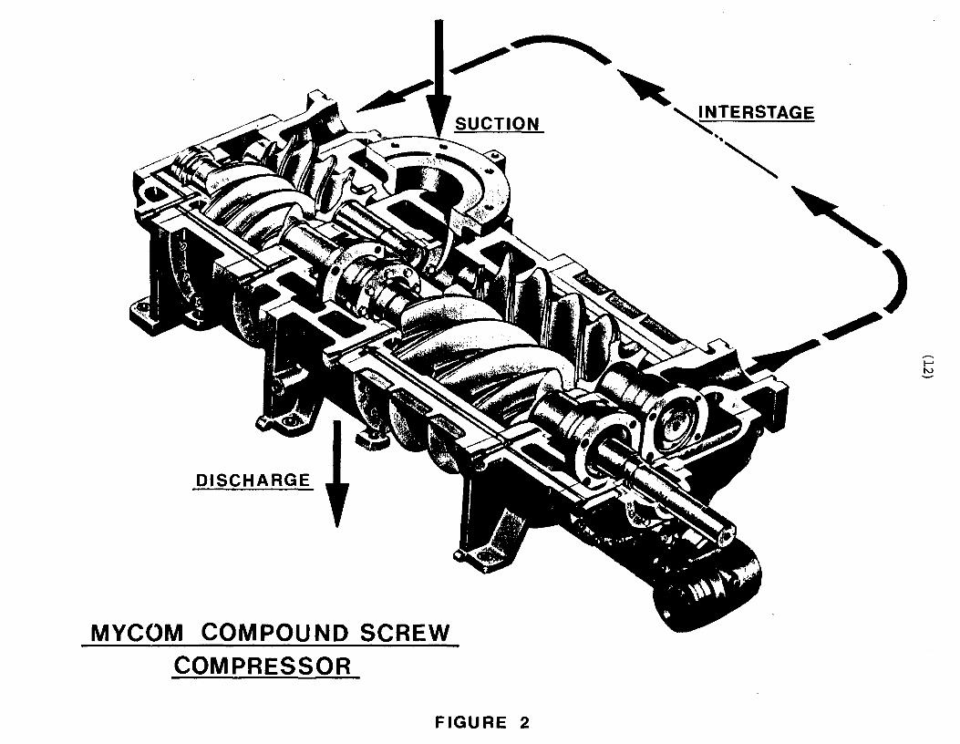
The compressor is a two stage, oil flooded screw compressor utilizing unsymmetrical rotor profiles. A typical machine cross section is shown in Figure 2. The drive rotors are of male configuration and have 4 Jobes each. The driven rotors are of female configuration and have 6 lobes each. The compressor is a positive displacement unit, and with the addition of injected oil in the helium gas stream the normally isentropic compression becomes a polytropic process approaching an isothermal compression. Such a process reduces power requirements and increases the mean time between failures for the unit by operating at lower temperatures.
The compr~ssors were designed to deliver a conservative flow rate of 375 lb/hr (47.2 g/sec) of helium gas from inlet conditions of 1 stm and 70°F to a discharge pressure of 279 psig and 110 F temperature. The theoretical brake horsepower (bhp) for the above flow was 281.5 hp. With 340 bhp delivered, flows of ~ 56 g/sec have been recorded with suction pressure of ~ 1.07 atm. Figure 3 shows Mycom's calculation of the bhp required for different flow capacities. Measurements at Fermilab show that the actual bhp is about 15% higher than the theoretical one for the same conditions. The difference can partially be explained from the effect of the oil injected into the compressor. A 4% bhp reduction was measured when 9 gal/min. of oil was stopped from continuously flowing into the compressor suction. A small fraction of this oil flow is only needed during compressor capacity changes.
The bearing system consists of oil lubricated journal bearings for each rotor. Rotor thrust is maintained at a predetermined value by the action of an integral, oil activated, thrust balance piston. The residual end thrust is absorbed by angular contact ball bearings. The rotation direction of the input shaft is counter-clockwise facing the end of the shaft.
Capacity control is accomplished by an unloader slide valve which moves parallel to the rotor axis and changes the area of the opening in the bottom of the rotor casing. This, in effect, lengthens or shortens the compression zone of the rotor and further acts to return gas to the suction side. Actuation of the slide valves is by hydraulic pressure controlled through solenoid valves. The solenoid valves are

(3)
in turn controlled by signals from position controllers, which receive their signals from pressure transmitters (pneumatic to current) . The unloader indicator is connected to a potentiometer, and the indicator position in percentage is transmitted to the Control Room Console. Figure 4 shows the relationship between the indicator position and the load capacity for the first compressor stage. The unloader slide valve movement is limited by a metal block so that the load capacities are a minimum of 10% for the low stage and 20% for the high stage.
Drive Motor
The motor is connected to the compressor by a doubleflexing disc coupling of the spacer type. The motor is the squirrel cage induction type with open drip-proof enclosure. Existing motors are 350 hp 460 vac 3 phase, 3600 rpm with a service factor of 1.15. With higher suction pressures, 1.1-1.4 atm, the 350 hp motors run in their 1.15 service factor. These motors will be replaced with 400 hp high efficiency motors.
Lube Oil System
The complete oil system consists of all the components necessary to store, circulate, filter, cool and separate the oil which is used as a coolant and lubricant for the compressor. The system operates by pumping the: oil from a storage reservoir at a controlled pressure and rate, cooling and filtering the oil and then injecting the oil into the appropriate control devices, bearings and compressor passages. An oil separation device i~ provided in the reservoir assembly. Oil is stored in a pressurized vessel which serves as an oil reservoir and an oil separator (i.e. for separating oil from the compressed helium stream). An oil pump draws this oil through an oil cooler, a pump suction strainer, and drives it through a 10 micron filter and injects it into the compressor at several locations for lubrication and oil injection. Oil is injected into the helium stream only during the first stage of compression and is discharged from the first stage entrained in the gas stream, and injected into the second stage. After the second stage of compression, the gas oil mixture is delivered to the oil separator where the oil is allowed to settle out into the oil reservoir.
Oil Pump
The oil pump is a screw-configuration design type. The pump is direct-driven by Q 7.5 horsepower, 460vac 60 Hz 1750 rpm motor, and it is rated at 80 GPM flow. The necessary valves, regulators, and controls are provided to accomplish removal of the pump for replacement or maintenance. Because

(4)
of the helium gas in the: compressor oil, the pump shall always be run with a positive suction head. Oil flow losses from the piping oil cooler and strainer upstream of the pump require a pressure of 20 psig minimum in the oil reservoir prior to starting the compressor.
Oil Cooler
Oil cooling is provided by a single shell and tube heat exchanger designed and constructed in accordance with the requirements of TEMA "C". The cooling water is on the tube side, and the oil is on the shell side. The copper-nickel tubes are welded to the tube sheet. The water side is designed for 150 psig maximum working pressure. For the majority of the compressors, the oil coolers are installed upstream of the oil pump and this led to heat exchanger rated for 330 psig in the shell side. For three compressors at C~ the oil coolers were rated for 400 psig because they were installed downstream of the oil pump. For the seven compressors now under fabrication, the oil cooler will be installed on the oil pump discharge. This improved design will prevent oil pump cavitation when starting with low oil reservoir pressure. Maximum pressures on the oil (shell) side are limited by ASME approved relief valves (Refer to Drawing No. 9140-ME-129720). The oil outlet temperature is controlled to the desired value by automatically regulating cooling water flow 0ate with a flow control valve. With l00°F inlet and 107 F outlet cooling water temperatures, 200 GPM of water is required for the compressor system.
Oil Separator
The oil separator is a horizontal vessel that also serves as the reservoir for 80 gallons of oil. Gas delivered by the compressor contains mist. as a result of contact with the lubricating oil. This oil is effectively removed to a level of 2500 ppm by weight, by the action of a demister element, installed in the separator shell an integral part of the reservoir. The oil separator/reservoir vessels are all rated and code stamped for 330 MAWP. An ASME pilot operated relief valve set at 325 psig is installed from the top of the oil separator vessel to protect the compressor system. The discharge of the valve is connected to the 4 inch suction pife. The valve is designed to relief 3.8 times normal compressor capacity with back up pressure up to 150 psig.
Instruments and Controls
Instruments and controls necessary for operation of the compressor system are installed on the skid. Figure 5 shows a typical outline of the instrumentation and control panel mounted on the end of the compressor skid. Manual local operation is possible by switching the capacity

(5)
selector switch to the "MAN" position and selecting "LOAD" or"UNLOAD" as desired by using the selector switches for the low stage and high stage capacity controls. The switches operate solenoid valves which, through hydraulic pressure and pistons,modulate the integral slide valves. The local automatic capacity controls have been disconnected and replaced by the Microprocessor Based Control System. Operation is possible from the Accelerator Main Control Room and the following capabilities are available:
1. Remote compressor starting and stopping
2. Automatic capacity regulation
3. Remote capacity regulation
4. Remote analog and digital readback
5. Remote alarms
Emergency Shutdown
Manual emergency shutdown of the system is accomplished by depressing the "STOP" push button. Automatic shutdown of the system occurs if any of the following system safety switches are activated:
High discharge pressure (300 psig) EPNT-022-H (this will be changed to 320 psig)
High gas discharge temperature (190°F) ETNT-023-H
High oil temperature (140°F) ETNT-071-0
Low oil pressure differential (20 psid) EDPT-074-0
Oil removal system oil level high (3" below filter) ELNT-041-0
Compressor Maintenance
Routine r.taintenance of the system during normal operation consists primarily of monitoring the fluid management system parameters such as filter pressure, oil level and flow rate and monitoring the coffipressor pressures and temperatures. Vibration signature analysis for the motors and compressor body is periodically required. We have a portable vibration analyzer giving a hard copy printout of the vibration spectrum with amplitude and frequency scale values.
Oil and Moisture Removal System
The purification system removes oil mist, oil vapor, water vapor, and particulates from the compressed helium. The units

(6)
are designed with consideration of modularity reliability, and necessary redundancy (i.e. guard purification). Figure 6, shows a block diagram of the oil removal system.
The final configuration of the oil mist removal system is the result of a competative bid to a performance specification. The vendor's offering was proof tested at C~, and test results are included in Figure 7. High gas velocities (>100 ft/min) on the outside of the; filters gave unstable performance. The final vessel design was done at Fermilab using the Monsanto "Mist Eliminator" filter and the space available on the compressor frame. Three identical stages of oil mist were installed with the first two stages removing the oil mist to levels acceptable for cryogenic refrigeration operation. The third stage then provided the above mentioned "necessary redundancy". The first two coalescers are mounted on the compressor frame with automatic solenoid valves returning the oil to the compressor interstage. A portable skid contains a third coalescer which is used as a guard purifier. The skid also contains a charcoal and a molecular seives adsorber followed by a final particle filter.
The charcoal adsorbent vessel is installed to remove the oil vapor from the helium gas. The vessel was designed for a maximum surface velocity of .32 m/min with an upwa1d flow. The gas velocity is conservatively low to prevent any channeling effect and fluidization of the top layer. The normal designed contact time for the gas required to traverse the depth of the activated charcoal bed is 28 sec. From a study made of the best and most economical activated carbon adsorbent, Union Carbide JXC and American Norit Sorbonorit B4 were found to be the leaders. We have purchased and installed both type of carbons. The charcoal vessel is 24" O.D. and - 9" tall. It contains 270 Kg (~600 lbs) of carbon pellets. The carbon, as delivered from the vendor, contains - 2% of moisture. After the carbon is installed in the vessel, the moisture is removed by purging the bed with soo°F nitrogen gas until the nitrogen coming out of the vessel (~375°F) has a dew point of --60°c. The vessel is wrapped with insulating blankets. This charcoal dehydration usually takes about 1.5 days.
The molecular sieves vessel is installed downstream of the charcoal bed. Type 4A molecular sieve is used to adsorb water vapor left in the helium gas. The vessel is 18 inches in diameter and 6 feet high. The 282 lbs. of adsorbent is used to fill the vessel with conical screens on both ends. The flow in the bed is downward with conservatively low velocity. With 20% binder material and with a calculated LUB (equivalent length of unused bed) of 0.8 feet, the useable molecular sieve weight is 181 lbs. From the wa~er adsorption isothermal curves, the 4A molecular sieve at 77 F has an equilibrium loading of 8.8%. This is at 20 atm pressure and water partial pressure of 2.94 x lo-4 psia (1 ppm contamination level). This means that a fresh bed (with 2% residuaY loading) has a capacity of retaining 12.2 lbs of water with < 1 ppm effluent contamination. v

( 7)
Adsorber beds for oil vapor and water vapor removal were sized and designed at Fermilab with adsorbent performan~e data provided by the manufacturers. All vessels for the oil removal system have been built by outside code shops and have been designed, constructed and tested in accord~nce with Section VIII of the latest ASME Code for Unfired Pressure Vessels. The vessels have a U stamp for 350 psi MAWP and are protected with an ASME 350 psig safety relief valve.
The final filter is installed downstream of the adsorbent pellets material to retain any particle of 1 micron and larger. The Dollinger Corporation makes the filter assembly which consists of a 8-5/8 O.D. x 24" high vessel with a single filter element. The gas flow is from the outside to the inside of the filter. The radial fin-pleating design of the filter gives the element collapse pressure of 50 psi.
Purification System Operation and Maintenance
Oil Coalescers
The coalescer filters are permanently installed J.n the vessels and no maintenance is required. The Monsanto filters are built strong, and with the clean gas, they should last a long time. At some unusual compressor operation or every six months, pressure differential readings should be taken across the coalescer vessels with compressor full flow. Normal pressure differential readings are as follows: (refer to Figure 6)
No. 1 Coalescer No. 2 Coalescer No. 3 Coalescer
6P#l = 9-14 inches of water 6P#2 = 2-4 inches of water 6P#3 = 2-3 inches of water
Including the adsorber skid package, the pressure differential is (between valves MV-081-H and MV-089-H) :
6P across purification system = 32-38 inches of water
Oil Drain
The first oil collection is just a 2 inch pipe at the bottc.1m of a "T" fitting branch. Oil mist is separated from the gas by the inertia impaction of the oil on the side of the "T" fitting. Three solenoid valves automatically drain the oil from the pipe and the two coalescer vessels. The solenoid valves are energized by a programmable process controller to open every 15 minutes and stay open for 30 sec. The controller is programmed to open the valves in sequence to minimize gas bypass. Pressure differential flows the oil back to the compressor's interstage pipe. Each solenoid valve has a manual
( 8)
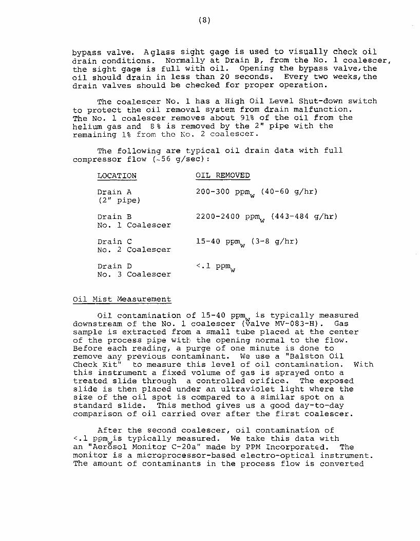
bypass valve. Aglass sight gage is used to visually check oil drain conditions. Normally at Drain B, from the No. 1 coalescer, the sight gage is full with oil. Opening the bypass valve,the oil should drain in less than 20 seconds. Every two weeks 1 the drain valves should be checked for proper operation.
The coalescer No. 1 has a High Oil Level Shut-down switch to protect the oil removal system from drain malfunction. The No. 1 coalescer removes about 91% of the oil from the helium gas and 8% is removed by the 2" pipe with the remaining 1% from the No. 2 coalescer.
The following are typical oil drain data with full compressor flow (~56 g/sec) :
LOCATION
Drain A (2 II pipe)
Drain B No. 1 Coalescer
Drain C No. 2 Coalescer
Drain D No. 3 Coalescer
Oil Mist Measurement
OIL REMOVED
200-300 ppmw (40-60 g/hr)
2200-2400 ppm (443-484 g/hr) w
15-40 ppmw (3-8 g/hr)
<.l ppm w
Oil contamination of 15-40 ppmw is typically measured downstream of the No. 1 coalescer (valve MV-083-H). Gas sample is extracted from a small tube placed at the center of the process pipe with the opening normal to the flow. Before each reading, a purge of one minute is done to remove any previous contaminant. We use a "Balston Oil Check Kit" to measure this level of oil contamination. With this instrument a fixed volume of gas is sprayed onto a treated slide through a controlled orifice. The exposed slide is then placed under an ultraviolet light where the size of the oil spot is compared to a similar spot on a standard slide. This method gives us a good day-to-day comparison of oil carried over after the first coalescer.
After the second coalescer, oil contamination of <.l ppm is typically measured. We take this data with an "Aer~sol Monitor C-20a" made by PPM Incorporat~d. The monitor is a microprocessor-based electro-optical instrument. The amount of contaminants in the process flow is converted

(9)
into micro grams per unit volume (µgs/m3). The helium gas
passes through the center of the sensor which can be installed in line with the process piping. This instrument should only be used for aerosol contamination of <2 ppm to keep the optical apparatus clean from oil mist. The~efore, oil contamination should always be checked with the treated slide first. The range of the C-20a is from 0 to 0.8 ppmw.
Adsorbent Beds
Data for oil vapor adsorption in charcoal beds is scarce. So two vessels (installed at B~) have been built with six ports on the vertical sides to measure the MTZ (Mass Transfer Zone) wave propagation. The MTZ is the band in which adsorption is taking place. As the wave front progresses through the bed, some oil vapor begin to show in the effluent. When the wave front passes out of the bed and the effluent concentration equals the influent value, then "Saturation" capacity has been reached. At this point the carbon bed has to be changed. As a guide in sizing the vessel, Barnebey-Cheney T-430 report gives a table relating superficial contact time vs. the oil removal efficiency for compressed air application. With the designed contact time of 28 sec., oil vapor removal efficiency of 99.85% is given.
With compressor full flow (~56 g/sec), the following are the pressure drops measured across the adsorbent beds:
Charcoal bed 24" diam vessel 4/6 Tyler mesh pellets
Molecular sieve bed 18" diam vessel 1/16" diam. pellets
6P = 3-4 inches of water
6P = 7-8 inches of water
With the relatively low gas velocities in the beds, deterioration of the adsorbents is minimized. Data taking of the pressure drop across the vessels should be every six months.
To measure moisture contamination, we use the Pansmetric Model M2L, Dew Point Probes. With these sensors, -110 C dew points can be measured. The type 4A molecular sieves that we use have been considered the universal product of dehydration of most fluids and gasses. Adsorption isothermal curves are available where the water partial pressure (psia) versus the adsorption capacity (lb. H20/lb mol. sieves) is given for different temperatures. One can calculate the capacity of a bed; however the velocity of the MTZ is mostly experimental. At A~ we have installed one molecular sieve

(10)
vessel with ports on the side to take dew point measurements. Molecular sieves generally behave as physical adsorbents. When water molecules enter the internal sieve structure, they are held (adsorbed) by physical forces of the Van der Waals type. At some point the adsorbents become saturated, and as the water partial pressure inside the sieve exceed the water partial pressure in the helium gas, some of the water will migrate to the gas. Every two weeks, moisture data should be taken upstream and downstream of the molecular sieves vessels. This is very important especially during the first commissioning where we do not have any sub~tantial data to refer to. Our goal is to have < 1 ppm (<-76 C at atm) of moisture effluent. Calibration check of the dew point sensors is very important for the low moisture level that we are working with. For this we have purchased a portable field calibration system to verify the calibration of any hydrometer in use. This apparatus generates precise and repeatable concentrations of wster vapor in a carrier gas stream to an accuracy of + 0.5 C. When the dew point exceeds -7o 0 c (2.5 ppm at atm), the bed should be changed with new molecular sie~es. For our goal to have < 1 ppm of moisture, we require molecular sieves with < 2% resid~al moisture. This is hard to achieve with standard industrial regeneration.
Final Filter
The final filter picks up the dust associated with the adsorbent beds. The filters can be changed by opening an 8 inch flange on the top of the vessel (a new gasket should be used) . Pressure differential data across the vessel should be taken every time new adsorbent beds are filled and also at six months intervals. Typical pressure drops are 2-3 inches of water.

SUCTION PORT --- CONTROL PANEL
DISCHARGE PORT---
COMPRESSOR
· PUMP ' OIL RESERVOIR I -----1
1..-~1_4_~ _____ 68
______ -11•~! SEPARATOR VESSEL 6 PLACES.
i.....~---~------------~122·-----------
l...-'--------------~156±1 ------------------...-i OVERALL
MYCOM COMPRESSOR SKID - SIDE VIEW
FIGURE 1
42
DISCHARGE
MYCOM COMPOUND SCREW COMPRESSOR
FIGURE 2
' ~~TERSTAGE .. ""
-I-' N -

(13)
MYCOM COMPRESSOR 2016C BHP vs CAPACITY
SCREW COMPRESSOR UNLOADING CHARACTERISTICS
' 80
GAS: HELIUM RPM: 3565
160 SUD-M
57 PSIA
294 PSIA.
137°F
200 LUD-L
14.7 PSIA
57 PSIA
70°F
-- : 60 ~·
a. :c
I
I '
co 40 HlbH STAGE
20
20 40 50 60 , I
dAPACITY . , : I
80 100 {491 lb/hr)
(61.8 G/sec)
'
I~ I !
FIGURE 3

-- : - L...:.___:
~-+---
. 'l; ::::
: : ! I . !·'
~ ' ' I ,, •!
l' ! '
(14)
11 i l l t ! 1 ~! i I If h r r ~ = f ~ r L ~~ffiH-++r+++ 11
r-H-rnH+r+++H-1-tt1+++++1-H-1 r~1 ->-+-.-! t+41 rw i rn !Ht 1 iii :C'\ 1t; ~:!~ .,H p11 ~rJJ. ~ ~ .t- ti-U H [r 1 Hft fiJI :l ! i ,-,:-r rt:;;;: r:~ ~~;: :~;t ,·:it . ' • • • t ' I I I ' ! I ' ' • 'I Ill u . •. 1·... 1 i • ! t I f I I ; \ I 1. I I l 1 '. ! I ' ' I ' ' ' : ; I ' ' ' : : ; : : i : : ~ : i : t'
: : : ; 1 ; r . ; I ( I r ; f: ; : : : ·1
; : t : : ; : r 1 ; •1 t >
1· I ·
1 : t .
11 :
11 1 ir l : : : : : 1
11 't ' ' · i 1 .. .. .. • ! " · · .. ; ' 1 !
"" t!i •Ill I It d:, I, I it!\ it!\ I Jj ! j I I I;; ilii lf1 t;; lt;; ;:;~~'I tolo 1~:· ;:;l '.:t!t i, :i;f .1 .... 1. 1 • ., I
LOAD CAPACITY VS INDICATOR POSITION :::: ~: .. : 1"
1 i 1
-~~------------------------------------------------------------...-.--;..-.... -.-...:...~;~:~:::..t-:..:~:~~:i·~~:~!~:u.LUJli 100 100 "" ''" :::1 ,i ! : ; : ' : '.: : ii f
.....
- ;.....;.- ...... ..+<~>+-__._++4......_.
95 99.85 •: ''" ;; i ;;:! :: : ' • 1 T : ~ : : : : ~ ! ~ t !
90 99.33 8 5 98.39 80 96.81 70 90.49 60 77.59 50 60.70 40 43.96'
' 30 29.01
1::: '1 ••
'ill •t+I 1.11
' "' f: i ; ~- ~-----· ·-+--+---___,_:_: ,_· :++-i !_.__,:
t! •. • .••
r,-,-.~. ~-+~;:~:-:1--·-+-'.~;·-·-1---·~·4' ~:.J_:_ i ; : ; " . l ; ; i : ~ i ; ; ; f : :
:!:.
.. ,. :::: ::; : !I 1· I 1 1,
:.,+ ! : ~ : . ~ . ' J •••
;: :: '' •t 'J,,
:111
'' 11 t•+;
.:!
l••' . . . .. j,'.
--~
... .,,. '1··t 111t" "11·1.111 '.·.··r 'I'' I . :. ·. :' :.. I II : I ' i ! : : I I' ' 1 • : I ' ;_ : ! I ! i,, 11 j I ' ! I ' ; : Ii : I ' : -·-- :1 1;11 .... I 1 ;I 11: ·', I· ti.11111lfi!1:1: ::r: 1::: · ::;! ............ .
, '1:: :11 i,,, :,1 .. 1'::. '1·1,1·:1 111 r11·1 :I: r 11111 r'11:1' '1!''1.:, '11111 •111 i1:: ·:·: .1, .... ._,.__ ~--._. ___ .__ : i ; ~ l : I ; ! : ( I ' + I I : ~ !- I l i t t t ' l : f I I ! i ; I ! f f ! ! ! : 1 ~ l l ! : ' '. i : : I : :
FIGURE 4

'"~""' :~· 0 0 n 0 lwANIFOLOi jcPS:OISCHI
/LOADIN6 oiF y v n jsvSTEM OISCHl\/lsEPARATOR I ~~.::=.._::::.:::_~U~N~L~OA~D~INNCG/ Jr.-:iiA~C--,;;;,.--__:~~~- - _ - I LOADING OFF I ~ ® rlii\\ --1 """~ 1-u-I•~• I
l HIGH PRESS CONTROLLER
!AUTO MANUAtj ~ iLOCALj IREMOTEJ
0
[8] I HOUR METER I
MVCOM COMPRESSOR INSTRUMENTATION PANEL FIGURE 5

TO 3HHIGH
PRESSURE MANIFOLD
MV-089-H
a: w t-
_J_j
a: <! -.Jw =>> Ow w_J(/)
0 ~
<(~
~~ 088-H
<!PPM TEST & C-20 TEST PORT L
.3·100 PPM TEST
lc.p'"2 ;..,. v 083 H ;-AP"I ""]
MV-087-H
_J a: <(W QCll (.)a: a:o <( (/)
IO (.) <(
a: w ,__ _ ___.u (/)
~Wr0 . -1'"
,__ _ ___.<( 0 (.)
GUARD PURIFIER
DRAIN D
OIL MANIFOLD
HIGH OIL LEVEL SHUT-DOWN
HELIUM GAS PURIFICATION SYSTEM
FIGURE 6
TO INTERSTAGE
FROM COMPRESSOR
_.-...
.......
°' -

FILTER VESSEL He GAS ELEMENTS SIZE FLOW
15 elements 8 in 41. 7 2 3/4 "OD x 9 5/8" LG Sch 40 ACFM
18 elements 12 in 41. 7 2 3/4 "OD x 9 5/8" LG Sch 40 ACFM
l elements 14 in 41. 7 10 1/2 "OD x 24" LG Sch 40 ACFM
l element 18 in 41. 7 12 "OD x 42" LG Sch 40 ACFM
(1) Start-up after overnight shut-down (2) Steady state after 16 hr of running
OIL MIST COALESCING TEST RESULTS
CRITICAL VELOCITY VELOCITY THROUGH ON FILTER'S FILTER SIDE
1. 6 ft/min 296 ft/min
1.4 ft/min 100 ft/min
17.7 ft/min At exit pipe 677 ft/min
7.5 ft/min 48 ft/min
(3) Oil contamination 2500-3000 ppm from compressor
FIGURE 7
(3) AVERAGE AVERAGE PRESSURE OIL CONT. OIL CONT. DROP
AFTER AFTER ACROSS 1st. STG. 2nd. STG. VESSELS
(1) 250 ppm (1) 5 ppm 1st 1. 7 psi (2) 4\3 ppm (2) .020 ppm 2nd 1. 1 psi
(1) 30 ppm (1) .020 ppm 1st 1. 7 psi (2) 43 ppm (2) .015 ppm 2nd 1.1 psi
(1) 275 ppm (l) 8 ppm 1st < .2 psi (2) 275 ppm (2) 8 ppm 2nd < .2 psi
(1) 40 ppm (1) .024 ppm 1st .18 psi (2) 40 ppm (2) .024 ppm 2nd .12 psi

![dk Fermi National Accelerator Laboratorylss.fnal.gov/archive/tm/TM-1600.pdfThe new bunch spreader project [1],[2] for the Main Ring is in progress. The project increases the longitudinal](https://static.documents.pub/doc/80x56/5f4fa9e644d5cc5ccb56818f/dk-fermi-national-accelerator-the-new-bunch-spreader-project-12-for-the-main.jpg)


