0 Ferroelectric Materials for Small-Scale Energy Harvesting Devices and Green Energy Products Mickaël Lallart and Daniel Guyomar LGEF, INSA-Lyon France 1. Introduction Portable electronic devices and autonomous systems experienced a strong development over the last few years, thanks to progresses in microelectronics and ultralow-power circuits, as well as because of an increasing demand in autonomous and “left-behind” sensors from various industrial fields (for instance aeronautic, civil engineering, biomedical engineering, home automation). Until now, such devices have been powered using primary batteries. However, such a solution is often inadequate as batteries raise maintenance issues because of their limited lifespan (typically one year under normal conditions - Roundy, Wright and Rabaey (2003)) and complex recycling process (leading to environmental problems). In order to tackle these drawbacks, many efforts have been placed over the last decade on systems able to harvest electrical energy from their close environment (Krikke, 2005; Paradiso and Starner, 2005). Many sources are available for power scavenging, such as solar, magnetic, mechanical (vibrations) or thermal (Hudak and Amatucci, 2008). In order to power up small-scale devices, a particular attention has been placed on the last two sources (Anton and Sodano, 2007; Beeby, Tudor and White, 2006; Jia and Liu, 2009; Vullers et al., 2009), as they are commonly available in many environments and because the conversion materials can be easily integrated within the host structure. The purpose of this chapter is to give a comprehensive view and analysis of small-scale energy harvesting systems using ferroelectric materials, with a special focus on piezoelectric and pyroelectric devices for vibration and thermal energy scavenging systems, respectively. As the energy that can be provided from microgenerators is still limited to the range of tens of microwatts to a few milliwatts, a careful attention has to be placed on the design of the harvester. In particular, backward couplings that may occur between each conversion and energy transfer stages require a global optimization rather than an individual design of each block. The chapter is organized as follows. Section 2 aims at presenting energy sources and conversion materials that will be considered in this study, as well as basic models for the considered conversion devices. Then section 3 will give a general view of a typical microgenerator, emphasizing the energy conversion chain and issues for optimizing the energy flow. Sections 4 and 5 will focus on two important energy conversion stages (energy conversion and extraction), highlighting general optimization possibilities to get an efficient energy harvester. Implementation issues for realistic applications will then be discussed in 5 www.intechopen.com
Transcript
0
Ferroelectric Materials for Small-Scale EnergyHarvesting Devices and Green Energy Products
Mickaël Lallart and Daniel GuyomarLGEF, INSA-Lyon
France
1. Introduction
Portable electronic devices and autonomous systems experienced a strong development overthe last few years, thanks to progresses in microelectronics and ultralow-power circuits, aswell as because of an increasing demand in autonomous and “left-behind” sensors fromvarious industrial fields (for instance aeronautic, civil engineering, biomedical engineering,home automation). Until now, such devices have been powered using primary batteries.However, such a solution is often inadequate as batteries raise maintenance issues becauseof their limited lifespan (typically one year under normal conditions - Roundy, Wright andRabaey (2003)) and complex recycling process (leading to environmental problems). In orderto tackle these drawbacks, many efforts have been placed over the last decade on systems ableto harvest electrical energy from their close environment (Krikke, 2005; Paradiso and Starner,2005). Many sources are available for power scavenging, such as solar, magnetic, mechanical(vibrations) or thermal (Hudak and Amatucci, 2008). In order to power up small-scale devices,a particular attention has been placed on the last two sources (Anton and Sodano, 2007; Beeby,Tudor and White, 2006; Jia and Liu, 2009; Vullers et al., 2009), as they are commonly availablein many environments and because the conversion materials can be easily integrated withinthe host structure.The purpose of this chapter is to give a comprehensive view and analysis of small-scale energyharvesting systems using ferroelectric materials, with a special focus on piezoelectric andpyroelectric devices for vibration and thermal energy scavenging systems, respectively. Asthe energy that can be provided from microgenerators is still limited to the range of tensof microwatts to a few milliwatts, a careful attention has to be placed on the design of theharvester. In particular, backward couplings that may occur between each conversion andenergy transfer stages require a global optimization rather than an individual design of eachblock.The chapter is organized as follows. Section 2 aims at presenting energy sources andconversion materials that will be considered in this study, as well as basic models forthe considered conversion devices. Then section 3 will give a general view of a typicalmicrogenerator, emphasizing the energy conversion chain and issues for optimizing theenergy flow. Sections 4 and 5 will focus on two important energy conversion stages (energyconversion and extraction), highlighting general optimization possibilities to get an efficientenergy harvester. Implementation issues for realistic applications will then be discussed in
5
www.intechopen.com
2 Feroelectrics Vol. IV: Applications
Section 6. Section 7 will present some application examples to self-powered systems. Section 8will finally briefly conclude the chapter.
2. Energy sources and modeling
Two conversion effects of ferroelectric materials will be considered through this chapter:piezoelectricity, which consists of converting input mechanical energy into electricity, andpyroelectricity, allowing harvesting energy from temperature variations. Therefore, twoenergy sources will be considered in this study: mechanical energy and thermal energy. Theconstitutive equations for piezoelectric materials are given by:
{
dT = cEdS − etdE
dD = ǫSdE + edS, (1)
where D, E, S and T respectively refer to electric displacement, electric field, strain and stresstensors. cE, e and ǫS stand for elastic rigidity of the material, piezoelectric coefficient andelectric permittivity under constant strain. Finally, d and t represent the differentiation andtranspose operators respectively. In the case of pyroelectric devices, the equations yield:
{
dσ = pdE + c dθθ0
dD = ǫθdE + pdθ, (2)
with θ and θ0 the temperature and mean temperature, σ the entropy of the system, p thepyroelectric coefficient, c the heat capacitance and ǫθ the electric permittivity under constanttemperature.This allows the derivation of energy densities that may be typically obtained. Table 1 givesthe comparison of the electrostatic energy density of the two devices for a typical solicitation.It can be seen that the two materials feature relatively close energy density values. Thiscan be explained by the fact that, although piezoelectric coupling is generally much higherthan pyroelectric coupling, the input mechanical energy is usually much less than the energygenerated by temperature variation. Therefore, the global energy, given by the productof input energy by conversion abilities, is similar for the two materials. Nevertheless, asmechanical frequencies are typically much higher than thermal frequencies, the output powerof piezoelectric-based microgenerators is greater than devices using pyroelectric materials(Guyomar et al., 2009; Lallart, 2010a).Moreover, because of their higher coupling coefficients, extracting energy from piezoelectricelements can affect the mechanical behavior of the system, while the coupling of pyroelectricdevices is small enough to neglect the backward coupling (i.e., only the second equation ofEq. (2) can be taken into account).The model of a global structure can also be obtained from the local constitutive equationsEqs. (1) and (2). In the case of a piezoelectric element (possibly bonded on a structure under
Electrostatic energy density (Wel)piezo = 1.4 μJ.cm−3 (Wel)pyro = 2.7 μJ.cm−3
Table 1. Energy densities for typical piezoelectric and pyroelectric materials
96 Ferroelectrics - Applications
www.intechopen.com
Ferroelectric Materials for Small-Scale Energy Harvesting Devices and Green Energy Products 3
flexural solicitation), it can be shown that the system may be modeled around one of itsresonance frequencies by an electromechanically coupled spring-mass-damper system (Badelet al., 2007; Erturk and Inman, 2008):
{
Mu + Cu + KE = F − αVI = αuu − C0V
, (3)
where u, F, V and I refer to the displacement (at a particular position of the structure), appliedforce, piezovoltage and current flowing out of the active material. M, C and KE denote thedynamic mass, structural damping coefficient and short-circuit stiffness of the system, whileαu and C0 are given as the force factor and clamped capacitance of the piezoelectric insert.In the case of pyroelectric energy harvesting, it has previously been stated that the lowcoupling coefficient permits neglecting the backward coupling. Hence, only the electricalequation is necessary, leading to the macroscopic equation (Guyomar et al., 2009; Lallart,2010a):
I = αθ θ − C0V, (4)
with αθ the pyroelectric factor.
3. Overview of a microgenerator
The principles of an energy harvester lie in several energy conversion and transfer stages toconvert the input energy into electrical energy supplied to a load. Basically, four intermediatestages appear between the energy source and the device to power up (Figure 1):
1. Conversion of the raw input energy into effective energy that can be transferred to theactive material.
2. Conversion of the energy available in the material into electrical energy.
3. Extraction of the electrical energy available on the material.
4. Storage of the extracted energy.
Fig. 1. General energy harvesting chain
97Ferroelectric Materials for Small-Scale Energy Harvesting Devices and Green Energy Products
www.intechopen.com
4 Feroelectrics Vol. IV: Applications
However, the energy transfer is not unidirectional. There exist backward couplings that alterthe behavior of the previous stage (Figure 1). Therefore, because of these backward couplings,the design of an efficient energy harvester should take the whole system into account. Inparticular, three main issues have to be considered to dispose of an effective microgenerator:
• Maximization of the energy that enters into the host structure.
• Enhancement of the conversion abilities of the material.
• Optimization of the energy transfer.
3.1 Piezoelectric system
When considering vibration energy harvesting using the piezoelectric effect, two cases can beconsidered. Either the piezoelectric element is directly bonded on the structure (Figure 2(a)),yielding an open-circuit piezovoltage that is a direct image of the strain and stress withinthe host structure, or an additional mechanical system is used (Figure 2(b)), allowing aneasier maintenance but requiring a fine tuning of the resonance frequency so that it matchesone of the mode of the host structure1. In all the cases however, the system is operatingunder dynamic mode in order to dispose of a significant amount of mechanical energy(Keawboonchuay and Engel, 2003).In the case of direct coupling the energy provided by the input force is first convertedinto mechanical energy through the host structure, and then to electrostatic energy bythe piezoelectric element, while when using indirect coupling an additional mechanical tomechanical energy conversion stage appears (a part of the energy in the host structure istransferred to the additional mechanical system).The previous design criteria when using piezo-based microgenerators therefore consist of:
• Properly positioning the piezoelement near maximum strain/stress locations (for directcoupling) or maximum acceleration areas (for indirect coupling) and adapting theadditional structure to the host structure in the case of seismic coupling.
• Using piezoelectric elements featuring high coupling coefficients and/or using artificialenhancement of the global coupling factor.
• Adapting the load seen by the piezoelectric element.
Obviously, the interdependence of the conversion stages necessitates a global approach ratherthan an individual optimization. A typical example is the damping effect generated bythe harvesting process (Lesieutre, Ottman and Hofmann, 2003): as a significant part of themechanical energy is converted into electricity, the former decreases, limiting the vibrationsof the structure and thus the output electrical power.
(a) Direct coupling (b) Indirect (seismic) coupling
Fig. 2. Typical configurations for vibration energy harvesting using piezoelectric elements
1 In the case of seismic coupling multimodal energy harvesting is therefore delicate.
98 Ferroelectrics - Applications
www.intechopen.com
Ferroelectric Materials for Small-Scale Energy Harvesting Devices and Green Energy Products 5
Generally, the structure optimization consists of allowing a large amount of energy to enterin the piezoelectric element (which can be obtained by using a proper geometry - Zhu, Tudorand Beeby (2010)) and ensuring a wide frequency range operation, hence allowing energyentering whatever the force frequency is. This can be achieved by using variable resonancefrequency (Challa et al., 2008; Lallart, Anton and Inman, 2010b) or using nonlinear structures(Andò et al., 2010; Blystad and Halvorsen, 2010a; Erturk, Hoffmann and Inman, 2009; Solimanet al., 2008). Another commonly adopted solution is to use several cantilevers with differentlengths (Shahruz, 2006), which however decreases the power density. The optimization of thelast two items will be exposed in Sections 4 and 5.
3.2 Pyroelectric system
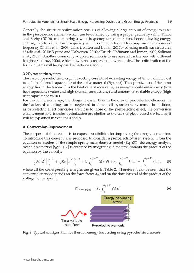
The case of pyroelectric energy harvesting consists of extracting energy of time-variable heattrough the thermal capacitance of the active material (Figure 3). The optimization of the inputenergy lies in the trade-off in the heat capacitance value, as energy should enter easily (lowheat capacitance value and high thermal conductivity) and amount of available energy (highheat capacitance value).For the conversion stage, the design is easier than in the case of piezoelectric elements, asthe backward coupling can be neglected in almost all pyroelectric systems. In addition,as pyroelectric effect principles are close to those of the piezoelectric effect, the conversionenhancement and transfer optimization are similar to the case of piezo-based devices, as itwill be explained in Sections 4 and 5.
4. Conversion improvement
The purpose of this section is to expose possibilities for improving the energy conversion.To introduce this concept, it is proposed to consider a piezoelectric-based system. From theequation of motion of the simple spring-mass-damper model (Eq. (3)), the energy analysisover a time period [t0; t0 + T] is obtained by integrating in the time-domain the product of theequation by the velocity:
1
2M
[
u2]t0+T
t0
+1
2KE
[
u2]t0+T
t0
+ C∫ t0+T
t0
(u)2 dt + αu
∫ t0+T
t0
Vudt =∫ t0+T
t0
Fudt, (5)
where all the corresponding energies are given in Table 2. Therefore it can be seen that theconverted energy depends on the force factor αu and on the time integral of the product of thevoltage by the speed:
Wconv|piezo = αu
∫ t0+T
t0
Vudt. (6)
Fig. 3. Typical configuration for thermal energy harvesting using pyroelectric elements
99Ferroelectric Materials for Small-Scale Energy Harvesting Devices and Green Energy Products
www.intechopen.com
6 Feroelectrics Vol. IV: Applications
Term Meaning12 M
[
u2]t0+T
t0Kinetic energy
12 KE
[
u2]t0+T
t0Potential energy
C∫ t0+T
t0(u)2 dt Dissipated energy
αu∫ t0+T
t0Vudt Converted energy
∫ t0+Tt0
Fudt Provided energy
Table 2. Definition of the energies in the case of piezoelectric energy harvesting
Such an analysis can obviously be applied to pyroelectric conversion, yielding the amount ofconverted energy:
Wconv|pyro = αθ
∫ t0+T
t0
V θdt (7)
Hence, in order to enhance the conversion abilities of the system, three ways can be explored:
• Increase αu (for vibration energy harvesting) or αθ (for thermal energy harvesting).
• Increase the voltage.
• Decrease the time shift between voltage and speed (or temperature variation rate).
Usually, the first point corresponds to the use of piezoelectric materials with higher intrinsiccoupling coefficient (Rakbamrung et al., 2010). This has been done recently through the use ofsingle crystal devices (Khodayari et al., 2009; Park and Hackenberger, 2002; Sun et al., 2009),which typically allows increasing the harvested power by a factor of 20 (Badel et al., 2006).However, single crystals are difficult to obtain, and no industrial process has been achieved,compromising the design of low-cost microgenerators using such materials.In order to enhance the harvesting abilities, a nonlinear approach has been proposed thatallows an artificial increase of the global electromechanical coupling coefficient (Guyomar etal., 2005; Lefeuvre et al., 2006; Makihara, Onoda and Miyakawa, 2006; Qiu et al., 2009; Shu,Lien and Wu, 2007). This process consists of quickly inverting the piezoelectric voltage whenthe displacement or temperature reaches a maximum or a minimum value (or equivalentlywhen the velocity cancels), as shown in Figure 4. Thanks to the dielectric behavior ofpiezoelectric and pyroelectric materials, the voltage is continuous. Hence, the inversionprocess allows a cumulative voltage increase effect, as well as an additional piecewise constantvoltage that is proportional to the sign of the velocity, allowing a magnification of the energyconversion using both the voltage increase and the reduction of the time shift betweenvoltage and velocity. Practically, the inversion of the voltage is obtained by intermittentlyconnecting the active material to an inductor L (Figure 5), shaping a resonant network whichpermits the voltage inversion if the switch SW is open for half an electrical oscillation period.Nevertheless, the losses in this switching circuit lead to an imperfect inversion characterizedby the inversion factor γ (corresponding to the ratio between absolute voltages after andbefore the inversion), which is comprised between 0 (no inversion - voltage cancellation) and1 (perfect inversion).In the framework of energy harvesting, the switching element can be placed either in parallelor in series with the classical energy harvesting circuit (which consists of connecting thematerial to a diode rectifier bridge and a smoothing capacitor Cs as shown in Figure 6(a)),respectively leading to the principles of the parallel Synchronized Switch Harvesting on Inductor
100 Ferroelectrics - Applications
www.intechopen.com
Ferroelectric Materials for Small-Scale Energy Harvesting Devices and Green Energy Products 7
Fig. 4. Nonlinear treatment principles
Fig. 5. Practical implementation of the voltage inversion technique
(parallel SSHI - Figure 6(b) - Guyomar et al. (2005)) and series Synchronized Switch Harvesting onInductor (series SSHI - Figure 6(c) - Lefeuvre et al. (2006); Taylor et al. (2001)). Such an approachtypically allows a gain of 10 using classical components compared to the classical techniquewhen considering constant displacement magnitude. Harvested energies as a function of thesystems parameters (with f0 the vibration frequency, XM the displacement or temperaturevariation magnitude and RL the equivalent connected load) are listed in Table 3.However, backward coupling influences the mechanical behavior of the host structure (moreparticularly by introducing a damping effect) when using piezoelectric energy harvestingat the resonance frequency. In this case, it is possible to get the displacement magnitudeuM from the mechanical energy analysis of the system, leading to the normalized harvested
(a) Classical
(b) Parallel SSHI (c) Series SSHI
Fig. 6. Energy harvesting circuits
101Ferroelectric Materials for Small-Scale Energy Harvesting Devices and Green Energy Products
www.intechopen.com
8 Feroelectrics Vol. IV: Applications
Technique Harvested energy Maximal harvested energy Gain (γ = 0.8)
Standard(4α f0)
2RL
(1+4RLC0 f0)2 XM
2 α2
C0f0XM
2 −
Parallel SSHI(4α f0)
2RL
[1+2(1−γ)RLC0 f0]2 XM
2 21−γ
α2
C0f0XM
2 10
Series SSHI[4(1+γ)α f0]
2RL
[(1−γ)+4(1+γ)RLC0 f0]2 XM
2 1−γ1−γ
α2
C0f0XM
2 9
Table 3. Harvested energies for classical and SSHI techniques and gain under constantdisplacement magnitude
powers depicted in Figure 7. To make this chart as independent as possible from the systemparameters, the power has been normalized with respect to the maximal harvested power inthe standard case when taking into account the damping effect:
Plim =FM
2
8C, (8)
with FM the driving force magnitude. The x-axis of Figure 7 corresponds to the figure of meritgiven by the product of the squared global coupling coefficient k2 (reflecting the amount ofenergy that can be converted) by the mechanical quality factor QM (giving an image of theeffective available energy). This figure shows that the standard and SSHI techniques featurethe same power limit, but the nonlinear approaches permit harvesting the same amount ofenergy than the classical scheme for much lower values of k2QM, meaning that much lessvolume of active materials is required. Figure 7 also shows that the series SSHI performanceis very close to the parallel SSHI. It can be noted that these nonlinear approaches also permitincreasing the bandwidth of the microgenerator (Lallart et al., 2010c). Losses in the inductancethat limit the power increase can also be controlled using proper approaches, such as smootherinversion (Lallart et al., 2010d), PWM actuation that insures a perfect inversion2 (Liu et al.,2009) or by ensuring that the inversion losses are always less than the converted energy overa given time period (Guyomar and Lallart, 2011).Finally, another way to enhance the conversion abilities is to consider a bidirectional energyflow from the source to the storage stage (Lallart and Guyomar, 2010e). This approach permitsbeneficiating of a particular “energy resonance” effect as the converted energy equals the
Fig. 7. Normalized harvested powers under constant force magnitude at the resonancefrequency
2 In this case, driving losses may however compromise the energy balance.
102 Ferroelectrics - Applications
www.intechopen.com
Ferroelectric Materials for Small-Scale Energy Harvesting Devices and Green Energy Products 9
converted energy without providing initial energy (from the storage stage) plus twice thecross-product of the initial voltage V0 times the voltage generated by the active material:
Wconv|bidir =1
2C0
(
α
C0XM + V0
)2
−1
2C0V0
2 =1
2
[
α2
C0XM
2 + 2αV0XM
]
. (9)
Hence, as the harvested energy increases, the initial provided energy during the beginningof a new cycle increases as well, allowing harvesting more energy, and therefore closing the“energy resonance” loop. This approach permits a typical harvested energy gain up to 40under constant displacement magnitude (or constant temperature variation magnitude) aswell as bypassing the power limit when considering the damping effect.It can also be noticed that instead of adding external nonlinearities, Guyomar, Pruvost andSebald (2008); Khodayari et al. (2009); Zhu et al. (2009) have shown that the energy harvestingperformance may be also enhanced by using the intrinsic nonlinear behaviors of pyroelectricmaterials, such as ferroelectric↔ferroelectric or ferroelectric↔paraelectric phase transitions.
5. Energy transfer optimization
The next stage in the energy conversion chain lies in the energy transfer from the activematerial to the storage stage. As the amount of energy provided to the electronic device mayalter the energy conversion process (which can be seen from the load-dependent powers inTable 3 and in Figure 8), additional interfaces have to be included so that the energy extractedfrom the active material is maximum. This section proposes to expose two possibilities toensure a harvested energy independent from the connected load by:
• Ensuring that the active material sees the optimal load.
• Decoupling the extraction and storage stage through a nonlinear approach.
The simplest way for ensuring that the load seen by the piezoelectric or pyroelectric materialequals the optimal one that maximizes the harvested power consists of adding a converterbetween the active element and the extraction stage (Han et al., 2004; Lallart and Inman,
Fig. 8. Normalized harvested powers under constant displacement magnitude (or constanttemperature variation magnitude) as a function of the load (normalized with respect to theoptimal load in the standard case)
103Ferroelectric Materials for Small-Scale Energy Harvesting Devices and Green Energy Products
www.intechopen.com
10 Feroelectrics Vol. IV: Applications
2010f; Lefeuvre et al., 2007a; Ottman et al., 2002; Ottman, Hofmann and Lesieutre, 2003).The converter should operate in discontinuous mode in order to present a constant (oralmost constant) impedance to the piezoelectric element. Usually, the converter parameter(inductance L, switching frequency fsw and duty cycle δ) should also be tuned so that itsinput impedance is close to the optimal load that maximizes the extracted energy (Table 4)3,although an automatic detection of the optimal operating point can be done (Lallart andInman, 2010f; Ottman et al., 2002).Another approach for ensuring a harvested energy independent from the load consists ofslightly modifying the previously exposed nonlinear techniques. In particular, if the switchingtime period is reduced so that it stops when the voltage across the active material is zero,all the electrostatic energy available on the material is transferred to the inductance (undermagnetic form). If this energy can then be transferred to the load, there would not beany direct connection between the load and the piezoelectric or pyroelectric material, thusallowing a decoupling between the energy extraction stage and the energy storage stage.Such a technique, called Synchronous Electric Charge Extraction (Lefeuvre et al., 2005; 2006),is depicted in Figure 9. The SECE approach also permits an enhancement of the conversionthanks to a voltage increase and a reduction of the time shift between voltage and velocity, andallows a typical energy gain of 3.5 compared to the maximal harvested energy in the standardcase under constant displacement magnitude.Nevertheless, the SECE techniques does not allow controlling the trade-off between extractedenergy and conversion improvement, as all the energy on the active material is extracted. Theprinciples of the technique may be enhanced by combining the series SSHI approach with theSECE, leading to the DSSH technique (Lallart et al., 2008a). This scheme, depicted in Figure 10,consists in first extracting a part of the electrostatic energy on the piezoelectric or pyroelectricmaterial on an intermediate capacitor Cint, while the remaining energy is used to performthe voltage inversion leading to the conversion magnification. Then the energy available onthe intermediate capacitor is transferred to the load in the same way than the SECE. Hence,through the ratio between the active element capacitance and intermediate capacitance, it ispossible to finely control the trade-off between extracted energy and conversion enhancement,allowing a typical harvested energy 7.5 higher than the maximal harvested energy in the
Type Impedance Efficiency
Step-down (Ottman, Hofmann and Lesieutre, 2003)(
2L fsw
δ2
)
(
1
1−VoutVin
)
65%
Buck-boost (Lefeuvre et al., 2007a)(
2L fsw
δ2
)
75%
Table 4. Impedance matching systems (Vout and Vin refer to output and input voltages)
Fig. 9. SECE technique
3 As the optimal load depends on the frequency, broadband energy harvesting is quite delicate for thesearchitectures.
104 Ferroelectrics - Applications
www.intechopen.com
Ferroelectric Materials for Small-Scale Energy Harvesting Devices and Green Energy Products 11
Fig. 10. DSSH technique
standard case under constant displacement magnitude or constant temperature variationmagnitude and independent from the connected load. The SECE and DSSH techniques havealso the advantage of being able to harvest energy even for low load values, while in the caseof low frequency (typical for temperature variation), the optimal load for the standard andSSHI approaches would be very large.When taking into account the damping effect caused by the backward coupling in the case ofmechanical energy harvesting using piezoelectric principles, the harvested energy using theSECE and DSSH techniques is given in Table 5 and depicted in Figure 11.Figure 11 shows the effectiveness of the techniques for allowing a significant power outputeven for low values of the figure of merit k2QM, especially for the DSSH approach, whichpermits the same power output than the standard technique with 10 times less activematerials. Contrarily to the SECE technique, the DSSH does not present a decreasingpower for large values of k2QM as the intermediate capacitor also permits controllingthe trade-off between extracted energy and damping effect (or equivalently the backwardcoupling between energy conversion stage and host structure). It can be noted that, due tothe losses in the inductance during the energy transfer process, the power limit is decreased.
Technique Harvested energy
SECE γC2π
k2QM
(1+ 4π k2QM)
2FM
2
C
DSSH4γC
2πk2QM(1−γ)2
(π(1−γ)+4k2QM(1+γ))2FM
2
C for k2QM ≤ 4π
1−γ1+γ
γCFM
2
8C for k2QM ≥ 4π
1−γ1+γ
Table 5. Harvested energies for SECE and DSSH techniques under constant force magnitude(γC refers to the energy transfer efficiency)
Fig. 11. Harvested energy for the SECE and DSSH techniques (γC = 0.9)
4 for the optimal intermediate capacitance value
105Ferroelectric Materials for Small-Scale Energy Harvesting Devices and Green Energy Products
www.intechopen.com
12 Feroelectrics Vol. IV: Applications
However, this statement has to be weighted by the fact that classical and SSHI approachesrequire load adaptation stages, whose effectiveness is usually less than 80%. Hence, thepower limit of the SECE and DSSH schemes is similar to the one obtained with the othertechniques featuring load adaptation stages. Such a statement also applies for constantvibration magnitude or constant temperature variation magnitude case. Finally, it can benoted that the power transfer from the intermediate capacitor to the load can also be controlledby fixing a voltage threshold value, leading to the concept of Enhanced Synchronized SwitchHarvesting (ESSH) described by Shen et al. (2010).
6. Implementation considerations
Now the general principles of energy harvesting exposed, it is proposed in this section todiscuss about their implementation for the design of realistic self-powered devices.The first issue that may arise for the use of nonlinear techniques is the control of the switchingdevice. Actually, the minimum and maximum detection can be done by comparing thevoltage across the active material with its delayed version. The maximum is then detectedwhen the delayed signal is greater than the original one (Lallart et al., 2008b; Liang and Liao,2009; Qiu et al., 2009; Richard, Guyomar and Lefeuvre, 2007). The self-powered autonomousswitching device based on this principles therefore consumes very little power, typicallyless than 5% than the electrostatic energy available on the ferroelectric material, thereforenot compromising the energy harvesting gain. The implementation of the self-poweredswitch, depicted in Figure 12, also shows that only typical electronic components are required,allowing an easy integration of the device.Another point of interest when designing realistic energy harvesters is the incomingsolicitation. While sine excitation is usually considered for theoretical analysis, realisticsystems would be more likely subjected to random input (Blystad, Halvorsen and Husa,2010b; Halvorsen, 2008). Although very few studies addressed this problem in the case ofnonlinear energy harvesting (Badel et al., 2005; Lallart, Inman and Guyomar, 2010g; Lefeuvreet al., 2007b), it can be stated that load independent techniques (SECE, DSSH and ESSH) wouldbe more suitable under such circumstance, as the optimal load is frequency-dependent for theother approaches.
Fig. 12. Principles of the self-powered switch for maximum detection (the minimumdetection is simply obtained by reversing the polarity of the system)
106 Ferroelectrics - Applications
www.intechopen.com
Ferroelectric Materials for Small-Scale Energy Harvesting Devices and Green Energy Products 13
Finally, one of the most promising applications of ferroelectric materials used for energyharvesting lies in the MEMS5 scale. However, when dealing with electroactive microsystems,the output voltage that can be expected is quite low. This may be a serious issue when dealingwith energy harvesting as energy harvesting interfaces feature discrete components suchas diodes or transistors that present voltage gaps due to their semiconductor nature, hencecompromising the operations of the microgenerators. In order to counteract this drawbacks,it is possible to replace the inductance of the series SSHI by a transformer in order to dividethe threshold voltage of diodes seen by the piezoelectric element (Garbuio et al., 2009), or touse mechanical rectifiers (Nagasawa et al., 2008).
7. Application examples
In this section two examples of self-powered devices will be exposed, demonstrating thepossibility of designing systems powered up by their close environment. However, a carefulattention has to be placed on the power management strategy, in order to have a positiveenergy balance between harvested energy and supplied energy. Some general design rulescan be considered for saving energy:
• Use sleep modes as much as possible.
• Optimize components that require the highest energy per operating cycle, rather thandevices consuming the highest power. For example, a system that consumes 1 mW for10 μs (hence necessitating 10 nJ) is therefore less critical than a device requiring 10 μW for1 s, as the associated energy per cycle of the latter is 10 μJ.
• Re-think the processes to minimize the energy.
7.1 Self-powered accelerometer
The first proposed application example is a self-powered accelerometer. The system iscomposed by a SSHI energy harvesting device, a microcontroller (for power management,data acquisition and communication management), a low-power accelerometer followed by afilter to obtain the average acceleration and a RF module for data transmission (Figure 13).When the harvested energy is sufficient (approximately 1 mJ), the microcontroller wakes upand enables the accelerometer as well as the RF transmission module. After a predefinedwake-up time, the filtered output signal of the latter is digitized by the microcontroller.The measurement results are then sent by RF transmission together with an identifier. Theaccelerometer and RF module are finally turned off and the microcontroller enters in sleep
Fig. 13. Architecture of the self-powered accelerometer
5 Micro Electro-Mechanical Systems
107Ferroelectric Materials for Small-Scale Energy Harvesting Devices and Green Energy Products
www.intechopen.com
14 Feroelectrics Vol. IV: Applications
mode. If the energy is still sufficient, a new cycle is repeated after a given time period(typically 10 s). The obtained waveforms using this device are depicted in Figure 14.
7.2 Self-powered SHM system
The second autonomous, self-powered wireless system presented in this section lies in a in-situstructural condition monitoring system (Figure 15), which consists in analyzing the interactionof an acoustic wave (Lamb wave) with the host structure (Guyomar et al., 2007; Lallart et al.,2008c). The device is made of two self-powered components (Figure 16):
• The Autonomous Wireless Transmitter (AWT), which consists in harvesting energy with theSSH module, and when the latter is sufficient, a microcontroller wakes up and applies apulse voltage on a additional piezoelectric element, which therefore generates the Lambwave. Then the AWT sends a RF signal containing its identifier for time and spacelocalization before entering into sleep mode for a given time period.
• The Autonomous Wireless Receiver (AWR), which also includes a SSHI system. TheAWR features a RF listening module which wakes up the system when it senses a RF
Fig. 14. Waveforms of acceleration measurements and RF comunication
Fig. 15. Self-powered SHM system
108 Ferroelectrics - Applications
www.intechopen.com
Ferroelectric Materials for Small-Scale Energy Harvesting Devices and Green Energy Products 15
(a) AWT (b) AWR
Fig. 16. Structures of the self-powered SHM subsystems
communication incoming from a close AWT. Once woken up, the Lamb wave signatureis sensed, amplified, and its RMS value computed. This value is then compared to areference value (obtained in the pristine case), allowing the estimation of the change inthe mechanical structure. The results are then sent by RF transmission together with anidentifier. Once these operations terminated, the whole system enters into sleep mode.After a predefined time period, the RF listening module is enabled to detect a newinspection cycle.
In addition, an externally powered base station is used to gather the data. A summary ofthe communication within the network is depicted in Figure 17 and the energy balance of thesystem as a function of the stress within the structure is presented in Table 6. The energyconsumption estimation for the AWT and AWR are given by:
According to Table 6, the system can operate as soon as the stress reaches 2 MPa, whichis a realistic stress value in classical structures. It can also be noted that the AWR energyscavenging device features higher global coupling coefficient than the AWT, allowing toharvest more energy in a given time period.The damage detection estimation has been investigated by adding an artificial damageconsisting in a small mass of putty on the structure. Waveforms depicted in Figure 18demonstrate the ability of the proposed system for quantitatively detecting the change in thestructural condition.
109Ferroelectric Materials for Small-Scale Energy Harvesting Devices and Green Energy Products
www.intechopen.com
16 Feroelectrics Vol. IV: Applications
Fig. 17. Communication network for the self-powerd SHM system
Stress (MPa) 1.5 1.75 2 2.25 2.5 3 3.5
Harvested energy in 10 s (mJ) for the AWT 0.77 1.05 1.36 1.72 2.13 3.06 4.17Harvested energy in 10 s (mJ) for the AWR 1.10 1.5 1.96 2.48 3.06 4.41 6.00Energy balance (mJ) for the AWT −0.43 −0.15 0.16 0.52 0.93 1.86 2.97Energy balance (mJ) for the AWR −0.58 −0.18 0.28 0.80 1.38 2.73 4.32
Table 6. Energy balance for the self-powered wireless SHM device
Fig. 18. Results of the self-powered SHM system under artificial damage.
110 Ferroelectrics - Applications
www.intechopen.com
Ferroelectric Materials for Small-Scale Energy Harvesting Devices and Green Energy Products 17
8. Conclusion
This chapter exposed the application of ferroelectric materials to small-scale energyscavenging devices and self-powered systems, with a special focus on vibrations andtemperature variations, as ferroelectric devices present high energy densities and promisingintegration potentials. From the analysis of the global energy transfer chain from theenergy source to the device to power up, it has been shown that the design of efficientmicrogenerators has to be done in a global manner rather than optimizing each blockindependently, because of backward couplings to may modify the behavior of previousstages. Then several ways for improving the performance of energy harvesters have beenexplored, showing that the use of nonlinear approaches may significantly increase the energyconversion abilities and/or the independency from the connected device. Fundamental issuessuch as realistic implementation, performance under real excitation and microscale designhave then been discussed. Finally, the possibility of designing truly self-powered wirelesssystems has been demonstrated through two working application examples, showing that thespreading of devices powered up by energy harvested from their close environment is nowonly a question of time.
9. References
Andò, B.; Baglio, S.; Trigona, C.; Dumas, N.; Latorre, L. & Nouet, P. (2010). Nonlinearmechanism in MEMS devices for energy harvesting applications. Smart Mater. Struct.,Vol. 20, 125020.
Anton, S. R. & Sodano H. A. (2007). A review of power harvesting using piezoelectric materials(2003-2006). Smart Mater. Struct., Vol. 16(3), R1-R21.
Badel, A.; Guyomar, D.; Lefeuvre, E. & Richard, C. (2005). Efficiency Enhancement of aPiezoelectric Energy Harvesting Device in Pulsed Operation by Synchronous ChargeInversion. J. Intell. Mater. Syst. Struct., Vol. 16, 889-901.
Badel, A.; Benayad, A.; Lefeuvre, E.; Lebrun, L.; Richard, C. & Guyomar, D. (2006a).Single Crystals and Nonlinear Process for Outstanding Vibration Powered ElectricalGenerators. IEEE Trans. on Ultrason., Ferroelect., Freq. Contr., Vol. 53, 673-684.
Badel, A.; Lagache, M.; Guyomar, D.; Lefeuvre, E. & Richard, C. (2007). Finite Element andSimple Lumped Modeling for Flexural Nonlinear Semi-passive Damping. J. Intell.Mater. Syst. Struct., Vol. 18, 727-742.
Beeby, S. P.; M. J.; & White, N. M. (2006). Energy harvesting vibration sources for microsystemsapplications, Meas. Sci. Technol., Vol. 17, R175-R195.
Blystad, L.-C. J. & Halvorsen, E. (2010a). A piezoelectric energy harvester with a mechanicalend stop on one side. Microsyst. Technol., in press - available online. DOI: DOI:10.1007/s00542-010-1163-0.
Blystad, L.-C. J.; Halvorsen, E. & Husa, S. (2010b). Piezoelectric MEMS energy harvestingsystems driven by harmonic and random vibrations. IEEE Trans. Ultrason., Ferroelect.,Freq. Contr., Vol. 57(4), 908-919.
Challa, V. R.; Prasad, M. G.; Shi, Y. & Fisher, F. T. (2008). A vibration energy harvestingdevice with bidirectional resonance frequency tunability. Smart Mater. Struct., Vol. 17,015035.
Erturk A. & D. J. Inman (2008). Issues in mathematical modeling of piezoelectric energyharvesters. Smart Mater. Struct., Vol. 17, 065016.
111Ferroelectric Materials for Small-Scale Energy Harvesting Devices and Green Energy Products
www.intechopen.com
18 Feroelectrics Vol. IV: Applications
Erturk A.; Hoffmann, J. & D. J. Inman (2010). A piezomagnetoelastic structure for broadbandvibration energy harvesting. Appl. Phys. Lett., Vol. 94, 254102.
Garbuio, L.; Lallart, M.; Guyomar, D. & Richard, C. (2009). Mechanical Energy Harvester withUltra-Low Threshold Rectification Based on SSHI Non-Linear Technique, IEEE Trans.Indus. Elec., Vol. 56(4), 048-1056.
Guyomar, D.; Badel, A.; Lefeuvre, E. & Richard, C. (2005). Towards energy harvesting usingactive materials and conversion improvement by nonlinear processing, IEEE Trans.Ultrason., Ferroelect., Freq. Contr., Vol. 52, 584-595.
Guyomar, D.; Jayet, Y.; Petit, L.; Lefeuvre, E.; Monnier, T.; Richard, C. & Lallart, M.(2007). Synchronized Switch Harvesting applied to Self-Powered Smart Systems :Piezoactive Microgenerators for Autonomous Wireless Transmitters, Sens. Act. A:Phys., Vol. 138, No. 1, 151-160.
Guyomar, D.; Pruvost, S. & Sebald, G. (2008). Energy Harvesting Based on FE-FE Transition inFerroelectric Single Crystals, IEEE Trans. Ultrason., Ferroelect., Freq. Contr., Vol. 55(2),279-285.
Guyomar, D.; Sébald, G.; Pruvost, S.; Lallart, M.; Khodayari, A. & Richard, C. (2009). EnergyHarvesting From Ambient Vibrations and Heat, J. Intell. Mater. Syst. Struct., Vol. 20(5),609-624.
Guyomar, D. & Lallart, M. (2011). Switching loss reduction in Nonlinear PiezoelectricConversion under Pulsed Loading, IEEE Trans. Ultrason., Ferroelect., Freq. Contr.,Vol. 58(3), 494-502.
Halvorsen, E. (2008). Energy Harvesters Driven by Broadband Random Vibrations. J.Microelectromech. Syst., Vol. 17(5), 1061-1071.
Han, J.; Von-Jouanne,A.; Le, T.; Mayaram, K. & Fiez, T. S. (2004). Novel power conditioningcircuits for piezoelectric micro power generators. In Proc. IEEE Appl. Power Electron.Conf. Expo. (APEC), vol. 3, 1541-1546.
Hudak, N. S. & Amatucci, G. G. (2008). Small-scale energy harvesting through thermoelectric,vibration, and radiofrequency power conversion. Appl. Phys. Rev., Vol. 103, 101301.
Jia, D. & Liu, J (2009). Human power-based energy harvesting strategies for mobile electronicdevices. Front. Energy Power Eng. China, Vol. 3(1), 27U46.
Keawboonchuay , C. & Engel, T. G. (2003). Electrical power generation characteristics ofpiezoelectric generator under quasi-static and dynamic stress conditions. IEEE Trans.Ultrason., Ferroelect., Freq. Contr., Vol. 50, 1377-1382.
Khodayari, A.; Pruvost, S.; Sebald, G.; Guyomar, D. & Mohammadi, S. (2009). NonlinearPyroelectric Energy Harvesting from Relaxor Single Crystals. IEEE Trans. Ultrason.,Ferroelect., Freq. Contr., Vol. 56(4), 693-699.
Krikke, J. (2005). Sunrise for energy harvesting products. IEEE Pervasive Comput., Vol. 4, 4-35.Lallart, M.; Garbuio, L.; Petit, L.; Richard, C. & Guyomar, D. (2008a) Double Synchronized
Switch Harvesting (DSSH) : A New Energy Harvesting Scheme for Efficient EnergyExtraction, IEEE Trans. Ultrason., Ferroelect., Freq. Contr., Vol. 55,(10), 2119-2130.
Lallart, M.; Lefeuvre, E.; Richard, C. & Guyomar, D. (2008b). Self-Powered Circuit forBroadband, Multimodal Piezoelectric Vibration Control. Sens. Act. A: Phys., Vol. 143,No. 2, 277-382, 2008.
Lallart, M.; Guyomar, D.; Jayet, Y.; Petit, L.; Lefeuvre, E.; Monnier, T.; Guy, P. & Richard,C. (2008c). Synchronized Switch Harvesting applied to Selfpowered Smart Systems:Piezoactive Microgenerators for Autonomous Wireless Receiver, Sens. Act. A: Phys.,Vol. 147, No. 1, 263-272.
112 Ferroelectrics - Applications
www.intechopen.com
Ferroelectric Materials for Small-Scale Energy Harvesting Devices and Green Energy Products 19
Lallart, M. (2010a). Conversion électroactive et application aux systèmes auto-alimentés6.Editions Universitaires Européennes, in french. ISBN: 978-613-1-50507-2
Lallart, M.; Anton, S. R. & Inman, D. J. (2010b). Frequency Self-tuning Scheme for BroadbandVibration Energy Harvesting. J. Intell. Mat. Syst. Struct., Vol. 21(9), 897-906 .
Lallart, M.; Guyomar, D.; Richard, C. & Petit, L. (2010c). Nonlinear optimization of acousticenergy harvesting using piezoelectric devices. J. Acoust. Soc. Am., Vol. 128(5),2739-2748.
Lallart, M.; Garbuio, L; Richard, C. & Guyomar, D. (2010d). High Efficiency, Low-CostCapacitor Voltage Inverter for Outstanding Performances in Piezoelectric EnergyHarvesting, IEEE Trans. on Ultrason., Ferroelect., Freq. Contr., Vol. 57(2), 281-291.
Lallart, M. & Guyomar, D. (2010e). Piezoelectric conversion and energy harvestingenhancement by initial energy injection. Appl. Phys. Lett., Vol. 97, # 014104.
Lallart, M. & Inman, D. J. (2010f). Low-Cost Integrable Tuning-Free Converter for PiezoelectricEnergy Harvesting Optimization. IEEE Trans. Power Electron., Vol. 25(7), 1811-1819.
Lallart, M.; Inman, D. J. & Guyomar, D. (2010g). Transient Performance of Energy HarvestingStrategies under Constant Force Magnitude Excitation. J. Intell. Mater. Syst. Struct.,Vol 21(13), 1279-1291.
Lefeuvre, E.; Badel, A.; Richard, C. & Guyomar, D. (2005). Piezoelectric energy harvestingdevice optimization by synchronous electric charge extraction. J. Intell. Mat. Syst.Struct., Vol. 16, No. 10, 865-876.
Lefeuvre, E.; Badel, A.; Richard, C.; Petit, L. & Guyomar, D. (2006). A comparison betweenseveral vibration-powered piezoelectric generators for standalone systems, Sens. Act.A: Phys, Vol. 126, 405-416.
Lefeuvre, E.; Audigier, D.; Richard, C. & Guyomar, D. (2007a). Buck-boost converter forsensorless power optimization of piezoelectric energy harvester. IEEE Trans. PowerElectron., Vol. 22(5), 2018-2025.
Lefeuvre, E.; Badel, A.; Richard, C. & Guyomar, D. (2007b). Energy harvesting usingpiezoelectric materials: Case of random vibrations. J. Electrocem., Vol. 19(4), 349-355.
Lesieutre, G. A.; G.K. Ottman, G. K. & Hofmann, H. F. (2003). Damping as a result ofpiezoelectric energy harvesting. J. Sound Vib., Vol. 269(3-5), 991-1001.
Liang, J. R. & Liao, W. H. (2009). An Improved Self-Powered Switching Interface forPiezoelectric Energy Harvesting. In Proc. of 2009 IEEE International Conference onInformation and Automation, 945-950.
Liu, Y.; Tian, G.; Wang, Y; Lin, J.; Zhang, Q. & Hofmann, H. F. (2009). Active PiezoelectricEnergy Harvesting: General Principles and Experimental Demonstration. J. Intell.Mat. Syst. Struct., Vol. 20, 575-585.
Makihara, K.; Onoda, J. & Miyakawa, T. (2006). Low energy dissipation electric circuit forenergy harvesting. Smart Mater. Struct., Vol. 15, 1493-1498.
Nagasawa, S.; Suzuki, T.; Takayama, Y.; Tsuji, K. & Kuwano, H. (2008). Mechanical rectifier formicro electric generators. IEEE 21st International Conference on Micro Electro MechanicalSystems, Tucson, AZ, USA, January 2008, 992-995.
Ottman, G. K.; Hofmann, H. F.; Bhatt, A. C. & Lesieutre, G. A. (2002). Adaptive PiezoelectricEnergy Harvesting Circuit for Wireless Remote Power Supply. IEEE Trans. PowerElectron., vol. 17(5), 669-676.
6 Electroactive conversion and application to self-powered systems
113Ferroelectric Materials for Small-Scale Energy Harvesting Devices and Green Energy Products
www.intechopen.com
20 Feroelectrics Vol. IV: Applications
Ottman, T. S.; Hofmann, H. F. & Lesieutre, G. A. (2003). Optimized piezoelectric energyharvesting circuit using step-down converter in discontinuous conduction mode.IEEE Trans. Power Electron., Vol. 18(2), 696-703.
Paradiso, J. A. & Starner, T. (2005). Energy scavenging for mobile and wireless electronics.IEEE Pervasive Computing, Vol. 4, 18-27.
Park, S.-E. & Hackenberger, W. (2002). High performance single crystals, applications andissues. Current Opinion in Solid State and Material Science, Vol. 6, 11-18.
Qiu, J.; Jiang, H.; Ji, H. & Zhu, K. (2009). Comparison between four piezoelectric energyharvesting circuits. Front. Mech. Eng. China, Vol. 4(2), 153-159.
Rakbamrung, P.; Lallart, M.; Guyomar, D.; Muensit, N.; Thanachayanont, C.; Lucat, C.;Guiffard, B.; Petit, L. & Sukwisut, P. (2010). Performance Comparison of PZT AndPMN-PT Piezoceramics for Vibration Energy Harvesting. Sens. Act. A: Phys., Vol. 163,493-500.
Richard C.; Guyomar, D. & Lefeuvre, E. (2007). Self-Powered Electronic Breaker WithAutomatic Switching By Detecting Maxima Or Minima Of Potential DifferenceBetween Its Power Electrodes, patent # PCT/FR2005/003000, publication number:WO/2007/063194, 2007.
Roundy, S.; Wright, P. K. & Rabaey, J. (2003). A study of low level vibrations as a power sourcefor wireless sensor nodes. Comp. Comm., Vol. 26, 1131-1144.
Shahruz, S. M. (2006). Design of mechanical band-pass filters for energy scavenging. J. SoundVib., Vol. 292, 987-998.
Shen, H.; Qiu, J.; Ji, H.; Zhu, K. & Balsi, M. (2010). Enhanced synchronized switch harvesting:a new energy harvesting scheme for efficient energy extraction. Smart Mater. Struct.,Vol. 20, 115017.
Shu, Y. C.; Lien, I. C. & Wu, W. J. (2007). An improved analysis of the SSHI interface inpiezoelectric energy harvesting. Smart Mater. Struct., Vol. 16, 2253-2264.
Soliman, M. S. M.; Abdel-Rahman, E. M.; El-Saadany, E. F.& Mansour, R. R. (2008). Awideband vibration-based energy harvester. J. Micromech. Microeng., Vol 18, 115021.
Sun, C.; Qin, L.; Li, F.; Wang, Q.-M. (2009). Piezoelectric Energy Harvesting using SingleCrystal Pb(Mg1/3Nb2/3)O3 − xPbTiO3 (PMN-PT) Device. J. Intell. Mat. Syst. Struct.,Vol. 20(5), 559-568.
Taylor, G. W.; Burns, J. R.; Kammann, S. M.; Powers, W. B. & Welsh, T. R. (2001). The EnergyHarvesting Eel: A Small Subsurface Ocean/River Power Generator. IEEE J. OceanicEng., Vol. 26, 539-547.
Vullers, R.J.M.; van Schaijk, R.; Doms, I.; Van Hoof, C. & R. Mertens (2009). Micropower energyharvesting. Solid-State Electronics, Vol. 53, 684-693.
Zhu, D.; Tudor, M. J. & Beeby, S. P. (2010). Strategies for increasing the operating frequencyrange of vibration energy harvesters: a review. Meas. Sci. Technol., Vol. 21, 022001.
Zhu, H.; Pruvost, S.; Guyomar, D. & Khodayari, A. (2009). Thermal energy harvestingfrom Pb (Zn1/3Nb2/3)0.955 Ti0.045O3 single crystals phase transitions. J. Appl. Phys.,Vol. 106, 124102.
114 Ferroelectrics - Applications
www.intechopen.com
Ferroelectrics - ApplicationsEdited by Dr. Mickaël Lallart
ISBN 978-953-307-456-6Hard cover, 250 pagesPublisher InTechPublished online 23, August, 2011Published in print edition August, 2011
InTech ChinaUnit 405, Office Block, Hotel Equatorial Shanghai No.65, Yan An Road (West), Shanghai, 200040, China Phone: +86-21-62489820 Fax: +86-21-62489821
Ferroelectric materials have been and still are widely used in many applications, that have moved from sonartowards breakthrough technologies such as memories or optical devices. This book is a part of a four volumecollection (covering material aspects, physical effects, characterization and modeling, and applications) andfocuses on the application of ferroelectric devices to innovative systems. In particular, the use of thesematerials as varying capacitors, gyroscope, acoustics sensors and actuators, microgenerators and memorydevices will be exposed, providing an up-to-date review of recent scientific findings and recent advances in thefield of ferroelectric devices.
How to referenceIn order to correctly reference this scholarly work, feel free to copy and paste the following:
Mickae l Lallart and Daniel Guyomar (2011). Ferroelectric Materials for Small-Scale Energy Harvesting Devicesand Green Energy Products, Ferroelectrics - Applications, Dr. Mickaël Lallart (Ed.), ISBN: 978-953-307-456-6, InTech, Available from: http://www.intechopen.com/books/ferroelectrics-applications/ferroelectric-materials-for-small-scale-energy-harvesting-devices-and-green-energy-products