NASA Technical Memorandum NASA TM - 103559 / [) - .2 --£, /> J THE EFFECTS OF MULTIPLE REPAIRS ON INCONEL 718 WELD MECHANICAL PROPERTIES By C.K. Russell, A.C. Nunes, Jr., and D. Moore Materials and Processes Laboratory Science and Engineering Directorate December 1991 (NASA-IM-I03559) TH£ REPAIRS _iN I_CON£L 71_ PR_I]PtRTIFS (NASA) 33 EFFECTS OF MULTIPL_J WELD MECHANICAL p CSCL fflASA National Aeronautics and Ssace Administration George C. Marshall Space Flight Center 13I ,33/3 7 N_Z-IG380 Uncl;_s 0058222 MSFC - Form 3190 (Rev. May 1983)
Transcript
NASA
Technical
Memorandum
NASA TM - 103559
/
[)- .2 --£,
/> J
THE EFFECTS OF MULTIPLE REPAIRS ON INCONEL 718WELD MECHANICAL PROPERTIES
By C.K. Russell, A.C. Nunes, Jr., and D. Moore
Materials and Processes LaboratoryScience and Engineering Directorate
December 1991
(NASA-IM-I03559) TH£
REPAIRS _iN I_CON£L 71_
PR_I]PtRTIFS (NASA) 33
EFFECTS OF MULTIPL_J
WELD MECHANICAL
p CSCL
fflASANational Aeronautics and
Ssace Administration
George C. Marshall Space Flight Center
13I
,33/3 7
N_Z-IG380
Uncl;_s
0058222
MSFC - Form 3190 (Rev. May 1983)
N_ion@ Aeronautics andSpace Admini_ra_on
1. Report No.
NASA TM - 103559
Report Documentation Page
2. Government Accession No.
4. Title and Subtitle
The Effects of Multiple Repairs on Inconcl 718 Weld Mechanical
Properties
7. Author(s)
C.K. Russell, A.C. Nunes, Jr., and D. Moore
9. Performing Organization Name and Address
George C. Marshall Space Flight Center
Marshall Space Flight Center, Alabama 35812
12. Sponsoring Agency Name and Address
National Aeronautics and Space Administration
Washington, DC 20546
3. Recipienfs Catalog NO.
5. Report Data
December 1991
6. Performing Organization Code
8. Performing Organization Report NO.
10. Work Unit NO.
11. Contract or Grant No.
13. Type of Report and Period Covered
Technical Memorandum
14. Sponsoring Agency Code
NASA
15. Supplementary Notes
Prepared by Materials and Processes Laboratory, Science and Engineering Directorate.
16, Abstract
Inconel 718 weldments were repaired 3, 6, 9, and 13 times using the gas tungsten arc
welding process. The welded panels were machined into mechanical test specimens, postweld
heat treated, and nondestructively inspected. Tensile properties and high-cycle fatigue life were
evaluated and the results compared to unrepaired weld properties. Mechanical property data were
analyzed using the statistical methods of difference in means for tensile properties and difference
in log means and Weibull analysis for high-cycle fatigue properties.
Statistical analysis performed on the data did not show a significant decrease in tensile or
high-cycle fatigue properties due to the repeated repairs. Some degradation was observed in all
properties, however, it was minimal.
17. Key Words (Suggested by Author(s))
Inconel 718, GTAW, Repairs
18. Distribution Statement
Unclas sified--Unlimited
t9 Security Classif. (of this report)
Unclassified
20, Security Classif. (of this page)
Unclassified
21 No. of pages
33
22. Price
NTIS
NASA FORM 1626 0CT86
For sale by the National Technical Information Service, Sp,!ngfield, VA 22161-2171
ACKNOWLEDGMENTS
Special appreciation is ,_ivcn to B. Swuim and C. Broscmer of ihe ,_,lariin ,_'larietta Corpora-
ti_m _vho did all the _vcldin,,._ in a timel\' manner for thi_, proTram.
Average tensile properties .......................................................................... 9
Student t analysis difference in means - flush machined welds ............................... 10
Student t analysis difference in means - bead intact welds .................................... 10
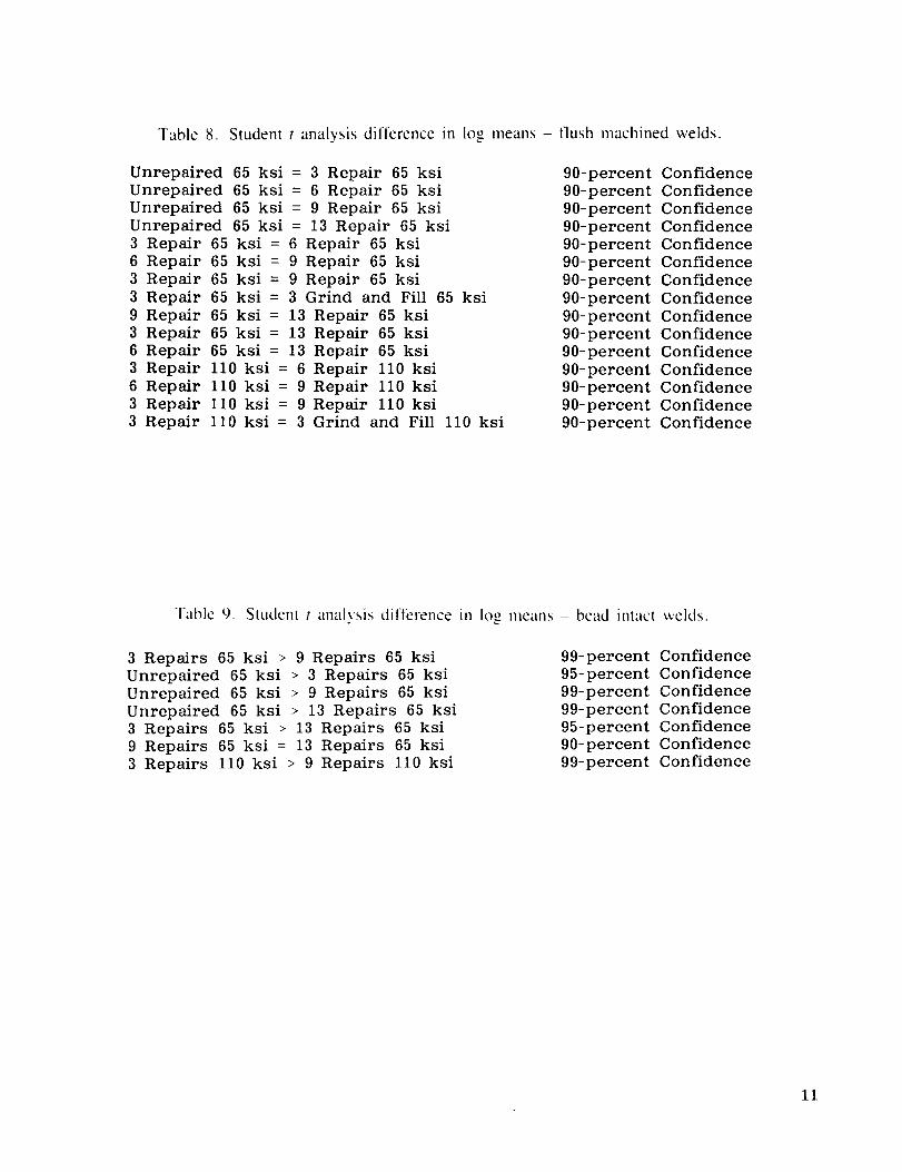
Student t analysis difference in log means - flush machined welds ........................... 1 i
Student t analysis difference in log means - bead intact welds ................................ 1 I
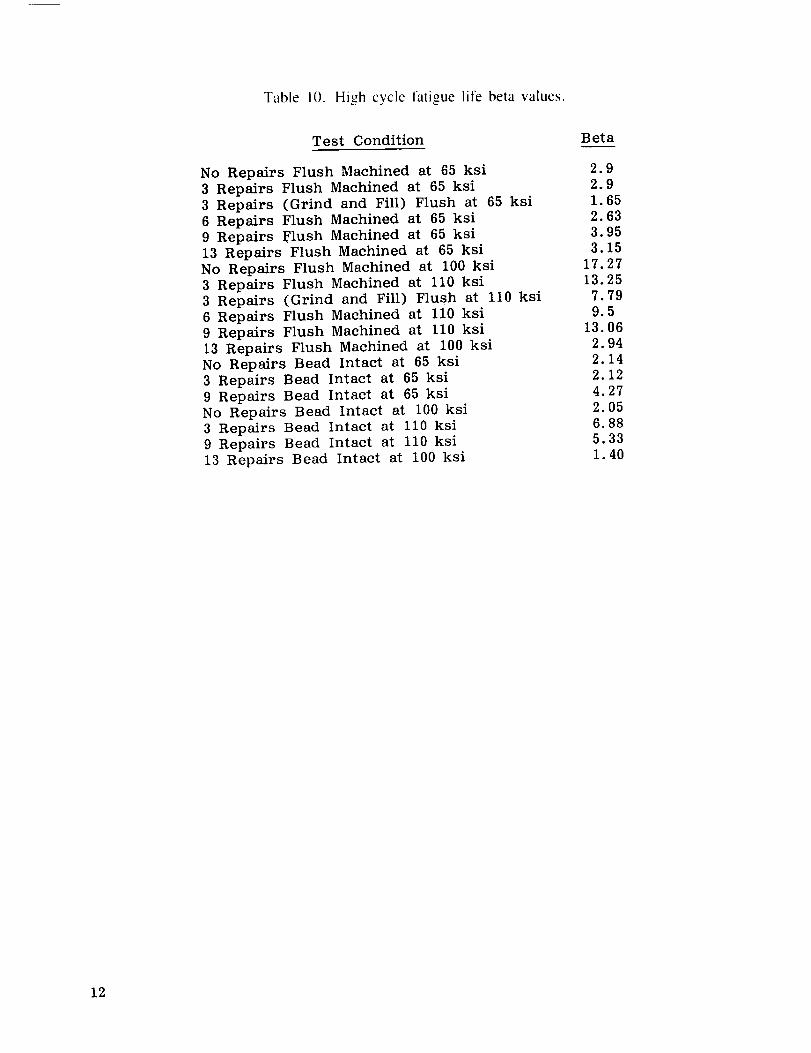
High cycle fatigue life beta values ................................................................ 12
"V
TECHNICAL MEMORANDUM
THE EFFECTS OF MULTIPLE WELD REPAIRS ON INCONEL 718
WELD MECHANICAL PROPERTIES
I. INTRODUCTION
A. Background
Inconel 718 is a nickel-based, austenitic, precipitation-hardenable alloy, introduced by the
Huntington Division of the International Nickel Co.. in 1959. As with all superalloys. Inconel 718
has material property characteristics enabling high-temperature, high-strength design applications in
corrosive environments, such as found in the space shuttle main engine (SSME}. Inconel 718 is
available in all material forms (wrought. cast. forged) and is readily weldable in both the annealed
and age-hardened conditions ll.2].
The SSME is a reusable, high-pertormance, liquid-fueled rocket engine whose operating
conditions necessitate the wide use of superalloys [3]. The engine is assembled with over 5,000
_sclded joints produced primarily with the gas tungsten arc (GTA) and electron beam (EB) welding
processes. In spite of the complex nature of many of the weld ,joints, strict quality control
requirements apply. The nondestructive inspection methods of dimensional (visual). radiographic,
ultrasonic, and fluorescent dye-penetrant are required.
GTA welding is performed both manually and semiautomatically. Production acceptance
rates for weld quality average 95 percent. This implies that 5 percent of the welded inches require
repair at least once. and repeated repair attempts are not uncommon. In 1981. NASA/Marshall
Space Flight Center (MSFC) conducted an experiment to determine if multiple repairs degraded the
material properties of Inconel 718 14l. GTA welds on 0.25- and 0.50-in wrought plates were
repaired 13 times to determine if tensile or high-cycle fatigue properties were degraded. Tensile test
results, for both longitudinal and transverse weld specimens, showed no degradation with multiple
repairs. Fatigue tests were also conducted with longitudinal, all-weld-metal specimens. Again, the
results showed no degradation in high-cycle fatigue life with multiple repairs. The test matrix did
not include transverse weld specimens: therefore, the effects, if any, of multiple repairs on theweld heat affected zone (HAZ) were not evaluated.
B. Objective
The objective o1 this research was to reevaluate the effects of multiple repairs on Inconel
718; weldmcnts. Tensile and high-cycle fatigue properties were again tested, this time including
parent metal and HAZ, in addition to the weld fusion zone. Specimens were tested both with the
weld bead l]ush machined {to eliminate geometry effects) and with the w'eld bead intact. Statistical
analyses were used to determine, to a given statistical level of significance, any differences in
properties between welds not repaired and those repeatedly repaired.
II. EXPERIMENTAL PROCEDURE
A. Population Selection
The effects of repairing on the physical and metallurgical properties of Inconel 718 were
anticipated to increase linearly. Therefore, three, six. and nine repairs were selected to provide the
data on repair effects. Mechanical property data for the control samples, in this case welds made
without repairing, were available from previous programs conducted at MSFC and were not dupli-
cated here 15,6]. The earlier program 151 examined the effects of 13 repairs on lnconel 718 so the
mechanical property data for 13 repairs were also included on comparisons with three, six, and
nine repairs. Bead profile measurements of the weld root were made of the welds with the bead
left intact lor accurate accountability of the actual conditions. A laser sensor system currently under
developrnent at MSFC was used tk)r these measurements. A typical bead profile using the develop-
merit sensor is shown in figure I. All welds were made to meet the requirements for bead shape
described in the Rocketdyne fusion welding specification RLI0011 17]. These requirements for
0. 125-in material are: maximum weld width 0.440 in, maximum weld drop through 0.072 in,
maximum weld height 0.072 in.
Most of the welds on the SSME are post-weld heat treated to the STAi condition. This is a
solution anneal and aging heat treatment developed jointly by Rocketdyne and NASA to provide
adequate material properties. Welds are annealed at 1,900 °F for 30 rain tollowed by an argon
quench. Age hardening is obtained by heating to 1,400 °F tor 10 h, furnace cooled to !,200 °F,
and held at 1,200 °F tor a time period sufficient to have the aging cycle at both temperatures equal20 h total.
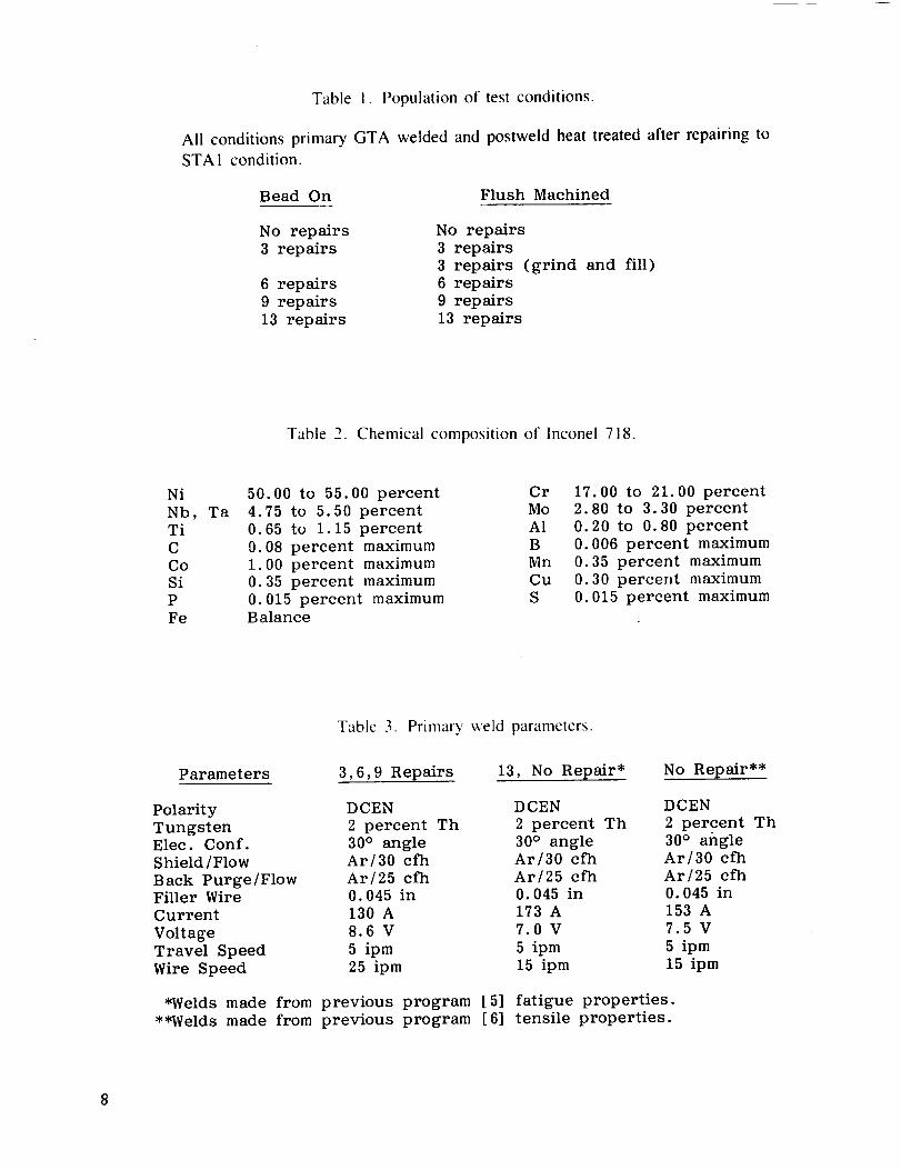
The total population of test conditions is shown in table 1.
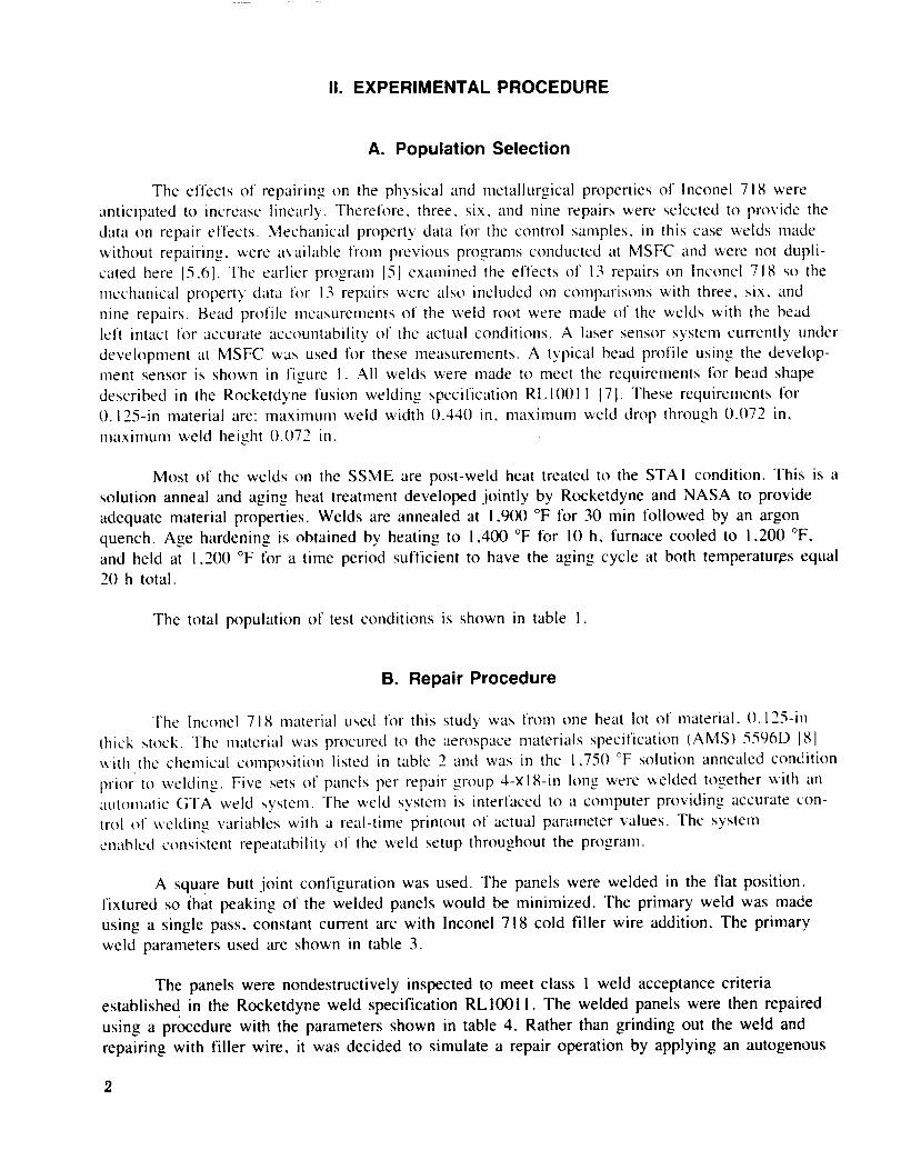
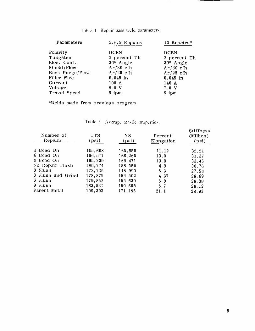
B. Repair Procedure
The lnconel 718 material used lot this study was from one heat lot of material. 0.125-in
thick stock. The material was procured to the aerospace materials specification (AMS) 5596D la;I
with the chemical composition listed in table 2 and was in the 1.75(/ °F solution annealed condition
prior to wekting. Five sets of panels per repair group 4-xl8-in long were welded together with an
autonlalic GTA weld system. The weld system is interfaced to a computer providing accurate con-
trol of welding variables with a real-time printout of actual parameter values. The system
enabled consistent repeatability of the weld setup throughout the program.
A square butt joint configuration was used. The panels were welded in the fiat position.
fixtured so ihat peaking of the welded panels would be minimized. The primary weld was made
using a single pass. constant current arc with Inconel 718 cold filler wire addition. The primary
weld parameters used are shown in table 3.
The panels were nondestructively inspected to meet class I weld acceptance criteria
established in the Rocketdyne weld specification RLI0011. The welded panels were then repaired
using a pr_edure with the parameters shown in table 4. Rather than grinding out the weld and
repairing with filler wire, it was decided to simulate a repair operation by applying an autogenous
2
weld passthat would remeitapproximately50 percentof the weld. This wasdoneto expedite the
repairing operation. Panels were repaired for l-in lengths separated by 2-in increments as shown in
figure 2. This sequence was selected so that stresses induced by surrounding cold metal on the
repair solidification would be adequately duplicated. Three, six, nine, and 13 repairs were simu-
lated in this manner. To validate the simulation method, a set of panels were also ground and
repaired with filler wire three times.
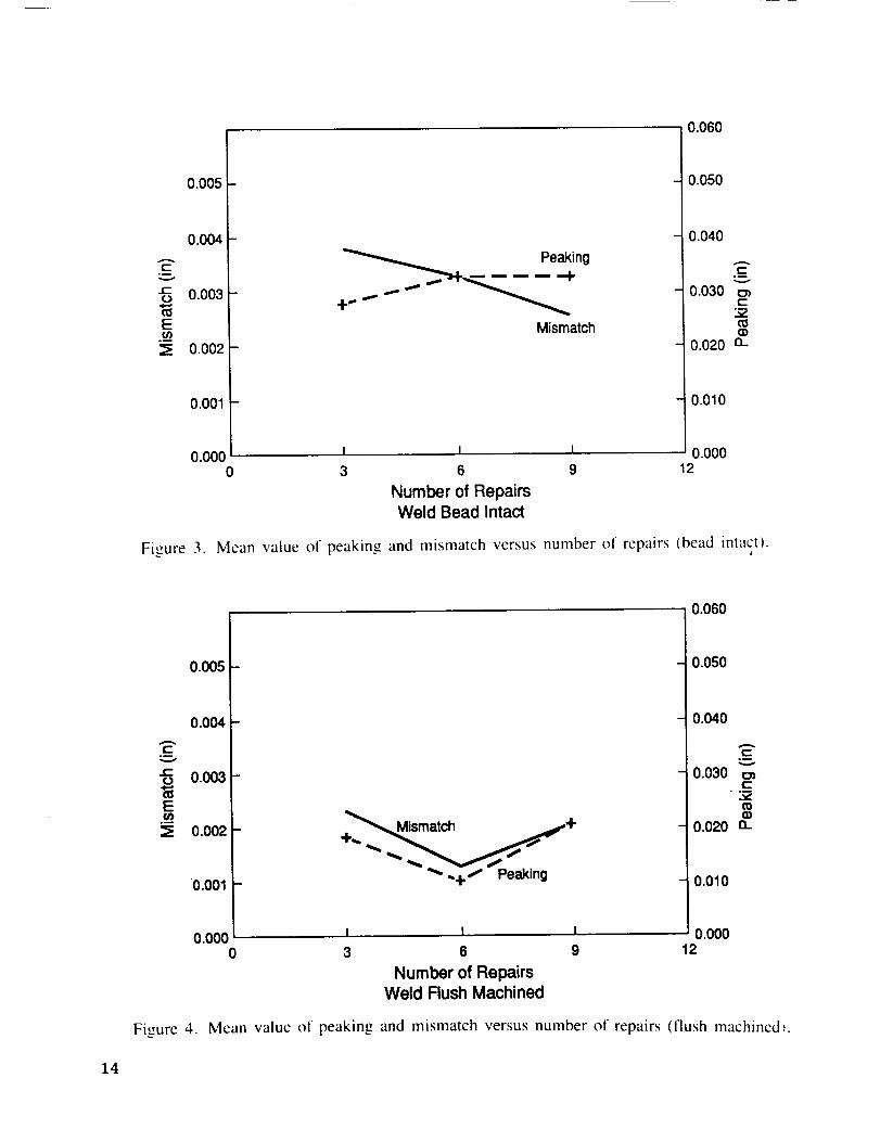
All repaired welds were again inspected to class 1 requirements. Peaking and mismatch
were also measured on the machined specimens. The mean value of peaking and mismatch
measured for bead intact and flush machined three, six, and nine repaired specimens are shown in
figures 3 and 4, respectively. Figure 3 shows a definite trend as the number of repairs increases.
Peaking increases with increasing repairs and mismatch decreases. The increase in peaking would
be expected as each repair pass induces additional thermal distortion of the panels. The test
specimens that were flush machined lk)llow the same trend for peaking and mismatch as the
number of repairs increases as seen in figure 4. All measurements are within specification
tolerances of 0.025 in lk)r mismatch and 5 ° lk)r peaking (per MSFC specification 560A 19]).
C. Evaluation Test Specimens
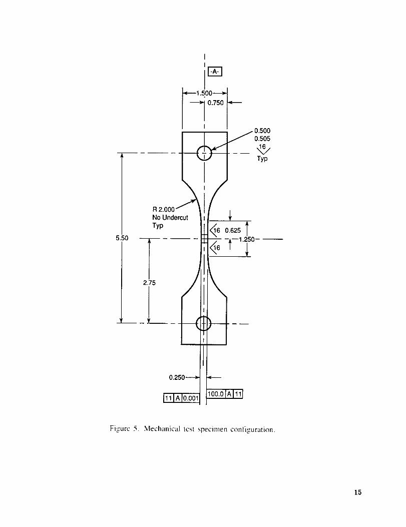
Weld-repaired areas were cut from the panels into mechanical test specimens of the con-
figuration shown in figure 5 conforming to the guidelines established in the ASTM E8 [10] and
ASTM E466 [I I I specifications.
A student t analysis was used to compare the statistical means and statistical minimums of
ultimate and yield strength properties for repaired and unrepaired welds. A student t analysis
comparing difference in log means of high-cycle fatigue life for repaired and unrepaired welds at
the two stress levels was also performed. Finally, a Weibull B I life analysis was used to evaluate
repaired versus unrepaired weld high-cycle fatigue lives at two stress levels.
III. RESULTS AND DISCUSSION
A. Metallographic Analysis
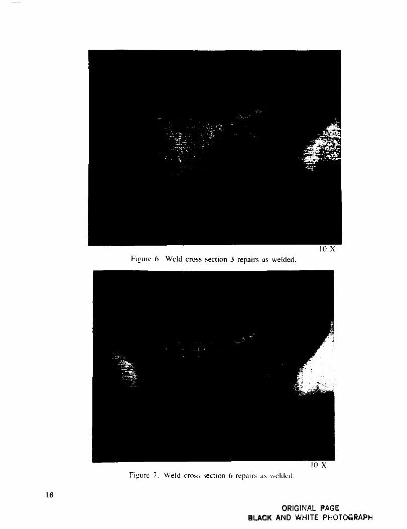
Cross sections were taken from each repair condition, three, six, and nine times, as well as
an unrepaired weld to compare fusion zone and heat-affected zone metallographic structures. All
samples were electrochemically etched in tin oxalic acid solution. The as-welded macrostructures
sire shown in figures 6 through 8. The repair weld passes are seen to penetrate approximately 50
percent of the weld fusion zone. Higher magnification micrographs for the same weldments reveal
minor differences in HAZ size and weld fusion zone solidification structures. The HAZ appears
much wider tit the root of the weld than at the face side. The dendritic spacing in the repaired por-
tion of the fusion zone is much smaller than in the unrepaired fusion zone. This is expected with
the lower heat input and associated smaller molten puddle. The width of the primary weld pass
appears to increase as the number of repairs increases. One possible explanation of this is a shift in
the Marangoni flow pattern within the molten weld pool during welding. The Marangoni flow is
outward toward the edge of the puddle for "pure" metals and is driven inward by contamination of
the surface. Perhaps the repair weld heat passes clean the surface such that the weld surface is
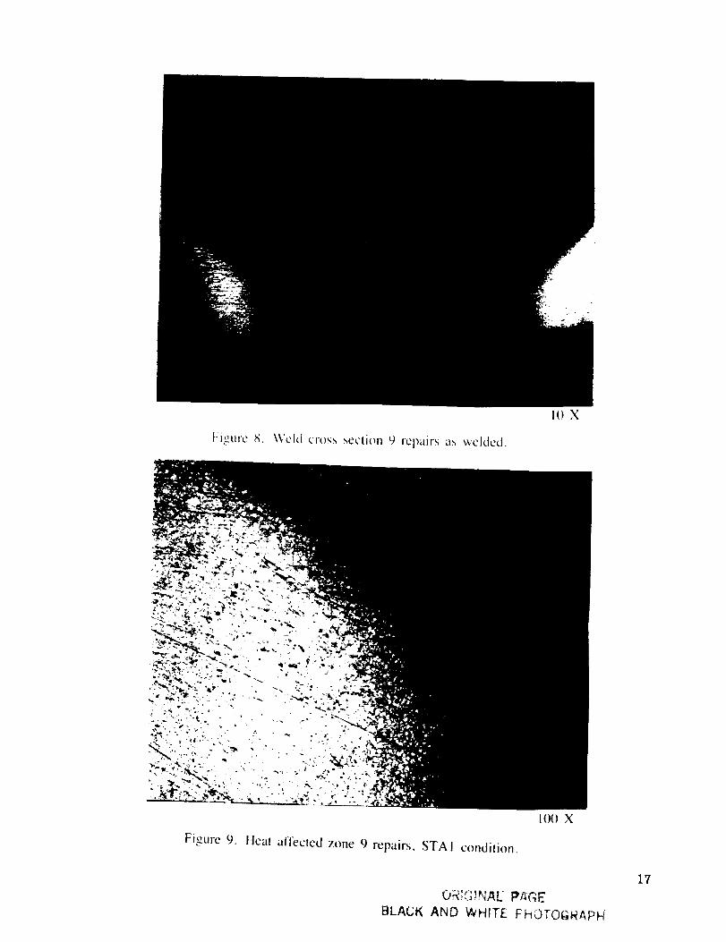
more "pure." The multiple repairing effects on the heat-affected zone grain growth region are
eliminated in the subsequent postweld heat treatment as represented in figure 9.
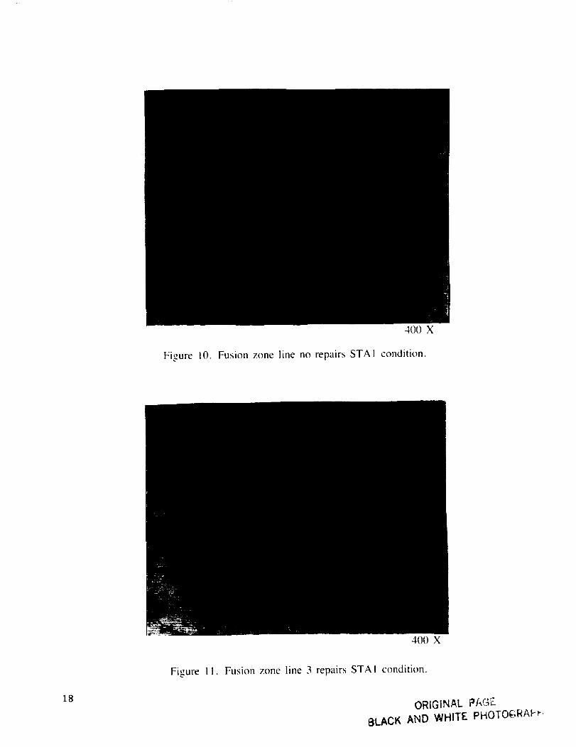
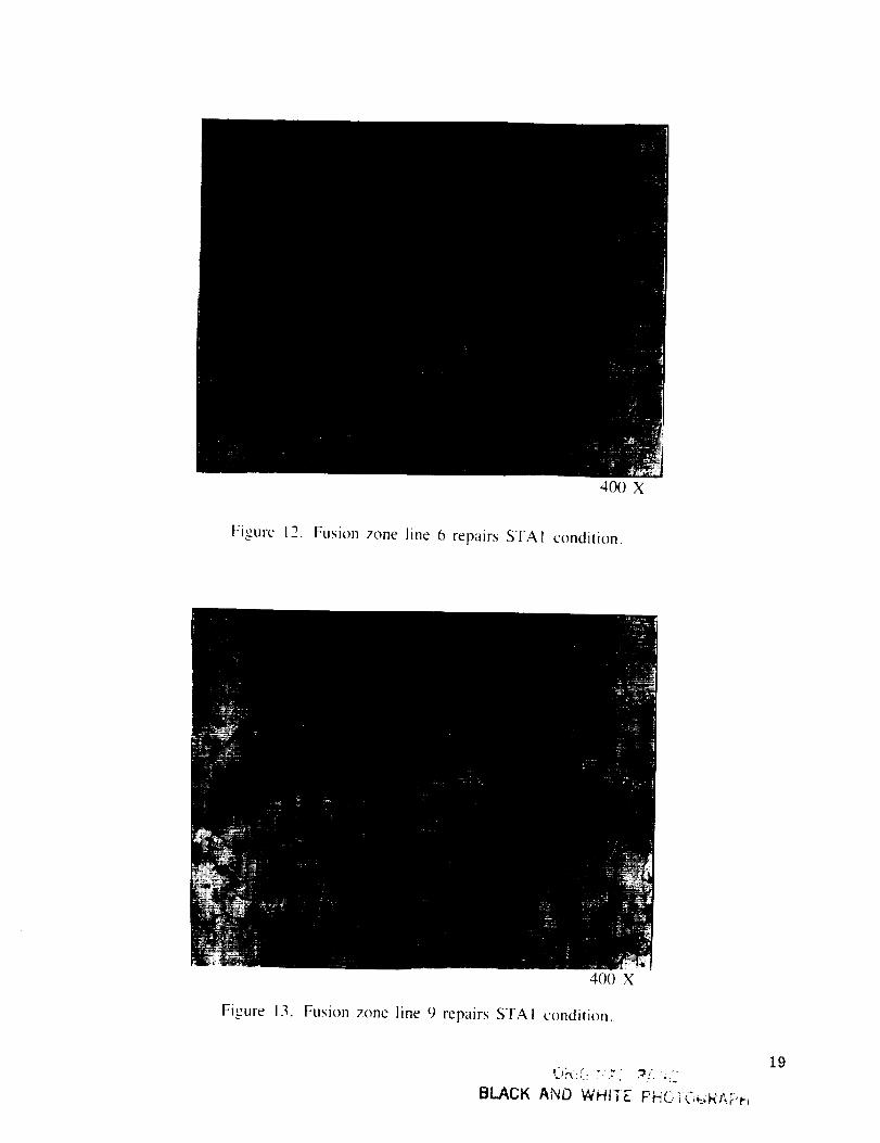
Microstructures of the STAI weldments at the equiaxed to dendritic transition at the weld
fusion interface are shown in figures 10 through 13. Delta phase of Ni3Nb precipitates are seen in
the gamma double prime matrix, mostly at grain boundaries. The amount of delta phase in the
unrepaired micrograph is much less than all three repair micrographs. Laves phase is observed
within the delta phase, appearing white in the micrographs. Carbides are dispersed throughout the
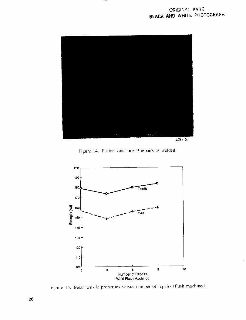
matrix and do not appear to be affected by repairing. Figure 14 shows the same area in the weld
prior to postweld solution treating and aging.
B. Tensile Strength Analysis
Tensile tests were run using a Tinius Olsen (DS-30) servo-hydraulic tensile testing machine.
Ultimate tensile strength, yield strength, elongation, and modulus were determined tot three, six.
and nine repairs, for specimens both with weld bead intact and weld bead flush machined, and for
parent metal specimens. Tensile properties for unrepaired welds with the bead flush machined were
available from a previous NASA program [6] using only 10 randomly selected data points to
eliminate population size artifacts from the analysis. Average values for the above properties are
listed in table 5. Bead-on tensile specimens all broke in the parent metal, away from the weld
fusion zone and heat-affected zone. There appears to be no degradation in tensile properties as the
number of repairs increases. Percent elongation increases slightly as number of repairs increases.
Comparing the bead-on tensile properties to the parent metal control specimen tensile property
results shows some degradation in properties due to welding even though both broke in the parent
metal. This could be the result of peaking and mismatch induced during welding, although actual
measured values were very small. Ductility. as measured by percent elongation, is greatly reduced
t\_,r welded specimens compared to parent metal specimens.
The tensile properties for flush-machined weld specimens show an increase in average
ultimate tensile and yield strength as the number of repairs increases. However, unrepaired welds
had higher average ultimate and yield strength than three and six repairs, but lower than nine
repairs. Percent ehmgation and stiffness appear to be unaffected by increasing repairs. The tensile
test specimens with flush-machined weldments all failed in the weld fusion zone.
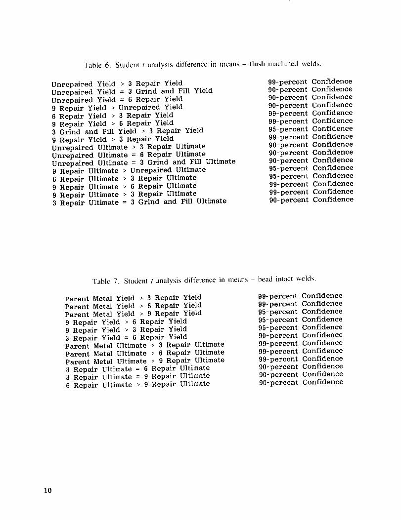
A student t statistical analysis was done to compare difference in means fc_r ultimate and
yield properties between repaired welds and unrepaired welds. Confidence levels of 90 percent or
greater 195 and 99 percent) were used for the analysis to assure adequate conservatism in the
analysis results. A summary of these results for llush-machined welds is listed in table 6. The
student t analysis confirmed that unrepaired welds were higher in yield strength than three-times
repaired welds for flush-machined welds. There was no discernable difference in means for yield
strength between unrepaired and three-repairs {with grind and fill) and six-repairs llush-machined
welds. The nine-times repaired flush-machined welds were greater in yield strength than an
unrepaired weld.
4
The studentt analysis lor difference between unrepaired and repaired weld mean strengths
for flush-machined welds followed the same trend as for yield strength. The ultimate tensile
strength tot nine repairs is greater than for unrepaired welds. The comparison of welds repaired
three times with an autogenous heat pass to welds repaired three times by grinding and filling
showed no discernable difference in means for ultimate strength and a slight increase in yield
strength for the grind and fill repairs. This implies the autogeneous heat pass is a good simulation
of a repair operation. Figure 15 also illustrates the minimal effect of multiple repairs on mean
tensile and yield strengths. In fact. a decrease of 5 ksi on tensile strength relates to a 3-percent
reduction in strength of an unrepaired weld.
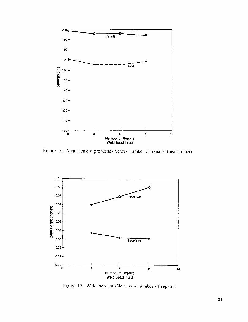
The results of the student t analysis, comparing the difference in means between repaired
welds with the weld bead left intact and parent metal specimens are listed in table 7. Parent metal
samples had higher yield and tensile strengths than all repaired welds to a 99-percent confidence
level. This is opposite to what is expected since repaired welds also failed in the parent metal, well
away from the weld fusion zone and HAZ region of the weld. The reduction in tensile properties
of the repaired welds, however, is small (approximately 1 percent of the parent metal properties).
Comparison of the number of repaired bead-intact welds shows yield strength first dropping off,
then improving as number of repairs increases. There is no discernible difference in means on
ultimate strength except six repairs are better than nine repairs. Yield strength appears to improve
with multiple repairs. Figure 16 graphically shows the effects of multiple repairs on mean tensile
and yield strength lot welds tested with the bead intact. Again, the amount of degradation on
properties is insignificant.
C. Fatigue Property Analysis
High-cycle fatigue tests were conducted on all repair groups at two stress levels. Problems
during testing resulted in scrapping a significant number of specimens so that fatigue curves could
not be generated. High- and low-stress levels were selected so that specimens would fail alter
approximately I(X),000 cycles and 1,0(X),0(X) cycles, respectively. The stress levels chosen were
II0 ksi and 65 ksi. An R ratio (minimum stress divided by maximum stress) of 0.05 was selected
to represent engine operating conditions. During testing, a load cell had to be replaced, and the
new cell was not recalibrated. This discrepancy was not noticed until after all the six repairs, weld
bead-on test specimens were tested. This was calculated to result in stress levels of 77 ksi and 131
ksi at an R ratio of 0,205. Theretore the data for the six repairs, bead-on high-cycle fatigue were
dropped from the subsequent analyses. The tests were conducted on a Sontag servo-hydraulic
fatigue tester cycling at 30 Hz. Unrepaired-weld, high-cycle fatigue data from a previous program
were used as controls. However, these data, as well as weld high-cycle fatigue data for 13 repairs
were generated on a 10K MTS servo-hydraulic fatigue tester cycling at 40 Hz. The high stresslevel was chosen as I()0 ksi, the low stress level was 65 ksi, and the R ratio was 0.05.
All high-cycle fatigue specimens failed through the weld fusion zone lor the flush-machined
weld bead. and at the fusion boundary for the specimens with the weld bead left intact. Thus,
multiple repairs do not affect the weld HAZ in that the position of failure did not change between
welds repaired versus unrepaired flush machined, and between welds repaired versus unrepairedweld bead left intact.
5
A studentt analyis was done comparing the difference in log means of the number of
cycles to failure for the different repair groups at the two stress levels. The results of this analysisare summarized in table 8 for flush-machined welds and in table 9 for bead-intact welds. The
flushed-weld data showed no discernible difference to a 90-percent confidence level for all groups
compared. There was also no discernible difference in log means of cycles to failure between
unrepaired welds and repaired welds for both stress levels. Also, there was no discernible differ-
ence in log means of welds receiving a simulated repair (heat pass) versus a grind and fill repair at
the two stress levels tested. However, there is a difference in log means between repair groups
with the weld bead left intact (table 9). To a 99-percent confidence level, welds repaired three
times are better than welds repaired nine times at the two stress levels tested. This substantiates the
previous program results comparing 13 repairs to unrepaired welds with the weld bead left intact.
This implies that the degradation is due to an increase in the stress intensity factor, or a geometry
effect, lnconel 718 is known to be notch sensitive [12] which correlates with the increase in weld
bead height measured at the root of the weld as the number of repairs increases. Figure 17 shows
the average bead height tor the repaired welds measured from the weld face side and root side. A
definite trend is observed as the number of repairs increases. The bead height on the weld face
decreases with increasing repairs, and the drop through increases as the number of repairs
increases. This could be related to the transient thermal compressive stresses induced in the
material below the repair weld puddle extruding the weld metal out the bottom of the weld. This
would imply that distortion of the welded panels would also increase due to the extrusion. This
was verified previously in figure 7, which showed peaking to increase as the number of repairsincreased.
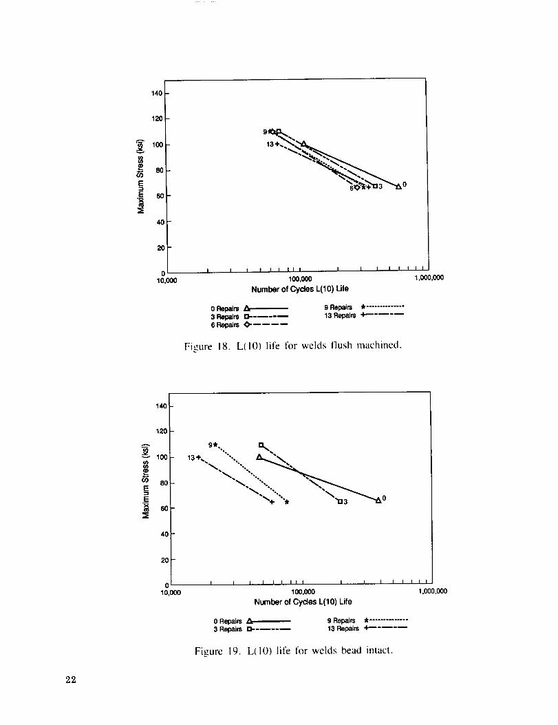
A Weibull analysis was also done on all high-cycle fatigue data. A list of the beta values is
given in table 10. The beta value, or slope of the line, indicates the failure mode of the popula-
tion. Low values imply low time failures or scatter in the data. High beta values represent a
"'wearout" failure mode [131.
Figure 18 shows the plot of the L(10) life for each test condition with the weld beads flush
machined. The L(10) life represents the number of cycles above which 90 percent of the population
will fall. First, the unrepaired and 13-repaired plots have the same slope. But the three, six, and
nine repairs have a different slope (approximately the same), implying the different weld
parameters used between the two programs biased the results. Another possible cause might be the
10-Hz difference in cyclic frequency between the two fatigue testing machines used, however, a
difference of 10 Hz certainly seems insignificant. The six- and nine-repair fatigue lives at 65 ksi
are less than the 13 repaired. At the high stress level, the three-repair line crosses the unrepaired
line, implying three repairs are better than none at high-stress levels. Nevertheless, at the low-stress
level, the repaired welds failed approximately 200,000 cycles before the unrepaired welds.
Figure 19 shows the L(10) life for each test condition with the weld beads left intact.
Again, different slopes are observed lor the 13- and no-repair conditions compared to the three-
and nine-repair conditions. A noticeable degradation in life is evident at both stress levels.
Fracture surfaces were analyzed with no conclusive results on failure initiation point trends.Most failures initiated at a comer, the most likely location of the highest stress intensity. There was
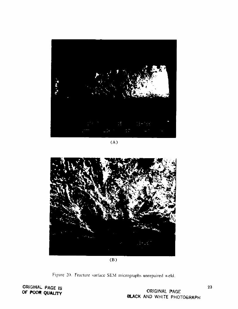
no correlation in failure from the face or root side of the weld with cycles to failure. Figure 20 shows a
fracture surface using scanning electron microscopy (SEM) of an unrepaired-weld high-cycle fatigue
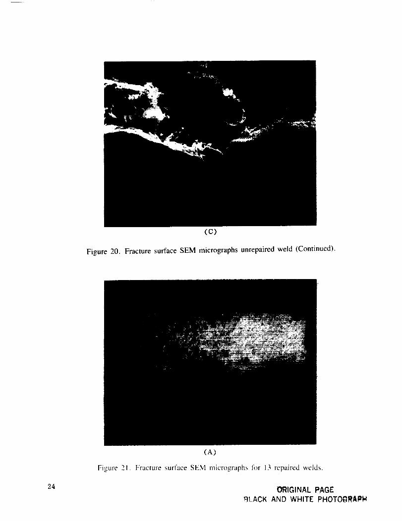
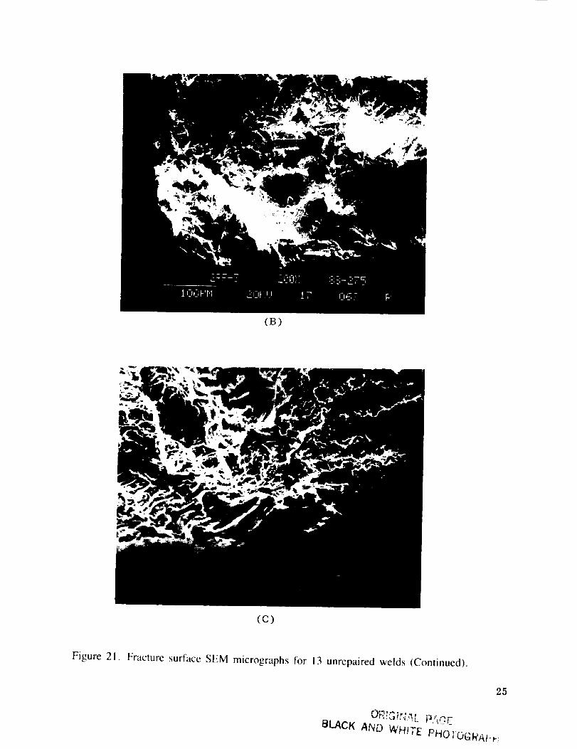
specimen tested at 100 ksi. Figure 21 shows a fracture surface of a weld repaired 13 times and high-
cycle fatigue tested at 65 ksi. Secondary cracks can be found, but no higher order precipitates.
IV. CONCLUSIONS
1. Multiple repairs on Inconel 718 weldments do not affect the HAZ such that mechanical
properties are altered.
2. Multiple repairs do not degrade tensile properties to a level of engineering significance.
3. High-cycle fatigue tests of flush-machined welds at high stress levels are not affected by
repairs, but at low-stress levels the fatigue life is somewhat reduced as the number of repairsincreases.
4. High-cycle fatigue tests of bead-intact welds exhibit reduced fatigue life as the number of
repairs increases at both high- and low-stress levels.
5. The weld root bead height increases linearly as the number of repairs increases.
Table I. Population of test conditions.
All conditions primary GTA welded and postweld heat treated after repairing toSTA ! condition.
Bead On Flush Machined
No repairs3 repairs
6 repairs9 repairs13 repairs
No repairs3 repairs3 repairs (grind and fill)6 repairs9 repairs13 repairs
Table 2. Chemical composition of lnconel 718.
Ni
Nb,Ti
CCo
Si
P
Fe
Ta
50.00 to 55.00 percent
4.75 to 5.50 percent
0.65 to 1.15 percent
0.08 percent maximum1.00 percent maximum
0.35 percent maximum
0.015 percent maximumBalance
Cr 17.00 to 21.00 percentMo 2.80 to 3.30 percentAI 0.20 to 0.80 percentB 0. 006 percent maximumMn 0.35 percent maximumCu 0.30 percent maximumS 0. 015 percent maximum
Table 3. Primary weld parameters.
Parameters 3,6,9 Repairs 13, No Repair* No Repair**
Polarity DCEN D CEN DCEN
Tungsten 2 percent Th 2 percent Th 2 percent ThElec. Conf. 30 ° angle 30 ° angle 30 ° angleShield/Flow Ar/30 cfh Ar/30 cfh Ar/30 cfhBack Purge/Flow Ar/25 efh Ar/25 cfh Ar/25 cfhFiller Wire 0.045 in 0.045 in 0.045 inCurrent 130 A 173 A 153 AVoltage 8.6 V 7.0 V 7.5 V
Figure 20. Fracture surtace SEM micrographs unrepaired _eld.
ORiGIN,_L PAGE ISOF POOR QUALfl'Y ORIGINAL PAGE
BLACK AND WHITE PHOTOGRAPH
23
(C)
Figure 20. Fracture surface SEM micrographs unrepaired weld (Continued).
24
(A)
Figure 21. Fracture surface SEM micrographs t'or 13 repaired welds.
ORIGINAL PAGE
_Jt.ACK AND WHITE PHOTOGRAPH
(B)
(c)
Figure 21. Fracture surface SEM micrographs tor 13 unrepaired welds (Continued).
25
OR!S !t4,,'_L P,qCE
BLACK AND V4HITE PHOY-- •
REFERENCES
I °
.
.
.
.
Sessler. J., and Weiss, V.: "'Materials Data Handbook lnconel Alloy 718.'" Syracuse Univer-
sity, NASA Tech Brief 67-10282. 1967.
Fawley, R.W.: Superalloy Progress. "'The Superalloys,'" John Wiley and Sons, Inc., 1972.
pp. 3-30.
Space Shuttle Main Engine. Space Transportation System Technical Manual, RocketdyneDivision. Rockwell International. Publication E41000, RSS-8559-1-1-1. NASA contract
NAS8-27980, 1983.
Bayless. E.O.. el al.: "'Considerations on Repeated Repairing of Weldments in lnconel 718
Alloy." NASA Technical Memorandum NASA TM-82409. 1981.
Gamwell, W.R.. and Malone, T.W.: "'Effects of Weld Repair on Weld Heat Affected Zone
CHAZ) in lnconel 718.'" NASA memo EH23 (87-90), MSFC, 1987.
(B)
(c)
Figure 21. Fracture surface SEM micrographs for 13 unrepaired welds Conlinued).
BLACK AND WHITE PHO1OGRAI-t-;
25
REFERENCES
I o
.
,
.
.
.
o
,
9.
10.
II.
12.
13.
Sessler, J.. and Weiss. V.' "'Materials Data Handbook lnconel Alloy 718.'" Syracuse Univer-
sit\',, NASA Tech Brief 67-10,8,,"_ "_ 1967.
Fawley, R.W. Superalloy Progress. "'The Superalloys,'" John Wiley and Sons, Inc., 1972.
pp. 3-30.
Space Shuttle Main Engine. Space Transportation System Technical Manual, RocketdyneDivision, Rockwell International, Publication E41000, RSS-8559-1-1-1, NASA contract
NAS8-27980, 1983.
Bayless. E.O., et al. "'Considerations on Repeated Repairing of Weldrnents in Inconel 7t8
Alloy." NASA Technical Memorandum NASA TM-82409. 1981.
Gamwell. W.R.. and Malone, T.W.: "'Effects of Weld Repair on Weld Heat Affected Zone(HAZ) in lnconel 718.'" NASA memo EH23 (87-90), MSFC, 1987.
Gamwel[. W.R.. Kurgan, C., and Malone, T.W. "An Evaluation of GTAW-P Versus GTA
Welding of Alloy 718.'" NASA Technical Memorandum TM-103529. 1991.
Macfarlane, D.I.: "'Fusion Welding Process and Quality Requirements for the SSME.'" Speci-
fication RLI001 I. Rocketdyne Division, Rockwell International. 1988.
Aerospace Material Specification AMS 5596D, Society of Automotive Engineers. Inc., 1981.
Kurgan, C., et al. "'Process and Quality Requirements for Welding Corrosion and Heat