ADA094 192 AIR FORCE WRIGHT AERONAUTICAL LABS WRIGHT-PATTERSON AFS OH F/G 20/5 EXPERIMENTS WITH A SUPERSONIC MULTI-CHANNEL RADIAL OIFFUSER.IU) SEP 80 S H HASINBER' H L TOMS -* Fn F WWAL-TR-80-3029 EEEEEwoEEEEEEE
Transcript
ADA094 192 AIR FORCE WRIGHT AERONAUTICAL LABS WRIGHT-PATTERSON AFS OH F/G 20/5
EXPERIMENTS WITH A SUPERSONIC MULTI-CHANNEL RADIAL OIFFUSER.IU)
SEP 80 S H HASINBER' H L TOMS-* Fn F WWAL-TR-80-3029
EEEEEwoEEEEEEE
IIII1 j32III I ' -!_. -
Iit'il11111 102IIIIN IlIIIII 8
111111-25 1.4la~ ff 1.6
MICROCOPY RESOLUTION TEST CHART
NA TON AL 3 JRIJ l ( SI AN )AIDS Iq( .3 A
AFW~AL-TR-80-3029 rrw
, -A
C EXPERIMENTS WITH A SUPERSONIC MULTI-CHANNEL
RADIAL DIFFUSER
Siegfried H. HasingerHoward L. Toms Jr.Thermomechani cs BranchAero Mechanics Division
September 1980
O TECHNICAL REPORT AFW/ETR-80-3029
L Final Report for Period November 1978 - September 1979
JApproved for public release, distribution unjimited]
FLIGHT DYNAMICS LABORATORYAIR FORCE WRIGHT AERONAUTICAL LABORATORIESAIR FORCE SYSTEMS COMMANDWRIGHT-PATTERSON AIR FORCE BASE, OHIO 4543381 1I 26 162
NOTICE
when Government drawings, specifications, or other data are used for any p, :poseother than in connection with a definitely related Government procurement operation,the United States Government thereby incurs no responsibility nor any obligationwhatsoever; and the fact that the government may have formulated, furnished, or inany way supplied the said drawings, specifications, or other data, is not to be re-garded by implication or otherwise as in any manner licensing the holder or anyother person or corporation, or conveying any rights or permission to manufactureuse, or sell any patented invention that may in any way be related thereto.
This report has been reviewed by the Office of Public Affairs (ASD/PA) and isreleasable to the National Technical Information Service (NTIS). At NTIS, it willbe available to the general public, including foreign nations.
This technical report has been reviewed and is approved for publication.
SIEGFRIED H. HASINGER J. CHRISTOPHER BOISONAerosp Engr, Thermomechanics Branch Chief, Thermomechanics BranchAeromechanics Division Aeromechanics Division
FRTECOM 7ER
PETER JAW IZ Col, AVChief, romechanics D v s o
Flightynamics Laboratory
"If your address has changed, if you wish to be removed from our mailing list, orif the addressee is no longer employed by your organization please notify AFWAL/FIME,W-PAFB, OH 45433 to help us maintain a current mailing list".
Copies of this report should not be returned unless return is required by security
considerations, contractual obligations, or notice on a specific document.
AIR FORCE/I670/15 December 1960 - 100
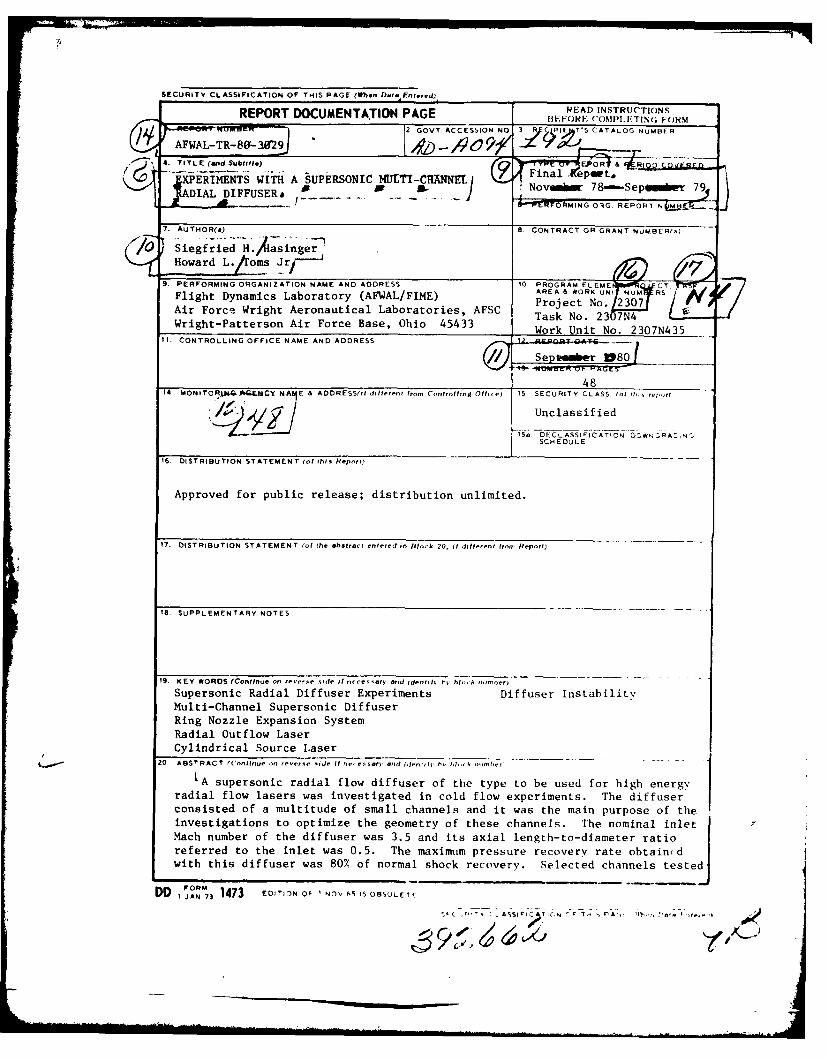
SECURITY CLASSIFICATION OF THIS PAGE (When Di E.nterd)REO~i DOCMENTTIO. PGE _ / READ INSTRUCTIONSREOR DOUETATO PGEFOC)F"OMPI.F-TING F ORM
AFWAL-TR-80- 30129 P - -/)O/. 4. TITLE (and Subtitle) EIt &0 OEE
XPERIMENTS WITH A SUPERSONIC MULTI-CRANa p'AIA PEMTDI FFUSER&H m B I- / , Novoub 78-Sepenm 79A L . .... ... .. W"'rrORMING 0O'RG. REPORT N _
7. AUTHO R(.) 8 CONTRCT OR GRANT NUMBRs
9. PERFORMING ORGANIZATION NAME AND ADDRESS 10 PROGRAM ELEME FIiOJCT _ P
Fl ight Dynamics Laboratory (AFWAL/FIME) ARoE& WO U N I- NUM RS
Air Force Wright Aeronautical Laboratories, AFSC Project No. 2307
Wright-Patterson Air Force Base, Ohio 45433 Work No. 2307N4Work Unit No. 2307N435
1. CONTROLLING OFFICE NAME AND ADDRESS -' e p 80
4814 MONITOR.MI4 AQMCY NAAIE & AODRESS(il different frnt (oOtr ff-)in O 15 SECURITY CLASS. (of th-.;-,t
Unclassified
,S. DECL ASSIFICATION 6D O NRA. N;SCHEDULE
16. DISTRIBUTION STATEMENT (of this Repont)
Approved for public release; distribution unlimited.
17. DISTRIBUTION STATEMENT (o the *bsta~c entered nRItok 20, it dffttt Iton, Report)
IS. SUPPLEMENTARY NOTES
19. KEY WORDS (Continue o- everse n--de -o -ties ary and sdenhtr h, bt ti t,'ner)
20 ABSTRACT (CntInu- - revea'se Ode It ne,ensar and itd'-ri h% hl P tther'
LA supersonic radial flow diffuser of the type to be used for high energyradial flow lasers was investigated in cold flow experiments. The diffuserconsisted of a multitude of small channels and it was the main purpose of the
investigations to optimize the geometry of these channels. The nominal inletMach number of the diffuser was 3.5 and its axial length-to-diameter ratioreferred to the inlet was 0.5. The maximum pressure recovery rate obtaindwith this diffuser was 807 of normal shock recovery. Selected channels tested
FORMDD I JAN 73 1473 EDITION Of I NO\, 65. IS OBSULETIF
',ASS. I
oe 4e#
SECURITY CLASSIFICATION OF THIS PAGE(When Date Entared)
individually reached a recovery rate of over 100%. Failure of the diffuser as a
whole to reach this performance must be attributed to flow instabilities
triggered by flow irregularities inherent to the present radial flow system.
SEC" )NlTYf C-L&SSFICATIO1, OFr
T,, P;7-,47 i" ,r Dafe F ft-
4
AFWAL-TR-80-3029
FOREWORD
This is the final report on the investigations of supersonic radial
diffusers, covering the experimental phase of this effort. This work was
carried out under Work Unit No. 2307N435 of Project No. 2307 in the
from November 1978 to September 1979. An earlier report on these inves-
tigations is AFWAL-TR-80-3028-.ntitled "Analysis and Design of a Supersonic
Radial Outflow System".
Special recognition goes to Capt. David K. Miller who initiated this
effort and followed it with great interest and valuable advice during the
time he was in charge of this effort as Technical Manager.
iI
iii
L - ' -.-- .- I
AFWAL-TR-80-3029
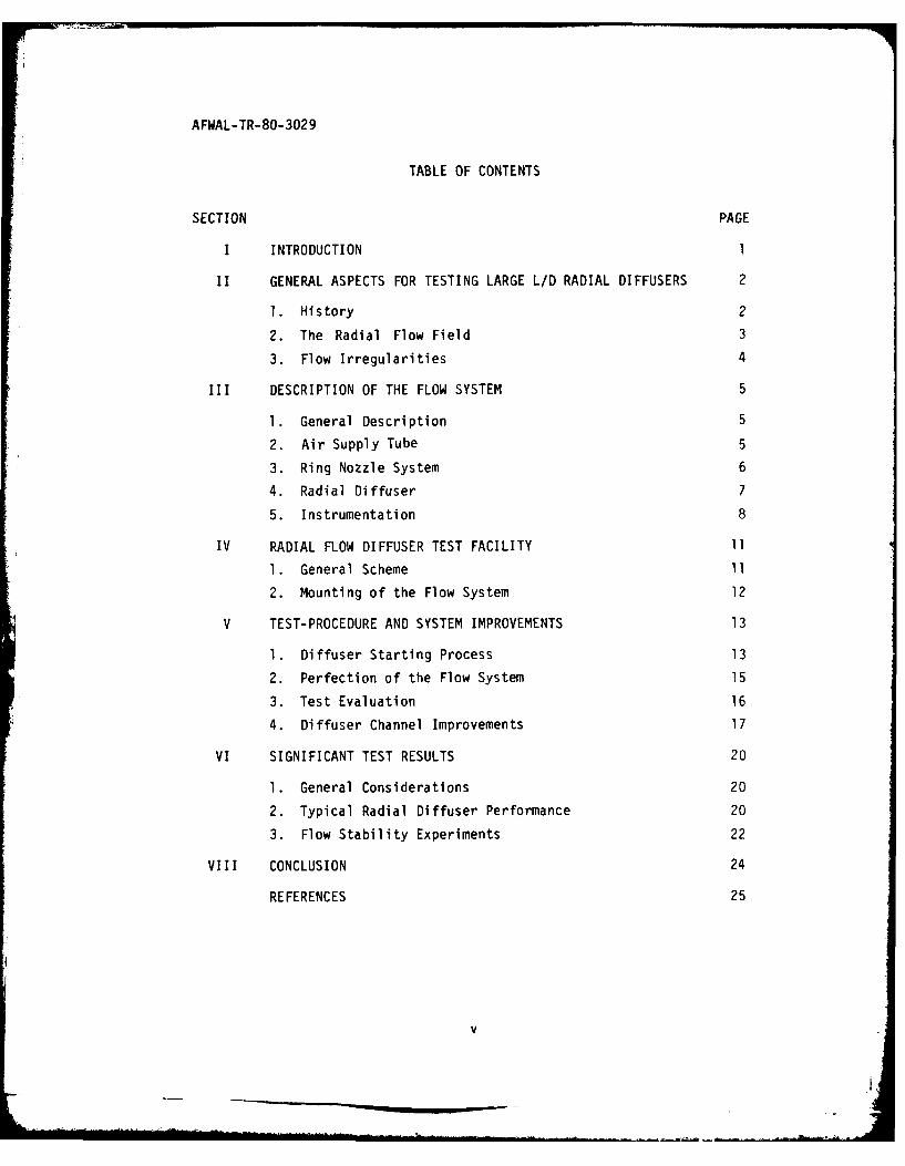
TABLE OF CONTENTS
SECTION PAGE
I INTRODUCTION 1
II GENERAL ASPECTS FOR TESTING LARGE L/D RADIAL DIFFUSERS 2
1. History 2
2. The Radial Flow Field 3
3. Flow Irregularities 4
III DESCRIPTION OF THE FLOW SYSTEM 5
1. General Description 5
2. Air Supply Tube 5
3. Ring Nozzle System 6
4. Radial Diffuser 7
5. Instrumentation 8
IV RADIAL FLOW DIFFUSER TEST FACILITY 11
1. General Scheme 11
2. Mounting of the Flow System 12
V TEST-PROCEDURE AND SYSTEM IMPROVEMENTS 13
1. Diffuser Starting Process 13
2. Perfection of the Flow System 15
3. Test Evaluation 16
4. Diffuser Channel Improvements 17
VI SIGNIFICANT TEST RESULTS 20
1. General Considerations 20
2. Typical Radial Diffuser Performance 20
3. Flow Stability Experiments 22
VIII CONCLUSION 24
REFERENCES 25
v
AFWAL-TR-80-3029
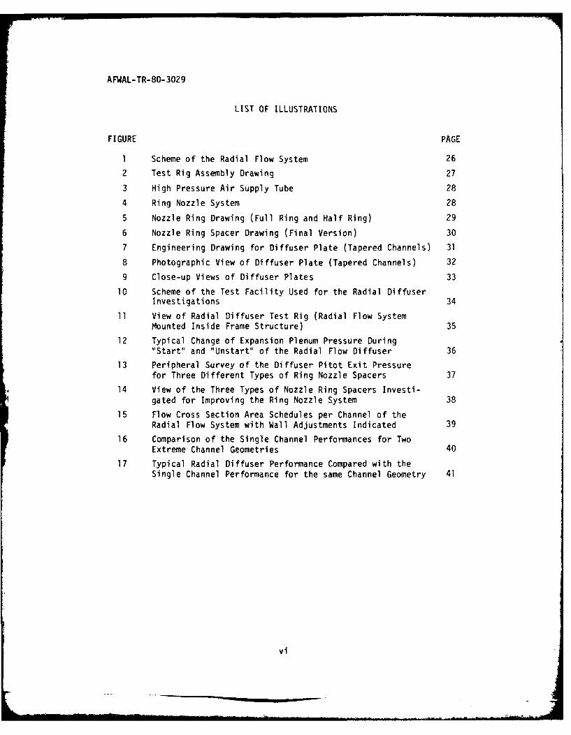
LIST OF ILLUSTRATIONS
FIGURE PAGE
1 Scheme of the Radial Flow System 26
2 Test Rig Assembly Drawing 27
3 High Pressure Air Supply Tube 28
4 Ring Nozzle System 28
5 Nozzle Ring Drawing (Full Ring and Half Ring) 29
6 Nozzle Ring Spacer Drawing (Final Version) 30
7 Engineering Drawing for Diffuser Plate (Tapered Channels) 31
8 Photographic View of Diffuser Plate (Tapered Channels) 32
9 Close-up Views of Diffuser Plates 33
10 Scheme of the Test Facility Used for the Radial DiffuserInvestigations 34
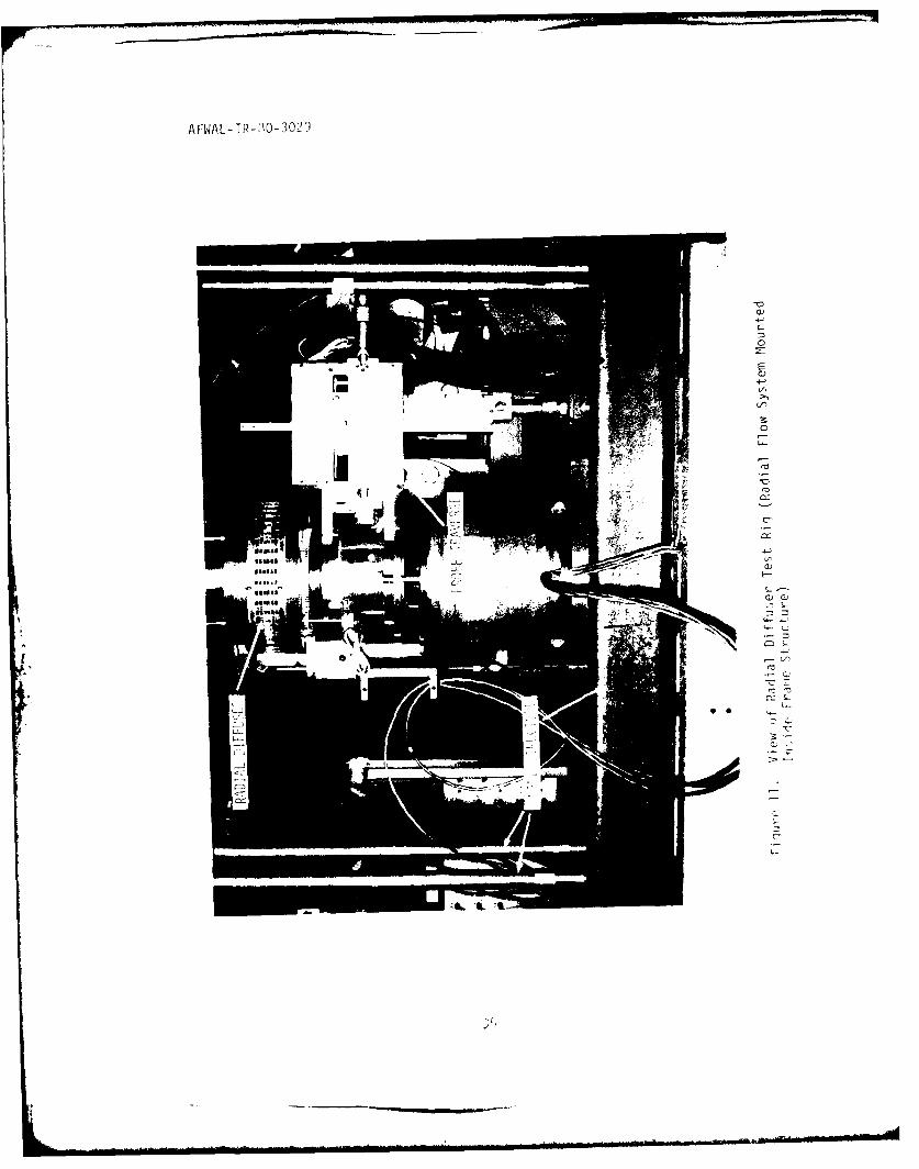
11 View of Radial Diffuser Test Rig (Radial Flow SystemMounted Inside Frame Structure) 35
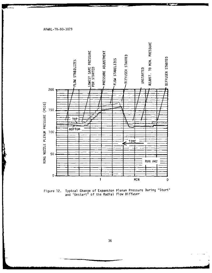
12 Typical Change of Expansion Plenum Pressure During"Start" and "Unstart" of the Radial Flow Diffuser 36
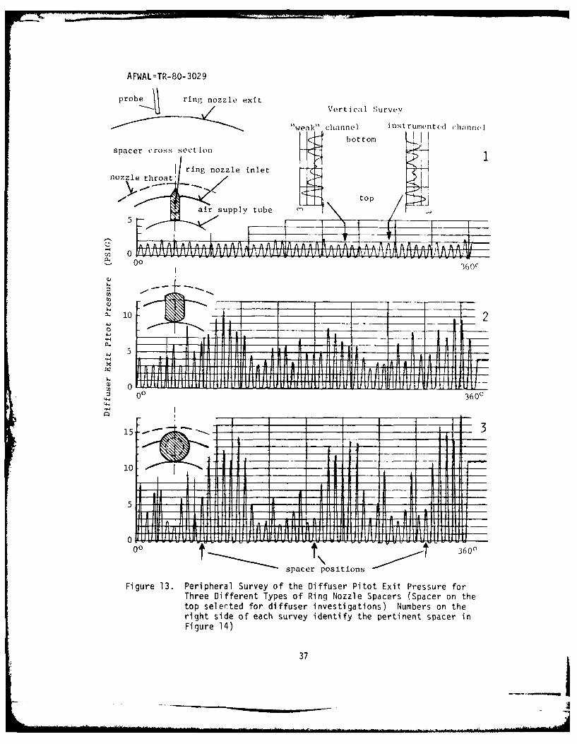
13 Peripheral Survey of the Diffuser Pitot Exit Pressurefor Three Different Types of Ring Nozzle Spacers 37
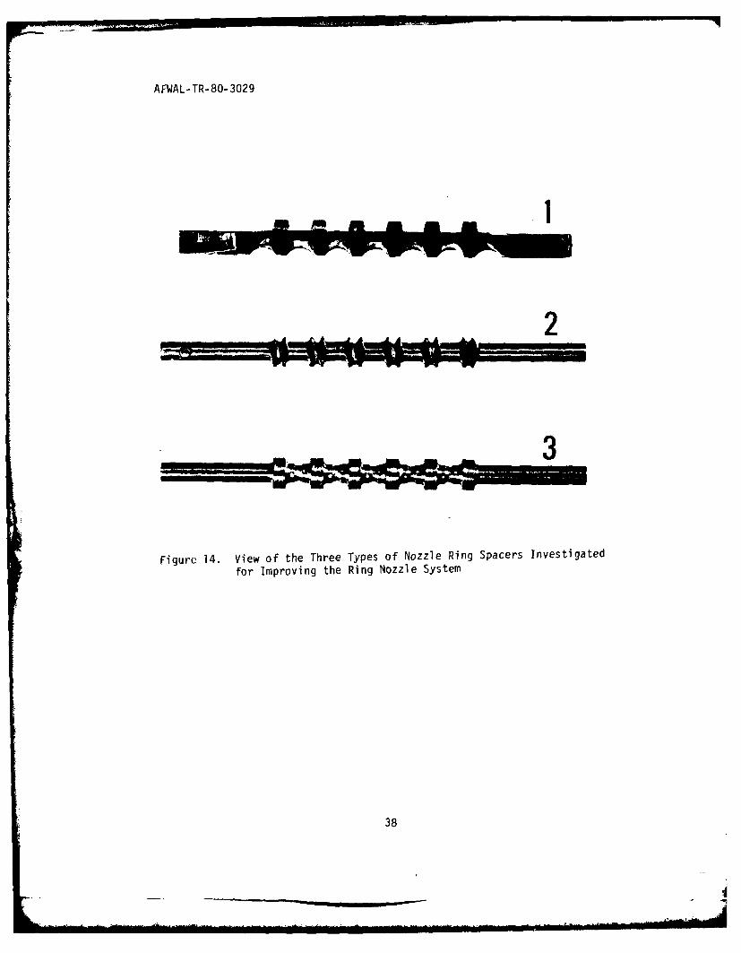
14 View of the Three Types of Nozzle Ring Spacers Investi-gated for Improving the Ring Nozzle System 38
15 Flow Cross Section Area Schedules per Channel of theRadial Flow System with Wall Adjustments Indicated 39
16 Comparison of the Single Channel Performances for TwoExtreme Channel Geometries 40
17 Typical Radial Diffuser Performance Compared with theSingle Channel Performance for the same Channel Geometry 41
vi
AFWAL-TR-80-3029
SECTION I
INTRODUCTION
The present investigations deal with an unusual type of diffuser,
even as far as radial flow diffusers are concerned. There is no generally
known supersonic radial diffuser. Even in the well known supersonic com-
pressor, shock diffusion takes place in the rotor while the flow in the
stationary diffuser is all subsonic. Its axial length-to-diameter (L/D)
ratio distinguishes the present diffuser in particular from any other kind
of radial flow diffuser. This ratio is many times larger than that commonly
encountered with radial flow diffusers.
The need for this new type of diffuser stems from the developmenc of
airborne high energy lasers using a radial flow system. Such lasers re-
quire an axial L/D ratio referred to the diffuser inlet, of the order of
three. Mach numbers of interest range from around three down to two.
Nozzle throat Reynolds numbers typical for real laser systems are in the
order of lO4 and lower.
Since the aim in the present cold flow experiments was to explore
the basic behavior of the radial flow diffuser, compliance with laser
flow conditions in all details was not considered necessary. For a first
approach, it was even desirable to minimize viscous effects and investigate
them separately. To simplify experimental conditions, L/D was also mini-
mized. Since a large Mach number accommodates the design of a radial flow
expansion system (Reference 5) an upper limit was chosen for this number.* O4
Resulting nominal figures for the test rig were: M = 3.5, Re = 510
and L/D = 0.5. For future explorations, the test rig had provisions to
extend the L/D up to 3. The expansion nozzle system was designed for
exchangeability with other nozzle systems. The complete test rig, which
includes a three coordinate probe traversing mechanism, was designed for
an eventual enclosure in a vacuum chamber for operation at lower pressure
levels to reduce flow Reynolds numbers.
1
AFWAL-TR-80-3029
SECTION II
GENERAL ASPECTS FOR TESTING LARGEL/D RADIAL DIFFUSERS
1. HISTORY
Early experiments with this new type of diffuser were carried out by
P. J. Ortwerth, et al (Reference 1). In this case, however, the L/D was
only approximately 0.12. J. Howard and S. Hasinger reported in Reference
2 about a radial flow diffuser with an L/D increased to about 0.6. This
diffuser was in axial as well as peripheral direction subdivided in a
multitude of small channels ("egg-crate diffuser"). It was of a makeshift
design and accomplished only 50% of normal shock recovery. It is the
forerunner of the present diffuser, which is of the same type but fabricated
more precisely and somewhat larger in absolute size. Its L/D is about
0.5, a value considered sufficiently large to determine the characteristic
behavior of radial diffusers with a minimum of experimental complexities.
Professor J. Lee at Ohio State University has investigated a vaneless
radial diffuser featuring contoured side walls to provide a near c nstant
area flow passage for the diffusing flow (Reference 3). Without any sub-
division of the flow, this type diffuser is restricted to comparatively
small L/D values.
A radial flow diffuser subdivided only in peripheral direction by
axially directed vanes has been investigated by United Technology Research
Center, East Hartford, Connecticut;(Reference 4). The L/D of this diffuser
is approximately 1.2. With this L/D value, the peripheral subdivision
results in diffuser channels with a very high aspect ratio, i.e., the
dimensions of the channel cross section are much larger in axial than in
peripheral direction. This diffuser needs boundary layer energization
at the diffuser endwalls for starting and maintaining a diffusing flow.
The incentive for applying this type of vanes is the ease with which they
can be fitted with cooling channels, a necessity for the actual laser
application.
2
AFWAL-TR-80-3029
The present multi-channel diffuser is not readily adaptable to cooling.
However, for the purpose of the present investigations it has the advantage
of being quite adaptable to the fluid-dynamic needs for optimizing the
diffuser performance. Results from the present investigations should be
helpful for improving other diffuser types; in particular, the last one
mentioned in respect to eliminating or reducing its need for boundary
layer energization.
2. THE RADIAL FLOW FIELD
The present diffuser investigations are not only characterized by
dealing with a unique flow field but also by fundamental difficulties in
providing this flow field. This is due to the geometric constraints
imposed on the flow source by the requirement for a large L/D. The
restrictions are particularly severe for lower Mach numbers, say below
4, such as applicable here. Their severity depends also on operating
conditions and the operating medium (Reference 5). The restrictions are
more severe for the cold flow conditions used here than in the actual
laser. The flow source developed here is therefore not necessarily
typical for the actual laser system.
The need to utilize a multitude of expansion nozzles to produce the
desired flow field is common to all large L/D radial flow systems. The exit
flow of such systems inherently contains wakes produced by the individual
nozzle walls. These wakes originate as boundary layers on the nozzle walls
and are augmented by the sudden cross sectional area increase at the nozzle
exits due to the finite thickness of the exit edges of the nozzles. Because
of these flow disturbances, the expansion exit conditions can no longer be
derived from simple potential flow considerations. Thus, the diffuser inlet
flow given by the expansion in the ring nozzles and the subsequent expansion
in the cavity between the nozzle system and the diffuser must either be
determined experimentally or by analysis including all expansion losses.
The present test arrangement does not allow an experimental determination
since the expansion nozzles because of the radial arrangement of the flow system,
are not accessible to a flow survey with the diffuser in place and they
3
AFWAL-TR-80-3029
cannot be operated at design conditions with the diffuser removed. It
was therefore necessary to determine the expansion nozzle performance
analytically. This effort is reported in Reference 5. Its result, in
the form of an effective diffuser inlet Mach number, is the basis for
evaluating the test results with the present diffuser.
3. FLOW IRREGULARITIES
In addition to the flow disturbances given by the wakes of the
nozzle walls, the geometric constraints of the radial expansion system
are also responsible for flow irregularities which originate in the
nozzle inlet region in connection with the nozzle support structure.
These additional flow disturbances, which can have a very serious
influence on the diffuser performance, cannot be completely eliminated
and a considerable portion of the present effort was devoted to the
attempt to minimize them.
4
AFWAL-TR-80-3029
SECTION III
DESCRIPTION OF THE FLOW SYSTEM
1. GENERAL DESCRIPTION
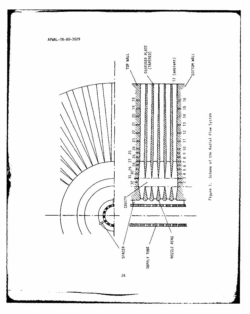
Figure 1 gives a schematic view of a cut through the complete radial
flow system. It consists of a high pressure air supply tube, the expansion
nozzle system consisting of a series of "ring nozzle," and the radial
diffuser made up of a system of "diffuser plates." The space between the
nozzle exits and the diffuser constitutes the "cavity" where the laser
process takes place in the real system. Each of the end walls designated
in Figure 1 with "top" and "bottom" according to their position in the test
rig is provided with a row of port holes for measuring the static pressure
distribution along one diffuser channel each on the top and bottom wall.
The numbers assigned to the port holes are used for reference in the
experiments. In the following, each element of the flow system is described
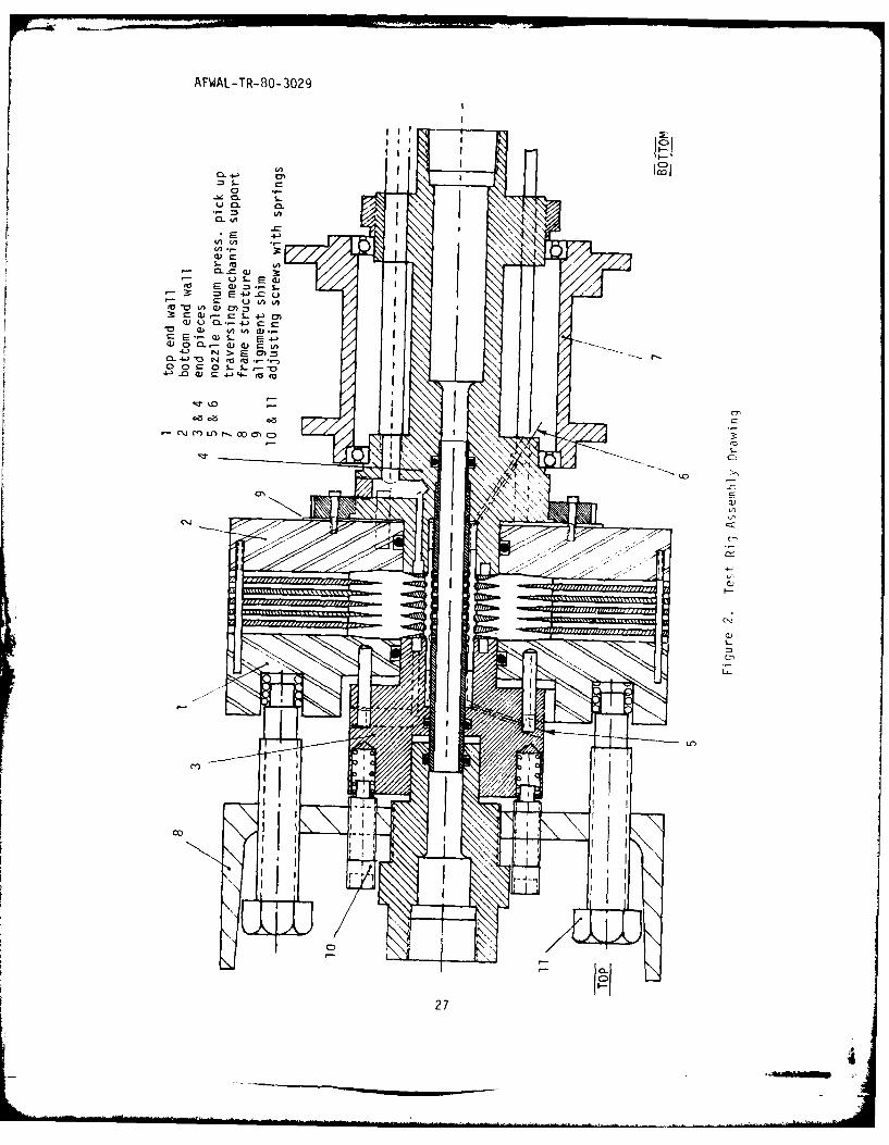
in more details. For this description, reference is also made to FigurE 2
which gives an assembly drawing of the radial flow system, including the
support structure for the probe-traversing mechanism. The probe system
itself is described at the end of this Section.
2. AIR SUPPLY TUBE
The supply tube supplies the incoming air uniformly along the axis of
the flow system. It carries air of typically about 900 psig. Due to this
high pressure, the inlet velocity of the air to the tube at both ends is
very low (M = 0.4). The flow is throttled through the tube perforations
to the pressure level prevailing ahead of the expansion nozzle system.
Due to the limited space available between supply tube and nozzle inlet,
the kinetic energy of the air expanding through the perforations cannot
fully be dispersed. To obtain at least a random kinetic energy distri-
bution, the flow is made to impact on the inside surface of the nozzle
rings. Some dispersion of the flow is also obtained by the perforations
being arranged inside the grooves, which should promote peripheral dis-
persion. Figure 3 gives a photograph of the supply tube.
5
AFWAL-TR-80-3029
3. RING NOZZLE SYSTEM
The radial flow admitted to the radial diffuser is generated in the
expansion system which consists of a series of axially arranged rings as
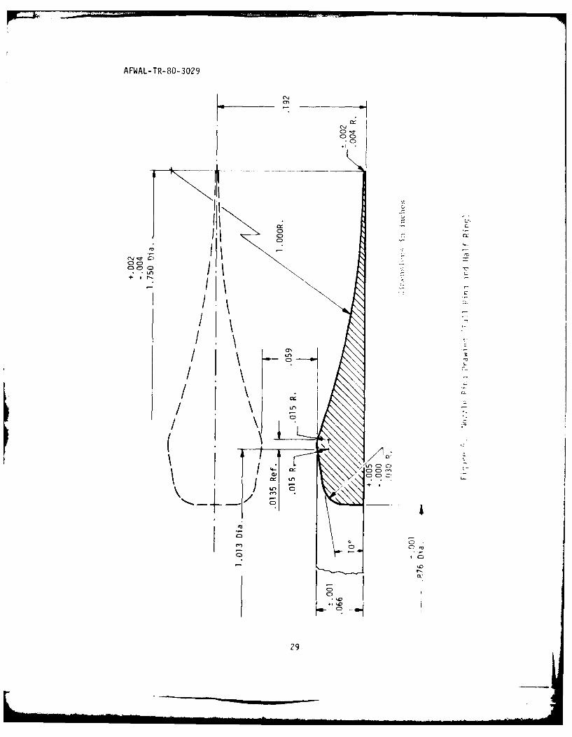
shown in Figure 4. Figure 5 is an engineering drawing of a nozzle ring
together with a half ring needed at the ends of the nozzle system. The
nozzle rings are kept centered and axially spaced by three spacer elements
located 1200 apart between the supply tube and the ring nozzles. One of the
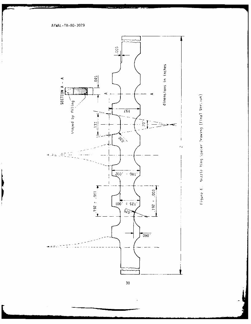
spacers is partially visible in Figure 4. Figure 6 is an engineering
drawing for a spacer blank. For streamlining this blank it was shaped
as outlined in the cross section A - A by hand filing. This spacer design
permitted a very precise machining of the spacing dimensions and provided
rigidity with a minimum of flow disturbance.
The nozzle ring spacers proved to be one of the most critical elements
for the flow system design because of their influence on the diffuser
performance. More details on the development of the present spacer are
given in Section V.
The spacers function in the following way. The full size nozzle
rings are held in place by the spacer grooves as indicated in Figure 6.
The half rings are positioned at the ends of the spacers, as also shown
in Figure 6. They are held in place together with the entire nozzle ring
assembly by the two end pieces of the mounting system (Figure 2). The
mounting forces are transmitted over the end pieces to the outside frame
structure via springs and adjusting screws seen in Figure 2as the smaller
ones of two sets of springs and adjusting screws. The larger set holds
the diffuser package together as described below. To prevent indentation
of the nozzle rings or deformation of the spacers, they were made of 17-4PH
stainless steel and hardened tool steel respectively. The following
procedure was used to give the full size nozzle rings a tight seat. The
dimension of the nozzle ring where it sits in the spacer groove was made
slightly oversize (0.001"). At three locations 1200 apart this oversize
dimension was made slightly undersize (:O.OOl"). The rings were mounted
first with their undersize portions in the spacer grooves. For tightening,
they were then rotated to engage the oversize portion of the ring seats
6
AFWAL-TR-80-3029
in the spacer grooves until they were sufficiently tight. To assure this
engagement, a very small amount of Eastman 910-type glue was added at the
contact points between the rings and the spacers. This system proved to
be very reliable. The accuracy of the radial as well as the axial spacing
of the nozzle rings is estimated to have been within ±0.002".
The expansion system also incorporated adjustable ring slots at both
cavity side walls for injecting high pressure air to energize the wall
boundary layers. These slots are formed by the back walls of the half
nozzle rings and the end pieces holding the nozzle system in place. In
Figure 2, the plenum chambers feeding the ring slots can be seen next to
the half ring nozzles. In the present investigations, boundary layer
injection was only used inan exploratory way and no results of particular
consequence were obtained. None of the experiments reported here involves
boundary layer injection.
A detailed flow analysis of the present ring nozzle system is given
in Reference 5. It calculated an effective exit Mach number for the nozzle
system of M = 3.102. For isentropic expansion in this nozzle system, a
Mach number of M = 3.23 would be obtained. With the inclusion of the flow
expansion in the cavity between nozzle exits and diffuser inlet cunsiderin.
also flow losses, the analysis of Reference 5 finds an effective Mach wjirnhe,
of M = 3.514. This Mach number is the effective inlet Mach number of the
radial diffuser.
4. RADIAL DIFFUSER
The radial diffuser is made up of a series of ring plates into which
the individual diffuser channels have been cut by milling. The inoer
edges of these plates effect the axial subdivision ut the flow while ,:
pie shaped vanes (Figure 1) subdivide the flow in peripheral direction.
Figure 7 presents an engineering drawing of the diffuser plates in their
two forms necessary for assembling a complete diffuser package. 1o plo-vid
axial symmetry for the diffuser package, the plate in the miiddle of the
package has channels milled on both sides as shown in Figure 7 as No. 2
plate. All other plates of the package are No. 1 plates. Two sets ot
7
AFWAL-TR-80-3029
diffuser plates were fabricated, one with a constant area channel geometry
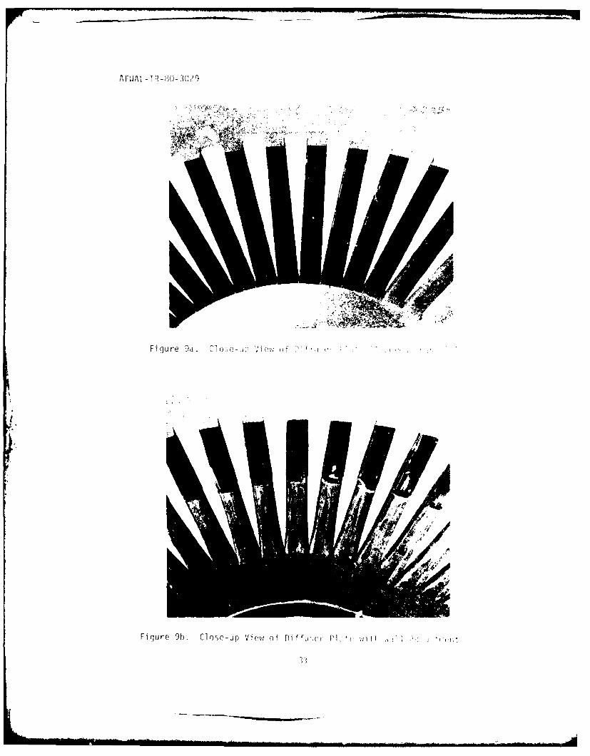
and the other with a 0.9' taper as shown in Figure 7. Figure 8 shows an
overall view and Figure 9 detail views of diffuser plates.
In subdividing any supersonic diffuser into small channels, the super-
sonic flow prevailing ahead of the throat should be exposed to a minimum
of wall surface, i.e., the subdivision should be limited as much as possible
to the diffuser portion downstream of the throat. This principle has been
applied in Reference 6 to a straight flow, two-dimensional diffuser duct
with a high aspect ratio. In this case it was shown that shock diffusion
requires a near axisymmetric duct cross section to be completely effective.
The diffuser plates shown here provided basic channel shapes which
could be changed by means of epoxy buildups. In this way, the inlet
cross section contour and the diffuser throat dimensions were changed.
These modifications are described in detail in Section V.
The diffuser package is mounted between the endwalls readily seen in
Figure 2. Springs press the left end wall against the diffuser package.
These springs had to be kept under very high tension to keep the diffuser
plates from vibrating under the influence of the diffusing flow.
5. INSTRUMENTATION
a. Static Wall Pressure
To survey the flow in the test rig, the expansion plenum pressure,the
cavity and diffuser wall pressures, and the exit pitot pressure of the
diffuser could be measured. In addition, the flow rate and the pressure
of the air supplied to the test rig could be recorded. Of these measurements,
only the static wall pressures and the pitot exit pressure were essential
for the test evaluation. Of these essential measurements, only the static
pressure reading for the diffuser inlet (wall pressure tap #4 and #30)
required a high degree of accuracy. The diffuser inlet pressure, together
with the barometric pressure representing the diffuser exit pressure,
determine the performance of the diffuser. Of the 288 individual diffuser
8
AFWAL-TR-80-3029
channels which make up the radial diffuser, the flow in only two channels,
one on each end wall, could be surveyed by a row of 15 static pressure
taps provided in the diffuser end walls (Figure 1). Both instrumented
channels were at the same peripheral location and the ring nozzle system
was always arranged in such a way that the ring nozzle spacers were
positioned peripherally as much as possible away from the instrumented
channels assuring a minimum disturbance of these channels by the spacers.
The accuracy with which the diffuser wall pressures could be determined
was somewhat limited. These pressures were found as the difference of the
barometric pressure and the suction pressure measured at the wall port hole.
This suction pressure could be determined within an accuracy of approximately
one third of one percent. Since the absolute wall pressure at the diffuser
inlet was roughly one tenth of the measured suction pressure, the absolute
wall pressure at the diffuser inlet could be obtained only with an accuracy
of about 3%. Correspondingly, diffuser performance values given in terms
of the percentage of normal shock pressure recovery can only be accurate
to a similar degree. For the purpose of the present investigations, which
was the determination of the general flow behavior of the radial diffuser,
this accuracy was considered sufficient.
All other measurements were needed for qualitative observations only.
The static wall pressure survey indicated the position of the shock system
in the diffuser and the exit pitot pressure survey gave information about
the peripheral uniformity of the flow, a factor which proved quite influential
for the diffuser flow behavior.
b. Expansion Process
A flow survey of the expansion process was not possible as
previously mentioned, but it was also not needed, since its performance
could be determined analytically with sufficient accuracy. The measure-
ments for the static pressure ahead of the nozzle system were very
unreliable, since strong recirculating flows in the nozzle plenum area
prevented exact static pressure measurements. Experience showed that
such pressure measurements depended, for instance, on the arrangement of
9
AFWAL-TR-80-3029
the holes in the supply tube perforation. Reducing the hole size of the
end rows of the perforation by about 30% in an earlier supply tube con-
figuration which originally had uniform hole sizes (0.075 inches), reduced
the static pressure reading for the nozzle plenum by about 10% however with
no noticeable effect on the diffuser performance. The effect on the
pressure reading may be explained in the following way. In the case of
uniform size holes in the supply tube, the end nozzles receive an over-
supply of air which leads to recirculation in the end portion of the
nozzle plenum where the static pressure pick-ups are located (Figure 2).
Since the flow coming from the supply tube is allowed to impinge on the
inner nozzle ring wall, comparatively strong axial flow components may
exist in the plenum; whereas radial flow components which affect the flow
in the nozzles may be greatly attenuated. Because of the strong expansion
of the flow in the nozzles, large flow irregularities can be tolerated
upstream of the nozzles. The Mach number of the average radial flow
component ahead of the nozzles is about 0.15. A 100% variation in this
component can only cause a dynamic pressure variation in the expansion
process which leads to an expansion Mach number variation of P., not
taking into account any smoothing out of the flow during expansion. As
further proof for the relative independence of the nozzle downstream
conditions from the upstream flow irregularities is the negligible effect
which the switch from a large hole to a small hole supply tube (Figure 3)
had on the diffuser performance.
c. Traversing Mechanism
An important tool for the investigations proved to be the probe-
traversing mechanism which allowed radial, axial, and peripheral movement
of a probe for surveying the diffuser exit flow. Its main use was checking
for the uniformity of the diffuser exit flow under the influence of non-
uniformities in the inlet flow. An important alternate use of the traversing
mechanism was the flow control of individual channels by means of a blocking
body held in place and controlled by the traversing mechanism. A particularly
useful function in this respect was moving the blocking body at a distinct
setting from channel to channel around the periphery of the diffuser to
check the performance limit of individual channels. (Section VI).
10
AFWAL-TR-80-3029
SECTION IV
RADIAL FLOW DIFFUSER TEST FACILITY
1. GENERAL SCHEME
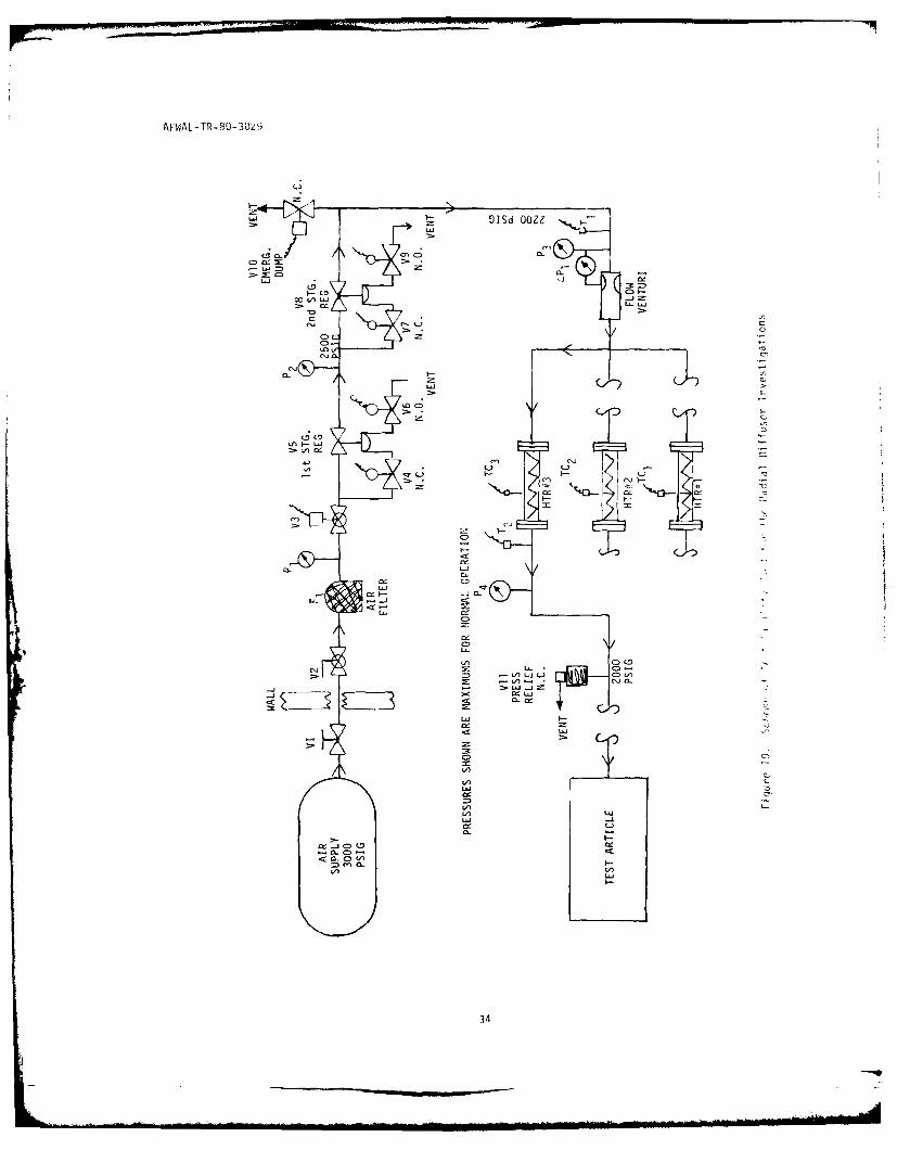
A flow schematic of the facility for testing the Radial Flow Diffuser
is shown in Figure 10. The entire flow chart may be grouped into three
systems; the air supply, air regulation, and test apparatus. The air
supply system consists of high pressure air (3000 psig) storage vessels,
associated plumbing, and controls. The air regulation system consists of
a two-stage pressure reduction regulating system, a two micron air filter,
a mass flow venturi, assorted control valves, solenoid, pressure/temperature
sensing elements, and three 80KW input electrical resistance heaters with
associated controls and instrumentation. The test apparatus consists of
the radial outflow system with diffuser assembly, a pressure probe
traversing mechanism, associated pressure and temperature pick ups, and
a calibration system.
All pressure measurements were recorded on a 12 channel strip chart
recording system manufactured by S. Sterling Company. Each channel has
individual balance, span, polarity reversal, and electrical calibration
controls. The transducer signals are fed to three dual channel Texas
Instrument Company Servo-Writer Mark II recorders mounted in the S. Sterling
Company instrument cabinet. Six channels of information can be permanently
recorded through a 12 channel switching matrix with an overall system
accuracy of ±0.25% or ±5 micro-volts, whichever is greater.
The Radial Outflow Diffuser static wall pressures, both top and
bottom, were sensed through a 48 channel Scanivalve pneumatic scanner,
M/N SSS-48CBM/1248BCD/SLSN, using a 15 psid Statham differential pressure
transducer, M/N PL131TC-15-350, whose output was recorded on the Texas
Instrument Company Servo-Writer Mark II recorder.
Barometric pressure was measured on a Princo Instrument Inc., U.S.
Signal Corps Tartan-type mercurial barometer before and after each test
run as required.
11
AFWAL-TR-80-3029
Supply air temperature was measured with a 3/32" diameter Iron-
constantan fast response thermocouple, manufactured by the Conax Company,
and read out on a Sym-ply-trol pyrometer mounted on the operator's control
panel.
Each data acquisition system was calibrated end-to-end before and
after each test run. Pressure systems were calibrated against a laboratory
precision Heise pressure gage or a 30 inch mercury manometer, depending on
the absolute pressure levels encountered. Thermocouples were calibrated
in an ice-water bath and in a laboratory single wall transite oven, manu-
factured by Blue M Electric Company, M/N SW-17-TA. The test points were
32°F and 400'F respectively, as indicated by a precision laboratory
thermometer.
The typical supply air temperature for the test rig was 750F.
2. MOUNTING OF THE FLOW SYSTEM
The radial flow system, together with the probe traversing mechanism,
were mounted inside a special frame structure which can be seen in part
in the photograph shown in Figure 11. The purpose of the frame structure
was to take up all forces acting on the test rig in axial direction. The
high pressure air supply tube was mounted floating in one of the end
pieces of the flow system (Figure 2) and the air pressure forces in axial
direction had to be taken up by the frame structure. The ring nozzle
system and the diffuser package were held in place independently of each
other by spring tension transmitted to the frame structure by springs and
adjusting screws. This construction eliminated all danger of internal
stresses due to temperature differences produced by Joule-Thompson cooling
during the air expansion process.
The probe traversing mechanism could freely move inside the frame
structure for surveying the diffuser package in peripheral, axial, and
radial direction. Traversing speeds could be varied from about 2 to 10
inches per minute.
12
AFWAL-TR-80-3029
SECTION V
TEST PROCEDURE AND SYSTEM IMPROVEMENTS
1. DIFFUSER STARTING PROCESS
As with any supersonic diffuser, the radial flow diffuser must be
started to reach its operational state. For the starting process, the
pressure difference across the shock system which establishes itself in
the cavity must be reduced. This allows the flow momentum forces to push
the shock system downstream into the diffuser. In entering the diffuser,
the shock system is able to provide better pressure recovery, increasing
also the flow momentum forces which push the shock system further downstream
toward the diffuser exit. Under this condition, a substantial portion of
the diffuser walls is exposed to supersonic flow and thereby incurring
flow losses. By increasing the pressure difference across the shock
system, the flow pressure forces push the shock system again upstream
toward the diffuser inlet with an increase in shock recovery ratio due
to the reduction of wall flow losses. If the pressure difference is
increased too much, the shock system is pushed out of the diffuser and
the diffuser becomesunstarted. Since in the present experiments, the
diffuser discharges to ambient, i.e. the diffuser exit pressure remains
constant the diffuser-starting process is controlled entirely by the
upstream expansion pressure. Figure 12 gives a typical plot of the ring
nozzle plenum pressure during start and unstart of the present diffuser.
The common picture of the diffuser starting process given above needs
some amplification for the case of the radial flow diffuser. In the
starting process, the stick system to be pushed into the diffuser has a
very specific shape in the present case. Experimental evidence given in
Reference 2 shows that the flow expanding in a ring nozzle system forms a
well defined barrel-like shock front surrounding the nozzle system. The
diameter of the barrel depends on the expansion pressure ratio. Increasing
the pressure ratio makes the barrel grow. Reference 2 found a value of
about 40", of normal shock recovery for the pressure recovery across this
barrel shock front. As indicated in Reference 2, this shock front which
has the appearance of a normal shock, is actually made up of a series of
13
AFWAL-TR-80-3029
oblique shocks formed between the wakes coming off the individual nozzle
rings of the expansion system.
If the ring nozzle system is surrounded at some distance by a radial
flow diffuser, the shock front, due to its barrel-like shape, reaches the
center portion of the diffuser during the starting process before it
reaches the portion near the end walls. Thus, the diffuser can only be
started if the entire shock front reaches the diffuser.
For the operation of the multi-channel radial diffuser, a phenomenon
observed during the investigations reported in Reference 2 is of particular
significance here. When a piece of a small straight tube is immersed into
the barrel shock, this tube by itself acts as a suction device since the
supersonic flow entering the tube experiences a better pressure recovery
inside the tube than across the barrel shock. Thus, diffusion can be
improved locally in the flow system by placing diffuser channels into the
flow where improvement is needed. Reference 2 reports some experiments
with a wall diffuser. In this case, a single diffuser plate, the kind used
here,(Figure 7) was placed on each end wall with the remaining portion of
the radial flow passage left open. Due to the suction effect of these
wall diffusers, the barrel shock remaining between the wall diffusers
assumed a nearly cylindrical shape. Although the recovery rate was not
improved, the result was a fairly uniform radial flow in the cavity.
In case of the present multi-channel diffuser, the channels in the
middle of the diffuser package become started apparently before the end
wall channels. The degree to which the started center channels support
the starting of the end wall channels has so far not been determined.
Present experimental experience has shown that starting the multi-channel
diffuser, as far as pushing the shock system into the diffuser is concerned,
rjenerally occurs as a sidden event marked by a distinct reduction in flow
noise. However,ithen the expansion supply pressure was raised very slowly,
intermediate steps of starting could be distinguished. In contrast,
unstart of the diffuser by lowering the supply pressure invariably
occurred as a sudden conversion to fully unstarted conditions. In some
rare cases, recovery from a beginning unstart to fully started condition
14
AFFDL-TR-80-3029
has been observed. For practical purposes, start and unstart of the
diffuser were very distinct and reproducible events in terms of the
required expansion pressure.
For the start and unstart behavior of a multi-channel diffuser, the
weak channel effect must be taken into account. In starting the diffuser,
a deficient performance of a single channel can be readily overcome by the
good performance of the rest of the channels since, as we have seen from
the single tube diffuser, channels can be started without being affected
by their neighborhood flow conditions. The conditions are reversed for
the unstart process where the shock systems are in all channels more or
less positioned closely to the diffuser inlets. A single unstarted
channel can precipitate an unstart process in its neighborhood and subse-
quently in the entire diffuser. Thus, the weakest channel should determine
the overall diffuser performance (Section VI). A local disturbance in the
source flow is equivalent to a weak channel. This was the prevalent case
in the present flow system. As already pointed out, the system was inflicted
with inherent non-uniformities, and a special effort had to be made as
described in the next paragraph, to minimize these deficiencies.
2. PERFECTION OF THE FLOW SYSTEM
a. Flow Channel Alignment
An adjustment of the channel walls for the transition from the
end nozzle rings (half rings) to the cavity wall was necessary. As
described in Section III, the relative positions of these two elements
were adjustable to form, if necessary, a boundary layer injection slot.
For the present tests which do not employ boundary layer injection, this
slot was closed in such a way that the back side of the half ring was
made to line up with the cavity wall as close as possible. Because of
the finite thickness of the half ring exit edge, there was a nominal step
of 0.005" enlarging the flow path at this point. This adjustment was
accomplished by shims placed underneath the support of the bottom end
wall (Figure 2). It also necessitated a slight increase in the height of
the diffuser plate package. This wr done by gluing thin paper (zO.002")
on each plate. The alignment could be checked on the assembled system by
a special gage inserted through the diffuser channels on the end walls.
15
AFWAL-TR-80-3029
b. Elimination of Peripheral Flow Irregularities
As mentioned before, the nozzle ring spacers were a principal
cause for flow disturbances. In Figure 13, the pitot exit pressure of
the diffuser was surveyed over the full circumference of one of the
diffuser plates for three different types of spacers. These spacers are
located 1200 apart in the space between the high pressure air supply tube
and the nozzle rings as described in Section III. Figure 14 gives a
photograph of the three different types of spacers used in the survey.
For the sheet-type spacer which was finally adopted for the diffuser
experiments, an engineering drawing was already shown in Figure 6. The
dimensional differences between the three types of spacers occur only in
peripheral direction, i.e., their contours as viewed in peripheral direction
do not change. Their radial extension was such that they did not reach
into the ring nozzle throats (Figure 6).
The round type spacer used in the survey shown at the bottom of
Figure 13 produced unexpectedly large disturbance. In this case, the
flow in some of the channels located between the spacer positions is
still supersonic. All surveys were made for the diffuser in started
conditions. For the next spacer type with the sides flattened, the flow
uniformity is improved; but the diffuser exit flow is still greatly
disturbed, though no supersonic flows appear. For the sheet type spacer,
the conditions are drastically improved as shown in the top survey. No
influence of the spacers on the exit flow becomes apparent. For this
spacer type, two axial surveys are also shown along the diffuser package.
The flow fluctuations in this direction are somewhat larger than those
found for the peripheral survey. Because of the generally good results
with the sheet type spacer, no further attempts to improve the spacers
were considered necessary.
3. TEST EVALUATION
To generalize the test results obtained in the form of diffuser
wall pressure distributions, the measured pressures were related to the
normal shock performance of the diffuser given by the diffuser inlet Mach
number. The value of this Mach number is 3.514 as analytically determined
16
AFWAL-TR-80-3029
in Reference 5. The shock recovery ratio for this Mach number is 14.24
as given by common supersonic flow relations. The reference pressure for
making measured pressures dimensionless is the diffuser exit pressure
which would be obtained with normal shock recovery, i.e., the measured
diffuser inlet pressure (pressure tap No. 3 or 31 in Figure 1) multiplied
by 14.24 gives the reference pressure by which all measured values are to
be divided. If the reference pressure is equal to the ambient pressure,
which is always the diffuser exit pressure by design, pressure recovery
is 100" of normal shock recovery.
4. DIFFUSER CHANNEL IMPROVEMENTS
The diffuser plates, as described in Section III, were designed with
the intention of making small but critical flow cross section adjustments
by means of epoxy layer buildups on the diffuser walls. With this in mind,
the diffuser plates were fabricated with a moderate throat contraction of
0.86 (cross-sectional area ratio of throat to diffuser inlet) to assure
starting of the diffuser in any case. The minimum theoretical contraction ratin
is 0.69 for the Mach number prevailing here. Since the diffuser performance
generally improves with increasing throat contraction up to the limit
given by the diffuser starting conditions, wall adjustments of the
fabricated plates were made to increase the contraction of the throat
section. Another adjustment proved to be necessary for the diffuser
plate inlet edges. In a radial flow system, a straight wedge profile
produces a cross-sectional area reduction from inlet to throat which is
similar to that of an inverted supersonic nozzle for parallel exit flow.
This apparently ideal shape caused a delay in the onset of diffusion with
otherwise no beneficial effects. A kind of ramp was built up by epoxy
plastic on one side of the inlet edge to produce a near constant rate of
area reduction in the diffuser inlet region ahead of the throat.
Figure 15 gives an account of all wall contour adjustments made to
diffuser channels. In this figure, the flow cross-sectional area of the
flow for one diffuser channel is plotted over the radius of the flow
system for the various wall adjustments. The solid lines represent the
conditions for the machined parts of the system. All other lines refer
17
AFWAL-TR-80-3029
to wall adjustments made by means of epoxy layer buildups. These adjust-
ments were not always applied to the complete diffuser system. Instead,
either the channels of one plate or only a few channels of one plate were
fitted with these adjustments. One of the adjusted channels was always
an instrumented one. As indicated in Section III the present test ar-
rangement allowed throttling individual diffuser channels for checking
whether a particular channel is capable of a higher pressure recovery
than the radial diffuser as a whole was able to achieve. By throttling
the instrumented channel, a quantitative performance comparison could be
made for the various adjustments. The adjustment indicated in Figure 15
by the heavy dashed line was finally selected as particularly promising
for applying to the complete diffuser, i.e., to all 288 channels of the
system. The diffuser performance obtained with this optimized arrangement
is described in Section VI. Experimental results about the influence of
the channel geometry on the performance of a single channel in the radial
diffuser are discussed in the following paragraphs.
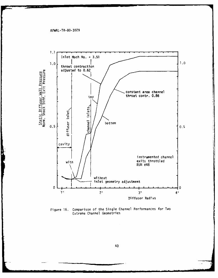
The experiments showed that the diffuser performance is not particularly
sensitive to the various channel adjustments. An example which presents
typical upper and lower performance limits for the applied adjustments as
found in single channel testing is shown in Figure 16. In this case, the
diffuser package consisted of unmodified plates with constant area diffuser
channels except for the top plate which was the same machined plate but
had the throats adjusted for a contraction ratio of 0.75. A group of five
channels on this plate, with the middle one instrumented, were modified
to a throat contraction ratio of 0.62, which is below the min;mum theoretical
value (line 2 in Figure 15). In Figure 16, the performances of the two
instrumented channels in this diffuser package, one channel unmodified
with throat contraction 0.86, the other with contraction 0.62, are com-
pared. The performances are plotted in terms of the percentage of normal
shock recovery over the radius of cavity and diffuser (Section V). The
unmodified channel with a throat contraction of 0.86 (constant area channel)
reaches already 94% normal shock recovery, while with throat contraction
of 0.62 the recovery ratio goes up to 107%. This is very close to the
best single channel performance obtained in any of the present investigations
18
AFWAL-TR-80-3029
(Section VI). This good performance is of interest in connection with the
prediction made in Reference 5, namely that a diffuser channel with a
contraction followed by a short divergence changing into a constant area
channel as applicable to line 2 of Figure 15 should yield favorable
recovery ratios.
Figure 16 demonstrates the influence of the diffuser inlet edge
adjustment described above. For the upper curve in Figure 16, one side of
the inlet edge is recontoured as indicated in Figure 15 for curves 1 to 4.
The lower curve in Figure 16 represents the pressure rise for the unmodified
diffuser plate. For the adjusted inlet contour, the pressure rise begins
earlier than in the case of the unadjusted diffuser plate. This earlier
rise is advantageous since it reduces wall friction.
19
AFWAL-TR-80-3029
SECTION VI
SIGNIFICANT TEST RESULTS
1. GENERAL CONSIDERATIONS
At the beginning of the investigations, optimizing the diffuser
channel geometry was considered the principal problem for perfecting the
radial flow diffuser. However, during preliminary testing, it became
apparent that deficiencies in the uniformity of the source flow had an
overriding influence on the diffuser performance. The attempt to eliminate
disturbances in the source flow as described in the previous Section to a
degree that there would be no significant effect on the diffuser performance
was not successful. The need for spacers to keep the ring nozzles in
position makes the establishment of uniform peripheral flow conditions
inherently difficult. A principal difficulty with diffusers is that the
diffusing flow quite generally has a tendency to become unstable with
increasing pressure recovery indicating that a diffuser has the tendency
to amplify incoming flow disturbances rather than to smooth them out.
Thus, flow stabi)ity rather than channel geometry appeared as the major
problem in perfecting the present diffuser.
Single channel testing as described in the previous Section provided
the means to separate effects on the diffuser pprformance caused by faulty
channel geometry from those originating from a lack of flow stability.
2. TYPICAL RADIAL DIFFUSER PERFORMANCE
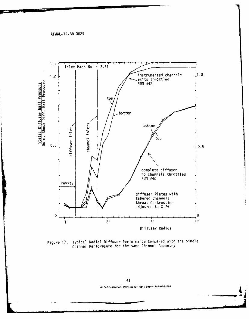
The diffuser pressure recovery curves shown in Figure 17 represent
the outcome of an effort to bring the multi-channel diffuser to a reasonalp
degree of perfection in terms of providing a proper channel geometry and
inlet flow uniformity. These curves must therefore be regarded as repre-
senting the typical performance of the present radial diffuser. The
channel geometry in this case is that referred to in Figure 15 as adjust-
ment (1). Two sets of curves have been plotted in Figure 17, representing
two significant modes of operation at a condition where the diffuser
operates at the lowest possible inlet pressure just short of becoming
unstarted, i.e., the diffuser operates at the peak of its performance.
20
AFWAL-TR-80-3029
For the lower set of curves, all diffuser channels discharge to
ambient. As can be seen from Figure 17, the diffuser as a whole achieves,
as measured on both end walls of the cavity, a normal shock recovery rate
of about 80%.
For the upper set of curves in Figure 17, the whole vertical row of
six channels (see Figure 11 for the general arrangement of the channels)
where the instrumented channels are located, was throttled by means of a
blocking body attached to the probe traversing mechanism. Throttling of
the exits of these channels was controlled by the radial movement of the
blocking body by means of the traversing mechanism. In this throttling
process, the channel exit pressure was raised without affecting the inlet
pressure of the blocked channels, i.e., throttling simply moved the
supersonic shock system in these channels upstream as close to the inlet
as possible without causing unstart. To check the shock position, the
static diffuser wall pressure near the diffuser inlet edge (pressure tap
No. 5) was monitored to watch for changes of the pressure under the
influence of the throttling process.
Figure 17 shows the selected channel row reached near 110% of normal
shock recovery. This high recovery rate indicates that the channel
geometry was sufficiently perfected. As mentioned before, the instrumented
channels were always positioned away from the ring nozzle spacers to
minimize flow disturbance from these spacers. Apparently, some kind of
flow disturbance must have prevented the radial diffuser as a whole from
reaching the same performance as the single channel.
Gross disturbances in the source flow were apparently not the cause
for the performance difference as the peripheral pitot pressure survey
of the diffuser exit, shown in Figure 13, indicated. This survey shows
a fairly uniform pressure profile distribution with no evidence that any
badly performing channel would spoil the overall performance of the
diffuser. Comparatively small flow disturbances are apparently able to
trigger the unstart of the diffuser.
21
AFWAL-TR-80-3029
In a search for weak channels which may cause premature unstart, a
blockage survey was made. For this purpose, the blockage body which
throttled the vertical row of channels at the location of the two
instrumented channels was rotated with unchanged throttling position
around the periphery of the diffuser package individually throttling
each vertical row of the package. In this survey, two adjacent channel
rows at a position close to one of the nozzle ring spacers, were found
where blockage caused the entire diffuser to unstart, i. e., these two
weak channel rows did not perform as well as the instrumented channels.
To find other weak channels, the diffuser with no channel throttled was
brought closer to unstart conditions by a particularly careful lowering
of the system supply pressure. A blockage survey detected additional
channel rows similar to the one found in the first survey. When the
blockage survey was made with throttling somewhat reduced, i.e., with the
blockage body slightly moved out, no unstart of the diffuser occurred
around the entire circumference. This indicated that all channels
tolerated some degree of throttling, i.e., singly or in small groups the
diffuser channels are apparently able to perform better than the diffuser
as a whole.
To shed more light on the flow stability in a radial diffuser,
artificial disturbances were introduced and the mutual influence between
channels was also studied as shown next.
3. FLOW STABILITY EXPERIMENTS
a. Spoiler Tests
To obtain some information about the magnitude of the flow
disturbance which causes diffuser unstart in a blockage survey, a spoiler
consisting of a simple wire (0.04" diameter) was hooked to the diffuser
inlet plate edge in a channel located close to the channel originally
found to be weak. A blockage survey resulted in diffusor unstart at the
naturally weak channel and the spoiled channel. The spoiler was then
placed in a channel on the opposite side of the diffuser. No unstart
occurred in the spoiled channel during the blockage survey with the same
throttling rate. It appeared that the diffuser had a weak side rather
than an individually weak channel.
22
AFWAL-TR-80-3029
b. Mutual Interference Between Channels
To check how much interference takes place between channels just
before unstart occurs, the diffuser wall pressure close to the inlet of
the instrumented channel (pressure tap No. 7) was monitored during a
blockage survey. Only if the diffuser was adjusted very closely to
unstart condition did the monitored pressure change during the blockage
survey. No change occurred for the monitored pressure during a blockage
survey when the diffuser was adjusted with a safe margin before unstart
occurred. In terms of expansion nozzle supply pressure, a safe margin
typically meant 137 psig instead of 135 psig where unstart occurred.
The existence of some degree of mutual interference between the
diffuser channels makes it plausible that the performance of the weakest
channel determined by individual throttling is not necessarily identical
to the overall performance of the diffuser. If the diffuser operates
with a very safe unstart margin, no neighboring channels support the
individually throttled channel to become unstarted, i. e., it shows a
better performance than the diffuser as a whole where all channels are
closer to unstart at the moment of diffuser unstart.
The inherent tendency of diffusing flows to become unstable with
increasing pressure recovery provides the basic explanation for the
performance discrepancies observed. The performance limit for the single
channel supersonic diffuser is clearly given by the flow breakdown in the
form of the diffuser unstart. However, before any single channel of the
whole radial diffuser unstarts, the flow as a whole entering the radial
diffuser is subject to possible instabilities. A local energy deficiency
introduced in the radial outflow system is cause for a local pressure
rise at the radial diffuser inlet locally decreasing the expansion energy
produced in the nozzle system. This in turn decreases the local diffuser
performance beyond the amount caused by the original disturbance. This
is a flow condition which makes a local flow deficiency grow instead of
suppressing it. Only the interaction with the surrounding flow determines
whether a new flow equilibrium will be reached or at first a local flow
breakdown, i.e., unstart of a single channel, and subsequently the
unstart of the radial diffuser as a whole occurs.
23
]A
AFWAL-TR-80-3029
SECTION VII
CONCLUSION
The present experiments have shown that a radial flow diffuser
applying the multi-channel (egg-crate) concept can achieve about 80% of
normal shock pressure recovery without the need for boundary layer
energization. The failure to achieve full normal shock recovery must be
traced to certain adverse flow conditions inherent to the system rather
than to an inadequate diffuser channel geometry. As found for the two
instrumented channels of the diffuser system, the pressure recovery in
single channels could be readily raised to levels of normal shock recovery
by individually throttling their exits without otherwise affecting the
diffuser. Excessive throttling caused unstart of the whole diffuser.
By surveying all channels for the individual amount of throttling
necessary to unstart the diffuser as a whole, it was found that inferior
channels existed which tolerated less throttling than other channels.
Since, however, all channels tolerated some throttling before the diffuser
as a whole became unstarted, it appeared that the single channel per-
formance was always better than the performance of the diffuser as a
whole. Another essential finding of the investigations was that a
peripheral pitot pressure survey of the radial diffuser exit did not
reveal any clear evidence for inferior channels, instead the exit flow
profiles for individual channels were fairly uniform. In view of the
general fact that dirfusing flows have a natural tendency to become
unstable, the absence of obvious flow deficiencies in the system leads
to the conclusion that instabilities in the diffuser inlet flow sensitive
to small flow changes are the basic cause for the considerable differences
observed between the performances of single channels and the diffuser as
a whole.
24
AFWAL-TR-80-3029
REFERENCES
1. P. J. Ortwerth, W. B. Watkins, and J. R. Finke "Diffusers forCylindrical Source Flow Lasers", AFWL-TR-74-344, Air Force WeaponsLaboratory, Kirtland Air Force Base, NM, Laser Digest, Fall 1974,January 1975, pp. 231 - 239.
2. J. M. Howard and S. H. Hasinger, "Diffusion Characteristics ofLarge L/D Radial Outflow Nozzle Systems", AFWL-TR-75-229, Air ForceWeapons Laboratory, Kirtland Air Force Base, NM, Laser Digest,Summer 1975, October 1975, pp. 232 - 240.
3. Communications with Professor J. Lee, Ohio State University, Aero-space Department, Columbus, Ohio, from 1978 to 1979.
4. Progress Reports on Air Force Contract DAAHO 1-76-C-1032, "Super-sonic Radial Flow Diffuser", with United Technologies Research Center,East Hartford, Conn., sponsored by Air Force Weapons Laboratory.
5. S. H. Hasinqer, "Analysis and Design of a Supersonic Radial OutflowSystem", Flight Dynamics Laboratory, Technical ReportAFWAL-TR-80-3028, Wright-Patterson AFB, Ohio.
6. S. H. Hasinger and D. K. Miller, "Two-Dimensional SupersonicDiffuser Experiments", AIAA Journal, Vol. 13, No. 4, April 1975,pp. 536 - 538.
25
AFWAL-TR-80-3029
L.j
ti-
CD
EE
'aI~ 0i
rr-.
cli 00
C',) Ln
C,.
LYLi LIi
-
-jCL
26
AFWAL-TR- 80-3029
CLL
E 4-)
rL r_
41 :2 -
u 0n
fo a) a27
perfurdtions: 0.052' diasi pxcpt anrl yrm.,c
Figure 4. Ring Nozzle System
232
AFWAL-TR-80-3029
C-C.
so'~
+1
-129
AFWAL-TR-80-3029
L~uZ72CD
U-,-
0 --
CDC
30
AFWAL- TR-80-3029
o DD
C: C)
*1 71
o o o
Ln
C)C
-C,-
000
CD I
or
0 _ -
rAFWAL-ITR- ',- 302~9
I i.4
32-
A FI.At- TP-80- 3029
F igure 9a Hlos e- 4 ie; of t ' T
Figure 9h. Cl ose-up View v o f pit f fuseLr
AFVAL-TR- ?-3029
U.uJ
-iD
0 £c
I
-
C 00
c"co
CDC
0~ I-
L.J
CD c:'
0- C)a. CD V
V) Ln
34
A FWAL- TR- 30-3029
cu
low
7F0
t.r
14,P,~
JM0
AFWAL-TR-80-3029
Ld V)
Li CV) .. ..
0. CA I v - X:L
U-Li co Li F-
c0 CC L
C/) V)-CA~C
3C LU CD .-
C1 00 0 1 .
200
V)
a- 150
Li
100.
50.
0
1MIN 0
Figure 12. Typical Change of Expansion Plenum Pressure During "1Start"1
and "Unstart" of the Radial Flow Diffuser
36
AFWAL=TR-80-3029
pro be ring nozzle exitVe t c l S r v
"weak" channel infst rument(.( ''haiine
spacer cross sectio botto
ring nozzle inletnozzle thjroat,
2- - opair supply tube C 1 -
10
0.0
$,4
l 0 0
AJ 5
3600
spce posiion
Fiur 13.I Peihrl Suve of th1ifsrPtt xtPesr o
Figre13 Prihea ofecSurvey idtf the Difsr prtint spacerfin
Figure 14)
37
AFWAL-TR-80-3029
M M M .2
Figurc 14. View of the Three Types of Nozzle Ring Spacers Investigatedfor Improving the Ring Nozzle System
38
AFWAL-TR-80-3029
I I approxm. contouIi\
for adut I to
0.90 taper
.0 • 322(0-
u ', ,theoretical min.
3:
12/, , contractio°n
.r. i
4-' Io I I
U_
l "2 3 11 4 1Flow System Radius
Figure 15. Flow Cross Section Area Schedules per Channel of the RadialFlow System with Wall Adjustments indicated (dashed lines).Adjustment (1) applied to complete diffuser; adjustments (2)to (4) applied to selected channels
39
OW
AFW~AL-TR-80- 3029
1.01 .
throat contraction 1.w adjusted to 0.62
Co thoa.onr.08
4- 4
'4--
cavit
instrumented channelitJ exits throttled
RUN #48
wi thoutinlet geometry adjustment
1 A 2 04i o
Diffuser Radius
Figure 16. Comparison of the Single Channel Performances for TwoExtreme Channel Geometries
40
AFWIAL-TR-80-3029
1.1 . I' . . I . . I T I I I I I I .Inlet Mach No. 3.51
1.0 instrumented channels .1.0--.exits throttled
RUN #42
Vn )
top
.- -V
- U bottom
LO V) 0
4.)to top
S0.5 0.5
'4--I
complete diffuserno channels throttledRUN #40
diffuser Plates withtapered Channelsthroat Contractionadjusted to 0.75
0 . ... . . ._________.______.__.___I__._______
1211 311 411
Diffuser Radius
Figure 17. Typical Radial Diffuser Performance Compared with the SingleChannel Performance for the same Channel Geometry


![Mozart Horn Concerto No.3 [K 447] - Free-scores.com · HornConcertoinE ÌMajor,K.447 Orchestra Wolfgang Amadeus Mozart (1756-1791) g g g g g g ggg f f f f g g g g g g g g g g g g](https://static.documents.pub/doc/80x56/60e5d158560c6e541272feeb/mozart-horn-concerto-no3-k-447-free-hornconcertoine-oemajork447-orchestra.jpg)


