Empirical stage-discharge equations of this type (Equation 1-66) have always been derived for one particular structure, and are valid for that structure only. If such a structure is installed in the field, care should be taken to copy the dimensions of the tested original as accurately as possible. 1.12 Orifices The flow of water through an orifice is illustrated in Figure 1.20. Water approaches the orifice with a relatively low velocity, passes through a zone of accelerated flow, and issues from the orifice as a contracted jet. If the orifice discharges free into the air, there is modular flow and the orifice is said to have free discharge; if the orifice discharges under water it is known as a submerged orifice. If the orifice is not too close to the bottom, sides, or water surface of the approach channel, the water particles approach the orifice along uniformly converging streamlines from all directions. Since these particles cannot abruptly change their direction of flow upon leaving the orifice, they cause the jet to contract. The section where contraction of the jet is maximal is known as the vena contracta. The vena contracta of a circular orifice is about half thedkmeter of the orifice itself. I_c___ I f - e - f r ee aischarging orifice shown in Figure 1.20 discharges under the average head HI (if H , >> w) and that the pressure in the jet is atmospheric, we may apply Bernoulli’s theorem - -- HI = (h, + vI2/2g) = v2/2g (1 -67) Hence v = ,/2gHI (1 -68) This relationship between v and fi was first established experimentally in 1643 by Torricelli. Figure I .20 The free discharging jet 42
Transcript
Empirical stage-discharge equations of this type (Equation 1-66) have always been derived for one particular structure, and are valid for that structure only. If such a structure is installed in the field, care should be taken to copy the dimensions of the tested original as accurately as possible.
1.12 Orifices
The flow of water through an orifice is illustrated in Figure 1.20. Water approaches the orifice with a relatively low velocity, passes through a zone of accelerated flow, and issues from the orifice as a contracted jet. If the orifice discharges free into the air, there is modular flow and the orifice is said to have free discharge; if the orifice discharges under water it is known as a submerged orifice. If the orifice is not too close to the bottom, sides, or water surface of the approach channel, the water particles approach the orifice along uniformly converging streamlines from all directions. Since these particles cannot abruptly change their direction of flow upon leaving the orifice, they cause the jet to contract. The section where contraction of the jet is maximal is known as the vena contracta. The vena contracta of a circular orifice is about half thedkmeter of the orifice itself. I_c___
If-e-free aischarging orifice shown in Figure 1.20 discharges under the average head HI (if H, >> w) and that the pressure in the jet is atmospheric, we may apply Bernoulli’s theorem
-
--
HI = (h, + vI2/2g) = v2/2g (1 -67)
Hence
v = ,/2gHI (1 -68)
This relationship between v and f i was first established experimentally in 1643 by Torricelli.
Figure I .20 The free discharging jet
42
I I
I Figure I .21 Rectangular orifice
If we introduce a C,-value to correct for the velocity head and a C,-value to correct for the assumptions made above, we may write
V = Cd c, J2ghI (1 -69)
According to Equation 1-2, the discharge through the orifice equals the product of the velocity and the area at the vena contracta. This area is less than’the orifice area, the ratio between the two being called the contraction coefficient, 6. Therefore
Q = C d C v 6 A m (1 -70)
i The product of cd, C, and 6 is called the effective discharge coefficient Ce. Equation 1-70 may therefore be written as
Q = C A m (1-71) ~
~
Proximity of a boundinp surface of the approach channel on one side of the orifice erevents the free approach of water and the contraction is partially suppressed on -e. If the orifice edge is flush with the sides or bottom of the approach channel, the contraction along this edge is fully suppressed. The contraction coefficient, how- ever, does not vary greatly with the length of orifice perimeter that has suppressed contraction. If there is suppression of contraction on one or more edges of the orifice and full contraction on at least one remaining edge, more water will approach the’ orifice with a flow parallel to the face of the orifice plate on the remaining edge(s) and cause an increased contraction, which will compensate for the effect of partially or fully suppressed contraction.
- I
I
dQ = Ce b, ,/- dm (I -72)
43
The total discharge through the orifice is obtained by integration between the limits O and hb - h,:
Q = C,b, hbT' d m d m O
or
2 Q = C, b, 3 . A (hb1.50 - h,
(1 -73)
(1 -74)
e across a rectangular sharp-crested qûation 1 -71-is used for all orXces, inclÙ= viations from the theoretical equation being
If the orifice discharges u ñ d m t K i F i s k n o w n as a submerged orifice. Flow of --
water through a'submerged orifice is illustrated in Figure 1.22.
If we assume that there is no energy loss over the reach of accelerated flow, that the streamlines at the vena contracta are straight, and that the flow velocities in the eddy above the jet are relatively low, we may apply Bernoulli' s theorem
H, = + 4 1 + VI2/% = (P/pg + 4, + v,2/2g (1 -75)
and since (P/pg + z), = h, we may write Equation 1-75 as
v, = {2g(Hl-h2)}050 (1-76)
Using a similar argument to that applied in deriving Equation 1-71 we may obtain a formula that gives the total discharge through a submerged orifice as
Q = C, A{2g(h, - h,)}' 50 (1-77)
Figure 1.22 Flow pattern through a submerged orifice
44.
1.13 Sharp-crestedweirs Q I / L '5
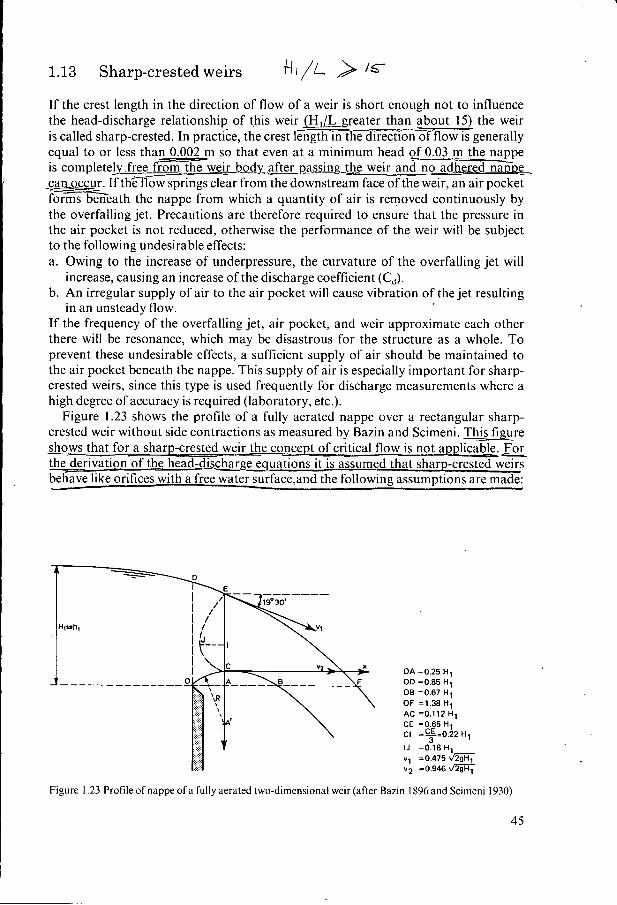
If the crest length in the direction of flow of a weir is short enough not to influence the head-discharge relationship of this weir (HJL greater than about 15) the weir is called sharp-crested. In practice, the crest length in the direction of-flow is generally equal to or less than 0.002 m so that even at a minimum head of3 m the nappe is complete!y free -we& body after Dassing-gh weir and no adheredñäEDg q a n z I f th3low springs clear from the downstream face of the weir, an air pocket forms beneath the nappe from which a quantity of air is removed continuously by the overfalling jet. Precautions are therefore required to ensure that the pressure in the air pocket is not reduced, otherwise the performance of the weir will be subject to the following undesirable effects: a. Owing to the increase of underpressure, the curvature of the overfalling jet will
b. An irregular supply of air to the air pocket will cause vibration of the jet resulting
If the frequency of the overfalling jet, air pocket, and weir approximate each other there will be resonance, which may be disastrous for the structure as a whole. To prevent these undesirable effects, a sufficient supply of air should be maintained to the air pocket beneath the nappe. This supply of air is especially important for sharp- crested weirs, since this type is used frequently for discharge measurements where a high degree of accuracy is required (laboratory, etc.).
Figure 1.23 shows the profile of a fully aerated nappe over a rectangular sharp- crested weir without side contractions as measured by Bazin and Scimeni. figure shows that for - a sharp-crested weir the concept of critical flow is not applicable. _For the derivation of the head-discharge equations it is assumed that sharp-crested weirs behave like orifices with a free water surface,and the following assumptions are made:
increase, causing an increase of the discharge coefficient (C,,).
in an unsteady flow.
L
OA = O 2 5 H1 OD =OB5 H1 O8 =OB7 H1 OF =1.38 H l AC =0.112 Hl CE = O 6 5 H1 CI ===0.22 H l
3 IJ =0.18 H1 v1 =0.475 v2 =0.946-
Figure 1.23 Profile of nappe of a fully aerated two-dimensional weir (after Bazin 1896 and Scimeni 1930)
45
i. the height of the water level above the weir crest is h = h, and there is no contrac- tion;
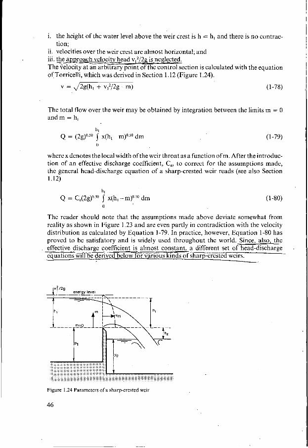
ii. velocities over the weir crest are almost horizontal; and iii. the apmoach velocity head ~ ~ ~ 1 2 . g is neglected. The;elociG=&ry point oTth-ection is calculated with the equation of Torricelli, which was derived in Section 1.12 (Figure 1.24).
v = J2g(h, + vI2/2g - m) (1-78)
The total flow over the weir may be obtained by integration between the limits m = O and m = h,
h, Q = (2g)0.50 f x(h, -m)o.50 dm
O
( 1 -79)
where x denotes the local width of the weir throat as a function of m. After the introduc- tion of an effective discharge coefficient, Ce, to correct for the assumptions made, the general head-discharge equation of a sharp-crested weir reads (see also Section 1.12)
hl Q = C,(2g)0.50 x(h, - m)0.50 dm
O
(1 -80)
The reader should note that the assumptions made above deviate somewhat from reality as shown in Figure 1.23 and are even partly in contradiction with the velocity distribution as calculated by Equation 1-79. In practice, however, Equation 1-80 has proved to be satisfatory and is widely used throughout the world. Since, also, the effective discharge coefficient is almost constant, a different set of head-discharge
ived below fo iVar iG kinds of sharp-crested weirs.
Figure I .24 Parameters of a sharp-crested weir
46
1.13.1
For a rectangular control section, (Figure 1.25) x = b, = constant, Equation 1-80 may be written as
Sharp-crested weir with rectangular control section
hl Q = Ce (2g)O so b,(h, - m)O 50 dm (1-81)
O
or n
(1 -82) L Q = Ce- (2g)O.” b, hl’.50 3
So, apart from a constant factor, Equation 1-82 has the same structure as the head- discharge relation for a broad-crested weir with rectangular control section (Equation 1-37).
. . . I I
Figure I .25 Dimensions of a rectangular control section
1.13.2
For a parabolic control section (Figure 1.26) x = 2@, and Equation 1-80 may be written as
Sharp-crested weir with parabolic control section
hl Q = Q,(2g)0.s0 1 2(2fm(h, - m)}o.so dm
O
After substituting m = h(l -cos a)/2, Equation 1-83 is transformed into
h 2 n Q = Ce(2g)0.s0 2(2f)0.50 [$] (1 - sin a da O
or
In the above a was introduced for.mathematical purposes only.
(1-83)
(1 -84)
47
I h,=h
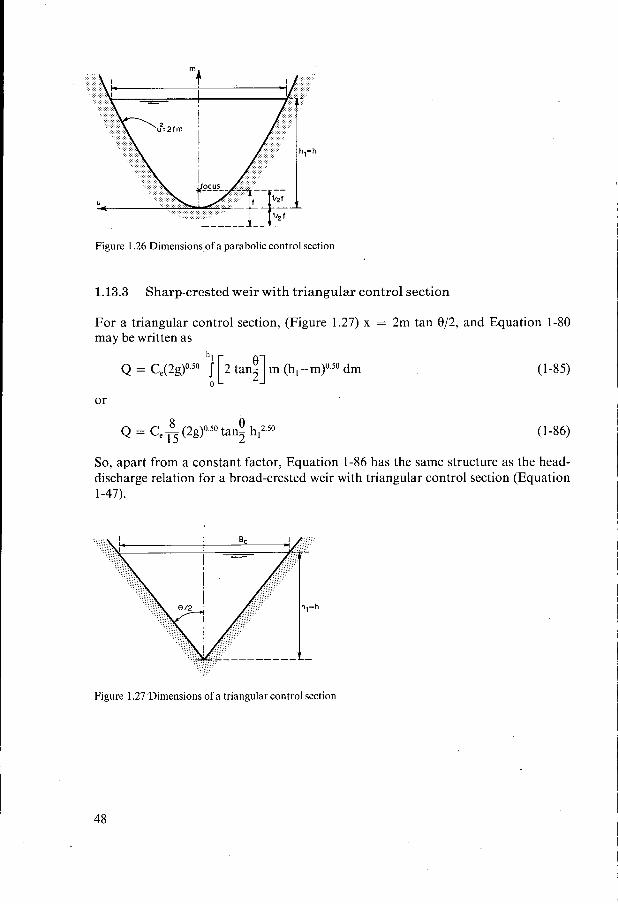
Figure 1.26 Dimensions of a parabolic control section
1.13.3 Sharp-crested weir with triangular control section
For a triangular control section, (Figure 1.27) x = 2m tan 0/2, and Equation 1-80 may be written as
h l Q = Ce(2g)0.50 J [2 tan;] m (h,-m)0.50 dm
O
(1-85)
or
(1 -86) 8 0 15 2 Q = Ce - (2g)0.50 tan- h,2.50
So, apart from a constant factor, Equation 1-86 has the same structure as the head- discharge relation for a broad-crested weir with triangular control section (Equation 1-47).
I J(
/ 4/
r-
Figure 1.27 'Dimensions of a triangular control section
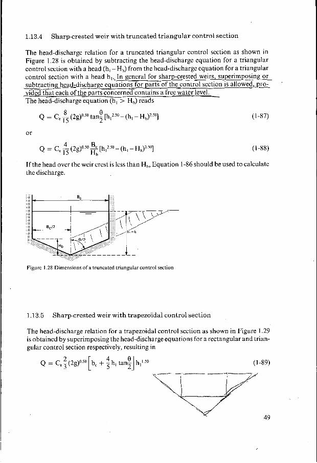
1.13.4 Sharp-crested weir with truncated triangular control section
The head-discharge relation for a truncated triangular control section as shown in Figure 1.28 is obtained by subtracting the head-discharge equation for a triangular control section with a head (h, -Hb) from the head-discharge equation for a triangular
(1 -88) 4 B Q = Ce - (2g)O [hI2 50 - (h, - Hb)' ' O ]
15 H b
If the head over the weir crest is less than H,, Equation 1-86 should be used to calculate the discharge.
Figure I .28 Dimensions of a truncated triangular control section
1.13.5 Sharp-crested weir with trapezoïdal control section
The head-discharge relation for a trapezoidal control section as shown in Figure 1.29 is obtained by superimposing the head-discharge equations for a rectangular and trian- gular control section respectively, resulting in
(1 -89)
Figure 1.29 Dimensions of a trapezoïdal control section
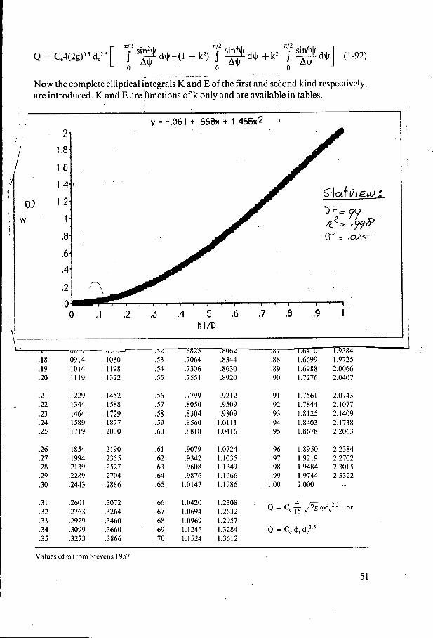
1.13.6 Sharp-crested weir with circular control section
For a circular control section as shown in Figure 1.30, the values for x, m, and dm can be written as x = 2 r sin c1 = d, sin 2p = 2 d, sin p cos p
m = r( 1 - cos a) = d, sin2 p dm = 2 d, sin p cos p dp
Substitution of this information into Equation 1-80 gives
bh Q = C,(2g)0.50 f (2d, sin p cos 0)’ (h, - d, sin2p)0.5 dp (1 -90)
O
h After introduction of k2 = 2 (being < 1) and some further modifications Equation 1-90 reads d,
Substitution of sin p = k sin $ and introduction of A$ = (1 ~ k2 ~in~$)O.~ leads to
Figure 1.30 Dimensions of a circular control section
50
' I2 sin2+ ' I2 sin4+
O A+ O O Q = Ce4(2g)o.sd,"[ J -d+-(1 + k2) j wd+ +k2 j
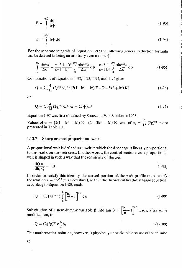
-. . - - - _ _ _ - Now the complete elliptical integrals K and E of the first and second kind respectively, are introduced. K and E are functions of k only and are available in tables.
Equation 1-97 was first obtained by Staus and Von Sanden in 1926.
(1 -95)
( I -96)
(1-97)
4 15 Values of o = {2(1 - k2 + k4) E - (2 - 3k2 + k4) K} and of +i = - (2g)0.5 o are
presented in Table 1.3.
1.13.7 Sharp-crested prbportional weir
A proportional weir is defined as a weir in which the discharge is linearly proportional to the head over the weir crest. In other words, the control section over a proportional weir is shaped in such a way that the sensitivity of the weir
;:; = 1.0 (1 -98)
In order to satisfy this identity the curved portion of. the weir profile must satisfy the relation x = ~ n ' ) . ~ (cis a constant), so that the theoretical head-discharge equation, according to Equation 1-80, reads
h
Q = Ce (2g)0-5 c J [;- I r 5 dn O
(1 -99)
0.5 Substitution of a new dummy variable p into tan p. = [:- I ] leads, after some modification, to
7c Q = C,(2g)0.5 c - h, (1-100) 2
This mathematical solution, however, is physically unrealizable because of the infinite
52
wings of the weir throat at n = O. To overcome this practical limitation, Sutro (1908) proposed that the weir profile should consist of a rectangular portion at the base of the throat and a curved portion above it, which must have a different profile law to maintain proportionality.
The discharge through the rectangular section under a head h, above the weir crest equals, according to Equation 1-82
(1-101) L Q, = Ce 3 (2g)O.’ b, [hl’.5 - ho’.’]
where’ b, equals the width of the rectangular portion, ho = (h,-a) equals the head over the boundary line CD, and ‘a’ equals the height of the rectangular portion of the control section as shown in Figure 1.3 I . The discharge through the curved portion of the weir equals according to Equation 1-80
h0
Q, = Ce(2g)0.’ 1 (ho - n’)0.5 xdn’ O
(1-102)
Thus the total discharge through the weir equals ho
The discharge through the weir must be proportional to the head above an arbitrarily chosen reference level situated in the rectangular portion of the weir. The reference level AB is selected at a distance of one-third of the rectangular portion above the weir crest to facilitate further calculations. So the total discharge through the weir also reads
Q = K(h, -a/3)’ (1-104)
where K is a weir constant. Since proportionality is valid for heads equal to or above the boundary line CD, it must hold also if ho = O. Substitution of ho = O and h, = a into Equations 1-103 and 1-104gives
Figure I .31 Dimensions of a proportional Sutro weir notch
53
A
2 3 Q = Ce - (2g)0.5 b, a'.5 and
2 Q = - K a 3
Consequently the weir constant equals
K = Ceb,(2ga)'.' . ( 1 - 1 05)
Substitution of the latter equation into Equation 1-104 gives
Q = C, (2ga)0.5 b,(h, - a/3) (1-106)
as a head-discharge equation. The relationship between x and n' for the curved position of the weir can be obtained from the condition that Equations 1-103 and 1-106 should be equal to each other, thus
From this equation h, and ho can be eliminated and the following relationship between x and n can be obtained (Pratt 1914).
X/b, = 1 ( 1 - 1 07)
1.14 The aeration demand of weirs
Under those circumstances where the overfalling jet is not in contact with the body of the weir, an air pocket exists under the nappe from which a quantity of air is removed continuously by the overfalling jet. If the air pocket is insufficiently aerated, an under- pressure is created. This underpressure increases the curvature of the nappe. One of the results of this feature is an increase of the discharge coefficient (CJ. For a given head (h,) the discharge is increased, and if the discharge is fixed, the measured head over the weir is reduced. Obviously, this phenomenon is not a desirable one as far as discharge measuring weirs are concerned.
Based on data provided by Howe (1955) the writers have been able to find a relation- ship that gives the maximum demand of air (qJ required for full aeration in m3/s per metre breadth of weir crest as
(1-108)
where q, equals the unit discharge over the weir, h, is the head over the weir, and yp equals the water depth in the pool beneath the nappe as shown in Figure 1.32. The poolwater depth yp is either a function of the tailwater level or of the unit discharge q, and the drop height AZ. If a free hydraulic jump is formed downstream of the weir, yp may be calculated with Equation 1- 109, which reads
54
en-y level y---
required air SUPPIY:q,ir
Figure I .32 Definition sketch aeration demand
0.22
YP = AZ(&) (1-109)
The dimensionless ratio q2/gAz3 is generally known as the drop number. If the jump downstream of the weir is submerged, the poolwater depth may be expected to be about equal to the tailwater depth; yp N y2.
I As an example we consider a fully suppressed weir with a breadth b, = 6.50 m and water discharging over it under a head hl = 0.60 m, giving a unit discharge of 0.86
air demand for full aeration under these conditions as
~
I m3/s per metre, while the pool depth yp = 0.90 m. Equation 1-108 gives the maximum
- 0.047 m3/s per metre (0.90/0.60)1.5 - qair = 0.1
or 6.5 x 0.047 = 0.305 m3/s for the'full breadth of the weir. The diameter of the air vent(s) to carry this air flow can be determined by use of the ordinary hydrodynami- cal equations, provided the underpressure beneath the nappe is low so that the mass density of air (pair) can be considered a constant. In calculating the air discharge, how- ever, the effective head over the vent must be stated in metres air-column rather than in metres water-column. For air at 20°C, the ratio pair/pwater equals approximately 11830.
To facilitate the flow of air through the vent(s) a differential pressure is required over the vent, resulting in an underpressure beneath the nappe. In this example we suppose that the maximum permissible underpressure equals 0.04 m water column.
Suppose that the most convenient way of aeration is by means of one steel pipe 2.50 m long with one right-angle elbow and a sharp cornered entrance; the head-loss over the vent due to the maximum air discharge then equals