Read through the fitting instructions before installation of the accessory. Install the accessory following the fitting instructions. Failure to do so may cause damage to the vehicle or the accessory.
Ensure all recyclables, discarded vehicle accessory components and packaging are recycled following local recycling regulations.
It is always recommended that this accessory is fitted by a qualified automotive Technician.
Safely store and protect any removed vehicle components.
Ensure all bare metal surfaces are protected using automotive bare metal primer and touch-up paint, or suitable automotive rust inhibitor.
Remove all metals swarf and dust from all vehicle surfaces if surfaces is used for accessory installation.
•
•
Check that all work practices comply with safety standards.
Please wear appropriate clothing and use safety equipment.
Ratchet Socket Set Guide wirePhillips Head Screw Driver Trim Removal Tools PVC Tape
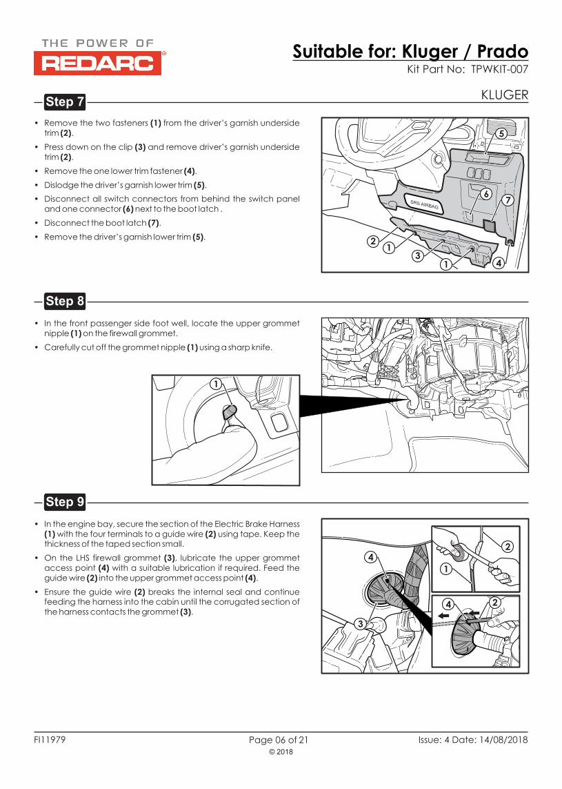
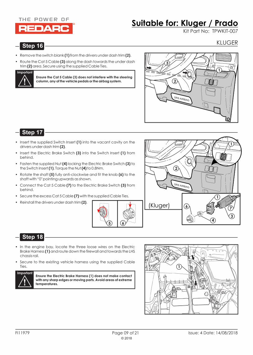
• Remove the two fasteners (1) from the driver’s garnish underside trim (2).
• Press down on the clip (3) and remove driver’s garnish underside trim (2).
• Remove the one lower trim fastener (4).
• Dislodge the driver’s garnish lower trim (5).
• Disconnect all switch connectors from behind the switch panel and one connector (6) next to the boot latch .
• Disconnect the boot latch (7).
• Remove the driver’s garnish lower trim (5).
1
1
2
4
5
7SRS AIRBAG
3
6
• In the front passenger side foot well, locate the upper grommet nipple (1) on the firewall grommet.
• Carefully cut off the grommet nipple (1) using a sharp knife.
1
• ecure the section of the Electric Brake Harness (1) with the four terminals to a guide wire (2) using tape. Keep the thickness of the taped section small.
• On the LHS firewall grommet (3), lubricate the upper grommet access point (4) with a suitable lubrication if required. Feed the guide wire (2) into the upper grommet access point (4).
• Ensure the guide wire (2) breaks the internal seal and continue feeding the harness into the cabin until the corrugated section of the harness contacts the grommet (3).
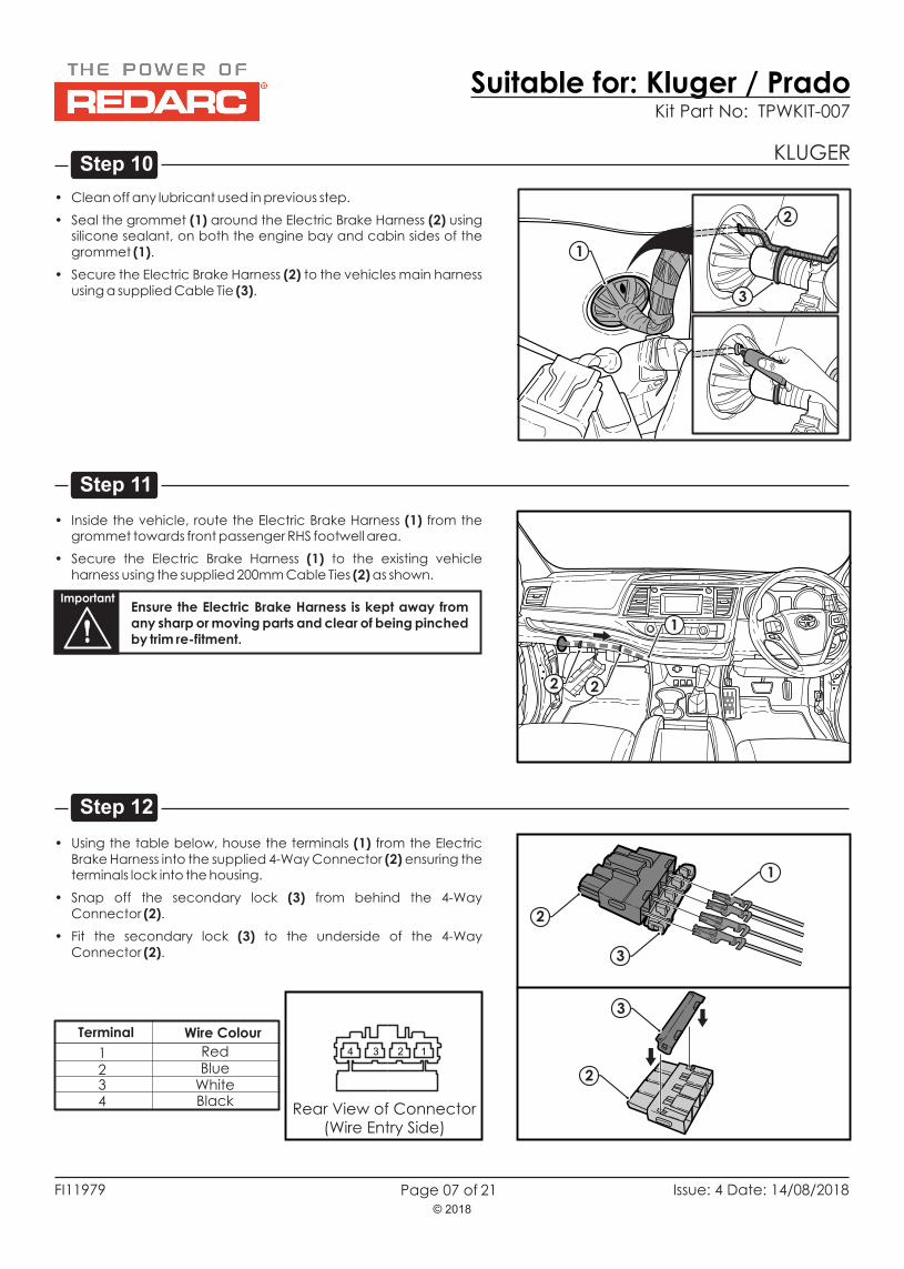
• Seal the grommet (1) around the Electric Brake Harness (2) using silicone sealant, on the engine bay and cabin sides of the grommet (1).
• Secure the Electric Brake Harness (2) to the vehicles main harness using a supplied Cable Tie (3).
both
• Inside the vehicle, route the Electric Brake Harness (1) from the grommet towards front passenger RHS footwell area.
• Secure the Electric Brake Harness (1) to the existing vehicle harness using the supplied 200mm Cable Ties (2) as shown.
ImportantEnsure the Electric Brake Harness is kept away from any sharp or moving parts and clear of being pinched by trim re-fitment.
3
2
1
1
2 2
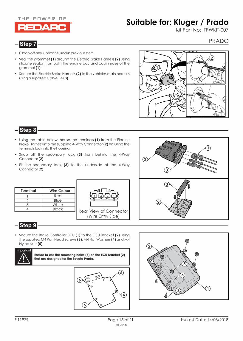
• Using the table below, house the terminals (1) from the Electric Brake Harness into the supplied 4-Way Connector (2) ensuring the terminals lock into the housing.
• Snap off the secondary lock (3) from behind the 4-Way Connector (2).
• Fit the secondary lock (3) to the underside of the 4-Way Connector (2).
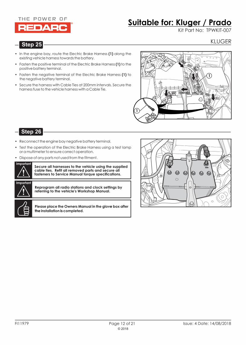
• In the engine bay, route the Electric Brake Harness (1) along the existing vehicle harness towards the battery.
• Fasten the positive terminal of the Electric Brake Harness (1) to the positive battery terminal.
• Fasten the negative terminal of the Electric Brake Harness (1) to the negative battery terminal.
• Secure the harness with Cable Ties at 200mm intervals. Secure the harness fuse to the vehicle harness with a Cable Tie.
• Reconnect the engine bay negative battery terminal.
• Test the operation of the Electric Brake Harness using a test lamp or a multimeter to ensure correct operation.
• Dispose of any parts not used from the fitment.
Please place the Owners Manual in the glov box after installation completed.
e the is
ImportantSecure all harnesses to the vehicle using the supplied cable ties. Refit all removed parts and secure all fasteners to Service Manual torque specifications.
Important
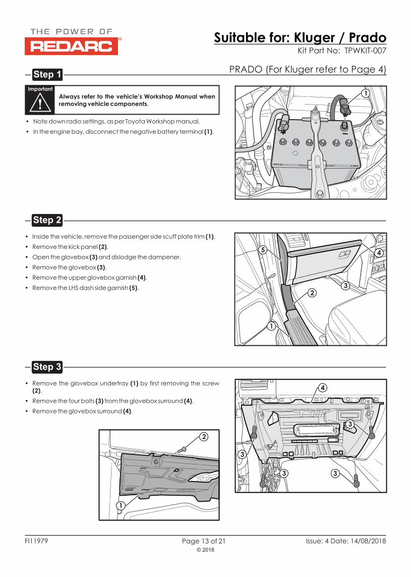
Reprogram all radio stations and clock settings by referring to the vehicle's Workshop Manual.
• Remove the vehicle switch blank (3) by pushing from behind.
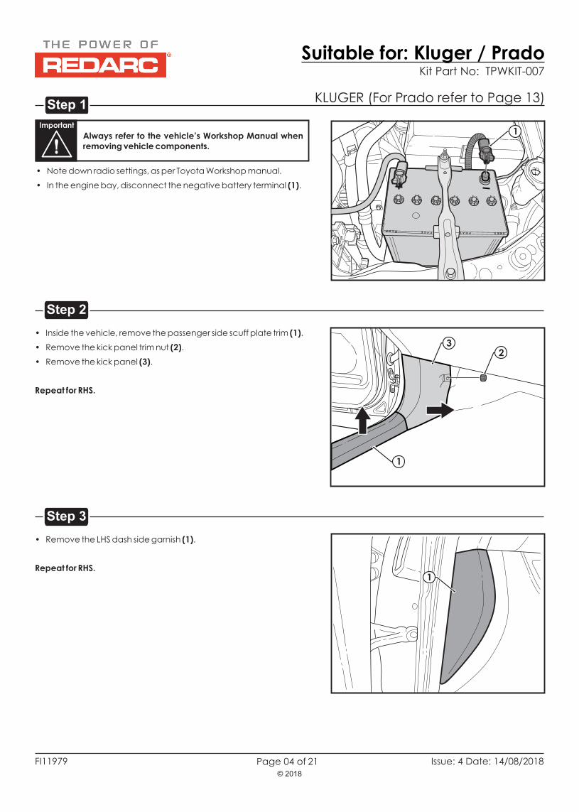
Remove the RHS dash side garnish (1).
1
2
3
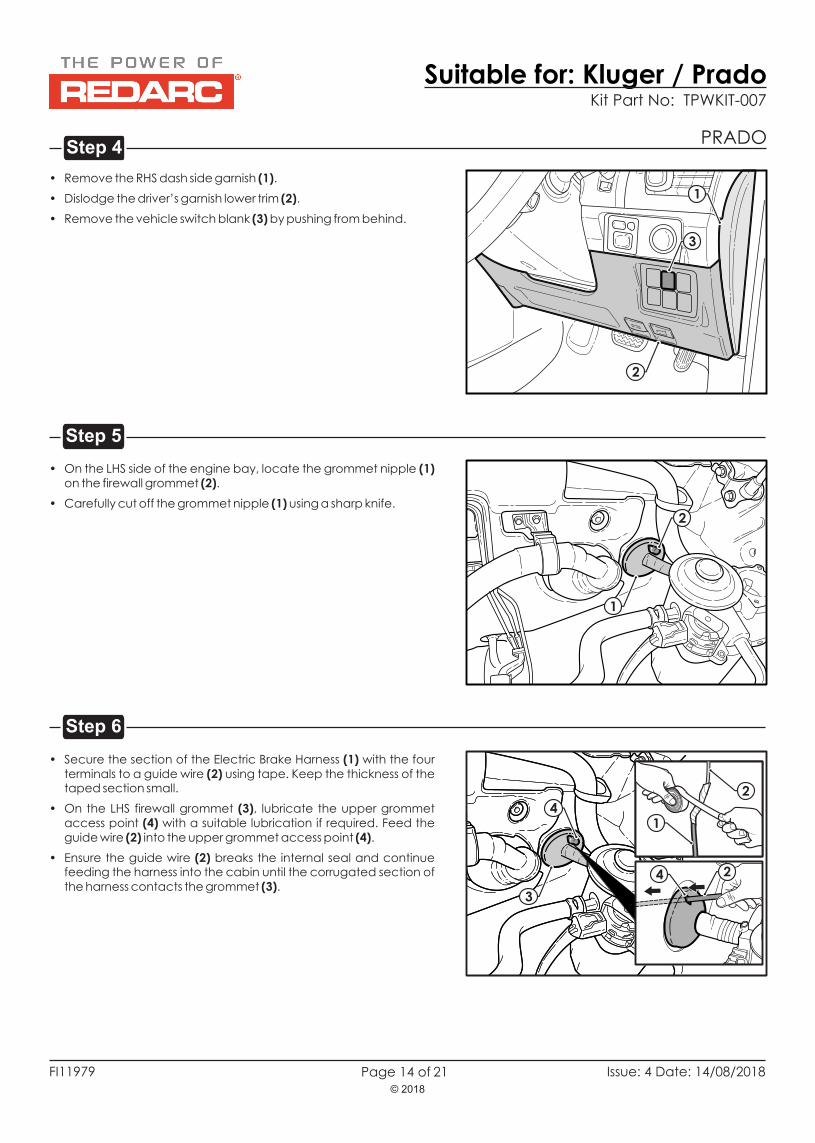
• On the LHS side of the engine bay, locate the grommet nipple (1) on the firewall grommet (2).
• Carefully cut off the grommet nipple (1) using a sharp knife.
2
1
• ecure the section of the Electric Brake Harness (1) with the four terminals to a guide wire (2) using tape. Keep the thickness of the taped section small.
• On the LHS firewall grommet (3), lubricate the upper grommet access point (4) with a suitable lubrication if required. Feed the guide wire (2) into the upper grommet access point (4).
• Ensure the guide wire (2) breaks the internal seal and continue feeding the harness into the cabin until the corrugated section of the harness contacts the grommet (3).
• Using the table below, house the terminals (1) from the Electric Brake Harness into the supplied 4-Way Connector (2) ensuring the terminals lock into the housing.
• Snap off the secondary lock (3) from behind the 4-Way Connector (2).
• Fit the secondary lock (3) to the underside of the 4-Way Connector (2).
Step 7
Step 9
Step 8
• Clean off any lubricant used in previous step.
• Seal the grommet (1) around the Electric Brake Harness (2) using silicone sealant, on the engine bay and cabin sides of the grommet (1).
• Secure the Electric Brake Harness (2) to the vehicles main harness using a supplied Cable Tie (3).
both 1
Wire ColourTerminal
1234
RedBlue
WhiteBlack
Rear View of Connector(Wire Entry Side)
4 3 2 1
2
3
3
2
Page 15 of
PRADO
• Secure the Brake Controller ECU (1) to the ECU Bracket (2) using the supplied M4 Pan Head Screws (3), M4 Flat Washers (4) and M4 Nyloc Nuts (5).
Important
Ensure to use the mounting holes (6) on the ECU Bracket (2) that are designed for the Toyota Prado.
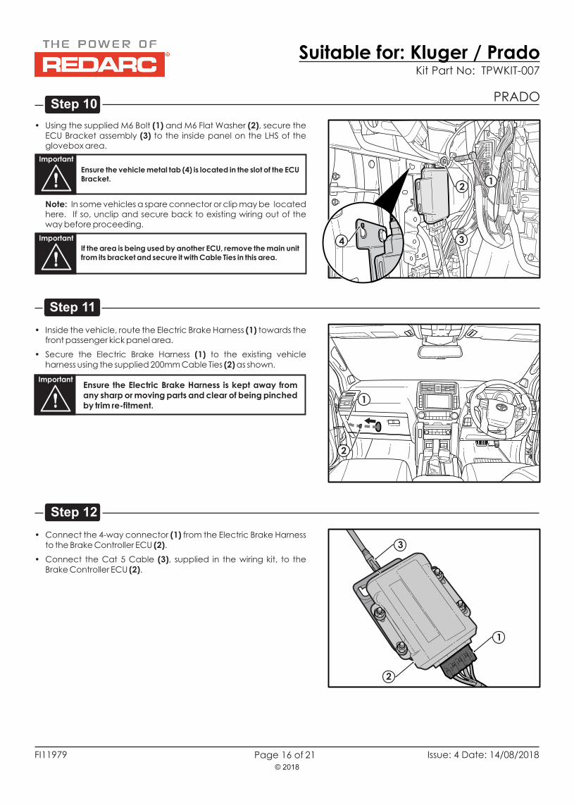
• Using the supplied M6 Bolt (1) and M6 Flat Washer (2), secure the ECU Bracket assembly (3) to the inside panel on the LHS of the glovebox area.
Important
Ensure the vehicle metal tab (4) is located in the slot of the ECU Bracket.
21
3
• Connect the 4-way connector (1) from the Electric Brake Harness to the Brake Controller ECU (2).
• Connect the Cat 5 Cable (3), supplied in the wiring kit, to the Brake Controller ECU (2).
1
2
3
Page 16 of
PRADO
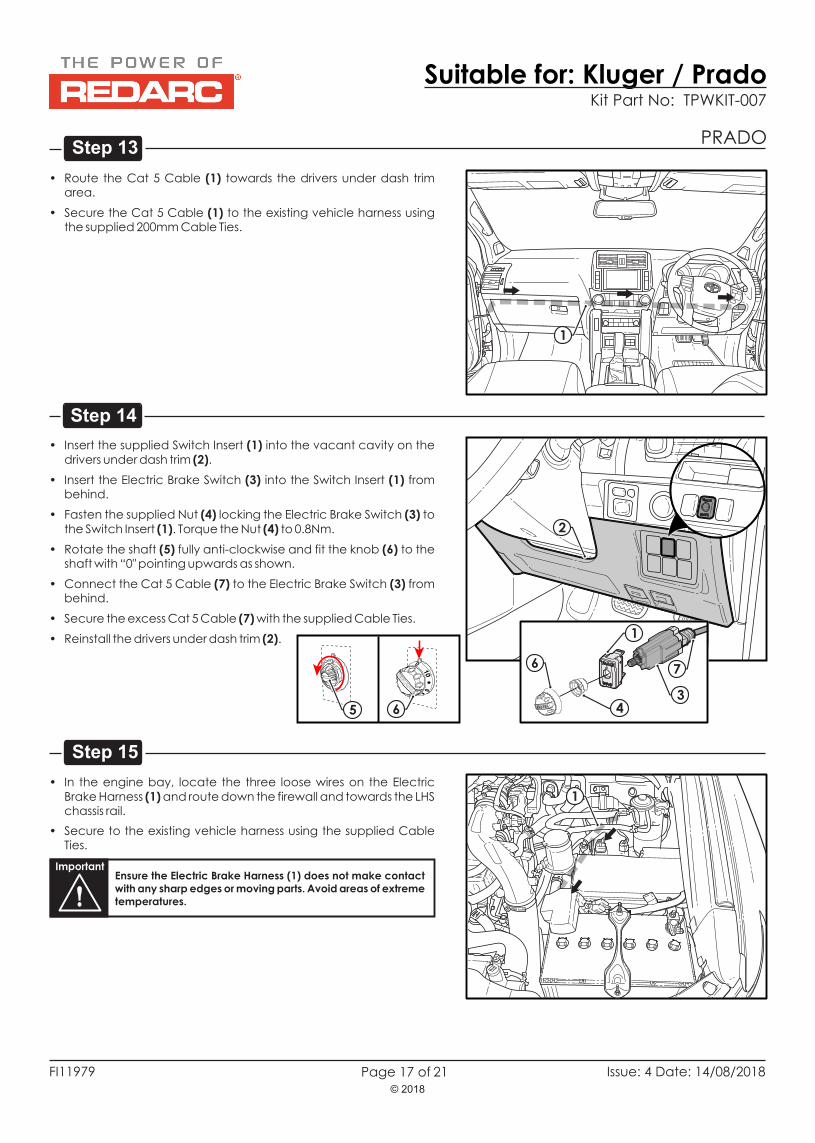
• Inside the vehicle, route the Electric Brake Harness (1) towards the front passenger kick panel area.
• Secure the Electric Brake Harness (1) to the existing vehicle harness using the supplied 200mm Cable Ties (2) as shown.
ImportantEnsure the Electric Brake Harness is kept away from any sharp or moving parts and clear of being pinched by trim re-fitment.
1
2
Note: In some vehicles a spare connector or clip may be located here. If so, unclip and secure back to existing wiring out of the way before proceeding.
Important
If the area is being used by another ECU, remove the main unit from its bracket and secure it with Cable Ties in this area.
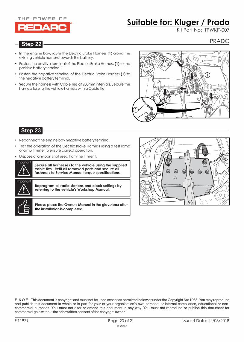
• In the engine bay, route the Electric Brake Harness (1) along the existing vehicle harness towards the battery.
• Fasten the positive terminal of the Electric Brake Harness (1) to the positive battery terminal.
• Fasten the negative terminal of the Electric Brake Harness (1) to the negative battery terminal.
• Secure the harness with Cable Ties at 200mm intervals. Secure the harness fuse to the vehicle harness with a Cable Tie.
• Reconnect the engine bay negative battery terminal.
• Test the operation of the Electric Brake Harness using a test lamp or a multimeter to ensure correct operation.
• Dispose of any parts not used from the fitment.
Please place the Owners Manual in the glov box after installation completed.
e the is
ImportantSecure all harnesses to the vehicle using the supplied cable ties. Refit all removed parts and secure all fasteners to Service Manual torque specifications.
Important
Reprogram all radio stations and clock settings by referring to the vehicle's Workshop Manual.
1
E. & O.E. This document is copyright and must not be used except as permitted below or under the Copyright Act 1968. You may reproduce and publish this document in whole or in part for your or your organisation's own personal or internal compliance, educational or non-commercial purposes. You must not alter or amend this document in any way. You must not reproduce or publish this document for commercial gain without the prior written consent of the copyright owner.


![Yuval Kluger arXiv:1801.01587v6 [stat.ML] 4 Apr 2018](https://static.documents.pub/doc/80x56/623b64c53bbd3611345d2f27/yuval-kluger-arxiv180101587v6-statml-4-apr-2018.jpg)


