48
FibeAir ® 3200T SDH Microwave Trunk Network Solution Product Description Version 5.5 December 2007
| Date post: | 21-Mar-2018 |
| Category: |
Documents |
| Upload: | hoangkhanh |
| View: | 228 times |
| Download: | 3 times |
FibeAir® 3200T
SDH Microwave Trunk Network Solution
Product Description
Version 5.5 December 2007

Notice This document contains information that is proprietary to Ceragon Networks Ltd.
No part of this publication may be reproduced, modified, or distributed without prior written authorization of Ceragon Networks Ltd.
This document is provided as is, without warranty of any kind.
Registered TradeMarks Ceragon Networks® , FibeAir® and CeraView® are registered trademarks of Ceragon Networks Ltd.
Other names mentioned in this publication are owned by their respective holders.
TradeMarks CeraMapTM, ConfigAirTM, PolyViewTM, EncryptAirTM, CeraMonTM, EtherAirTM, and MicroWave FiberTM, are trademarks of Ceragon Networks Ltd.
Other names mentioned in this publication are owned by their respective holders.
Statement of Conditions The information contained in this document is subject to change without notice.
Ceragon Networks Ltd. shall not be liable for errors contained herein or for incidental or consequential damage in connection with the furnishing, performance, or use of this document or equipment supplied with it.
Information to User Any changes or modifications of equipment not expressly approved by the manufacturer could void the user’s authority to operate the equipment and the warranty for such equipment.
Copyright © 2007 by Ceragon Networks Ltd. All rights reserved.
Corporate Headquarters: Ceragon Networks Ltd. 24 Raoul Wallenberg St. Tel Aviv 69719, Israel Tel: 972-3-645-5733 Fax: 972-3-645-5499 Email: [email protected] www.ceragon.com
European Headquarters: Ceragon Networks (UK) Ltd. 4 Oak Tree Park, Burnt Meadow Road North Moons Moat, Redditch, Worcestershire B98 9NZ, UK Tel: 44-(0)-1527-591900 Fax: 44-(0)-1527-591903 Email: [email protected]
North American Headquarters: Ceragon Networks Inc. 10 Forest Avenue, Paramus, NJ 07652, USA Tel: 1-201-845-6955 Toll Free: 1-877-FIBEAIR Fax: 1-201-845-5665 Email: [email protected]
APAC Headquarters: Ceragon Networks APAC (S'pore) Pte Ltd 100 Beach Road #27-01/03 Shaw Towers Singapore 189702 Tel.: 65 65724170 Fax: 65 65724199

Contents
General ...........................................................................................................................1
System Overview...........................................................................................................1
Main Features ................................................................................................................3
Applications ...................................................................................................................4
System Configurations .................................................................................................6
Frequency Bands ..........................................................................................................7
FibeAir 3200T Diagrams and Illustrations...................................................................8
FibeAir 3200T Components ........................................................................................15
Power Supply...............................................................................................................21
Power Consumption....................................................................................................21
Waveguide Flange .......................................................................................................22
Mean Time Between Failures (MTBF) ........................................................................23
Branching Loss ...........................................................................................................23
Auxiliary Channels ......................................................................................................23
Radio Protection Switching........................................................................................25
Link Topologies ...........................................................................................................28
Management.................................................................................................................29
Environmental Conditions Standard Compliance....................................................30
Safety Conditions Standard Compliance ..................................................................30
FibeAir 3200T Specifications (STM-1) .......................................................................31
Appendix: Frequency Channels.................................................................................33

FibeAir® 3200T Product Description 1
General
Constant network expansion in this day of fast-paced communication has brought with it the need for increased capacity, long distance links, simplicity of installation, and more robust backbone and long-haul infrastructure.
Ceragon’s FibeAir 3200T is a low frequency, high capacity, N+1 trunk radio system that was designed to respond to those needs.
System Overview
Ceragon’s FibeAir 3200T supports multiple capacities, frequencies, modulation schemes, and configurations for various network requirements.
FibeAir 3200T operates in the frequency range of 6-11 GHz, and its capacities support up to 10 x 155 Mbps. In addition, a redundant channel provides backup in the event of equipment failure or degradation on specific frequency channels.
FibeAir 3200T was designed to provide maximum protection and availability for backbone networks. Featuring N+1 switching protection, embedded space diversity, and ultra high power, operators can greatly improve hop length, system performance and availability.
The FibeAir 3200T long haul trunk solution includes value-added features, such as full TDM and IP capabilities and unique flexibility options. The same hardware is used for both split-mount and all-indoor installations, providing the customer with maximum flexibility to meet their wide range of requirements.
FibeAir 3200T has an ultra high power transmitter, which reaches longer distances and helps reduce system cost due to the usage of smaller antennas. Thus, high quality communication is achieved, with less cost.
For installation flexibility, the FibeAir 3200T Trunk Radio system can be assembled in one of two configurations:
All-Indoor installation, with the entire system installed in a rack
Split-Mount installation, with the RFUs installed near the antenna
FibeAir 3200T specifications are in accordance with the relevant ITU, ETSI, and IEC international standards.

FibeAir® 3200T Product Description 2
3200T System Diagram
The following illustration shows the 3200T system structure and components.

FibeAir® 3200T Product Description 3
Main Features
Operates in the frequency range of 6-11 GHz
N+1 carrier protection
Two possible installation types:
- 3200T All-Indoor: 1+0 to 9+1/10+0
- 3200T Split-Mount: 1+0 to 5+1/6+0
Protected Configurations: 1+1 Hot Standby, 1+1 to 9+1 Frequency Diversity, Co-channel operation with XPIC (CCDP)
Note: all configurations are available with Space Diversity, using an innovative digital multi-mode IF combiner.
High transmit power:
3200T All-Indoor: 32/33 dBm
3200T Split-Mount: 29dBm
Capacity: up to 10 x 155 Mbps
Modulation: 64/128 QAM
Channel bandwidth: 28/29.65/30/40 MHz
Two receivers and one transmitter in a single transceiver unit, for built-in Diversity capability
Innovative digital multi-mode IF combiner
Both configurations, All-Indoor and Split-Mount, use the same hardware
Simple and flexible installation
Light weight system
Different capacities and interfaces, using different indoors: 3200T, 1500P, IP-MAX, 640P
Compliant with ETSI, FCC, ITU-T, and ITU-R standards for worldwide operation
Advanced CeraView® - Java-based SNMP element manager, and PolyView™ - open interface network management system.
3200T baseband indoor can operate with 1500SP ODUs (6-8 GHz) and 1500P (11-38 GHz ) ODUs.
FibeAir® 3200T Product Description 4
Applications
FibeAir 3200T can be used for a variety of applications, as a flexible and cost-effective trunk network solution.
In addition to trunk N+1 x 155 Mbps configurations, for maximum link optimization, all Ceragon indoor unit types can be connected to the RFU subrack for all-indoor configurations.
The following indoor units can be configured for 1+0, 1+1, 2+0, and east-west communication, in an all-indoor installation:
FibeAir 1500P - DS3/STM-1/OC-3 interfaces
FibeAir IP-MAX - FE/GbE + 8xE1/T1
FibeAir 640P - up to 64xE1/T1 + FE
In addition, the 3200T baseband indoor can operate with 1500SP ODUs (6-8 GHz) and 1500P ODUs (11-38 GHz).
The following are the types of applications for which FibeAir 3200T is optimally suited.
Long Distance Connectivity
For both fixed line and mobile operators, FibeAir 3200T trunk networks provide long distance connectivity.
Use of lower frequencies, which require high transmit power and Space Diversity, together with STM-1/OC-3 capacity and N+1 carriers, enables FibeAir 3200T to facilitate backbone long-haul network building.
Mobile and Fixed Infrastructure
Quickly deployed and optimized for long-haul trunk applications, FibeAir 3200T is ideal for growing networks that demand very high capacities with multiple STM-1/OC-3 carriers. With scaleable capacity of up to N+1 carriers, operators can easily expand their networks to meet the huge increase in users, cell sites, and bandwidth-hungry applications.
The 3200T system offers smooth migration from PDH to SONET/SDH networks and next generation IP, with capacities of n x DS3, n x E1/DS1, FE, 2 x FE, and GbE. Applications include voice, Internet, PABX, DSL, video, VoIP, and others.

FibeAir® 3200T Product Description 5
Broadcast Networks
With very high capacity and ultra-long distance radio hop capability, FibeAir 3200T is an economic choice for cross-country digital broadcast connectivity. The scalability and reliability of the FibeAir solution are ideal for high-quality transport of contribution and distribution services. Applications include Digital Video Broadcast, TV, radio, and telemedicine.
Utilities & Private Networks
FibeAir 3200T provides high-capacity connectivity for enterprise LAN and PBX systems. Its hardware optimization significantly reduces equipment requirements for low frequency long haul radio hops, resulting in lower operation and maintenance costs. FibeAir 3200T is ideal for utility operators, corporate enterprises, education campuses, hospitals, banks, and others.
Applications include TDM connectivity, IP LAN connectivity, (FE/GbE), VoIP, client-server application, remote storage, video conferencing, infrastructure redundancy, and more.

FibeAir® 3200T Product Description 6
System Configurations
FibeAir 3200T is an N+1 Trunk Radio system that includes transceivers and Baseband Indoor units. The radio is a regenerator, RST (Regenerator Section Termination), in accordance with ITU-T Rec. G.783.
The following configurations are supported:
Unprotected
Data is transmitted through N channels, without redundancy (protection).
- All-Indoor: 1+0 to 10+0
- Split-Mount: 1+0 to 6+0
Hot Standby (both configurations)
Two RFUs (RF Units) use the same RF channel, whereby one channel transmits and the other acts as a backup (standby).
N+1 Frequency Diversity
Data is transmitted through N channels, and an additional RF channel protects the data by transmitting in a different frequency.
Frequency Diversity configurations can be expanded to up to 9+1. The system is mechanically prepared for traffic channel expansion.
In addition, in N+1 Frequency Diversity systems, a low priority traffic channel can be transmitted on the protection channel (Occasional Traffic), without the need for additional equipment.
- All-Indoor: 1+1 to 9+1
- Split-Mount: 1+1 to 5+1
Note: The N+1 Frequency Diversity (N>1) is not applicable for FibeAir 1500P, IP MAX, or 640P indoors.
Note: Space Diversity can be used in each of the configurations (HSB, N+0, and N+1).

FibeAir® 3200T Product Description 7
Frequency Bands
The frequency bands supported by FibeAir 3200T are listed in the following table.

FibeAir® 3200T Product Description 8
FibeAir 3200T Diagrams and Illustrations
The FibeAir 3200T system is composed of three main components:
Branching System
Baseband Indoor
RFUs
System Block Diagrams
The following are block diagrams of the FibeAir 3200T system and its main components.
3200T 4+1 Single Pole System Block Diagram
FibeAir® 3200T Product Description 9
RST
RST
RST
RST
RST
RST
RST
MODEM
MODEM
MODEM
MODEM
MODEM
MODEM
MODEM
MODEM
MODEM
RST
RST
RFU
s
N+1
Sw
itchi
ng
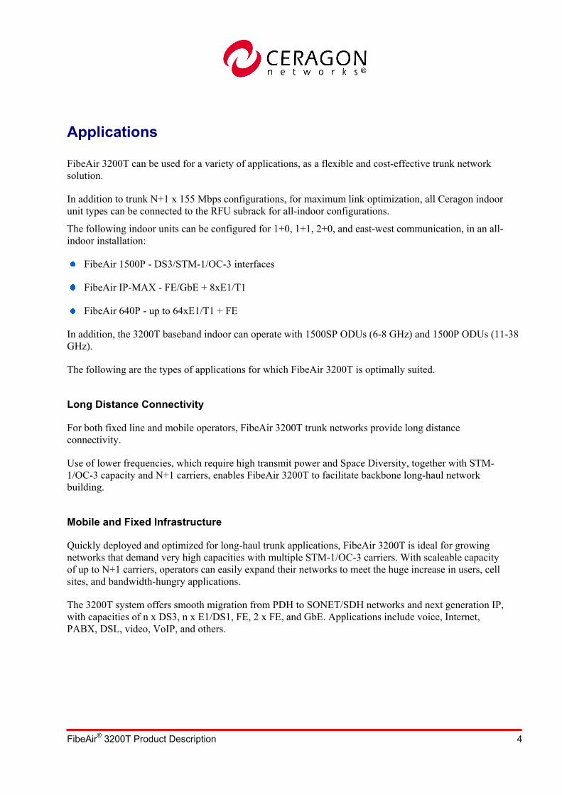
3200T 9+1 Dual Pole System Block Diagram

FibeAir® 3200T Product Description 10
Ω50
Ω50
ICC 1
WG
Subrack 1
Subrack 2Ω50
Ω50
ICC 2
WG
Tx1Tx2 Tx3 Tx Tx4
Tx6 Tx7 Tx8
Tx
R x1R x2R x3Rx4R x
R x6R x8 R x7
Rx5
T x9T x10
T x5
R x9R x10
3200T Branching System Electrical Diagram

FibeAir® 3200T Product Description 11
3200T 3+1 Baseband Indoor Block Diagram
FibeAir® 3200T Product Description 12
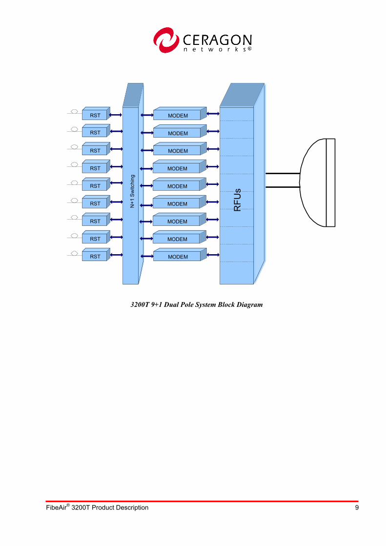
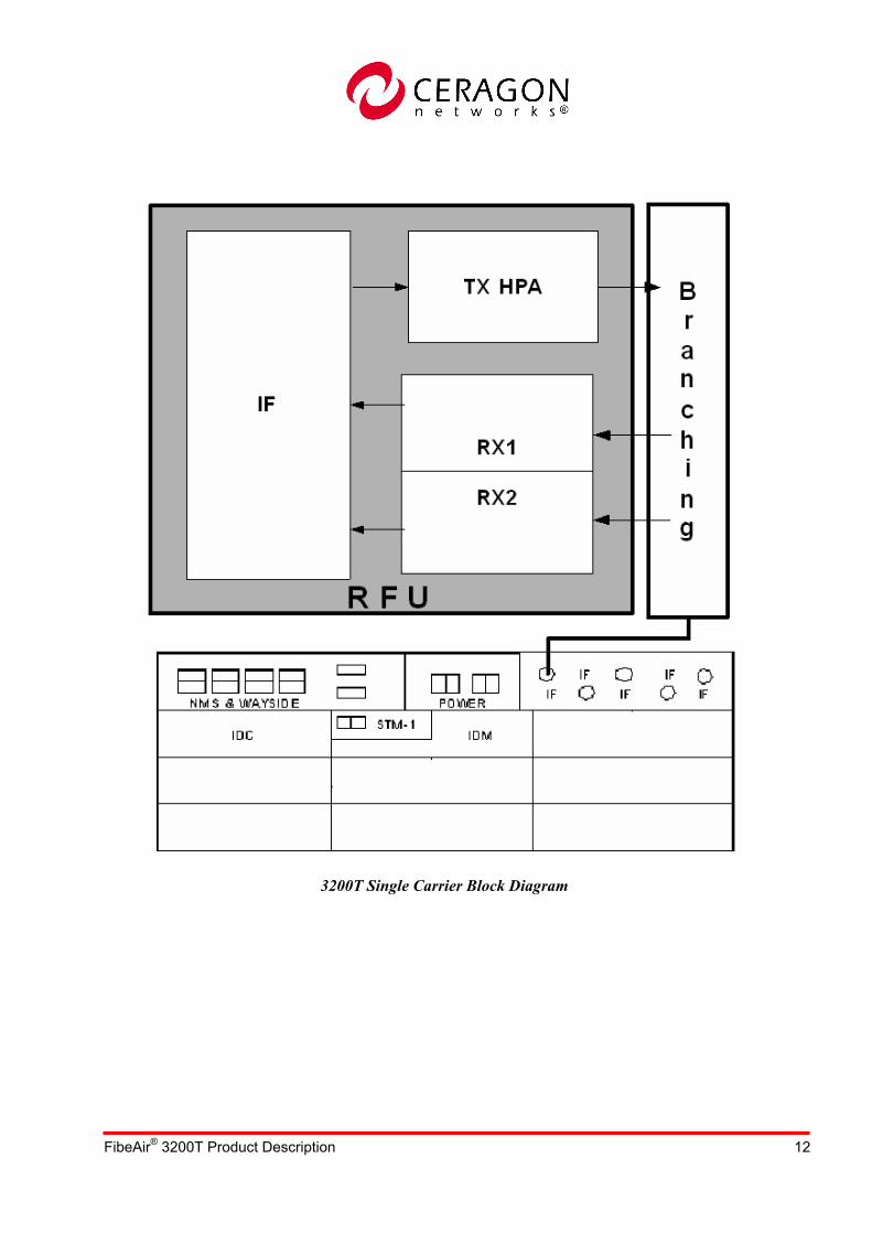
3200T Single Carrier Block Diagram
FibeAir® 3200T Product Description 13
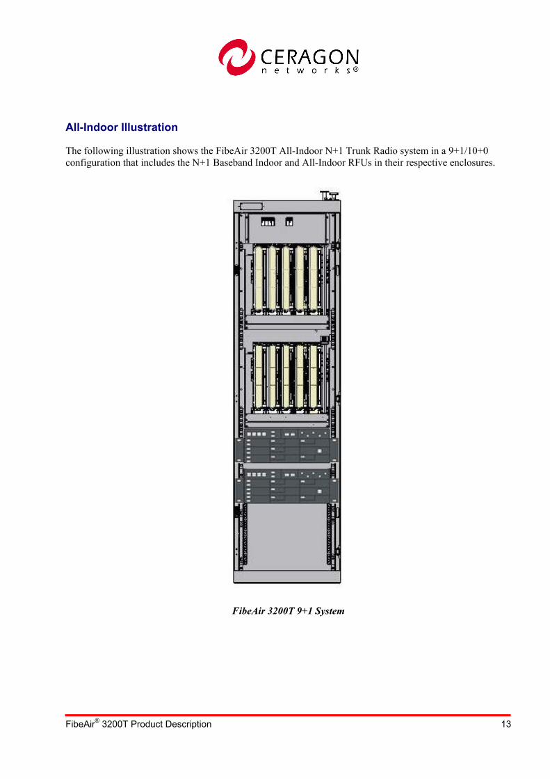
All-Indoor Illustration
The following illustration shows the FibeAir 3200T All-Indoor N+1 Trunk Radio system in a 9+1/10+0 configuration that includes the N+1 Baseband Indoor and All-Indoor RFUs in their respective enclosures.
FibeAir 3200T 9+1 System

FibeAir® 3200T Product Description 14
Rack and Subrack Dimensions

FibeAir® 3200T Product Description 15
FibeAir 3200T Components
RFU Subrack Components
FibeAir 3200T RFU Subrack
Subrack
The subrack hosts all the RFU components and connections, as shown in the illustration below.
The subrack includes:
ICBs - up to five ICBs per subrack
ICCs - up to two ICCs per subrack
ICCDs - if space diversity is used, the ICC will include two output ports, main and diversity
RFUs - up to five RFUs per subrack (each RFU connects to an ICB)
Filters - up to three filters per subrack (Tx and 2 x Rx), connected to each ICB
Patch Panel - part of the subrack; IF and XPIC cables are connected to the panel
Fan Tray - contains eight controlled and monitored fans, which cool the RFU heat dissipations
RFU
IBN
ICB

FibeAir® 3200T Product Description 16
RFU - RF Unit
The RFU handles the main radio processing. It includes the following radio components: signal receiving, signal transmission, IF processing, and power supply.
IF processing is a module that combines two signals, main and diversity, and uses the combined signal to overcome multipath phenomenon (for Space Diversity configurations).
The RFU has different versions, depending on the frequency band.
IBN - Indoor Branching Network
The IBN is a branching network for N+1 radio systems. It provides the electrical and mechanical interface between the RFU and the antenna waveguides.
The IBN has several versions, depending on the frequency and application.
The Branching Network contains N+1 x ICBs (Indoor Circulator Blocks), ICC (Indoor Combiner Circulator), RF filters, and other WG components, which are connected in accordance with the system configuration (1+1, N+1, N+0, etc.).
IBN components are integrated with the RFUs.
ICB - Indoor Circulator Block
Each RFU is connected to one ICB, and several ICBs are chained to each other. The chained ICBs carry different RF channels and are connected to a single ICC, which sums the RF signals.
The main ICB functions inlcude:
- Hosts the circulators and filters.
- Routes the RF signals in the correct direction, via the filters and circulators.
ICC
Subrack
Filters
Patch PanelFan Tray
Radio and ICB
ICC
Subrack
Filters
Patch PanelFan Tray
Radio and ICB

FibeAir® 3200T Product Description 17
- Facilitates RFU connection to the main and diversity antennas.
The ICB is a modular stand-alone unit. When system expansion is necessary, additional ICBs will be added and chained with the existing ICBs.
ICC - Indoor Combiner Circulator
The ICC sums the Rx and Tx signals and combines the N channels to the output ports (one or two, in accordance with the configuration).
There are two types of ICCs:
ICC - does not perform summing of space diversity ICBs (single output port)
ICCD - performs space diversity ICB summing (two output ports)
Within these types, there are two sub-types:
ICC3/ICCD3 - sums up to three ICBs
ICC5/ICCD5 - sums up to five ICBs
As an example, we can assume a 3200T system in a 4+1 dual pole configuration, as shown in the following illustration.
In this configuration, three ICBs are chained together and connected to a vertical ICC, and two ICBs are chained together and connected to a horizontal ICC.
Horizontal ICC
Vertical ICC
Horizontal ICC
Vertical ICC
FibeAir® 3200T Product Description 18
The RF components will include:
- Five RFUs
- Five ICBs
- Two ICCs
RF Filters
The RF Filters are used for specific frequency channels and Tx/Rx separation. The filters are attached to the ICB, and each RFU contains one Rx and one Tx filter.
In a Space Diversity configuration, each RFU contains two Rx filters (to combine the IF signals) and one Tx filter.

FibeAir® 3200T Product Description 19
Baseband Indoor Components
FibeAir 3200T Indoor Unit
IDC - IDU Controller
The IDC card is responsible for the management of the Baseband Indoor. Management includes all FCAPS functionality (Fault, Configuration, Accounting, Provisioning, and Security).
The indoor is equipped with up to five IDMs that can be installed in three levels:
Level 1 - 2 IDMs
Level 2 - 1 IDM and XC card
Level 3 - 2 IDMs
Each IDC manages the relevant level, according to its location.
IDM - Indoor Module
The IDM is the data carrier, which consists of two independent drawers:
- Multiplexer drawer
- Modem drawer (IF)
The Multiplexer drawer is a standard SDH/SONET regenerator. It receives standard SDH/SONET data from its line interface and transfers the data to the Modem drawer.
The line interface can be one of the following:
- Optical interface, single-mode,1300 nm, SC connector
- Optical interface, multi-mode,1300 nm, SC connector
- Electrical interface, CMI/1.0-2.3
The Modem drawer is a multi-constellation modem that performs data conversion from the baseband frequency to the IF frequency, and vice versa.
The Multiplexer and the IF drawer are hot swappable cards that can be replaced while the indoor is operating.
FibeAir® 3200T Product Description 20
XC - Switching Board
The XC board is responsible for the N+1 functionality.
When a radio problem occurs in one of the N links, the XC board builds an alternative path between the local and remote Multiplexer drawers. The switch between the paths is performed using the Hitless method.
Connection Panel
The fourth level of the Basebase Indoor is responsible for most of the sub-rack connectivity. It includes the Auxiliary board, N-type connectors, and two power supply feeding boards.
N-Type Connectors
These are IF cable connectors located on the Connection Panel, which connect the Baseband Indoor and the RFUs.
Power Supply Feeding Board
This board is responsible for the power distribution in the Baseband Indoor. There are two power supply input boards for power input redundancy.
Auxiliary
This board is responsible for all auxiliary traffic, including the Wayside Channel (E1, T1, Ethernet), management port interface, 64 Kbyte User Channel (V.11, RS232, Ethernet), and Engineering Order Wire.
External Alarms
FibeAir 3200T includes eight inputs and five outputs for external alarms. The inputs are TTL-level or contact closure to ground. The outputs are Form C contacts, software configurable.

FibeAir® 3200T Product Description 21
Power Supply FibeAir 3200T operates on DC power, which feeds the baseband indoor.
A dual power source feeds two power distributor cards at the fourth level of the baseband indoor. These power feeds back up each other and distribute the power to the different IDMs, which, in turn, feed the RFUs.
The operational power supply range is -40.5V to -60V.
Power Consumption
The following table lists the total system power consumption for each card/unit, per specific configuration (All-Indoor only).
Card/Uni
t Watts 1+0 1+1 2+1 3+1 4+1 5+1 6+1 7+1 8+1 9+1 RFUs 100 1 2 3 4 5 6 7 8 9 10
Fan Tray 30 0.5 0.5 1 1 1 2 2 2 2 2
IDC 12 1 2 3 3 3 5 5 6 6 6
XC 2 1 1 1 1 1 2 2 2 2 2
IDM 20 1 2 3 4 5 6 7 8 9 10
Aux 3 1 1 1 1 1 2 2 2 2 2
Total Power Consumption (W) 152 284 431 551 671 850 970 1102 1222 1342

FibeAir® 3200T Product Description 22
The following table lists the power consumptions for an N+1 split-mount system (Split-Mount configurations only, whereby the RFUs are installed outdoors near the antennas).
Card/Unit Watts 1+0 1+1 2+1 3+1 4+1 5+1
RFUs 80 1 2 3 4 5 6 IDC 12 1 2 2 3 3 5 XC 2 1 1 1 1 1 2 IDM 20 1 2 3 4 5 6 Aux 3 1 1 1 1 1 2 Total Power
Consumption (W) 117 229 329 441 541 670
Waveguide Flange The radio output port (C') is frequency dependent, and is terminated with the following waveguide flanges:
Frequency Band (GHz) Waveguide Flange
6L CPR137 6H CPR137 7 CPR112 8 CPR112
11 CPR90
FibeAir® 3200T Product Description 23
Mean Time Between Failures (MTBF) The following table lists the calculated MTBF-values.
MTBF of a 1+0 terminal = 35.3 years
MTBF (availability) of a 1+1 terminal = > 90 years
Cards/Units MTBF (Years)
IDC 100 XC 100 IDM 50 RFU 120
Branching Loss The following table lists the system branching loss, measured at C'.
ICC3 has a 0 dB loss, since the RFU was calibrated to Pmax, together with the filter and 1+0 branching loss.
Dual Pole Configuration
Configuration 1+1 FD 2+1 3+1 4+1 5+1 6+1 7+1 9+1 Losses (dB) 0.2 0.6 0.6 1 1.4 1.9 1.9 2.3
Single Pole Configuration
Configuration 1+0 1+1 HSB 1+1 FD 2+1 3+1 4+1
Losses (dB) 0.2 1.6 0.6 1 1.5 1.9
Auxiliary Channels The following Auxiliary channels are available:
Wayside Channels
Up to four wayside channels can be used per baseband indoor. Each channel is dedicated to a single carrier.
The wayside channel type can be:
E1/Ethernet, software configurable
T1/Ethernet, software configurable
The type can be selected and configured via CeraView®.

FibeAir® 3200T Product Description 24
User Channels
Up to four user channels can be used per baseband indoor. The rate of each channel is up to 64 kbps.
The user channel type can be selected and configured via the CeraView® management application.
Each user channel can be individually configured (as shown in the CeraView® window below).
The user channel type can be:
Asynchronous - RS-232 or V-11 (up to four channels)
Synchronous - co/contra directional (up to four channels)
Ethernet (up to four channels)
Note that an optional VoiP phone can be connected to the user channel Ethernet port, to enable dialing from one terminal to another terminal.
CeraView Auxiliary Channel Configuration
Other Auxiliary Channels
Additional auxiliary channels include the following:
EOW - 64 kbps connection for a headset (earphone + microphone), enabling voice (broadcast) from one terminal to another terminal.
External alarms - 8 inputs, 5 outputs
FibeAir® 3200T Product Description 25
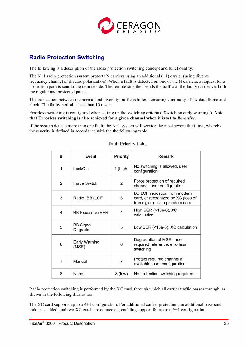
Radio Protection Switching The following is a description of the radio protection switching concept and functionality.
The N+1 radio protection system protects N carriers using an additional (+1) carrier (using diverse frequency channel or diverse polarization). When a fault is detected on one of the N carriers, a request for a protection path is sent to the remote side. The remote side then sends the traffic of the faulty carrier via both the regular and protected paths.
The transaction between the normal and diversity traffic is hitless, ensuring continuity of the data frame and clock. The faulty period is less than 10 msec.
Errorless switching is configured when setting up the switching criteria (“Switch on early warning”). Note that Errorless switching is also achieved for a given channel when it is set to Revertive.
If the system detects more than one fault, the N+1 system will service the most severe fault first, whereby the severity is defined in accordance with the the following table.
Fault Priority Table
# Event Priority Remark
1 LockOut 1 (high) No switching is allowed, user configuration
2 Force Switch 2 Force protection of required channel, user configuration
3 Radio (BB) LOF 3 BB LOF indication from modem card, or recognized by XC (loss of frame), or missing modem card
4 BB Excessive BER 4 High BER (>10e-6), XC calculation
5 BB Signal Degrade 5 Low BER (<10e-6), XC calculation
6 Early Warning (MSE) 6
Degradation of MSE under required reference; errorless switching
7 Manual 7 Protect required channel if available, user configuration
8 None 8 (low) No protection switching required
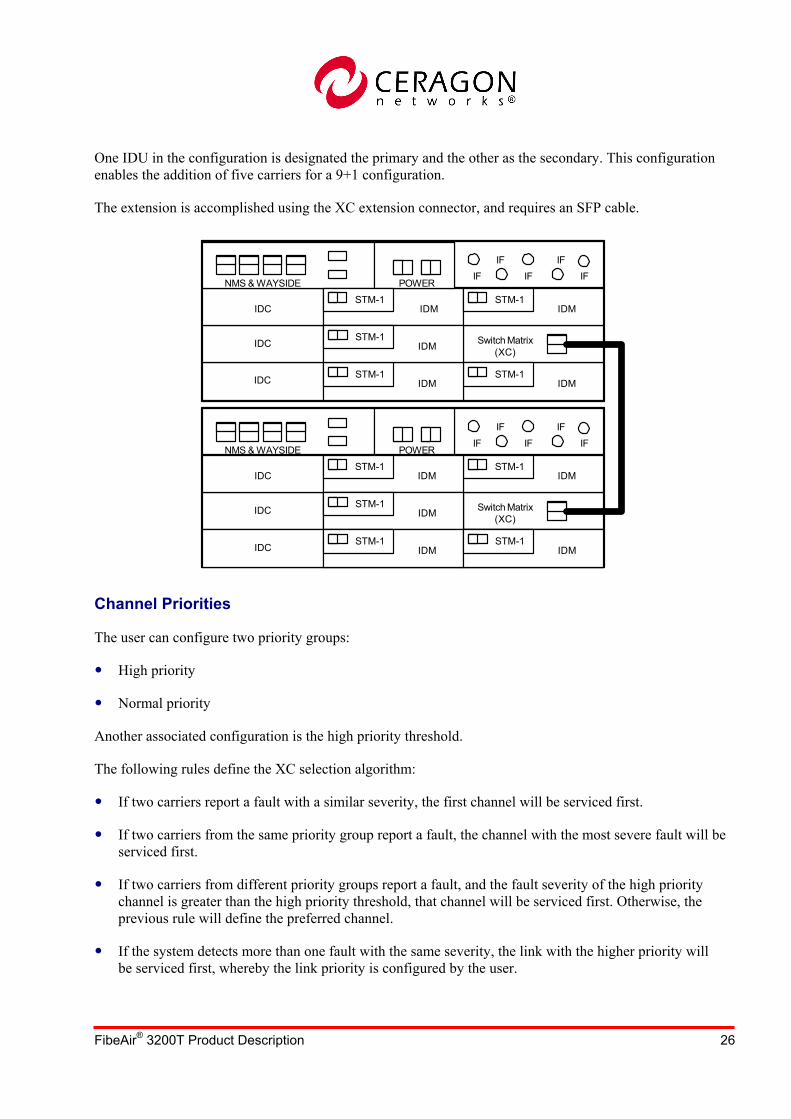
Radio protection switching is performed by the XC card, through which all carrier traffic passes through, as shown in the following illustration.
The XC card supports up to a 4+1 configuration. For additional carrier protection, an additional baseband indoor is added, and two XC cards are connected, enabling support for up to a 9+1 configuration.
FibeAir® 3200T Product Description 26
One IDU in the configuration is designated the primary and the other as the secondary. This configuration enables the addition of five carriers for a 9+1 configuration.
The extension is accomplished using the XC extension connector, and requires an SFP cable.
IFIF
IFIF
IFNMS & WAYSIDE POWER
IDM
Switch Matrix(XC)
IDM
IDMSTM-1
STM-1
STM-1IDC
IDC
IDC IDMSTM-1
IFIF
IFIF
IFNMS & WAYSIDE POWER
Switch Matrix(XC)
IDMSTM-1
IDC
IDC
IDMSTM-1
IDC
IDMSTM-1
IDMSTM-1
IDMSTM-1
IDMSTM-1
Channel Priorities
The user can configure two priority groups:
High priority
Normal priority
Another associated configuration is the high priority threshold.
The following rules define the XC selection algorithm:
If two carriers report a fault with a similar severity, the first channel will be serviced first.
If two carriers from the same priority group report a fault, the channel with the most severe fault will be serviced first.
If two carriers from different priority groups report a fault, and the fault severity of the high priority channel is greater than the high priority threshold, that channel will be serviced first. Otherwise, the previous rule will define the preferred channel.
If the system detects more than one fault with the same severity, the link with the higher priority will be serviced first, whereby the link priority is configured by the user.

FibeAir® 3200T Product Description 27
In revertive mode, the protecting channel returns to transmit the revertive channel once the problem is resolved.
The revertive channel is user-configurable, whereby the user can choose any channel from the group, or extra traffic. Setting a channel to revertive ensures errorless protection for that channel.
After the problem is resolved, the user can configure the time to return to the revertive channel, which can be between 1 and 15 seconds, in 1 second intervals.
The user can select "not protected" for maitenance purposes, or for an N+0 configuration.
Revertive Mode
The user can work in revertive or non-revertive mode. In revertive mode, the system automatically returns the data to its original path when a fault situation is resolved.
In non-revertive mode, the system continues to protect the last channel (errorless protection) until a new higher priority fault occurs.
Upgrade/Downgrade
The user can add a carrier to the N+1 group by inserting the module and setting a configuration command. When a new carrier is added to the N+1 group, the XC receives its status and handles its requests, as with all other carriers.
All cards are hot-swappable (can be inserted during live traffic).
In the RF subrack, a new ICB with its filters and RFU will be chained to the existing ICBs.

FibeAir® 3200T Product Description 28
Link Topologies
The following configurations of 3200T drawers were defined for various topologies. Note that these configurations should be implemented exactly as described, for proper system functionality.
1+1FD
2+1FD
3+1FD
4+1FD

FibeAir® 3200T Product Description 29
Management Ceragon provides state-of-the-art management based on SNMP. Our management applications are written in Java code and can control Ceragon units at both the element and network levels. The applications run on Windows 2000/XP/NT and UNIX systems. CeraView® is Ceragon’s EMS (Element Management System) that enables the operator to perform element configuration, performance monitoring, remote diagnostics, alarm reports, and more. CeraView integrates with different NMS platforms to provide more comprehensive system management.
Example of CeraView Main Window
PolyView™ is Ceragon’s end-to-end network management system that can monitor network element status, provide statistical and inventory reports, download software and configurations to elements, and more. PolyView includes CeraMap™, its powerful and friendly graphical interface. PolyView can also integrate with other NMS platforms to provide more comprehensive network management.
Example of PolyView Window

FibeAir® 3200T Product Description 30
Environmental Conditions Standard Compliance
FibeAir 3200T is fully compliant with the following standards:
Operational
RFU: ETS 300 019-1-4 class 4.1, with an operating temperature range of -50° C to 55° C
Storage and Transportation
Storage: ETS 300 019-2-2 class 1.2, with a maximum temperature limit of +85° C
Transportation: ETS 300 019-2-2 class 2.2
EMC
The system’s EMC and ESD requirements comply with the conditions specified in EN 300 385 [9], for class B.
Safety Conditions Standard Compliance
The system complies with the UL 1950 and EN 60950 safety standards.
FibeAir® 3200T Product Description 31
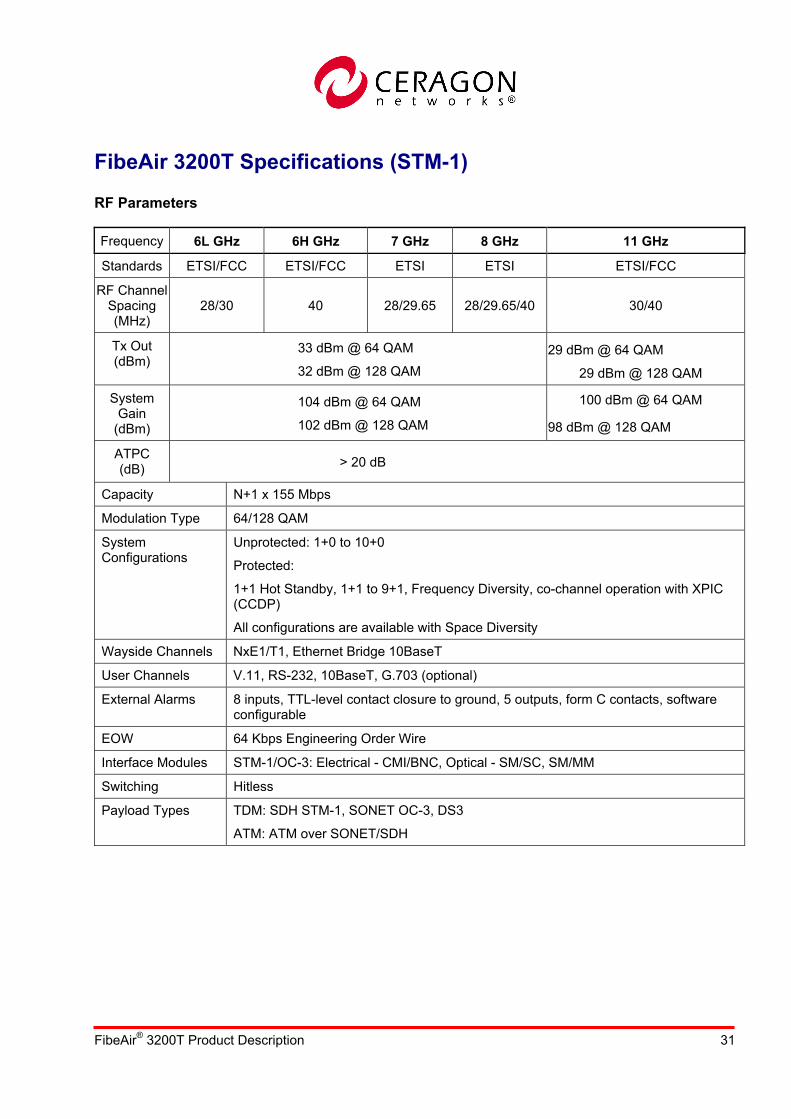
FibeAir 3200T Specifications (STM-1)
RF Parameters
Frequency 6L GHz 6H GHz 7 GHz 8 GHz 11 GHz
Standards ETSI/FCC ETSI/FCC ETSI ETSI ETSI/FCC
RF Channel Spacing (MHz)
28/30 40 28/29.65 28/29.65/40 30/40
Tx Out (dBm)
33 dBm @ 64 QAM
32 dBm @ 128 QAM
29 dBm @ 64 QAM
29 dBm @ 128 QAM
System Gain
(dBm)
104 dBm @ 64 QAM
102 dBm @ 128 QAM
100 dBm @ 64 QAM
98 dBm @ 128 QAM
ATPC (dB) > 20 dB
Capacity N+1 x 155 Mbps
Modulation Type 64/128 QAM
System Configurations
Unprotected: 1+0 to 10+0
Protected:
1+1 Hot Standby, 1+1 to 9+1, Frequency Diversity, co-channel operation with XPIC (CCDP)
All configurations are available with Space Diversity
Wayside Channels NxE1/T1, Ethernet Bridge 10BaseT
User Channels V.11, RS-232, 10BaseT, G.703 (optional)
External Alarms 8 inputs, TTL-level contact closure to ground, 5 outputs, form C contacts, software configurable
EOW 64 Kbps Engineering Order Wire
Interface Modules STM-1/OC-3: Electrical - CMI/BNC, Optical - SM/SC, SM/MM
Switching Hitless
Payload Types TDM: SDH STM-1, SONET OC-3, DS3
ATM: ATM over SONET/SDH
FibeAir® 3200T Product Description 32
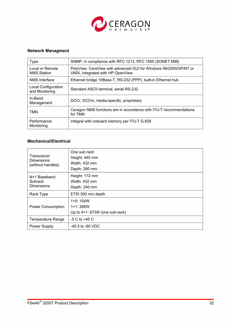
Network Managment
Type SNMP, in compliance with RFC 1213, RFC 1595 (SONET MIB)
Local or Remote NMS Station
PolyView, CeraView with advanced GUI for Windows 98/2000/XP/NT or UNIX, integrated with HP OpenView
NMS Interface Ethernet bridge 10Base-T, RS-232 (PPP), built-in Ethernet hub
Local Configuration and Monitoring Standard ASCII terminal, serial RS-232
In-Band Management DCCr, DCCm, media-specific, proprietary
TMN Ceragon NMS functions are in accordance with ITU-T recommendations for TMN
Performance Monitoring
Integral with onboard memory per ITU-T G.828
Mechanical/Electrical
Transceiver Dimensions (without handles)
One sub rack: Height: 445 mm Width: 432 mm Depth: 280 mm
N+1 Baseband Subrack Dimensions
Height: 172 mm Width: 432 mm Depth: 240 mm
Rack Type ETSI 300 mm depth
Power Consumption 1+0: 154W 1+1: 286W Up to 4+1: 673W (one sub-rack)
Temperature Range -5 C to +45 C
Power Supply -40.5 to -60 VDC

FibeAir® 3200T Product Description 33
Appendix: Frequency Channels
6L GHz (5.85-6.45 GHz)
ITU-R F.383-7 [1-3]
T/R Separation
n (L)
Center Frequency
MHz
n (H)
Center Frequency
MHz 1 5955.00 1 6195.00 2 5995.00 2 6235.00 3 6035.00 3 6275.00 4 6075.00 4 6315.00 5 6115.00 5 6355.00
240
6 6155.00 6 6395.00
ITU-R F.383-7 [0] / FCC 101.147(i8)
T/R Separation
n (L)
Center Frequency
MHz
n (H)
Center Frequency
MHz 1 5945.20 1 6197.24 2 5974.85 2 6226.89 3 6004.50 3 6256.54 4 6034.15 4 6286.19 5 6063.80 5 6315.84 6 6093.45 6 6345.49 7 6123.10 7 6375.14
252.04
8 6152.75 8 6404.79

FibeAir® 3200T Product Description 34
FCC 101.147(i7)
T/R Separation
n (L)
Center Frequency
MHz
n (H)
Center Frequency
MHz
1 5935.32 1 6187.36 2 5945.2 2 6197.24 3 5955.08 3 6207.12 4 5964.97 4 6217.01 5 5974.85 5 6226.89 6 5984.73 6 6236.77 7 5994.62 7 6246.66 8 6004.5 8 6256.54 9 6014.38 9 6266.42
10 6024.27 10 6276.31 11 6034.15 11 6286.19 12 6044.03 12 6296.07 13 6053.92 13 6305.96 14 6063.8 14 6315.84 15 6073.68 15 6325.72 16 6083.57 16 6335.61 17 6093.45 17 6345.49 18 6103.33 18 6355.37 19 6113.22 19 6365.26 20 6123.1 20 6375.14 21 6132.98 21 6385.02 22 6142.87 22 6394.91 23 6152.75 23 6404.79
252.04
24 6162.63 24 6414.67

FibeAir® 3200T Product Description 35
ITU-R F.384-7
T/R Separation
n (L)
Center Frequency
MHz
n (H)
Center Frequency
MHz 1 5955.00 1 6215.00 2 6015.00 2 6275.00 3 6075.00 3 6335.00
260
4 6135.00 4 6395.00
ITU-R F.497-6 [0]
T/R Separation
n (L)
Center Frequency
MHz
n (H)
Center Frequency
MHz 1 5941.00 1 6207.00 2 5969.00 2 6235.00 3 5997.00 3 6263.00 4 6025.00 4 6291.00 5 6053.00 5 6319.00 6 6081.00 6 6347.00 7 6109.00 7 6375.00
266
8 6137.00 8 6403.00
6H GHz (6.45-7.1 GHz)
ITU-R F.384-7
T/R Separation
n (L)
Center Frequency
MHz
n (H)
Center Frequency
MHz 1 6460.00 1 6800.00 2 6500.00 2 6840.00 3 6540.00 3 6880.00 4 6580.00 4 6920.00 5 6620.00 5 6960.00 6 6660.00 6 7000.00 7 6700.00 7 7040.00
340
8 6740.00 8 7080.00

FibeAir® 3200T Product Description 36
FCC 101.147(k7)
T/R Separation
n (L)
Center Frequency
MHz
n (H)
Center Frequency
MHz 1 6545 1 6715 2 6555 2 6725 3 6565 3 6735
170
4 6585 4 6745 1 6595 1 6755 2 6605 2 6765 3 6615 3 6775 4 6625 4 6785 5 6635 5 6795 6 6645 6 6805 7 6655 7 6815 8 6665 8 6825 9 6675 9 6835 10 6685 10 6845 11 6695 11 6855
160
12 6705 12 6865 40 1 6535 1 6575
7 GHz (7.1-7.9 GHz)
ITU-R 385-7 [1]
T/R Separation
n (L)
Center Frequency
MHz
n (H)
Center Frequency
MHz 1 7442 1 7596 2 7470 2 7624 3 7498 3 7652 4 7526 4 7680
154A
5 7554 5 7708
FibeAir® 3200T Product Description 37
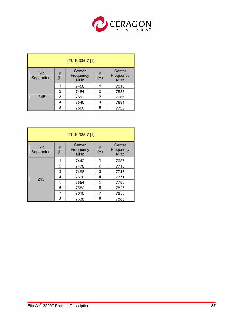
ITU-R 385-7 [1]
T/R Separation
n (L)
Center Frequency
MHz
n (H)
Center Frequency
MHz 1 7456 1 7610 2 7484 2 7638 3 7512 3 7666 4 7540 4 7694
154B
5 7568 5 7722
ITU-R 385-7 [1]
T/R Separation
n (L)
Center Frequency
MHz
n (H)
Center Frequency
MHz 1 7442 1 7687 2 7470 2 7715 3 7498 3 7743 4 7526 4 7771 5 7554 5 7799 6 7582 6 7827 7 7610 7 7855
245
8 7638 8 7883

FibeAir® 3200T Product Description 38
ITU-R 385-7 [0]
T/R Separation
n (L)
Center Frequency
MHz
n (H)
Center Frequency
MHz 1 7138.5 1 7299.5 2 7166.5 2 7327.5 3 7194.5 3 7355.5 4 7222.5 4 7383.5 5 7250.5 5 7411.5
11 7145.5 11 7306.5 12 7173.5 12 7334.5 13 7201.5 13 7362.5 14 7229.5 14 7390.5 21 7152.5 21 7313.5 22 7180.5 22 7341.5 23 7208.5 23 7369.5 24 7236.5 24 7397.5 31 7159.5 31 7320.5 32 7187.5 32 7348.5 33 7215.5 33 7376.5
161A
34 7243.5 34 7404.5
ITU-R 385-7 [0]
T/R Separation
n (L)
Center Frequency
MHz
n (H)
Center Frequency
MHz 1 7263.5 1 7424.5 2 7291.5 2 7452.5 3 7319.5 3 7480.5 4 7347.5 4 7508.5 5 7375.5 5 7536.5
11 7270.5 11 7431.5 12 7298.5 12 7459.5 13 7326.5 13 7487.5 14 7354.5 14 7515.5 21 7277.5 21 7438.5 22 7305.5 22 7466.5 23 7333.5 23 7494.5 24 7361.5 24 7522.5 31 7284.5 31 7445.5 32 7312.5 32 7473.5 33 7340.5 33 7501.5
161B
34 7368.5 34 7529.5

FibeAir® 3200T Product Description 39
ITU-R 385-7 [0]
T/R Separation
n (L)
Center Frequency
MHz
n (H)
Center Frequency
MHz 1 7438.5 1 7599.5 2 7466.5 2 7627.5 3 7494.5 3 7655.5 4 7522.5 4 7683.5 5 7550.5 5 7711.5
11 7445.5 11 7606.5 12 7473.5 12 7634.5 13 7501.5 13 7662.5 14 7529.5 14 7690.5 21 7452.5 21 7613.5 22 7480.5 22 7641.5 23 7508.5 23 7669.5 24 7536.5 24 7697.5 31 7459.5 31 7620.5 32 7487.5 32 7648.5 33 7515.5 33 7676.5
161C
34 7543.5 34 7704.5
ITU-R 385-7 [0]
T/R Separation
n (L)
Center Frequency
MHz
n (H)
Center Frequency
MHz 1 7563.5 1 7724.5 2 7591.5 2 7752.5 3 7619.5 3 7780.5 4 7647.5 4 7808.5 5 7675.5 5 7836.5
11 7570.5 11 7731.5 12 7598.5 12 7759.5 13 7626.5 13 7787.5 14 7654.5 14 7815.5 21 7577.5 21 7738.5 22 7605.5 22 7766.5 23 7633.5 23 7794.5 24 7661.5 24 7822.5 31 7584.5 31 7745.5 32 7612.5 32 7773.5 33 7640.5 33 7801.5
161D
34 7668.5 34 7829.5
FibeAir® 3200T Product Description 40
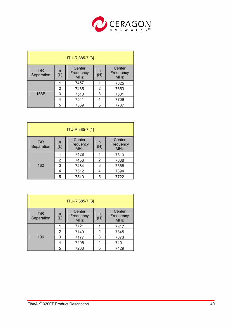
ITU-R 385-7 [3]
T/R Separation
n (L)
Center Frequency
MHz
n (H)
Center Frequency
MHz 1 7457 1 7625 2 7485 2 7653 3 7513 3 7681 4 7541 4 7709
168B
5 7569 5 7737
ITU-R 385-7 [1]
T/R Separation
n (L)
Center Frequency
MHz
n (H)
Center Frequency
MHz 1 7428 1 7610 2 7456 2 7638 3 7484 3 7666 4 7512 4 7694
182
5 7540 5 7722
ITU-R 385-7 [3]
T/R Separation
n (L)
Center Frequency
MHz
n (H)
Center Frequency
MHz 1 7121 1 7317 2 7149 2 7345 3 7177 3 7373 4 7205 4 7401
196
5 7233 5 7429

FibeAir® 3200T Product Description 41
ITU-R 385-7 [4]
T/R Separation
n (L)
Center Frequency
MHz
n (H)
Center Frequency
MHz 1 7442 1 7687 2 7470 2 7715 3 7498 3 7743 4 7526 4 7771 5 7554 5 7799 6 7582 6 7827 7 7610 7 7855
245
8 7638 8 7883
8 GHz (7.8-8.5 GHz)
ITU-R 386-6 [4]
T/R Separation
n (L)
Center Frequency
MHz
n (H)
Center Frequency
MHz 1 7926 1 8192 2 7954 2 8220 3 7982 3 8248 4 8010 4 8276 5 8038 5 8304 6 8066 6 8332 7 8094 7 8360
266
8 8122 8 8388

FibeAir® 3200T Product Description 42
ITU-R 386-6 [1]
T/R Separation
n (L)
Center Frequency
MHz
n (H)
Center Frequency
MHz 1 7747.70 1 8059.02 2 7777.35 2 8088.67 3 7807.00 3 8118.32 4 7836.65 4 8147.97 5 7866.30 5 8177.62 6 7895.95 6 8207.27 7 7925.60 7 8236.92
311.32A
8 7955.25 8 8266.57
ITU-R 386-6 [1]
T/R Separation
n (L)
Center Frequency
MHz
n (H)
Center Frequency
MHz 1 7732.875 1 8044.195 2 7762.525 2 8073.845 3 7792.175 3 8103.495 4 7821.825 4 8133.145 5 7851.475 5 8162.795 6 7881.125 6 8192.445 7 7910.775 7 8222.095
311.32B
8 7940.425 8 8251.745
ITU-R 386-6 [3]
T/R Separation
n (L)
Center Frequency
MHz
n (H)
Center Frequency
MHz 1 8293 1 8412 2 8307 2 8426 3 8321 3 8440 4 8335 4 8454 5 8349 5 8468
119
6 8363 6 8482
FibeAir® 3200T Product Description 43
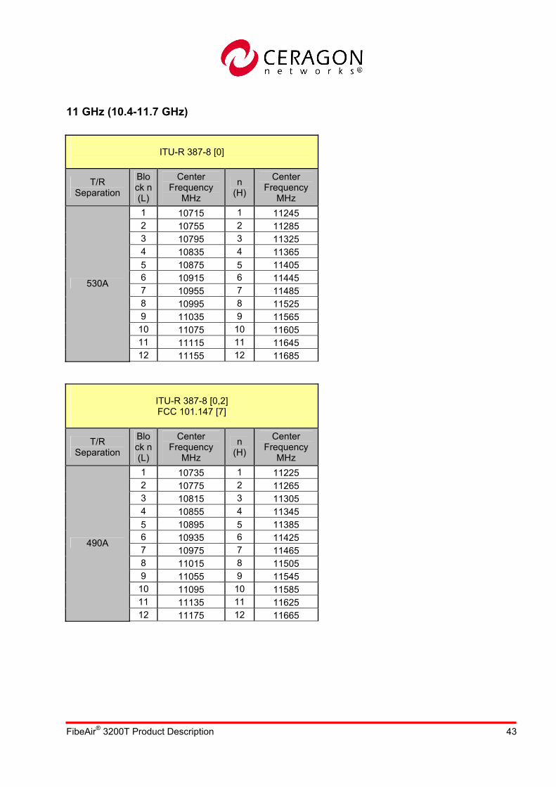
11 GHz (10.4-11.7 GHz)
ITU-R 387-8 [0]
T/R Separation
Block n (L)
Center Frequency
MHz
n (H)
Center Frequency
MHz 1 10715 1 11245 2 10755 2 11285 3 10795 3 11325 4 10835 4 11365 5 10875 5 11405 6 10915 6 11445 7 10955 7 11485 8 10995 8 11525 9 11035 9 11565 10 11075 10 11605 11 11115 11 11645
530A
12 11155 12 11685
ITU-R 387-8 [0,2] FCC 101.147 [7]
T/R Separation
Block n (L)
Center Frequency
MHz
n (H)
Center Frequency
MHz 1 10735 1 11225 2 10775 2 11265 3 10815 3 11305 4 10855 4 11345 5 10895 5 11385 6 10935 6 11425 7 10975 7 11465 8 11015 8 11505 9 11055 9 11545 10 11095 10 11585 11 11135 11 11625
490A
12 11175 12 11665

FibeAir® 3200T Product Description 44
CEPT/12-6 E
T/R Separation
Block n (L)
Center Frequency
MHz
n (H)
Center Frequency
MHz 1 10715 1 11205 2 10755 2 11245 3 10795 3 11285 4 10835 4 11325 5 10875 5 11365 6 10915 6 11405 7 10955 7 11445 8 10995 8 11485 9 11035 9 11525 10 11075 10 11565
490B
11 11115 11 11605
ITU-R 387-8 [6]
T/R Separation
Block n (L)
Center Frequency
MHz
n (H)
Center Frequency
MHz 1 10730 1 11250 2 10790 2 11310 3 10850 3 11370 4 10910 4 11430 5 10970 5 11490 6 11030 6 11550 7 11090 7 11610
520A
8 11150 8 11670

FibeAir® 3200T Product Description 45
ITU-R 387-8 [6]
T/R Separation
Block n (L)
Center Frequency
MHz
n (H)
Center Frequency
MHz 500 1 10715 1 11215
2 10755 2 11245 3 10795 3 11285 4 10835 4 11325 5 10875 5 11365 6 10915 6 11405 7 10955 7 11445 8 10995 8 11485 9 11035 9 11525 10 11075 10 11565 11 11115 11 11605
490C
12 11155 12 11645 500 13 11185 13 11685


