29
FIBER OPTIC GYRO / THEORY & APPLICATIONS Yves PATUREL, MELAHA Alexandria, September 2014

FIBER OPTIC GYRO / THEORY &
APPLICATIONS
Yves PATUREL, MELAHA Alexandria, September 2014

2
Melaha 2014 Alexandria
Contents
Long term navigation key parameter
FOG principle
Key orders of magnitude
Key features
Comparison with other technologies
IXBLUE catalog examples
3
Melaha 2014 Alexandria
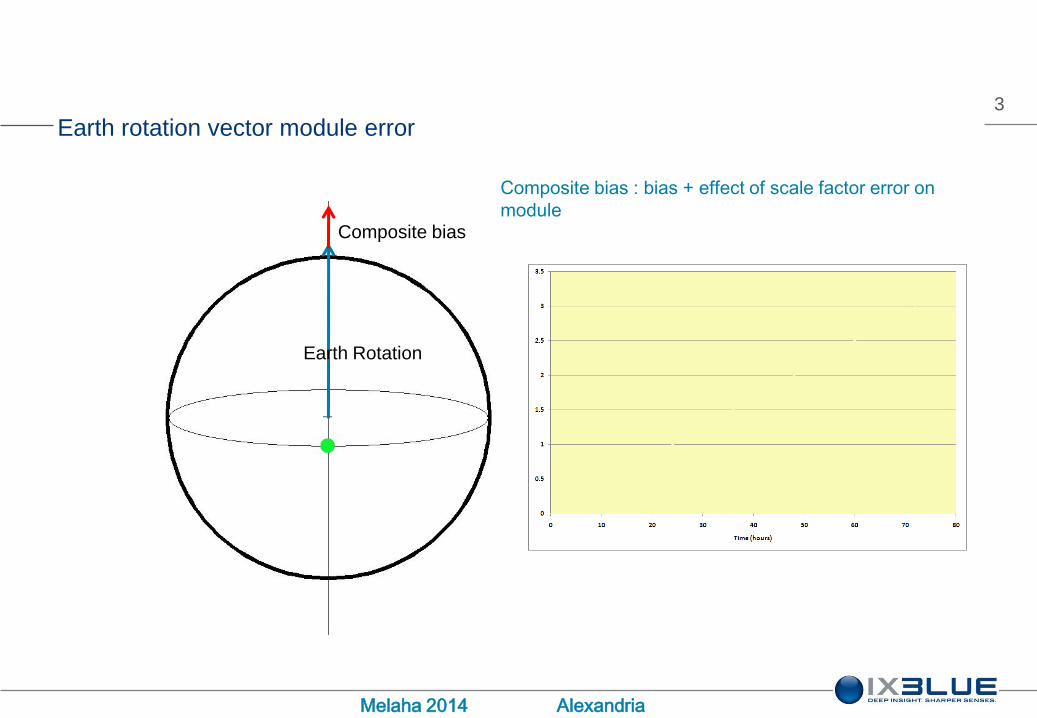
Earth rotation vector module error
Composite bias : bias + effect of scale factor error on
moduleComposite bias
Earth Rotation

4
Melaha 2014 Alexandria
Earth rotation vector module error
Composite bias : bias + effect of scale factor error on
moduleComposite bias
Earth Rotation

5
Melaha 2014 Alexandria
Longitude error during a 60 hour navigation
6
Melaha 2014 Alexandria
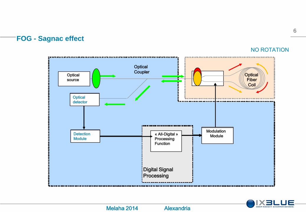
FOG - Sagnac effect
Digital Signal
Processing
COIOptical
source
Optical
Coupler
« All-Digital »
Processing
Function
Modulation
Module
Optical Fiber
Coil
Optical
detector
Detection
Module
Digital Signal
Processing
« All-Digital »
Processing
Function
Modulation
Module
Optical
detector
Detection
Module
NO ROTATION

7
Melaha 2014 Alexandria
FOG - Sagnac effect
Digital Signal
Processing
COIOptical
source
Optical
Coupler
« All-Digital »
Processing
Function
Modulation
Module
Optical Fiber
Coil
Optical
detector
Detection
Module
Digital Signal
Processing
« All-Digital »
Processing
Function
Modulation
Module
Optical
detector
Detection
Module

8
Melaha 2014 Alexandria
Response of the interferometer
9
Melaha 2014 Alexandria
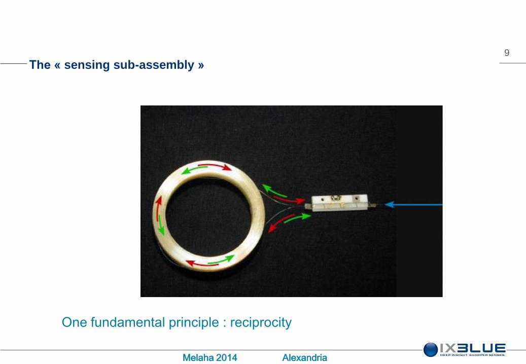
The « sensing sub-assembly »
One fundamental principle : reciprocity
10
Melaha 2014 Alexandria
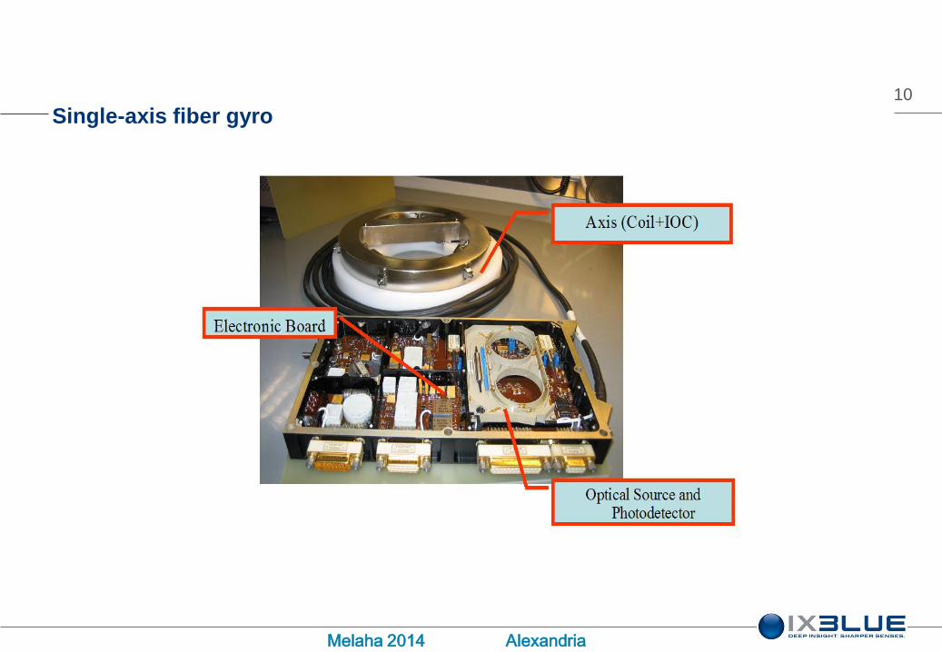
Single-axis fiber gyro
11
Melaha 2014 Alexandria
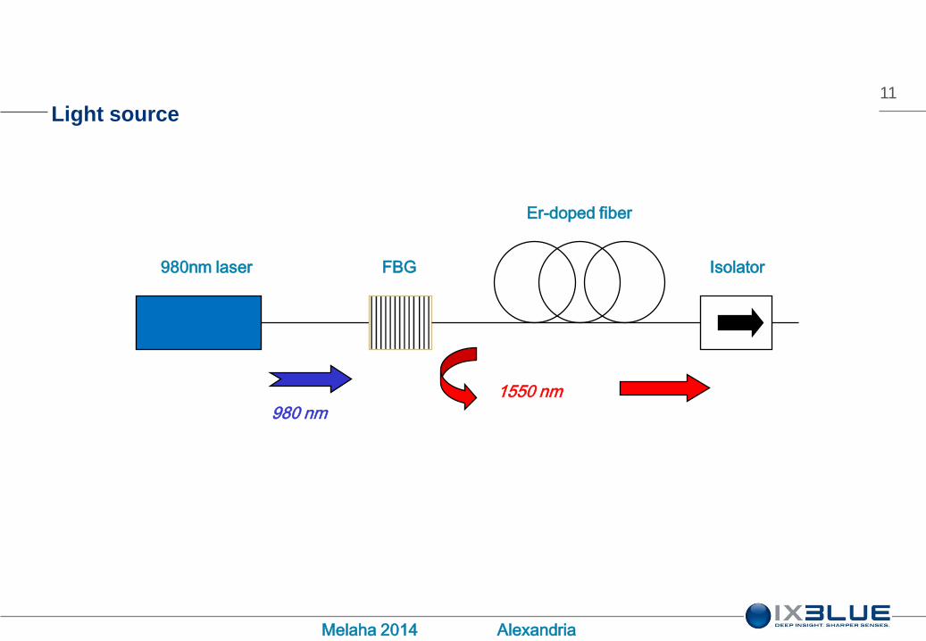
Light source
980nm laser FBG
Er-doped fiber
Isolator
980 nm
1550 nm
12
Melaha 2014 Alexandria
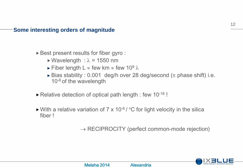
Some interesting orders of magnitude
Best present results for fiber gyro :
Wavelength : l = 1550 nm
Fiber length L few km few 109 l
Bias stability : 0.001 deg/h over 28 deg/second (p phase shift) i.e. 10-8 of the wavelength
Relative detection of optical path length : few 10-18 !
With a relative variation of 7 x 10⁻⁶ / ºC for light velocity in the silica fiber !
RECIPROCITY (perfect common-mode rejection)

13
Melaha 2014 Alexandria
Actual configuration of a fiber gyro
Polarization-preserving fiber coil with typically 100 m to 10 km (manufactured by iXBlue).
Proton-exchanged LiNbO3 integrated-optic circuit very high polarizer rejection (manufactured by
iXBlue).
Y-junction and pair of push-pull low-voltage phase modulators.
Broad-spectrum source : unpolarized erbium ASE source for best performance (manufactured by
iXBlue).
All-digital processing electronics (invented by iXblue).
Fiber
Coil
Broadband Light
Source
Coupler
Multi-function
IOC
Detector
A
/
D
Digital
LogicsD
/
A
Rotation signal

14
Melaha 2014 Alexandria
FOG comparison with other technologies
FOG has no lock-in zone
Always true in open-loop design.
In closed loop design, no dead zone in principle, but a “dead zone “ may appear
if electronics design is not perfect (cross talk between modulation & detection
chains)
In RLG (Ring Laser Gyro), lock-in is by-passed with dithering : this increases
ARW, and provides acoustic noise
FOG has not (yet ?) reached a performance limit , while RLG faces a “non
reciprocity”

15
Melaha 2014 Alexandria
FOG is easily scalable
QUADRANSOCTANS
AHRS
PHINS
INS
MARINS
INS
IMU 50 IMU 90 IMU 120 IMU 200
Average Diameter (mm) 45 68 94 171
Bias Stability* (°/h) 0,05 0,025 0,01 0,001
Typical ARW (10-4 °/√h) 60 35 10 2
* Bias stability over the temperature range, -10 to +80°C à 1 σ
16
Melaha 2014 Alexandria
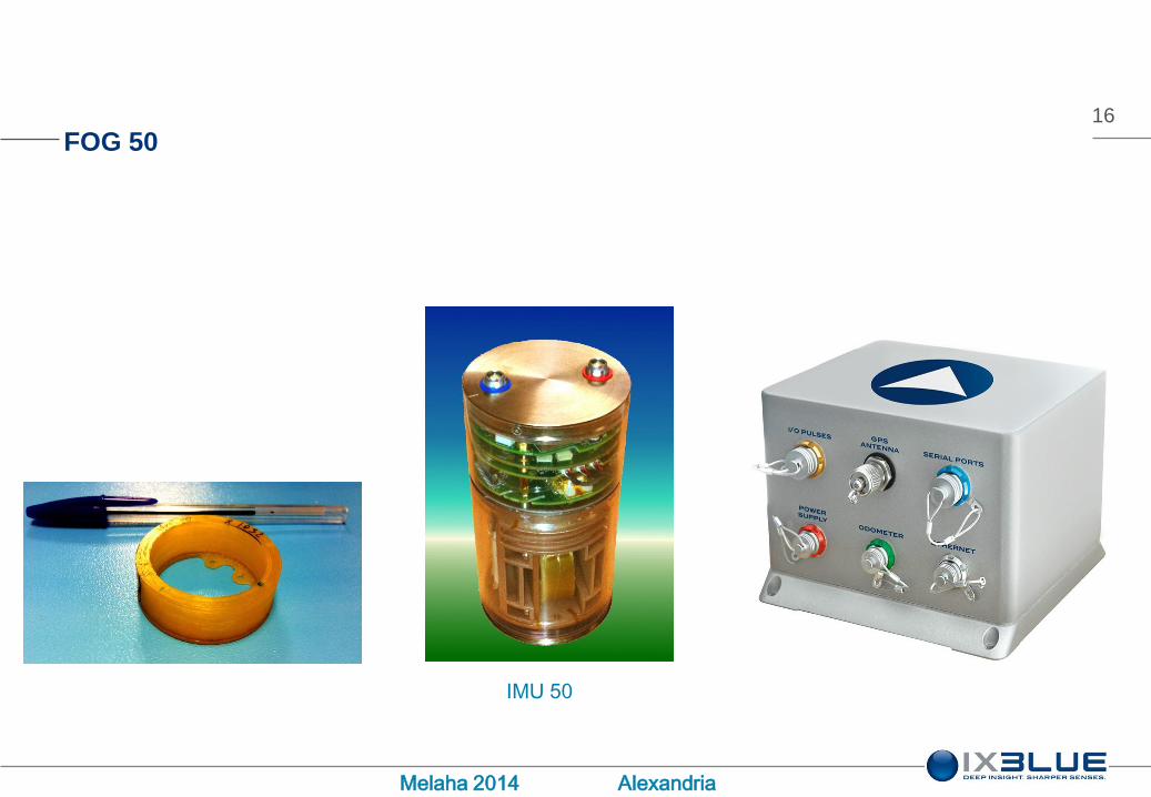
FOG 50
IMU 50

17
Melaha 2014 Alexandria
FOG 50 APPLICATIONS
Marine and Navy IMO gyrocompass
Land survey, stabilization
Military land navigation
Airborne survey

18
Melaha 2014 Alexandria
FOG 90
OCTANS
ADVANS
LANDINS

19
Melaha 2014 Alexandria
FOG 90 APPLICATIONS
Navy & marine gyrocompass
Land survey
Military land navigation
Artillery (qualified on 105 mm gun)

20
Melaha 2014 Alexandria
FOG 120
PHINS
ASTRIX 120
ADVANS
21
Melaha 2014 Alexandria
FOG 120 APPLICATIONS
Navy & Marine navigation system
Land military navigation
Artillery (on 155 mm gun)
Airborne survey

22
Melaha 2014 Alexandria
FOG 200
MARINS
ASTRIX 200

23
Melaha 2014 Alexandria
FOG 200 APPLICATIONS
Submarine navigation and high-end surface vessels

24
Melaha 2014 Alexandria

25
Melaha 2014 Alexandria
Construction
complexity
decreases
Computing
complexity
increases
26
Melaha 2014 Alexandria

27
Melaha 2014 Alexandria
28
Melaha 2014 Alexandria
CONCLUSION
FOG technology is very reliable, very robust and has extremely long life time
44 FOG axes are on orbit around Earth cumulating more than 9300000
hours (106 years) without failure
FOG technology provides navigation for many marine applications :
Reliable and no maintenance gyrocompass,
Low power consumption inertial navigation system (especially suitable for AUV)
High performance navigation system for surface vessels and submarines

29
Melaha 2014 Alexandria
Come and visit us at our booth in exhibition hall
شكرا


