Optical fiber is a good vehiclefor high-speed data trans-mission as long as light trans-
mission is efficient — even acrossconnector assemblies. This trans-lates to a need to polish connectorend faces to optimize performance.Increasingly, with the adop-tion of newer fiber configura-tions, as well as ever-tighten-ing specifications, automationof the polishing process is be-coming a necessity.
Early physical contact con-nectors required sphericalforming of their flat end facesas part of the polishing proce-dure. These traditional tech-niques involved a four-stepprocess: epoxy removal, fer-rule forming, and preliminaryand final polishing. Thesesteps used aggressive materi-als for epoxy removal and fer-rule forming, generally ac-complished with diamond pol-ishing films.
Now, however, because al-most all connectors are man-ufactured with a pre-radiusedend face, the polishing processhas developed into a sequenceof epoxy removal, followed by
rough, intermediate and final pol-ishing cycles. One goal is to avoidexcessive disruption of the sphericalsurface, while still producing a goodmating surface. Polished fiber opticconnectors must then conform to arange of performance and geometry-
based acceptance criteria.Polishing specifications for fiber
connectors fall into two categoriesrelated to performance and end-facegeometry. Perhaps the most criticalmeasures of polished end function-ality are backreflection and insertion
loss specifications. The lat-ter is the amount of opticalpower lost at the interfacebetween the connectors,usually caused by fiber mis-alignment, separation be-tween connections (the airgap) and the finish qualityof each connector end. Thisloss is a function of both thepolishing equipment and thetechnique used. The currentstandard loss specificationis less than 0.5 dB, but lessthan 0.3 dB is increasinglyspecified.
Connector typesBackreflection is the light
reflected back through thefiber toward the source. High backreflection cantranslate to signal distortionand, therefore, bit errors insystems with high datatransfer rates. Common con-nector categories include su-perphysical contact, withbackreflection of 245 dB; ul-traphysical contact, withbackreflection of ≤255 dB;and angled physical contact,which has an 8° angle on the end face and backre-flection of ≤265 dB. Al-though acceptable backre-flection will vary dependingon the application, end user
To ensure fast, error-free data transmission, connectors must
conform to acceptance criteria related to backreflection and
insertion loss, as well as to end-face geometry specifications.
by Robert Rubin, Ultra Tec Mfg. Inc.
8°
Fiber optic connectors areoften specified with a backreflection of less than255 dB and insertion loss of less than 0.3 dB. Anotheroption is ultraphysical contact,with an angled end face.
Key geometric acceptance criteriainclude apex offset, radius of curva-ture, and fiber undercut or protru-sion. All of these affect performanceto some degree. For example, apexoffset is the measured distance be-tween the center of the fiber and theapex or highest point on the spher-ical surface at the connector endface. An excessive offset will con-tribute to high insertion loss andbackreflection readings. Current ac-cepted offset is less than 50 µm.
The radius of curvature measuresthe radius generated on a connectorend face. This measurement mustbe such that when mated with an-other connector, most of the com-pression is applied to the materialsurrounding the fiber (also called fer-rule absorption). The typical speci-fication range is now 8 to 25 mm. Ingeneral, the pre-radius on ferrulesis maintained during polishing byusing a weight to apply pressure be-tween the connector and a resilientpolishing surface, or by setting com-pression dimensionally. The harderthe polishing surface, the larger theresultant connector radius.
Optimizing compressionA proper radius, combined with
an acceptable fiber undercut, willoptimize fiber-to-connector com-pression. The undercut measureshow far the fiber is recessed insidea connector ferrule, but it also maybe possible for a fiber to protrudeabove the ferrule. Both conditionsdirectly result from the polishingprocess and can be measured withan interferometer.
Excessive fiber undercut/protru-sion is usually specified as greaterthan ±50 nm. When connectors aremated, the ferrule material sur-rounding the fiber compresses, al-lowing fibers with an acceptable un-dercut or protrusion to make con-tact. Inadequate contact can lead toan air gap as well as unacceptablebackreflection and insertion loss.
Today there are several types ofconnectorized fibers, the most com-mon of which are 2.5 mm, 1.25 mmand multifiber. To ensure a propermating surface, connector end facesmust first be air-polished. This willbe followed by a sequence of polish-ing steps that depend on the type ofconnector, the backreflection and theinsertion loss specifications, as listed
below for 2.5-mm connectors:Multimode. Used in less-demand-
ing applications, this three-stepprocess would involve 5-µm siliconcarbide, 1-µm diamond and a finalpolish film.
Single-mode ultraphysical contact.Probably the most common polished2.5-mm connector, this offers fairlygood backreflection of less than 255dB, without the need to add an angleto the end face. The typical sequenceincludes a 5-µm silicon carbide pass,polishing with 3-µm aluminum oxideand 1-µm diamond, and a final pol-ishing film.
Single-mode angled physical con-tact. This offers the best backreflec-tion performance at less than 265dB; however, there is an added pro-cessing cost because of the additionof the 8° angle to deflect backreflec-tion to that level. This process wouldinvolve polishing with 15-µm siliconcarbide, passes with 3-µm aluminumoxide and 1-µm diamond, and a finalpolishing film.
Regardless of the connector type,most polishing sequences begin withaggressive materials, including sili-con carbide to remove epoxy and di-amond lapping films for beginningand intermediate polishing. Theseremove both surrounding materialand fiber at the same rate. The lastpolishing step, however, requires aless aggressive material, such as sil-icon dioxide, to attack only the fiber.Using a material for final polishingthat is too aggressive could lead toexcessive undercut. The wrong final-polish material also could cause ex-cessive protrusion, leading to fiberchipping and cracking during theconnector mating process.
The scrap rate will vary, dependingon the polishing equipment and thematerial being polished. For instance,a machine that produces poor end-face geometry will almost always
Polishing Fiber Connectors
Interference Fringes
Apex
Fiber
Center of Fiber
SCALE
Perfect Apex Offset Acceptable Apex Offset
Fail/Reject
Interferometric analysis is used tomeasure the apex offset of fiberoptic connector end faces. An offsetof 50 nm or higher can limit fiber-to-fiber contact, increasing insertion loss.
generate unacceptable loss. In gen-eral, yield should exceed 95 percent.If it doesn’t, companies should ex-amine the complete process moreclosely, not just the polishing. Are
components being assembled cor-rectly? Are the connectors made withquality material?
Cleanliness also can affect yield.Thorough cleaning of connectors be-
tween processing steps, as well asrapid changing of polishing plates,can help reduce cross contamina-tion and subsequent backreflectionproblems.
Polishing Fiber Connectors
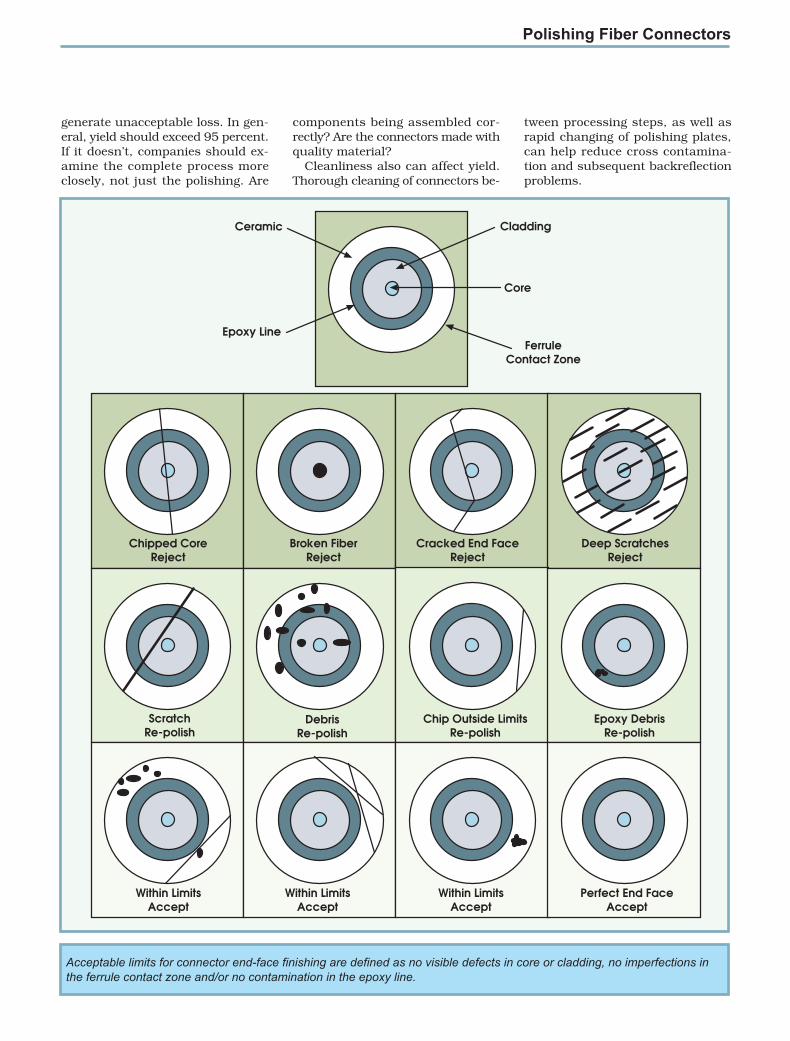
Cladding
Core
FerruleContact Zone
Ceramic
Epoxy Line
Chipped CoreReject
Broken FiberReject
Cracked End FaceReject
Deep ScratchesReject
ScratchRe-polish
DebrisRe-polish
Chip Outside LimitsRe-polish
Epoxy DebrisRe-polish
Within LimitsAccept
Within LimitsAccept
Within LimitsAccept
Perfect End FaceAccept
Acceptable limits for connector end-face finishing are defined as no visible defects in core or cladding, no imperfections inthe ferrule contact zone and/or no contamination in the epoxy line.