64
» Wide portfolio range » Long operational life » Easy to install and set up FIBER-OPTIC SENSORS High precision in small spaces
» W i d e p o r t f o l i o r a n g e» L o n g o p e r a t i o n a l l i f e
» E a s y t o i n s t a l l a n d s e t u p
FIBER-OPTIC SENSORS H i g h p r e c i s i o n i n s m a l l s p a c e s
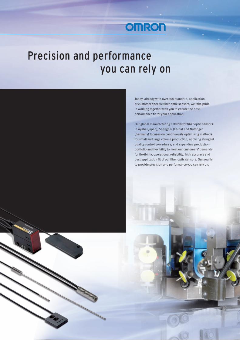
Today, already with over 500 standard, application
or customer specific fiber optic sensors, we take pride
in working together with you to ensure the best
performance fit for your application.
Our global manufacturing network for fiber optic sensors
in Ayabe (Japan), Shanghai (China) and Nufringen
(Germany) focuses on continuously optimising methods
for small and large volume production, applying stringent
quality control procedures, and expanding production
portfolio and flexibility to meet our customers’ demands
for flexibility, operational reliability, high accuracy and
best application fit of our fiber optic sensors. Our goal is
to provide precision and performance you can rely on.
Precision and performance you can rely on
For over 30 years OMRON has been a supplier of fiber
optic solutions to leading manufacturers, especially
in the semiconductor, the consumer electronics
and the car electronics industry, as well as for food
packaging and small plastic parts production.
The requirements for fiber optic solutions can be
very demanding particularly for applications with
extreme temperatures and aggressive chemicals
for applications requiring highest precision in
combination with limited mounting space or for
applications requiring the reliable detection of
a wide range of objects with different materials,
shapes or colours.
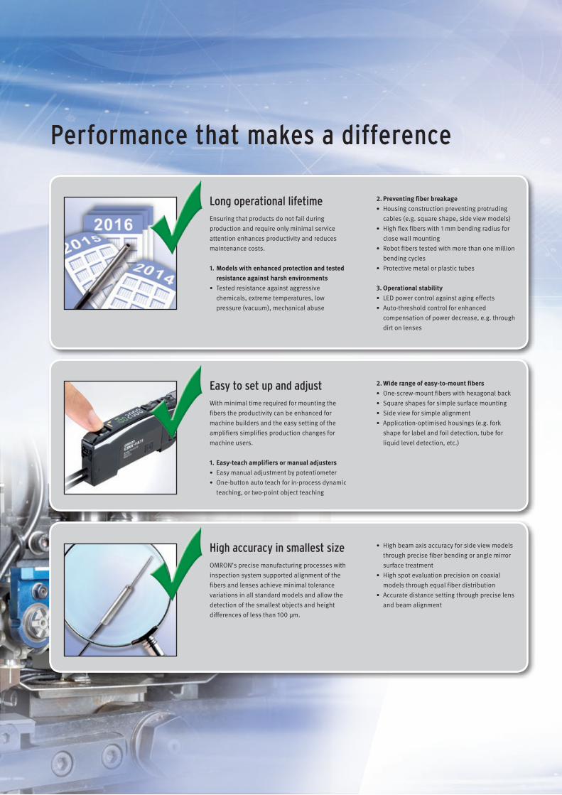
Performance that makes a difference
Long operational lifetime Ensuring that products do not fail during production and require only minimal service attention enhances productivity and reduces maintenance costs.
1. Models with enhanced protection and tested resistance against harsh environments
• Tested resistance against aggressive chemicals, extreme temperatures, low pressure (vacuum), mechanical abuse
2. Preventing fiber breakage • Housing construction preventing protruding
cables (e.g. square shape, side view models) • High flex fibers with 1 mm bending radius for
close wall mounting • Robot fibers tested with more than one million
bending cycles • Protective metal or plastic tubes
3. Operational stability • LED power control against aging effects • Auto-threshold control for enhanced
compensation of power decrease, e.g. through dirt on lenses
Easy to set up and adjust With minimal time required for mounting the fibers the productivity can be enhanced for machine builders and the easy setting of the amplifiers simplifies production changes for machine users.
1. Easy-teach amplifiers or manual adjusters • Easy manual adjustment by potentiometer • One-button auto teach for in-process dynamic
teaching, or two-point object teaching
2. Wide range of easy-to-mount fibers • One-screw-mount fibers with hexagonal back • Square shapes for simple surface mounting • Side view for simple alignment • Application-optimised housings (e.g. fork
shape for label and foil detection, tube for liquid level detection, etc.)
High accuracy in smallest size OMRON’s precise manufacturing processes with inspection system supported alignment of the fibers and lenses achieve minimal tolerance variations in all standard models and allow the detection of the smallest objects and height differences of less than 100 μm.
• High beam axis accuracy for side view models through precise fiber bending or angle mirror surface treatment
• High spot evaluation precision on coaxial models through equal fiber distribution
• Accurate distance setting through precise lens and beam alignment
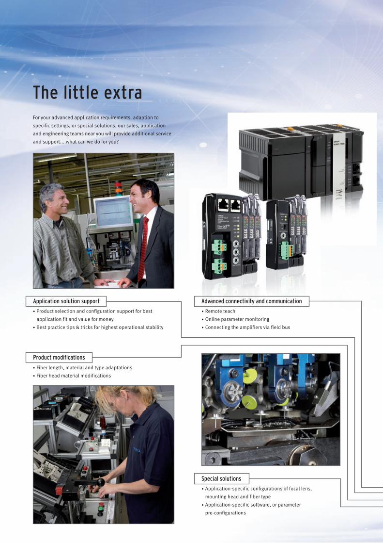
Advanced connectivity and communication Application solution support
Product modifications
Special solutions
• Product selection and configuration support for best
application fit and value for money
• Best practice tips & tricks for highest operational stability
The little extra For your advanced application requirements, adaption to
specific settings, or special solutions, our sales, application
and engineering teams near you will provide additional service
and support....what can we do for you?
• Remote teach
• Online parameter monitoring
• Connecting the amplifiers via field bus
• Fiber length, material and type adaptations
• Fiber head material modifications
• Application-specific configurations of focal lens,
mounting head and fiber type
• Application-specific software, or parameter
pre-configurations
slow
m
ed fast very fast
400 °C
400 °C
slow
m
ed fast very fast
400 °C
400 °C
slow
m
ed fast very fast
400 °C
400 °C
slow
m
ed fast very fast
400 °C
400 °C
slow
m
ed fast very fast
400 °C
400 °C
slow
m
ed fast very fast
400 °C
400 °C
slow
m
ed fast very fast
400 °C
400 °C
slow
m
ed fast very fast
400 °C400 °C
slow
m
ed fast very fast
400 °C
400 °C
slow
m
ed fast very fast
400 °C
400 °Cslow
m
ed fast very fast
400 °C
400 °C
Infrared LED
8
16
20
26
27
31
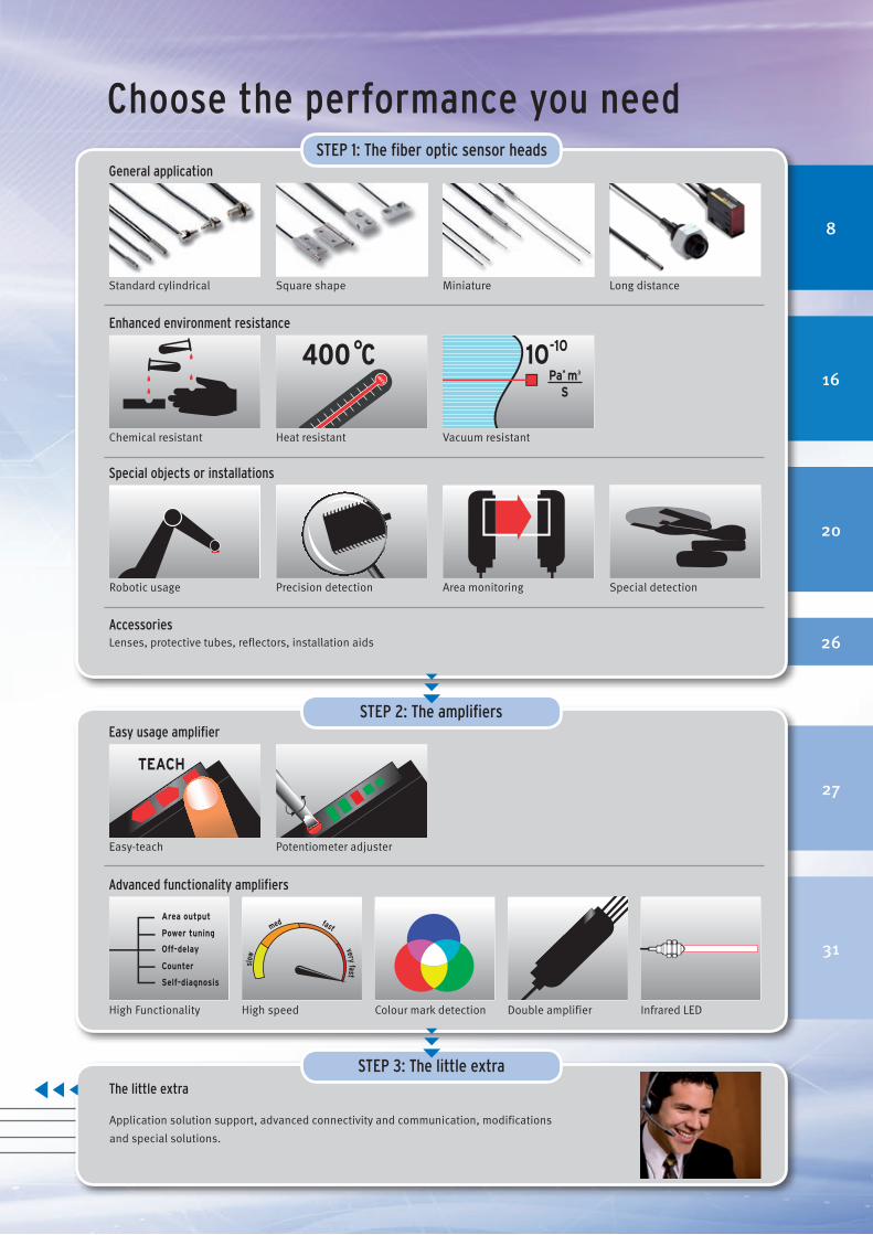
Choose the performance you need
General application
Standard cylindrical Square shape Miniature Long distance
Enhanced environment resistance
Heat resistant Chemical resistant Vacuum resistant
Special objects or installations
Area monitoring
Accessories
Easy usage amplifier
Easy-teach Potentiometer adjuster
Advanced functionality amplifiers
Robotic usage Precision detection Special detection
High Functionality High speed Colour mark detection Double amplifier
STEP 1: The fiber optic sensor heads
STEP 2: The amplifiers
Lenses, protective tubes, reflectors, installation aids
The little extra
Application solution support, advanced connectivity and communication, modifications
and special solutions.
STEP 3: The little extra
6
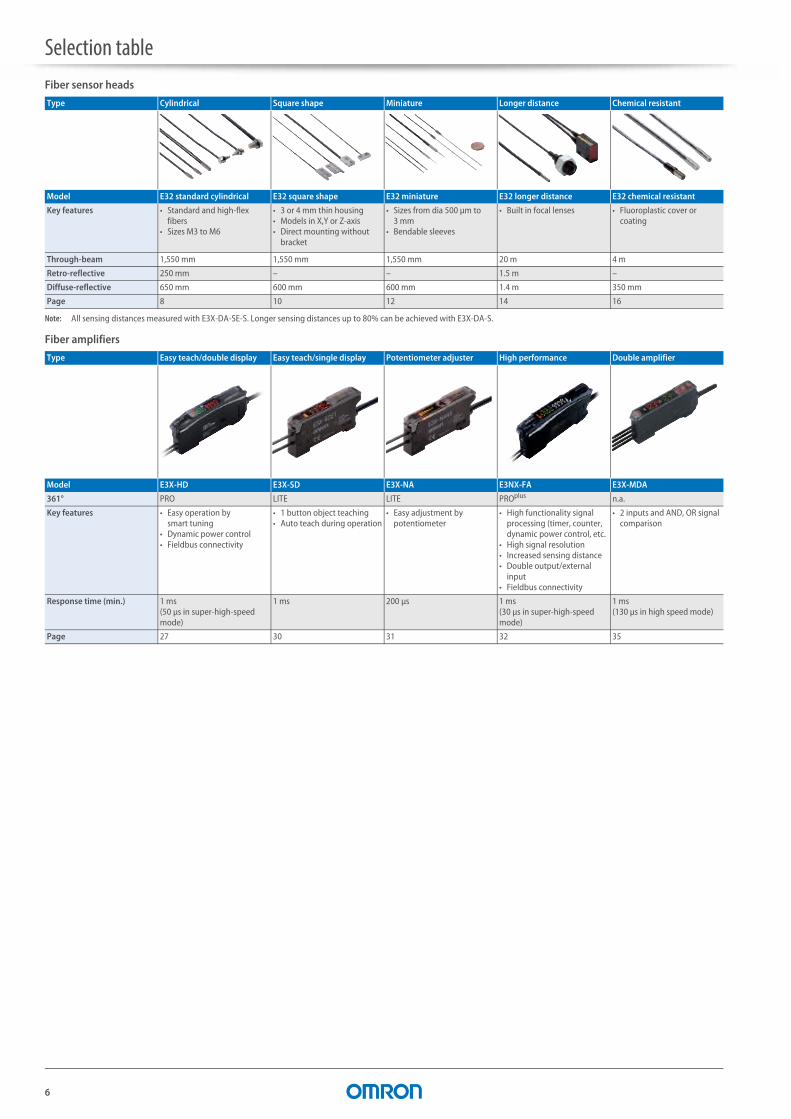
Selection tableFiber sensor heads
Note: All sensing distances measured with E3X-DA-SE-S. Longer sensing distances up to 80% can be achieved with E3X-DA-S.
Fiber amplifiers
Type Cylindrical Square shape Miniature Longer distance Chemical resistant
Model E32 standard cylindrical E32 square shape E32 miniature E32 longer distance E32 chemical resistant
Key features • Standard and high-flex fibers
• Sizes M3 to M6
• 3 or 4 mm thin housing• Models in X,Y or Z-axis• Direct mounting without
bracket
• Sizes from dia 500 μm to 3 mm
• Bendable sleeves
• Built in focal lenses • Fluoroplastic cover or coating
Through-beam 1,550 mm 1,550 mm 1,550 mm 20 m 4 m
Retro-reflective 250 mm – – 1.5 m –
Diffuse-reflective 650 mm 600 mm 600 mm 1.4 m 350 mm
Page 8 10 12 14 16
Type Easy teach/double display Easy teach/single display Potentiometer adjuster High performance Double amplifier
Model E3X-HD E3X-SD E3X-NA E3NX-FA E3X-MDA
361° PRO LITE LITE PROplus n.a.
Key features • Easy operation by smart tuning
• Dynamic power control• Fieldbus connectivity
• 1 button object teaching• Auto teach during operation
• Easy adjustment by potentiometer
• High functionality signal processing (timer, counter, dynamic power control, etc.
• High signal resolution• Increased sensing distance• Double output/external
input• Fieldbus connectivity
• 2 inputs and AND, OR signal comparison
Response time (min.) 1 ms (50 μs in super-high-speed mode)
1 ms 200 μs 1 ms (30 μs in super-high-speed mode)
1 ms(130 μs in high speed mode)
Page 27 30 31 32 35
7
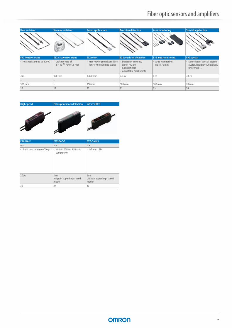
Fiber optic sensors and amplifiers
Heat resistant Vacuum resistant Robot applications Precision detection Area monitoring Special application
E32 heat resistant E32 vacuum resistant E32 robot E32 precision detection E32 area monitoring E32 special
• Heat resistant up to 400°C • Leakage rate of 1 × 10⁻¹⁰ Pa*m3/s max
• Free moving multicore fibers for >1 Mio bending cycles
• Detection accuracyup to 100 μm
• Coaxial fibers• Adjustable focal points
• Area monitoringup to 70 mm
• Detection of special objects (wafer, liquid level, flat glass, print mark ...)
3 m 950 mm 1,350 mm 3.8 m 4 m 3.8 m
– – – – – –
500 mm – 350 mm 600 mm 300 mm 20 mm
17 19 20 21 23 24
High speed Color/print mark detection Infrared LED
E3X-NA-F E3X-DAC-S E3X-DAH-S
n.a. n.a. n.a.
• Short turn on time of 20 μs • White LED and RGB ratio comparison
• Infrared LED
20 μs 1 ms (60 μs in super high speed mode)
1ms(55 μs in super high speed mode)
36 37 39
8
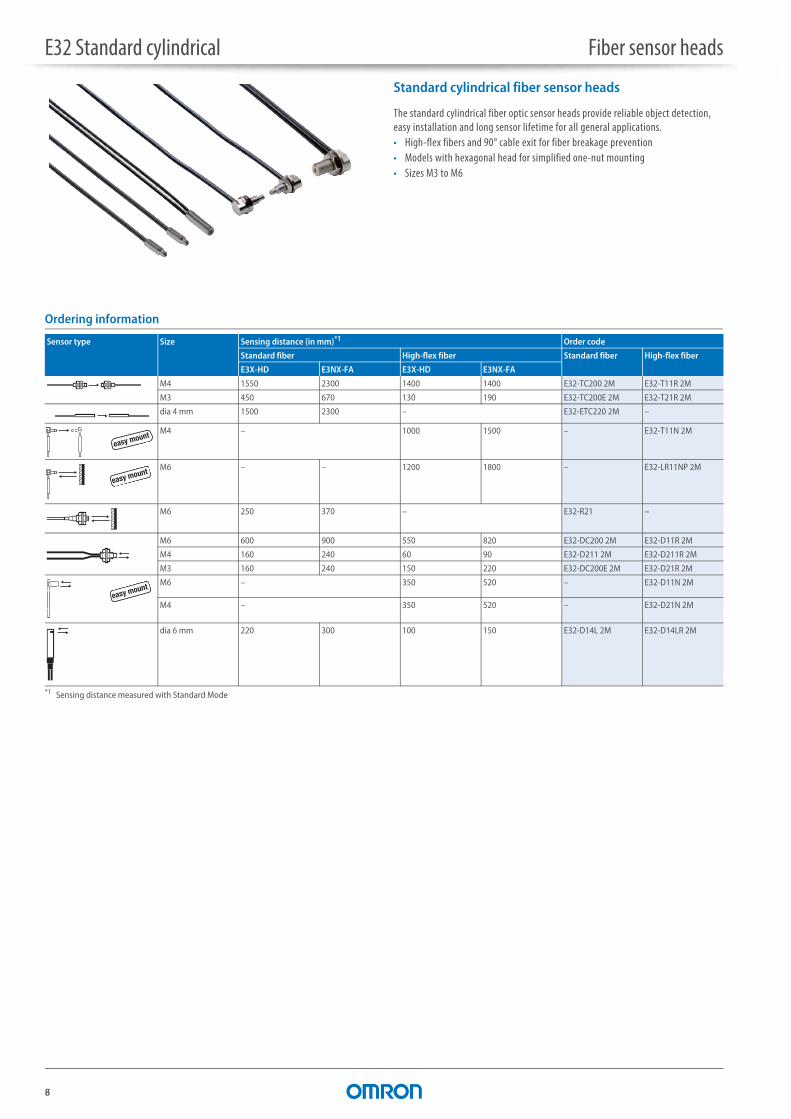
E32 Standard cylindrical Fiber sensor heads
Standard cylindrical fiber sensor heads
The standard cylindrical fiber optic sensor heads provide reliable object detection, easy installation and long sensor lifetime for all general applications.• High-flex fibers and 90° cable exit for fiber breakage prevention• Models with hexagonal head for simplified one-nut mounting• Sizes M3 to M6
Ordering information
Sensor type Size Sensing distance (in mm)*1
*1 Sensing distance measured with Standard Mode
Order code
Standard fiber High-flex fiber Standard fiber High-flex fiber
E3X-HD E3NX-FA E3X-HD E3NX-FA
M4 1550 2300 1400 1400 E32-TC200 2M E32-T11R 2M
M3 450 670 130 190 E32-TC200E 2M E32-T21R 2M
dia 4 mm 1500 2300 – E32-ETC220 2M –
M4 – 1000 1500 – E32-T11N 2M
M6 – – 1200 1800 – E32-LR11NP 2M
M6 250 370 – E32-R21 –
M6 600 900 550 820 E32-DC200 2M E32-D11R 2M
M4 160 240 60 90 E32-D211 2M E32-D211R 2M
M3 160 240 150 220 E32-DC200E 2M E32-D21R 2M
M6 – 350 520 – E32-D11N 2M
M4 – 350 520 – E32-D21N 2M
dia 6 mm 220 300 100 150 E32-D14L 2M E32-D14LR 2M
easy mount
easy mount
easy mount

E32 Standard cylindrical Fiber sensor heads
9
1Fi
ber –
gen
eralSpecifications
Item Standard High Flex
E32-_C200E32-_C220
E32-D14L E32-_C200E E32-D211 E32-R21 E32-_RE32-T11NE32-D11N
E32-D14LRE32-D211R
E32-D21N E32-LR11NP
Permissible bending radius R25 R10 R1 R2
Cut to length Yes
Ambient temperature –40°C to 70°C
Material Head Brass-nickel plated
Stainless steel Brass-nickel plated
Stainless steel Plastic (ABS) Brass-nickel plated
Stainless steel Brass-nickel plated
Fiber PMMA
Sheath Polyethylene coating PVC coating
Degree of protection IEC 60529 IP67 IP50
Models with hexagonal back for simple one-nut mounting
Cable exit shifted by 90° for preventing fiber breakage
Hi-flex multicore fibers for flexibility in installation without fiber breakage
10
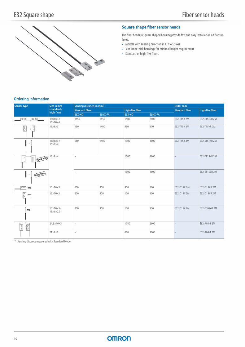
E32 Square shape Fiber sensor heads
Square shape fiber sensor heads
The fiber heads in square shaped housing provide fast and easy installation on flat sur-faces.• Models with sensing direction in X, Y or Z axis• 3 or 4mm thick housings for minimal height requirement• Standard or high-flex fibers
Ordering information
Sensor type Size in mm(standard / high-flex)
Sensing distance (in mm)*1
*1 Sensing distance measured with Standard Mode
Order code
Standard fiber High-flex fiber Standard fiber High-flex fiber
E3X-HD E3NX-FA E3X-HD E3NX-FA
15×8×3 / 15×10×4
1550 1550 1400 2100 E32-T15X 2M E32-ETS10R 2M
15×8×3 950 1400 450 670 E32-T15Y 2M E32-T15YR 2M
15×8×3 / 15×9×4
950 1400 1300 1800 E32-T15Z 2M E32-ETS14R 2M
13×9×4 – 1300 1800 – E32-ET15YR 2M
– 1300 1800 – E32-ET15ZR 2M
15×10×3 600 900 350 520 E32-D15X 2M E32-D15XR 2M
15×10×3 200 300 100 150 E32-D15Y 2M E32-D15YR 2M
15×10×3 / 13×6×2.3
200 300 100 150 E32-D15Z 2M E32-EDS24R 2M
24.5×10×3 – 1780 2600 – E32-A03-1 2M
21×9×2 – 680 1000 – E32-A04-1 2M
Long hole
Long hole

E32 Square shape Fiber sensor heads
11
1Fi
ber –
gen
eralSpecifications
Item Standard High flex
E32-_15 E32-A03_ E32-A04_ E32-E E32-_15_R
Permissible bending radius R25 R10 R1
Cut to length Yes
Ambient temperature –40°C to 70°C
Material Head Aluminium Brass-nickel plated Stainless steel Aluminium
Fiber PMMA
Sheath Polyethylene coating PVC coating
Degree of protection IEC 60529 IP67 IEC 60529 IP50 IEC 60529 IP67
Precise positioning during manufacturing for 90° optics to achieve minimal tolerance variations in optical output axis angle
90°
Space saving and fast mounting without additional brackets

12
E32 Miniature Fiber sensor heads
Miniature fiber sensor heads
The miniature fiber heads provide high accuracy in smallest spaces and reliable detection of minute objects.• Sizes from dia 500 μm to 3 mm• Side view models with precision axis alignment for highest accuracy• Bendable sleeves for precision positioning
Ordering information
Sensor type Size Sensing distance (in mm)*1
*1 Sensing distance measured in Standard Mode
Order code
Standard fiber High-flex fiber Standard fiber High-flex fiber
E3X-HD E3NX-FA E3X-HD E3NX-FA
dia 3 mm 1550 2300 1000 1500 E32-T12 2M E32-T12R 2M
dia 2 mm 450 670 250 370 E32-T22 2M E32-T22R 2M
dia 1.5 mm 450 670 450 670 E32-T222 2M E32-T222R 2M
dia 1 mm – 250 370 – E32-T223R 2M
dia 3 mm 950 1420 450 670 E32-T14L 2M E32-T14LR 2M
dia 2 mm 680 1020 – E32-A04 2M –
dia 1 mm 250 370 100 150 E32-T24 E32-T24R 2M
dia 1.2 mm 1550 2300 1000 1500 E32-TC200B*2
*2 Models with 40 mm sleeve instead of 90 mm sleeve are available by adding ’4’ to the order code at the end, e.g. E32-TC200B4
E32-TC200BR*2
dia 0.9 mm 450 670 250 370 E32-TC200F*2 E32-TC200FR*2
dia 3 mm 160 240 60 90 E32-D22 2M E32-D22R 2M
dia 2 mm 150 220 80 120 E32-D32 2M E32-D32R 2M
dia 1.5 mm – 60 90 – E32-D22B 2M
dia 2 mm 60 90 30 40 E32-D24 E32-D24R 2M
dia 2.5 mm 600 900 350 520 E32-DC200B 2M*2 *3
*3 Sleeve cannot be bent
E32-DC200BR *2 *3
dia 1.2 mm 160 240 60 90 E32-DC200F*2 E32-DC200FR*2
dia 0.8 mm – – 30 40 – E32-D33 2M
dia 0.5 mm – – 6 9 – E32-D331 2M
Bendable sleeve
Bendable sleeve
E32 Miniature Fiber sensor heads
13
1Fi
ber –
gen
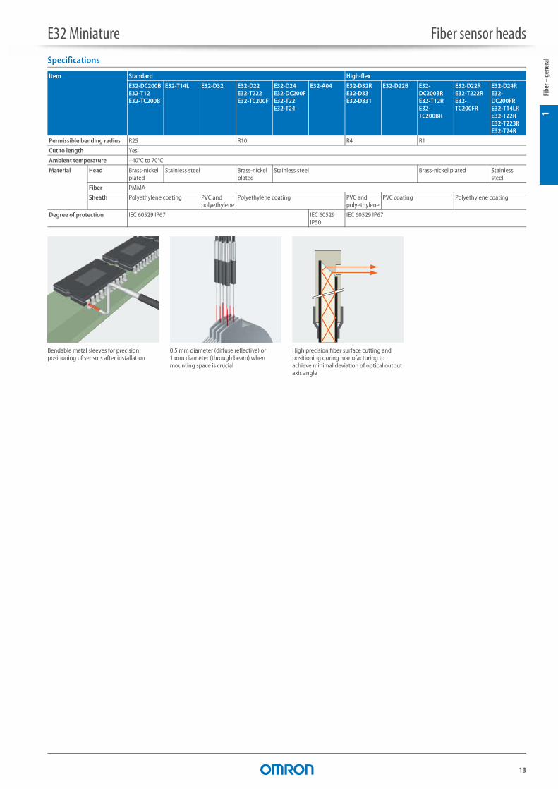
eralSpecifications
Item Standard High-flex
E32-DC200BE32-T12E32-TC200B
E32-T14L E32-D32 E32-D22E32-T222E32-TC200F
E32-D24E32-DC200FE32-T22E32-T24
E32-A04 E32-D32RE32-D33E32-D331
E32-D22B E32-DC200BRE32-T12RE32-TC200BR
E32-D22RE32-T222RE32-TC200FR
E32-D24RE32-DC200FRE32-T14LRE32-T22RE32-T223RE32-T24R
Permissible bending radius R25 R10 R4 R1
Cut to length Yes
Ambient temperature –40°C to 70°C
Material Head Brass-nickel plated
Stainless steel Brass-nickel plated
Stainless steel Brass-nickel plated Stainless steel
Fiber PMMA
Sheath Polyethylene coating PVC and polyethylene
Polyethylene coating PVC and polyethylene
PVC coating Polyethylene coating
Degree of protection IEC 60529 IP67 IEC 60529 IP50
IEC 60529 IP67
Bendable metal sleeves for precision positioning of sensors after installation
0.5 mm diameter (diffuse reflective) or 1 mm diameter (through beam) when mounting space is crucial
High precision fiber surface cutting and positioning during manufacturing to achieve minimal deviation of optical output axis angle

14
E32 Longer distance Fiber sensor heads
Longer distance fiber sensor heads
With built-in focal lenses the longer distance fiber heads provide enhanced operational stability in dusty environments or long distance applications• Sensing distance up to 20 m• Built-in focal lens• Sizes from dia 2 mm to M14• Easy installation - no need to attach auxiliary lenses
Ordering information
Sensor type Size Sensing distance (in mm)*1
*1 Sensing distance measured in Standard Mode
Order code
Standard fiber High-flex fiber Standard fiber High-flex fiber
E3X-HD E3NX-FA E3X-HD E3NX-FA
M14 20000 20000 – – E32-T17L –
25.2 × 10.5 × 8 mm 4000 4000 – – E32-T14 –
M4 – 3500 4000 – E32-LT11N 2M
M4 4000 4000 3500 4000 E32-LT11 2M E32-LT11R 2M
M3 1350 2000 – – E32-TC200A 2M –
dia 3 mm 2600 3900 – – E32-T12L 2M –
dia 2 mm 850 1200 – – E32-T22L 2M –
21.5 × 27 × 10 mm 1500 2250 – – E32-R16 2M –
M6 – 350 520 – E32-LD11N 2M
22 × 17.5 × 9 mm 1400 2100 – – E32-D16 2M –
M6 360 540 350 520 E32-LD11 2M E32-LD11R 2M
M4 260 390 – – E32-D21L 2M –
dia 3 mm 450 670 – – E32-D12 2M –
easy mount
Reflector
easy mount
E32 Longer distance Fiber sensor heads
15
1Fi
ber –
gen
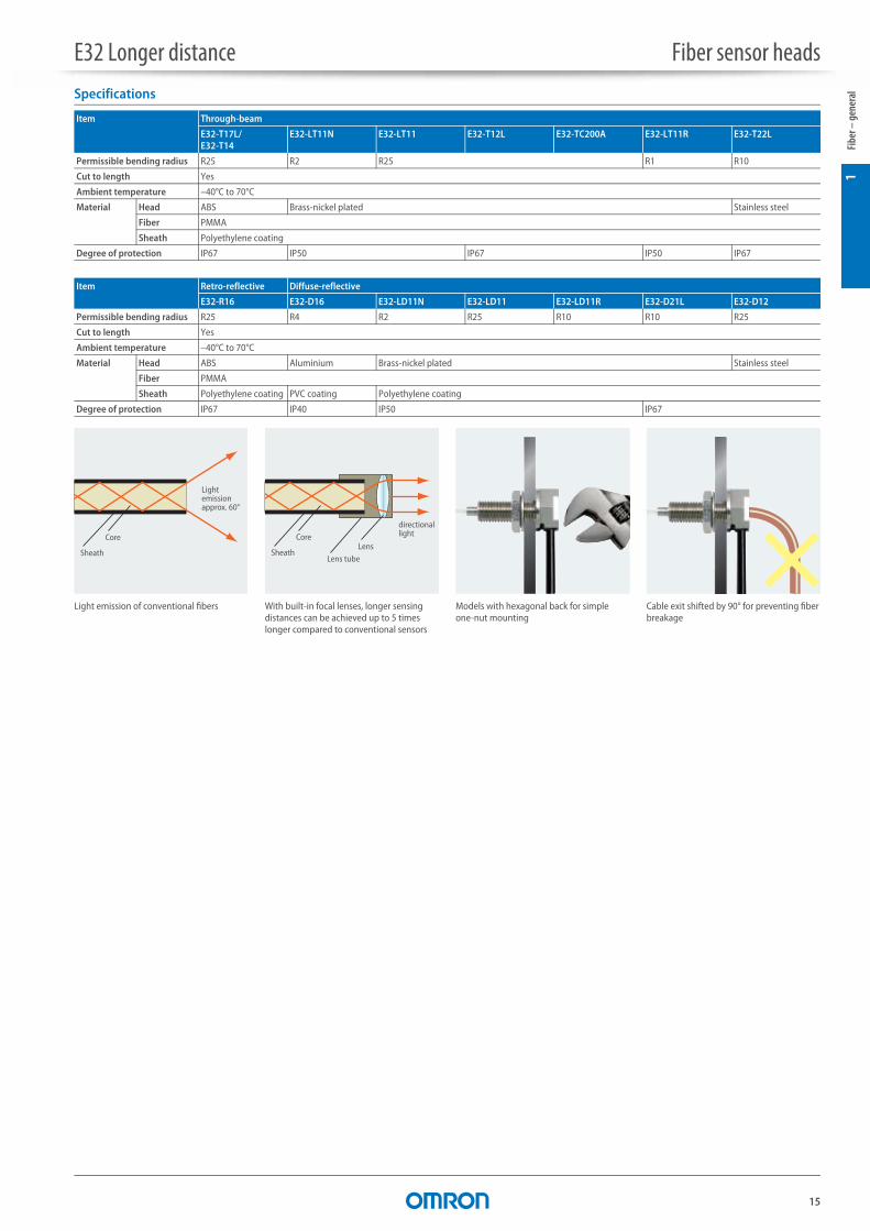
eralSpecifications
Item Through-beam
E32-T17L/E32-T14
E32-LT11N E32-LT11 E32-T12L E32-TC200A E32-LT11R E32-T22L
Permissible bending radius R25 R2 R25 R1 R10
Cut to length Yes
Ambient temperature –40°C to 70°C
Material Head ABS Brass-nickel plated Stainless steel
Fiber PMMA
Sheath Polyethylene coating
Degree of protection IP67 IP50 IP67 IP50 IP67
Item Retro-reflective Diffuse-reflective
E32-R16 E32-D16 E32-LD11N E32-LD11 E32-LD11R E32-D21L E32-D12
Permissible bending radius R25 R4 R2 R25 R10 R10 R25
Cut to length Yes
Ambient temperature –40°C to 70°C
Material Head ABS Aluminium Brass-nickel plated Stainless steel
Fiber PMMA
Sheath Polyethylene coating PVC coating Polyethylene coating
Degree of protection IP67 IP40 IP50 IP67
Light emission of conventional fibers
Sheath
Core
Light emissionapprox. 60°
With built-in focal lenses, longer sensing distances can be achieved up to 5 times longer compared to conventional sensors
Sheath
directional lightCore
Lens tube
Lens
Models with hexagonal back for simple one-nut mounting
Cable exit shifted by 90° for preventing fiber breakage
16
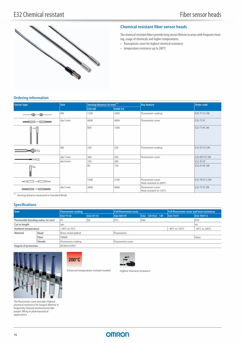
E32 Chemical resistant Fiber sensor heads
Chemical resistant fiber sensor heads
The chemical resistant fibers provide long sensor lifetime in areas with frequent clean-ing, usage of chemicals and higher temperatures.• fluoroplastic cover for highest chemical resistance• temperature resistance up to 200°C
Ordering information
Specifications
Sensor type Size Sensing distance (in mm)*1
*1 Sensing distance measured in Standard Mode
Key feature Order code
E3X-HD E3NX-FA
M4 1350 2000 Fluororesin coating E32-T11U 2M
dia 5 mm 4000 4000 Fluororesin cover E32-T12F
800 1200 E32-T14F 2M
M6 350 520 Fluororesin coating E32-D11U 2M
dia 7 mm 300 450 Fluororesin cover E32-ED11F 2M
dia 6 mm 190 280 E32-D12F
80 120 E32-D14F 2M
1400 2100 Fluororesin cover Heat resistant to 200°C
E32-T81F-S 2M
dia 5 mm 2800 4000 Fluororesin cover Heat resistant to 150°C
E32-T51F 2M
Item Fluororesin coating Full fluororesin cover Full fluororesin cover and heat resistance
E32-T11U E32-D11U E32-ED11F E32-_12F/E32-_14F E32-T51F E32-T81F-S
Permissible bending radius (in mm) R1 R4 R75 R40 R10
Cut to length yes no
Ambient temperature –40°C to 70°C –40°C to 150°C –40°C to 200°C
Material Head Brass-nickel plated Fluororesin
Fiber PMMA Glass
Sheath Fluororesin coating Fluororesin cover
Degree of protection IEC60529 IP67
200°C
Enhanced temperature resistant models
The fluororesin cover provides highest chemical resistance for longest lifetime in frequently cleaned environments like aseptic filling in pharmaceutical applications
Highest chemical resistance

17
2Fi
bers
– en
v. re
sista
nce
E32 Heat resistant Fiber sensor heads
Heat resistant fiber sensor heads
The wide range of heat resistant fibers provides long sensor lifetime with the highest protection in demanding environments• heat resistant up to 400°C• sizes from dia 2 mm to M6• models for long distances or high detection accuracy
Ordering information
Sensor type Size Sensing distance (in mm)*1
*1 Sensing distance measured in Standard Mode
Key feature Order code
E3X-HD E3NX-FA For E3NX-FA and E3X-HD amplifiers
For E3X-NA amplifier
M4 3000 4000 –40°C to 150°C E32-T51 2M
800 1200 –40°C to 100°C*2, high-flex
*2 Short term resistance. For continuous operation –40°C to 90°C
E32-T51R 2M
550 820 –40°C to 200°C E32-T81R-S 2M
900 1350 –60°C to 350°C E32-T61-S 2M
dia 2 mm 450 670 –40°C to 150°C E32-T54 2M
dia 3 mm 2600 3900 –40°C to 200°C E32-T84S-S 2M
M6 500 750 –40°C to 150°C E32-D51 2M
280 420 –40°C to 100°C*2, high-flex E32-D51R 2M
180 270 –40°C to 200°C E32-D81R-S 2M E32-D81R 2M
180 270 –60°C to 350°C E32-D61-S 2M E32-D61
M4 120 180 –40°C to 400°C E32-D73-S 2M E32-D73
23×20×9 mm 15–38 –40°C to 150°C E32-A09H 2M
30×24×9 mm 20–30 –40°C to 300°C E32-A09H2 2M
25×18×5 mm 1–5 –40°C to 300°C E32-L64 2M
36×18×5 mm 5–18 E32-L66 2M
E32 Heat resistant Fiber sensor heads
18
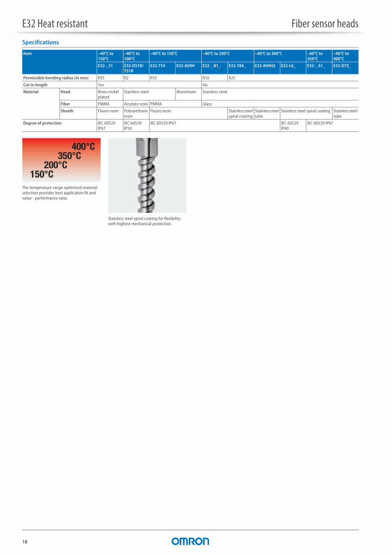
Specifications
Item –40°C to 150°C
–40°C to 100°C
–40°C to 150°C –40°C to 200°C –40°C to 300°C –60°C to 350°C
–40°C to 400°C
E32-_51 E32-D51R/T51R
E32-T54 E32-A09H E32-_ 81_ E32-T84_ E32-A09H2 E32-L6_ E32-_ 61_ E32-D73_
Permissible bending radius (in mm) R35 R2 R35 R10 R25
Cut to length Yes No
Material Head Brass-nickelplated
Stainless steel Aluminium Stainless steel
Fiber PMMA Acrylate resin PMMA Glass
Sheath Fluoro resin Polyurethane resin
Fluoro resin Stainless steel spiral coating
Stainless steel tube
Stainless steel spiral coating Stainless steel tube
Degree of protection IEC 60529 IP67
IEC 60529 IP50
IEC 60529 IP67 IEC 60529 IP40
IEC 60529 IP67
150°C200°C
350°C400°C
The temperature range optimised material selection provides best application fit and value - performance ratio.
Stainless steel spiral coating for flexibility with highest mechanical protection.
19
2Fi
bers
– en
v. re
sista
nce
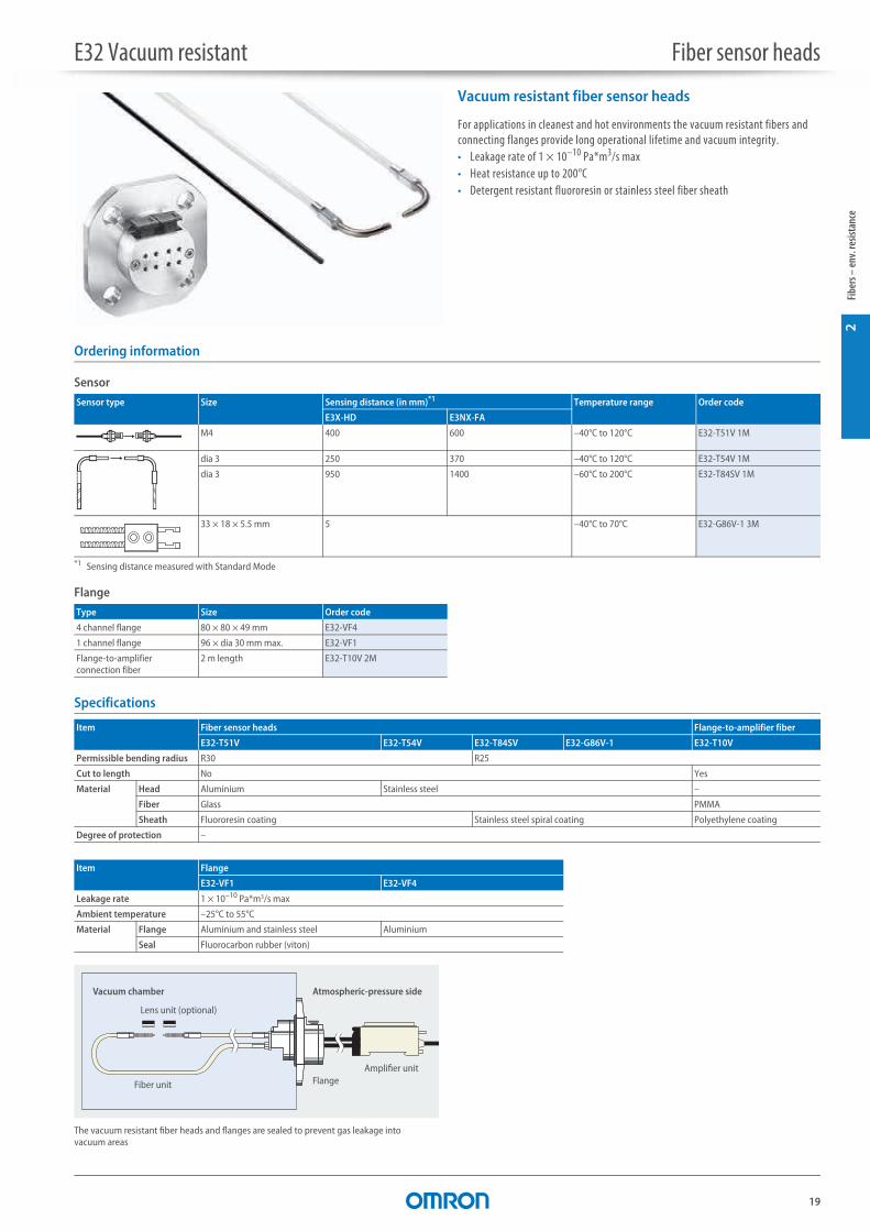
E32 Vacuum resistant Fiber sensor heads
Vacuum resistant fiber sensor heads
For applications in cleanest and hot environments the vacuum resistant fibers and connecting flanges provide long operational lifetime and vacuum integrity.• Leakage rate of 1 × 10⁻¹⁰ Pa*m3/s max• Heat resistance up to 200°C• Detergent resistant fluororesin or stainless steel fiber sheath
Ordering information
Sensor
Flange
Specifications
Sensor type Size Sensing distance (in mm)*1
*1 Sensing distance measured with Standard Mode
Temperature range Order code
E3X-HD E3NX-FA
M4 400 600 –40°C to 120°C E32-T51V 1M
dia 3 250 370 –40°C to 120°C E32-T54V 1M
dia 3 950 1400 –60°C to 200°C E32-T84SV 1M
33 × 18 × 5.5 mm 5 –40°C to 70°C E32-G86V-1 3M
Type Size Order code
4 channel flange 80 × 80 × 49 mm E32-VF4
1 channel flange 96 × dia 30 mm max. E32-VF1
Flange-to-amplifier connection fiber
2 m length E32-T10V 2M
Item Fiber sensor heads Flange-to-amplifier fiber
E32-T51V E32-T54V E32-T84SV E32-G86V-1 E32-T10V
Permissible bending radius R30 R25
Cut to length No Yes
Material Head Aluminium Stainless steel –
Fiber Glass PMMA
Sheath Fluororesin coating Stainless steel spiral coating Polyethylene coating
Degree of protection –
Item Flange
E32-VF1 E32-VF4
Leakage rate 1 × 10⁻¹⁰ Pa*m3/s max
Ambient temperature –25°C to 55°C
Material Flange Aluminium and stainless steel Aluminium
Seal Fluorocarbon rubber (viton)
The vacuum resistant fiber heads and flanges are sealed to prevent gas leakage into vacuum areas
Vacuum chamber
Lens unit (optional)
Atmospheric-pressure side
Amplifier unitFlangeFiber unit

20
E32 Robot application Fiber sensor heads
Robot application fiber sensor heads
For applications on frequently or fast moving parts, the robot fibers reduce the risk of fiber breakage with a guaranteed operational life of more than 1 million bending cycles• Free moving multicore fibers for > 1 mio bending cycles• Square shapes for easy surface installation• Cylindrical sizes from dia 1.5 mm to M6
Ordering information
Specifications
Sensor type Size Sensing distance (in mm)*1
*1 Sensing distance measured in Standard Mode
Order code
E3X-HD E3NX-FA
M4 1350 2000 E32-T11 2M
M3 400 600 E32-T21 2M
dia 3 mm 1350 2000 E32-T12B
dia 2 mm 400 600 E32-T221B
dia 1.5 mm 400 600 E32-T22B
15 × 18 × 3 mm 1350 2000 E32-T15XB 2M
M6 350 520 E32-D11 2M
M4 140 210 E32-D21B 2M
M3 60 90 E32-D21 2M
dia 1.5 mm 60 90 E32-D22B 2M
15 × 10 × 3 mm 350 520 E32-D15XB 2M
Item Square Cylindrical
E32-D15XBE32-T15XB
E32-T21 E32-D11E32-T11
E32-D21E32-T12BE32-T22B
E32-D21BE32-D22BE32-T221B
Permissible bending radius R4
Cut to length Yes
Ambient temperature –40°C to 70°C
Material Head Aluminium Brass-nickel plated Stainless steel
Fiber PMMA
Sheath PVC coating Polyethylene coating PVC coating
Degree of protection IEC 60529 IP67
Guaranteed more than 1 mio bending operations
Free moving fiber cores prevent fiber breakage and light intensity loss when the fiber is bent.
free moving cores re-arranged
core structure
21
3Fi
bers
– sp
ecia
l
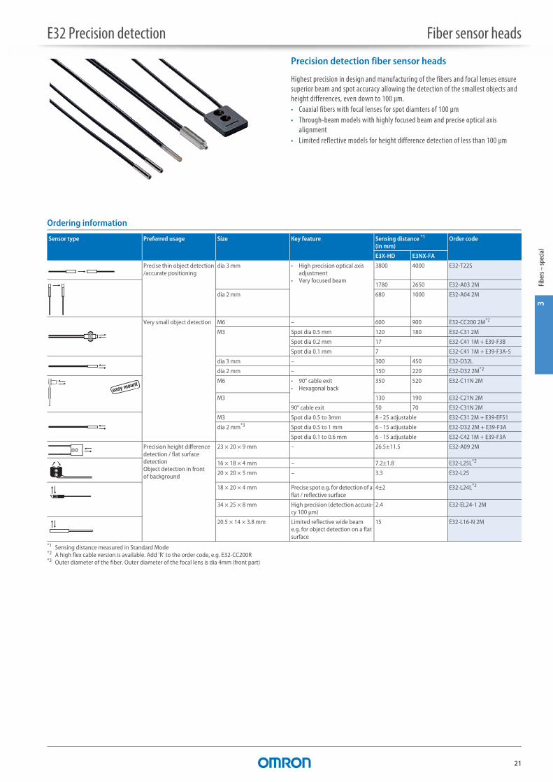
E32 Precision detection Fiber sensor heads
Precision detection fiber sensor heads
Highest precision in design and manufacturing of the fibers and focal lenses ensure superior beam and spot accuracy allowing the detection of the smallest objects and height differences, even down to 100 μm.• Coaxial fibers with focal lenses for spot diamters of 100 μm• Through-beam models with highly focused beam and precise optical axis
alignment• Limited reflective models for height difference detection of less than 100 μm
Ordering information
Sensor type Preferred usage Size Key feature Sensing distance *1
(in mm)
*1 Sensing distance measured in Standard Mode
Order code
E3X-HD E3NX-FA
Precise thin object detection /accurate positioning
dia 3 mm • High precision optical axisadjustment
• Very focused beam
3800 4000 E32-T22S
1780 2650 E32-A03 2M
dia 2 mm 680 1000 E32-A04 2M
Very small object detection M6 – 600 900 E32-CC200 2M*2
*2 A high flex cable version is available. Add ’R’ to the order code, e.g. E32-CC200R
M3 Spot dia 0.5 mm 120 180 E32-C31 2M
Spot dia 0.2 mm 17 E32-C41 1M + E39-F3B
Spot dia 0.1 mm 7 E32-C41 1M + E39-F3A-5
dia 3 mm – 300 450 E32-D32L
dia 2 mm – 150 220 E32-D32 2M*2
M6 • 90° cable exit • Hexagonal back
350 520 E32-C11N 2M
M3 130 190 E32-C21N 2M
90° cable exit 50 70 E32-C31N 2M
M3 Spot dia 0.5 to 3mm 8 - 25 adjustable E32-C31 2M + E39-EF51
dia 2 mm*3
*3 Outer diameter of the fiber. Outer diameter of the focal lens is dia 4mm (front part)
Spot dia 0.5 to 1 mm 6 - 15 adjustable E32-D32 2M + E39-F3A
Spot dia 0.1 to 0.6 mm 6 - 15 adjustable E32-C42 1M + E39-F3A
Precision height difference detection / flat surface detectionObject detection in front of background
23 × 20 × 9 mm – 26.5±11.5 E32-A09 2M
16 × 18 × 4 mm – 7.2±1.8 E32-L25L*2
20 × 20 × 5 mm – 3.3 E32-L25
18 × 20 × 4 mm Precise spot e.g. for detection of a flat / reflective surface
4±2 E32-L24L*2
34 × 25 × 8 mm High precision (detection accura-cy 100 μm)
2.4 E32-EL24-1 2M
20.5 × 14 × 3.8 mm Limited reflective wide beam e.g. for object detection on a flat surface
15 E32-L16-N 2M
easy mount
E32 Precision detection Fiber sensor heads
22
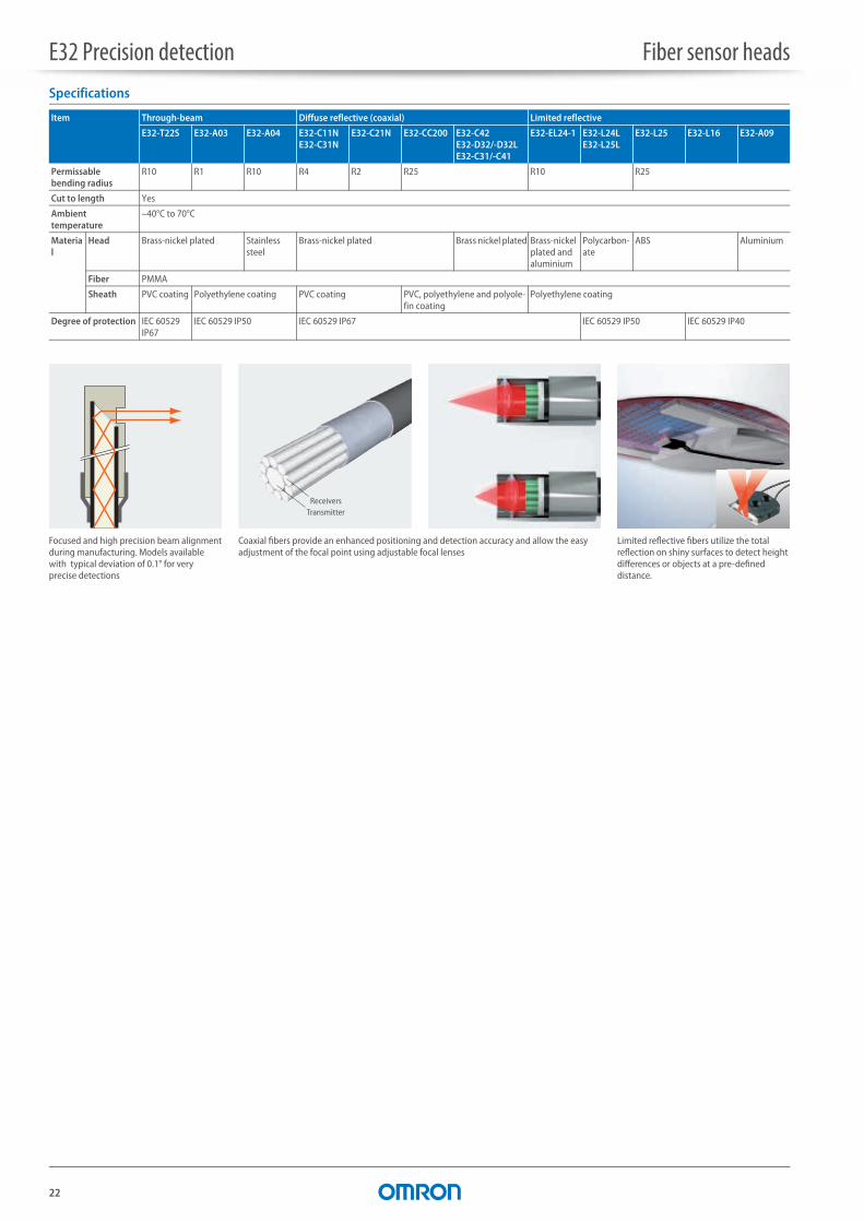
Specifications
Item Through-beam Diffuse reflective (coaxial) Limited reflective
E32-T22S E32-A03 E32-A04 E32-C11NE32-C31N
E32-C21N E32-CC200 E32-C42E32-D32/-D32LE32-C31/-C41
E32-EL24-1 E32-L24LE32-L25L
E32-L25 E32-L16 E32-A09
Permissable bending radius
R10 R1 R10 R4 R2 R25 R10 R25
Cut to length Yes
Ambient temperature
–40°C to 70°C
Material
Head Brass-nickel plated Stainless steel
Brass-nickel plated Brass nickel plated Brass-nickel plated and aluminium
Polycarbon-ate
ABS Aluminium
Fiber PMMA
Sheath PVC coating Polyethylene coating PVC coating PVC, polyethylene and polyole-fin coating
Polyethylene coating
Degree of protection IEC 60529 IP67
IEC 60529 IP50 IEC 60529 IP67 IEC 60529 IP50 IEC 60529 IP40
Coaxial fibers provide an enhanced positioning and detection accuracy and allow the easy adjustment of the focal point using adjustable focal lenses
ReceiversTransmitter
Focused and high precision beam alignment during manufacturing. Models available with typical deviation of 0.1° for very precise detections
Limited reflective fibers utilize the total reflection on shiny surfaces to detect height differences or objects at a pre-defined distance.
23
3Fi
bers
– sp
ecia
l
E32 Area monitoring Lightcurtains and area sensors
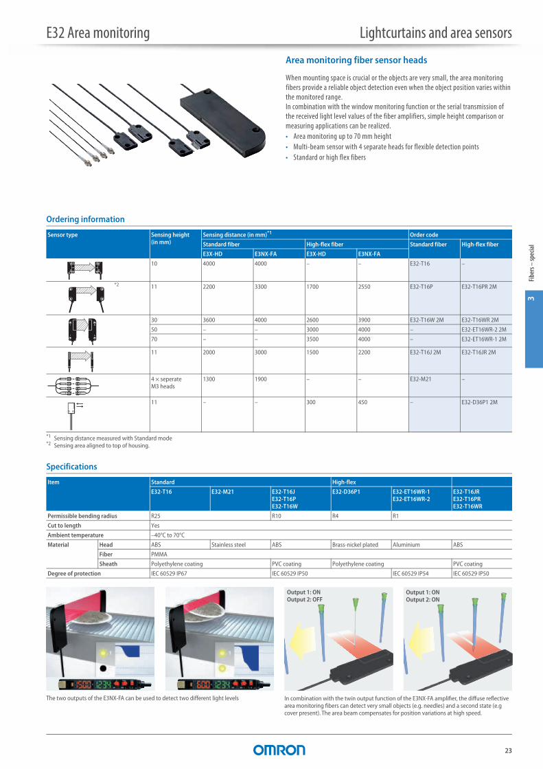
Area monitoring fiber sensor heads
When mounting space is crucial or the objects are very small, the area monitoring fibers provide a reliable object detection even when the object position varies within the monitored range.In combination with the window monitoring function or the serial transmission of the received light level values of the fiber amplifiers, simple height comparison or measuring applications can be realized.• Area monitoring up to 70 mm height• Multi-beam sensor with 4 separate heads for flexible detection points• Standard or high flex fibers
Ordering information
Specifications
Sensor type Sensing height (in mm)
Sensing distance (in mm)*1
*1 Sensing distance measured with Standard mode
Order code
Standard fiber High-flex fiber Standard fiber High-flex fiber
E3X-HD E3NX-FA E3X-HD E3NX-FA
10 4000 4000 – – E32-T16 –
*2
*2 Sensing area aligned to top of housing.
11 2200 3300 1700 2550 E32-T16P E32-T16PR 2M
30 3600 4000 2600 3900 E32-T16W 2M E32-T16WR 2M
50 – – 3000 4000 – E32-ET16WR-2 2M
70 – – 3500 4000 – E32-ET16WR-1 2M
11 2000 3000 1500 2200 E32-T16J 2M E32-T16JR 2M
4 × seperate M3 heads
1300 1900 – – E32-M21 –
11 – – 300 450 – E32-D36P1 2M
Item Standard High-flex
E32-T16 E32-M21 E32-T16JE32-T16PE32-T16W
E32-D36P1 E32-ET16WR-1E32-ET16WR-2
E32-T16JRE32-T16PRE32-T16WR
Permissible bending radius R25 R10 R4 R1
Cut to length Yes
Ambient temperature –40°C to 70°C
Material Head ABS Stainless steel ABS Brass-nickel plated Aluminium ABS
Fiber PMMA
Sheath Polyethylene coating PVC coating Polyethylene coating PVC coating
Degree of protection IEC 60529 IP67 IEC 60529 IP50 IEC 60529 IP54 IEC 60529 IP50
In combination with the twin output function of the E3NX-FA amplifier, the diffuse reflective area monitoring fibers can detect very small objects (e.g. needles) and a second state (e.g cover present). The area beam compensates for position variations at high speed.
Output 1: ONOutput 2: OFF
Output 1: ONOutput 2: ON
The two outputs of the E3NX-FA can be used to detect two different light levels
24
E32 Special application Fiber sensor heads
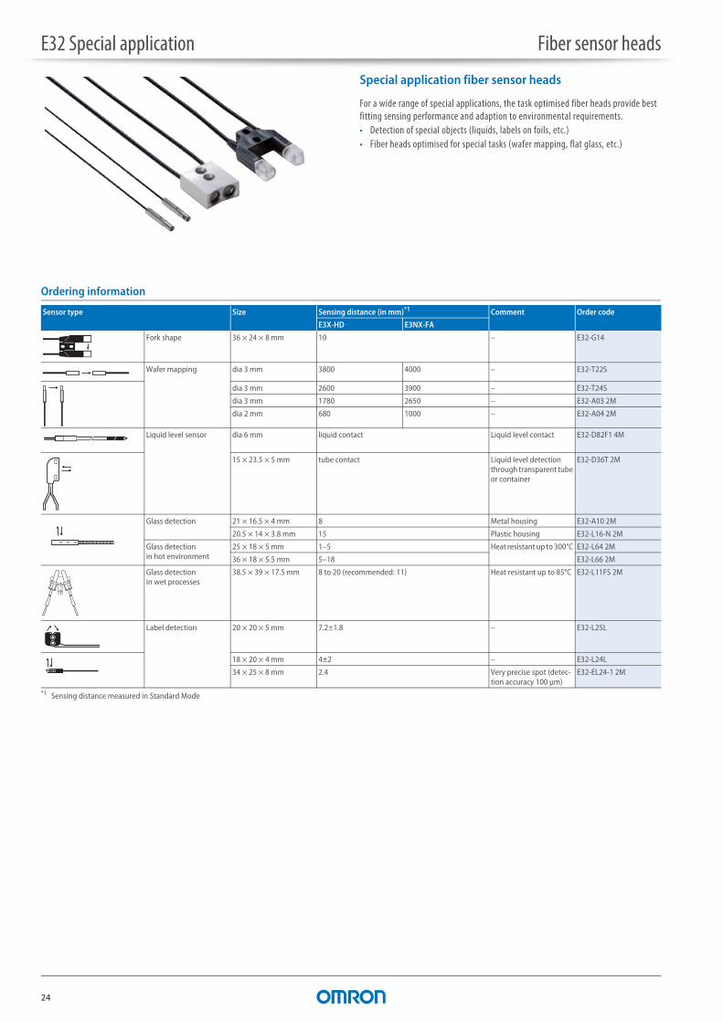
Special application fiber sensor heads
For a wide range of special applications, the task optimised fiber heads provide best fitting sensing performance and adaption to environmental requirements.• Detection of special objects (liquids, labels on foils, etc.)• Fiber heads optimised for special tasks (wafer mapping, flat glass, etc.)
Ordering information
Sensor type Size Sensing distance (in mm)*1
*1 Sensing distance measured in Standard Mode
Comment Order code
E3X-HD E3NX-FA
Fork shape 36 × 24 × 8 mm 10 – E32-G14
Wafer mapping dia 3 mm 3800 4000 – E32-T22S
dia 3 mm 2600 3900 – E32-T24S
dia 3 mm 1780 2650 – E32-A03 2M
dia 2 mm 680 1000 – E32-A04 2M
Liquid level sensor dia 6 mm liquid contact Liquid level contact E32-D82F1 4M
15 × 23.5 × 5 mm tube contact Liquid level detection through transparent tube or container
E32-D36T 2M
Glass detection 21 × 16.5 × 4 mm 8 Metal housing E32-A10 2M
20.5 × 14 × 3.8 mm 15 Plastic housing E32-L16-N 2M
Glass detection in hot environment
25 × 18 × 5 mm 1–5 Heat resistant up to 300°C E32-L64 2M
36 × 18 × 5.5 mm 5–18 E32-L66 2M
Glass detection in wet processes
38.5 × 39 × 17.5 mm 8 to 20 (recommended: 11) Heat resistant up to 85°C E32-L11FS 2M
Label detection 20 × 20 × 5 mm 7.2±1.8 – E32-L25L
18 × 20 × 4 mm 4±2 – E32-L24L
34 × 25 × 8 mm 2.4 Very precise spot (detec-tion accuracy 100 μm)
E32-EL24-1 2M
E32 Special application Fiber sensor heads
25
3Fi
bers
– sp
ecia
l
Specifications
Item E32-D82F1E32-L11FS
E32-G14 E32-A10 E32-L16-N E32-L66 E32-L64
Permissable bending radius R40 R25
Cut to length Yes No
Ambient temperature –40°C to 70°C –40°C to 300°C
Material Head PFA ABS ABS PVC Stainless steel
Fiber PMMA Glass
Sheath Polyethylene coating Stainless steel spiral coating
Degree of protection IEC 60529 IP67 IEC 60529 IP30 IEC 60529 IP40 IEC 60529 IP40 IEC 60529 IP50
Item E32-EL24-1 E32-T24S E32-L24LE32-L25L
E32-A04 E32-D36T E32-A03 E32-T22S
Permissable bending radius R10 R4 R1
Cut to length Yes
Ambient temperature –40°C to 70°C
Material Head Brass-nickel plated and alumini-um
Stainless steel Brass-nickel plated Stainless steel ABS Brass-nickel plated
Fiber PMMA
Sheath Polyethylene coating PVC coating Polyethylene coating PVC coating Polyethylene coating PVC coating
Degree of protection IEC 60529 IP67 IEC 60529 IP50 IEC 60529 IP67 IEC 60529 IP50 IEC 60529 IP67
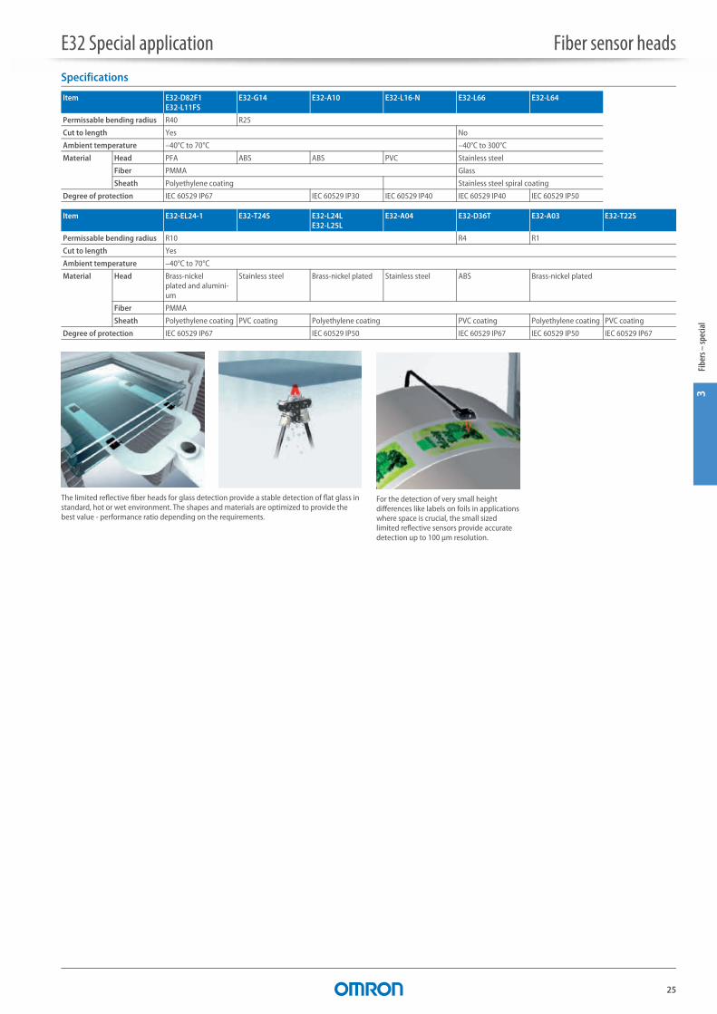
For the detection of very small height differences like labels on foils in applications where space is crucial, the small sized limited reflective sensors provide accurate detection up to 100 μm resolution.
The limited reflective fiber heads for glass detection provide a stable detection of flat glass in standard, hot or wet environment. The shapes and materials are optimized to provide the best value - performance ratio depending on the requirements.
26
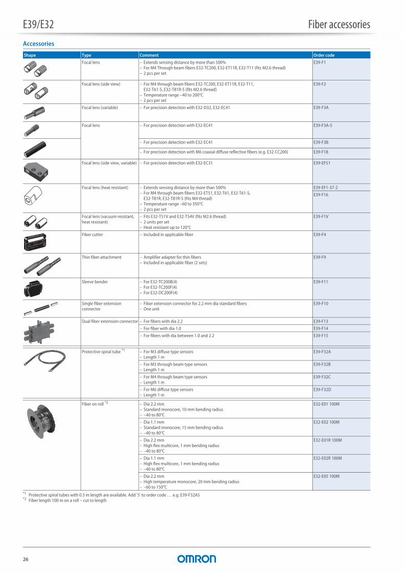
E39/E32 Fiber accessoriesAccessories
Shape Type Comment Order code
Focal lens – Extends sensing distance by more than 500%– For M4 Through beam fibers E32-TC200, E32-ET11R, E32-T11 (fits M2.6 thread)– 2 pcs per set
E39-F1
Focal lens (side view) – For M4 through beam fibers E32-TC200, E32-ET11R, E32-T11, E32-T61-S, E32-T81R-S (fits M2.6 thread)
– Temperature range –40 to 200°C– 2 pcs per set
E39-F2
Focal lens (variable) – For precision detection with E32-D32, E32-EC41 E39-F3A
Focal lens – For precision detection with E32-EC41 E39-F3A-5
– For precision detection with E32-EC41 E39-F3B
– For precision detection with M6 coaxial diffuse reflective fibers (e.g. E32-CC200) E39-F18
Focal lens (side view, variable) – For precision detection with E32-EC31 E39-EF51
Focal lens (heat resistant) – Extends sensing distance by more than 500%– For M4 through beam fibers E32-ET51, E32-T61, E32-T61-S,
E32-T81R, E32-T81R-S (fits M4 thread)– Temperature range –60 to 350°C– 2 pcs per set
E39-EF1-37-2
E39-F16
Focal lens (vacuum resistant, heat resistant)
– Fits E32-T51V and E32-T54V (fits M2.6 thread)– 2 units per set– Heat resistant up to 120°C
E39-F1V
Fiber cutter – Included in applicable fiber E39-F4
Thin fiber attachment – Amplifier adapter for thin fibers– Included in applicable fiber (2 sets)
E39-F9
Sleeve bender – For E32-TC200B(4)– For E32-TC200F(4)– For E32-DC200F(4)
E39-F11
Single fiber extension connector
– Fiber extension connector for 2.2 mm dia standard fibers– One unit
E39-F10
Dual fiber extension connector – For fibers with dia 2.2 E39-F13
– For fiber with dia 1.0 E39-F14
– For fibers with dia between 1.0 and 2.2 E39-F15
Protective spiral tube *1
*1 Protective spiral tubes with 0.5 m length are available. Add '5' to order code … e.g. E39-F32A5
– For M3 diffuse type sensors– Length 1 m
E39-F32A
– For M3 through beam type sensors– Length 1 m
E39-F32B
– For M4 through beam type sensors– Length 1 m
E39-F32C
– For M6 diffuse type sensors– Length 1 m
E39-F32D
Fiber on roll *2
*2 Fiber length 100 m on a roll – cut to length
– Dia 2.2 mm– Standard monocore, 10 mm bending radius– –40 to 80°C
E32-E01 100M
– Dia 1.1 mm– Standard monocore, 15 mm bending radius– –40 to 80°C
E32-E02 100M
– Dia 2.2 mm– High flex multicore, 1 mm bending radius– –40 to 80°C
E32-E01R 100M
– Dia 1.1 mm– High flex multicore, 1 mm bending radius– –40 to 80°C
E32-E02R 100M
– Dia 2.2 mm– High temperature monocore, 20 mm bending radius– –60 to 150°C
E32-E05 100M
27
5Am
plifi
ers –
easy
usa
ge
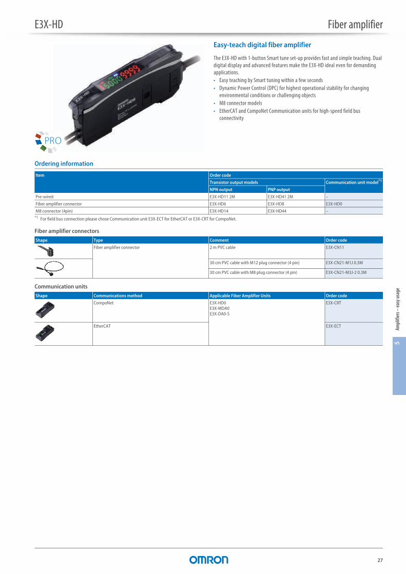
E3X-HD Fiber amplifier
Easy-teach digital fiber amplifier
The E3X-HD with 1-button Smart tune set-up provides fast and simple teaching. Dual digital display and advanced features make the E3X-HD ideal even for demanding applications.• Easy teaching by Smart tuning within a few seconds• Dynamic Power Control (DPC) for highest operational stability for changing
environmental conditions or challenging objects• M8 connector models• EtherCAT and CompoNet Communication units for high-speed field bus
connectivity
Ordering information
Fiber amplifier connectors
Communication units
Item Order code
Transistor output models Communication unit model*1
*1 For field bus connection please chose Communication unit E3X-ECT for EtherCAT or E3X-CRT for CompoNet.
NPN output PNP output
Pre-wired E3X-HD11 2M E3X-HD41 2M –
Fiber amplifier connector E3X-HD6 E3X-HD8 E3X-HD0
M8 connector (4pin) E3X-HD14 E3X-HD44 –
Shape Type Comment Order code
Fiber amplifier connector 2 m PVC cable E3X-CN11
30 cm PVC cable with M12 plug connector (4 pin) E3X-CN21-M1J 0.3M
30 cm PVC cable with M8 plug connector (4 pin) E3X-CN21-M3J-2 0.3M
Shape Communications method Applicable Fiber Amplifier Units Order code
CompoNet E3X-HD0E3X-MDA0E3X-DA0-S
E3X-CRT
EtherCAT E3X-ECT
E3X-HD Fiber amplifier
28
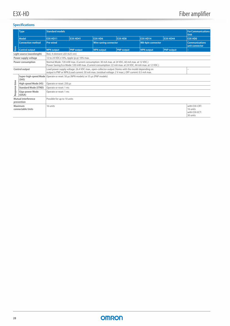
Specifications
Item
Type Standard models For Communications Unit
Model E3X-HD11 E3X-HD41 E3X-HD6 E3X-HD8 E3X-HD14 E3X-HD44 E3X-HD0
Connection method Pre-wired Wire-saving connector M8-4pin connector Communications unit connector
Control output NPN output PNP output NPN output PNP output NPN output PNP output –
Light source (wavelength) Red, 4-element LED (625 nm)
Power supply voltage 12 to 24 VDC±10%, ripple (p-p) 10% max.
Power consumption Normal Mode: 720 mW max. (Current consumption: 30 mA max. at 24 VDC, 60 mA max. at 12 VDC.)Power Saving Eco Mode: 530 mW max. (Current consumption: 22 mA max. at 24 VDC, 44 mA max. at 12 VDC.)
Control output Load power supply voltage: 26.4 VDC max., open-collector output (Varies with the model depending on output is PNP or NPN.)Load current: 50 mA max. (residual voltage: 2 V max.), OFF current: 0.5 mA max.
–
Resp
onse
tim
e
Super-high-speed Mode (SHS)
Operate or reset: 50 μs (NPN models) or 55 μs (PNP models)
High-speed Mode (HS) Operate or reset: 250 μs
Standard Mode (STND) Operate or reset: 1 ms
Giga-power Mode (GIGA)
Operate or reset: 1 ms
Mutual interference prevention
Possible for up to 10 units
Maximum connectable Units
16 units with E3X-CRT: 16 unitswith E3X-ECT: 30 units
E3X-HD Fiber amplifier
29
5Am
plifi
ers –
easy
usa
ge
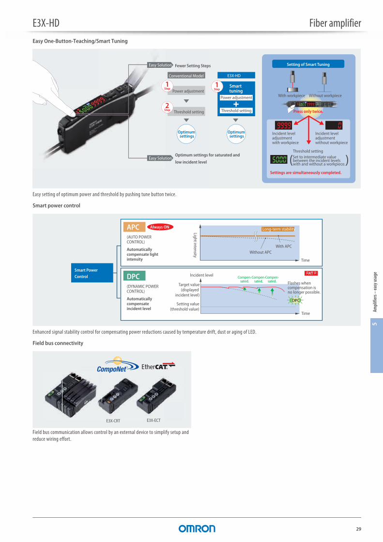
Easy One-Button-Teaching/Smart Tuning
Easy setting of optimum power and threshold by pushing tune button twice.
Smart power control
Enhanced signal stability control for compensating power reductions caused by temperature drift, dust or aging of LED.
Field bus connectivity
Field bus communication allows control by an external device to simplify setup and reduce wiring effort.
Easy Solution
1Power adjustment
Threshold setting
Conventional Model E3X-HD
Smart tuning
Power adjustment
Threshold setting
Optimum settings
Optimum settings
Step1
2
Step
Step
Fewer Setting Steps
Easy SolutionOptimum settings for saturated and
low incident level
Incident level adjustment with workpiece
Incident level adjustment without workpiece
Threshold setting
Press only twice.
Settings are simultaneously completed.
Setting of Smart Tuning
Set to intermediate value between the incident levels with and without a workpiece.
With workpiece Without workpiece
( )
Without APCWith APC
Light intensity
Time
Long-term stability
Flashes when compensation is no longer possible.
Incident level
Target value(displayed
incident level)
Compen-sated.
Compen-sated.
Compen-sated.
Setting value(threshold value)
Time
APC(AUTO POWER CONTROL)
Automatically compensate light intensity
DPC(DYNAMIC POWER CONTROL)
Automatically compensate incident level
Smart Power
Control
Always ON
DPC
E3X-ECTE3X-CRT
30
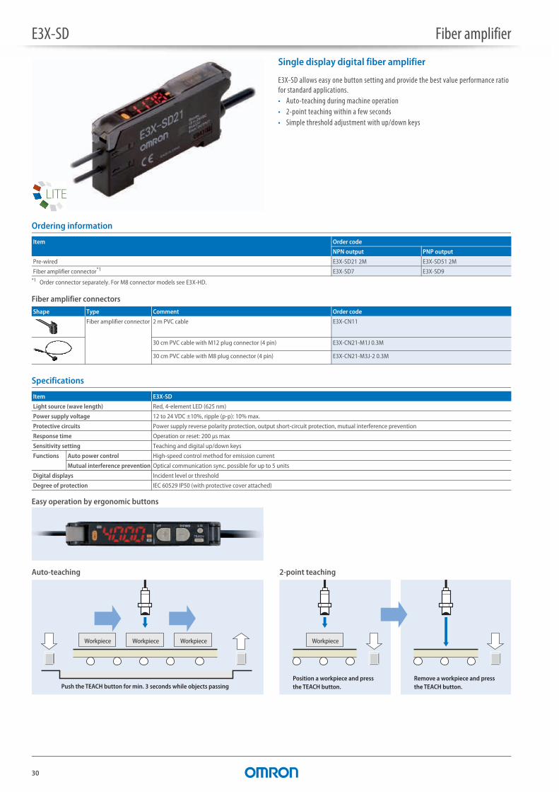
E3X-SD Fiber amplifier
Single display digital fiber amplifier
E3X-SD allows easy one button setting and provide the best value performance ratio for standard applications.• Auto-teaching during machine operation• 2-point teaching within a few seconds• Simple threshold adjustment with up/down keys
Ordering information
Fiber amplifier connectors
Specifications
Easy operation by ergonomic buttons
Auto-teaching 2-point teaching
Item Order code
NPN output PNP output
Pre-wired E3X-SD21 2M E3X-SD51 2M
Fiber amplifier connector*1
*1 Order connector separately. For M8 connector models see E3X-HD.
E3X-SD7 E3X-SD9
Shape Type Comment Order code
Fiber amplifier connector 2 m PVC cable E3X-CN11
30 cm PVC cable with M12 plug connector (4 pin) E3X-CN21-M1J 0.3M
30 cm PVC cable with M8 plug connector (4 pin) E3X-CN21-M3J-2 0.3M
Item E3X-SD
Light source (wave length) Red, 4-element LED (625 nm)
Power supply voltage 12 to 24 VDC ±10%, ripple (p-p): 10% max.
Protective circuits Power supply reverse polarity protection, output short-circuit protection, mutual interference prevention
Response time Operation or reset: 200 μs max
Sensitivity setting Teaching and digital up/down keys
Functions Auto power control High-speed control method for emission current
Mutual interference prevention Optical communication sync. possible for up to 5 units
Digital displays Incident level or threshold
Degree of protection IEC 60529 IP50 (with protective cover attached)
Push the TEACH button for min. 3 seconds while objects passing
Workpiece Workpiece Workpiece
Remove a workpiece and press the TEACH button.
Position a workpiece and press the TEACH button.
Workpiece
31
5Am
plifi
ers –
easy
usa
ge
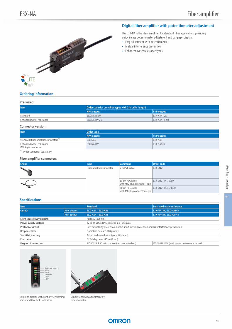
E3X-NA Fiber amplifier
Digital fiber amplifier with potentiometer adjustment
The E3X-NA is the ideal amplifier for standard fiber applications providing quick & easy potentiometer adjustment and bargraph display.• Easy adjustment with potentiometer• Mutual interference prevention• Enhanced water resistance types
Ordering information
Pre-wired
Connector version
Fiber amplifier connectors
Specifications
Item Order code (for pre-wired types with 2 m cable length)
NPN output PNP output
Standard E3X-NA11 2M E3X-NA41 2M
Enhanced water resistance E3X-NA11V 2M E3X-NA41V 2M
Item Order code
NPN output PNP output
Standard (fiber amplifier connector)*1
*1 Order connector separately.
E3X-NA6 E3X-NA8
Enhanced water resistance (M8 4-pin connector)
E3X-NA14V E3X-NA44V
Shape Type Comment Order code
Fiber amplifier connector 2 m PVC cable E3X-CN21
30 cm PVC cable with M12 plug connector (4 pin)
E3X-CN21-M1J 0.3M
30 cm PVC cable with M8 plug connector (4 pin)
E3X-CN21-M3J-2 0.3M
Item Standard Enhanced water resistance
Output NPN output E3X-NA11, E3X-NA6 E3X-NA11V, E3X-NA14V
PNP output E3X-NA41, E3X-NA8 E3X-NA41V, E3X-NA44V
Light source (wave length) Red LED (625 nm)
Power supply voltage 12 to 24 VDC±10%, ripple (p-p): 10% max.
Protective circuit Reverse polarity protection, output short-circuit protection, mutual interference prevention
Response time Operation or reset: 200 μs max.
Sensitivity setting 8-turn endless adjuster (potentiometer)
Functions OFF-delay timer: 40 ms (fixed)
Degree of protection IEC 60529 IP50 (with protective cover attached) IEC 60529 IP66 (with protective cover attached)
Switching status+20%+10%Threshold–10%–20%
Bargraph display with light level, switching status and threshold indicators
Simple sensitivity adjustment by potentiometer
32
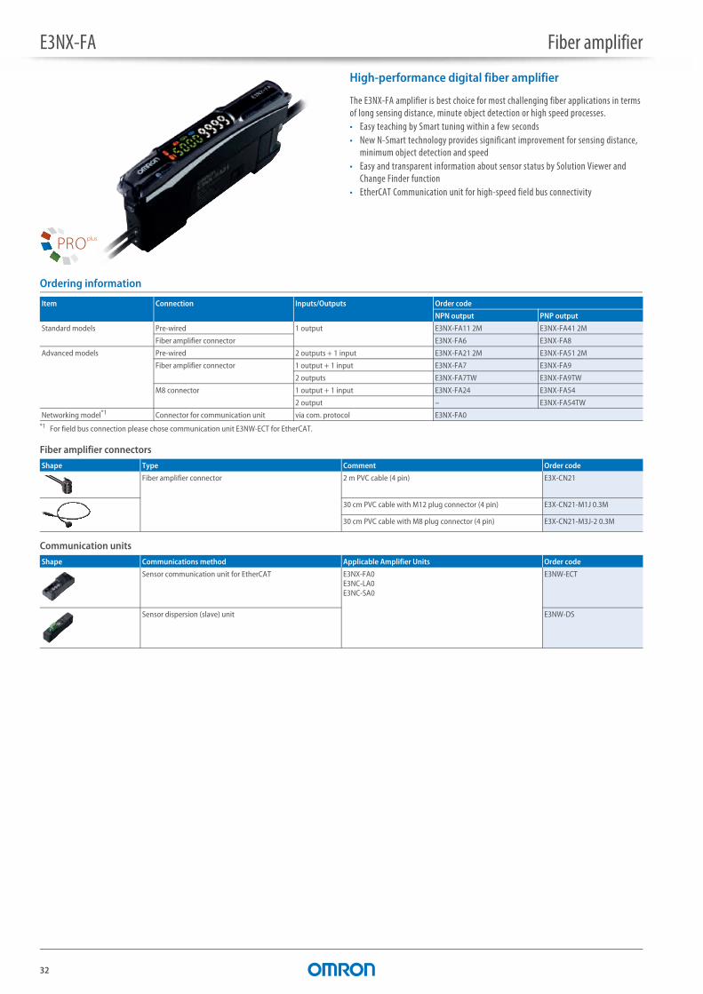
E3NX-FA Fiber amplifier
High-performance digital fiber amplifier
The E3NX-FA amplifier is best choice for most challenging fiber applications in terms of long sensing distance, minute object detection or high speed processes.• Easy teaching by Smart tuning within a few seconds• New N-Smart technology provides significant improvement for sensing distance,
minimum object detection and speed• Easy and transparent information about sensor status by Solution Viewer and
Change Finder function• EtherCAT Communication unit for high-speed field bus connectivity
Ordering information
Fiber amplifier connectors
Communication units
Item Connection Inputs/Outputs Order code
NPN output PNP output
Standard models Pre-wired 1 output E3NX-FA11 2M E3NX-FA41 2M
Fiber amplifier connector E3NX-FA6 E3NX-FA8
Advanced models Pre-wired 2 outputs + 1 input E3NX-FA21 2M E3NX-FA51 2M
Fiber amplifier connector 1 output + 1 input E3NX-FA7 E3NX-FA9
2 outputs E3NX-FA7TW E3NX-FA9TW
M8 connector 1 output + 1 input E3NX-FA24 E3NX-FA54
2 output – E3NX-FA54TW
Networking model*1
*1 For field bus connection please chose communication unit E3NW-ECT for EtherCAT.
Connector for communication unit via com. protocol E3NX-FA0
Shape Type Comment Order code
Fiber amplifier connector 2 m PVC cable (4 pin) E3X-CN21
30 cm PVC cable with M12 plug connector (4 pin) E3X-CN21-M1J 0.3M
30 cm PVC cable with M8 plug connector (4 pin) E3X-CN21-M3J-2 0.3M
Shape Communications method Applicable Amplifier Units Order code
Sensor communication unit for EtherCAT E3NX-FA0E3NC-LA0E3NC-SA0
E3NW-ECT
Sensor dispersion (slave) unit E3NW-DS
E3NX-FA Fiber amplifier
33
6Am
plifi
ers –
adva
nced
SpecificationsIt
em
Type Standard models Advanced models Model for sensor communications unit
NPN output E3NX-FA11 E3NX-FA6 E3NX-FA21 E3NX-FA7 E3NX-FA7TW E3NX-FA24 – E3NX-FA0
PNP output E3NX-FA41 E3NX-FA8 E3NX-FA51 E3NX-FA9 E3NX-FA9TW E3NX-FA54 E3NX-FA54TW
Connection method Pre-wired Wire-saving connector
Pre-wired Wire-saving connector M8 connector Connector for sensor communications unit
Inpu
ts/
outp
uts Outputs 1 output 2 outputs 1 output 2 outputs 1 output 2 outputs via com. protocol
External inputs – 1 input 1 input – 1 input – –
Light source (wavelength) Red, 4-element LED (625 nm)
Power supply voltage 10 to 30 VDC, including 10% ripple (p-p)
Power consumption At power supply voltage of 24 VDCStandard model or model for sensor communications unit:Normal mode: 960 mW max. (current consumption: 40 mA max.),Power saving eco mode: 840 mW max. (current consumption: 35 mA max.)Advanced model:Normal mode: 1,080 mW max. (current consumption: 45 mA max.),Power saving eco mode: 930 mW max. (current consumption: 40 mA max.)
Control output Load power supply voltage: 30 VDC max., open-collector outputLoad current: groups of 1 to 3 amplifires: 100 mA max., groups of 4 to 30 amplifires: 20 mA max.Residual voltage: at load current of less than 10 mA: 1 V max.
at load current of 10 to 100 mA: 2 V max.OFF current: 0.1 mA max.
–
Resp
onse
tim
e
Super-high-speed Mode (SHS)*1
*1 The mutual interference prevention function is disabled if the detection mode is set to super-high-speed mode.
Operate or reset for model with 1 output: 30 μs, with 2 outputs: 32 μs
High-speed Mode (HS) Operate or reset: 250 μs
Standard Mode (Stnd) Operate or reset: 1 ms
Giga-power Mode (GIGA)
Operate or reset: 16 ms
No.
of u
nits
for m
utua
lin
terf
eren
ce p
reve
ntio
n Super-high-speed Mode (SHS)*1
0
High-speed Mode (HS) 10
Standard Mode (Stnd) 10
Giga-power Mode (GIGA)
10
Functions Auto power control (APC), dynamic power control (DPC), timer, zero reset, resetting settings, eco mode, bank switching, power tuning, and hysteresis width
Maximum connectable units 30

E3NX-FA Fiber amplifier
34
Easy One-Button-Teaching/Smart Tuning
Easy setting of optimum power and threshold by pushing tune button twice.
Smart power control
Enhanced signal stability control for compensating power reductions caused by temperature drift, dust or aging of LED. Alarm output added for predictive maintenance.
N-Smart platform
The N-Smart platform provides wide portfolio of advanced sensors – all with the same intuitive operation concept and field bus connectivity.
5000 9999
Automatic setting of optimum values
ST
Dynamic rangeincreased by afactor of 40,000
Press the button once with a workpiece and once without a workpiece
TUNE
Set to the intermediate
value between
the incident levels with and
without a workpiece.
Incident level
adjustment with and
without a workpiece
Threshold + Incident level
Without APCWith APC
Light intensity
Time
Long-term stability
Flashes when compensation is no longer possible.
Incident level
Target value(displayed
incident level)
Compen-sated.
Compen-sated.
Compen-sated.
Setting value(threshold value)
Time
APC(AUTO POWER CONTROL)
Automatically compensate light intensity
DPC(DYNAMIC POWER CONTROL)
Automatically compensate incident level
Smart Power
Control
Always ON
DPC
35
6Am
plifi
ers –
adva
nced
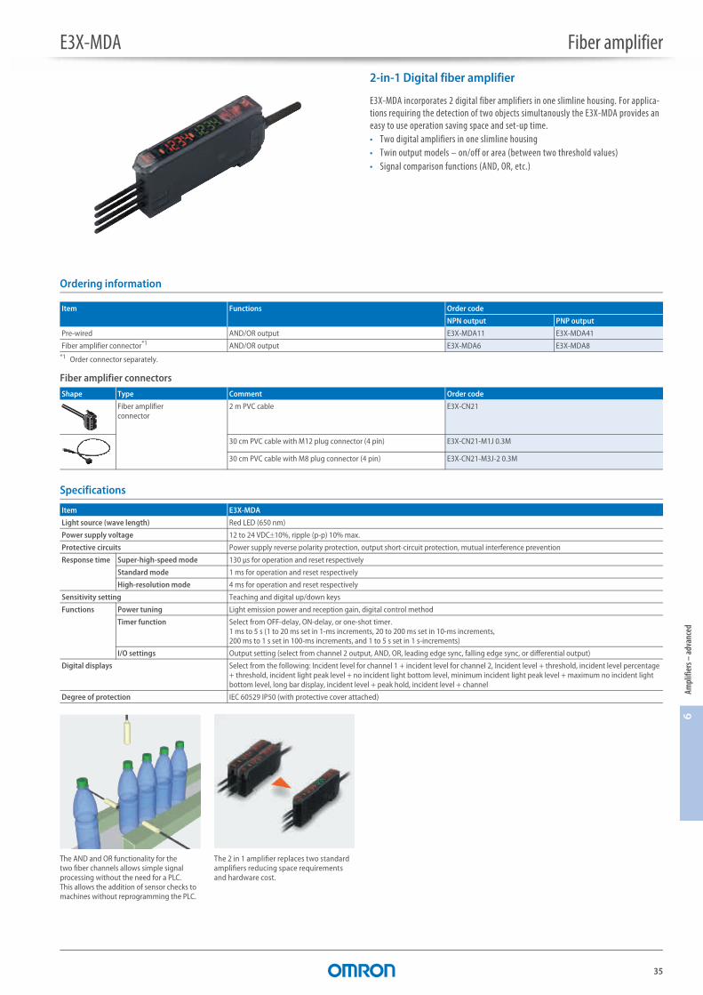
E3X-MDA Fiber amplifier
2-in-1 Digital fiber amplifier
E3X-MDA incorporates 2 digital fiber amplifiers in one slimline housing. For applica-tions requiring the detection of two objects simultanously the E3X-MDA provides an easy to use operation saving space and set-up time.• Two digital amplifiers in one slimline housing• Twin output models – on/off or area (between two threshold values)• Signal comparison functions (AND, OR, etc.)
Ordering information
Fiber amplifier connectors
Specifications
Item Functions Order code
NPN output PNP output
Pre-wired AND/OR output E3X-MDA11 E3X-MDA41
Fiber amplifier connector*1
*1 Order connector separately.
AND/OR output E3X-MDA6 E3X-MDA8
Shape Type Comment Order code
Fiber amplifier connector
2 m PVC cable E3X-CN21
30 cm PVC cable with M12 plug connector (4 pin) E3X-CN21-M1J 0.3M
30 cm PVC cable with M8 plug connector (4 pin) E3X-CN21-M3J-2 0.3M
Item E3X-MDA
Light source (wave length) Red LED (650 nm)
Power supply voltage 12 to 24 VDC10%, ripple (p-p) 10% max.
Protective circuits Power supply reverse polarity protection, output short-circuit protection, mutual interference prevention
Response time Super-high-speed mode 130 μs for operation and reset respectively
Standard mode 1 ms for operation and reset respectively
High-resolution mode 4 ms for operation and reset respectively
Sensitivity setting Teaching and digital up/down keys
Functions Power tuning Light emission power and reception gain, digital control method
Timer function Select from OFF-delay, ON-delay, or one-shot timer.1 ms to 5 s (1 to 20 ms set in 1-ms increments, 20 to 200 ms set in 10-ms increments, 200 ms to 1 s set in 100-ms increments, and 1 to 5 s set in 1 s-increments)
I/O settings Output setting (select from channel 2 output, AND, OR, leading edge sync, falling edge sync, or differential output)
Digital displays Select from the following: Incident level for channel 1 + incident level for channel 2, Incident level + threshold, incident level percentage + threshold, incident light peak level + no incident light bottom level, minimum incident light peak level + maximum no incident light bottom level, long bar display, incident level + peak hold, incident level + channel
Degree of protection IEC 60529 IP50 (with protective cover attached)
The AND and OR functionality for the two fiber channels allows simple signal processing without the need for a PLC. This allows the addition of sensor checks to machines without reprogramming the PLC.
The 2 in 1 amplifier replaces two standard amplifiers reducing space requirements and hardware cost.
36
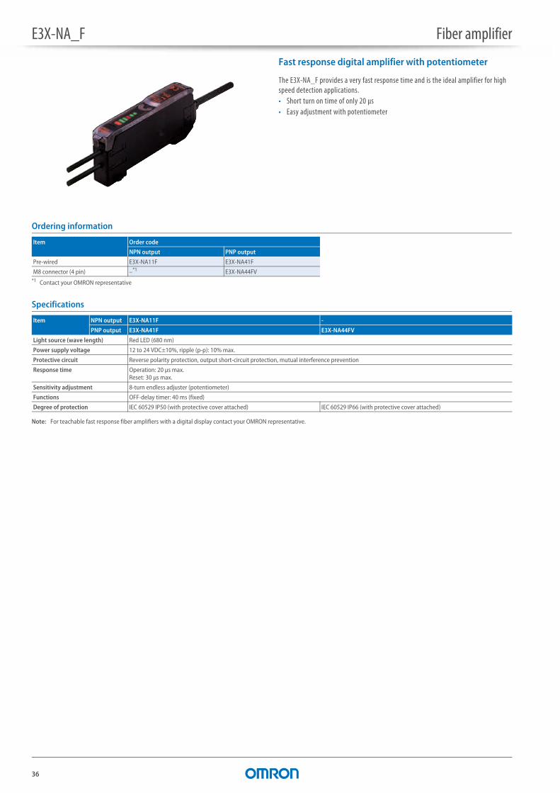
E3X-NA_F Fiber amplifier
Fast response digital amplifier with potentiometer
The E3X-NA_F provides a very fast response time and is the ideal amplifier for high speed detection applications.• Short turn on time of only 20 μs• Easy adjustment with potentiometer
Ordering information
Specifications
Note: For teachable fast response fiber amplifiers with a digital display contact your OMRON representative.
Item Order code
NPN output PNP output
Pre-wired E3X-NA11F E3X-NA41F
M8 connector (4 pin) –*1
*1 Contact your OMRON representative
E3X-NA44FV
Item NPN output E3X-NA11F -
PNP output E3X-NA41F E3X-NA44FV
Light source (wave length) Red LED (680 nm)
Power supply voltage 12 to 24 VDC±10%, ripple (p-p): 10% max.
Protective circuit Reverse polarity protection, output short-circuit protection, mutual interference prevention
Response time Operation: 20 μs max.Reset: 30 μs max.
Sensitivity adjustment 8-turn endless adjuster (potentiometer)
Functions OFF-delay timer: 40 ms (fixed)
Degree of protection IEC 60529 IP50 (with protective cover attached) IEC 60529 IP66 (with protective cover attached)
37
6Am
plifi
ers –
adva
nced
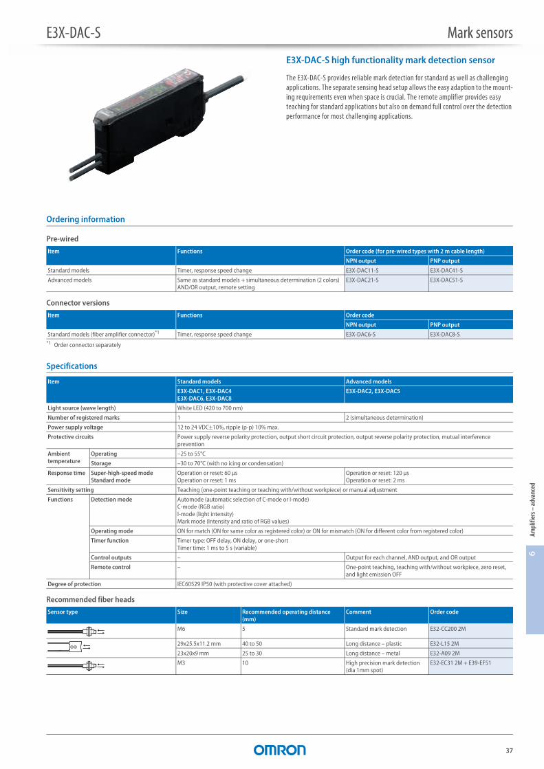
E3X-DAC-S Mark sensors
E3X-DAC-S high functionality mark detection sensor
The E3X-DAC-S provides reliable mark detection for standard as well as challenging applications. The separate sensing head setup allows the easy adaption to the mount-ing requirements even when space is crucial. The remote amplifier provides easy teaching for standard applications but also on demand full control over the detection performance for most challenging applications.
Ordering information
Pre-wired
Connector versions
Specifications
Recommended fiber heads
Item Functions Order code (for pre-wired types with 2 m cable length)
NPN output PNP output
Standard models Timer, response speed change E3X-DAC11-S E3X-DAC41-S
Advanced models Same as standard models + simultaneous determination (2 colors)AND/OR output, remote setting
E3X-DAC21-S E3X-DAC51-S
Item Functions Order code
NPN output PNP output
Standard models (fiber amplifier connector)*1
*1 Order connector separately
Timer, response speed change E3X-DAC6-S E3X-DAC8-S
Item Standard models Advanced models
E3X-DAC1, E3X-DAC4E3X-DAC6, E3X-DAC8
E3X-DAC2, E3X-DAC5
Light source (wave length) White LED (420 to 700 nm)
Number of registered marks 1 2 (simultaneous determination)
Power supply voltage 12 to 24 VDC±10%, ripple (p-p) 10% max.
Protective circuits Power supply reverse polarity protection, output short circuit protection, output reverse polarity protection, mutual interference prevention
Ambient temperature
Operating –25 to 55°C
Storage –30 to 70°C (with no icing or condensation)
Response time Super-high-speed modeStandard mode
Operation or reset: 60 μsOperation or reset: 1 ms
Operation or reset: 120 μsOperation or reset: 2 ms
Sensitivity setting Teaching (one-point teaching or teaching with/without workpiece) or manual adjustment
Functions Detection mode Automode (automatic selection of C-mode or I-mode)C-mode (RGB ratio)I-mode (light intensity)Mark mode (Intensity and ratio of RGB values)
Operating mode ON for match (ON for same color as registered color) or ON for mismatch (ON for different color from registered color)
Timer function Timer type: OFF delay, ON delay, or one-shortTimer time: 1 ms to 5 s (variable)
Control outputs – Output for each channel, AND output, and OR output
Remote control – One-point teaching, teaching with/without workpiece, zero reset, and light emission OFF
Degree of protection IEC60529 IP50 (with protective cover attached)
Sensor type Size Recommended operating distance (mm)
Comment Order code
M6 5 Standard mark detection E32-CC200 2M
29x25.5x11.2 mm 40 to 50 Long distance – plastic E32-L15 2M
23x20x9 mm 25 to 30 Long distance – metal E32-A09 2M
M3 10 High precision mark detection (dia 1mm spot)
E32-EC31 2M + E39-EF51
E3X-DAC-S Mark sensors
38
Fiber amplifier connectors
39,994
Shape Type Comment Order code
Fiber amplifier connector
2 m PVC cable E3X-CN21
30 cm PVC cable with M12 plug connector (4 pin) E3X-CN21-M1J 0.3M
30 cm PVC cable with M8 plug connector (4 pin) E3X-CN21-M3J-2 0.3M
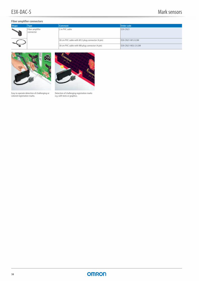
Easy to operate detection of challenging or colored registration marks.
Detection of challenging registration marks e.g. with texts or graphics.

39
6Am
plifi
ers –
adva
nced
E3X-DAH-S Fiber amplifier
Digital fiber amplifier with infrared LED
The digital fiber amplifiers with infrared LED are ideal for water detection applications or where visible light is not desired.• Infrared LED• LED power control and signal processing function
Ordering information
Pre-wired
Connector version
Fiber amplifier connectors
Specifications
Amplifier units with cables
Item Order code (for pre-wired types with 2 m cable length)
NPN output PNP output
Infrared light E3X-DAH11-S 2M E3X-DAH41-S 2M
Item Order code
NPN output PNP output
Infrared light (fiber amplifier connector)*1
*1 Order connector separately
E3X-DAH6-S E3X-DAH8-S
Shape Type Comment Order code
Fiber amplifier connector
2 m PVC cable E3X-CN21
30 cm PVC cable with M12 plug connector (4 pin) E3X-CN21-M1J 0.3M
30 cm PVC cable with M8 plug connector (4 pin) E3X-CN21-M3J-2 0.3M
Item NPN output E3X-DAH11-S, E3X-DAH6-S
PNP output E3X-DAH41-S, E3X-DAH8-S
Light source (wave length) Infrared LED
Power supply voltage 12 to 24 VDC10%, ripple (p-p) 10% max.
Protective circuits Power supply reverse polarity protection, output short circuit protection, mutual interference prevention
Responce time
Super-high-speed mode
NPN 48 μs for operation and 50 μs for reset
PNP 53 μs for operation and 55 μs for reset
Standard mode 1 ms for operation and reset respectively
High-resolution mode 4 ms for operation and reset respectively
Sensitivity setting Teaching and digital up/down keys
Functions Power tuning Light emission power and reception gain, digital control method
Timer function Select from OFF-delay, ON-delay, or one-shot timer. 1 ms to 5 s (1 to 20 ms set in 1-ms increments, 20 to 200 ms set in 10-ms increments, 200 ms to 1 s set in 100-ms increments, and 1 to 5 s set in 1 s-increments)
Digital displays Incident level + threshold or user specific
Degree of protection IEC 60529 IP50 (with protective cover attached)

40
Fiber optics Technical informationFiber optics
Item
Principle of operation Fiber optic photoelectric sensors comprise two parts, the amplifier and the sensing head. The amplifier contains the emitter (the light source) and receiver (detector) along with their associated electronics. The fiber optic cable is the means used to transfer the light to the sensing head.
The light source (an LED) transmits the light beam down the fiber optic cable by repeatedly reflecting the light off the boundary between the fiber core and its sheath. When it reaches the end of the fiber the light is dispersed at the end.
When the light is dispersed it spreads out and forms a beam much like that of other sensors, but on a smaller scale. With smaller light sources and lens areas the sensing ranges are on the whole much shorter.
Types of fiber Fiber optic heads mainly split into two types, through-beam and diffuse (although there are a few retro-reflective types). The principle of operation of both types is exactly that of standard photoelectric sensors.
Construction Standard fiber: Most fiber optic sensing heads use this configuration of fiber (i.e. a single fiber covered by a protective sheath). The fibers are usually plastic, 0.5 to 1 mm in diameter and covered in a plastic protective sheath.
Coaxial fiber: This gives greater accuracy. The core is used as the transmitter and the surrounding fibers are bundled together to form the receiver. This gives better accuracy, the target can enter the detecting area from any direction.
Multicore: These consist of large numbers of small fibers. This results in a more flexible cable (E32-R types) which can literally be tied in a knot.Robotic: In robotic fibers the multicore fibers are manufactured without fixa-tion. This allows them to move freely reducing mechanical stress when the fiber is bent.
LED
approx. 60°
Light
Sheath
Core
Matchstick
Fiber
Sheath
Receivers
Transmitter
Fibers
Sheath
Fiber optics Technical information
41
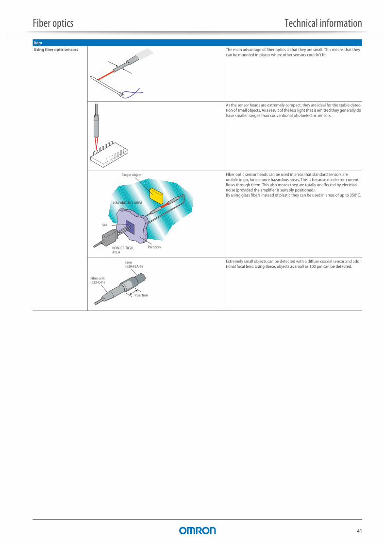
Using fiber optic sensors The main advantage of fiber optics is that they are small. This means that they can be mounted in places where other sensors couldn't fit.
As the sensor heads are extremely compact, they are ideal for the stable detec-tion of small objects. As a result of the less light that is emitted they generally do have smaller ranges than conventional photoelectric sensors.
Fiber optic sensor heads can be used in areas that standard sensors are unable to go, for instance hazardous areas, This is because no electric current flows through them. This also means they are totally unaffected by electrical noise (provided the amplifier is suitably positioned). By using glass fibers instead of plastic they can be used in areas of up to 350°C.
Extremely small objects can be detected with a diffuse coaxial sensor and addi-tional focal lens. Using these, objects as small as 100 μm can be detected.
Item
Partition
Target object
Seal
NON-CRITICAL AREA
HAZARDOUS AREA
Lens (E39-F3A-5)
Fiber unit(E32-C41)
Insertion
42
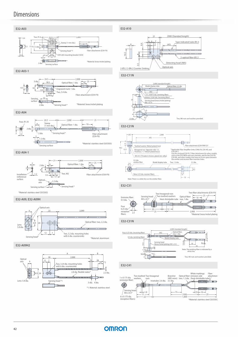
Dimensions
0.4 1.8
10
11
3.2
2
25
20.5 2,000
103 dia.
3.4 3.2R1.6
17.64.3
E32-A03
E39-L83 mounting bracket (SUS)
Sensing surface2 dia.
Fiber attachment (E39-F9)Sensing head *1
Stamp (1 mm dia.)
*Material: brass/nickel plating
Two, R1.6
1312.5
3
18.5
6.53
2,00024.5
10 25
4.5 103.5
E32-A03-1
Two, 3.4 dia.Engraved mark: 1 dia.
Optical fiber: 1 dia.
Fiber attachment (E39-F9)
2 dia.
Sensing surface
Sensing head *
3 dia.
*Material: brass/nickel plating
222
4
20.5 2,000 25
10
2 dia.
E32-A04
Four, R1.35Stamp (1 mm dia.)
2 dia. Fiber attachment (E39-F9)
Sensing head *
Optical fiber: 1 dia.
1.2 dia.
*Material: stainless steel (SUS303)Sensing surface
1.2 dia.
3.5
2,000
17
21
1.2
2 4
10
2
2510
2.5
2 dia.
92
E32-A04-1
Sensing head *
Two, M2Installation (reference) surface
Sensing surface
Optical axis
Fiber attachment (E39-F9)
Optical fiber: 1 dia.
*Material: stainless steel (SUS303)
2,000
12
9
7
23
208.9
E32-A09, E32-A09H
Sensing head**Material: aluminium
Optical fiber: two, 2.2 dia.Lens: 5.8 dia.
Optical axis
Two, 3.2 dia. mounting holes with 6 dia. countersinks
B
712
30
A
52,000
28139
248.9
*2
E32-A09H2
Sensing head *1
2.8 dia. flexible tubes*
Two, 3.24 dia. mounting holes with 6 dia. countersinks
Lens: 5.8 dia.
Optical axis
5 dia. 4 dia.
2.2 dia.
*1. Material: stainless steel
(45)4
16.5
21
628.
4
83.
5
4 7
6
2-Ø3.2 2-Ø6.2 Counter Sinking
2-optical fiber Ø2.2
Detecting head (ABS)
Type indicated tube Ø3.3
2000 (Standard length)
Optical axis
E32-A10
1.5 10
10
81
3
618
(45)
E32-C11N
Sixteen, 0.265 dia. (receiving fiber)
151, 0.0075 dia. (emitting fiber)
12 dia.
Sensing head (brass/nickel plating) M6 × 0.75
Model display tube Optical fiber, 2.2 dia.
Two, M6 nuts and washers provided.
2,000 (standard length)
E32-C21N
Toothed washer (Nickel-plated iron)
Hexagonal nut Opposite side: 5.5, Thickness: 1.7 (Nickel-plated brass)
M3×0.5 (Trivalent chrome-plated zinc alloy)
Fiber attachment (E39-F9W13)*
2.4
Nine, 0.25 dia. receiver fibers
0.5 dia.emitter fiber Model display tube Two, 1.3 dia. 2.2 dia.
4.5
4
Note: There is a white line on the emitter fiber.
(8.1) 2,000
(45)
18.5
7
13
6
12.5 Applicable Fiber Amplifier Units: E3NX-FA, E3X-HD, and E3X-DA-S.Use the enclosed E39-F9-7 Fiber Attachment for other models, such as the E3X-MDA with two channels, and for the E3X-SD, E3X-NA, and other models that have an 8-mm space between the emitter and receiver fiber insertion holes.
*
1025
25 2,0001220
2.5
E32-C31
Two fiber attachments (E39-F9)
Heat-shrinkable tubeOptical fiber: two, 1 dia.
*Material: brass/nickel plating
Emission fiber: 0.5 dia.
Four 0.25 dia. reception fibers
Two hexagonal nutsTwo toothed washersSensing head:
M3 x 0.5*
2510 0.5
(45)
1
13.5
7 2.5
5.5
5
E32-C31N
6.5 dia.
2,000 (standard length)
Two, M3 nuts and washers provided.
3.6
dia.
2.2
dia.
0.5 dia. (emitting fiber)
Four, 0.25-dia. (receiving fiber)
Sensing head (brass/nickel plating) M3 × 0.5
Model display tube
Optical fiber, two, 1-dia.
Note: The emitting fiber is indicated by a white line.
171.8
22 1,000
15 1025(100)
(5)
E32-C41
Irraxtube: 2.6 dia.
Brancher (ABS resin): 3.5 dia.
Optical fiber: two, 1.2 dia.
White markings: emission side (heat-shrinkable tube)
Fiber attachmentTwo toothed
washers
Sensing head: M3 x 0.5*
1 x 0.175 dia.(emission fiber)
6 x 0.175 dia.(reception fibers)
Two hexagonal nuts
*Material: stainless steel (SUS303)
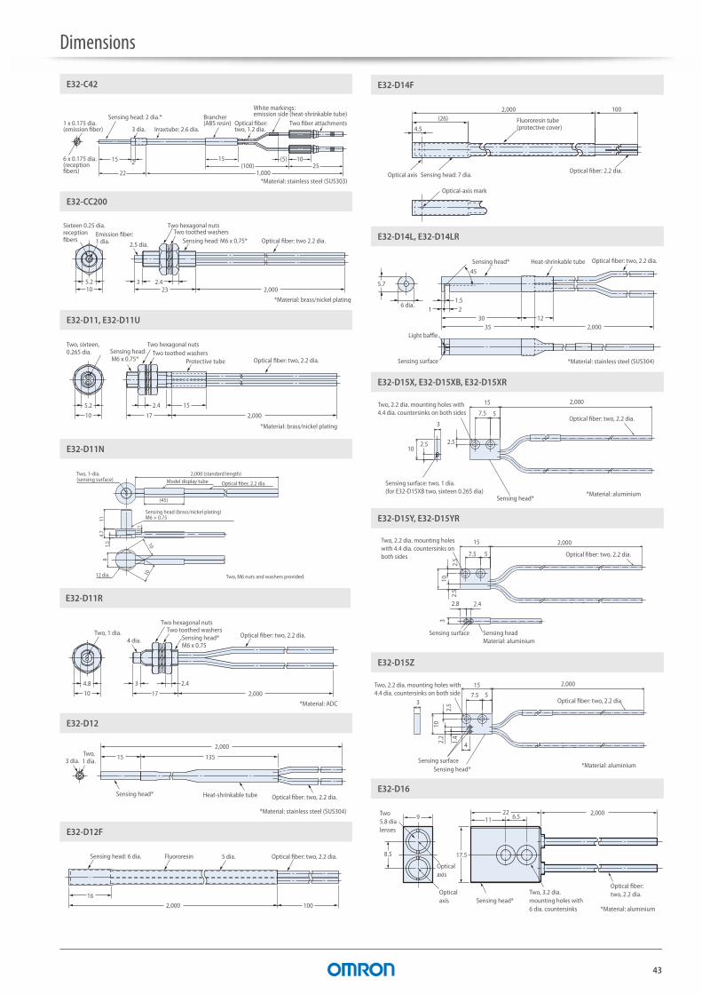
Dimensions
43
15 2
1,000
15 1025(100)
(5)
22
E32-C42
*Material: stainless steel (SUS303)
Two fiber attachments1 x 0.175 dia.(emission fiber)
6 x 0.175 dia.(reception fibers)
Irraxtube: 2.6 dia.Optical fiber: two, 1.2 dia.
Brancher (ABS resin)
White markings: emission side (heat-shrinkable tube)
3 dia.
Sensing head: 2 dia.*
5.210 23
3 2.42,000
E32-CC200
2.5 dia.
Two hexagonal nutsTwo toothed washers
Sensing head: M6 x 0.75* Optical fiber: two 2.2 dia.Emission fiber: 1 dia.
Sixteen 0.25 dia. reception fibers
*Material: brass/nickel plating
5.2
10 17
2.4 15
2,000
E32-D11, E32-D11U
Two, sixteen, 0.265 dia. Sensing head:
M6 x 0.75*
Two hexagonal nutsTwo toothed washers
Protective tube Optical fiber: two, 2.2 dia.
*Material: brass/nickel plating
1.5
4.7
11
1
10
10
8
(45)
E32-D11N
Two, M6 nuts and washers provided.
2,000 (standard length)
12 dia.
Two, 1-dia. (sensing surface)
Sensing head (brass/nickel plating) M6 × 0.75
Model display tube Optical fiber, 2.2 dia.
4.8 2.43
17 2,00010
E32-D11R
Two, 1 dia.4 dia.
Two hexagonal nutsTwo toothed washers
Sensing head*M6 x 0.75
Optical fiber: two, 2.2 dia.
*Material: ADC
2,000
13515
E32-D12
Two,1 dia.3 dia.
Heat-shrinkable tube Optical fiber: two, 2.2 dia.
*Material: stainless steel (SUS304)
Sensing head*
2,000
16
100
E32-D12F
Sensing head: 6 dia. Fluororesin 5 dia. Optical fiber: two, 2.2 dia.
1002,000
4.5
(26)
E32-D14F
Fluororesin tube (protective cover)
Optical-axis mark
Optical axis Sensing head: 7 dia.Optical fiber: 2.2 dia.
5.7
1.5
45
1 230
3512
2,000
E32-D14L, E32-D14LR
6 dia.
Sensing surface
Light baffle
Optical fiber: two, 2.2 dia.Heat-shrinkable tubeSensing head*
*Material: stainless steel (SUS304)
Optical fiber: two, 2.2 dia.
Sensing head*
Sensing surface: two, 1 dia.(for E32-D15XB two, sixteen 0.265 dia)
57.5
15 2,000
3
102.5 2.5
*Material: aluminium
Two, 2.2 dia. mounting holes with 4.4 dia. countersinks on both sides
E32-D15X, E32-D15XB, E32-D15XR
2.5
5
10
7.5
15 2,000
2.5
3
2.8 2.4
E32-D15Y, E32-D15YR
Optical fiber: two, 2.2 dia.
Two, 2.2 dia. mounting holeswith 4.4 dia. countersinks on both sides
Sensing surface Sensing headMaterial: aluminium
2.5
57.5
15 2,000
3
1.4
2.2
10
4
E32-D15Z
Optical fiber: two, 2.2 dia.
Sensing surfaceSensing head*
*Material: aluminium
Two, 2.2 dia. mounting holes with 4.4 dia. countersinks on both side
8.5
922
17.5
11 6.5 2,000
E32-D16
Two, 3.2 dia. mounting holes with 6 dia. countersinks
Optical axis
Optical axis
Two 5.8 dia lenses
Sensing head*
Optical fiber: two, 2.2 dia.
*Material: aluminium
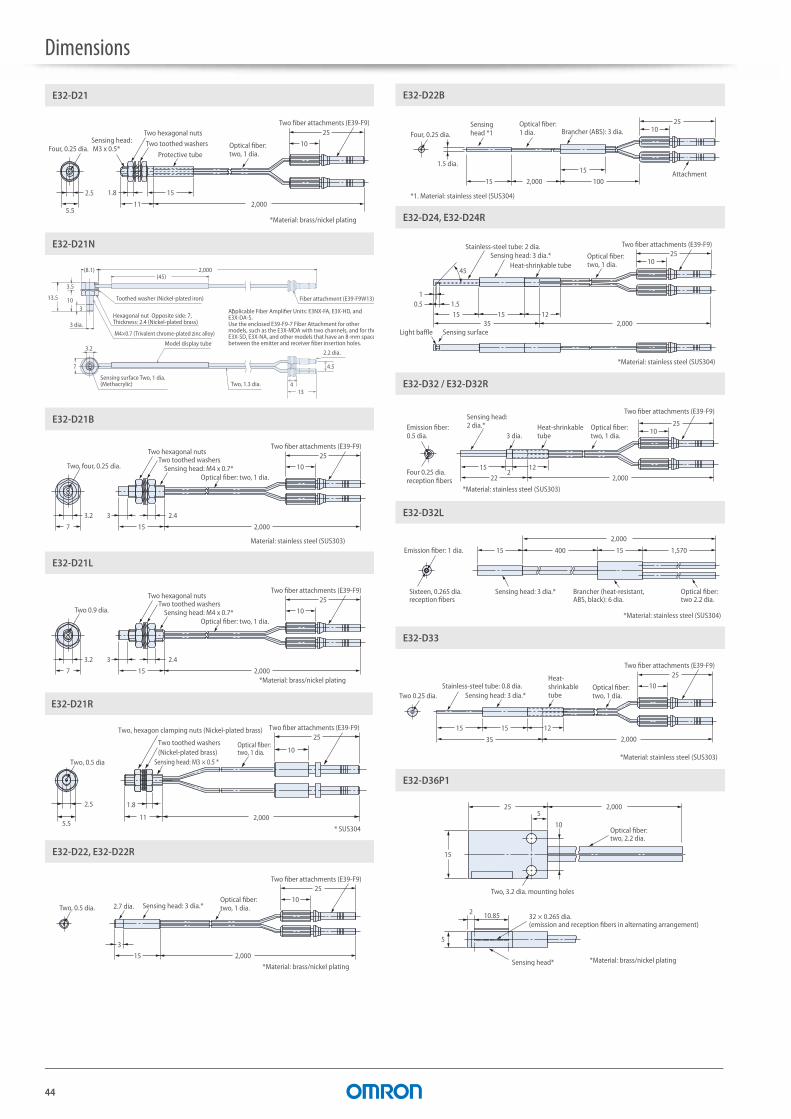
Dimensions
44
5.5
25
10
2.5 151.8
11 2,000
E32-D21
Two fiber attachments (E39-F9)
Four, 0.25 dia.
Two hexagonal nutsTwo toothed washers
Protective tubeOptical fiber:two, 1 dia.
Sensing head: M3 x 0.5*
*Material: brass/nickel plating
E32-D21N
4
Fiber attachment (E39-F9W13)*
3
3 dia.
Toothed washer (Nickel-plated iron)
Hexagonal nut Opposite side: 7, Thickness: 2.4 (Nickel-plated brass)
M4×0.7 (Trivalent chrome-plated zinc alloy)
3.2
Sensing surface Two, 1 dia.(Methacrylic)
Model display tube
Two, 1.3 dia.
2.2 dia.
4.5
2,000(45)
(8.1)
13
13.5
3.5
10
7
Applicable Fiber Amplifier Units: E3NX-FA, E3X-HD, and E3X-DA-S.Use the enclosed E39-F9-7 Fiber Attachment for other models, such as the E3X-MDA with two channels, and for theE3X-SD, E3X-NA, and other models that have an 8-mm spacebetween the emitter and receiver fiber insertion holes.
*
3.2 2.43
15 2,0007
10
25
E32-D21B
Two, four, 0.25 dia.
Two hexagonal nutsTwo toothed washers
Sensing head: M4 x 0.7*Optical fiber: two, 1 dia.
Two fiber attachments (E39-F9)
Material: stainless steel (SUS303)
3.2 2.43
15 2,0007
10
25
E32-D21L
Two 0.9 dia.
Two hexagonal nutsTwo toothed washers
Sensing head: M4 x 0.7*Optical fiber: two, 1 dia.
Two fiber attachments (E39-F9)
*Material: brass/nickel plating
E32-D21R
2.5
5.5
Optical fiber:two, 1 dia.
11 2,000
Sensing head: M3 × 0.5 *
Two toothed washers (Nickel-plated brass)
Two, hexagon clamping nuts (Nickel-plated brass)
Two, 0.5 dia
1.8
10
25Two fiber attachments (E39-F9)
* SUS304
3
15 2,000
25
10
E32-D22, E32-D22R
2.7 dia. Sensing head: 3 dia.*Optical fiber: two, 1 dia.
Two fiber attachments (E39-F9)
*Material: brass/nickel plating
Two, 0.5 dia.
15 1002,000
15
2510
E32-D22B
1.5 dia.
Four, 0.25 dia.Sensing head *1
Optical fiber: 1 dia. Brancher (ABS): 3 dia.
Attachment
*1. Material: stainless steel (SUS304)
3515 1215
10.5 1.5
2,000
1025
45
E32-D24, E32-D24R
Two fiber attachments (E39-F9)
Heat-shrinkable tubeOptical fiber: two, 1 dia.
Sensing head: 3 dia.*Stainless-steel tube: 2 dia.
Light baffle Sensing surface
*Material: stainless steel (SUS304)
1025
1522 2,000
122
E32-D32 / E32-D32R
Two fiber attachments (E39-F9)
Emission fiber: 0.5 dia.
Four 0.25 dia. reception fibers
Heat-shrinkable tube
Optical fiber: two, 1 dia.3 dia.
Sensing head: 2 dia.*
*Material: stainless steel (SUS303)
15 400 15 1,570
2,000
E32-D32L
Emission fiber: 1 dia.
Sixteen, 0.265 dia. reception fibers
Sensing head: 3 dia.* Brancher (heat-resistant, ABS, black): 6 dia.
Optical fiber: two 2.2 dia.
*Material: stainless steel (SUS304)
10
25
15
35 2,000
15 12
E32-D33
Stainless-steel tube: 0.8 dia.Two 0.25 dia. Sensing head: 3 dia.*
Heat-shrinkable tube
Optical fiber: two, 1 dia.
Two fiber attachments (E39-F9)
*Material: stainless steel (SUS303)
15
10
5
5
25 2,000
10.852
E32-D36P1
Two, 3.2 dia. mounting holes
Sensing head*
32 × 0.265 dia. (emission and reception fibers in alternating arrangement)
Optical fiber: two, 2.2 dia.
*Material: brass/nickel plating
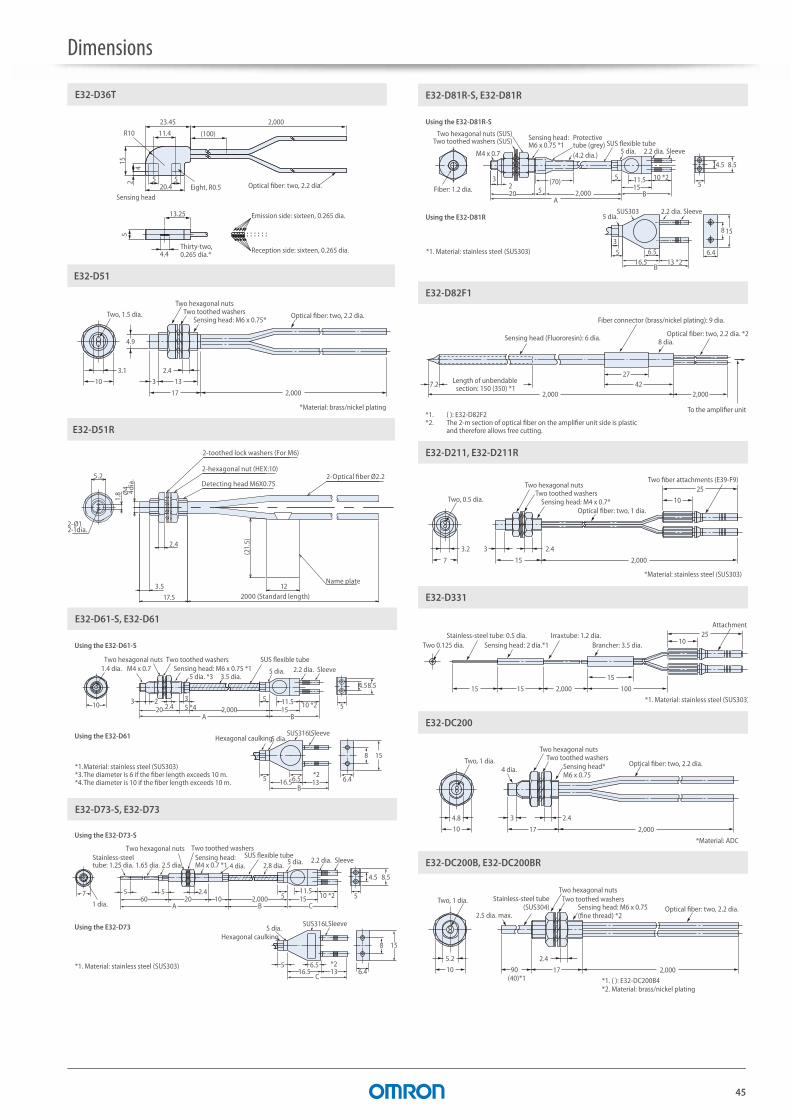
Dimensions
45
2,00015
13.25
4.4
R10 (100)
524
5
11.4
23.455
20.4
E32-D36T
Sensing head
Thirty-two, 0.265 dia.*
Optical fiber: two, 2.2 dia.
Reception side: sixteen, 0.265 dia.
Emission side: sixteen, 0.265 dia.
Eight, R0.5
3.1
4.9
2.4
133
17 2,000
10
E32-D51
Two, 1.5 dia.
Two hexagonal nutsTwo toothed washers
Sensing head: M6 x 0.75*Optical fiber: two, 2.2 dia.
*Material: brass/nickel plating
17.5
3.5
Ø4
4di
a.
12
(21.
5)
2000 (Standard length)
5.2
1.8
2.4
Detecting head M6X0.75
2-hexagonal nut (HEX:10)2-Optical fiber Ø2.2
Name plate
2-Ø12-1dia.
2-toothed lock washers (For M6)
E32-D51R
10
A B20 5 *4
3
2,000 1511.55
10 *2
4.5
5
8.5
3 22.4
B16.56.55 *2
13
8
6.4
15
E32-D61-S, E32-D61
5 dia. 2.2 dia. Sleeve5 dia. *3 3.5 dia.
SUS flexible tubeTwo toothed washersSensing head: M6 x 0.75 *11.4 dia. M4 x 0.7
*1. Material: stainless steel (SUS303)*3. The diameter is 6 if the fiber length exceeds 10 m.*4. The diameter is 10 if the fiber length exceeds 10 m.
5 dia.Hexagonal caulkingSUS316L
Using the E32-D61-S
Using the E32-D61 Sleeve
Two hexagonal nuts
5760 20 10 2,000
16.5*213
5
A B
C
2.4
5 6.56.4
158
C1511.5
5 10 *2
4.5
5
8.5
E32-D73-S, E32-D73
Sleeve5 dia.
4 dia. 2.8 dia.
Hexagonal caulking
SUS316L
SUS flexible tubeTwo toothed washersTwo hexagonal nuts
Sensing head: M4 x 0.7 *12.5 dia.1.65 dia.
Stainless-steeltube: 1.25 dia.
*1. Material: stainless steel (SUS303)
5 dia. 2.2 dia. Sleeve
Using the E32-D73-S
Using the E32-D73
1 dia.
6.4
8 15
13 *26.5
16.5B
5
3
3220 5
(70)
A
(4.2 dia.)
2,000 B1511.55 10 *2
4.5
5
8.5
E32-D81R-S, E32-D81R
SUS303 Sleeve2.2 dia.5 dia.
*1. Material: stainless steel (SUS303)
Fiber: 1.2 dia.
M4 x 0.7
Sensing head: M6 x 0.75 *1Two toothed washers (SUS)
Two hexagonal nuts (SUS) Protective tube (grey)
5 dia. 2.2 dia. SleeveSUS flexible tube
Using the E32-D81R-S
Using the E32-D81R
2,0007.2
2,000
2742
E32-D82F1
Sensing head (Fluororesin): 6 dia.
Fiber connector (brass/nickel plating): 9 dia.
Optical fiber: two, 2.2 dia. *2
To the amplifier unit
Length of unbendable section: 150 (350) *1
*1. ( ): E32-D82F2*2. The 2-m section of optical fiber on the amplifier unit side is plastic and therefore allows free cutting.
8 dia.
3.2 2.43
15 2,0007
10
25
E32-D211, E32-D211R
Two, 0.5 dia.
Two hexagonal nutsTwo toothed washers
Sensing head: M4 x 0.7*Optical fiber: two, 1 dia.
Two fiber attachments (E39-F9)
*Material: stainless steel (SUS303)
1515 1002,000
15
2510
E32-D331
Two 0.125 dia.Stainless-steel tube: 0.5 dia.
Sensing head: 2 dia.*1 Brancher: 3.5 dia.
Attachment
*1. Material: stainless steel (SUS303)
Irraxtube: 1.2 dia.
4.8 2.43
17 2,00010
E32-DC200
Two, 1 dia.4 dia.
Two hexagonal nutsTwo toothed washers
Sensing head*M6 x 0.75
Optical fiber: two, 2.2 dia.
*Material: ADC
2,00017
2.45.2
10 90(40)*1
E32-DC200B, E32-DC200BR
Two, 1 dia.
2.5 dia. max.
Two hexagonal nutsStainless-steel tube
(SUS304)Two toothed washers
Sensing head: M6 x 0.75 (fine thread) *2
Optical fiber: two, 2.2 dia.
*1. ( ): E32-DC200B4*2. Material: brass/nickel plating
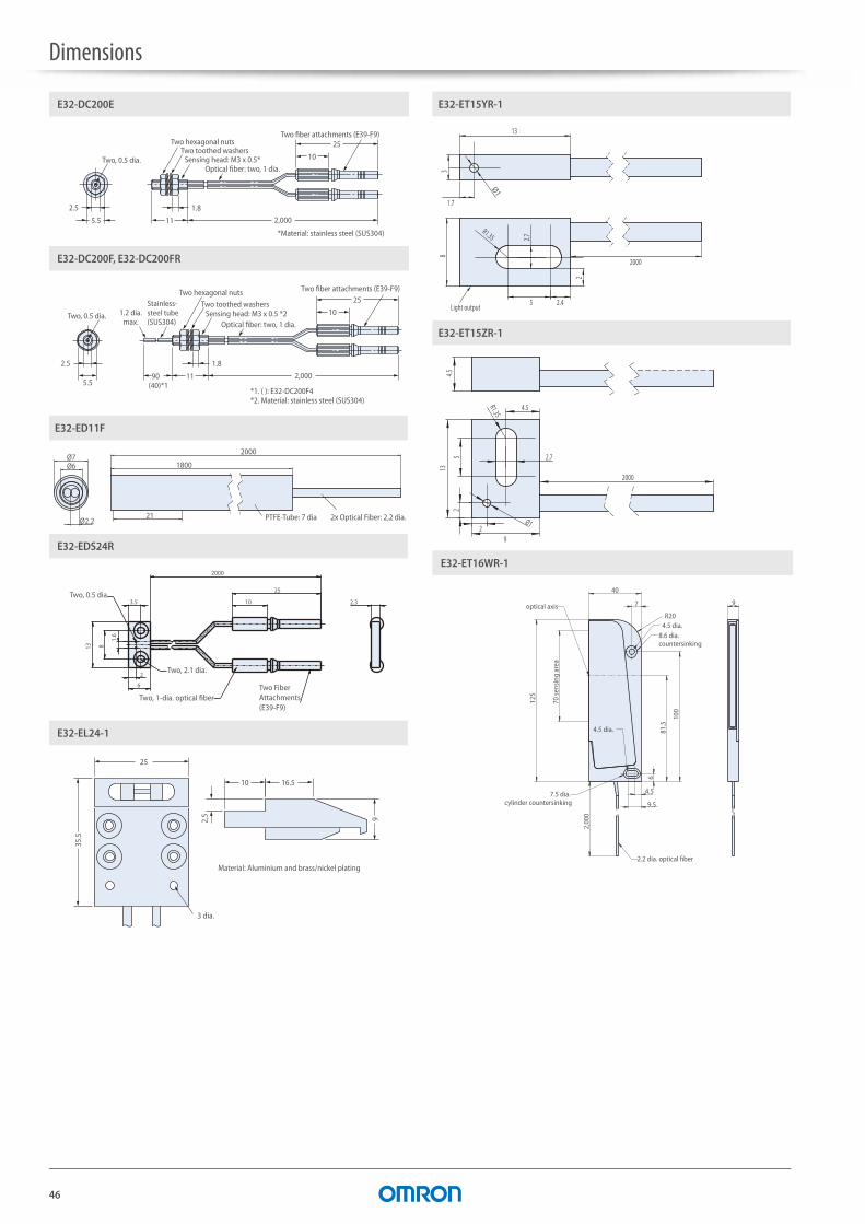
Dimensions
46
2.5
5.5 11
1.8
2,000
25
10
E32-DC200E
Two, 0.5 dia.
*Material: stainless steel (SUS304)
Two fiber attachments (E39-F9)Two hexagonal nuts
Two toothed washersSensing head: M3 x 0.5*
Optical fiber: two, 1 dia.
2.5
5.511 90
(40)*1
1.8
2,000
25
10
E32-DC200F, E32-DC200FR
Two, 0.5 dia.
Two fiber attachments (E39-F9)Two hexagonal nuts
1.2 dia.max.
Stainless-steel tube (SUS304)
Two toothed washersSensing head: M3 x 0.5 *2
Optical fiber: two, 1 dia.
*1. ( ): E32-DC200F4*2. Material: stainless steel (SUS304)
21
2000
1800
2x Optical Fiber: 2,2 dia.PTFE-Tube: 7 dia
Ø7
Ø2.2
Ø6
E32-ED11F
E32-EDS24R
Two, 0.5 dia.3.5
2000
25
10
2
6
Two, 2.1 dia.
Two, 1-dia. optical fiberTwo Fiber Attachments (E39-F9)
13 8
1.6
2.3
35.5
25
10 16.5
92,5
E32-EL24-1
3 dia.
Material: Aluminium and brass/nickel plating
E32-ET15YR-1
8
R1.35
2000
2
2.7
5 2.4Light output
13
3
1.7
Ø1
E32-ET15ZR-1
9
13
2.7
2000
R1.35
4.5
5
Ø12
24.5
40
7 9
9.5
4.5
6
81.5
2,00
0
125
100
E32-ET16WR-1
7.5 dia. cylinder countersinking
8.6 dia. countersinking
4.5 dia.
4.5 dia.
R20
2.2 dia. optical fiber
optical axis
70 se
nsin
g ar
ea
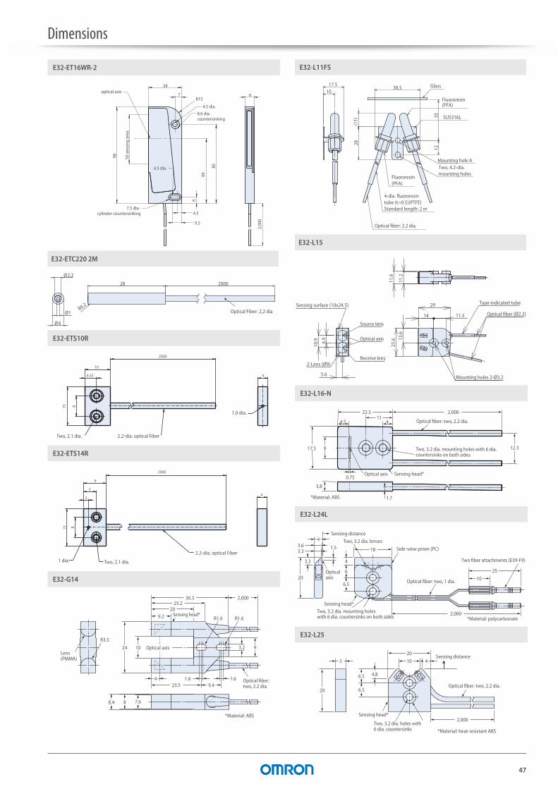
Dimensions
47
2,00
0
34
7 9
9.5
4.5
6
66
98
80
E32-ET16WR-2
7.5 dia. cylinder countersinking
8.6 dia. countersinking
4.5 dia.
R15
optical axis
50 se
nsin
g ar
ea
4.5 dia.
R0,2
200028
Optical Fiber: 2,2 dia
Ø2,2
Ø1
Ø4
E32-ETC220 2M
15 8
10
4.55
2000
4
E32-ETS10R
Two, 2.1 dia. 2.2-dia. optical Fiber
1.0 dia.
9
5
2
15 8
2000
4
E32-ETS14R
1 dia. Two, 2.1 dia.
2.2-dia. optical Fiber
1.6423.5 9.4
1.6
9.2
24
R3.5
10
2025.2
36.3 2,000
R1.6 R1.6
3.2 9
7.68.4 8
E32-G14
Lens (PMMA)
Optical axis
Sensing head*
Optical fiber: two, 2.2 dia.
*Material: ABS
E32-L11FS
1235
28
38.5
Mounting hole A
Glass10
17.5
SUS316L
(11)
Fluororesin(PFA)
Two, 4.2-dia.mounting holes
Fluororesin(PFA)
4-dia. fluororesintube (t=0.5)(PTFE)Standard length: 2 m
Optical fiber: 2.2 dia.
10.9 6.9
5.6
Source lens
Receive lens
Sensing surface (10x24.5)
Optical axis
2-Lens (Ø9)
29
14 11.5
25.6 13
.6
Optical fiber (Ø2.2)
Mounting holes 2-Ø3.2
11.2
11.6
Type indicated tube
E32-L15
411
22.5
17.5
4.5
3.8
9
0.75
1.7
2,000
12.3
E32-L16-N
Optical fiber: two, 2.2 dia.
Two, 3.2 dia. mounting holes with 6 dia. countersinks on both sides
Optical axis Sensing head*
*Material: ABS
10
25
18
2,000
4
6
3.3
3.64
3.31.5
206.5
E32-L24L
Two fiber attachments (E39-F9)
Side-view prism (PC)
Two, 3.2 dia. lenses
Optical fiber: two, 1 dia.
Sensing distance
Sensing head*
*Material: polycarbonateTwo, 3.2 dia. mounting holes with 6 dia. countersinks on both sides
Optical axis
2,000
20
10
6.5
5
4.8
6.520
4
E32-L25
Optical fiber: two, 2.2 dia.
Sensing head*
Two, 3.2 dia. holes with 6 dia. countersinks
Sensing distance
*Material: heat-resistant ABS

Dimensions
48
10
25
18
2,000
6
4
16 6.5
E32-L25L
Two fiber attachments (E39-F9)
Sensing distanceTwo, 3.2 dia. lenses
Optical fiber: two, 1 dia.
Sensing head*
Two, 3.2 dia. mounting holes with 6 dia. countersinks on both sides
*Material: polycarbonate
6.510.7
A B
13
302,000
18
5 4
18 8.9
E32-L64
Two, 2.9 dia. flexible tubes (stainless steel)
4 dia.
2.2 dia.
Two, 3.4 dia. mounting holes with 6.3 dia. countersinks
Sensing head *1 *1. Material: stainless steel (SUS303)
185
25
1 7
1121.7A B
513 *2
252,000
36
5.5
18
E32-L66
Two, 2.8 dia. flexible tubes (stainless steel)
4 dia.
2.2 dia.
Two, 3.2 dia. mounting holes with 6 dia. countersinks
Sensing head *1 *1. Material: stainless steel (SUS303)
E32-LD11/LD11 R
M6 × 0.75 (Trivalent chrome-plated zinc alloy)
2-2.2 dia.
Opposite side: 10, Thickness: 2.4 (Nickel-plated brass)Washers (Nickel-plated iron)
5 2,000 15
23
Sensing surface 2-1.5 dia.
E32-LD11N
Toothed washer (Nickel-plated iron)
Hexagonal nut Opposite side: 10, Thickness: 2.4 (Nickel-plated brass)
M6×0.75 (Trivalent chrome-plated zinc alloy)
2.35 5Sensing surface Two, 1.5 dia.(Methacrylic) Model display tube
Two, 2.2 dia.
2,000
(45)
(11.5)
15.8
10
4.8
11
E32-LR11NP
2,000
(45)
(11.5)
2.35
5
10
15.8
4.8
11
M6×0.75 (Trivalent chrome-plated zinc alloy)
Hexagonal nut Opposite side: 10, Thickness: 2.4 (Nickel-plated brass)
Toothed washer (Nickel-plated iron)
Sensing surface Two, 1.5 dia.(Optical filter) Model display tube
Two, 2.2 dia.
E32-LT11/LT11 R
2.2 dia.
M4 × 0.7 (Trivalent chrome-plated zinc alloy)
Lens (PMMA)
3.2
Sensing surface 2.3 dia.10
15 2,000
Opposite side: 7, Thickness: 2.4 (Nickel-plated brass)Washers (Nickel-plated iron)
E32-LT11N
M4×0.7 (Trivalent chrome-plated zinc alloy)
Hexagonal nut Opposite side: 7, Thickness: 2.4 (Nickel-plated brass)
Toothed washer (Nickel-plated iron)
3.2 Sensing surface 2.3 dia.(Methacrylic) Model display tube 2.2 dia.
(8.1)
(45)
2,000
14.4
4.4
10
7
28
13
23
11 2,0001.8
E32-M21
Sleeve
Sensing head: M3 x 0.35 *2Two hexagonal nuts
Two toothed washersSilicon tube *1 Four, 1 dia.
plastic fibers
*1. One set of silicon tubes is black and the other set is grey. Use this difference to distinguish between the emission and reception sides.
15.2
7.2
10
21.5
27 15
7
16 4(6)
8
E32-R16
Lens (PMMA)
Sensing head *1
Optical fiber: two, 2.2 dia.Standard length: 2 m
Two, M3 set screws (provided)
*1. Material: ABS

Dimensions
49
10
25
27.8
17.8
2.8 11
3
14
2,000
10
2.2
E32-R21
Two fiber attachments
Optical fiber: two, 1 dia.
Silicon tube
Two hexagonal nutsTwo washersSensing head*
Lens (PMMA)
M6 x 0.75
5 dia.
*Material: ABS
2.4 15
(14) 2,000
3.3
7
3.2
E32-T11, E32-T11U
Optical fiber: 2.2 dia.
Two hexagonal nutsTwo toothed washers
Protective tubeSixteen, 0.265 dia.
Sensing head: M4 x 0.7*
M2.6 x 0.45
*Material: brass/nickel plating
7
M2.6 × 0.45
M4 × 0.7
310
(45)
7
5.5
1
4.7
1.5
E32-T11N
Four, M4 nuts and washers provided.
2,000 (standard length)
8.4 dia.
1 dia. (sensing surface)
Optical fiber, 2.2 dia.Model display tube
Sensing head (brass/nickel plating)
3.2 3 2.4
14 2,0007
E32-T11R
M2.6 x 0.451 dia.
Two hexagonal nutsTwo toothed washers
Sensing head: M4 x 0.7*
*Material: brass/nickel plating
Optical fiber: 2.2 dia.
3 11
(14) 2,000
E32-T12, E32-T12R
1 dia. 2.4 dia. Sensing head: 3 dia.* Optical fiber: 2.2 dia.
*Material: brass/nickel plating
3 11
(14) 2,000
E32-T12B
Sixteen, 0.265 dia. 2.4 dia. Sensing head: 3 dia.* Optical fiber: 2.2 dia.
*Material: brass/nickel plating
20
2,000 100
E32-T12F
Sensing head: 5 dia. Fluororesin 4 dia.
Optical fiber: 2.2 dia.
Lens: 4 dia.
3 11
(14) 2,000
E32-T12L
1.4 dia. 2.4 dia. Sensing head: 3 dia.* Optical fiber: 2.2. dia.
*Material: brass/nickel plating
10 0.2
9.2
78
2.5
10.5
R3.5
8.2
16 11.2 2,000
7.68
E32-T14
Optical axis Two, 3.2 dia.
Heat-resistant ABSLens (PMMA) 4.4 dia.Nitrile rubber
Optical fiber: 2.2 dia.
(21)
2,000 100
4.5
E32-T14F
Optical axis
Sensing head: 5 dia. Fluororesin 4 dia. Optical fiber: 2.2 dia.
35
30
1.5
1.5
2.8
1
45
12
2,000
E32-T14L, E32-T14LR
Sensing surface
3 dia.
Heat-shrinkable tubeSensing head: 3 dia.* Optical fiber: 2.2 dia.
*Material: stainless steel (SUS304)
57.53
15 2,000
82.51.5
E32-T15X
Two, 2.2 dia. mounting holes with 4.4 dia. countersinks on both sides
Sensing headMaterial: aluminium
Sensing surface 1 dia.
Optical fiber: Two, 2.2 dia.
57.53
15 2,000
8 1.5 2.5
E32-T15XB
Optical fiber: 2.2 dia.
Two, 2.2 dia. mounting holes with 4.4 dia. countersinks on both sides
Sensing headMaterial: aluminium
Sensing surface: Sixteen, 0.265 dia.
57.515 2000
4
8
1.5
2.5
3
E32-T15Y, E32-T15YR
Optical fiber: two, 2.2 dia.
Two, 2.2 dia. mounting holes with 4.4 dia. countersinks on both sides
Sensing headMaterial: aluminium
Sensing surface
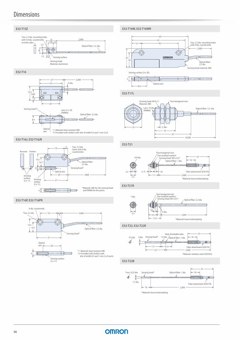
Dimensions
50
2,0007.5 515
4
3
8
2.5
1.5
E32-T15Z
Sensing headMaterial: aluminium
Optical fiber: 2.2. dia.
Two, 2.2 dia. mounting holes with 4.4 dia. countersinks on both sides
Sensing surface
27 2,000
25
20
8.4
15.58.85
3
E32-T16
6 dia.
Sensing head*1
Optical axis
Lens (2 x 10)(PMMA)
Optical fiber: 2.2 dia.
*1. Material: heat-resistant ABS*2. Provided with stickers with slits of width 0.5 and 1 mm (2 of
4
3.3
27
20
*2
14.510.7
4
2000
19
E32-T16J, E32-T16JR
Sensing surface (2 x 11)
Receiver Emitter
Sensing surface (2 x 11)
Sensing head*
Optical axis
Two, 3.2 dia. holes with 6 dia. countersinks
Optical fiber: 2.2 dia.
*Material: ABS for the sensing head and PMMA for the prism.
19
27
14.510.7
42,000
4
20
E32-T16P, E32-T16PR
Two, 3.2 dia.
6 dia. countersink
Sensing head*
Optical fiber: 2.2 dia.
Sensing surface(2 x 11)
Optical axis
*1. Material: heat-resistant ABS*2. Provided with stickers with slits of width 0.5 and 1 mm (2 of each).
18
69
6545
2,000
12
23
18.5
5
E32-T16W, E32-T16WR
Sensing surface (3 x 30)
Two, 3.2 dia. mounting holes with 6 dia. countersinks
Optical fiber: 2.2 dia.
Optical axis
Sensing head material: ABS
519
23
42
10,000
E32-T17L
Lens: 10 dia. (PMMA)
Sensing head: M14 x 1Material: ABS
Two hexagonal nuts
Optical fiber: 2.2. dia.
2.5
5.511
1.8(1.7)
25
10
2,000
E32-T21
0.9 dia.
Two hexagonal nuts
Fiber attachment (E39-F9)
Sensing head: M3 x 0.5*Optical fiber: 1 dia.
Two toothed washers
*Material: brass/nickel plating
2,0009.5
13.5
5.5
1.83 dia.
E32-T21R
1 dia.Two hexagonal nutsTwo toothed washersSensing head: M3 x 0.5*
*Material: brass/nickel plating
Optical fiber: 2.2 dia.
17
22 2,000
12
25
10
E32-T22, E32-T22R
0.5 dia. 2 dia.
Fiber attachment (E39-F9)
Heat-shrinkable tubeSensing head*
*Material: stainless steel (SUS303)
Optical fiber: 1 dia.1.4 dia.
10
25
10
2,000
E32-T22B
1.5 dia.Fiber attachment (E39-F9)
Four, 0.25 dia. Sensing head* Optical fiber: 1 dia.
*Material: brass/nickel plating
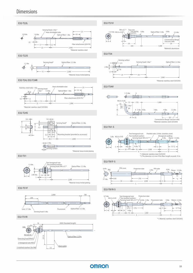
Dimensions
51
25
10
(2)17
22 2,000
12
E32-T22L
Fiber attachment (E39-F9)
*Material: stainless steel
0.9 dia. 1.8 dia.
Sensing head: 2 dia.*
Optical fiber: 1 dia.Heat-shrinkable tube
15 2,000
E32-T22S
3 dia.
1.7 dia.Sensing head* Optical fiber: 2.2 dia.
*Material: brass/nickel plating
35 2,00015
1.50.51
15 12
25
1045
E32-T24, E32-T24R
Fiber attachment (E39-F9)
Stainless-steel tube: 1 dia.Heat-shrinkable tube
1.4 dia. Optical fiber: 1 dia.
*Material: stainless steel (SUS304)
Sensing head: 2 dia.*
3.210
1.8
20.5
2
2,000
11
3
0.4
17.6 3.2
E32-T24S
Mounting bracket (provided as accessory)
Optical fiber: 2.2 dia.Sensing head*
2 dia.
Sensing surface
3.5 dia.
*Material: brass/nickel plating
152.42.85 dia.
17
17 2,000
E32-T51
1.5 dia.Optical fiber: 2.2 dia.
Two hexagonal nutsTwo toothed washers
Sensing head: M4 x 0.7*
*Material: brass/nickel plating
100
(20)
2,000
E32-T51F
Lens: 3.7 dia. Optical fiber: 2.2 dia. FluororesinSensing head: 5 dia.
3.2 3
14
2.4
12
2000 (Standard length)
(21.
5)
Detecting head M4x0.7
2-hexagonal nuts HEX:7
2-toothed washers (for M4)
1dia.
M2.6x0.45Optical fiber 2.2Dia.
Name plate
E32-T51R
8 3
M2.6 x 0.45M4 x 0.7 *
20(30) 1,000
26
E32-T51V
Two spring washers
4 dia. Optical fiber: 3 dia. 4 dia.
Connected to flange (vacuum side)
2.2 dia.Two nuts
1.15 dia.
*Material: aluminium
1
1.745
2.5
45
25 20
2,000
E32-T54
2 dia.
Sensing surfaceSensing head: 3 dia.*
*Material: stainless steel (SUS303)
Optical fiber: 2.2 dia.
18
4.5
312
M2.6 x 0.45
4
4
R9
(3)
(15) 1,000
26
E32-T54V
1.15 dia.
3 dia.*
4 dia. 4 dia.
Connected to flange (vacuum side)
3 dia. 2.2 dia.5 dia.
*Material: stainless steel (SUS304)
720
32.4 10 2,000 25
5
B
13 *2
A
E32-T61-S
1 dia.
4 dia. *3
4 dia. Sleeve
Flexible tube: 2.8 dia. (stainless steel)Hexagonal caulking
Two hexagonal nutsTwo toothed washers
Sensing head: M4 x 0.7 *1M2.6 x 0.45
*1. Material: stainless steel (SUS303)*3. The diameter is 6 mm if the fiber length exceeds 10 m.
2.2 dia.
30(0.8)
2,000
13
*2(70)
B255
A
(R6)
E32-T81F-S
3.7 dia.
4 dia. Sleeve 2.2 dia.Protective tube PFA tube
2 dia.PFA cover6 dia.
720
3 2.410 2,000
5
B
2513 *2
A
(75)
E32-T81R-S
0.7 dia.
4 dia.
4 dia.2 dia.3.6 dia. Fluororesin tube
Protective tubeTwo hexagonal nutsTwo toothed washersSensing head: M4 x 0.7 *1
M2.6 x 0.45
*1. Material: stainless steel (SUS303)
Sleeve 2.2 dia.
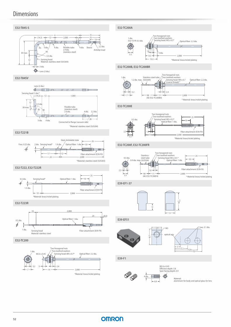
Dimensions
52
1325B
5
A12(14.2)
6
12
2,000
R5
90
E32-T84S-S
Lens (2 dia.)
30 max.
3 dia.
Antislip treadSleeve4 dia.4 dia.3 dia.
3.5 dia.
Sensing head Material: stainless steel (SUS303)
Flexible tube: 2.9 dia. (stainless steel)
2.2 dia.
(14.2)
12
6R5 90
12 1,000
26
E32-T84SV
Sensing head: 3 dia.*
Lens (2 dia.)
3 dia.
3.5 dia.Flexible tube (stainless steel): 2.9 dia.
4 dia.
4 dia. 2.2 dia.
Connected to flange (vacuum side)
30 max.
*Material: stainless steel (SUS304)
17
22 2,000
12
25
10
E32-T221B
Four, 0.25 dia. Sensing head*
*Material: stainless steel (SUS303)
Fiber attachment (E39-F9)
Optical fiber: 1 dia.1.4 dia.
Heat-shrinkable tube
2 dia.
10
1.5 dia.
25
10
2,000
E32-T222, E32-T222R
Fiber attachment (E39-F9)
Sensing head*0.5 dia. Optical fiber: 1 dia.
*Material: brass/nickel plating
10
25 (0.5)
2,000
E32-T223R
Sensing headMaterial: stainless steel
0.5 dia.
Fiber attachment (E39-F9)
Optical fiber: 1 dia.
1 dia.
3.2 3 2.4
14 2,0007
E32-TC200
M2.6 x 0.451 dia.
Two hexagonal nutsTwo toothed washers
Sensing head: M4 x 0.7*
*Material: brass/nickel plating
Optical fiber: 2.2 dia.
2,0009.5
13.5
5.5
1.8
E32-TC200A
1 dia.E32-T21R: 0.5 dia.
3 dia.
Two hexagonal nutsTwo toothed washersSensing head: M3 x 0.5*
*Material: brass/nickel plating
Optical fiber: 2.2 dia.
3.2
11
2.4
2,0007
E32-TC200B, E32-TC200BR
1.2 dia. max.Stainless-steel tube (SUS304)
1 dia.Two hexagonal nutsTwo toothed washers
90( 40: E32-TC200B4)
Sensing head: M4 x 0.7(coarse thread) *
Optical fiber: 2.2 dia.
* Material: brass/nickel plating
11 2,000
10
25
1.8
5.5
2.5
E32-TC200E
Two hexagonal nutsTwo toothed washers
Fiber attachment (E39-F9)
0.5 dia. Sensing head: M3 x 0.5*Optical fiber: 1 dia.
*Material: brass/nickel plating
1.8
5.5
2.5
2,00011
10
25
E32-TC200F, E32-TC200FR
Two hexagonal nuts
0.9 dia. max.0.5 dia.
Stainless-steel tube (SUS304)
Two toothed washers
90(40: E32-TC200F4)
Fiber attachment (E39-F9)
Sensing head: M3 x 0.5 *Optical fiber: 1 dia.
* Material: brass/nickel plating
9
9
16 0 -0
.2
E39-EF1-37
1512,67.1
3
5.6
8.7
E39-EF51
two. 3.1 dia.
optical axis
M3
8.9
E39-F1
4 dia.
M2.6 x 0.45Effective depth: 3.8Spot-facing depth: 0.9
Material: aluminium for body and optical glass for lens

Dimensions
53
8.9
6
E39-F1V
0.5 dia. hole
M2.6 x 0.45Effective depth: 3.8Spot-facing depth: 0.9
4 dia.
9.2
5.7
E39-F2
4 dia.
2.8 dia.
M2.6Effective depth: 3.2Spot-facing depth: 0.9
Material: aluminium for body and optical glass for lens
23
13
3
E39-F3A
M2 x 2 allen-head set screw (for securing the fiber)
2.1 dia.
6 dia. 4 dia.
Lens surface (lens diameter: 3.7 mm)
Material: aluminium for body and optical glass for lens
6.516.5
E39-F3A-5
Lens surface (lens diameter: 3.7 mm)
Straight knurling
5 dia.4 dia.
2.1 dia.
M3 x 0.5 Effective screw length: 3
Material: aluminium for body and optical glass for lens.
25.2Lens surface (lens diameter: 4.8 mm)
Material: aluminium for body and optical glass for lens.
M3 x 0.5 depth: 4.424.1
5.5 dia.6 dia.
E39-F3B
8 45
24.5
E39-F4
Standard-fiber insertion hole Thin-fiber insertion hole
25
10 11.7
E39-F9
1.1 dia. Mark indicating position of insertion into amplifier unit
3.6 dia.
(2.2 dia.)
26 12.8
E39-F10
3.8 dia. 3 dia.
Fiber: 2.2 dia
Fiber: 2.2 dia. Splice *1
Retention clip *2
Retention clip *2
*1. Material: polyester*2. Material: brass
10.8
27
42.5
10 10R5
R7.5
R12.5
R10
E39-F11
2
32.6(48.6)
8
29.63.2
7.6
9.2
27.433.8 22.4 20.4
E39-F13, E39-F14, E39-F15
Four, 0.8
Four, R0.8
Four, 6 dia.
Four, A (See note.)
522.5
Ø7.
8
5.9
Lens dimension Ø7.2 M4 x 0.7 depth: 6C1
E39-F16
5.5
30
Ø10
8
8
M6 x 0.75 Depth: 3.9Lens dimension Ø9.4
E39-F18
6 dia.
12L
12
E39-F32A, E39-F32B
3 dia.End cap *1
Tube *2
*1. Material: brass/nickel plating*2. Material: stainless steel (SUS304)
(4.6 dia.)Head connector *1M3 x 0.5; depth: 4
12L
12
E39-F32C
7 dia.
End cap *1 4 dia.(5.6 dia.)Head connector *1M4 x 0.7; depth: 4
Tube *2
*1. Material: brass/nickel plating*2. Material: stainless steel (SUS304)
12L
12
E39-F32D
8.5 dia.
5 dia.End cap *1(7 dia.)Head connector *1M6 x 0.75; depth: 4
Tube *2
*1. Material: brass/nickel plating*2. Material: stainless steel (SUS304)
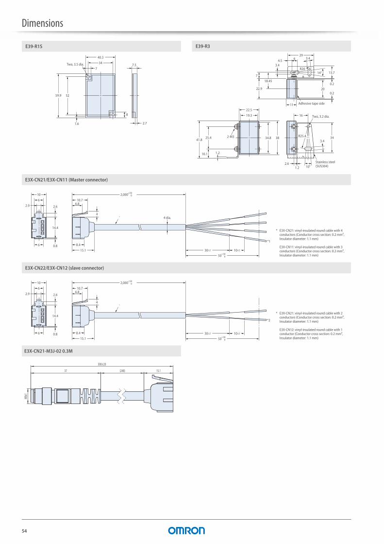
Dimensions
54
E39-R1S
34
40.3
5259.9
2.7
8
1.6
7.57
Two, 3.5 dia.
E39-R3
29
4.5 6
R203.4
7
18.45
22.9
11
200.2
0.2
16
22.5
19.3
343834.82-M341.8
10.1 1.2
25.4 R25.43.4
10°1.22.6 Stainless steel
(SUS304)
Adhesive tape side
Two, 3.2 dia.
13.714°
3.4
E3X-CN21/E3X-CN11 (Master connector)
14.4
2.6
6
2.9
10
0.8 8.4
6.810.7
50+50 0
30±2
4 dia.
10±2
4
15.1
6
2,000+50 0
*
*1
* E3X-CN21: vinyl-insulated round cable with 4 conductors (Conductor cross section: 0.2 mm², Insulator diameter: 1.1 mm)
E3X-CN11: vinyl-insulated round cable with 3 conductors (Conductor cross section: 0.2 mm², Insulator diameter: 1.1 mm)
E3X-CN22/E3X-CN12 (slave connector)
14.4
2.6
6
2.9
10
0.8 8.4
6.810.7
50+50 0
30±2 10±2
4
15.1
6
2,000+50 0
*
*2
* E3X-CN21: vinyl-insulated round cable with 2 conductors (Conductor cross section: 0.2 mm², Insulator diameter: 1.1 mm)
E3X-CN12: vinyl-insulated round cable with 1 conductor (Conductor cross section: 0.2 mm², Insulator diameter: 1.1 mm)
E3X-CN21-M3J-02 0.3M
300±20
37 (248) 15.1
M8x1
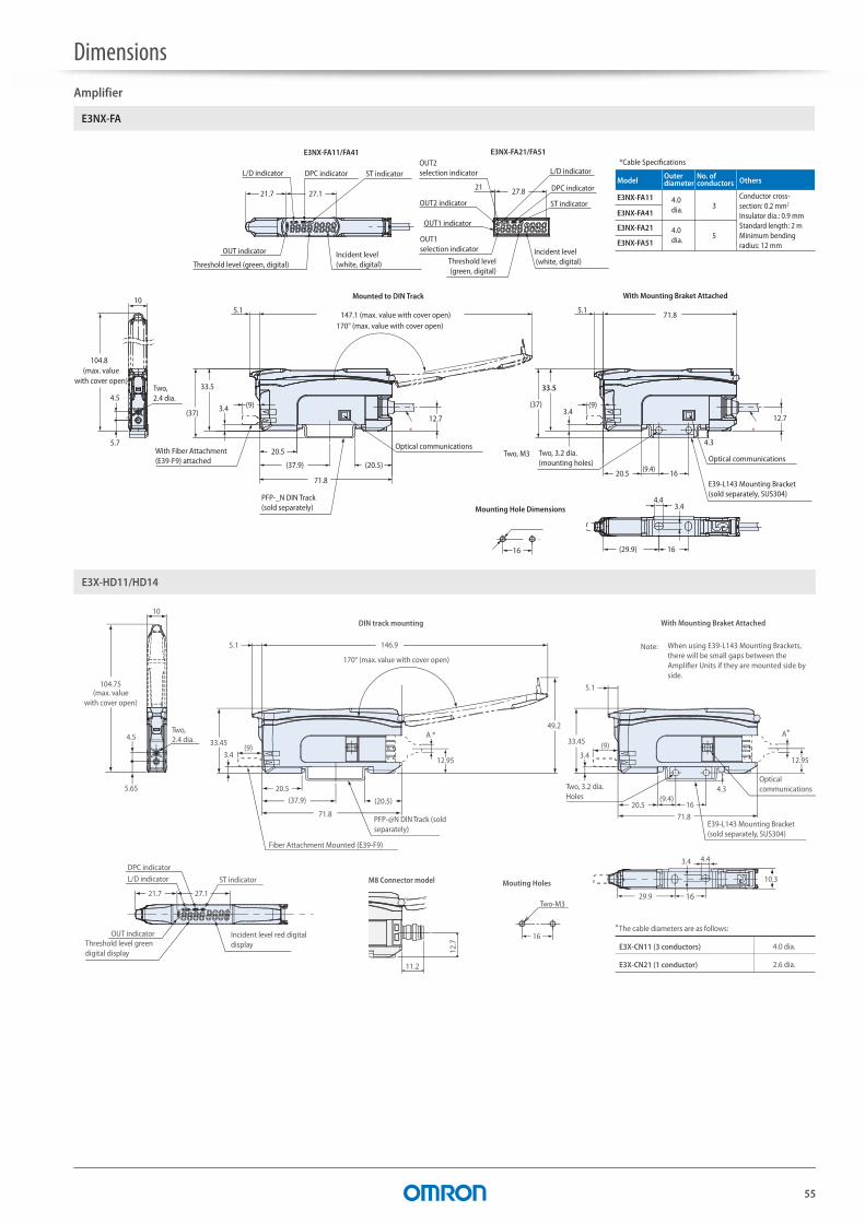
Dimensions
55
Amplifier
Two, M3
(37)
33.5
3.4 (9)
3.44.4
(37)
33.5
3.4(9)
5.1
71.8
E3NX-FA11/FA41
21
Incident level (white, digital)Threshold level
(green, digital)
OUT1 indicator
L/D indicator
DPC indicator
ST indicatorOUT2 indicator
E3NX-FA21/FA51OUT2 selection indicator
OUT1 selection indicator
104.8(max. value
with cover open)
10
5.7
4.5Two, 2.4 dia.
16
170° (max. value with cover open)147.1 (max. value with cover open)
27.8
L/D indicator DPC indicator ST indicator
Incident level (white, digital)
OUT indicator
Threshold level (green, digital)
21.7 27.1
12.7
(20.5)
20.5
(37.9)
*
5.1
16
71.8
(29.9) 16
12.7
20.5 (9.4)
4.3 *
Mounting Hole Dimensions
With Mounting Braket AttachedMounted to DIN Track
E3NX-FA11
Model
4.0 dia. 3
Outerdiameter
No. of conductors
Conductor cross-section: 0.2 mm2
Insulator dia.: 0.9 mmStandard length: 2 mMinimum bending radius: 12 mm
Others
E3NX-FA41
E3NX-FA21 4.0 dia. 5
E3NX-FA51
*Cable Specifications
With Fiber Attachment (E39-F9) attached
Optical communications
PFP-_N DIN Track (sold separately)
Optical communications
E39-L143 Mounting Bracket(sold separately, SUS304)
Two, 3.2 dia. (mounting holes)
E3NX-FA
E3X-CN11 (3 conductors)
E3X-CN21 (1 conductor)
4.0 dia.
2.6 dia.
* The cable diameters are as follows:
A *
12.95
A *
Mouting Holes
5.1
71.820.5
33.45 (9)3.4
(9.4)16
1629.9
4.43.4
10.3
DPC indicator
ST indicator
27.121.7
L/D indicator
OUT indicator
Two,2.4 dia.
10
4.5
5.65
5.1
20.5
146.9
33.45
(37.9)
(9)3.4
(20.5)
170° (max. value with cover open)
49.2
71.8
16
Two-M3
12.95
Fiber Attachment Mounted (E39-F9)
4.3
104.75
Note: When using E39-L143 Mounting Brackets, there will be small gaps between the Amplifier Units if they are mounted side by side.
Incident level red digital displayThreshold level green
digital display
(max. value with cover open)
PFP-@N DIN Track (sold separately)
Optical communications
E39-L143 Mounting Bracket (sold separately, SUS304)
Two, 3.2 dia. Holes
M8 Connector model
11.2
12.7
E3X-HD11/HD14
DIN track mounting With Mounting Braket Attached
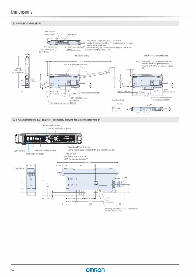
Dimensions
56
Mounting Holes
L/D indicator
OUT indicator
DPC indicator
ST indicator
Two,2.4 dia.
10
4.5
5.65
104.75
Fiber Attachment mounted (E39-F9)
5.1
(9)
(37.9) (20.5)71.8
12.67
20.5
3.4
Optical communications
146.9
170° (max. value with cover open)
49.2
33.45
16
Two-M3
(9.4)
1629.9
4.43.4
5.1
71.8
12.67
20.5
3.4(9)
16Two, 3.2 dia. Holes
33.45
10.3
4.3
Note: When using E39-L143 Mounting Brackets, there will be small gaps between the Amplifier Units if they are mounted side by side.
Vinyl-insulated round cable, 4 dia., 3 conductors (conductor cross-section: 0.2 mm², insulation diameter: 1.1 mm), standard cable length: 2 m Unbendable length at connection to the Amplifier Unit: 10 mm Minimum bending radius: 12 mm
Incident level red digital displayThreshold level green
digital display
(max. value with cover open)
PFP-_N DIN Track (sold separately)
Optical communications
E39-L143 Mounting Bracket (sold separately, SUS304)
E3X-HD6/HD8/HD14/HD44
DIN track mounting With Mounting Braket Attached
27.127.1
E3X-NA amplifiers (manual adjuster) - exemplary drawing for M8 connector version
Incident level indicatorsLock Button
Sensitivity Indicator8-turn sensitivity adjuster
Operation indicator
Operation Mode SelectorUse to switch between Light ON and Dark ON modes.
Timer switchON: Timer function is ON.OFF: Timer function is OFF.
12
8
10.7
Two, 2.4 dia.
4.3
9.9
3.43.9
33
Holes for
optical
communications
23.9
14.4
11.5 67.2
37
16
11
11.2
2.8 M8
40
Mounting bracket (E39-L148); Sold separatelyStainless steel (SUS304)
6.9
81.5
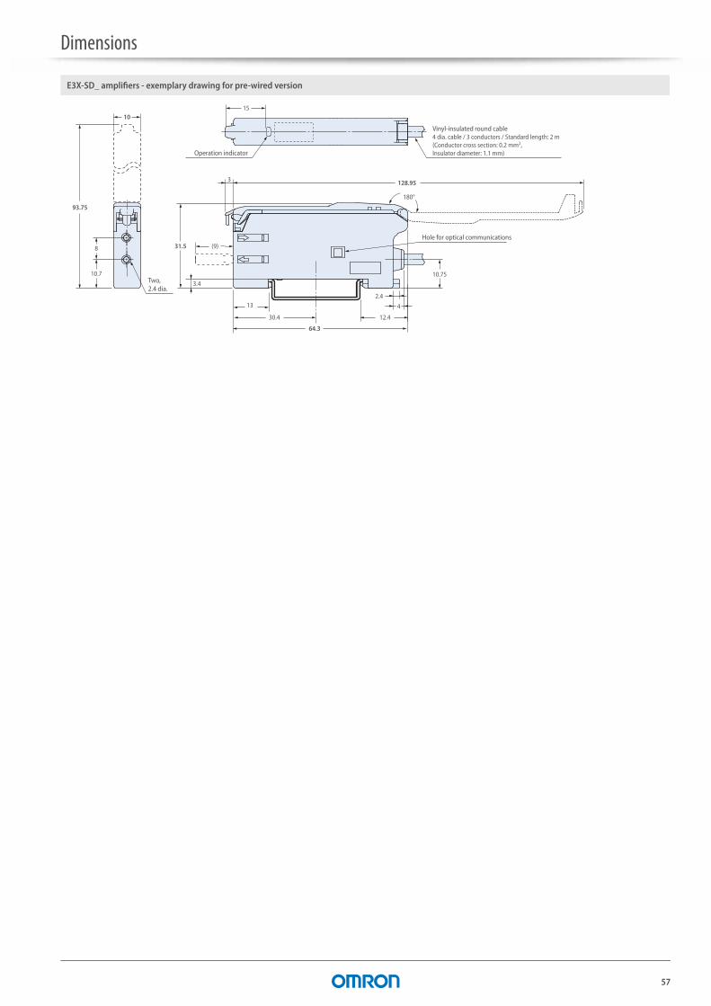
Dimensions
57
180°
8
10.7
3 128.95
2.4
4
10.75
(9)
3.4
31.5
1015
93.75
13
12.430.4
64.3
Operation indicator
Two, 2.4 dia.
Hole for optical communications
Vinyl-insulated round cable4 dia. cable / 3 conductors / Standard length: 2 m (Conductor cross section: 0.2 mm2, Insulator diameter: 1.1 mm)
E3X-SD_ amplifiers - exemplary drawing for pre-wired version
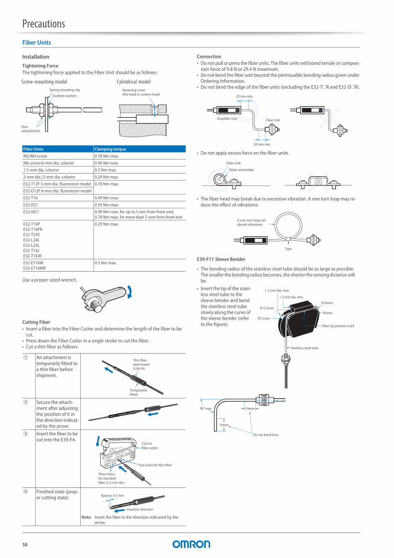
58
PrecautionsFiber Units
Installation
Tightening ForceThe tightening force applied to the Fiber Unit should be as follows:
Use a proper-sized wrench.
Cutting Fiber• Insert a fiber into the Fiber Cutter and determine the length of the fiber to be
cut.• Press down the Fiber Cutter in a single stroke to cut the fiber.• Cut a thin fiber as follows:
Connection• Do not pull or press the fiber units. The fiber units withstand tensile or compres-
sion force of 9.8 N or 29.4 N maximum.• Do not bend the fiber unit beyond the permissable bending radius given under
Ordering Information.• Do not bend the edge of the fiber units (excluding the E32-T#R and E32-D#R).
• Do not apply excess force on the fiber units.
• The fiber head may break due to excessive vibration. A one turn loop may re-duce the effect of vibrations:
E39-F11 Sleeve Bender
Fiber Units Clamping torque
M3/M4 screw 0.78 Nm max.
M6 screw/6-mm dia. column 0.98 Nm max.
1.5-mm dia. column 0.2 Nm max.
2-mm dia./3-mm dia. column 0.29 Nm max.
E32-T12F 5-mm dia. fluororesin model 0.78 Nm max.
E32-D12F 6-mm dia. fluororesin model
E32-T16 0.49 Nm max.
E32-R21 0.59 Nm max.
E32-M21 0.49 Nm max. for up to 5 mm from front end, 0.78 Nm max. for more than 5 mm from front end
E32-T16PE32-T16PRE32-T24SE32-L24LE32-L25LE32-T16JE32-T16JR
0.29 Nm max.
E32-ET16WE32-ET16WR
0.3 Nm max.
A An attachment is temporarily fitted to a thin fiber before shipment.
B Secure the attach-ment after adjusting the position of it in the direction indicat-ed by the arrow.
C Insert the fiber to be cut into the E39-F4.
D Finished state (prop-er cutting state)
Note: Insert the fiber in the direction indicated by the arrow.
Toothed washers
Spring mounting clip
Nuts(attachment)
Retaining screw(flat head or sunken head)
Cylindrical modelScrew-mounting model
Temporarilyfitted
Thin fiberattachment(E39-F9)
Three holesfor standardfiber (2.2-mm dia.)
Two holes for thin fiber
E39-F4fiber cutter
Approx. 0.5 mm
Insertion direction
• The bending radius of the stainless steel tube should be as large as possible. The smaller the bending radius becomes, the shorter the sensing distance will be.
• Insert the tip of the stain-less steel tube to the sleeve bender and bend the stainless steel tube slowly along the curve of the sleeve bender (refer to the figure).
Amplifier Unit Fiber Unit
20 mm min.
20 mm min.
Fiber Unit
Nylon wireholder
Tape
A one-turn loop can absorb vibrations.
1.2-mm dia. max
R12.5mm
R7.5mm
1.3-mm dia. min.
R10mm
Fiber tip position mark
Stainless steel tube
R5mm
90° max.
10mm
10mm
Do not bend here.
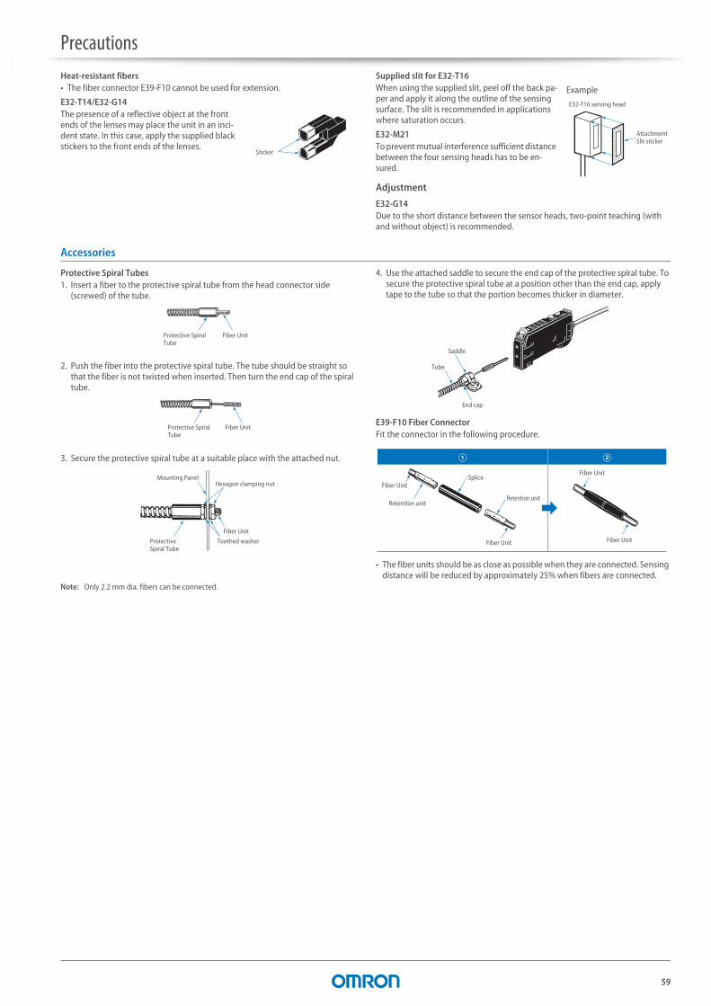
Precautions
59
Heat-resistant fibers• The fiber connector E39-F10 cannot be used for extension.
E32-T14/E32-G14The presence of a reflective object at the front ends of the lenses may place the unit in an inci-dent state. In this case, apply the supplied black stickers to the front ends of the lenses.
Supplied slit for E32-T16When using the supplied slit, peel off the back pa-per and apply it along the outline of the sensing surface. The slit is recommended in applications where saturation occurs.
E32-M21To prevent mutual interference sufficient distance between the four sensing heads has to be en-sured.
Adjustment
E32-G14Due to the short distance between the sensor heads, two-point teaching (with and without object) is recommended.
Accessories
Protective Spiral Tubes1. Insert a fiber to the protective spiral tube from the head connector side
(screwed) of the tube.
2. Push the fiber into the protective spiral tube. The tube should be straight so that the fiber is not twisted when inserted. Then turn the end cap of the spiral tube.
3. Secure the protective spiral tube at a suitable place with the attached nut.
4. Use the attached saddle to secure the end cap of the protective spiral tube. To secure the protective spiral tube at a position other than the end cap, apply tape to the tube so that the portion becomes thicker in diameter.
E39-F10 Fiber ConnectorFit the connector in the following procedure.
• The fiber units should be as close as possible when they are connected. Sensing distance will be reduced by approximately 25% when fibers are connected.
Note: Only 2.2 mm dia. fibers can be connected.
Sticker
Attachment Slit sticker
E32-T16 sensing head
Example
Protective Spiral Tube
Fiber Unit
Protective Spiral Tube
Fiber Unit
Protective Spiral Tube
Toothed washer
Fiber Unit
Hexagon clamping nutMounting Panel
End cap
Tube
Saddle
Retention unit
Fiber UnitSplice
Retention unit
Fiber Unit Fiber Unit
Fiber Unit
A B
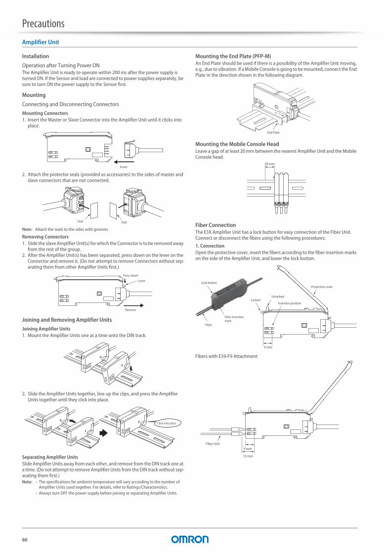
Precautions
60
Amplifier Unit
Installation
Operation after Turning Power ONThe Amplifier Unit is ready to operate within 200 ms after the power supply is turned ON. If the Sensor and load are connected to power supplies separately, be sure to turn ON the power supply to the Sensor first.
Mounting
Connecting and Disconnecting Connectors
Mounting Connectors1. Insert the Master or Slave Connector into the Amplifier Unit until it clicks into
place.
2. Attach the protector seals (provided as accessories) to the sides of master and slave connectors that are not connected.
Note: Attach the seals to the sides with grooves
Removing Connectors1. Slide the slave Amplifier Unit(s) for which the Connector is to be removed away
from the rest of the group.2. After the Amplifier Unit(s) has been separated, press down on the lever on the
Connector and remove it. (Do not attempt to remove Connectors without sep-arating them from other Amplifier Units first.)
Joining and Removing Amplifier Units
Joining Amplifier Units1. Mount the Amplifier Units one at a time onto the DIN track.
2. Slide the Amplifier Units together, line up the clips, and press the Amplifier Units together until they click into place.
Separating Amplifier UnitsSlide Amplifier Units away from each other, and remove from the DIN track one at a time. (Do not attempt to remove Amplifier Units from the DIN track without sep-arating them first.)Note: - The specifications for ambient temperature will vary according to the number of
Amplifier Units used together. For details, refer to Ratings/Characteristics.- Always turn OFF the power supply before joining or separating Amplifier Units.
Mounting the End Plate (PFP-M)An End Plate should be used if there is a possibility of the Amplifier Unit moving, e.g., due to vibration. If a Mobile Console is going to be mounted, connect the End Plate in the direction shown in the following diagram.
Mounting the Mobile Console HeadLeave a gap of at least 20 mm between the nearest Amplifier Unit and the Mobile Console head.
Fiber ConnectionThe E3X Amplifier Unit has a lock button for easy connection of the Fiber Unit. Connect or disconnect the fibers using the following procedures:
1. ConnectionOpen the protective cover, insert the fibers according to the fiber insertion marks on the side of the Amplifier Unit, and lower the lock button.
Fibers with E39-F9 Attachment
Insert
Seal Seal
Press down
Remove
Lever
Click into place
End Plate
20 mm
Lock button
Fiber
Fiber insertion mark
LockedUnlocked
Insertion position
Protective cover
9 mm
Fiber Unit9 mm
13 mm
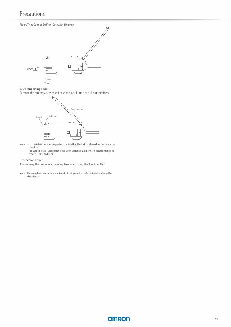
Precautions
61
Fibers That Cannot Be Free-Cut (with Sleeves)
2. Disconnecting FibersRemove the protective cover and raise the lock button to pull out the fibers.
Note: - To maintain the fiber properties, confirm that the lock is released before removing the fibers.
- Be sure to lock or unlock the lock button within an ambient temperature range be-tween 10C and 40C.
Protective CoverAlways keep the protective cover in place when using the Amplifier Unit.
Note: For complete precautions and installation instructions refer to individual amplifier datasheets.
9 mm
13 mm
Locked Unlocked
Protective cover

62
Product list
Order code Group Page
E32-A03 2M Precision detection 21
Special application 24
E32-A03-1 2M Square shape 10
E32-A04 2M Miniature 12
Precision detection 21
Special application 24
E32-A04-1 2M Square shape 10
E32-A09 2M Precision detection 21
Special application 24
E32-A09H 2M Heat resistant 17
E32-A09H2 2M Heat resistant 17
E32-A10 2M Special application 24
E32-C11N 2M Precision detection 21
E32-C21N 2M Precision detection 21
E32-C31 2M Precision detection 21
Special application 24
E32-C31N 2M Precision detection 21
E32-C41 1M Precision detection 21
Precision detection 21
E32-CC200 2M Precision detection 21
Special application 24
E32-D11 2M Robot applications 20
E32-D11L 2M Longer distance 14
E32-D11N 2M Standard cylindrical 8
E32-D11R 2M Standard cylindrical 8
E32-D11U 2M Chemical resistant 16
E32-D12 2M Longer distance 14
E32-D12F Chemical resistant 16
E32-D14F 2M Chemical resistant 16
E32-D14L 2M Standard cylindrical 8
E32-D14LR 2M Standard cylindrical 8
E32-D15X 2M Square shape 10
E32-D15XB 2M Robot applications 20
E32-D15XR 2M Square shape 10
E32-D15Y 2M Square shape 10
E32-D15YR 2M Square shape 10
E32-D15Z 2M Square shape 10
E32-D16 2M Longer distance 14
E32-D21 2M Robot applications 20
E32-D211 2M Standard cylindrical 8
E32-D211R 2M Standard cylindrical 8
E32-D21B 2M Robot applications 20
E32-D21L 2M Longer distance 14
E32-D21N 2M Longer distance 14
E32-D21R 2M Standard cylindrical 8
E32-D22 2M Miniature 12
E32-D22B 2M Miniature 12
Robot applications 20
E32-D22R 2M Miniature 12
E32-D24 Miniature 12
E32-D24R 2M Miniature 12
E32-D32 2M Miniature 12
Precision detection 21
E32-D32L 2M Precision detection 21
E32-D32R 2M Miniature 12
E32-D33 2M Miniature 12
E32-D331 2M Miniature 12
E32-D36P1 2M Area monitoring 23
E32-D36T 2M Special application 24
E32-D51 2M Heat resistant 17
E32-D51R 2M Heat resistant 17
E32-D61/ D61-S 2M Heat resistant 17
E32-D73/ D73-S 2M Heat resistant 17
E32-D81R/ D81R-S 2M Heat resistant 17
E32-D82F1 4M Special application 24
E32-DC200 2M Standard cylindrical 8
E32-DC200B 2M Miniature 12
E32-DC200BR Miniature 12
E32-DC200E 2M Standard cylindrical 8
E32-DC200F Miniature 12
E32-DC200FR Miniature 12
E32-E01 100M Accessories 26
E32-E01R 100M Accessories 26
E32-E02 100M Accessories 26
E32-E02R 100M Accessories 26
E32-E05 100M Accessories 26
E32-ED11F 2M Chemical resistant 16
E32-EDS24R 2M Square shape 10
E32-EL24-1 2M Precision detection 21
Special application 24
E32-ET15YR Square shape 10
E32-ET15ZR Square shape 10
E32-ET16WR-1 2M Area monitoring 23
E32-ET16WR-2 2M Area monitoring 23
E32-ETC220 2M Standard cylindrical 8
E32-ETS10R 2M Square shape 10
E32-ETS14R 2M Square shape 10
E32-G14 Special application 24
E32-L11FS Special application 24
E32-L15 Mark detection 37
E32-L16-N 2M Precision detection 21
E32-L24L Precision detection 21
E32-L25 Precision detection 21
E32-L25L Precision detection 21
Special application 24
E32-L64 Heat resistant 17
Special application 24
E32-L66 2M Heat resistant 17
Special application 24
E32-LD11 Longer distance 14
E32-LD11N 2M Longer distance 14
E32-LD11R Longer distance 14
E32-LR11NP 2M Longer distance 14
E32-LT11 Longer distance 14
E32-LT11N 2M Longer distance 14
E32-LT11R Longer distance 14
E32-M21 Area monitoring 23
E32-R16 2M Longer distance 14
E32-R21 Standard cylindrical 8
E32-T11 2M Robot applications 20
E32-T11L 2M Longer distance 14
E32-T11N 2M Standard cylindrical 8
E32-T11R 2M Standard cylindrical 8
E32-T11U 2M Chemical resistant 16
E32-T12 2M Miniature 12
E32-T12B Robot applications 20
E32-T12F Chemical resistant 16
E32-T12L 2M Longer distance 14
E32-T12R 2M Miniature 12
E32-T14 2M Longer distance 14
E32-T14F 2M Chemical resistant 16
E32-T14L 2M Miniature 12
E32-T14LR 2M Miniature 12
E32-T15X 2M Square shape 10
E32-T15XB 2M Robot applications 20
E32-T15Y 2M Square shape 10
E32-T15YR 2M Square shape 10
E32-T15Z 2M Square shape 10
E32-T16 Area monitoring 23
E32-T16J 2M Area monitoring 23
E32-T16JR 2M Area monitoring 23
E32-T16P Area monitoring 23
E32-T16PR 2M Area monitoring 23
E32-T16W 2M Area monitoring 23
E32-T16WR 2M Area monitoring 23
E32-T17L Longer distance 14
E32-T21 2M Robot applications 20
E32-T21R 2M Standard cylindrical 8
Order code Group Page
E32-T22 2M Miniature 12
E32-T221B Robot applications 20
E32-T222 2M Miniature 12
E32-T222R 2M Miniature 12
E32-T22B Robot applications 20
E32-T22L 2M Longer distance 14
E32-T22R 2M Miniature 12
E32-T22S Precision detection 21
Special application 24
E32-T24 Miniature 12
E32-T24R 2M Miniature 12
E32-T24S Special application 24
E32-T51 2M Heat resistant 17
E32-T51F 2M Chemical resistant 16
E32-T51R 2M Heat resistant 17
E32-T51V 1M Vacuum resistant 19
E32-T54 2M Heat resistant 17
E32-T54V 1M Vacuum resistant 19
E32-T61-S 2M Heat resistant 17
E32-T81F-S 2M Chemical resistant 16
E32-T81R-S 2M Heat resistant 17
E32-T84S-S 2M Heat resistant 17
E32-T84SV 1M Vacuum resistant 19
E32-TC200 2M Standard cylindrical 8
E32-TC200A 2M Longer distance 14
E32-TC200B Miniature 12
E32-TC200BR Miniature 12
E32-TC200E 2M Standard cylindrical 8
E32-TC200F Miniature 12
E32-TC200FR Miniature 12
E39-EF1-37 Accessories 26
E39-EF51 Accessories 26
E39-F1 Accessories 26
E39-F10 Accessories 26
E39-F11 Accessories 26
E39-F13 Accessories 26
E39-F14 Accessories 26
E39-F15 Accessories 26
E39-F16 Accessories 26
E39-F18 Accessories 26
E39-F1V Accessories 26
E39-F2 Accessories 26
E39-F32A Accessories 26
E39-F32B Accessories 26
E39-F32C Accessories 26
E39-F32D Accessories 26
E39-F3A Accessories 26
E39-F3A-5 Accessories 26
E39-F3B Accessories 26
E39-F4 Accessories 26
E39-F9 Accessories 26
E39-R1S Accessories 26
E39-R3 Accessories 26
E3NX-FA Advanced amplifiers 32
E3X-CN21 Accessories 26
E3X-CN21-M1J Accessories 26
E3X-CN21-M3J-2 Accessories 26
E3X-DAC_-S Advanced amplifiers 37
E3X-DAH-S Advanced amplifiers 39
E3X-HD Easy usage amplifiers 27
E3X-MDA_ Advanced amplifiers 35
E3X-NA Easy usage amplifiers 31
E3X-NA_F Advanced amplifiers 36
E3X-SD Easy usage amplifiers 30
Order code Group Page
63
READ AND UNDERSTAND THIS DOCUMENT
Please read and understand this document before using the products. Please consult your OMRON representative if you have any questions or comments.
WARRANTY
OMRON’s exclusive warranty is that the products are free from defects in materials and work-manship for a period of one year (or other period if specified) from date of sale by OMRON.
OMRON MAKES NO WARRANTY OR REPRESENTATION, EXPRESS OR IMPLIED, REGARDING NON-IN-FRINGEMENT, MERCHANTABILITY, OR FITNESS FOR PARTICULAR PURPOSE OF THE PRODUCTS. ANY BUYER OR USER ACKNOWLEDGES THAT THE BUYER OR USER ALONE HAS DETERMINED THAT THE PRODUCTS WILL SUITABLY MEET THE REQUIREMENTS OF THEIR INTENDED USE. OMRON DIS-CLAIMS ALL OTHER WARRANTIES, EXPRESS OR IMPLIED.
LIMITATIONS OF LIABILITY
OMRON SHALL NOT BE RESPONSIBLE FOR SPECIAL, INDIRECT, OR CONSEQUENTIAL DAMAGES, LOSS OF PROFITS OR COMMERCIAL LOSS IN ANY WAY CONNECTED WITH THE PRODUCTS, WHETHER SUCH CLAIM IS BASED ON CONTRACT, WARRANTY, NEGLIGENCE, OR STRICT LIABILITY.
In no event shall responsibility of OMRON for any act exceed the individual price of the product on which liability is asserted.
IN NO EVENT SHALL OMRON BE RESPONSIBLE FOR WARRANTY, REPAIR, OR OTHER CLAIMS RE-GARDING THE PRODUCTS UNLESS OMRON’S ANALYSIS CONFIRMS THAT THE PRODUCTS WERE PROPERLY HANDLED, STORED, INSTALLED, AND MAINTAINED AND NOT SUBJECT TO CONTAMINA-TION, ABUSE, MISUSE, OR INAPPROPRIATE MODIFICATION OR REPAIR.
SUITABILITY FOR USE
THE PRODUCTS CONTAINED IN THIS DOCUMENT ARE NOT SAFETY RATED. THEY ARE NOT DESIGNED OR RATED FOR ENSURING SAFETY OF PERSONS, AND SHOULD NOT BE RELIED UPON AS A SAFETY COMPONENT OR PROTECTIVE DEVICE FOR SUCH PURPOSES. Please refer to separate catalogs for OMRON's safety rated products.
OMRON shall not be responsible for conformity with any standards, codes, or regulations that apply to the combination of products in the customer’s application or use of the product.
At the customer’s request, OMRON will provide applicable third party certification documents identifying ratings and limitations of use that apply to the products. This information by itself is not sufficient for a complete determination of the suitability of the products in combination with the end product, machine, system, or other application or use.
The following are some examples of applications for which particular attention must be given. This is not intended to be an exhaustive list of all possible uses of the products, nor is it intended to imply that the uses listed may be suitable for the products:
• Outdoor use, uses involving potential chemical contamination or electrical interference, or conditions or uses not described in this document.
• Nuclear energy control systems, combustion systems, railroad systems, aviation systems, medical equipment, amusement machines, vehicles, safety equipment, and installations subject to separate industry or government regulations.
• Systems, machines, and equipment that could present a risk to life or property.
Please know and observe all prohibitions of use applicable to the products.
NEVER USE THE PRODUCTS FOR AN APPLICATION INVOLVING SERIOUS RISK TO LIFE OR PROPERTY WITHOUT ENSURING THAT THE SYSTEM AS A WHOLE HAS BEEN DESIGNED TO ADDRESS THE RISKS, AND THAT THE OMRON PRODUCT IS PROPERLY RATED AND INSTALLED FOR THE INTENDED USE WITHIN THE OVERALL EQUIPMENT OR SYSTEM.
PERFORMANCE DATA
Performance data given in this document is provided as a guide for the user in determining suit-ability and does not constitute a warranty. It may represent the result of OMRON’s test condi-tions, and the users must correlate it to actual application requirements. Actual performance is subject to the OMRON Warranty and Limitations of Liability.
CHANGE IN SPECIFICATIONS
Product specifications and accessories may be changed at any time based on improvements and other reasons.
It is our practice to change model numbers when published ratings or features are changed, or when significant construction changes are made. However, some specifications of the product may be changed without any notice. When in doubt, special model numbers may be assigned to fix or establish key specifications for your application on your request. Please consult with your OMRON representative at any time to confirm actual specifications of purchased products.
DIMENSIONS AND WEIGHTS
Dimensions and weights are nominal and are not to be used for manufacturing purposes, even when tolerances are shown.
ERRORS AND OMISSIONS
The information in this document has been carefully checked and is believed to be accurate; however, no responsibility is assumed for clerical, typographical, or proofreading errors, or omissions.
PROGRAMMABLE PRODUCTS
OMRON shall not be responsible for the user’s programming of a programmable product, or any consequence thereof.
COPYRIGHT AND COPY PERMISSION
This document shall not be copied for sales or promotions without permission.
This document is protected by copyright and is intended solely for use in conjunction with the product. Please notify us before copying or reproducing this document in any manner, for any other purpose. If copying or transmitting this document to another, please copy or transmit it in its entirety.
Austria Tel: +43 (0) 2236 377 800 www.industrial.omron.at
Belgium Tel: +32 (0) 2 466 24 80 www.industrial.omron.be
Czech Republic Tel: +420 234 602 602 www.industrial.omron.cz
Denmark Tel: +45 43 44 00 11 www.industrial.omron.dk
Finland Tel: +358 (0) 207 464 200www.industrial.omron.fi
France Tel: +33 (0) 1 56 63 70 00www.industrial.omron.fr
Germany Tel: +49 (0) 2173 680 00 www.industrial.omron.de
Hungary Tel: +36 1 399 30 50 www.industrial.omron.hu
Italy Tel: +39 02 326 81 www.industrial.omron.it
Netherlands Tel: +31 (0) 23 568 11 00 www.industrial.omron.nl
Norway Tel: +47 (0) 22 65 75 00 www.industrial.omron.no
Poland Tel: +48 (0) 22 645 78 60 www.industrial.omron.pl
Portugal Tel: +351 21 942 94 00 www.industrial.omron.pt
Russia Tel: +7 495 648 94 50 www.industrial.omron.ru
South-Africa Tel: +27 (0)11 579 2600 www.industrial.omron.co.za
Spain Tel: +34 913 777 900 www.industrial.omron.es
Sweden Tel: +46 (0) 8 632 35 00 www.industrial.omron.se
Switzerland Tel: +41 (0) 41 748 13 13 www.industrial.omron.ch
Turkey Tel: +90 216 474 00 40 www.industrial.omron.com.tr
United Kingdom Tel: +44 (0) 870 752 08 61 www.industrial.omron.co.uk
More Omron representativeswww.industrial.omron.eu
Control Systems • Programmable logic controllers • Human-machine interfaces • Remote I/O
Motion & Drives • Motion controllers • Servo systems • Inverters
Control Components • Temperature controllers • Power supplies • Timers • Counters • Programmable relays • Digital panel indicators • Electromechanical relays • Monitoring products • Solid-state relays • Limit switches • Pushbutton switches • Low voltage switch gear
Sensing & Safety • Photoelectric sensors • Inductive sensors • Capacitive & pressure sensors • Cable connectors • Displacement & width-measuring sensors • Vision systems • Safety networks • Safety sensors • Safety units/relay units • Safety door/guard lock switches
Authorised Distributor:
Although we strive for perfection, Omron Europe BV and/or its subsidiary and affiliated companies do not warrant or make any representations regarding the correctness or completeness of the information described in this document. We reserve the right to make any changes at any time without prior notice.
OMRON EUROPE B.V. Wegalaan 67-69, NL-2132 JD, Hoofddorp, The Netherlands. Tel: +31 (0) 23 568 13 00 Fax: +31 (0) 23 568 13 88 www.industrial.omron.eu
E56E-EN-07+FiberGuide


