12
CATALOG 1900 | FEBRUARY 2019 WWW.TCF.COM INDUSTRIAL PROCESS AND COMMERCIAL VENTILATION SYSTEMS FIBERGLASS CENTRIFUGAL FANS Model BAFF
CATALOG 1900 | FEBRUARY 2019 WWW.TCF.COM
INDUSTRIAL PROCESS AND
COMMERCIAL VENTILATION SYSTEMS
FIBERGLASS CENTRIFUGAL FANSModel BAFF
TWIN CITY FAN - CATALOG 19002
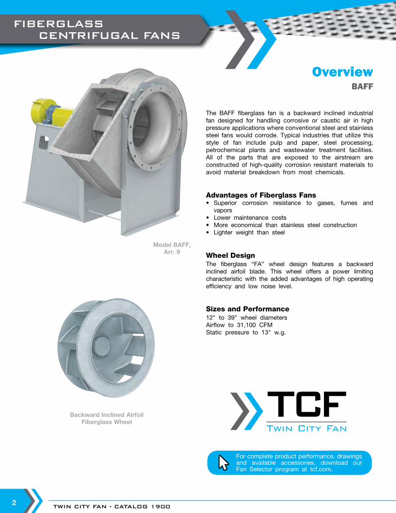
Model BAFF,Arr. 9
The BAFF fiberglass fan is a backward inclined industrial fan designed for handling corrosive or caustic air in high pressure applications where conventional steel and stainless steel fans would corrode. Typical industries that utilize this style of fan include pulp and paper, steel processing, petrochemical plants and wastewater treatment facilities. All of the parts that are exposed to the airstream are constructed of high-quality corrosion resistant materials to avoid material breakdown from most chemicals.
Advantages of Fiberglass Fans• Superior corrosion resistance to gases, fumes and
vapors• Lower maintenance costs• More economical than stainless steel construction• Lighter weight than steel
Wheel DesignThe fiberglass “FA” wheel design features a backward inclined airfoil blade. This wheel offers a power limiting characteristic with the added advantages of high operating efficiency and low noise level.
Sizes and Performance12" to 39" wheel diametersAirflow to 31,100 CFMStatic pressure to 13" w.g.
Backward Inclined AirfoilFiberglass Wheel
FIBERGLASS CENTRIFUGAL FANS
OverviewBAFF
Twin City Fan
Twin City Fan
For complete product performance, drawings and available accessories, download our Fan Selector program at tcf.com.
WWW.TCF.COM 3
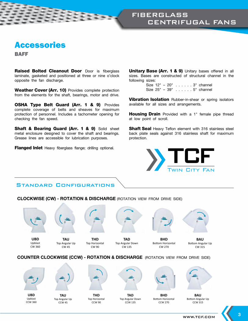
Standard Configurations
THDTop Horizontal
CW 90
TADTop Angular Down
CW 135
UBD UpblastCW 360
TAUTop Angular Up
CW 45
BHDBottom Horizontal
CW 270
BAUBottom Angular Up
CW 315
CLOCKWISE (CW) - ROTATION & DISCHARGE (ROTATION VIEW FROM DRIVE SIDE)
COUNTER CLOCKWISE (CCW) - ROTATION & DISCHARGE (ROTATION VIEW FROM DRIVE SIDE)
THDTop Horizontal
CCW 90
TADTop Angular Down
CCW 135
UBD Upblast
CCW 360
TAUTop Angular Up
CCW 45
BHDBottom Horizontal
CCW 270
BAUBottom Angular Up
CCW 315
Raised Bolted Cleanout Door Door is fiberglass laminate, gasketed and positioned at three or nine o’clock opposite the fan discharge.
Weather Cover (Arr. 10) Provides complete protection from the elements for the shaft, bearings, motor and drive.
OSHA Type Belt Guard (Arr. 1 & 9) Provides complete coverage of belts and sheaves for maximum protection of personnel. Includes a tachometer opening for checking the fan speed.
Shaft & Bearing Guard (Arr. 1 & 9) Solid sheet metal enclosure designed to cover the shaft and bearings. Grease lines are accessible for lubrication purposes.
Flanged Inlet Heavy fiberglass flange; drilling optional.
Unitary Base (Arr. 1 & 9) Unitary bases offered in all sizes. Bases are constructed of structural channel in the following sizes: Size 12" – 20" . . . . . . 3" channel Size 25" – 39" . . . . . . 5" channel
Vibration Isolation Rubber-in-shear or spring isolators available for all sizes and arrangements.
Housing Drain Provided with a 1" female pipe thread at low point of scroll.
Shaft Seal Heavy Teflon element with 316 stainless steel back plate seals against 316 stainless shaft for maximum protection.
FIBERGLASS CENTRIFUGAL FANS
AccessoriesBAFF
Twin City Fan
Twin City Fan
TWIN CITY FAN - CATALOG 19004
All-Welded Steel BaseArrangements 9 and 10 are provided with a slide rail motor base for ease in adjusting belt tension. All steel parts are finished with an air dry epoxy paint.
Flanged OutletIntegral flanged outlet is furnished as standard; drilling is optional.
RotationClockwise rotation is standard, counter-clockwise rotation is available as an option.
Arrangements & SizesSix fan sizes, 12" through 39", are available in arrangements 1, 9 and 10.
Product FinishAll fiberglass parts are coated inside and outside with resin (with UV inhibitor), approximately 10 mils in thickness, to seal and provide protection from ultraviolet light. This results in a smooth, high gloss finish. All steel parts are finished with an air dry epoxy paint.
Corrosion ResistantAll airstream parts of fiberglass reinforced polyester with resistance to most chemicals. The wheel is constructed of vinyl ester fiberglass resin as standard. Standard construction meets ASTM 84 flame spread rating of 25 or less. Housing construction of vinyl ester is available as an option. See “Optional Construction” below and the “Corrosion Resistance Guide” on page 7.
Non-Overloading Power CharacteristicPrevents motor overload under variable operating conditions. The aluminum hub and carbon steel shaft assembly are bolted to a fiberglass wheel and completely coated with fiberglass laminate for maximum corrosion protection.
Aluminum HubHub and carbon steel shaft assembly bolted to a fiberglass wheel and completely coated with fiberglass laminate for maximum corrosion protection.
Shaft Hole ClosureThin Teflon membrane secured with a 316 SS steel plate to minimize housing leakage.
Inlet ConnectionSlip-type connection is standard.
Special Fiberglass MaterialsPlease contact the factory to ensure a suitable material is selected for the specific application.
• Vinyl Ester — Provides increased corrosion resistance to stronger acids, chlorine and oxidizing agents. For use in industrial applications such as chemical and water treatment plants, and commercial applications where urban or salt air corrosion exists. The wheel is constructed of vinyl ester fiberglass resin as standard. Housing construction of vinyl ester is available as an option.
• Surface Veil — Produces a smooth reinforced final surface with greater corrosion resistance and contains a UV inhibitor to provide protection from ultraviolet rays.
• Fire-Retardant Resin — Reduces the resin’s tendency to burn by achieving a flame-spread rating of 25 or less.
Spark Resistant ConstructionSpark resistant construction for fiberglass fans is recommended when the fan is handling explosive fumes. Although fiberglass is a non-sparking material, it can build and retain a static charge that can be potentially hazardous. With spark resistant construction, the fan is statically grounded by graphite impregnation to reduce a static charge buildup.
CONSTRUCTION FEATURES
Twin City Fan
Twin City Fan
Optional Construction
WWW.TCF.COM 5
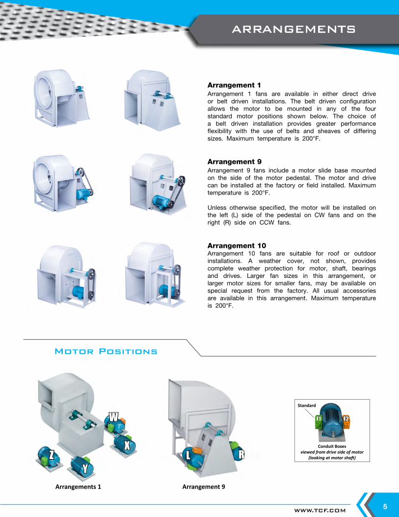
Arrangement 1Arrangement 1 fans are available in either direct drive or belt driven installations. The belt driven configuration allows the motor to be mounted in any of the four standard motor positions shown below. The choice of a belt driven installation provides greater performance flexibility with the use of belts and sheaves of differing sizes. Maximum temperature is 200°F.
Arrangement 9Arrangement 9 fans include a motor slide base mounted on the side of the motor pedestal. The motor and drive can be installed at the factory or field installed. Maximum temperature is 200°F.
Unless otherwise specified, the motor will be installed on the left (L) side of the pedestal on CW fans and on the right (R) side on CCW fans.
Arrangement 10Arrangement 10 fans are suitable for roof or outdoor installations. A weather cover, not shown, provides complete weather protection for motor, shaft, bearings and drives. Larger fan sizes in this arrangement, or larger motor sizes for smaller fans, may be available on special request from the factory. All usual accessories are available in this arrangement. Maximum temperature is 200°F.
ARRANGEMENTS
X
W
YZ
Arrangements 1
RL
Arrangement 9
F1 F2
Conduit Boxesviewed from drive side of motor
(looking at motor shaft)
Standard
Motor Positions
TWIN CITY FAN - CATALOG 4156
PERFORMANCE CORRECTIONFOR TEMPERATURE & ALTITUDE
Table 2. Maximum Safe Wheel Speed at 70°F
Table 3. Maximum Safe Speed Temperature Factors
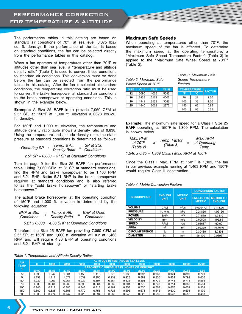
The performance tables in this catalog are based on standard air conditions of 70°F at sea level (0.075 lbs./cu. ft. density). If the performance of the fan is based on standard conditions, the fan can be selected directly from the performance tables in this catalog.
When a fan operates at temperatures other than 70°F or altitudes other than sea level, a “temperature and altitude density ratio” (Table 1) is used to convert these conditions to standard air conditions. This conversion must be done before the fan can be selected from the performance tables in this catalog. After the fan is selected at standard conditions, the temperature correction ratio must be used to convert the brake horsepower at standard air conditions to the brake horsepower at operating conditions. This is shown in the example below.
Example: A Size 25 BAFF is to provide 7,060 CFM at 2.5" SP, at 150°F at 1,000 ft. elevation (0.0628 lbs./cu. ft. density).
For 150°F and 1,000 ft. elevation, the temperature and altitude density ratio table shows a density ratio of 0.838. Using the temperature and altitude density ratio, the static pressure at standard conditions is determined as follows:
Temp. & Alt. SP at Std. Operating SP ÷ Density Ratio = Conditions
2.5" SP ÷ 0.838 = 3" SP at Standard Conditions
Turn to page 9 for the Size 25 BAFF fan performance table. Using 7,060 CFM at 3" SP at standard conditions, find the RPM and brake horsepower to be 1,463 RPM and 5.21 BHP. Note: 5.21 BHP is the brake horsepower required at standard conditions and is also referred to as the “cold brake horsepower” or “starting brake horsepower.”
The actual brake horsepower at the operating condition of 150°F and 1,000 ft. elevation is determined by the following equation:
BHP at Std. Temp. & Alt. BHP at Oper. Conditions x Density Ratio = Conditions
5.21 x 0.838 = 4.36 BHP at Operating Conditions
Therefore, the Size 25 BAFF fan providing 7,060 CFM at 2.5" SP, at 150°F and 1,000 ft. elevation will run at 1,463 RPM and will require 4.36 BHP at operating conditions and 5.21 BHP at starting.
Maximum Safe SpeedsWhen operating at temperatures other than 70°F, the maximum speed of the fan is affected. To determine the maximum speed at the operating temperature, a “Maximum Safe Speed Temperature Factor” (Table 3) is applied to the “Maximum Safe Wheel Speed at 70°F” (Table 2).
Table 1. Temperature and Altitude Density Ratios
Table 4. Metric Conversion Factors
Example: The maximum safe speed for a Class I Size 25 BAFF operating at 150°F is 1,309 RPM. The calculation is shown below.
Max. RPM Temp. Factor Max. RPM at 70°F x (Table 3) = at Operating (Table 2) Temp.
1,540 x 0.85 = 1,309 Class I Max. RPM at 150°F
Since the Class I Max. RPM at 150°F is 1,309, the fan in our previous example running at 1,463 RPM and 150°F would require Class II construction.
DESCRIPTIONENGLISH
UNITMETRIC
UNIT
CONVERSION FACTOR
ENGLISH TOMETRIC
METRIC TOENGLISH
VOLUME CFM m3/s 0.000472 2118.90PRESSURE in. w.g. kPa 0.24866 4.02156POWER BHP kW 0.74570 1.3410VELOCITY fpm m/s 0.00508 196.85SPEED RPM rps 0.01667 60.00AREA ft2 m2 0.09290 10.7640CIRCUMFERENCE ft m 0.30480 3.2808DIAMETER in. mm 25.400 0.03937
AIR TEMP
°F
ALTITUDE IN FEET ABOVE SEA LEVEL0 1000 2000 3000 4000 5000 6000 7000 8000 9000 10000 15000
BAROMETRIC PRESSURE IN INCHES OF MERCURY29.92 28.86 27.82 26.82 25.84 24.90 23.98 23.09 22.22 21.39 20.58 16.89
–50 1.293 1.247 1.201 1.159 1.116 1.076 1.036 0.997 0.960 0.924 0.889 0.7290 1.152 1.111 1.071 1.032 0.995 0.959 0.923 0.889 0.856 0.824 0.792 0.65050 1.039 1.003 0.967 0.932 0.897 0.864 0.833 0.801 0.772 0.743 0.715 0.58670 1.000 0.964 0.930 0.896 0.864 0.832 0.801 0.772 0.743 0.714 0.688 0.564100 0.946 0.912 0.880 0.848 0.818 0.787 0.758 0.730 0.703 0.676 0.651 0.534150 0.869 0.838 0.808 0.770 0.751 0.723 0.696 0.671 0.646 0.620 0.598 0.490200 0.803 0.774 0.747 0.720 0.694 0.668 0.643 0.620 0.596 0.573 0.552 0.453
SIZE CL I CL II CL III12 3080 4005 508316 2425 3153 400220 1941 2523 304625 1540 2002 2372
TEMPERATUREFACTOR
°F °C70 21 1.00100 38 1.00150 66 0.85200 93 0.55
WWW.TCF.COM 7
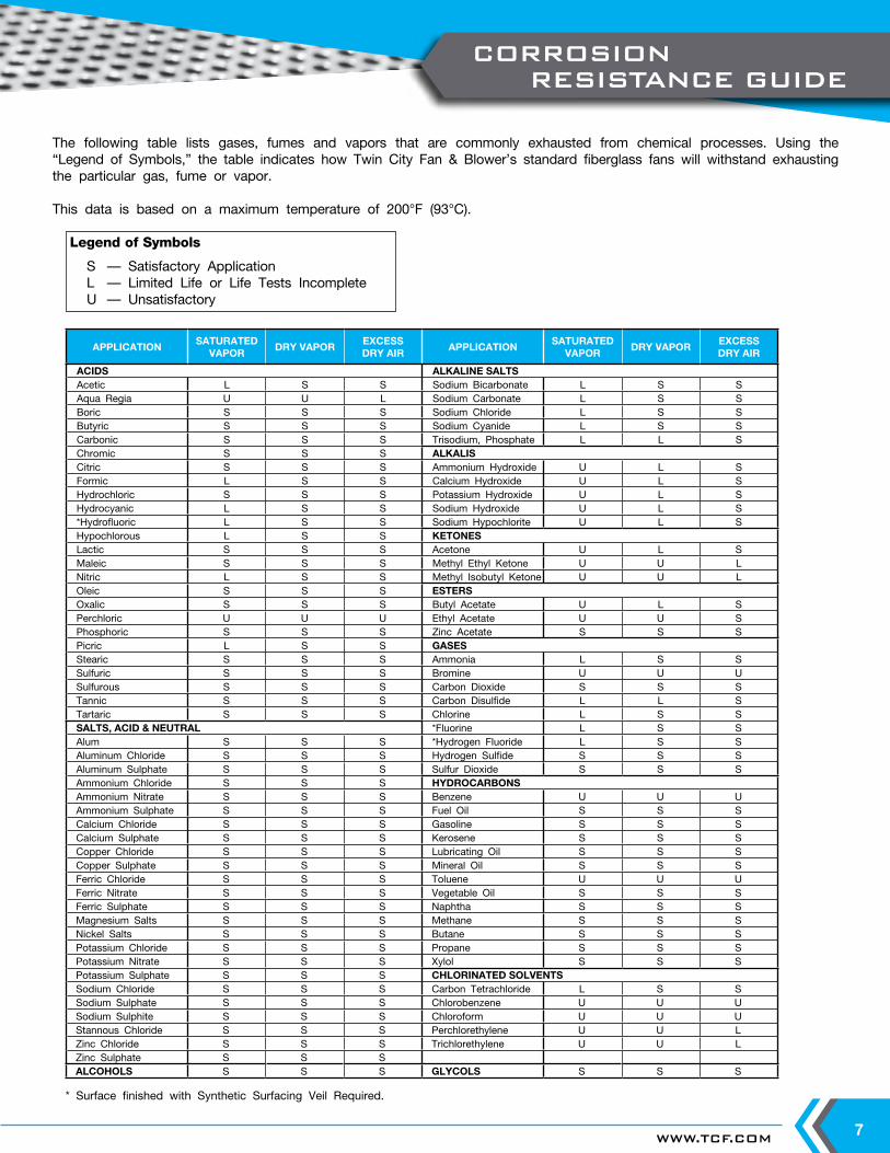
The following table lists gases, fumes and vapors that are commonly exhausted from chemical processes. Using the “Legend of Symbols,” the table indicates how Twin City Fan & Blower’s standard fiberglass fans will withstand exhausting the particular gas, fume or vapor.
This data is based on a maximum temperature of 200°F (93°C).
Legend of Symbols
S — Satisfactory Application L — Limited Life or Life Tests Incomplete U — Unsatisfactory
* Surface finished with Synthetic Surfacing Veil Required.
APPLICATIONSATURATED
VAPORDRY VAPOR
EXCESSDRY AIR
APPLICATIONSATURATED
VAPORDRY VAPOR
EXCESSDRY AIR
ACIDS ALKALINE SALTSAcetic L S S Sodium Bicarbonate L S SAqua Regia U U L Sodium Carbonate L S SBoric S S S Sodium Chloride L S SButyric S S S Sodium Cyanide L S SCarbonic S S S Trisodium, Phosphate L L SChromic S S S ALKALISCitric S S S Ammonium Hydroxide U L SFormic L S S Calcium Hydroxide U L SHydrochloric S S S Potassium Hydroxide U L SHydrocyanic L S S Sodium Hydroxide U L S*Hydrofluoric L S S Sodium Hypochlorite U L SHypochlorous L S S KETONESLactic S S S Acetone U L SMaleic S S S Methyl Ethyl Ketone U U LNitric L S S Methyl Isobutyl Ketone U U LOleic S S S ESTERSOxalic S S S Butyl Acetate U L SPerchloric U U U Ethyl Acetate U U SPhosphoric S S S Zinc Acetate S S SPicric L S S GASESStearic S S S Ammonia L S SSulfuric S S S Bromine U U USulfurous S S S Carbon Dioxide S S STannic S S S Carbon Disulfide L L STartaric S S S Chlorine L S SSALTS, ACID & NEUTRAL *Fluorine L S SAlum S S S *Hydrogen Fluoride L S SAluminum Chloride S S S Hydrogen Sulfide S S SAluminum Sulphate S S S Sulfur Dioxide S S SAmmonium Chloride S S S HYDROCARBONSAmmonium Nitrate S S S Benzene U U UAmmonium Sulphate S S S Fuel Oil S S SCalcium Chloride S S S Gasoline S S SCalcium Sulphate S S S Kerosene S S SCopper Chloride S S S Lubricating Oil S S SCopper Sulphate S S S Mineral Oil S S SFerric Chloride S S S Toluene U U UFerric Nitrate S S S Vegetable Oil S S SFerric Sulphate S S S Naphtha S S SMagnesium Salts S S S Methane S S SNickel Salts S S S Butane S S SPotassium Chloride S S S Propane S S SPotassium Nitrate S S S Xylol S S SPotassium Sulphate S S S CHLORINATED SOLVENTSSodium Chloride S S S Carbon Tetrachloride L S SSodium Sulphate S S S Chlorobenzene U U USodium Sulphite S S S Chloroform U U UStannous Chloride S S S Perchlorethylene U U LZinc Chloride S S S Trichlorethylene U U LZinc Sulphate S S SALCOHOLS S S S GLYCOLS S S S
CORROSION RESISTANCE GUIDE
TWIN CITY FAN - CATALOG 19008
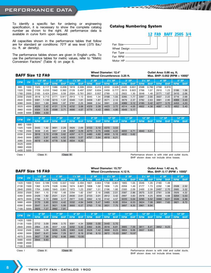
PERFORMANCE DATA
Class I Class II Class III Performance shown is with inlet and outlet ducts. BHP shown does not include drive losses.
To identify a specific fan for ordering or engineering specification, it is necessary to show the complete catalog number as shown to the right. All performance data is available in curve form upon request.
All capacities shown in the performance tables that follow are for standard air conditions: 70°F at sea level (.075 lbs./cu. ft. air density).
The performance tables shown are given in English units. To use the performance tables for metric values, refer to “Metric Conversion Factors” (Table 4) on page 6.
Catalog Numbering System
12 FA9 BAFF 2505 3/4
Fan Size
Wheel Design
Fan Type
Fan RPM
Motor HP
CFM OV1/2" SP 1" SP 11⁄2" SP 2" SP 21⁄2" SP 3" SP 31⁄2" SP 4" SP 5" SP
RPM BHP RPM BHP RPM BHP RPM BHP RPM BHP RPM BHP RPM BHP RPM BHP RPM BHP880 1000 1325 0.117 1586 0.209 1819 0.306 2034 0.412 2233 0.528 2420 0.651 2598 0.782 2768 0.9191320 1500 1729 0.233 1940 0.362 2126 0.497 2297 0.634 2459 0.777 2615 0.922 2766 1.07 2910 1.23 3186 1.561760 2000 2165 0.424 2344 0.59 2504 0.761 2651 0.937 2789 1.12 2922 1.30 3048 1.48 3171 1.67 3410 2.062200 2500 2618 0.713 2771 0.917 2913 1.13 3045 1.34 3168 1.55 3285 1.77 3397 2.00 3507 2.22 3716 2.682640 3000 3081 1.130 3215 1.37 3340 1.61 3459 1.87 3571 2.12 3679 2.37 3782 2.63 3881 2.90 4069 3.433080 3500 3551 1.69 3669 1.97 3781 2.25 3888 2.54 3991 2.83 4089 3.12 4185 3.42 4277 3.72 4453 4.333520 4000 4026 2.42 4131 2.74 4232 3.06 4329 3.39 4423 3.72 4514 4.05 4602 4.38 4687 4.72 4852 5.403960 4500 4504 3.35 4598 3.71 4690 4.07 4779 4.43 4865 4.80 4949 5.174400 5000 4984 4.50
CFM OV6" SP 7" SP 8" SP 9" SP 10" SP 11" SP 12" SP 13" SP 14" SP
RPM BHP RPM BHP RPM BHP RPM BHP RPM BHP RPM BHP RPM BHP RPM BHP RPM BHP880 10001320 1500 3445 1.92 3691 2.29 3926 2.69 4153 3.10 4370 3.531760 2000 3638 2.45 3857 2.86 4067 3.29 4270 3.75 4466 4.22 4655 4.71 4840 5.212200 2500 3916 3.15 4109 3.62 4297 4.11 4480 4.60 4658 5.10 4832 5.622640 3000 4251 3.97 4425 4.52 4593 5.07 4757 5.64 4918 6.213080 3500 4619 4.94 4778 5.56 4934 6.203520 40003960 45004400 5000
BAFF Size 12 FA9Wheel Diameter: 12.4" Outlet Area: 0.88 sq. ft.Wheel Circumference: 3.25 ft. Max. BHP: 0.052 (RPM ÷ 1000)3
Class I Class II Class III Performance shown is with inlet and outlet ducts. BHP shown does not include drive losses.
CFM OV1/2" SP 1" SP 11⁄2" SP 2" SP 21⁄2" SP 3" SP 31⁄2" SP 4" SP 5" SP
RPM BHP RPM BHP RPM BHP RPM BHP RPM BHP RPM BHP RPM BHP RPM BHP RPM BHP1420 1000 1044 0.189 1249 0.337 1432 0.494 1601 0.664 1758 0.851 1905 1.05 2046 1.26 2180 1.482130 1500 1362 0.376 1528 0.584 1674 0.801 1808 1.02 1936 1.25 2059 1.49 2177 1.73 2292 1.98 2508 2.522840 2000 1704 0.683 1845 0.951 1972 1.23 2087 1.51 2196 1.80 2300 2.09 2400 2.39 2497 2.70 2685 3.323550 2500 2061 1.15 2182 1.48 2294 1.82 2397 2.16 2495 2.51 2587 2.86 2675 3.22 2761 3.58 2926 4.324260 3000 2426 1.82 2531 2.21 2630 2.61 2723 3.01 2812 3.42 2897 3.83 2978 4.25 3056 4.68 3204 5.534970 3500 2796 2.72 2889 3.17 2977 3.63 3062 4.10 3142 4.57 3220 5.04 3295 5.52 3368 6.01 3506 6.985680 4000 3170 3.90 3253 4.42 3332 4.94 3409 5.47 3483 6.00 3554 6.53 3624 7.08 3691 7.62 3821 8.726390 4500 3547 5.41 3621 5.99 3693 6.57 3763 7.16 3831 7.75 3897 8.35 3961 8.947100 5000 3925 7.27 3992 7.91
CFM OV6" SP 7" SP 8" SP 9" SP 10" SP 11" SP 12" SP 13" SP 14" SP
RPM BHP RPM BHP RPM BHP RPM BHP RPM BHP RPM BHP RPM BHP RPM BHP RPM BHP1420 10002130 1500 2712 3.09 2906 3.70 3091 4.34 3269 5.00 3440 5.702840 2000 2864 3.95 3037 4.62 3202 5.32 3362 6.05 3516 6.81 3665 7.59 3811 8.41 3952 9.233550 2500 3083 5.08 3235 5.85 3383 6.62 3528 7.42 3668 8.23 3804 9.06 3937 9.934260 3000 3347 6.41 3484 7.29 3617 8.19 3746 9.10 3872 10.03 3997 10.974970 3500 3637 7.98 3762 8.98 3885 10.005680 4000 3944 9.836390 45007100 5000
BAFF Size 16 FA9Wheel Diameter: 15.75" Outlet Area: 1.42 sq. ft.Wheel Circumference: 4.12 ft. Max. BHP: 0.17 (RPM ÷ 1000)3

WWW.TCF.COM 9
PERFORMANCE DATA
Class I Class II Class III Performance shown is with inlet and outlet ducts. BHP shown does not include drive losses.
CFM OV1/2" SP 1" SP 11⁄2" SP 2" SP 21⁄2" SP 3" SP 31⁄2" SP 4" SP 5" SP
RPM BHP RPM BHP RPM BHP RPM BHP RPM BHP RPM BHP RPM BHP RPM BHP RPM BHP2220 1000 836 0.296 1000 0.527 1147 0.773 1282 1.04 1407 1.33 1525 1.64 1637 1.97 1744 2.323330 1500 1091 0.589 1224 0.915 1340 1.25 1448 1.60 1550 1.96 1649 2.33 1743 2.70 1834 3.09 2008 3.934440 2000 1366 1.07 1478 1.49 1580 1.92 1672 2.37 1759 2.82 1842 3.27 1922 3.74 1999 4.21 2150 5.195550 2500 1651 1.80 1748 2.32 1837 2.84 1920 3.38 1998 3.92 2072 4.48 2142 5.04 2211 5.61 2343 6.766660 3000 1944 2.85 2028 3.46 2107 4.08 2182 4.71 2253 5.35 2320 5.99 2385 6.65 2447 7.31 2566 8.657770 3500 2241 4.27 2315 4.97 2385 5.69 2453 6.42 2517 7.15 2580 7.90 2640 8.65 2698 9.40 2808 10.928880 4000 2540 6.12 2606 6.92 2670 7.74 2731 8.56 2790 9.39 2847 10.22 2903 11.07 2957 11.93 3060 13.639990 4500 2842 8.47 2901 9.37 2959 10.29 3015 11.21 3069 12.13 3122 13.07 3173 14.0011100 5000 3145 11.39 3199 12.39
CFM OV6" SP 7" SP 8" SP 9" SP 10" SP 11" SP 12" SP 13" SP 14" SP
RPM BHP RPM BHP RPM BHP RPM BHP RPM BHP RPM BHP RPM BHP RPM BHP RPM BHP2220 10003330 1500 2171 4.83 2326 5.79 2474 6.78 2617 7.83 2753 8.904440 2000 2293 6.18 2431 7.21 2563 8.31 2691 9.45 2814 10.64 2934 11.87 3050 13.13 3164 14.445550 2500 2469 7.94 2590 9.14 2709 10.36 2824 11.60 2936 12.86 3045 14.17 3152 15.536660 3000 2681 10.03 2790 11.40 2896 12.80 2999 14.23 3100 15.67 3200 17.157770 3500 2913 12.48 3013 14.05 3111 15.648880 4000 3159 15.389990 450011100 5000
BAFF Size 20 FA9Wheel Diameter: 19.68" Outlet Area: 2.22 sq. ft.Wheel Circumference: 5.15 ft. Max. BHP: 0.53 (RPM ÷ 1000)3
Class I Class II Class III Performance shown is with inlet and outlet ducts. BHP shown does not include drive losses.
CFM OV1/2" SP 1" SP 11⁄2" SP 2" SP 21⁄2" SP 3" SP 31⁄2" SP 4" SP 5" SP
RPM BHP RPM BHP RPM BHP RPM BHP RPM BHP RPM BHP RPM BHP RPM BHP RPM BHP3530 1000 664 0.471 794 0.839 910 1.23 1017 1.65 1117 2.12 1210 2.61 1299 3.13 1384 3.685295 1500 866 0.936 972 1.46 1064 1.99 1150 2.55 1231 3.12 1309 3.70 1384 4.30 1456 4.92 1594 6.267060 2000 1085 1.71 1174 2.37 1254 3.06 1328 3.77 1397 4.48 1463 5.21 1526 5.95 1587 6.70 1706 8.248825 2500 1312 2.87 1389 3.69 1459 4.52 1525 5.38 1587 6.25 1645 7.12 1701 8.01 1756 8.92 1860 10.7510590 3000 1545 4.54 1611 5.51 1674 6.50 1733 7.50 1789 8.51 1843 9.55 1894 10.58 1944 11.6412355 3500 1780 6.79 1839 7.92 1895 9.06 1948 10.21 2000 11.39
CFM OV6" SP 7" SP 8" SP 9" SP 10" SP 11" SP 12" SP 13" SP 14" SP
RPM BHP RPM BHP RPM BHP RPM BHP RPM BHP RPM BHP RPM BHP RPM BHP RPM BHP3530 10005295 1500 1723 7.68 1846 9.20 1963 10.777060 2000 1820 9.82 1930 11.488825 2500 1960 12.62
BAFF Size 25 FA9Wheel Diameter: 24.8" Outlet Area: 3.53 sq. ft.Wheel Circumference: 6.49 ft. Max. BHP: 1.68 (RPM ÷ 1000)3
Twin City Fan
Twin City Fan
TWIN CITY FAN - CATALOG 190010
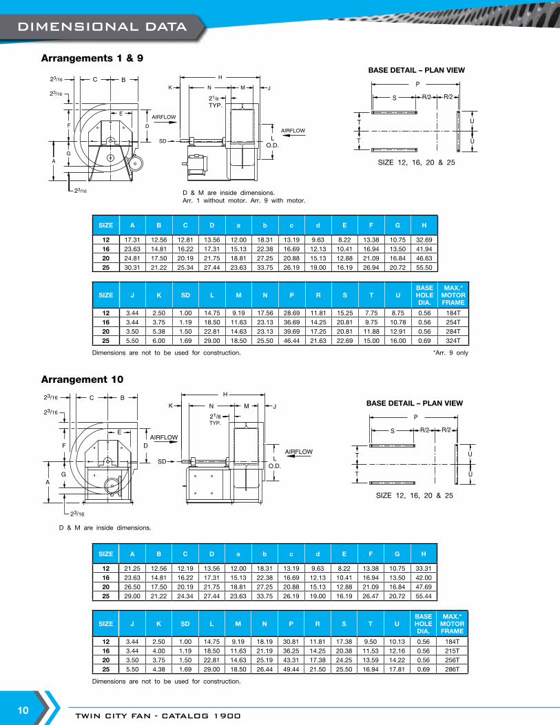
DIMENSIONAL DATA
Arrangement 10
C B
D
AG
F
E
H
M JNK
LO.D.
AIRFLOW
AIRFLOW
23/16
23/16
21/8TYP.
23/16
SD
P
S R/2 R/2
T
T
U
U
BASE DETAIL – PLAN VIEW
SIZE 12, 16, 20 & 25
D & M are inside dimensions.
Dimensions are not to be used for construction.
SIZE A B C D a b c d E F G H
12 21.25 12.56 12.19 13.56 12.00 18.31 13.19 9.63 8.22 13.38 10.75 33.3116 23.63 14.81 16.22 17.31 15.13 22.38 16.69 12.13 10.41 16.94 13.50 42.0020 26.50 17.50 20.19 21.75 18.81 27.25 20.88 15.13 12.88 21.09 16.84 47.6925 29.00 21.22 24.34 27.44 23.63 33.75 26.19 19.00 16.19 26.47 20.72 55.44
SIZE J K SD L M N P R S T UBASE HOLE DIA.
MAX.*MOTORFRAME
12 3.44 2.50 1.00 14.75 9.19 18.19 30.81 11.81 17.38 9.50 10.13 0.56 184T16 3.44 4.00 1.19 18.50 11.63 21.19 36.25 14.25 20.38 11.53 12.16 0.56 215T20 3.50 3.75 1.50 22.81 14.63 25.19 43.31 17.38 24.25 13.59 14.22 0.56 256T25 5.50 4.38 1.69 29.00 18.50 26.44 49.44 21.50 25.50 16.94 17.81 0.69 286T
Arrangements 1 & 9
C B23/16
21/8TYP.
23/16
23/16
F
AG
E
D
AIRFLOW
AIRFLOW
H
K N M J
LO.D.
SD
P
S R/2 R/2
T
T
U
U
BASE DETAIL – PLAN VIEW
SIZE 12, 16, 20 & 25
D & M are inside dimensions.Arr. 1 without motor. Arr. 9 with motor.
*Arr. 9 onlyDimensions are not to be used for construction.
SIZE A B C D a b c d E F G H
12 17.31 12.56 12.81 13.56 12.00 18.31 13.19 9.63 8.22 13.38 10.75 32.6916 23.63 14.81 16.22 17.31 15.13 22.38 16.69 12.13 10.41 16.94 13.50 41.9420 24.81 17.50 20.19 21.75 18.81 27.25 20.88 15.13 12.88 21.09 16.84 46.6325 30.31 21.22 25.34 27.44 23.63 33.75 26.19 19.00 16.19 26.94 20.72 55.50
SIZE J K SD L M N P R S T UBASE HOLE DIA.
MAX.*MOTORFRAME
12 3.44 2.50 1.00 14.75 9.19 17.56 28.69 11.81 15.25 7.75 8.75 0.56 184T16 3.44 3.75 1.19 18.50 11.63 23.13 36.69 14.25 20.81 9.75 10.78 0.56 254T20 3.50 5.38 1.50 22.81 14.63 23.13 39.69 17.25 20.81 11.88 12.91 0.56 284T25 5.50 6.00 1.69 29.00 18.50 25.50 46.44 21.63 22.69 15.00 16.00 0.69 324T
WWW.TCF.COM 11
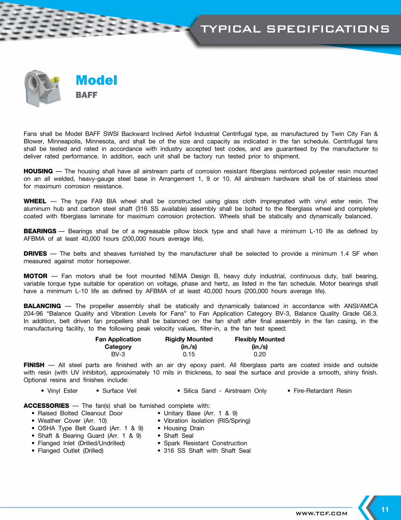
Fans shall be Model BAFF SWSI Backward Inclined Airfoil Industrial Centrifugal type, as manufactured by Twin City Fan & Blower, Minneapolis, Minnesota, and shall be of the size and capacity as indicated in the fan schedule. Centrifugal fans shall be tested and rated in accordance with industry accepted test codes, and are guaranteed by the manufacturer to deliver rated performance. In addition, each unit shall be factory run tested prior to shipment.
HOUSING — The housing shall have all airstream parts of corrosion resistant fiberglass reinforced polyester resin mounted on an all welded, heavy-gauge steel base in Arrangement 1, 9 or 10. All airstream hardware shall be of stainless steel for maximum corrosion resistance.
WHEEL — The type FA9 BIA wheel shall be constructed using glass cloth impregnated with vinyl ester resin. The aluminum hub and carbon steel shaft (316 SS available) assembly shall be bolted to the fiberglass wheel and completely coated with fiberglass laminate for maximum corrosion protection. Wheels shall be statically and dynamically balanced.
BEARINGS — Bearings shall be of a regreasable pillow block type and shall have a minimum L-10 life as defined by AFBMA of at least 40,000 hours (200,000 hours average life).
DRIVES — The belts and sheaves furnished by the manufacturer shall be selected to provide a minimum 1.4 SF when measured against motor horsepower.
MOTOR — Fan motors shall be foot mounted NEMA Design B, heavy duty industrial, continuous duty, ball bearing, variable torque type suitable for operation on voltage, phase and hertz, as listed in the fan schedule. Motor bearings shall have a minimum L-10 life as defined by AFBMA of at least 40,000 hours (200,000 hours average life).
BALANCING — The propeller assembly shall be statically and dynamically balanced in accordance with ANSI/AMCA 204-96 “Balance Quality and Vibration Levels for Fans” to Fan Application Category BV-3, Balance Quality Grade G6.3. In addition, belt driven fan propellers shall be balanced on the fan shaft after final assembly in the fan casing, in the manufacturing facility, to the following peak velocity values, filter-in, a the fan test speed:
Fan Application Rigidly Mounted Flexibly Mounted Category (in./s) (in./s) BV-3 0.15 0.20
FINISH — All steel parts are finished with an air dry epoxy paint. All fiberglass parts are coated inside and outside with resin (with UV inhibitor), approximately 10 mils in thickness, to seal the surface and provide a smooth, shiny finish. Optional resins and finishes include:
• Vinyl Ester • Surface Veil • Silica Sand - Airstream Only • Fire-Retardant Resin
ACCESSORIES — The fan(s) shall be furnished complete with: • Raised Bolted Cleanout Door • Unitary Base (Arr. 1 & 9) • Weather Cover (Arr. 10) • Vibration Isolation (RIS/Spring) • OSHA Type Belt Guard (Arr. 1 & 9) • Housing Drain • Shaft & Bearing Guard (Arr. 1 & 9) • Shaft Seal • Flanged Inlet (Drilled/Undrilled) • Spark Resistant Construction • Flanged Outlet (Drilled) • 316 SS Shaft with Shaft Seal
ModelBAFF
TYPICAL SPECIFICATIONS
TWIN CITY FAN & BLOWERWWW.TCF.COM
5959 TRENTON LANE N | MINNEAPOLIS, MN 55442 | PHONE: 763-551-7600 | FAX: 763-551-7601
CENTRIFUGAL FANS | UTILITY SETS | PLENUM & PLUG FANS | INLINE CENTRIFUGAL FANS
MIXED FLOW FANS | TUBEAXIAL & VANEAXIAL FANS | PROPELLER WALL FANS | PROPELLER ROOF VENTILATORS
CENTRIFUGAL ROOF & WALL EXHAUSTERS | CEILING VENTILATORS | GRAVITY VENTILATORS | DUCT BLOWERS
RADIAL BLADED FANS | RADIAL TIP FANS | HIGH EFFICIENCY INDUSTRIAL FANS | PRESSURE BLOWERS
LABORATORY EXHAUST FANS | FILTERED SUPPLY FANS | MANCOOLERS | FIBERGLASS FANS | CUSTOM FANS
INDUSTRIAL PROCESS ANDCOMMERCIAL VENTILATION SYSTEMS
©2018 Twin City Fan Companies, Ltd., Minneapolis, MN. All rights reserved. Catalog illustrations cover the general appearance of Twin City
Fan & Blower products at the time of publication and we reserve the right to make changes in design and construction at any time without notice.


![APRIL and BAFF: novel biomarkers for central nervous ...BAFF interacts with both TACI, BCMA, and a third re-ceptor, called BAFF-receptor (BAFF-R) [23, 24]. APRIL and BAFF have been](https://static.documents.pub/doc/80x56/61118380ec06d454af1be029/april-and-baff-novel-biomarkers-for-central-nervous-baff-interacts-with-both.jpg)


