Presented courtesy of Aetna Plastics 1-800-634-3074 www.aetnaplastics.com
Aickinstrut framing products for your non-metallic infrastructure applications
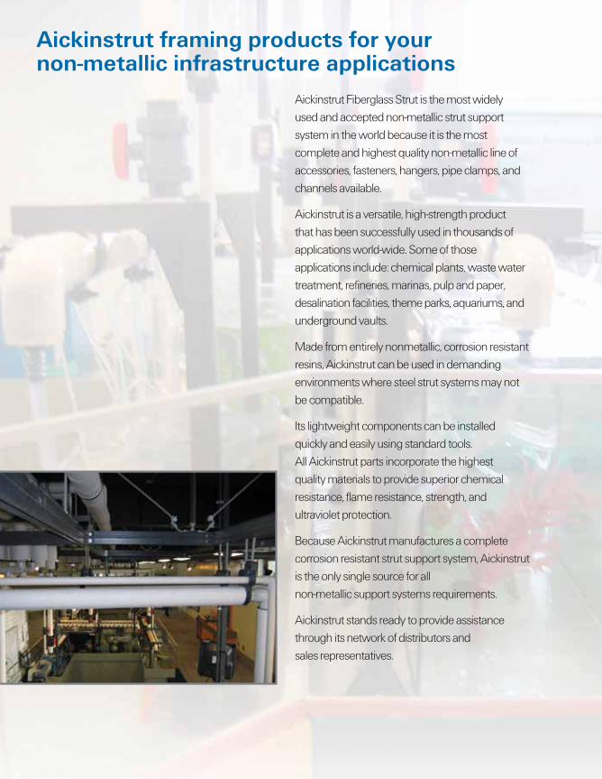
Aickinstrut Fiberglass Strut is the most widely used and accepted non-metallic strut support system in the world because it is the most complete and highest quality non-metallic line of accessories, fasteners, hangers, pipe clamps, and channels available.
Aickinstrut is a versatile, high-strength product that has been successfully used in thousands of applications world-wide. Some of those applications include: chemical plants, waste water treatment, refineries, marinas, pulp and paper, desalination facilities, theme parks, aquariums, and underground vaults.
Made from entirely nonmetallic, corrosion resistant resins, Aickinstrut can be used in demanding environments where steel strut systems may not be compatible.
Its lightweight components can be installed quickly and easily using standard tools. All Aickinstrut parts incorporate the highest quality materials to provide superior chemical resistance, flame resistance, strength, and ultraviolet protection.
Because Aickinstrut manufactures a complete corrosion resistant strut support system, Aickinstrut is the only single source for all non-metallic support systems requirements.
Aickinstrut stands ready to provide assistance through its network of distributors and sales representatives.
Sealers and CoatingsAickinzap ...................................................................................................36Aickincoat .................................................................................................36
IndexAickinstrut/Aickinshape/AickingratePart Number Index ..................................................................................57Other Fiberglass Products .....................................................................58AEG Line Card ..........................................................................................59
4 Aickinstrut
AICKINSTRUT FABRICATIONThe installation of fi berglass channel and accessories is similar to the installation of metallic channel and acces-sories. All standard installation practices and procedures apply. In general, special handling is not required. Fabrica-tion of Aickinstrut components requires just three simple operations; cutting, drilling and sealing as described below.
Cutting – Cutting can be accomplished with a wide variety of saws. Hand held saws, such as hack saws (24 to 32 teeth per inch) are suitable when a few number of cuts are required. For frequent cutting, a circular power saw with a carbide-tipped masonry blade yields the best results and the greatest number of cuts. When using a power saw, dust fi lter masks, gloves and long sleeve clothing should be worn.
Drilling – Any standard twist bit, even when used with bat-tery-powered drills will work well. Carbide-tipped drill bits are recommended.
Sealing – To protect against future migration of corrosive elements into the cut sections, all cuts and holes should be properly sealed using Aickincoat or Aickinzap.
LABOR SAVINGSAickinstrut fi berglass structural members can be cut and drilled at a much faster rate than steel. Typically, fi berglass can be fabricated in less than half the time. As a result, substantial labor savings will be realized. Also, Aickinstrut products average 1⁄3 the weight of their steel counterparts, making them much easier to handle on the job site.
RELATIVE MATERIAL COSTSAickinstrut materials are advantageously priced relative to specialty metals traditionally used in corrosive environ-ments. Aickinstrut, even though slightly more expensive than pre-galvanized channel, can be used with the knowl-edge that it will not have to be maintained regularly or replaced after a brief time. Should pre-galvanized channel have to be replaced once, its cost far outweighs the expense of doing the initial installation with Aickinstrut.
MATERIALThe fi nished Aickinstrut application will utilize a combina-tion of materials from the following resin families:
Material Code Material E PVC (extruded) P Polyester (pultruded) V Vinyl ester (pultruded) PU Polyurethane (injection molded) PP Polypropylene (injection molded) N Nylon (injection molded)
The ability of each material to handle high and low tem-peratures, chemical exposures and static loads is covered in each of the following sections. By using these criteria, you will be able to select the optimal Aickinstrut Channel, Fit-tings and Accessories for your particular applications.
OPERATING ENVIRONMENTIn order to design an Aickinstrut system for your appli-cation, consideration should be given to the maximum operating conditions. These “worst case” conditions will determine which type of Aickinstrut materials are best suited for your application. The three “worst case” operat-ing conditions to consider are:
Temperature
Chemical Environment
Loading
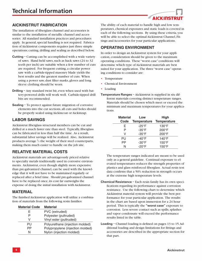
Temperature Ranges – Aickinstrut is supplied in six dif-ferent materials covering distinct temperature ranges. Materials should be chosen which meet or exceed the minimum and maximum temperatures for your applica-tions.
Material Low High Code Temperature Temperature E -25°F 130°F P -35°F 200°F V -35°F 200°F PU -40°F 140°F PP -30°F 150°F N -20°F 150°F
The temperature ranges indicated are meant to be used only as a general guideline. Continual exposure to el-evated temperatures reduces the strength properties of plastics and glass reinforced fi berglass. Actual resin test data confi rms that a 50% reduction in strength occurs at the extreme high temperature levels.
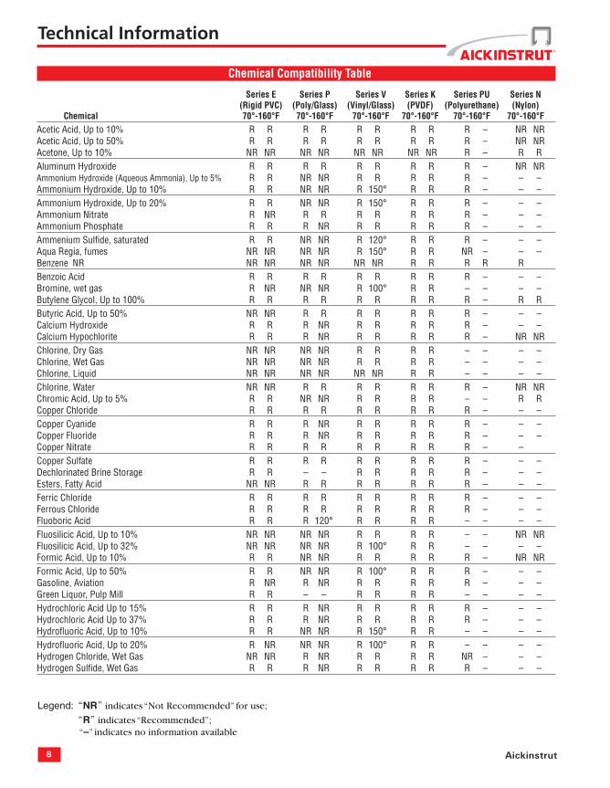
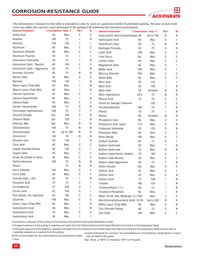
Chemical Resistance – Each resin family has its own speci-fi cations regarding its performance against corrosion resistance. Use the following chart to determine which Aickinstrut material system will provide the best per-formance for your particular application. The results in the chart are based upon immersion for a 24 hour period. This is typically the “worst case” exposure to corrosion. Less severe contact such as spills, splashes and vapor condensate will exceed the performance results listed in the table.
Loading – Channel loading is defi ned on pages 13 to 15. Ad-ditional loading and design limitations for fi ttings and accessories are described in the appropriate section for that part.
•
•
•
Technical Information
5www.alliedeg.com
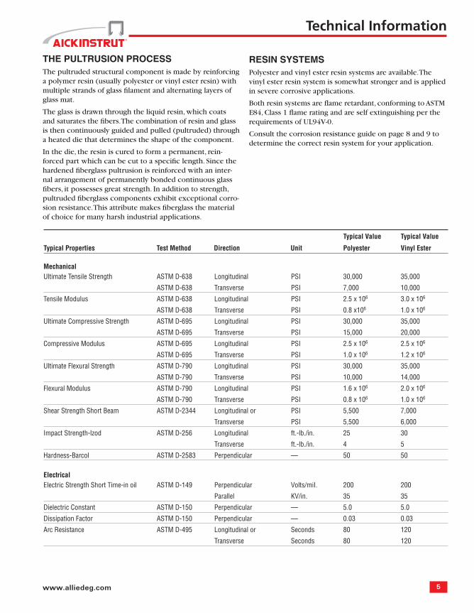
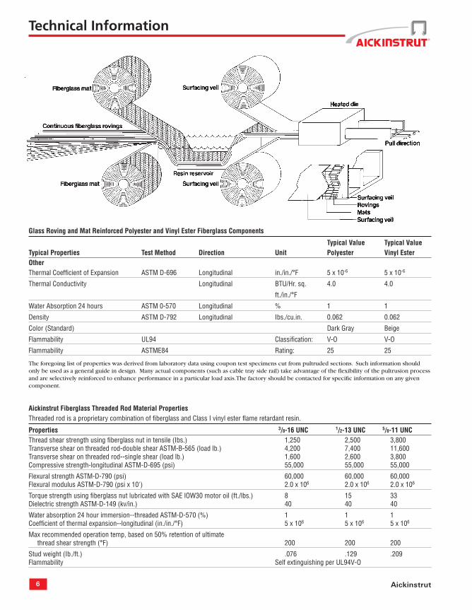
THE PULTRUSION PROCESS The pultruded structural component is made by reinforcing a polymer resin (usually polyester or vinyl ester resin) with multiple strands of glass fi lament and alternating layers of glass mat.
The glass is drawn through the liquid resin, which coats and saturates the fi bers. The combination of resin and glass is then continuously guided and pulled (pultruded) through a heated die that determines the shape of the component.
In the die, the resin is cured to form a permanent, rein-forced part which can be cut to a specifi c length. Since the hardened fi berglass pultrusion is reinforced with an inter-nal arrangement of permanently bonded continuous glass fi bers, it possesses great strength. In addition to strength, pultruded fi berglass components exhibit exceptional corro-sion resistance. This attribute makes fi berglass the material of choice for many harsh industrial applications.
RESIN SYSTEMS Polyester and vinyl ester resin systems are available. The vinyl ester resin system is somewhat stronger and is applied in severe corrosive applications.
Both resin systems are fl ame retardant, conforming to ASTM E84, Class 1 fl ame rating and are self extinguishing per the requirements of UL94V-0.
Consult the corrosion resistance guide on page 8 and 9 to determine the correct resin system for your application.
Typical Value Typical Value
Typical Properties Test Method Direction Unit Polyester Vinyl Ester
Arc Resistance ASTM D-495 Longitudinal or Seconds 80 120
Transverse Seconds 80 120
Technical Information
6 Aickinstrut
Glass Roving and Mat Reinforced Polyester and Vinyl Ester Fiberglass Components
Typical Value Typical ValueTypical Properties Test Method Direction Unit Polyester Vinyl EsterOtherThermal Coeffi cient of Expansion ASTM D-696 Longitudinal in./in./°F 5 x 10⁻⁶ 5 x 10⁻⁶
Water Absorption 24 hours ASTM 0-570 Longitudinal % 1 1
Density ASTM D-792 Longitudinal Ibs./cu.in. 0.062 0.062
Color (Standard) Dark Gray Beige
Flammability UL94 Classifi cation: V-O V-O
Flammability ASTME84 Rating: 25 25
The foregoing list of properties was derived from laboratory data using coupon test specimens cut from pultruded sections. Such information should only be used as a general guide in design. Many actual components (such as cable tray side rail) take advantage of the fl exibility of the pultrusion process and are selectively reinforced to enhance performance in a particular load axis. The factory should be contacted for specifi c information on any given component.
Aickinstrut Fiberglass Threaded Rod Material Properties Threaded rod is a proprietary combination of fi berglass and Class I vinyl ester fl ame retardant resin.
Properties 3/8-16 UNC 1/2-13 UNC 5/8-11 UNCThread shear strength using fi berglass nut in tensile (Ibs.) 1,250 2,500 3,800Transverse shear on threaded rod-double shear ASTM-B-565 (load lb.) 4,200 7,400 11,600Transverse shear on threaded rod--single shear (load lb.) 1,600 2,600 3,800Compressive strength-longitudinal ASTM-D-695 (psi) 55,000 55,000 55,000
Flexural strength ASTM-D-790 (psi) 60,000 60,000 60,000Flexural modulus ASTM-D-790 (psi x 10') 2.0 x 10⁶ 2.0 x 10⁶ 2.0 x 10⁶
Torque strength using fi berglass nut lubricated with SAE lOW30 motor oil (ft./lbs.) 8 15 33Dielectric strength ASTM-D-149 (kv/in.) 40 40 40
Water absorption 24 hour immersion--threaded ASTM-D-570 (%) 1 1 1Coeffi cient of thermal expansion--longitudinal (in./in./°F) 5 x 10⁶ 5 x 10⁶ 5 x 10⁶
Max recommended operation temp, based on 50% retention of ultimate thread shear strength (°F) 200 200 200
Stud weight (Ib./ft.) .076 .129 .209Flammability Self extinguishing per UL94V-O
Technical Information
7www.alliedeg.com
4.4 Channel section lengths shall be supplied in 10' or 20' lengths (±1⁄8").
4.5 Universal Pipe Clamps shall have full interlocking contact with interior channel fl anges to maximize pull-out resistance and be adjustable to accommo-date a minimum 3⁄4" variance in piping or conduit O.D. sizes.
5.0 STANDARDS
5.1 Glass reinforced and PVC channels covered in this specifi cation shall have a fl ame spread rating of 25 or less when tested per ASTM E84 and meet the requirements of UL 94V0 thereby qualifying them as Class 1 material in the Uniform Building Code.
5.2 Glass reinforced channels covered in this speci-fi cation shall comply with the requirements of ASTM D 3917 and ASTM D 4385 which govern the dimensional tolerance and visual defects of pultruded shapes.
6.0 GENERAL
6.1 Aickinstrut Nonmetallic Channel Framing shall be furnished as a system which includes all the nec-essary fasteners, channel splice plates, brackets, sealants, hangers, pipe clamps, etc.
6.2 Nonmetallic fasteners shall be manufactured from long glass fi ber reinforced polyurethane to ensure maximum strength and corrosion resistance.
6.3 All components of the Aickinstrut Channel Fram-ing System shall be nonmetallic except where type 316 stainless steel hardware is used as part of the assembly.
6.4 Aickinstrut is manufactured by Aickinstrut, a subsidiary of T. J. Cope, Philadelphia, Pennsylvania, 1-800-426-4293.
6.5 The manufacturer shall not have had less than 10 years experience in manufacturing strut systems.
6.6 All products are manufactured in the United States of America.
Aickinstrut Specifi cations
1.0 SCOPE
1.1 This specifi cation covers the requirements for the Aickinstrut Nonmetallic Channel Framing System.
2.0 MATERIAL
2.1 FRP channel shall be of pultruded glass reinforced polyester or vinyl ester resin having the physical property values listed in this catalog.
2.2 PVC channel shall be of extruded polyvinyl chlo-ride having the physical property values listed in this catalog.
2.3 Some accessories shall be of injection molded, 40% long glass fi ber reinforced polyurethane, poly-propylene or nylon.
3.0 COMPOSITION
3.1 Glass reinforced channel shall have a synthetic surfacing veil applied on exterior surfaces to improve weatherability and inhibit ultraviolet deg-radation. An ultraviolet stabilizer shall be incor-porated in the resin formulation to further inhibit ultraviolet degradation.
3.2 PVC channel shall be manufactured from a U.V. stabilized resin and incorporate dark gray pigment to improve weatherability and inhibit ultraviolet degradation.
4.0 STRUCTURAL DESIGN
4.1 Channel shall incorporate Aickinstrut's patented fl ange profi le design which allows full and posi-tive interlocking contact of channel accessories and prohibits premature fl ange failure from torqued accessories.
4.2 Channel profi le dimensions shall be:
15⁄8" x 15⁄8" x 1⁄4", 11⁄2" x 11⁄2" x 1⁄8", or 11⁄2" x 11⁄8" x 1⁄8".
4.3 All 15⁄8" x 15⁄8" channel profi les shall have a mini-mum pull out resistance of 1,000 pounds when load is applied over a 3⁄8" long section of the inside fl anges.
Technical Information
8 Aickinstrut
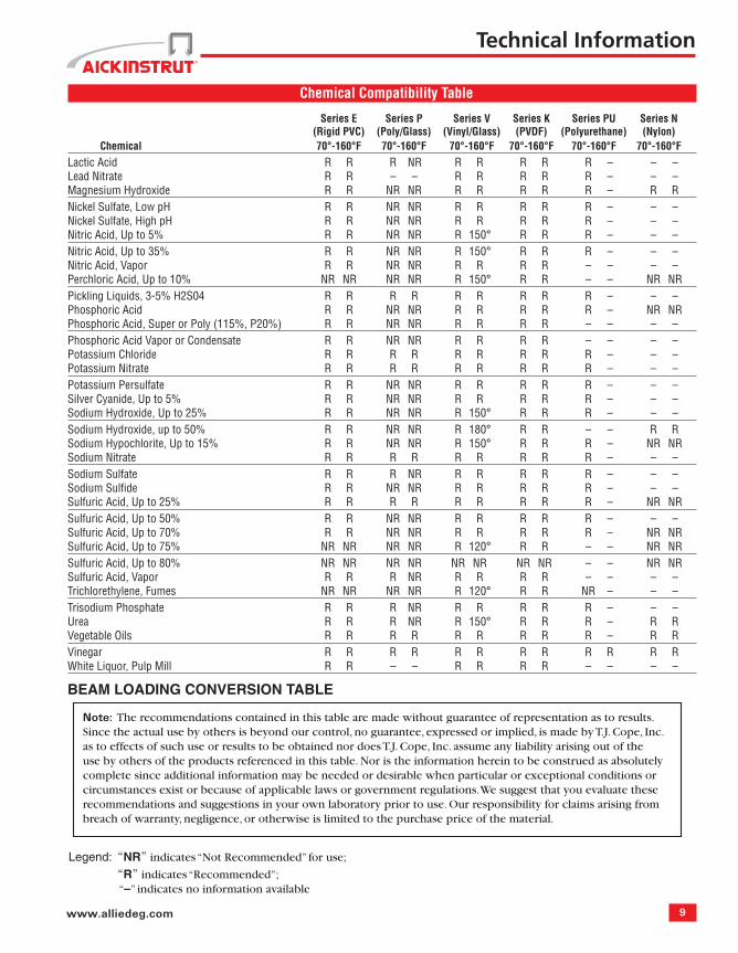
Chemical Compatibility Table
Series E Series P Series V Series K Series PU Series N (Rigid PVC) (Poly/Glass) (Vinyl/Glass) (PVDF) (Polyurethane) (Nylon) Chemical 70°-160°F 70°-160°F 70°-160°F 70°-160°F 70°-160°F 70°-160°FAcetic Acid, Up to 10% R R R R R R R R R – NR NRAcetic Acid, Up to 50% R R R R R R R R R – NR NRAcetone, Up to 10% NR NR NR NR NR NR NR NR R – R RAluminum Hydroxide R R R R R R R R R – NR NRAmmonium Hydroxide (Aqueous Ammonia), Up to 5% R R NR NR R R R R R – – –Ammonium Hydroxide, Up to 10% R R NR NR R 150° R R R – – –Ammonium Hydroxide, Up to 20% R R NR NR R 150° R R R – – –Ammonium Nitrate R NR R R R R R R R – – –Ammonium Phosphate R R R NR R R R R R – – –Ammenium Sulfi de, saturated R R NR NR R 120° R R R – – –Aqua Regia, fumes NR NR NR NR R 150° R R NR – – –Benzene NR NR NR NR NR NR NR R R R R RBenzoic Acid R R R R R R R R R – – –Bromine, wet gas R NR NR NR R 100° R R – – – –Butylene Glycol, Up to 100% R R R R R R R R R – R RButyric Acid, Up to 50% NR NR R R R R R R R – – –Calcium Hydroxide R R R NR R R R R R – – –Calcium Hypochlorite R R R NR R R R R R – NR NRChlorine, Dry Gas NR NR NR NR R R R R – – – –Chlorine, Wet Gas NR NR NR NR R R R R – – – –Chlorine, Liquid NR NR NR NR NR NR R R – – – –Chlorine, Water NR NR R R R R R R R – NR NRChromic Acid, Up to 5% R R NR NR R R R R – – R RCopper Chloride R R R R R R R R R – – –Copper Cyanide R R R NR R R R R R – – –Copper Fluoride R R R NR R R R R R – – –Copper Nitrate R R R R R R R R R – –Copper Sulfate R R R R R R R R R – – –Dechlorinated Brine Storage R R – – R R R R R – – –Esters, Fatty Acid NR NR R R R R R R R – – –Ferric Chloride R R R R R R R R R – – –Ferrous Chloride R R R R R R R R R – – –Fluoboric Acid R R R 120° R R R R – – – –Fluosilicic Acid, Up to 10% NR NR NR NR R R R R – – NR NRFluosilicic Acid, Up to 32% NR NR NR NR R 100° R R – – – –Formic Acid, Up to 10% R R NR NR R R R R R – NR NRFormic Acid, Up to 50% R R NR NR R 100° R R R – – –Gasoline, Aviation R NR R NR R R R R R – – –Green Liquor, Pulp Mill R R – – R R R R – – – –Hydrochloric Acid Up to 15% R R R NR R R R R R – – –Hydrochloric Acid Up to 37% R R R NR R R R R R – – –Hydrofl uoric Acid, Up to 10% R R NR NR R 150° R R – – – –Hydrofl uoric Acid, Up to 20% R NR NR NR R 100° R R – – – –Hydrogen Chloride, Wet Gas NR NR R NR R R R R NR – – –Hydrogen Sulfi de, Wet Gas R R R NR R R R R R – – –
Legend: “NR” indicates “Not Recommended” for use;
“R” indicates “Recommended”; “–” indicates no information available
Technical Information
9www.alliedeg.com
Chemical Compatibility Table
Series E Series P Series V Series K Series PU Series N (Rigid PVC) (Poly/Glass) (Vinyl/Glass) (PVDF) (Polyurethane) (Nylon) Chemical 70°-160°F 70°-160°F 70°-160°F 70°-160°F 70°-160°F 70°-160°FLactic Acid R R R NR R R R R R – – –Lead Nitrate R R – – R R R R R – – –Magnesium Hydroxide R R NR NR R R R R R – R RNickel Sulfate, Low pH R R NR NR R R R R R – – –Nickel Sulfate, High pH R R NR NR R R R R R – – –Nitric Acid, Up to 5% R R NR NR R 150° R R R – – –Nitric Acid, Up to 35% R R NR NR R 150° R R R – – –Nitric Acid, Vapor R R NR NR R R R R – – – –Perchloric Acid, Up to 10% NR NR NR NR R 150° R R – – NR NRPickling Liquids, 3-5% H2S04 R R R R R R R R R – – –Phosphoric Acid R R NR NR R R R R R – NR NRPhosphoric Acid, Super or Poly (115%, P20%) R R NR NR R R R R – – – –Phosphoric Acid Vapor or Condensate R R NR NR R R R R – – – –Potassium Chloride R R R R R R R R R – – –Potassium Nitrate R R R R R R R R R – – –Potassium Persulfate R R NR NR R R R R R – – –Silver Cyanide, Up to 5% R R NR NR R R R R R – – –Sodium Hydroxide, Up to 25% R R NR NR R 150° R R R – – –Sodium Hydroxide, up to 50% R R NR NR R 180° R R – – R RSodium Hypochlorite, Up to 15% R R NR NR R 150° R R R – NR NRSodium Nitrate R R R R R R R R R – – –Sodium Sulfate R R R NR R R R R R – – –Sodium Sulfi de R R NR NR R R R R R – – –Sulfuric Acid, Up to 25% R R R R R R R R R – NR NRSulfuric Acid, Up to 50% R R NR NR R R R R R – – –Sulfuric Acid, Up to 70% R R NR NR R R R R R – NR NRSulfuric Acid, Up to 75% NR NR NR NR R 120° R R – – NR NRSulfuric Acid, Up to 80% NR NR NR NR NR NR NR NR – – NR NRSulfuric Acid, Vapor R R R NR R R R R – – – –Trichlorethylene, Fumes NR NR NR NR R 120° R R NR – – –Trisodium Phosphate R R R NR R R R R R – – –Urea R R R NR R 150° R R R – R RVegetable Oils R R R R R R R R R – R RVinegar R R R R R R R R R R R RWhite Liquor, Pulp Mill R R – – R R R R – – – –
BEAM LOADING CONVERSION TABLE
Note: The recommendations contained in this table are made without guarantee of representation as to results. Since the actual use by others is beyond our control, no guarantee, expressed or implied, is made by T.J. Cope, Inc. as to effects of such use or results to be obtained nor does T.J. Cope, Inc. assume any liability arising out of the use by others of the products referenced in this table. Nor is the information herein to be construed as absolutely complete since additional information may be needed or desirable when particular or exceptional conditions or circumstances exist or because of applicable laws or government regulations. We suggest that you evaluate these recommendations and suggestions in your own laboratory prior to use. Our responsibility for claims arising from breach of warranty, negligence, or otherwise is limited to the purchase price of the material.
Technical Information
Legend: “NR” indicates “Not Recommended” for use;
“R” indicates “Recommended”; “–” indicates no information available
10 Aickinstrut
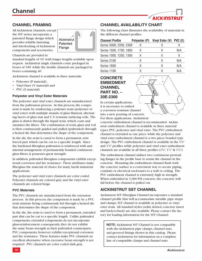
NOTE: Aickinstrut SST Channel is not compatible with the Aickinstrut pipe clamps, channel nuts, and grooved fi ttings shown in this catalog. Please contact Aickinstrut for information on a complete line of compatible clamps and channel nuts.
AickinstrutPatentedFlange
Channel
CHANNEL FRAMINGAll Aickinstrut channels, except the SST series, incorporate a patented fl ange design which provides reliable fastening and interlocking of Aickinstrut components and accessories.
Channels are provided in standard lengths of 10' with longer lengths available upon request. Aickinstrut single channels come packaged in boxes of 100' while the double channels are packaged in boxes containing 40'.
Aickinstrut channel is available in three materials:
Polyester (P material), Vinyl Ester (V material) and PVC (E material)
Polyester and Vinyl Ester Materials
The polyester and vinyl ester channels are manufactured from the pultrusion process. In this process, the compo-nent is made by reinforcing a polymer resin (polyester or vinyl ester) with multiple strands of glass fi lament, alternat-ing layers of glass mat and U.V. resistant surfacing veils. The glass is drawn through the liquid resin, which coats and saturates the fi bers. The combination of resin, glass and veil is then continuously guided and pulled (pultruded) through a heated die that determines the shape of the component.
In the die, the resin is cured to form a permanent, rein-forced part which can be cut to a specifi c length. Since the hardened fi berglass pultrusion is reinforced with and internal arrangement of permanently bonded continuous glass fi bers, it possesses great strength.
In addition, pultruded fi berglass components exhibit excep-tional corrosion and fi re resistance. These attributes make fi berglass the material of choice for many harsh industrial applications.
The polyester and vinyl ester channels are color coded. Polyester channels are colored gray and the vinyl ester channels are colored beige.
PVC Materials
The PVC channels are manufactured from the extrusion process. In this process, the component is made by a PVC resin mixture being continuously fed through a heated die that determines the shape of the component.
In the die, the resin is cured to form a permanent, extruded part that can be cut to a specifi c length. Unlike pultruded components, extruded components do not incorporate glass-reinforcement; consequently, they do not exhibit the same beam strength as their pultruded counterparts. PVC components, however; exhibit exceptional corrosion and fi re resistance. These features make PVC channels an excellent alternative when excessive beam strength is not required. PVC channels are color coded dark gray.
•••
CHANNEL AVAILABILITY CHARTThe following chart illustrates the availability of materials in the different channel profi les.
Channel Profi le Polyester (P) Vinyl Ester (V) PVC (E)Series 2000, 2200, 2300 X X X
Series 1500, 1700, 1800 X X N/A
Series 1000, 1200, 1300 X X X
Series 2100 X X N/A
Series 1600 X X N/A
Series 1100 X X N/A
CONCRETEEMBEDMENTCHANNELPART NO. –20E-2300In certain applications, it is necessary to embed a corrosion resistant channel into a new pouring of concrete. For these applications, Aickinstrut concrete embedment channel is recommended. Aickin-strut embedment channel is available in three material types; PVC, polyester and vinyl ester. The PVC embedment channel is extruded as one piece while the polyester and vinyl ester embedment channel is a two piece bonded type design. The PVC embedment channel is available in the 15⁄8"and 11⁄8" profi les while polyester and vinyl ester embedment channels are available in all three profi les (15⁄8", 11⁄2" & 11⁄8").
The embedment channel utilizes two continuous protrud-ing fl anges in the profi le base to retain the channel in the concrete. Mounting the embedment channel fl ush with the concrete surface is a convenient way to secure piping, conduits or electrical enclosures to a wall or ceiling. The PVC embedment channel is extremely high in strength. When embedded in 3,000 PSI concrete, the concrete will fail before the channel is pulled out.
AICKINSTRUT SST CHANNELAickinstrut SST Fiberglass Channel incorporates a standard channel profi le that will accommodate metallic pipe straps and clamps. SST channel is available in polyester or vinyl ester resin. All standard styles (solid, slotted, concrete insert and back-to-back) are also available. Please contact the fac-tory for loading information for the SST Channel.
11www.alliedeg.com
15⁄8"15⁄8"
15⁄8" 15⁄8"
1" 15⁄8"
1⁄4"
15⁄8"23⁄8"
15⁄8"31⁄4"
11⁄2"11⁄2"
11⁄2"11⁄2"
1"11⁄2"
1⁄4"23⁄8"11⁄2"
11⁄8"11⁄2"
1"
11⁄2" 11⁄8"
11⁄8"
1⁄4"
11⁄2"23⁄8"
15⁄8" 15⁄8"
1" 15⁄8"
1⁄4"
15⁄8"23⁄8"15⁄8"
15⁄8"15⁄8"
31⁄4"
3"11⁄2"
21⁄4"11⁄2"
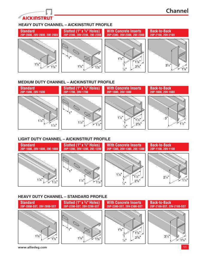
Standard20P-2000, 20V-2000, 20E-2000
Slotted (1" x 3⁄8" Holes)20P-2200, 20V-2200, 20E-2200
With Concrete Inserts20P-2300, 20V-2300, 20E-2300
Back-to-Back20P-2100, 20V-2100
Standard20P-1500, 20V-1500
Slotted (1" x 3⁄8" Holes)20P-1700, 20V-1700
With Concrete Inserts20P-1800, 20V-1800
Back-to-Back20P-1600, 20V-1600
Standard20P-1000, 20V-1000, 20E-1000
Slotted (1" x 3⁄8" Holes)20P-1200, 20V-1200, 20E-1200
With Concrete Inserts20P-1300, 20V-1300, 20E-1300
Back-to-Back20P-1100, 20V-1100
Standard20P-2000-SST, 20V-2000-SST
Slotted (1" x 3⁄8" Holes)20P-2200-SST, 20V-2200-SST
With Concrete Inserts20P-2300-SST, 20V-2300-SST
Back-to-Back20P-2100-SST, 20V-2100-SST
HEAVY DUTY CHANNEL – AICKINSTRUT PROFILE
MEDIUM DUTY CHANNEL – AICKINSTRUT PROFILE
LIGHT DUTY CHANNEL – AICKINSTRUT PROFILE
HEAVY DUTY CHANNEL – STANDARD PROFILE
Channel
12 Aickinstrut
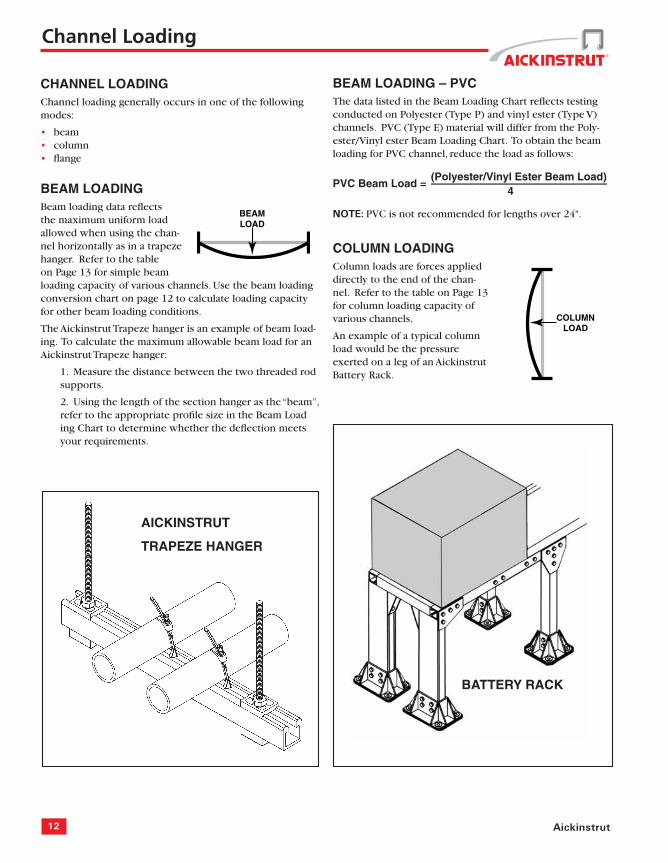
BEAMLOAD
COLUMNLOAD
AICKINSTRUT
TRAPEZE HANGER
BATTERY RACK
CHANNEL LOADINGChannel loading generally occurs in one of the following modes:
beamcolumnfl ange
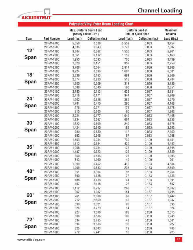
BEAM LOADING Beam loading data refl ects the maximum uniform load allowed when using the chan-nel horizontally as in a trapeze hanger. Refer to the table on Page 13 for simple beam loading capacity of various channels. Use the beam loading conversion chart on page 12 to calculate loading capacity for other beam loading conditions.
The Aickinstrut Trapeze hanger is an example of beam load-ing. To calculate the maximum allowable beam load for an Aickinstrut Trapeze hanger:
1. Measure the distance between the two threaded rod supports.
2. Using the length of the section hanger as the “beam”, refer to the appropriate profi le size in the Beam Load ing Chart to determine whether the defl ection meets your requirements.
•••
BEAM LOADING – PVCThe data listed in the Beam Loading Chart refl ects testing conducted on Polyester (Type P) and vinyl ester (Type V) channels. PVC (Type E) material will differ from the Poly-ester/Vinyl ester Beam Loading Chart. To obtain the beam loading for PVC channel, reduce the load as follows:
NOTE: PVC is not recommended for lengths over 24".
COLUMN LOADINGColumn loads are forces applied directly to the end of the chan-nel. Refer to the table on Page 13 for column loading capacity of various channels.
An example of a typical column load would be the pressure exerted on a leg of an Aickinstrut Battery Rack.
Channel Loading
13www.alliedeg.com
FLANGELOAD
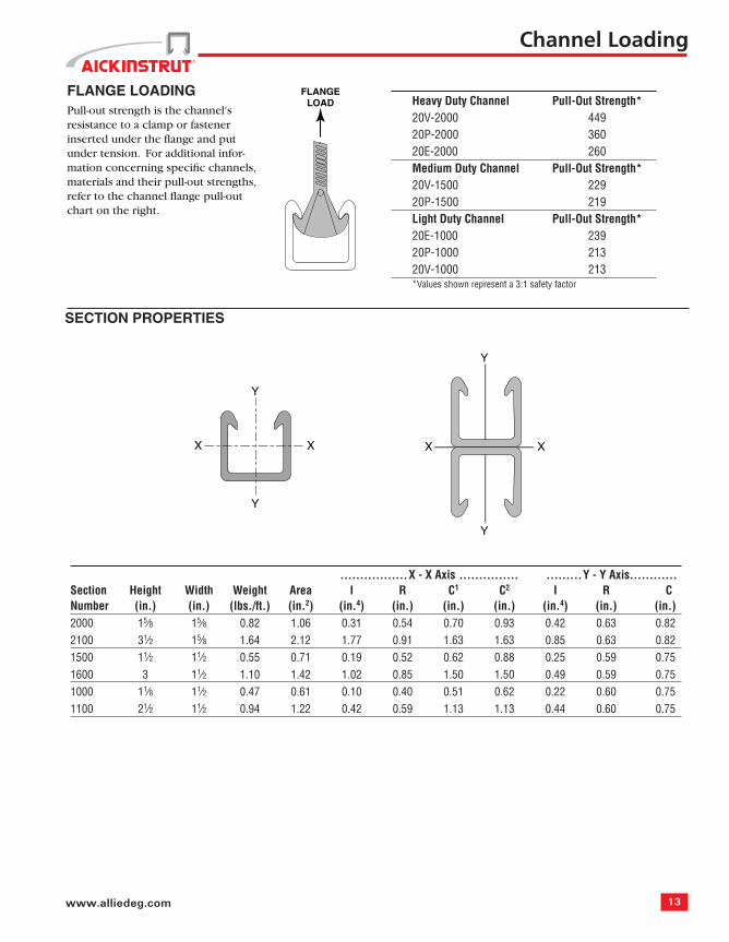
FLANGE LOADINGPull-out strength is the channel's resistance to a clamp or fastener inserted under the fl ange and put under tension. For additional infor-mation concerning specifi c channels, materials and their pull-out strengths, refer to the channel fl ange pull-out chart on the right.
Channel Loading
Heavy Duty Channel Pull-Out Strength*20V-2000 44920P-2000 36020E-2000 260 Medium Duty Channel Pull-Out Strength*20V-1500 22920P-1500 219 Light Duty Channel Pull-Out Strength*20E-1000 23920P-1000 21320V-1000 213 *Values shown represent a 3:1 safety factor
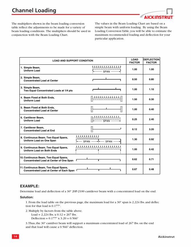
The multipliers shown in the beam loading conversion table refl ect the adjustments to be made for a variety of beam loading conditions. The multipliers should be used in conjunction with the Beam Loading Chart.
Continuous Beam, Two Equal Spans,Concentrated Load at Center of Each Span 0.67 0.48
DEFLECTIONFACTOR
LOADFACTOR
LOAD AND SUPPORT CONDITION
SPAN
SPAN
1.00
1.00
0.50
0.25
1.50
1.00
1.00
0.12
1.30
0.62
1.10
1.00
0.80
2.40
0.30
0.40
0.42
3.20
0.92
0.71
1. Simple Beam,Uniform Load
2. Simple Beam,Concentrated Load at Center
3. Simple Beam,Two Equal Concentrated Loads at 1/4 pts
4. Beam Fixed at Both Ends,Uniform Load
5. Beam Fixed at Both Ends,Concentrated Load at Center
6. Cantilever Beam,Uniform Load
7. Cantilever Beam,Concentrated Load at End
8. Continuous Beam, Two Equal Spans,Uniform Load on One Span
9. Continuous Beam, Two Equal Spans,Uniform Load on Both Ends
10. Continuous Beam, Two Equal Spans,Concentrated Load at Center of One Span
11.
SPAN SPAN
EXAMPLE:Determine load and defl ection of a 30" 20P-2100 cantilever beam with a concentrated load on the end.
Solution:
1. From the load table on the previous page, the maximum load for a 30" span is 2,224 lbs. and defl ec tion for that load is 0.177".
2. Multiply by factors from the table above. Load = 2,224 lbs. x 0.12 = 267 lbs. Defl ection = 0.177" x 3.20 = 0.566"
3. Thus, the 30" cantilver beam will support a maximum concentrated load of 267 lbs. on the end and that load will cause a 0.566" defl ection.
Channel Loading
The values in the Beam Loading Chart are based on a simple beam with uniform loading. By using the Beam Loading Conversion Table, you will be able to estimate the maximum recommended loading and defl ection for your particular application.
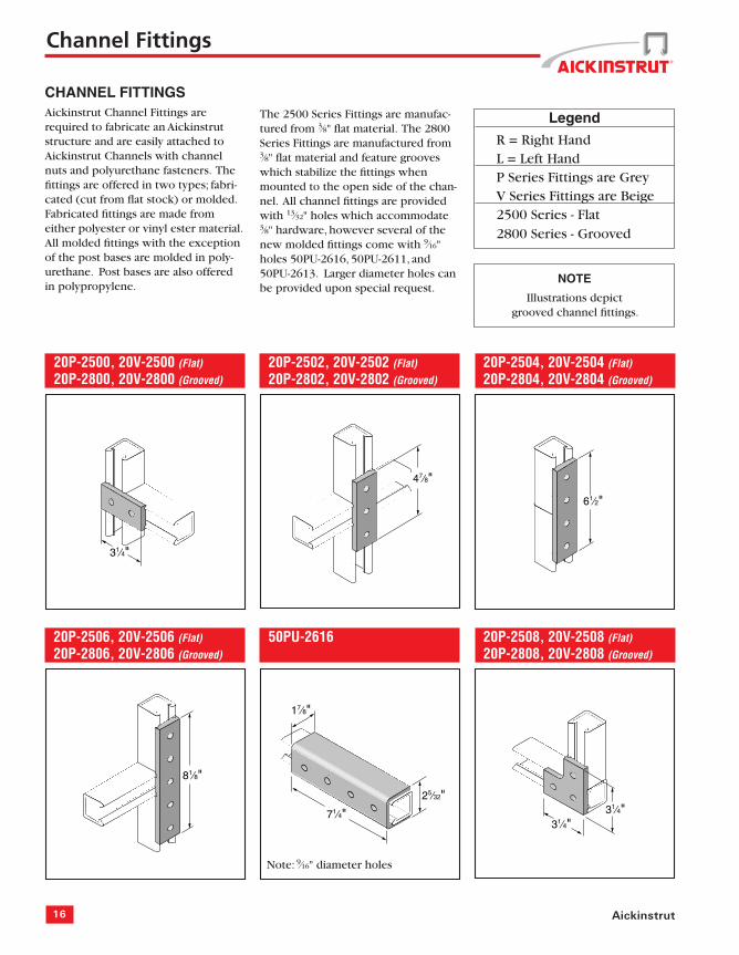
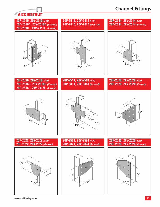
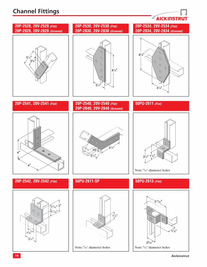
CHANNEL FITTINGSAickinstrut Channel Fittings are required to fabricate an Aickinstrut structure and are easily attached to Aickinstrut Channels with channel nuts and polyurethane fasteners. The fi ttings are offered in two types; fabri-cated (cut from fl at stock) or molded. Fabricated fi ttings are made from either polyester or vinyl ester material. All molded fi ttings with the exception of the post bases are molded in poly-urethane. Post bases are also offered in polypropylene.
The 2500 Series Fittings are manufac-tured from 3⁄8" fl at material. The 2800 Series Fittings are manufactured from 3⁄8" fl at material and feature grooves which stabilize the fi ttings when mounted to the open side of the chan-nel. All channel fi ttings are provided with 13⁄32" holes which accommodate 3⁄8" hardware, however several of the new molded fi ttings come with 9⁄16"holes 50PU-2616, 50PU-2611, and 50PU-2613. Larger diameter holes can be provided upon special request.
Legend
R = Right Hand L = Left Hand P Series Fittings are Grey V Series Fittings are Beige 2500 Series - Flat 2800 Series - Grooved
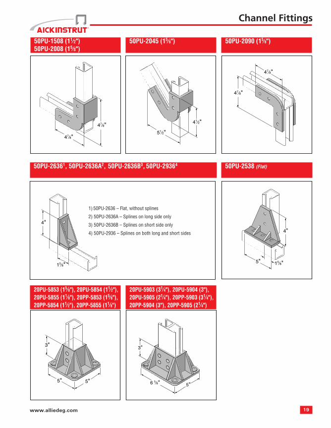
4) 50PU-2936 – Splines on both long and short sides
20 Aickinstrut
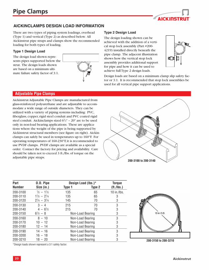
Adjustable Pipe ClampsAickinstrut Adjustable Pipe Clamps are manufactured from glass-reinforced polyurethane and are adjustable to accom-modate a wide range of outside diameters. They can be utilized with a variety of piping systems including: PVC, fi berglass, copper, rigid steel conduit and PVC coated rigid steel conduit. Aickinclamps sized 61⁄2" – 20" are to be used only in non-load bearing applications. These are applica-tions where the weight of the pipe is being supported by Aickinstrut structural members (see fi gure on right). Aickin-clamps can safely be used in temperatures up to 160°F. For operating temperatures of 160-230°F, it is recommended to use PVDF clamps. PVDF clamps are available as a special order. Contact the factory for pricing and availability. Care should be taken not to exceed 3 ft./lbs. of torque on the adjustable pipe straps.
The design loading shown can be achieved with the addition of a verti-cal stop lock assembly (Part #200-4219) installed directly beneath the pipe clamp. The adjacent illustration shows how the vertical stop lock assembly provides additional support for pipe and how it can be used to achieve full Type 2 design loads.
Design loads are based on a minimum clamp slip safety fac-tor or 3:1. It is recommended that stop lock assemblies be used for all vertical pipe support applications.
There are two types of piping system loadings, overhead (Type 1) and vertical (Type 2) as described below. All Aickinstrut pipe straps and clamps show the recommended loading for both types of loading.
Type 1 Design Load
The design load shown repre-sents pipes supported below the strut. The design loads shown are based on a minimum ulti-mate failure safety factor of 3:1.
Pipe Clamps
200-3100 to 200-3140
200-3150 to 200-3210
21www.alliedeg.com
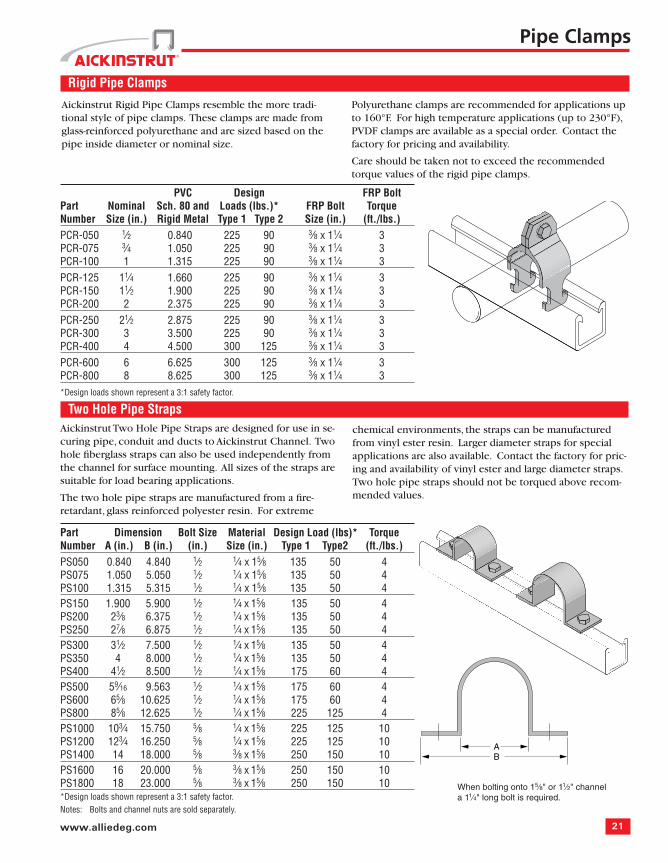
Rigid Pipe Clamps
PVC Design FRP BoltPart Nominal Sch. 80 and Loads (lbs.)* FRP Bolt Torque Number Size (in.) Rigid Metal Type 1 Type 2 Size (in.) (ft./lbs.)PCR-050 1⁄2 0.840 225 90 3⁄8 x 11⁄4 3PCR-075 3⁄4 1.050 225 90 3⁄8 x 11⁄4 3PCR-100 1 1.315 225 90 3⁄8 x 11⁄4 3PCR-125 11⁄4 1.660 225 90 3⁄8 x 11⁄4 3PCR-150 11⁄2 1.900 225 90 3⁄8 x 11⁄4 3PCR-200 2 2.375 225 90 3⁄8 x 11⁄4 3PCR-250 21⁄2 2.875 225 90 3⁄8 x 11⁄4 3PCR-300 3 3.500 225 90 3⁄8 x 11⁄4 3PCR-400 4 4.500 300 125 3⁄8 x 11⁄4 3PCR-600 6 6.625 300 125 3⁄8 x 11⁄4 3PCR-800 8 8.625 300 125 3⁄8 x 11⁄4 3*Design loads shown represent a 3:1 safety factor.
Pipe Clamps
Two Hole Pipe StrapsAickinstrut Two Hole Pipe Straps are designed for use in se-curing pipe, conduit and ducts to Aickinstrut Channel. Two hole fi berglass straps can also be used independently from the channel for surface mounting. All sizes of the straps are suitable for load bearing applications.
The two hole pipe straps are manufactured from a fi re-retardant, glass reinforced polyester resin. For extreme
Part Dimension Bolt Size Material Design Load (lbs)* TorqueNumber A (in.) B (in.) (in.) Size (in.) Type 1 Type2 (ft./lbs.)PS050 0.840 4.840 1⁄2 1⁄4 x 15⁄8 135 50 4PS075 1.050 5.050 1⁄2 1⁄4 x 15⁄8 135 50 4PS100 1.315 5.315 1⁄2 1⁄4 x 15⁄8 135 50 4PS150 1.900 5.900 1⁄2 1⁄4 x 15⁄8 135 50 4PS200 23⁄8 6.375 1⁄2 1⁄4 x 15⁄8 135 50 4PS250 27⁄8 6.875 1⁄2 1⁄4 x 15⁄8 135 50 4PS300 31⁄2 7.500 1⁄2 1⁄4 x 15⁄8 135 50 4PS350 4 8.000 1⁄2 1⁄4 x 15⁄8 135 50 4PS400 41⁄2 8.500 1⁄2 1⁄4 x 15⁄8 175 60 4PS500 59⁄16 9.563 1⁄2 1⁄4 x 15⁄8 175 60 4PS600 65⁄8 10.625 1⁄2 1⁄4 x 15⁄8 175 60 4PS800 85⁄8 12.625 1⁄2 1⁄4 x 15⁄8 225 125 4PS1000 103⁄4 15.750 5⁄8 1⁄4 x 15⁄8 225 125 10PS1200 123⁄4 16.250 5⁄8 1⁄4 x 15⁄8 225 125 10PS1400 14 18.000 5⁄8 3⁄8 x 15⁄8 250 150 10PS1600 16 20.000 5⁄8 3⁄8 x 15⁄8 250 150 10PS1800 18 23.000 5⁄8 3⁄8 x 15⁄8 250 150 10*Design loads shown represent a 3:1 safety factor.Notes: Bolts and channel nuts are sold separately.
Aickinstrut Rigid Pipe Clamps resemble the more tradi-tional style of pipe clamps. These clamps are made from glass-reinforced polyurethane and are sized based on the pipe inside diameter or nominal size.
Polyurethane clamps are recommended for applications up to 160°F. For high temperature applications (up to 230°F), PVDF clamps are available as a special order. Contact the factory for pricing and availability.
Care should be taken not to exceed the recommended torque values of the rigid pipe clamps.
chemical environments, the straps can be manufactured from vinyl ester resin. Larger diameter straps for special applications are also available. Contact the factory for pric-ing and availability of vinyl ester and large diameter straps. Two hole pipe straps should not be torqued above recom-mended values.
When bolting onto 15⁄8" or 11⁄2" channel a 11⁄4" long bolt is required.
AB
22 Aickinstrut
Pipe Clamps
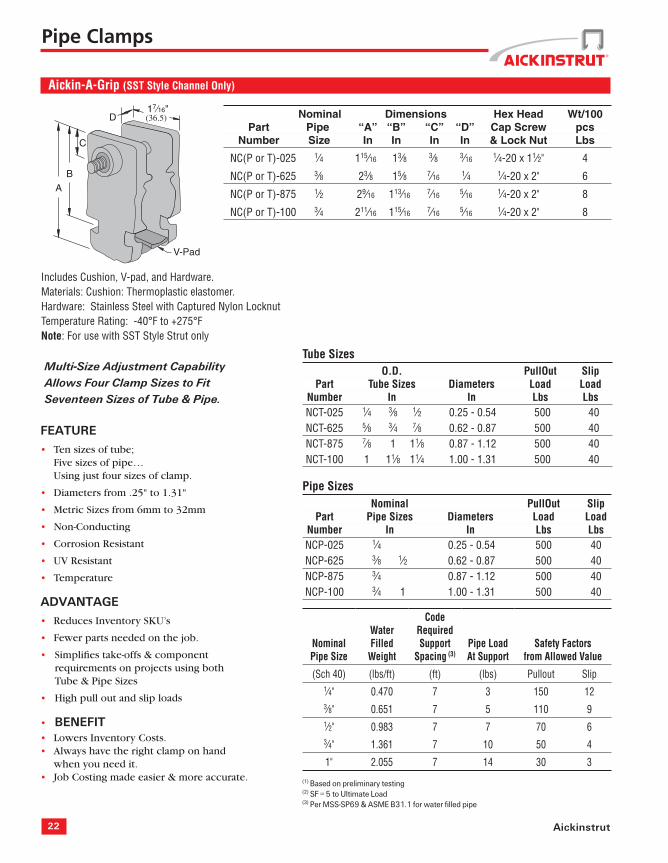
Includes Cushion, V-pad, and Hardware.Materials: Cushion: Thermoplastic elastomer.Hardware: Stainless Steel with Captured Nylon LocknutTemperature Rating: -40°F to +275°FNote: For use with SST Style Strut only
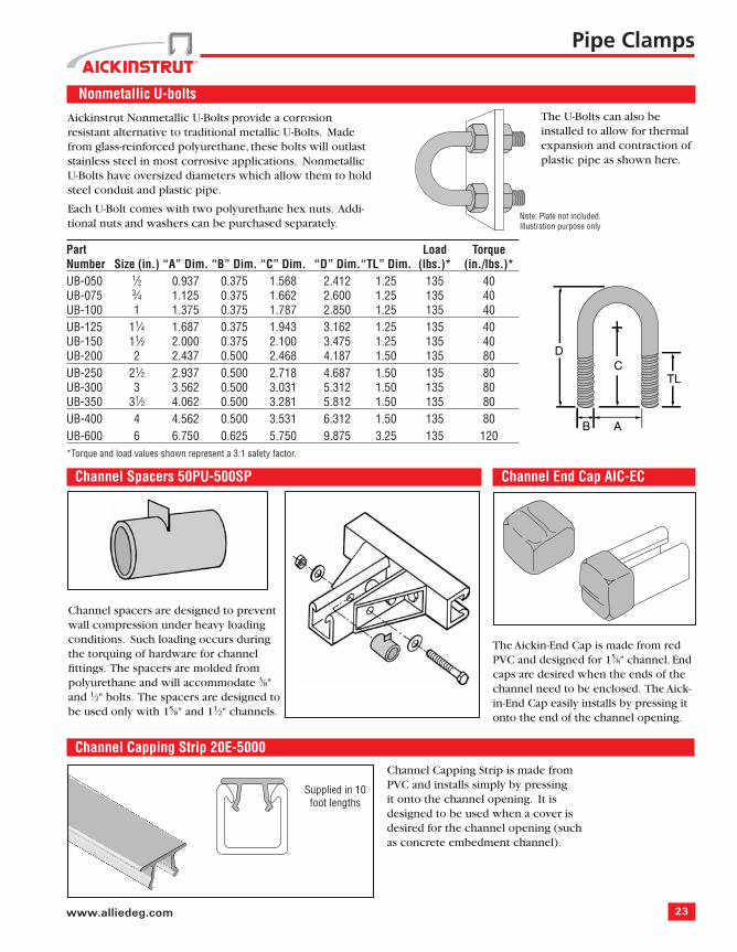
Aickinstrut Nonmetallic U-Bolts provide a corrosion resistant alternative to traditional metallic U-Bolts. Made from glass-reinforced polyurethane, these bolts will outlast stainless steel in most corrosive applications. Nonmetallic U-Bolts have oversized diameters which allow them to hold steel conduit and plastic pipe.
Each U-Bolt comes with two polyurethane hex nuts. Addi-tional nuts and washers can be purchased separately.
C
B A
TL
D
Pipe Clamps
The U-Bolts can also be installed to allow for thermal expansion and contraction of plastic pipe as shown here.
Note: Plate not included. Illustration purpose only
Channel Spacers 50PU-500SP
Supplied in 10 foot lengths
Channel spacers are designed to prevent wall compression under heavy loading conditions. Such loading occurs during the torquing of hardware for channel fi ttings. The spacers are molded from polyurethane and will accommodate 3⁄8"and 1⁄2" bolts. The spacers are designed to be used only with 15⁄8" and 11⁄2" channels.
Channel Capping Strip 20E-5000
Channel End Cap AIC-EC
The Aickin-End Cap is made from red PVC and designed for 15⁄8" channel. End caps are desired when the ends of the channel need to be enclosed. The Aick-in-End Cap easily installs by pressing it onto the end of the channel opening.
Channel Capping Strip is made from PVC and installs simply by pressing it onto the channel opening. It is designed to be used when a cover is desired for the channel opening (such as concrete embedment channel).
24 Aickinstrut
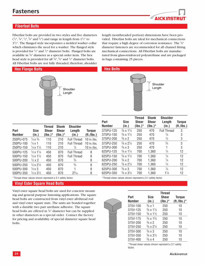
Hex Flange Bolts Hex Bolts
Thread Shank Shoulder Part Size Shear Shear Length TorqueNumber (in.) (lbs.)* (lbs.)* (in.) (ft./lbs.)250PU-075 1⁄4 x 3⁄4 110 210 Full Thread 10 In./lbs.250PU-100 1⁄4 x 1 110 210 Full Thread 10 In./lbs.250PU-150 1⁄4 x 11⁄2 110 210 1⁄2 10 In./lbs.
500PU-125 1⁄2 x 11⁄4 450 870 Full Thread 8500PU-150 1⁄2 x 11⁄2 450 870 Full Thread 8500PU-200 1⁄2 x 2 450 870 3⁄4 8500PU-250 1⁄2 x 21⁄2 450 870 3⁄4 8500PU-300 1⁄2 x 3 450 870 1 8500PU-350 1⁄2 x 31⁄2 450 870 23⁄16 8*Thread shear values shown represent a 3:1 safety factor.
Thread Shank Shoulder Part Size Shear Shear Length TorqueNumber (in.) (lbs.)* (lbs.)* (in.) (ft./lbs.)375PU-125 3⁄8 x 11⁄4 250 470 Full Thread 3375PU-150 3⁄8 x 11⁄2 250 470 1⁄4 3375PU-200 3⁄8 x 2 250 470 1⁄2 3375PU-250 3⁄8 x 21⁄2 250 470 3⁄4 3375PU-300 3⁄8 x 3 250 470 1 3625PU-125 5⁄8 x 11⁄4 700 1,360 1⁄4 12625PU-150 5⁄8 x 11⁄2 700 1,360 1⁄4 12625PU-200 5⁄8 x 2 700 1,360 1⁄4 12625PU-250 5⁄8 x 21⁄2 700 1,360 1⁄4 12625PU-300 5⁄8 x 3 700 1,360 1⁄4 12625PU-350 5⁄8 x 31⁄2 700 1,360 11⁄4 12*Thread shear values shown represent a 3:1 safety factor.
Vinyl Ester Square Head Bolts
Vinyl ester square head bolts are used for concrete mount-ing and general purpose fastening applications. The square head bolts are constructed from vinyl ester all-thread rod and vinyl ester square nuts. The units are bonded together with a durable two part urethane adhesive. The square head bolts are offered in 3⁄8" diameter but can be supplied in other diameters as a special order. Contact the factory for pricing and availability of special diameter square head bolts.
Thread Part Size Shear TorqueNumber (in.) (lbs.)* (ft./lbs.)*375V-100 3⁄8 x 1 250 10375V-125 3⁄8 x 11⁄4 250 10375V-150 3⁄8 x 11⁄2 250 10375V-175 3⁄8 x 13⁄4 250 10375V-200 3⁄8 x 2 250 10375V-250 3⁄8 x 21⁄2 250 10375V-300 3⁄8 x 3 250 10375V-350 3⁄8 x 31⁄2 250 10375V-400 3⁄8 x 4 250 10*Thread shear values shown represent a 3:1 safety factor.
ShoulderLengthShoulder
Length
Fasteners
Fiberfast Bolts
Fiberfast bolts are provided in two styles and fi ve diameters (1⁄4", 3⁄8", 1⁄2", 5⁄8" and 3⁄4") and range in length from 11⁄4" to 31⁄2". The fl anged style incorporates a molded washer collar which eliminates the need for a washer. The fl anged style is provided for 1⁄4" and 1⁄2" diameter bolts. Flanged bolts are available in 3⁄8" diameter as a special order item. The hex head style is provided for all 3⁄8", 5⁄8" and 3⁄4" diameter bolts. All Fiberfast bolts are not fully threaded, therefore, shoulder
length (nonthreaded portion) dimensions have been pro-vided. Fiberfast bolts are ideal for mechanical connections that require a high degree of corrosion resistance. The 3⁄8"diameter fasteners are recommended for all channel fi tting mechanical connections. All Fiberfast bolts are manufac-tured from glass-reinforced polyurethane and are packaged in bags containing 25 pieces.
25www.alliedeg.com
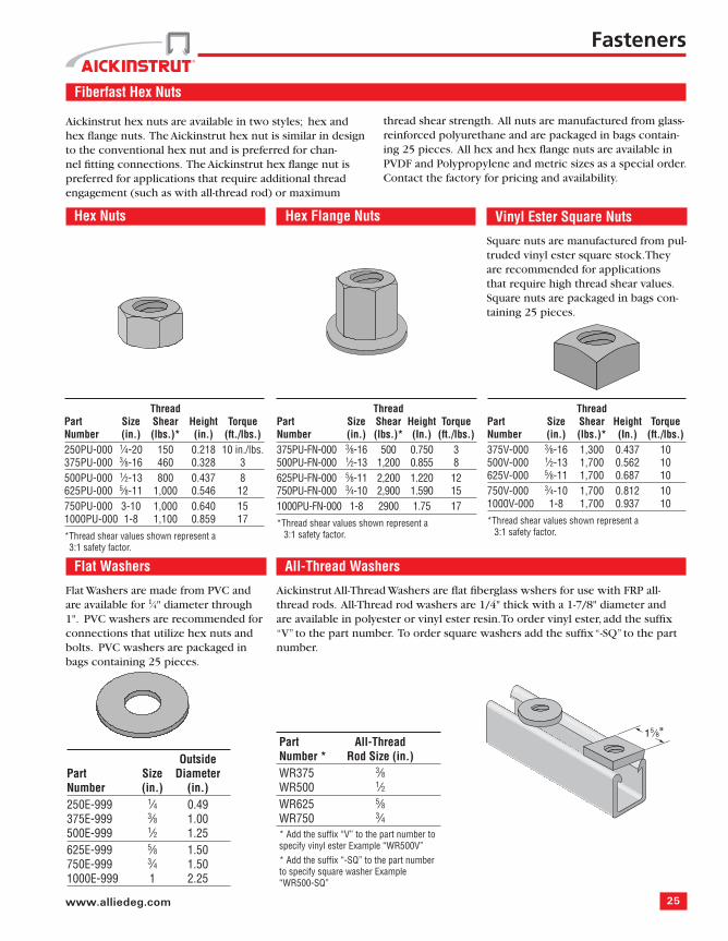
Vinyl Ester Square Nuts
Square nuts are manufactured from pul-truded vinyl ester square stock. They are recommended for applications that require high thread shear values. Square nuts are packaged in bags con-taining 25 pieces.
Flat Washers
Flat Washers are made from PVC and are available for 1⁄4" diameter through 1". PVC washers are recommended for connections that utilize hex nuts and bolts. PVC washers are packaged in bags containing 25 pieces.
Aickinstrut hex nuts are available in two styles; hex and hex fl ange nuts. The Aickinstrut hex nut is similar in design to the conventional hex nut and is preferred for chan-nel fi tting connections. The Aickinstrut hex fl ange nut is preferred for applications that require additional thread engagement (such as with all-thread rod) or maximum
thread shear strength. All nuts are manufactured from glass-reinforced polyurethane and are packaged in bags contain-ing 25 pieces. All hex and hex fl ange nuts are available in PVDF and Polypropylene and metric sizes as a special order. Contact the factory for pricing and availability.
Aickinstrut All-Thread Washers are fl at fi berglass wshers for use with FRP all-thread rods. All-Thread rod washers are 1/4" thick with a 1-7/8" diameter and are available in polyester or vinyl ester resin. To order vinyl ester, add the suffi x “V” to the part number. To order square washers add the suffi x “-SQ” to the part number.
Part All-ThreadNumber * Rod Size (in.)WR375 3⁄8WR500 1⁄2WR625 5⁄8WR750 3⁄4* Add the suffi x “V” to the part number to specify vinyl ester Example “WR500V”* Add the suffi x “-SQ” to the part number to specify square washer Example “WR500-SQ”
15⁄8"
26 Aickinstrut
Fasteners
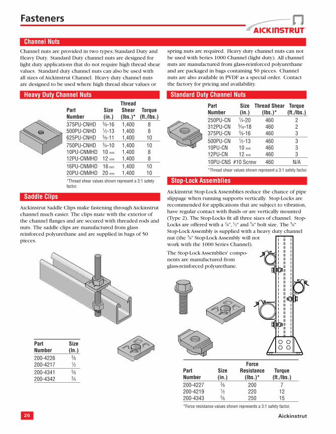
Channel NutsChannel nuts are provided in two types; Standard Duty and Heavy Duty. Standard Duty channel nuts are designed for light duty applications that do not require high thread shear values. Standard duty channel nuts can also be used with all sizes of Aickinstrut Channel. Heavy duty channel nuts are designed to be used where high thread shear values or
spring nuts are required. Heavy duty channel nuts can not be used with Series 1000 Channel (light duty). All channel nuts are manufactured from glass-reinforced polyurethane and are packaged in bags containing 50 pieces. Channel nuts are also available in PVDF as a special order. Contact the factory for pricing and availability.
Standard Duty Channel NutsHeavy Duty Channel Nuts
Part Size Thread Shear TorqueNumber (in.) (lbs.)* (ft./lbs.)250PU-CN 1⁄4-20 460 2312PU-CN 5⁄16-18 460 2375PU-CN 3⁄8-16 460 3500PU-CN 1⁄2-13 460 310PU-CN 10 mm 460 312PU-CN 12 mm 460 310PU-CNS #10 Screw 460 N/A*Thread shear values shown represent a 3:1 safety factor.
Thread Part Size Shear TorqueNumber (in.) (lbs.)* (ft./lbs.)375PU-CNHD 3⁄8-16 1,400 8500PU-CNHD 1⁄2-13 1,400 8625PU-CNHD 5⁄8-11 1,400 10750PU-CNHD 3⁄4-10 1,400 1010PU-CNMHD 10 mm 1,400 812PU-CNMHD 12 mm 1,400 816PU-CNMHD 16 mm 1,400 1020PU-CNMHD 20 mm 1,400 10*Thread shear values shown represent a 3:1 safety factor.
Part SizeNumber (In.)200-4226 3⁄8200-4217 1⁄2200-4341 5⁄8200-4342 3⁄4
Stop-Lock Assemblies
Aickinstrut Stop-Lock Assemblies reduce the chance of pipe slippage when running supports vertically. Stop-Locks are recommended for applications that are subject to vibration, have regular contact with fl uids or are vertically mounted (Type 2). The Stop-Locks fi t all three sizes of channel. Stop-Locks are offered with a 3⁄8", 1⁄2" and 5⁄8" bolt size. The 5⁄8"Stop-Lock Assembly is supplied with a heavy duty channel nut (the 5⁄8" Stop-Lock Assembly will not work with the 1000 Series Channel).
The Stop-Lock Assemblies' compo-nents are manufactured from glass-reinforced polyurethane.
Saddle Clips
Aickinstrut Saddle Clips make fastening through Aickinstrut channel much easier. The clips mate with the exterior of the channel fl anges and are secured with threaded rods and nuts. The saddle clips are manufactured from glass reinforced polyurethane and are supplied in bags of 50 pieces.
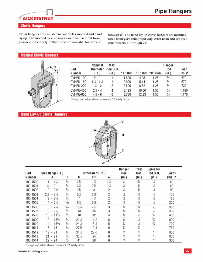
Clevis hangers are available in two styles; molded and hand lay-up. The molded clevis hangers are manufactured from glass-reinforced polyurethane and are available for sizes 1⁄2"
through 6". The hand lay-up clevis hangers are manufac-tured from glass-reinforced vinyl ester resin and are avail-able for sizes 1" through 24".
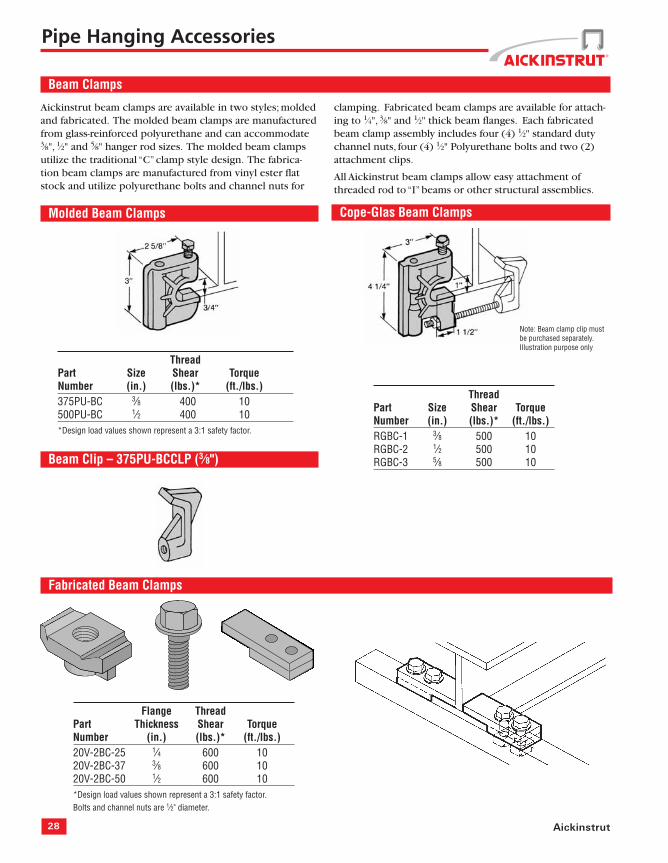
Aickinstrut beam clamps are available in two styles; molded and fabricated. The molded beam clamps are manufactured from glass-reinforced polyurethane and can accommodate 3⁄8", 1⁄2" and 5⁄8" hanger rod sizes. The molded beam clamps utilize the traditional “C” clamp style design. The fabrica-tion beam clamps are manufactured from vinyl ester fl at stock and utilize polyurethane bolts and channel nuts for
clamping. Fabricated beam clamps are available for attach-ing to 1⁄4", 3⁄8" and 1⁄2" thick beam fl anges. Each fabricated beam clamp assembly includes four (4) 1⁄2" standard duty channel nuts, four (4) 1⁄2" Polyurethane bolts and two (2) attachment clips.
All Aickinstrut beam clamps allow easy attachment of threaded rod to “I” beams or other structural assemblies.
Flange Thread Part Thickness Shear TorqueNumber (in.) (lbs.)* (ft./lbs.)20V-2BC-25 1⁄4 600 1020V-2BC-37 3⁄8 600 1020V-2BC-50 1⁄2 600 10*Design load values shown represent a 3:1 safety factor. Bolts and channel nuts are 1⁄2" diameter.
Pipe Hanging Accessories
Note: Beam clamp clip must be purchased separately. Illustration purpose only
29www.alliedeg.com
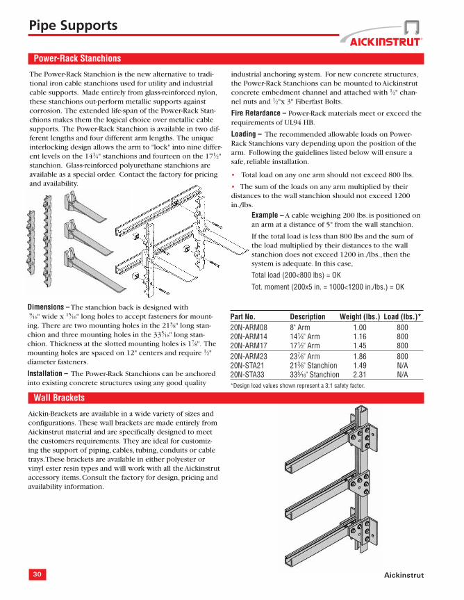
Duraclamp C-Clamps
Duraclamps are glass-reinforced polyurethane C-Clamps that are designed to replace steel C-Clamps in areas where corrosion is a problem. The individual Duraclamp compo-nents can also be purchased separately.
ThreadPart Shear TorqueNumber Description (lbs.)* (ft./lbs.)390N-150 “C”-Clamp 25 17390N-BLT Bolt N/A 17390N-CLP “C” 25 N/A*Design load values shown represent a 3:1 safety factor.Note: Bolt Dimension is 5⁄8" x 21⁄2"
Pipe Supports
Threaded Rod
Pultruded threaded rods are an excellent choice for hang-ing and fastening Aickinstrut Channel. These rods can also be used with either the Aickinstrut vinyl ester square nuts, polyurethane hex nuts, hex fl ange nuts and Aickinstrut channel nuts. All FRP threaded rod is manufactured from pultruded vinyl ester resin and is gray in color.
The standard rod lengths are 4' and 8'. Special lengths and threading are also available. Contact the factory for pricing and availability.
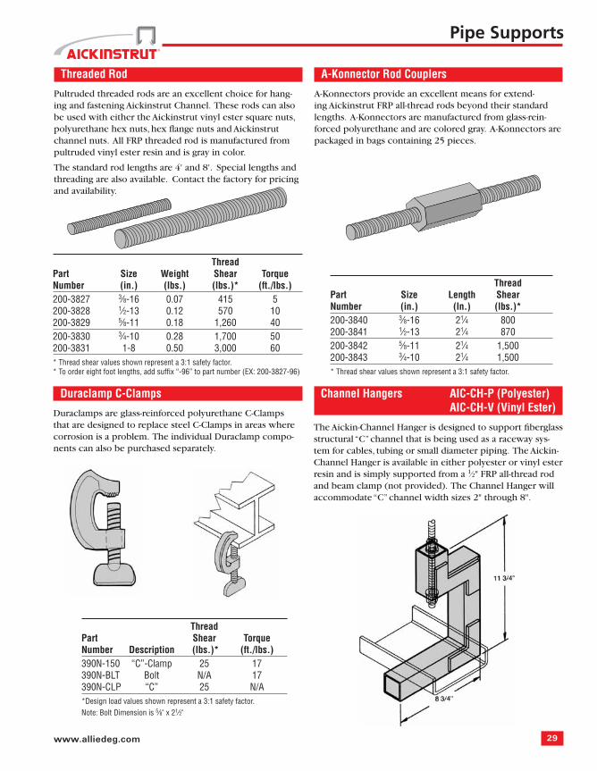
A-Konnector Rod Couplers
A-Konnectors provide an excellent means for extend-ing Aickinstrut FRP all-thread rods beyond their standard lengths. A-Konnectors are manufactured from glass-rein-forced polyurethane and are colored gray. A-Konnectors are packaged in bags containing 25 pieces.
Thread Part Size Weight Shear TorqueNumber (in.) (lbs.) (lbs.)* (ft./lbs.)200-3827 3⁄8-16 0.07 415 5200-3828 1⁄2-13 0.12 570 10200-3829 5⁄8-11 0.18 1,260 40200-3830 3⁄4-10 0.28 1,700 50200-3831 1-8 0.50 3,000 60* Thread shear values shown represent a 3:1 safety factor.* To order eight foot lengths, add suffi x “-96” to part number (EX: 200-3827-96)
The Aickin-Channel Hanger is designed to support fi berglass structural “C” channel that is being used as a raceway sys-tem for cables, tubing or small diameter piping. The Aickin-Channel Hanger is available in either polyester or vinyl ester resin and is simply supported from a 1⁄2" FRP all-thread rod and beam clamp (not provided). The Channel Hanger will accommodate “C” channel width sizes 2" through 8".
30 Aickinstrut
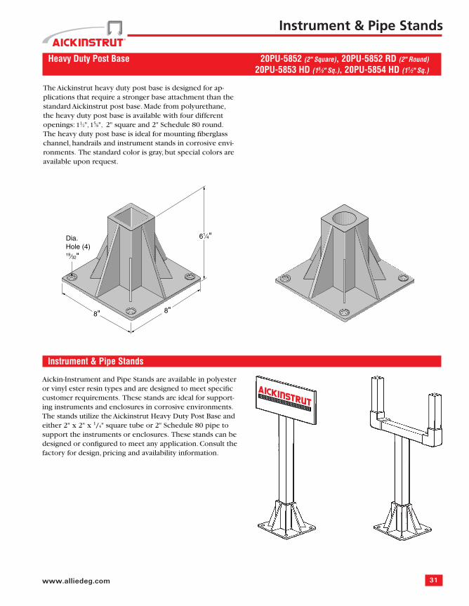
Power-Rack Stanchions
The Power-Rack Stanchion is the new alternative to tradi-tional iron cable stanchions used for utility and industrial cable supports. Made entirely from glass-reinforced nylon, these stanchions out-perform metallic supports against corrosion. The extended life-span of the Power-Rack Stan-chions makes them the logical choice over metallic cable supports. The Power-Rack Stanchion is available in two dif-ferent lengths and four different arm lengths. The unique interlocking design allows the arm to "lock" into nine differ-ent levels on the 141⁄4" stanchions and fourteen on the 171⁄2"stanchion. Glass-reinforced polyurethane stanchions are available as a special order. Contact the factory for pricing and availability.
Part No. Description Weight (lbs.) Load (lbs.)*20N-ARM08 8" Arm 1.00 80020N-ARM14 141⁄4" Arm 1.16 80020N-ARM17 171⁄2" Arm 1.45 80020N-ARM23 237⁄8" Arm 1.86 80020N-STA21 213⁄8" Stanchion 1.49 N/A20N-STA33 335⁄16" Stanchion 2.31 N/A*Design load values shown represent a 3:1 safety factor.
industrial anchoring system. For new concrete structures, the Power-Rack Stanchions can be mounted to Aickinstrut concrete embedment channel and attached with 1⁄2" chan-nel nuts and 1⁄2"x 3" Fiberfast Bolts.
Fire Retardance – Power-Rack materials meet or exceed the requirements of UL94 HB.
Loading – The recommended allowable loads on Power-Rack Stanchions vary depending upon the position of the arm. Following the guidelines listed below will ensure a safe, reliable installation.
Total load on any one arm should not exceed 800 lbs.
The sum of the loads on any arm multiplied by their distances to the wall stanchion should not exceed 1200 in./lbs.
Example – A cable weighing 200 lbs. is positioned on an arm at a distance of 5" from the wall stanchion.
If the total load is less than 800 lbs and the sum of the load multiplied by their distances to the wall stanchion does not exceed 1200 in./lbs., then the system is adequate. In this case,
Total load (200<800 lbs) = OK
Tot. moment (200x5 in. = 1000<1200 in./lbs.) = OK
•
•
Dimensions – The stanchion back is designed with9⁄16" wide x 15⁄16" long holes to accept fasteners for mount-ing. There are two mounting holes in the 213⁄8" long stan-chion and three mounting holes in the 335⁄16" long stan-chion. Thickness at the slotted mounting holes is 17⁄8". The mounting holes are spaced on 12" centers and require 1⁄2"diameter fasteners.
Installation – The Power-Rack Stanchions can be anchored into existing concrete structures using any good quality
Wall Brackets
Aickin-Brackets are available in a wide variety of sizes and confi gurations. These wall brackets are made entirely from Aickinstrut material and are specifi cally designed to meet the customers requirements. They are ideal for customiz-ing the support of piping, cables, tubing, conduits or cable trays. These brackets are available in either polyester or vinyl ester resin types and will work with all the Aickinstrut accessory items. Consult the factory for design, pricing and availability information.
Pipe Supports
31www.alliedeg.com
Instrument & Pipe Stands
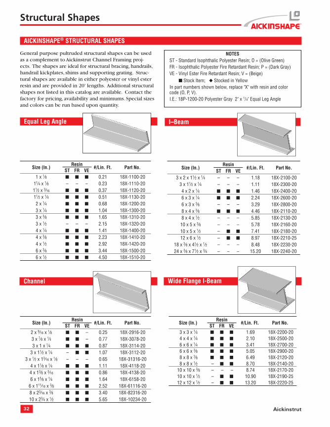
Heavy Duty Post Base 20PU-5852 (2" Square), 20PU-5852 RD (2" Round)
20PU-5853 HD (15⁄8" Sq.), 20PU-5854 HD (11⁄2" Sq.)
The Aickinstrut heavy duty post base is designed for ap-plications that require a stronger base attachment than the standard Aickinstrut post base. Made from polyurethane, the heavy duty post base is available with four different openings: 11⁄2", 15⁄8", 2" square and 2" Schedule 80 round. The heavy duty post base is ideal for mounting fi berglass channel, handrails and instrument stands in corrosive envi-ronments. The standard color is gray, but special colors are available upon request.
8" 8"
Dia.Hole (4)19⁄32"
61⁄4"
Instrument & Pipe Stands
Aickin-Instrument and Pipe Stands are available in polyester or vinyl ester resin types and are designed to meet specifi c customer requirements. These stands are ideal for support-ing instruments and enclosures in corrosive environments. The stands utilize the Aickinstrut Heavy Duty Post Base and either 2" x 2" x 1/4" square tube or 2" Schedule 80 pipe to support the instruments or enclosures. These stands can be designed or confi gured to meet any application. Consult the factory for design, pricing and availability information.
32 Aickinstrut
Channel
AICKINSHAPE® STRUCTURAL SHAPES
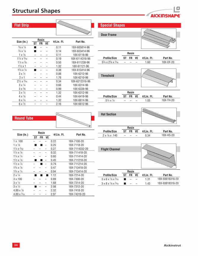
General purpose pultruded structural shapes can be used as a complement to Aickinstrut Channel Framing proj-ects. The shapes are ideal for structural bracing, handrails, handrail kickplates, shims and supporting grating. Struc-tural shapes are available in either polyester or vinyl ester resin and are provided in 20' lengths. Additional structural shapes not listed in this catalog are available. Contact the factory for pricing, availability and minimums. Special sizes and colors can be run based upon quantity.
Equal Leg Angle
NOTESST - Standard Isophthalic Polyester Resin; O = (Olive Green)FR - Isophthalic Polyester Fire Retardant Resin; P = (Dark Gray)VE - Vinyl Ester Fire Retardant Resin; V = (Beige) ■ Stock Item; ◆ Stocked in YellowIn part numbers shown below, replace "X" with resin and color code (O, P, V). I.E.: 18P-1200-20 Polyester Gray 2" x 1/4" Equal Leg Angle
Structural Shapes
I–Beam
Size (In.)Resin
#/Lin. Ft. Part No.ST FR VE
3 x 2 x 11⁄2 x 1⁄4 – – – 1.18 18X-2100-203 x 11⁄2 x 1⁄4 – – – 1.11 18X-2300-204 x 2 x 1⁄4 ■ ■ ■ 1.46 18X-2400-206 x 3 x 1⁄4 ■ ■ ■ 2.24 18X-2600-206 x 3 x 3⁄8 – – – 3.29 18X-2800-208 x 4 x 3⁄8 ■ ■ ■ 4.46 18X-2110-208 x 4 x 1⁄2 – – – 5.85 18X-2130-20
10 x 5 x 3⁄8 – – – 5.78 18X-2160-2010 x 5 x 1⁄2 – ■ ■ 7.41 18X-2180-2012 x 6 x 1⁄2 – ■ ■ 8.97 18X-2210-25
18 x 3⁄8 x 41⁄2 x 1⁄2 – – – 8.48 18X-2230-2024 x 3⁄8 x 71⁄2 x 3⁄4 – – – 15.20 18X-2240-20
Size (In.)Resin
#/Lin. Ft. Part No.ST FR VE
2 x 9⁄16 x 1⁄8 ■ ■ – 0.25 18X-2916-203 x 7⁄8 x 1⁄4 ■ ■ – 0.77 18X-3078-203 x 1 x 1⁄4 ■ ■ ■ 0.87 18X-3114-20
3 x 11⁄2 x 1⁄4 – ■ ■ 1.07 18X-3112-203 x 1⁄2 x 13⁄16 x 1⁄8 – – – 0.65 18X-31316-20
4 x 11⁄8 x 1⁄4 ■ ■ ■ 1.11 18X-4118-204 x 13⁄8 x 3⁄16 ■ ■ ■ 0.86 18X-4138-206 x 15⁄8 x 1⁄4 ■ ■ ■ 1.64 18X-6158-20
6 x 111⁄16 x 3⁄8 ■ ■ ■ 2.52 18X-61116-208 x 23⁄16 x 3⁄8 ■ ■ ■ 3.40 18X-82316-2010 x 23⁄4 x 1⁄2 ■ ■ ■ 5.65 18X-10234-20
Size (In.)Resin
#/Lin. Ft. Part No.ST FR VE
1 x 1⁄8 ■ ■ ■ 0.21 18X-1100-2011⁄4 x 1⁄8 – – – 0.23 18X-1110-2011⁄2 x 3⁄16 ■ ■ ■ 0.37 18X-1120-2011⁄2 x 1⁄4 ■ ■ ■ 0.51 18X-1130-202 x 1⁄4 ■ ■ ■ 0.68 18X-1200-203 x 1⁄4 ■ ■ ■ 1.04 18X-1300-203 x 3⁄8 ■ ■ ■ 1.65 18X-1310-203 x 1⁄2 – – – 2.15 18X-1320-204 x 1⁄4 ■ ■ ■ 1.41 18X-1400-204 x 3⁄8 ■ ■ ■ 2.23 18X-1410-204 x 1⁄2 ■ ■ ■ 2.92 18X-1420-206 x 3⁄8 ■ ■ ■ 3.44 18X-1500-206 x 1⁄2 ■ ■ ■ 4.50 18X-1510-20
Wide Flange I-Beam
Size (In.)Resin
#/Lin. Ft. Part No.ST FR VE
3 x 3 x 1⁄4 ■ ■ ■ 1.69 18X-2200-204 x 4 x 1⁄4 ■ ■ ■ 2.10 18X-2500-206 x 6 x 1⁄4 ■ ■ ■ 3.41 18X-2700-206 x 6 x 3⁄8 ■ ■ ■ 5.05 18X-2900-208 x 8 x 3⁄8 ■ ■ ■ 6.49 18X-2120-208 x 8 x 1⁄2 – ■ ■ 8.70 18X-2140-20
10 x 10 x 3⁄8 – – – 8.74 18X-2170-2010 x 10 x 1⁄2 – ■ ■ 10.90 18X-2190-2512 x 12 x 1⁄2 – ■ ■ 13.20 18X-2220-25
33www.alliedeg.com
Size (In.)Resin
#/Lin. Ft. Part No.ST FR VE
4 x 1 x 1⁄8 – – – 0.85 18X-4118-204 x 1⁄8 x 2 x 1⁄4 ■ ■ ■ 1.52 18X-418214-20
43⁄8 x 13⁄8 x 1⁄8 x 3⁄16 – – – 1.18 18X-438138-2041⁄2 x 13⁄4 x 1⁄8 x 3⁄16 – – – 1.29 18X-412138-20
5 x 2 x 1⁄8 – – – 1.32 18X-5218-2051⁄8 x 21⁄8 x 3⁄16 – – – 1.32 18X-518218-20
61⁄2 x 1⁄4 x 2 x 1⁄2 – – – 3.77 18X-612212-206 x 4 x 1⁄4 – ■ – 18X-6414-20
Structural Shapes
Flat Sheet
Embedment Angle
Size (In.)Resin
#/Lin. Ft. Part No.ST FR VE
1 x 11⁄2 x 1⁄4 – – ■ 1.00 18X-111214-2011⁄2 x 11⁄2 x 1⁄4 – – ■ 1.10 18X-11211214-202 x 11⁄2 x 1⁄4 – – ■ 1.20 18X-211214-20
Square Bar
Size (In.)Resin
#/Lin. Ft. Part No.ST FR VE
1 x 1 ■ – – 0.87 18X-5100-2011⁄4 x 11⁄4 – ◆ – 1.31 18X-5125-2011⁄2 x 11⁄2 – ◆ – 1.98 18X-5150-202 x 2 – – – 3.12 18X-5200-20
Rectangular Tube
Size (In.)Resin
#/Lin. Ft. Part No.ST FR VE
1⁄8 x 48 x 96 ■ ■ ■ 1.14 18X-41003⁄16 x 48 x 96 ■ ■ ■ 1.71 18X-42001⁄4 x 48 x 96 ■ ■ ■ 2.34 18X-43003⁄8 x 48 x 96 ■ ■ ■ 3.54 18X-44001⁄2 x 48 x 96 ■ ■ ■ 4.68 18X-45005⁄8 x 48 x 96 – – – 5.79 18X-46003⁄4 x 48 x 96 – – – 6.94 18X-47001 x 48 x 96 – – – 9.27 18X-4800
Square Tube
Size (In.)Resin
#/Lin. Ft. Part No.ST FR VE
1 x 1⁄8 ■ ■ ■ 0.32 18X-3100-2011⁄8 x 1⁄8 – – – 0.37 18X-3200-2011⁄4 x 1⁄8 – – – 0.41 18X-3300-2011⁄4 x 1⁄4 – – – 0.68 18X-3310-2011⁄2 x 1⁄8 ■ ◆ ◆ 0.54 18X-3400-2011⁄2 x 1⁄4 – – ■ 0.98 18X-3410-2013⁄4 x 1⁄8 – ◆ ◆ 0.63 18X-3500-2013⁄4 x 1⁄4 – ◆ ◆ 1.10 18X-3510-202 x 1⁄8 ■ ◆ ◆ 0.69 18X-3600-202 x 1⁄4 ■ ◆ ◆ 1.40 18X-3610-20
21⁄4 x 1⁄8 – ◆ – 0.83 18X-3800-2021⁄4 x 1⁄4 – – – 1.56 18X-3810-2021⁄2 x 1⁄4 – ◆ – 1.79 18X-3900-203 x 1⁄8 – – – 1.12 18X-3110-203 x 1⁄4 ■ ■ ■ 2.15 18X-3111-204 x 1⁄4 ■ ■ ■ 2.93 18X-3120-204 x 3⁄8 ■ – – 4.24 18X-3121-206 x 3⁄8 ■ ■ ■ 6.42 18X-3140-20
Profi le/Size ST FR VE #/Lin. Ft. Part No.53⁄4 x 25⁄8 x 3⁄16 – – – 1.60 18X-DF-20
Threshold
ResinProfi le/Size ST FR VE #/Lin. Ft. Part No.
51⁄2 x 1⁄4 – – – 1.05 18X-TH-20
Hat Section
ResinProfi le/Size ST FR VE #/Lin. Ft. Part No.2 x 7⁄8 x .140 – – – 0.34 18X-HS-20
Flight Channel
ResinProfi le/Size ST FR VE #/Lin. Ft. Part No.
3 x 6 x 1⁄8 x 3⁄16 ■ – – 1.31 18X-93618316-20
3 x 8 x 1⁄8 x 3⁄16 ■ – – 1.43 18X-93818316-20
Structural Shapes
Flat Strip
Size (In.)Resin
#/Lin. Ft. Part No.ST FR VE
5⁄8 x 1⁄4 ■ – – 0.11 18X-605814-963⁄4 x 1⁄4 ■ – – 0.14 18X-603414-961 x 1⁄8 – – – 0.11 18X-6118-96
11⁄4 x 3⁄16 – – – 0.19 18X-6114316-9611⁄2 x 3⁄8 – – – 0.50 18X-611238-9611⁄2 x 1 – – – 1.32 18X-61121-9613⁄4 x 1⁄4 ■ – – 0.38 18X-613414-962 x 1⁄2 – – – 0.88 18X-6212-962 x 1 – – – 1.76 18X-6210-96
21⁄2 x 3⁄16 – – – 0.34 18X-6212316-963 x 1⁄4 – – – 0.66 18X-6314-963 x 3⁄8 – – – 0.99 18X-6338-963 x 1⁄2 – – – 1.32 18X-6312-964 x 1⁄8 – – – 0.44 18X-6418-966 x 1⁄4 – – – 1.32 18X-6614-966 x 1⁄2 – – – 2.16 18X-6612-96
Size (In.)Resin
#/Lin. Ft. Part No.ST FR VE
1 x .100 – – – 0.22 18X-7100-201 x 1⁄8 ■ ■ – 0.25 18X-7118-2011⁄4 x 3⁄32 – – – 0.27 18X-7114332-2011⁄4 x 1⁄8 – – – 0.32 18X-711418-2011⁄4 x 1⁄4 – – – 0.60 18X-711414-2011⁄2 x 1⁄8 ■ ■ – 0.45 18X-711218-2011⁄2 x 1⁄4 – ■ – 0.79 18X-711214-2013⁄4 x 1⁄8 – – – 0.47 18X-713418-2013⁄4 x 1⁄4 – – – 0.94 18X-713414-202 x 1⁄4 ■ ■ ■ 1.12 18X-7214-203 x.100 – – – 0.89 18X-7300-203 x 1⁄4 – – – 1.68 18X-7314-203 x 1⁄2 ■ – – 2.98 18X-7312-204.89 x 1⁄8 – – – 2.32 18X-7418-204.89 x 3⁄16 – – – 2.97 18X-74316-20
35www.alliedeg.com
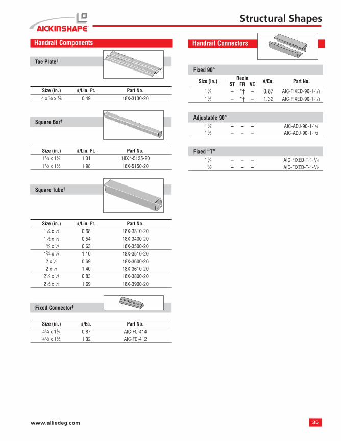
Handrail Components
Toe Plate†
Size (in.) #/Lin. Ft. Part No.4 x 5⁄8 x 1⁄8 0.49 18X-3130-20
Square Bar†
Size (in.) #/Lin. Ft. Part No.11⁄4 x 11⁄4 1.31 18X*-5125-2011⁄2 x 11⁄2 1.98 18X-5150-20
Square Tube†
Size (in.) #/Lin. Ft. Part No.11⁄4 x 1⁄4 0.68 18X-3310-2011⁄2 x 1⁄8 0.54 18X-3400-2013⁄4 x 1⁄8 0.63 18X-3500-2013⁄4 x 1⁄4 1.10 18X-3510-202 x 1⁄8 0.69 18X-3600-202 x 1⁄4 1.40 18X-3610-20
21⁄4 x 1⁄8 0.83 18X-3800-2021⁄2 x 1⁄4 1.69 18X-3900-20
Fixed Connector†
Size (in.) #/Ea. Part No.41⁄4 x 11⁄4 0.87 AIC-FC-41441⁄2 x 11⁄2 1.32 AIC-FC-412
Structural Shapes
Handrail Connectors
Fixed 90°
Size (In.)Resin
#/Ea. Part No.ST FR VE
11⁄4 – *† – 0.87 AIC-FIXED-90-1-1/4
11⁄2 – *† – 1.32 AIC-FIXED-90-1-1/2
Adjustable 90°11⁄4 – – – AIC-ADJ-90-1-1/4
11⁄2 – – – AIC-ADJ-90-1-1/2
Fixed “T”11⁄4 – – – AIC-FIXED-T-1-1/4
11⁄2 – – – AIC-FIXED-T-1-1/2
36 Aickinstrut
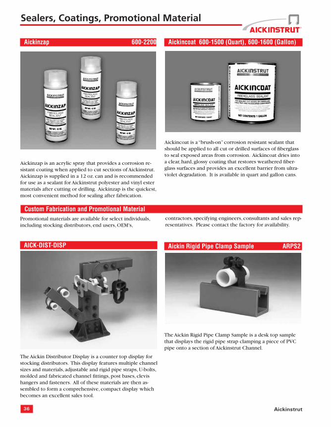
Aickinzap 600-2200
Aickinzap is an acrylic spray that provides a corrosion re-sistant coating when applied to cut sections of Aickinstrut. Aickinzap is supplied in a 12 oz. can and is recommended for use as a sealant for Aickinstrut polyester and vinyl ester materials after cutting or drilling. Aickinzap is the quickest, most convenient method for sealing after fabrication.
Aickincoat 600-1500 (Quart), 600-1600 (Gallon)
Aickincoat is a “brush-on” corrosion resistant sealant that should be applied to all cut or drilled surfaces of fi berglass to seal exposed areas from corrosion. Aickincoat dries into a clear, hard, glossy coating that restores weathered fi ber-glass surfaces and provides an excellent barrier from ultra-violet degradation. It is available in quart and gallon cans.
The Aickin Rigid Pipe Clamp Sample is a desk top sample that displays the rigid pipe strap clamping a piece of PVC pipe onto a section of Aickinstrut Channel.
Custom Fabrication and Promotional MaterialPromotional materials are available for select individuals, including stocking distributors, end users, OEM's,
The Aickin Distributor Display is a counter top display for stocking distributors. This display features multiple channel sizes and materials, adjustable and rigid pipe straps, U-bolts, molded and fabricated channel fi ttings, post bases, clevis hangers and fasteners. All of these materials are then as-sembled to form a comprehensive, compact display which becomes an excellent sales tool.
contractors, specifying engineers, consultants and sales rep-resentatives. Please contact the factory for availability.
37www.alliedeg.com
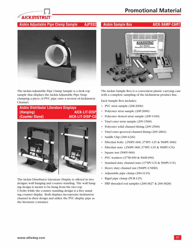
Aickin Adjustable Pipe Clamp Sample AJPSS2
The Aickin Adjustable Pipe Clamp Sample is a desk top sample that displays the Aickin Adjustable Pipe Strap clamping a piece of PVC pipe onto a section of Aickinstrut Channel.
Aickin Distributor Literature Displays(Hanging) AICK-LIT-DISP (Counter Stand) AICK-LIT-DISP-CS
The Aickin Distributor Literature Display is offered in two designs; wall hanging and counter standing. The wall hang-ing design is meant to be hung from the two top U-bolts while the counter standing design is a free stand-ing counter display. Both displays incorporate Aickinstrut channel in their design and utilize the PVC display pipe as the literature container.
Promotional Material
Aickin Sample Box AICK-SAMP-CART
The Aickin Sample Box is a convenient plastic carrying case with a complete sampling of the Aickinstrut product line.
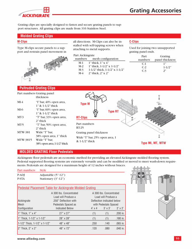
Aickingrate Fiberglass Grating was developed as a corro-sion resistant alternative to traditional metallic grating. Aickingrate will not rust, resists corrosion, lasts longer than metal and is maintenance free. Aickingrate never requires painting and can be installed with standard hand tools.
Aickingrate pultruded and molded gratings are ideal for the following applications:
Aickingrate pultruded and molded gratings are practical, economical solutions for applications where metallic grat-ings are not well suited. Aickingrate offers the best solu-tion for your industrial fl ooring needs.
Because Aickingrate is marketed with Aickinstrut Non-Me-tallic Strut Support Systems and Aickinshapes Non-Metallic Structural Shapes, the customer has the benefi t of purchas-ing all of these items from a single source, thereby minimiz-ing start-up and delivery delays.
Aickingrate stands ready to provide customer assistance through its network of distributors and mechanical sales representatives.
••••••••••••
Other valuable Aickingrate features include:
Availability of polyester or vinyl ester fi re retardant resin systems, which offer superior corrosion resistance, strength and fi re protection.
Applied grit anti-slip surface on molded grating, which provides superior traction.
Panels are strong and fl exible providing a comfortable working surface that enhances safety while reducing worker fatigue.
Panels are lightweight, easy to install and easy to remove for maintenance.
UV inhibitors are added to the base resin systems provid-ing optimum protection from the effects of weathering. Pultruded grating is further enhanced with the addition of a synthetic surfacing veil.
•
•
•
•
•
39www.alliedeg.com
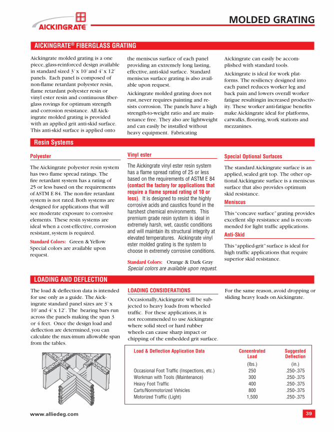
Aickingrate molded grating is a one piece, glass-reinforced design available in standard sized 3’ x 10’ and 4’ x 12’ panels. Each panel is composed of non-fl ame retardant polyester resin, fl ame retardant polyester resin or vinyl ester resin and continuous fi ber-glass rovings for optimum strength and corrosion resistance. All Aick-ingrate molded grating is provided with an applied grit anti-skid surface. This anti-skid surface is applied onto
the meniscus surface of each panel providing an extremely long lasting, effective, anti-skid surface. Standard meniscus surface grating is also avail-able upon request.
Aickingrate molded grating does notrust, never requires painting and re-sists corrosion. The panels have a high strength-to-weight ratio and are main-tenance free. They also are lightweight and can easily be installed without heavy equipment. Fabricating
Aickingrate can easily be accom-plished with standard tools.
Aickingrate is ideal for work plat-forms. The resiliency designed into each panel reduces worker leg and back pain and lowers overall worker fatigue resultingin increased productiv-ity. These worker anti-fatigue benefi ts make Aickingrate ideal for platforms, catwalks, fl ooring, work stations and mezzanines.
Polyester
The Aickingrate polyester resin system has two fl ame spread ratings. The fi re retardant system has a rating of 25 or less based on the requirements of ASTM E 84. The non-fi re retardant system is not rated. Both systems are designed for applications that will see moderate exposure to corrosive elements. These resin systems are ideal when a cost-effective, corrosion resistant, system is required.
Standard Colors: Green & YellowSpecial colors are available upon request.
Vinyl ester
The Aickingrate vinyl ester resin system has a flame spread rating of 25 or less based on the requirements of ASTM E 84 (contact the factory for applications that require a flame spread rating of 10 or less). It is designed to resist the highly corrosive acids and caustics found in the harshest chemical environments. This premium grade resin system is ideal in extremely harsh, wet, caustic conditions and will maintain its structural integrity at elevated temperatures. Aickingrate vinyl ester molded grating is the system to choose in extremely corrosive conditions.
Standard Colors: Orange & Dark GraySpecial colors are available upon request.
Special Optional Surfaces
The standard Aickingrate surface is an applied, sealed grit top. The other op-tional Aickingrate surface is a meniscus surface that also provides optimum skid resistance.
Meniscus
This “concave surface” grating provides excellent slip resistance and is recom-mended for light traffi c applications.
Anti-Skid
This “applied-grit” surface is ideal for high traffi c applications that require superior skid resistance.
AICKINGRATE® FIBERGLASS GRATING
Resin Systems
LOADING AND DEFLECTION
The load & defl ection data is intended for use only as a guide. The Aick-ingrate standard panel sizes are 3’ x 10’ and 4’ x 12’. The bearing bars run across the panels making the span 3 or 4 feet. Once the design load and defl ection are determined, you can calculate the max-imum allowable span from the tables.
LOADING CONSIDERATIONS
Occasionally, Aickingrate will be sub-jected to heavy loads from wheeled traffi c. For these applications, it is not recommended to use Aickingrate where solid steel or hard rubber wheels can cause sharp impact or chipping of the embedded grit surface.
For the same reason, avoid dropping or sliding heavy loads on Aickingrate.
Load & Deflection Application Data Concentrated Suggested Load Deflection
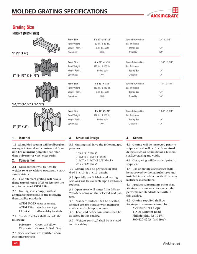
Panel Size: 3’ x 10’ & 44” x 8’ Space Between Bars 3/4” x 3-5/8”
Panel Weight: 83 lbs. & 83 lbs. Bar Thickness:
Weight Per Ft.: 2.75 lbs. sq/ft Bearing Bar 1/4”
Open Area: 69% Cross Bar 3/8”
Panel Size: 4’ x 12’, 4’ x 10’ Space Between Bars 1-1/4” x 1-1/4”
Panel Weight: 120 lbs. & 100 lbs. Bar Thickness:
Weight Per Ft.: 2.5 lbs. sq/ft Bearing Bar 1/4”
Open Area: 70% Cross Bar 1/4”
Panel Size: 4’ x 12’, 4’ x 10’ Space Between Bars 1-1/4” x 1-1/4”
Panel Weight: 180 lbs. & 150 lbs. Bar Thickness:
Weight Per Ft.: 3.75 lbs. sq/ft Bearing Bar 1/4”
Open Area: 70% Cross Bar 1/4”
Panel Size: 4’ x 12’, 4’ x 10’ Space Between Bars 1-3/4” x 1-3/4”
Panel Weight: 192 lbs. & 160 lbs. Bar Thickness:
Weight Per Ft.: 4.0 lbs. sq/ft Bearing Bar 1/4”
Open Area: 70% Cross Bar 1/4”
1” (1” X 4”)
1” (1-1/2” X 1-1/2”)
1-1/2” (1-1/2” X 1-1/2”)
2” (2” X 2”)
HEIGHT (MESH SIZE)
1. Material
1.1 All molded grating will be fi berglass roving reinforced and constructed from non-fi re retardant polyester, fi re retar-dant polyester or vinyl ester resin.
2. Composition
2.1 Glass content will be 35% by weight so as to achieve maximum corro-sion resistance.
2.2 Fire-retardant grating will have a fl ame spread rating of 25 or less per the requirements of ASTM E 84.
2.3 Grating shall comply with all applicable provisions of the following fl ammability standards:
ASTM D-635 (Rate of Burning)
ASTM E 84 (Surface Burning)
UL 94 V0 (Flammability Standard)
2.4 Standard colors shall include the following:
Polyester: Green & Yellow Vinyl ester: Orange & Dark Gray
2.5 Special colors are available upon customer request.
3. Structural Design
3.1 Grating shall have the following grid patterns:
1” x 4” (1” thick) 1 1/2” x 1 1/2” (1” thick) 1 1/2” x 1 1/2” (1 1/2” thick) 2” x 2” (2” thick)
3.2 Grating shall be provided in stan-dard 3’ x 10’ & 4’ x 12’ panels.
3.3 Specially cut & fabricated grating sections will be available upon customer request.
3.4 Open areas will range from 69% to 70% depending on the selected grid pat-tern.
3.5 Standard surface shall be a sealed, applied grit top surface with meniscus surface available upon request.3.6 Load and defl ection values shall be as stated in this catalog.
3.7 Weights per sq/ft shall be as stated in this catalog.
4. General
4.1 Grating will be inspected prior to shipment and will be free from visual defects such as delaminations, blisters, surface crazing and voids.
4.2 Cut grating will be sealed prior to shipment.
4.3 Use of grating accessories shallbe approved by the manufacturer and installed in accordance with the manu-facturers’ instructions.
4.4 Product substitutions other than Aickingrate must meet or exceed the performance standards set forth inthis catalog.
4.5 Grating supplied shall be Aickingrate as manufactured by: Aickinstrut/T.J. Cope 11500 Norcom Road Philadelphia, PA 19154 800-426-4293 (toll free)
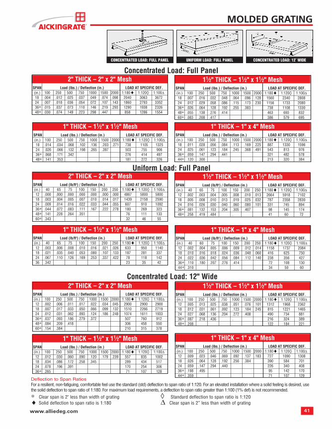
CONCENTRATED LOAD: 12" WIDEUNIFORM LOAD: FULL PANELCONCENTRATED LOAD: FULL PANEL
Deflection to Span RatiosFor a resilient, non-fatiguing, comfortable feel use the standard (std) deflection to span ratio of 1:120. For an elevated installation where a solid feeling is desired, use the solid deflection to span ratio of 1:180. For maximum load requirements, a deflection to span ratio greater than 1:100 (1% def) is not recommended.
∗ Clear span is 2" less than width of grating ◊ Standard deflection to span ratio is 1:120♦ Solid deflection to span ratio is 1:180 ∆ Clear span is 2” less than width of grating
Uniform Load: Full Panel11⁄2" THICK – 11⁄2" x 11⁄2" Mesh
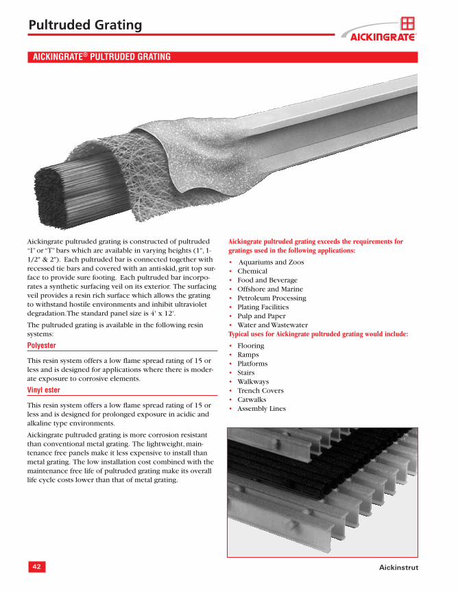
Aickingrate pultruded grating is constructed of pultruded “I” or “T” bars which are available in varying heights (1", 1-1/2" & 2"). Each pultruded bar is connected together with recessed tie bars and covered with an anti-skid, grit top sur-face to provide sure footing. Each pultruded bar incorpo-rates a synthetic surfacing veil on its exterior. The surfacing veil provides a resin rich surface which allows the grating to withstand hostile environments and inhibit ultraviolet degradation. The standard panel size is 4' x 12'.
The pultruded grating is available in the following resin systems:
Polyester
This resin system offers a low fl ame spread rating of 15 or less and is designed for applications where there is moder-ate exposure to corrosive elements.
Vinyl ester
This resin system offers a low fl ame spread rating of 15 or less and is designed for prolonged exposure in acidic and alkaline type environments.
Aickingrate pultruded grating is more corrosion resistant than conventional metal grating. The lightweight, main-tenance free panels make it less expensive to install than metal grating. The low installation cost combined with the maintenance free life of pultruded grating make its overall life cycle costs lower than that of metal grating.
Aickingrate pultruded grating exceeds the requirements for gratings used in the following applications:
Aquariums and ZoosChemicalFood and BeverageOffshore and MarinePetroleum ProcessingPlating FacilitiesPulp and PaperWater and Wastewater
Typical uses for Aickingrate pultruded grating would include:
All pultruded grating shall be constructed of glass rein-forced, fi re retardant polyester resin. Vinyl ester resin is available as a special order.
2. COMPOSITION
All pultruded glass reinforced grating shall have a syn-thetic veil applied on all exterior surfaces to improve weatherability and inhibit ultraviolet degradation. An ultraviolet stabilizer shall be incorporated in the resin formulation to further inhibit ultraviolet degradation.
Grating will have a fl ame spread rating of 15 per the requirements ASTM E 84.
Grating shall comply with all applicable provisions of the following fl ammability standards:
ASTM D-635 (Rate of Burning)ASTM E 84 (Surface Burning)UL 94 V0 (Flammability Standard)
2.4 Standard colors shall include the following:
Polyester (I-bar & T-bar):Yellow
Polyester (Wide T-bar):Dark Gray
2.5 Special colors are available upon customer request.
3. STRUCTURAL DESIGN
3.1 Grating shall have the following bar types and heights:I-bar (1”, 1-1/2” & 2” heights)T-bar (2” height)Wide T-bar (1” & 1-1/2” heights)
3.2 Grating shall be provided in standard 4’ x 12’ pan-els.
3.3 Specially cut & fabricated grating sections are available upon customer request.
3.4 Standard available “open areas” will be the following:I-bar (40% & 60%)T-bar (33% & 50%)Wide T-bar (25% & 38%)
3.5 Special “open areas” are available upon customer request.
3.6 Grating shall be manufactured from thermally cured pultruded structural load and tie bar com-ponents.
3.7 Grating shall be provided with a recessed tie bar design and grit top surface for maximum skid resistance.
3.8 Grating shall be an assembled and bonded notched tie bar system to provide both a mechanical and bonded panel connection.
3.9 Load, defl ection and panel weight values shall be as stated in this catalog.
4. GENERAL
4.1 Grating will be inspected prior to shipment and will be free from visual defects.
4.2 All cut ends will be sealed prior to shipment.
4.3 Grating shall be fully supported according to the manufacturer guidelines.
4.4 Use of grating accessories shall be approved by the manufacturer and installed in accordance with the manufacturers’ instructions.
4.5 Product substitutions other than Aickingrate must meet or exceed the performance standards set forth in this catalog.
4.6 Grating supplied shall be Aickingrate as manufac-tured by:Aickinstrut/T.J. Cope11500 Norcom RoadPhiladelphia, PA 19154800-426-4293 (toll free)215-961-2570 (phone)215-961-2580 (fax)
Aickingrate Pultruded Specifi cations
Pultruded Grating Specifi cations
44 Aickinstrut
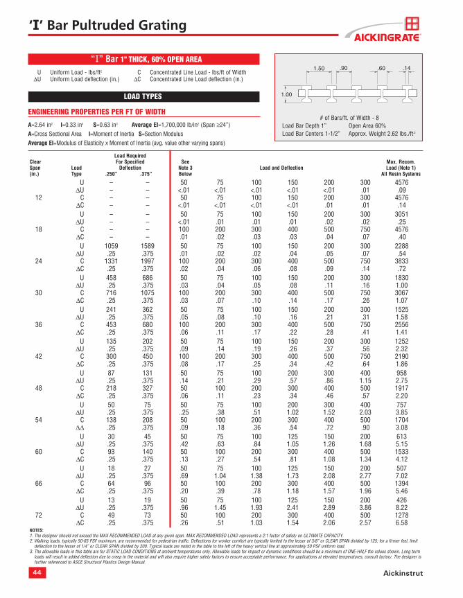
# of Bars/ft. of Width - 8 Load Bar Depth 1” Open Area 60% Load Bar Centers 1-1/2” Approx. Weight 2.62 lbs./ft.2
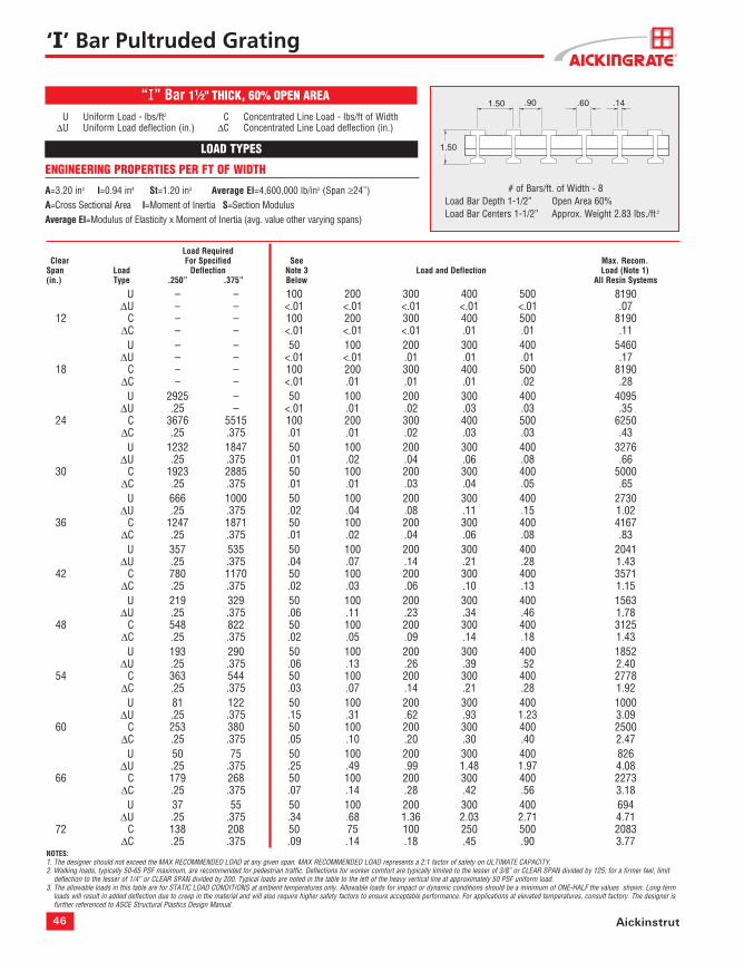
ENGINEERING PROPERTIES PER FT OF WIDTH
A=2.64 in2 I=0.33 in4 S=0.63 in3 Average EI=1,700,000 lb/in2 (Span ≥24”)A=Cross Sectional Area I=Moment of Inertia S=Section ModulusAverage EI=Modulus of Elasticity x Moment of Inertia (avg. value other varying spans)
“I” Bar 1" THICK, 60% OPEN AREA
Load RequiredClear For Specified See Max. Recom.Span Load Deflection Note 3 Load and Deflection Load (Note 1)(in.) Type .250” .375” Below All Resin Systems
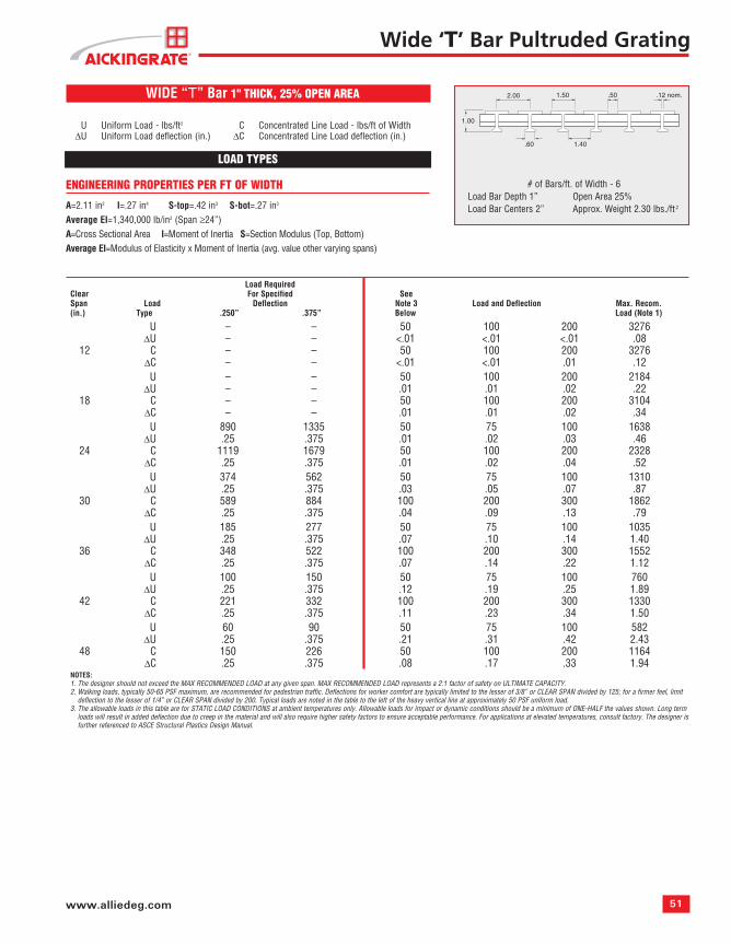
NOTES:1. The designer should not exceed the MAX RECOMMENDED LOAD at any given span. MAX RECOMMENDED LOAD represents a 2:1 factor of safety on ULTIMATE CAPACITY.2. Walking loads, typically 50-65 PSF maximum, are recommended for pedestrian traffic. Deflections for worker comfort are typically limited to the lesser of 3/8” or CLEAR SPAN divided by 125; for a firmer feel, limit
deflection to the lesser of 1/4” or CLEAR SPAN divided by 200. Typical loads are noted in the table to the left of the heavy vertical line at approximately 50 PSF uniform load.3. The allowable loads in this table are for STATIC LOAD CONDITIONS at ambient temperatures only. Allowable loads for impact or dynamic conditions should be a minimum of ONE-HALF the values shown. Long term
loads will result in added deflection due to creep in the material and will also require higher safety factors to ensure acceptable performance. For applications at elevated temperatures, consult factory. The designer is further referenced to ASCE Structural Plastics Design Manual.
LOAD TYPES
U Uniform Load - lbs/ft2 C Concentrated Line Load - lbs/ft of Width∆U Uniform Load deflection (in.) ∆C Concentrated Line Load deflection (in.)
‘I’ Bar Pultruded Grating
1.50 .14
1.00
.90 .60
45www.alliedeg.com
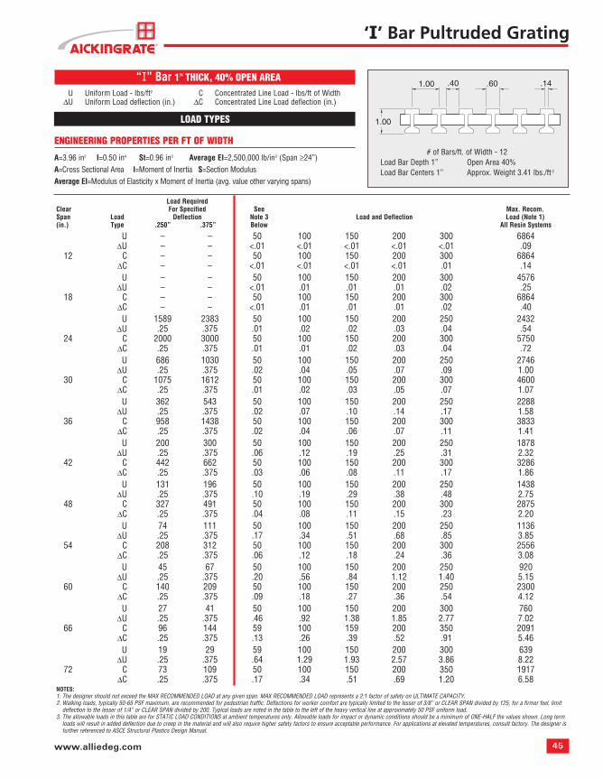
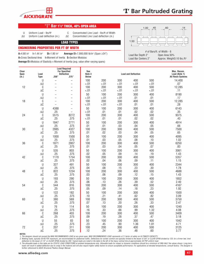
Load RequiredClear For Specified See Max. Recom.Span Load Deflection Note 3 Load and Deflection Load (Note 1)(in.) Type .250” .375” Below All Resin Systems
NOTES:1. The designer should not exceed the MAX RECOMMENDED LOAD at any given span. MAX RECOMMENDED LOAD represents a 2:1 factor of safety on ULTIMATE CAPACITY.2. Walking loads, typically 50-65 PSF maximum, are recommended for pedestrian traffic. Deflections for worker comfort are typically limited to the lesser of 3/8” or CLEAR SPAN divided by 125; for a firmer feel, limit
deflection to the lesser of 1/4” or CLEAR SPAN divided by 200. Typical loads are noted in the table to the left of the heavy vertical line at approximately 50 PSF uniform load.3. The allowable loads in this table are for STATIC LOAD CONDITIONS at ambient temperatures only. Allowable loads for impact or dynamic conditions should be a minimum of ONE-HALF the values shown. Long term
loads will result in added deflection due to creep in the material and will also require higher safety factors to ensure acceptable performance. For applications at elevated temperatures, consult factory. The designer is further referenced to ASCE Structural Plastics Design Manual.
# of Bars/ft. of Width - 12 Load Bar Depth 1” Open Area 40% Load Bar Centers 1” Approx. Weight 3.41 lbs./ft.2
ENGINEERING PROPERTIES PER FT OF WIDTH
A=3.96 in2 I=0.50 in4 St=0.96 in3 Average EI=2,500,000 lb/in2 (Span ≥24”)A=Cross Sectional Area I=Moment of Inertia S=Section Modulus Average EI=Modulus of Elasticity x Moment of Inertia (avg. value other varying spans)
U Uniform Load - lbs/ft2 C Concentrated Line Load - lbs/ft of Width∆U Uniform Load deflection (in.) ∆C Concentrated Line Load deflection (in.)
LOAD TYPES
“I” Bar 1" THICK, 40% OPEN AREA
‘I’ Bar Pultruded Grating
1.00 .14
1.00
.40 .60
46 Aickinstrut
Load Required Clear For Specified See Max. Recom.Span Load Deflection Note 3 Load and Deflection Load (Note 1)(in.) Type .250” .375” Below All Resin Systems
NOTES:1. The designer should not exceed the MAX RECOMMENDED LOAD at any given span. MAX RECOMMENDED LOAD represents a 2:1 factor of safety on ULTIMATE CAPACITY.2. Walking loads, typically 50-65 PSF maximum, are recommended for pedestrian traffic. Deflections for worker comfort are typically limited to the lesser of 3/8” or CLEAR SPAN divided by 125; for a firmer feel, limit
deflection to the lesser of 1/4” or CLEAR SPAN divided by 200. Typical loads are noted in the table to the left of the heavy vertical line at approximately 50 PSF uniform load.3. The allowable loads in this table are for STATIC LOAD CONDITIONS at ambient temperatures only. Allowable loads for impact or dynamic conditions should be a minimum of ONE-HALF the values shown. Long term
loads will result in added deflection due to creep in the material and will also require higher safety factors to ensure acceptable performance. For applications at elevated temperatures, consult factory. The designer is further referenced to ASCE Structural Plastics Design Manual.
ENGINEERING PROPERTIES PER FT OF WIDTH
A=3.20 in2 I=0.94 in4 St=1.20 in3 Average EI=4,600,000 lb/in2 (Span ≥24”)A=Cross Sectional Area I=Moment of Inertia S=Section Modulus Average EI=Modulus of Elasticity x Moment of Inertia (avg. value other varying spans)
U Uniform Load - lbs/ft2 C Concentrated Line Load - lbs/ft of Width∆U Uniform Load deflection (in.) ∆C Concentrated Line Load deflection (in.)
LOAD TYPES
# of Bars/ft. of Width - 8 Load Bar Depth 1-1/2” Open Area 60% Load Bar Centers 1-1/2” Approx. Weight 2.83 lbs./ft.2
“I” Bar 11⁄2" THICK, 60% OPEN AREA
‘I’ Bar Pultruded Grating
1.50 .14
1.50
.90 .60
47www.alliedeg.com
Load RequiredClear For Specified See Max. Recom.Span Load Deflection Note 3 Load and Deflection Load (Note 1)(in.) Type .250” .375” Below All Resin Systems
NOTES:1. The designer should not exceed the MAX RECOMMENDED LOAD at any given span. MAX RECOMMENDED LOAD represents a 2:1 factor of safety on ULTIMATE CAPACITY.2. Walking loads, typically 50-65 PSF maximum, are recommended for pedestrian traffic. Deflections for worker comfort are typically limited to the lesser of 3/8” or CLEAR SPAN divided by 125; for a firmer feel, limit
deflection to the lesser of 1/4” or CLEAR SPAN divided by 200. Typical loads are noted in the table to the left of the heavy vertical line at approximately 50 PSF uniform load.3. The allowable loads in this table are for STATIC LOAD CONDITIONS at ambient temperatures only. Allowable loads for impact or dynamic conditions should be a minimum of ONE-HALF the values shown. Long term
loads will result in added deflection due to creep in the material and will also require higher safety factors to ensure acceptable performance. For applications at elevated temperatures, consult factory. The designer is further referenced to ASCE Structural Plastics Design Manual.
ENGINEERING PROPERTIES PER FT OF WIDTH
A=4.80 in2 I=1.44 in4 St=1.80 in3 Average EI=7,000,000 lb/in2 (Span ≥24”)A=Cross Sectional Area I=Moment of Inertia S=Section Modulus Average EI=Modulus of Elasticity x Moment of Inertia (avg. value other varying spans)
U Uniform Load - lbs/ft2 C Concentrated Line Load - lbs/ft of Width∆U Uniform Load deflection (in.) ∆C Concentrated Line Load deflection (in.)
LOAD TYPES
# of Bars/ft. of Width - 6 Load Bar Depth 2” Open Area 50% Load Bar Centers 2” Approx. Weight3.10 lbs./ft.2
“I” Bar 11⁄2" THICK, 40% OPEN AREA
‘I’ Bar Pultruded Grating
1.00 .14
1.50
.40 .60
48 Aickinstrut
Load RequiredClear For Specified See Max. Recom.Span Load Deflection Note 3 Load and Deflection Load (Note 1)(in.) Type .250” .375” Below All Resin Systems
NOTES:1. The designer should not exceed the MAX RECOMMENDED LOAD at any given span. MAX RECOMMENDED LOAD represents a 2:1 factor of safety on ULTIMATE CAPACITY.2. Walking loads, typically 50-65 PSF maximum, are recommended for pedestrian traffic. Deflections for worker comfort are typically limited to the lesser of 3/8” or CLEAR SPAN divided by 125; for a firmer feel, limit
deflection to the lesser of 1/4” or CLEAR SPAN divided by 200. Typical loads are noted in the table to the left of the heavy vertical line at approximately 50 PS Uniform load.3. The allowable loads in this table are for STATIC LOAD CONDITIONS at ambient temperatures only. Allowable loads for impact or dynamic conditions should be a minimum of ONE-HALF the values shown. Long term
loads will result in added deflection due to creep in the material and will also require higher safety factors to ensure acceptable performance. For applications at elevated temperatures, consult factory. The designer is further referenced to ASCE Structural Plastics Design Manual.
# of Bars/ft. of Width - 6 Load Bar Depth 2” Open Area 50% Load Bar Centers 2” Approx. Weight3.10 lbs./ft.2
ENGINEERING PROPERTIES PER FT OF WIDTH
A=3.20 in2 I=1.68 in4 St=1.96 in3 Sb=1.47 in3
Average EI=7,600,000 lb/in2 (Span ≥24”)A=Cross Sectional Area I=Moment of Inertia S=Section Modulus (Top, Bottom)Average EI=Modulus of Elasticity x Moment of Inertia (avg. value other varying spans)
U Uniform Load - lbs/ft2 C Concentrated Line Load - lbs/ft of Width∆U Uniform Load deflection (in.) ∆C Concentrated Line Load deflection (in.)
LOAD TYPES
“T” Bar 2" THICK, 50% OPEN AREA
‘T’ Bar Pultruded Grating
2.00 .14
2.00
1.001.00
.60 1.40
49www.alliedeg.com
U Uniform Load - lbs/ft2 C Concentrated Line Load - lbs/ft of Width∆U Uniform Load deflection (in.) ∆C Concentrated Line Load deflection (in.)
LOAD TYPES
Load RequiredClear For Specified See Max. Recom.Span Load Deflection Note 3 Load and Deflection Load (Note 1)(in.) Type .250” .375” Below All Resin Systems
NOTES:1. The designer should not exceed the MAX RECOMMENDED LOAD at any given span. MAX RECOMMENDED LOAD represents a 2:1 factor of safety on ULTIMATE CAPACITY.2. Walking loads, typically 50-65 PSF maximum, are recommended for pedestrian traffic. Deflections for worker comfort are typically limited to the lesser of 3/8” or CLEAR SPAN divided by 125; for a firmer feel, limit
deflection to the lesser of 1/4” or CLEAR SPAN divided by 200. Typical loads are noted in the table to the left of the heavy vertical line at approximately 50 PSF uniform load.3. The allowable loads in this table are for STATIC LOAD CONDITIONS at ambient temperatures only. Allowable loads for impact or dynamic conditions should be a minimum of ONE-HALF the values shown. Long term
loads will result in added deflection due to creep in the material and will also require higher safety factors to ensure acceptable performance. For applications at elevated temperatures, consult factory. The designer is further referenced to ASCE Structural Plastics Design Manual.
# of Bars/ft. of Width - 12 Load Bar Depth 2” Open Area 33% Load Bar Centers 1-1/2” Approx. Weight 4.00 lbs./ft.2
ENGINEERING PROPERTIES PER FT OF WIDTHA=4.28 in2 I=2.24 in4 St=2.61 in3 Sb=1.96 in3
Average EI=9,200,000 lb/in2 (Span ≥24”)A=Cross Sectional Area I=Moment of Inertia S=Section Modulus (Top, Bottom)Average EI=Modulus of Elasticity x Moment of Inertia (avg. value other varying spans)
“T” Bar 2" THICK, 33% OPEN AREA
‘T’ Bar Pultruded Grating
1.50 .14
2.00
1.00
.60
.50
1.00
50 Aickinstrut
Aickingrate Wide T-Bar pultruded grat-ing provides a lightweight, non-skid, durable alternative to metallic grating used for pedestrian walkway traffi c.
The Aickingrate Wide T-Bar grit-top grating offers excellent protection for pedestrian traffi c particularly in wet environments.
This low-cost grating is an excel-lent alternative to metal grating for wet areas with high volumes of foot traffi c.
# of Bars/ft. of Width - 5 Load Bar Depth 1 Open Area 38% Load Bar Centers 2.4” Approx. Weight 1.90 lbs./ft.2
U Uniform Load - lbs/ft2 C Concentrated Line Load - lbs/ft of Width∆U Uniform Load deflection (in.) ∆C Concentrated Line Load deflection (in.)
LOAD TYPESENGINEERING PROPERTIES PER FT OF WIDTH
A=1.76 in2 I=.23 in4 S-top=.35 in3 S-bot=.22 in3
Average EI=1,200,000 lb/in2 (Span ≥24”)A=Cross Sectional Area I=Moment of Inertia S=Section Modulus (Top, Bottom)Average EI=Modulus of Elasticity x Moment of Inertia (avg. value other varying spans)
Load RequiredClear For Specified See Span Load Deflection Note 3 Load and Deflection Max. Recom.(in.) Type .250” .375” Below Load (Note 1)
∆C .25 .375 .10 .20 .40 .60 .80 1.94NOTES:1. The designer should not exceed the MAX RECOMMENDED LOAD at any given span. MAX RECOMMENDED LOAD represents a 2:1 factor of safety on ULTIMATE CAPACITY.2. Walking loads, typically 50-65 PSF maximum, are recommended for pedestrian traffic. Deflections for worker comfort are typically limited to the lesser of 3/8” or CLEAR SPAN divided by 125; for a firmer feel, limit
deflection to the lesser of 1/4” or CLEAR SPAN divided by 200. Typical loads are noted in the table to the left of the heavy vertical line at approximately 50 PSF uniform load.3. The allowable loads in this table are for STATIC LOAD CONDITIONS at ambient temperatures only. Allowable loads for impact or dynamic conditions should be a minimum of ONE-HALF the values shown. Long term
loads will result in added deflection due to creep in the material and will also require higher safety factors to ensure acceptable performance. For applications at elevated temperatures, consult factory. The designeris further referenced to ASCE Structural Plastics Design Manual.
Wide ‘T’ Bar Pultruded Grating
WIDE “T” Bar 1" THICK, 38% OPEN AREA 2.40 .12 nom.
1.00
1.50 .90
.60 1.80
51www.alliedeg.com
Load RequiredClear For Specified See Span Load Deflection Note 3 Load and Deflection Max. Recom.(in.) Type .250” .375” Below Load (Note 1)
NOTES:1. The designer should not exceed the MAX RECOMMENDED LOAD at any given span. MAX RECOMMENDED LOAD represents a 2:1 factor of safety on ULTIMATE CAPACITY.2. Walking loads, typically 50-65 PSF maximum, are recommended for pedestrian traffic. Deflections for worker comfort are typically limited to the lesser of 3/8” or CLEAR SPAN divided by 125; for a firmer feel, limit
deflection to the lesser of 1/4” or CLEAR SPAN divided by 200. Typical loads are noted in the table to the left of the heavy vertical line at approximately 50 PSF uniform load.3. The allowable loads in this table are for STATIC LOAD CONDITIONS at ambient temperatures only. Allowable loads for impact or dynamic conditions should be a minimum of ONE-HALF the values shown. Long term
loads will result in added deflection due to creep in the material and will also require higher safety factors to ensure acceptable performance. For applications at elevated temperatures, consult factory. The designer is further referenced to ASCE Structural Plastics Design Manual.
U Uniform Load - lbs/ft2 C Concentrated Line Load - lbs/ft of Width∆U Uniform Load deflection (in.) ∆C Concentrated Line Load deflection (in.)
# of Bars/ft. of Width - 6 Load Bar Depth 1” Open Area 25% Load Bar Centers 2” Approx. Weight 2.30 lbs./ft.2
ENGINEERING PROPERTIES PER FT OF WIDTH
A=2.11 in2 I=.27 in4 S-top=.42 in3 S-bot=.27 in3
Average EI=1,340,000 lb/in2 (Span ≥24”)A=Cross Sectional Area I=Moment of Inertia S=Section Modulus (Top, Bottom)Average EI=Modulus of Elasticity x Moment of Inertia (avg. value other varying spans)
Wide ‘T’ Bar Pultruded Grating
WIDE “T” Bar 1" THICK, 25% OPEN AREA
LOAD TYPES
2.00 .12 nom.
1.00
1.50 .50
.60 1.40
52 Aickinstrut
To order Aickingrate, use the following part number scheme to create the correct part number.* To order non-fi re retardant polyester, add suffi x “NFR” to end of part number.
Molded stair treads are available in the same resin formulations as the standard molded grating panels. Each panel in-corporates an applied, grit surface with an extra-thick, dark colored nosing. This leading edge color contrast increases the stair tread visibility and prevents slips and falls on stairways.
All stair treads are 1-1/2” thick and pro-vided in a 1-1/2” square mesh confi gura-tion. The standard stair tread panel size is 22-1/2” x 120”. Each panel weighs approximately 105 pounds.
Standard Colors: Green, Yellow, Gray and Orange
Special colors are available upon request.
Aickingrate stair tread panels can be cut with the same tools that are used on the Aickingrate molded grating panels.
Aikengrate Stair Trends are available in either molded or pultruded designs. Both designs incorporate an anti-skid, grit top surface.
Pultruded stair treads incorporate the same performance characteristics as the Aickingrate pultruded grating panels. All stair treads are slip-resis-tant, non-conductive and offer a high level of safety, strength and corrosion resistance.
Pultruded stair treads are available in either polyester or vinyl ester resin types. The standard stair tread panel size is 1’ x 10’. Stair treads are avail-able in 1”, 1-1/2” & 2” depths. The available bar shapes are “I” bar and “T”
bar. All pultruded stair treads incorpo-rate a color contrast nosing to allow for quick and easy visual distinction, which prevents slips and falls.
Standard Colors: Yellow (Polyester), Gray (Vinyl ester)
AICKINGRATE STAIR TREADS
54 Aickinstrut
Aickincoat sealer is recommended after cutting Aickingrate. Aickincoat seals the exposed grating ends and maintains the corrosion resistance and integrity of the grating panel.
Part number Size
600-1500 Quart
600-1600 Gallon
600-2200 Spray
Aickinplate Panel Weight 45 lbs. 12 (in.) Use on flat
3/16" Weight/Sq. Ft. 1.4 lbs. 18 solid surface only
Aickinplate is a molded, non-skid fi ber-glass plate that offers an economical, safe solution for slippery walking surfaces. The non-skid surface pro-vides excellent traction even when oil or other slippery liquids are present. Because Aickinplate is molded from
fi berglass, it provides superior cor-rosion resistance and never requires painting. Aikinplate is a structural fl oor plate that is non-porous and cleans easily with water.
Aickinplate is easy to fabricate. It can be cut with masonry blades and drilled with standard carbide-tipped drill bits. The standard panel size is 4' x 8' and they are available in three thickness'; 3/16", 1/2" and 3/8". All panels will be constructed from both non-fi re retar-dant or fi re retardant polyester resin and fi re retardant vinyl ester resins. A USDA approved, polyester resin Aickin-plate is available.
Note: Install clips a maximum of every 48” and use at least 8 clips per 4’x12’ panel.
Capacity
Aickincoat Sealer
AICKINPLATE
Grating Accessories
55www.alliedeg.com
Grating clips are specially designed to fasten and secure grating panels to sup-port structures. All grating clips are made from 316 Stainless Steel.
M-Clips
Type M-clips secure panels to a sup-port and restrain panel movement in
all directions. M-Clips can also be in-stalled with self-tapping screws when attaching to metal supports.
Molded Grating Clips
Pedestal Placement Table for Aickingrate Molded Grating A 300 lbs. Concentrated A 300 lbs. Concentrated Load will Produce a Load will Produce aAickingrate .250” Deflection with Deflection indicated belowMesh Pedestals Spaced as with Pedestals SpacedConfiguration Indicated Below 4’ x 4 3’ x 3’ 2’ x 2’
1” Thick, 1” x 4” 27” x 27” (1) (1) .200 in.
1” Thick, 1-1/2” x 1-1/2” 28” x 28” (1) (1) .180 in.
1-1/2” Thick, 1-1/2” x 1-1/2” 48” x 48” .250 .140 .065 in.
2” Thick, 2” x 2” 48” x 72” .120 .080 .040 in.
Aickingrate fl oor pedestals are an economic method for providing an elevated Aickingrate molded fl ooring system. Pedestal supported fl ooring systems are extremely versatile and can be modifi ed or moved to meet wash-down require-ments. Pedestals are designed for a maximum height of 12 inches without braces.
MT-5 “T” bar, 50% open area, 2” thickMTW-381 Wide “T” bar,
38% open area, 1” thickMTW-3815 Wide “T” bar,
38% open area, 1-1/2” thick
RT-Clips
Part numbersRT-25
Grating panel thickness
Wide “T” bar, 25% open area, 1 & 1-1/2” thick
Grating Accessories
56 Aickinstrut
The information contained in this table is intended to only be used as a guide for molded & pultruded grating. Because actual condi-tions may differ, the end-user must determine if the grating will withstand the intended environment.
C=Continuous exposure of the grating to the Chemical Environment listed at the temperature listed.S=Frequent exposure of the grating to splashes and spills from the Chemical Environment listed with that environment at the temperature listed.I=Infrequent exposure of the grating to splashes and spills from the Chemical Environment listed with that environment at the temperature listed and the spill im-
mediately cleaned up or washed from the grating.N=Not recommended for the concentrations and temperatures listed.T=Test
Consult Aickingrate for corrosion recommendations at concentrations, temperatures or chemi-cals not listed in this guide.
Max. Temp. is 180°F for Vinylester 150°F for Polyester.
Chemical Environment % Concentration Temp. ˚F POLY VE
Acetic Acid 50 Max. C C
Acetone 100 75 I N
Alcohols 100 120 I I
Aluminum All Max. C C
Aluminum Chloride All Max. C C
Aluminum Fluoride 20 75 I I
Ammonium Hydroxide 30 75 I N
Ammonium Salts - Neutral All 120 C S
Ammonium Salts - Aggressive All 75 T N
Aromatic Solvents All 75 N N
Barium Salts All Max. C C
Benzene 100 140 I N
Black Liquor (Pulp Mill) All Max. I N
Bleach Liquor (Pulp Mill) All Max. I N
Calcium Hydroxide 25 Max. S I
Calcium Hypochlorite All Max. I N
Calcium Salts All Max. C C
Carbon Tetrachloride 100 75 S N
Chlorinated Hydrocarbons 100 75 T T
Chlorine Dioxide Sat. 140 S N
Chlorine Water Sat. 120 I N
Chlorine, Wet Sat. Max. N N
Chlorobenzene 100 75 N N
Chlorobenzene All Up to 100 N N
Chloroform 100 75 N N
Chromic Acid 50 140 I N
Citric Acid All Max. C C
Copper Cyanide Plating All 125 S I
Copper Salts All Max. C C
Crude Oil (Sweet or Sour) All Max. C C
Dichlorobenzene 100 75 N N
Ethers 75 N N
Ferric Chloride 100 Max. C C
Ferric Salts All Max. C C
Fluoride Salts + HCI All 75 I N
Fluosilicic Acid 10 75 S I
Formaldehyde 37 150 S I
Formic Acid 25 100 S I
Fuel (Diesel, Jet, Gasoline) All 100 C C
Glycerine 100 Max. C C
Green Liquor (Pulp Mill) All Max. I N
Hydrobromic Acid 48 Max. I N
Hydrochloric Acid 10 Max. S S
Hydrochloric Acid 30 Max. I I
Chemical Environment % Concentration Temp. ˚F POLY VE
Hydrochloric Acid (Concentrated) All Up to 180 N N
Hydrocyanic Acid All Max. S I
Hydrofluoric Acid 20 75 N N
Hydrogen Peroxide 30 75 S N
Lactic Acid 100 Max. C C
Lime Slurry Sat. Max. C C
Lithium Salts All Max. C C
Magnesium Salts All Max. C I
Maleic Acid 100 Max. S I
Mercury Chloride 100 Max. C C
Nickel Salts All Max. C C
Nitric Acid 20 120 I I
Nitric Acid 35 100 I N
Nitric Acid 40 Ambient N N
Nitric Hydrofluoric 20:2 75 N N
Nitrous Acid 10 75 C C
Ozone for Sewage Treatment 100 C C
Perchloroethylene 100 75 I N
Phenol 10 75 I N
Phenol 88 Ambient N N
Phosphoric Acid 85 Max. C S
Phosphoric Acid, Super 115 Max. S N
Potassium Hydroxide 10 120 S N
Potassium Salts All Max. C C
Silver Nitrate 100 Max. C C
Sodium Cyanide All 75 S I
Sodium Hydroxide 50 Max. I N
Sodium Hydroxide 10 Max. N N
Sodium Hypochlorite (Stable) 10 100 S I
Sodium Salts-Neutral All Max. C C
Sodium Salts-Aggressive All 75 T N
Sulfur Dioxide Sat. Max. S S
Sulfuric Acid 25 Max. S I
Sulfuric Acid 50 Max. S N
Sulfuric Acid 75 100 I N
Toluene 100 120 I N
Trichloroethane 1,1,1 All 75 I N
Trisodium Phosphate 50 Max. I N
Water (Fresh, Salt, Moderate, D.I.) 100 Max. C C
Wet Chlorine/Hydrochloric Acid) 10-20 Up to 350 N N
Other Non-Metallic products designed to work with Aickinstrut®
can be found in COPE-GLAS™
• TJ Cope Cable Tray • AFC Cable Systems® • Allied Tube & Conduit • Power-Strut® Metal & Fiberglass FramingAickinstrut, TJ Cope, AFC Cable Systems, Allied, Power-Strut and Tyco are trademarks or registered trademarks of Tyco and/or its affiliates in the United States and in other countries.
All other brand names, product names, or trademarks belong to their respective holders.
COPE-GLAS™ is a Fiberglass Cable Tray System of products, UL Listed, accepted industry wide and
exceeds industry standards for chemical resistance, strength, flame resistance and ultraviolet protection.
To get a catalog ask your Rep, or go to our website atwww.alliedeg.com