17
EXPANSION JOINT TO ENGINEER’S DETAILS CONCRETE Site Installation Manual Fiberglass Drain Systems ACO Construction & Building Products ACO DRAIN

EXPANSION JOINT TO
ENGINEER’S DETAILS
BEDDING LAYER
SOIL
CONCRETE
Site Installation Manual
Fiberglass Drain Systems
ACO Construction & Building Products
ACO DRAIN

2
(800) 543-4764 www.ACODrain.us
FIBER
GLA
SS
ACO Drain consists of a full range of modular channels with lockable gratings. Systems include catch basins, end caps, and other accessories.
When installed correctly, ACO Drain products are designed to withstand a variety of loadings as classified by EN 1433/DIN 19580 (The only standards specifically for trench drain systems).
Getting Started
ContentsFiberglass products should be handled with care as they can be damaged by impact from other products, or machinery.
Typical equipment necessary for installation may include:
• Excavating equipment
• String-line and laser level
• Measuring tools
• Drill, grinder and/or saw
• Concrete - 4,000 psi minimum compressive strength
• Gloves, respirator and eye protection
Getting Started 2
Health and Safety 3
Installation Sections 4
1. Excavation 5
2. Channel / Frame Assembly 6
3. On-site Fabrications 7
4. Channel Adapters 8
5. Pipe Connections - Vertical Outlet Adapters 9 - Pipe Adapters 10
6. Positioning of Channels - Hanging Method 11 - Rebar Support Method 12
7. Concrete Pour 13
8. Concrete Finishing 14
9. Fit Grates 15
10. Final Inspections 16
11. Maintenance 17

3
(800) 543-4764 www.ACODrain.us
FIBER
GLA
SS
Commercial Trench Drains
Health and SafetyFiberglass is produced from glass mattings bonded together using a resin binder.
Main hazards include: • Abrasive damage to hands.• Respirable dust from grinding, cutting or drilling.• Grinding, cutting, etc. may project fragments at speed causing possible impact damage.
Gloves, eye protection and a respirator should be worn to avoid these hazards.
Grates and frames made from metals are either castings or fabricated.
Main hazards include: • Abrasive damage/cuts to hands.• Respirable dust from grinding or cutting.• Grinding, cutting, etc. may generate sparks; flammable items should be removed from area. Gloves, eye protection, and respirator should be worn to avoid these hazards. Operations should be conducted away from areas of fire or explosion hazard.
Make sure arrow stickers on sides of channel all point in the intended direction of flow (outlet point).
male end (down stream)
female end (up stream)
Channel sequence number
Bracing information
Flow direction indicator arrow
Bracing block
Bolted grates
Trash bucket
Catch basin
4
(800) 543-4764 www.ACODrain.us
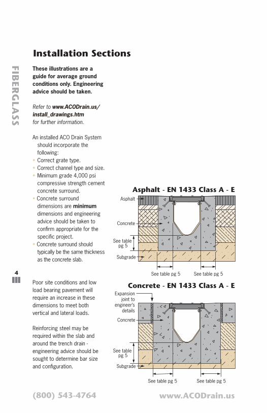
Asphalt - EN 1433 Class A - E
Concrete - EN 1433 Class A - E
See table pg 5
See table pg 5 See table pg 5
Subgrade
Asphalt
Concrete
See table pg 5
See table pg 5 See table pg 5
Subgrade
Concrete
Expansionjoint to
engineer’sdetails
FIBER
GLA
SS
Installation SectionsThese illustrations are a guide for average ground conditions only. Engineering advice should be taken.
Refer to
for further information.
An installed ACO Drain System should incorporate the following:
• Correct grate type.• Correct channel type and size.• Minimum grade 4,000 psi
compressive strength cement concrete surround.
• Concrete surround dimensions are minimum dimensions and engineering advice should be taken to confirm appropriate for the specific project.
• Concrete surround should typically be the same thickness as the concrete slab.
Poor site conditions and low load bearing pavement will require an increase in these dimensions to meet both vertical and lateral loads.
Reinforcing steel may be required within the slab and around the trench drain - engineering advice should be sought to determine bar size and configuration.
5
(800) 543-4764 www.ACODrain.us
FIBER
GLA
SS
Commercial Trench Drains
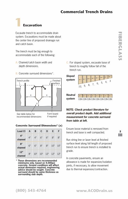
Form board if required
Trench profile
x x
Finishedsurface
See table below for recommended dimensions
x
C. For sloped system, excavate base of trench to roughly follow fall of the trench run.
Ensure loose material is removed from trench and base is well compacted.
Run string line or laser level at finished surface level along full length of proposed trench run to ensure trench is installed to grade.
In concrete pavements, ensure an allowance is made for expansion/isolation joints, if necessary, to allow movement due to thermal expansion/contraction.
1Excavation
Excavate trench to accommodate drain system. Excavations must be made about the center line of proposed drainage run and catch basin.
The trench must be big enough to accommodate each of the following:
A. Channel/catch basin width and depth dimensions.
B. Concrete surround dimensions*.
10,
010, 010, 010, 010, 010, 010, 010, 010
9, 8, 7, 6, 5, 4, 3
Sloped system
Neutral system 03N 03N 03N 03N 03N 03N 03N 03N
NOTE: Check product literature for overall product depth. Add additional measurement for concrete surround from table at left.
* These dimensions are recommended minimums only, based on 4,000psi concrete. Ground conditions will affect actual dimension required; engineering advice should be sought. Concrete surround should be same thickness as surrounding slab depth.
Load Cl A B C D E F
4”
channel4” 4” 6” 6” 8” 8”
8”
channel6” 6” 8” 8” 10” 10”
12”
channel8” 10” 10” 12” 12” 12”
Concrete Surround Dimensions* (x)

6
(800) 543-4764 www.ACODrain.us
FIBER
GLA
SS
2Channel Bracing
5. Refer to red sticker on side of channels for specified number of polystyrene blocks for each channel. Bracing deeper channels during concrete pour prevents bowing due to hydrostatic pressure from concrete.
NOTE: Ensure blocks remain vertically centered between channel walls.
Once channels are positioned, add blocks at joints to maintain correct horizontal alignment.
Frame
Channel
Serrated push pin
Inside of channel
Channel joint
Bracing block
Channel / Frame Assembly
1. Set frame upside down.
2. Push fiberglass body onto frame - body must sit outside frame.
3. The female end of channel should extend past the end of grate frame approx. 2 inches. The male end is flush with grate frame.
Female end
4. Align holes in frame and channel and fasten with push pins (supplied) inserted from inside of channel.

7
(800) 543-4764 www.ACODrain.us
FIBER
GLA
SS
Commercial Trench Drains
On-Site Fabrications
When cutting channels and/or grates, gloves, protective eye wear and respirator or mask are recommended.
Cutting channels is required to form miters, tee junctions and produce non-standard lengths. Contact ACO Technical Department for further information.
Cuts can be made with a cut-off tool, reciprocating saw or band saw. They should be smooth and made perpendicular to the base of the channel. The saw should be of sufficient size to cut completely through one side wall of the channel at a time.
Gratings and frames can be cut with band saw, or similar, with suitable blade.
Tee junctions/miters are a little more complex for FlowDrain channels. ACO recommends these fabrications be produced by the in-house fabrication department. If they are to be completed on site, channel needs to be notched to ensure a complete fit at joint.
Joints should be sealed using ACO’s fiberglass repair kit to give the joint maximum strength and durability.
3
8
(800) 543-4764 www.ACODrain.us
FIBER
GLA
SS
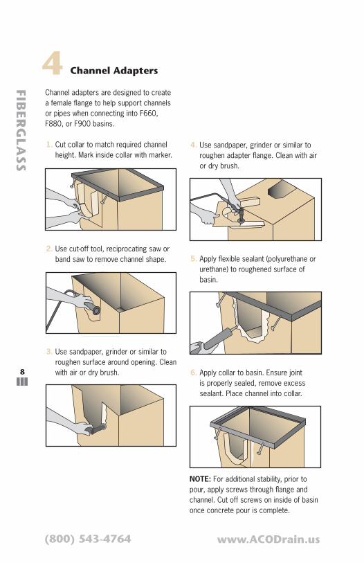
4Channel adapters are designed to create a female flange to help support channels or pipes when connecting into F660, F880, or F900 basins.
1. Cut collar to match required channel height. Mark inside collar with marker.
Channel Adapters
2. Use cut-off tool, reciprocating saw or band saw to remove channel shape.
3. Use sandpaper, grinder or similar to roughen surface around opening. Clean with air or dry brush.
4. Use sandpaper, grinder or similar to roughen adapter flange. Clean with air or dry brush.
5. Apply flexible sealant (polyurethane or urethane) to roughened surface of basin.
6. Apply collar to basin. Ensure joint is properly sealed, remove excess sealant. Place channel into collar.
NOTE: For additional stability, prior to pour, apply screws through flange and channel. Cut off screws on inside of basin once concrete pour is complete.

9
(800) 543-4764 www.ACODrain.us
FIBER
GLA
SS
Commercial Trench Drains
5 Pipe Connections - Vertical Outlet Adapters
Vertical outlets provide vertical bell end for easy attachment to drainage pipe.
1. Align adapter with appropriate area of channel. Mark inside collar with marker.
2. Use cut-off tool, reciprocating saw or band saw to remove marked shape.
3. Use sandpaper, grinder or similar to roughen surface around opening. Clean with air or dry brush.
4. Use sandpaper, grinder or similar to roughen adapter flange. Clean with air or dry brush.
5. Apply flexible sealant (polyurethane or urethane) to roughened surface of adapter.
6. Secure adapter to bottom of channel. Ensure joint is properly sealed, remove excess sealant. Place pipe into adapter.
NOTE: For additional stability, prior to pour, apply screws through flange and channel. Cut off screws on inside of channel once concrete pour is complete.

10
(800) 543-4764 www.ACODrain.us
FIBER
GLA
SS
1. Hold pipe adapter in required position, mark basin. Use cut-off tool to remove marked area.
Pipe Connections - Pipe Adapters
Pipe adapters are designed to provide a transition for 4”, 6” or 8” Schedule 40 pipe.
2. Use sandpaper, grinder or similar to roughen surface of basin and pipe adapter on flange. Clean with air or dry brush.
3. Apply flexible sealant (polyurethane or urethane) to roughened surface of basin.
4. Place pipe adapter on basin. Ensure joint is properly sealed, remove excess sealant. Drainage pipe fits over the pipe adapter.
NOTE: For additional stability, prior to pour, apply screws through flange and channel. Cut off screws on inside of basin once concrete pour is complete.
5

11
(800) 543-4764 www.ACODrain.us
FIBER
GLA
SS
Commercial Trench Drains
Lay channels in the excavated trench beginning at the outlet point; where catch basin/pipe is located.
1. Cut 2 x 4’s to appropriate width to span excavated trench or form boards
2. Attach 2 x 4’s to channels using 3/8” all-thread rod (attach at frame cross members using holes for grate bolts).
CAUTION: Do not over tighten, cross members may deform, causing problems fitting grates.
3. Place outlet channel (deepest or highest channel number) and ensure it is aligned properly. Fasten 2 x 4 to form boards or surrounding slab. This prevents movement or floating of channels during concrete pour.
4. If channels are to be sealed, lightly sand, then wipe clean next female collar and male end. Apply 1/8” bead of polyurethane joint sealant approximately 1” from end of channel.
5. To position next channel, slide male end into coupler end of previous channel. Push channels together until frames are flush. Smooth joint sealant with a putty knife, if used.
6. Nail or anchor 2 x 4 to form board or slab. Check level and straighten. Repeat until trench run is assembled.
7. Check security of 2 x 4’s; system will float in wet concrete. Reattach if necessary.
2 x 4 (anchoring fasteners to prevent floating)
Spacers allowconcrete surfacefinishing
Plywood toprevent concreteentering channel
Foam blockbracing
6 Positioning Channels - Hanging Method
12
(800) 543-4764 www.ACODrain.us
FIBER
GLA
SS
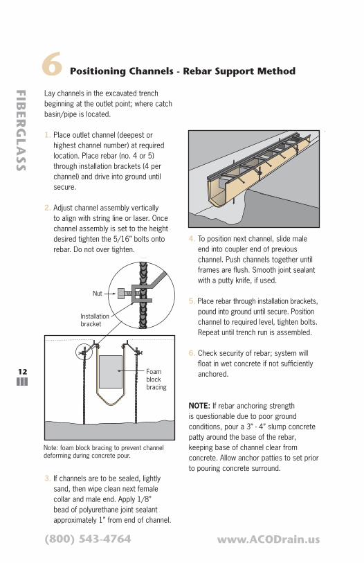
4. To position next channel, slide male end into coupler end of previous channel. Push channels together until frames are flush. Smooth joint sealant with a putty knife, if used.
5. Place rebar through installation brackets, pound into ground until secure. Position channel to required level, tighten bolts. Repeat until trench run is assembled.
6. Check security of rebar; system will float in wet concrete if not sufficiently anchored.
Lay channels in the excavated trench beginning at the outlet point; where catch basin/pipe is located.
1. Place outlet channel (deepest or highest channel number) at required location. Place rebar (no. 4 or 5) through installation brackets (4 per channel) and drive into ground until secure.
2. Adjust channel assembly vertically to align with string line or laser. Once channel assembly is set to the height desired tighten the 5/16” bolts onto rebar. Do not over tighten.
3. If channels are to be sealed, lightly sand, then wipe clean next female collar and male end. Apply 1/8” bead of polyurethane joint sealant approximately 1” from end of channel.
6 Positioning Channels - Rebar Support Method
Nut
Foam blockbracing
Installation bracket
Note: foam block bracing to prevent channel deforming during concrete pour.
NOTE: If rebar anchoring strength is questionable due to poor ground conditions, pour a 3” - 4” slump concrete patty around the base of the rebar, keeping base of channel clear from concrete. Allow anchor patties to set prior to pouring concrete surround.
13
(800) 543-4764 www.ACODrain.us
FIBER
GLA
SS
Commercial Trench Drains
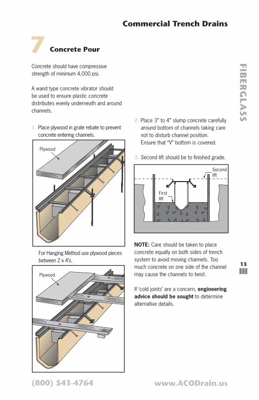
Concrete should have compressive strength of minimum 4,000 psi.
A wand type concrete vibrator should be used to ensure plastic concrete distributes evenly underneath and around channels.
1. Place plywood in grate rebate to prevent concrete entering channels.
Plywood
7 Concrete Pour
2. Place 3” to 4” slump concrete carefully around bottom of channels taking care not to disturb channel position. Ensure that “V” bottom is covered.
3. Second lift should be to finished grade.
Second lift
Firstlift
NOTE: Care should be taken to place concrete equally on both sides of trench system to avoid moving channels. Too much concrete on one side of the channel may cause the channels to twist.
If ‘cold joints’ are a concern, engineering advice should be sought to determine alternative details.
Plywood
For Hanging Method use plywood pieces between 2 x 4’s.
14
(800) 543-4764 www.ACODrain.us
FIBER
GLA
SS
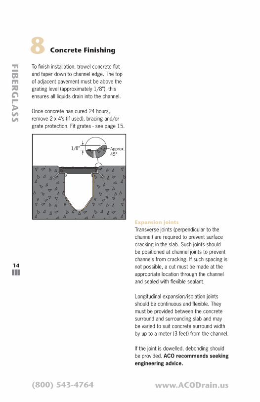
8 Concrete Finishing
1/8” Approx.45°
To finish installation, trowel concrete flat and taper down to channel edge. The top of adjacent pavement must be above the grating level (approximately 1/8”), this ensures all liquids drain into the channel.
Once concrete has cured 24 hours, remove 2 x 4’s (if used), bracing and/or grate protection. Fit grates - see page 15.
Expansion joints Transverse joints (perpendicular to the channel) are required to prevent surface cracking in the slab. Such joints should be positioned at channel joints to prevent channels from cracking. If such spacing is not possible, a cut must be made at the appropriate location through the channel and sealed with flexible sealant.
Longitudinal expansion/isolation joints should be continuous and flexible. They must be provided between the concrete surround and surrounding slab and may be varied to suit concrete surround width by up to a meter (3 feet) from the channel.
If the joint is dowelled, debonding should be provided. ACO recommends seeking engineering advice.
15
(800) 543-4764 www.ACODrain.us
FIBER
GLA
SS
Commercial Trench Drains
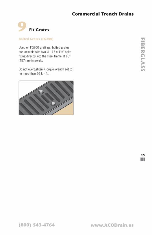
9 Fit Grates
Bolted Grates (FG200)
Used on FG200 gratings, bolted grates are lockable with two ½ - 13 x 1½” bolts fixing directly into the steel frame at 18” (457mm) intervals.
Do not overtighten. (Torque wrench set to no more than 26 lb - ft).

16
(800) 543-4764 www.ACODrain.us
FIBER
GLA
SS
10 Final Inspections
1. Remove any debris in the system and grate rebate. Ensure outlet pipes are clear.
2. Install trash baskets in catch basins, if required.
3. Flush trench run to check for pipe work blockages, unblock if necessary.
4. Empty trash buckets and clean out pipe connections, if necessary. Replace trash buckets.
5. Install gratings in proper position ensuring they are securely locked down. See page 15 for full details.
Drainage system is now ready for use.

17
(800) 543-4764 www.ACODrain.us
FIBER
GLA
SS
Commercial Trench Drains
Regular inspections of the trench drain are recommended. Frequency will depend on local conditions and environment, but should be at least annually.
Inspections should cover:
• Grates and lockings
• Catch basins and trash buckets
• Concrete surround and adjacent paving
All items should be inspected for damage, blockage or movement. Compare with site drawings if necessary.
1. Remove grates - see pg 15 for details
2. Remove debris from channel
3. Flush channels with water or high pressure washer
4. Repair damaged surfaces, if necessary, with an appropriate ACO repair kit
5. Empty trash buckets and clean out pipe connections
6. Re-install trash buckets
7. Re-install grates, ensuring they are locked in place.
Systems with grates that have wide slots may be cleaned with the use of pressured water applied through the grate — debris will be washed to the catch basin for removal. (Empty and replace trash bucket).
11 Maintenance


