Fiberless Coupled Tiles for a High Granularity Scintillator-SiPM Calorimeter Rick Salcido Rick Salcido Northern Illinois University Northern Illinois University November 14, 2009 November 14, 2009 Prairie Section of the American Physical Society Inaugural Meeting November 12-14, 2009 University of Iowa in Iowa City, IA
Transcript
Fiberless Coupled Tiles for a High
Granularity Scintillator-SiPM
CalorimeterRick SalcidoRick SalcidoNorthern Illinois UniversityNorthern Illinois University
November 14, 2009November 14, 2009Prairie Section of the American Physical Society
Inaugural Meeting November 12-14, 2009
University of Iowa in Iowa City, IA
CALICE Prototype DetectorThe CALICE detector is an example of a highly
granular scintillator-based hadronic calorimeter
which uses Silicon Photo Multipliers as readouts
Event Display showing 32 GeV Muons in Fermilab test-beam.
The highly granular design allows viewing of single particle tracks. Important parts of a detector are
Integrated Readout Layer (IRL) – Cost Efficient Proof of Principal
4
Scintillator Previous tile design
required wavelength shifting (WLS) fiber optic; technique used since the 80's with larger photo-multiplier tubes (PMTs)
New fiber-less tile design with concave dimple and surface mount SiPM
Concave dimple creates the uniform flat response
When a charged particle, such as a muon, passes through scintillating material, an electron in the material is promoted to a higher energy level and quickly falls back to its ground state emitting a photon of light. The photon eventually gets detected by the SiPM
5
Silicon Photo Multiplier (SiPM)
Advantage in that SiPMs are insensitive to magnetic fields
High Voltage is “low” compared to dynodes of a photo-multiplier tube (PMT), Voltage range 30 – 70 V
SiPMs are small and naturally lend themselves to compact calorimeters
Detection Efficiency acceptance greater than PMT
6
SiPM operation
Reverse bias applied
Active area: 1mm2 containing many avalanche photodiodes (APDs)
APDs amplify photocurrent
Applied reverse bias larger than breakdown -> E field large resulting in huge gain
Ionization – e-hole pair accelerated by high E field
Avalance Multiplication – carriers accelerated producing more carriers
Quenched Gieger Mode
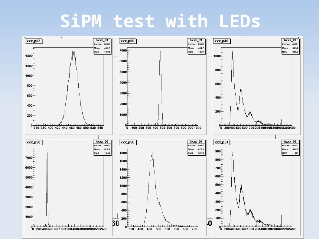
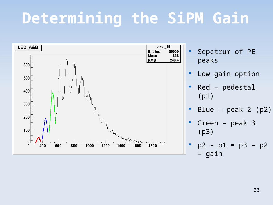
Photo-electron spectrum using 2 calibration LEDs
7
8
Dimpled Tiles Plots of various concavities
Compared with flat tile
9cm2, 5mm thick. 60% concavity optimal
3.375 mm concavity gives most uniform response
blue diamond – flat tileblue circle – 2.5 mm concavityorange triangle – 3.06 mm concavitylight blue square – 3.375 mm concavity
9
2D Plots
Flat Cell Response
Dimpled Cell Response
10
Building up...
Leading up to a large calorimeter, detection takes place not with one tile, but many
Tiles placed together to make larger mega-tile
Two holes required to mount on board
11
Integrated Readout Layer (IRL) 64 SiPM slots
Each Channel has High and low gain option
8 calibration LED slots
Each SiPM coupled fiberlessly to individual scintillating tile
3 SiPMs tested on this board
Other boards and SiPMs under examination now
12
Conclusion
Work Underway to prototype a highly granular, easily built scintillator-SiPM calorimeterSiPMs successfully fiberlessly coupled to scintillator cellsDimpled cells shown to have uniform response to radioactive sourcesPrototype IRL built and under evaluation; future beam tests and realistic calorimeter prototypes are planned
13
References
“Directly Coupled Tiles as Elements of a Scintillator Calorimeter with MPPC Readout”
Nuclear Instruments and Methods in Physics Research Section A
Volume 605, Issue 3, 1 July 2009, pgs 277-281 http://www.nicadd.niu.edu/~psalcido/605.277.2009.pdf