49
Fibre Connector Inspection & Cl i & Cleaning d b David Zambrano

Fibre Connector Inspection& Cl i& Cleaning
d bDavid Zambrano

Inspect Before You Connectsm
• Inspection Overview
• Fiber Optic Connectors
• Contamination
• Simple Solution
• Standards Update
• Extras – MTP/MPO connector inspection

Inspection Overview –Microscopes
DIRECT-VIEW SCOPE BENCH SCOPE
DIGITAL PROBEPROBE SCOPE & DISPLAYS

Part I: Fibre Optic ConnectorsPart I: Fibre Optic Connectors

Causes of Network Failure
In a recent study by NTT-Advanced Technology, 98% of installers (blue) and 80% of network owners (red) reported that issues with connector contamination was the greatest cause of network failurecontamination was the greatest cause of network failure.

Fiber Connectors Are EverywhereFiber optic connectors are common throughout the network, and they give you the power to add, drop, move and change the network.
BuildingsLocal Convergence Point
Network Access Points
CO/Head End
Multi-home UnitsResidential
Feeder Cables
Distribution Cables
Drop CablesDrop Cables

Anatomy of Fiber ConnectorLight is transmitted and retained in the “CORE” of the optical fiber by total internal reflection.
Singlemode Fiber StructureSinglemode Fiber StructureSinglemode fibers carry a single ray of light, making them better in retaining the fidelity of light over long Fiber End Face Viewfidelity of light over long distances.
There are 3 major ZONESth d f th t
FERRULE
Fiber End Face ViewZONE C
on the end face that are used to define the level of impact contamination may have on signal
CLADDING
ZONE B
have on signal performance. Particles closer to Zone A (Core) will have more impact than
CORE
ZONE A
those farther out.

Simplex vs. Multi‐fiber ConnectorsSIMPLEX CONNECTOR RIBBON CONNECTOR
White ceramic or metallic ferrule One fiber per connector Common types include SC, LC, FC,
Multiple fibers in linear array (8, 12, 24, 48, 72, etc.) in single connector providing Common types include SC, LC, FC,
E2000 and ST high-density connectivity Includes MPO or MTP®

Focused On the ConnectionBulkhead Adapter
Fiber ConnectorFiber
Ferrule
Alignment Sleeve
Alignment Sleeve
Physical Contact
Fiber connectors are widely known as the WEAKEST AND MOST PROB EMATIC i i h fib kPROBLEMATIC points in the fiber network.

What Makes a GOOD Fiber Connection?Connection?
The 3 basic principles that are critical to achieving an efficient fiber optic connection are “The 3 P’s”:
P f t C Ali tLight Transmitted
• Perfect Core Alignment
• Physical ContactCore
• Pristine Connector Interface
Cladding
CLEAN
Today’s connector design and production techniques have eliminated most of the challenges to achieving Core Alignment and Physical Contact.
Part II: ContaminationPart II: Contamination
Understanding the effect on signal performance

What Makes a BAD Fiber Connection?Connection?
Today’s connector design and production techniques have eliminated most of the challenges to achieving CORE ALIGNMENT and PHYSICAL CONTACT.
What remains challenging is maintaining a PRISTINE END FACE. As a result, CONTAMINATION is the #1 source of troubleshooting in optical networks.
• A single particle mated into the core of a fiber
g p
Back Reflection Insertion LossLight
can cause significant back reflection, insertion loss and even equipment Core
g
damage.
• Pressure is approx 50kpsi – similar to water jet
DIRT
Cladding
jcutters
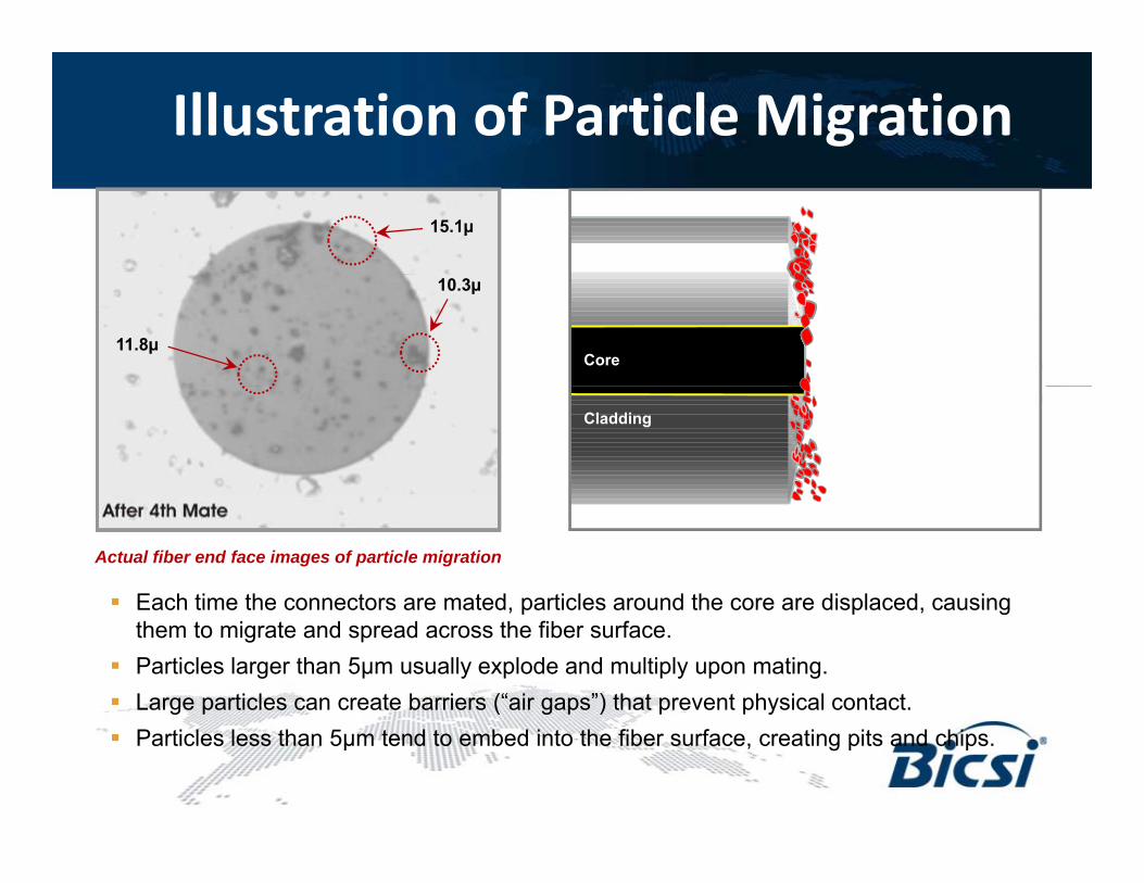
Illustration of Particle Migration
15.1µ
11.8µ
10.3µ
Core
Cladding
Each time the connectors are mated, particles around the core are displaced, causing
Actual fiber end face images of particle migration
Each time the connectors are mated, particles around the core are displaced, causing them to migrate and spread across the fiber surface.
Particles larger than 5µm usually explode and multiply upon mating. Large particles can create barriers (“air gaps”) that prevent physical contact. Particles less than 5µm tend to embed into the fiber surface, creating pits and chips.

Original OTDR Trace

OTDR Trace after cleaning connector at event 2at event 2

Types of ContaminationA fiber end face should be free of any contamination or defects, as shown below:
SINGLEMODE FIBER
Common types of contamination and defects include the following:
Dirt Oil Pits & Chips Scratches

Where is it? – Proliferation of DirtThere are a number of different sources where dirt and other particles can contaminate the fiber.
• Test Equipment
• Dust Caps
• Bulkheads
• People
• Environment• Environment
Connectors and ports on test equipment are mated frequently and are highly likely to become contaminated. Once contaminated, this equipment will often cross-contaminate the network connectors and ports being tested.
Inspecting and cleaning test ports and leads before testing network connectors prevents cross-contamination.

Part III: Simple SolutionPart III: Simple Solution
Inspect Before You Connect

Inspect Before You Connectsm
Follow this simple “INSPECT BEFORE YOU CONNECT” process to ensure fiber end faces are clean prior to mating connectors.p g

Inspect, Clean, Inspect, and Go!Fiber inspection and cleaning are SIMPLE steps with immense benefits.
44 Connect22 Clean11 Inspect 33 Inspect
■ If the fiber is clean■ If the fiber is dirty■ Use a probe ■ Use a probe ■ If the fiber is clean, CONNECT the connector.
NOTE: Be sure to inspect both sides
■ If the fiber is dirty, use a simple cleaning tool to CLEAN the fiber surface.
■ Use a probe microscope to INSPECT the fiber.
– If the fiber is dirty, go to step 2,
■ Use a probe microscope to RE-INSPECT (confirm fiber is clean). p
(patch cord “male” and bulkhead “female”) of the fiber interconnect.
g pcleaning.
– If the fiber is clean, go to step 4, connect.
– If the fiber is still dirty, go back to step 2, cleaning.
– If the fiber is clean, go to step 4 connectgo to step 4, connect.

Procedure Example – AT&T• This workflow chart comes
from AT&T Document ATT-TP-76461 titled “AT&T Fiber Optic Connector and Adapter Inspection and Cleaning Standards” - in the public domain.
• AT&T’s procedures call for continual inspection and cleaning.
• AT&T procedures starts with dry cleaning
t f th fi tconnectors for the first three cleanings.

Inspect and Clean Both Connectors in Pairs!in Pairs!
Inspecting BOTH sides of the connection is the ONLY WAY to ensure that it will be free of contamination and defects.
Bulkhead (“Female”) InspectionPatch Cord (“Male”) Inspection
Patch cords are easy to access and view compared to the fiber inside the bulkhead, which is frequently overlooked. The bulkhead side may only be half of the connection but it is far more likely to be dirty and problematicthe connection, but it is far more likely to be dirty and problematic.

Proactive vs. Reactive InspectionPROACTIVE INSPECTION:
Visually inspecting fiber
REACTIVE INSPECTION:Visually inspecting fiber connectors y p g
connectors at every stage of handling BEFOREmating them.
Connectors are much easier to
y p gAFTER a problem is discovered, typically during troubleshooting.
By this time connectors and otherConnectors are much easier to clean prior to mating, before embedding debris into the fiber.
By this time, connectors and other equipment may have suffered permanent damage.
Dirty Fiber PRIOR to MatingFiber AFTER Mating and Numerous Cleanings
Dirty Fiber PRIOR to MatingFiber AFTER Cleaning
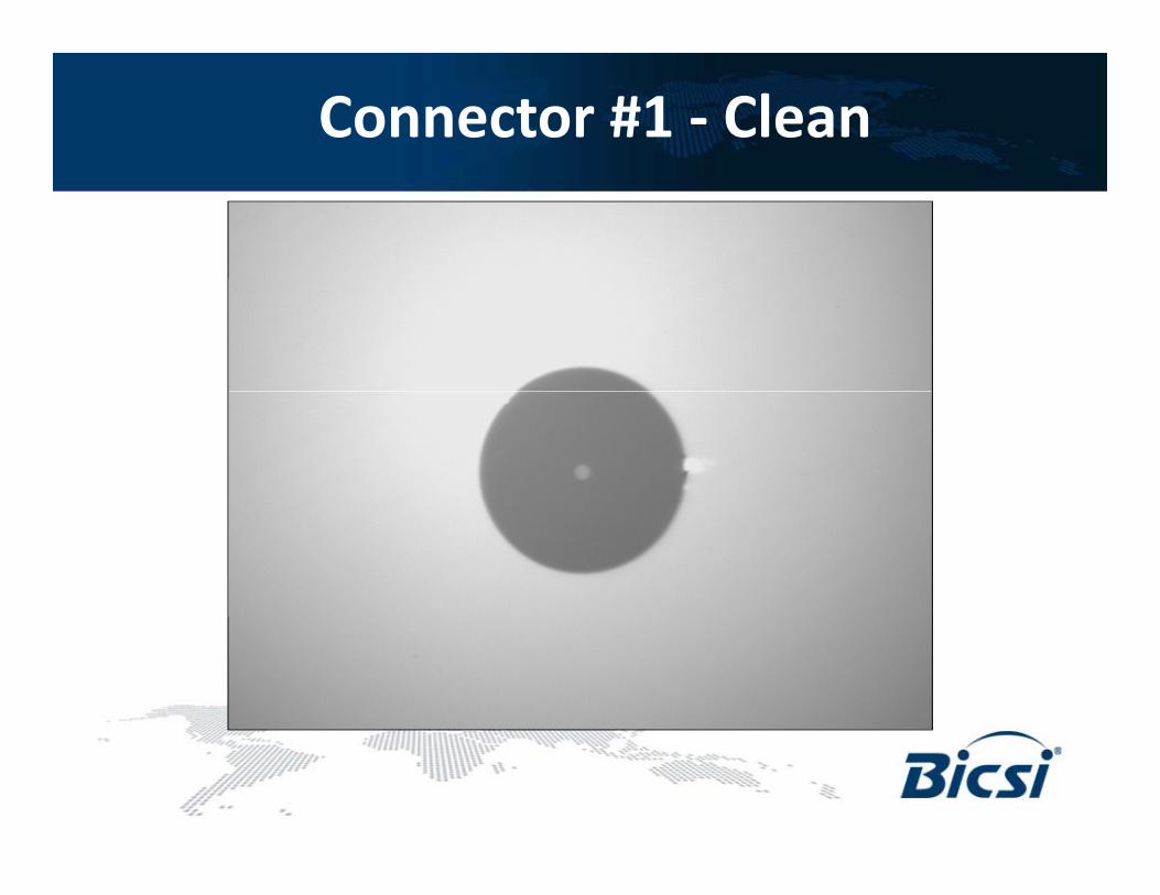
Connector #1 ‐ Clean

Connector #1 – Loose ContaminationContamination

Connector #2 ‐ Clean

Connector #2 – After One ConnectionConnection

Connector #2 – After Repeated CleaningCleaning

Connector #1 – After One ConnectionConnection

Connector #1 – After Repeated CleaningCleaning

Part IV: Standards UpdatePart IV: Standards Update

Standards and ZonesIEC 61300-3-35 – “Fibre Optic Connector Endface Visual and Automated Inspection” has recently been published as an interoperability standard for
t f t d
ZONES are used to prioritize evaluation criteria.
connector manufacturers and users.
Zone A: Core ZoneZone B: Cladding ZoneZone C: Adhesive ZoneZone D: Contact Zone
Different failure criteria for defects and t h ifi d f hscratches are specified for each zone:
• Quantity and Size• Location relative to core
Zone A
Zone D
Zone B
Zone D

Recommended Acceptance Criteria for SM‐UPCConnectors (IEC 61300‐3‐35)( )
Zone Name(diameter) Scratches Defects(diameter) Scratches Defects
A, Core Zone(0-25μm) none none
B, Cladding Zone(25-120μm) none > 3μm width
no limit < 2μm5 from 2 - 5μm
none > 5μmμ
C, Adhesive Zone(120-130μm) no limit no limit( μ )
D, Contact Zone(130-250μm) no limit none > 10μm( μ )

Recommended Acceptance Criteria for SM‐APC Connectors (IEC 61300‐3‐35)( )
Zone Name(diameter) Scratches Defects(diameter) Scratches Defects
A, Core Zone(0-25μm) < 4 scratches none
B, Cladding Zone(25-120μm) none > 3μm width
no limit < 2μm5 from 2 - 5μm
none > 5μmμ
C, Adhesive Zone(120-130μm) no limit no limit( μ )
D, Contact Zone(130-250μm) no limit none > 10μm( μ )

Recommended Acceptance Criteria for MM‐PC Connectors (IEC 61300‐3‐35)Connectors (IEC 61300 3 35)
Zone Name(diameter) Scratches Defects(diameter) Scratches Defects
A, Core Zone(0-65μm) none > 3μm width 4 5μm
none > 5μm
B, Cladding Zone(65-120μm) none > 5μm width
no limit < 2μm5 from 2 - 5μm
none > 5μmμ
C, Adhesive Zone(120-130μm) no limit no limit( μ )
D, Contact Zone(130-250μm) no limit none > 10μm( μ )
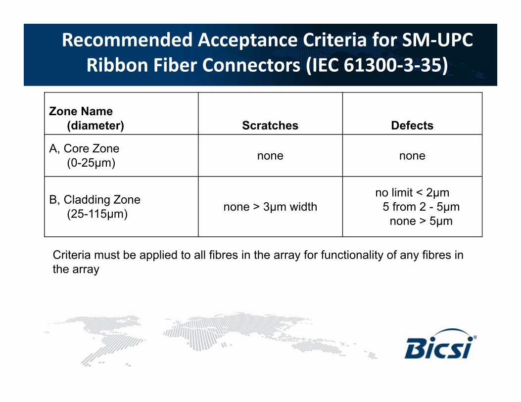
Recommended Acceptance Criteria for SM‐UPC Ribbon Fiber Connectors (IEC 61300‐3‐35)( )
Zone Name(diameter) Scratches Defects(diameter) Scratches Defects
A, Core Zone(0-25μm) none none
B, Cladding Zone(25-115μm) none > 3μm width
no limit < 2μm5 from 2 - 5μm
none > 5μmμ
Criteria must be applied to all fibres in the array for functionality of any fibres in the array

Recommended Acceptance Criteria for MM‐PC Ribbon Fiber Connectors (IEC 61300‐3‐35)( )
Zone Name(diameter) Scratches Defects(diameter)
A, Core Zone(0-65μm) none > 3μm width 4 5μm
none > 5μm
B, Cladding Zone(65-115μm) none > 5μm width
no limit < 2μm5 from 2 - 5μm
none > 5μm
Criteria must be applied to all fibres in the array for functionality of any fibres in the array

Where is IEC‐61300‐3‐35 Referenced?• TIA‐568‐C.0
– Referenced in test procedures• TIA 526 7 / IEC 61280 4 1• TIA‐526‐7 / IEC 61280‐4‐1
– Insertion loss testing of multimode fiber optic cabling• TIA‐526‐14B / IEC 61280‐4‐2
– Insertion and return loss testing of singlemode fiber optic cablingg g p g• ISO/IEC 11801
– References ISO/IEC 14763‐3 for all fiber testing• ISO/IEC 14763‐3
i fib i bli i i k– Testing fiber optic cabling in premises networks• IEC 61280‐4‐4 Ed.2
– PMD testing of installed fiber optic cabling• IEC 61757‐1IEC 61757 1
– International Standard for fiber optic sensors• ITU‐T G.650.3
– ITU Recommendation for fiber characterization• Purchasing specifications & work instructions

Fibre Test Standards for the PremiseOverview: TIA 568 C 0Overview: TIA‐568‐C.0
• “The foundation for premises telecommunications cabling infrastructure”
• Includes cabling transmission performance and test requirementsperformance and test requirements for BOTH twisted-pair and Optical Fibre
• Includes test guidelines that are described in an informative annexdescribed in an informative annex• Tier 1 Certification• Extended Testing (Tier 2)
• Next release is scheduled for release later this yearlater this year

568‐C and Connector QualityyThe test procedures specified by 568-C require tools and procedures for ensuring connector quality• End faces on test cords shall be accordance to IEC 61300‐3‐35
• Use a microscope that is compatible with IEC 61300‐3‐35
• The microscope must use adapters that are compatible with connectors
p g q y
The microscope must use adapters that are compatible with connectors
• TIA‐526‐14‐B
Optical Power Loss Measurements of Installed Multimode Fiber Cable PlantOptical Power Loss Measurements of Installed Multimode Fiber Cable Plant
• TIA‐526‐7
Optical Power Loss Measurements of Installed Single‐Mode Fiber Cable PlantOptical Power Loss Measurements of Installed Single‐Mode Fiber Cable Plant
The next update of 568-C will include explicit details about the p pinspection requirements in Annex E (testing)

Summary
Connectors are valuable and essential, but they must be handled properly.
CONTAMINATION is the #1 source of troubleshooting in optical networks CONTAMINATION is the #1 source of troubleshooting in optical networks.
This challenge is easily overcome with proactive inspection and cleaning.
Visual inspection of fiber optic connectors with a microscope is the only way sua spect o o be opt c co ecto s t a c oscope s t e o y ayto determine if connectors are clean before they are mated.
Proactive inspection is easy, and the benefits are: Reduced Network Downtime– Reduced Network Downtime
– Reduced Troubleshooting– Optimized Signal Performance
Prevention of Network Damage– Prevention of Network Damage
Always “INSPECT BEFORE YOU CONNECT”

Backup slideMulti‐Fiber Push‐on/Pull‐off (MPO)
• Multiple fibres in linear array (more fibres in same space!)– 8,12,24,48, etc.
Multi Fiber Push on/Pull off (MPO)
, , , ,
– MTP is an enhanced MPO connector
• Often used in breakout cassetteOften used in breakout cassette
• Or used direct12 fibres (40G 4 lanes 8 active fibres)– 12 fibres (40G ‐ 4 lanes, 8 active fibres)
– 24 fibres (100G ‐ 10 lanes, 20 active fibres)

Backup slideApplication Specific Performance Requirementspp p q
Cable Type
Wavelength 1GBE 10GBE 40 /100GBE
Loss (dB) Length (m) Loss (dB) Length (m)
Loss (dB) Length (m)
OM1 850 2.6 275 2.4 33 n/a n/a1300 2.3 550 2.5 300 n/a n/a
OM2 8501300
3.62.3
550550
2.32.0
82300
n/an/a
n/an/a
OM3 850 4 5 1000 2 6 300 1 9 100OM3 8501300
4.52.3
1000550
2.62.0
300300
1.9n/a
100n/a
OM4 8501300
4.82.3
1100550
3.12.0
1100300
1.5n/a
150n/a
Note: Ethernet standards limit 1GBE to 550 m and 10GBE to 300m. Some vendors allow greater distances

Backup slide: Ribbon connector inspection
• MPO cassettes add connections and associated loss– One connector multiple fiber end‐faces – troubleshooting nightmare
Ribbon connector inspection
One connector, multiple fiber end faces troubleshooting nightmare in live network

Backup slide:Exponential ImpactExponential Impact
CONTAMINATION is the #1 source of troubleshooting in optical networks
Image property of CommScope
If a critical connection is affected, the impact can be exponential
Image property of CommScope

Backup slide:Data Centre – 40 or 100GBASE‐SR10Data Centre 40 or 100GBASE SR10
From the IEEE802.3ba StandardStandard
• Channel Insertion Loss 1.5dB, includes 150m of OM4 fibre (3.5dB/km at 850nm)
• Two MPO connectors – 8 or 20 fibres
• No margin for dirty connectors
• Huge challenges exist with insertion loss testing of multi fibre cables

Inspect Before You Connectsmp

Backup slideFibre Optic Cleaning
• Apply IBYC always!– Even with brand new patchords
Fibre Optic Cleaning
p
• Cleaning process– Start with dry cleaning
– If particles are stubborn, use a wet cleaning process• IPA not an ideal solvent
– Always finish up with dry cleaning!
D ’t l i t l (i i )• Don’t reuse your cleaning tools (i.e. wipes)
• Use the right tool for the jobUse the right tool for the job

Any questions?Any questions?Thank you!


