97
Field Testing and Troubleshooting of PON LAN Networks per IEC 61280‐4‐3 Jim Davis Regional Marketing Engineer Fluke Networks
Field Testing and Troubleshooting of PON LAN Networks per IEC 61280‐4‐3
Jim DavisRegional Marketing Engineer
Fluke Networks
Agenda• Inspection and Cleaning
– APC vs UPC• PON basics
– Wavelengths– Architecture
• Splitters• Loss Budget – how many Connectors/Splitters
– Setting a reference• Troubleshooting
– OTDR– Power Meter
• Document Results

INSPECTION, AND, IF NECESSARY, CLEANING (REPEAT AS NEEDED)

Inspect, Clean, Repeat
4
Video Microscope Brand new out of bag
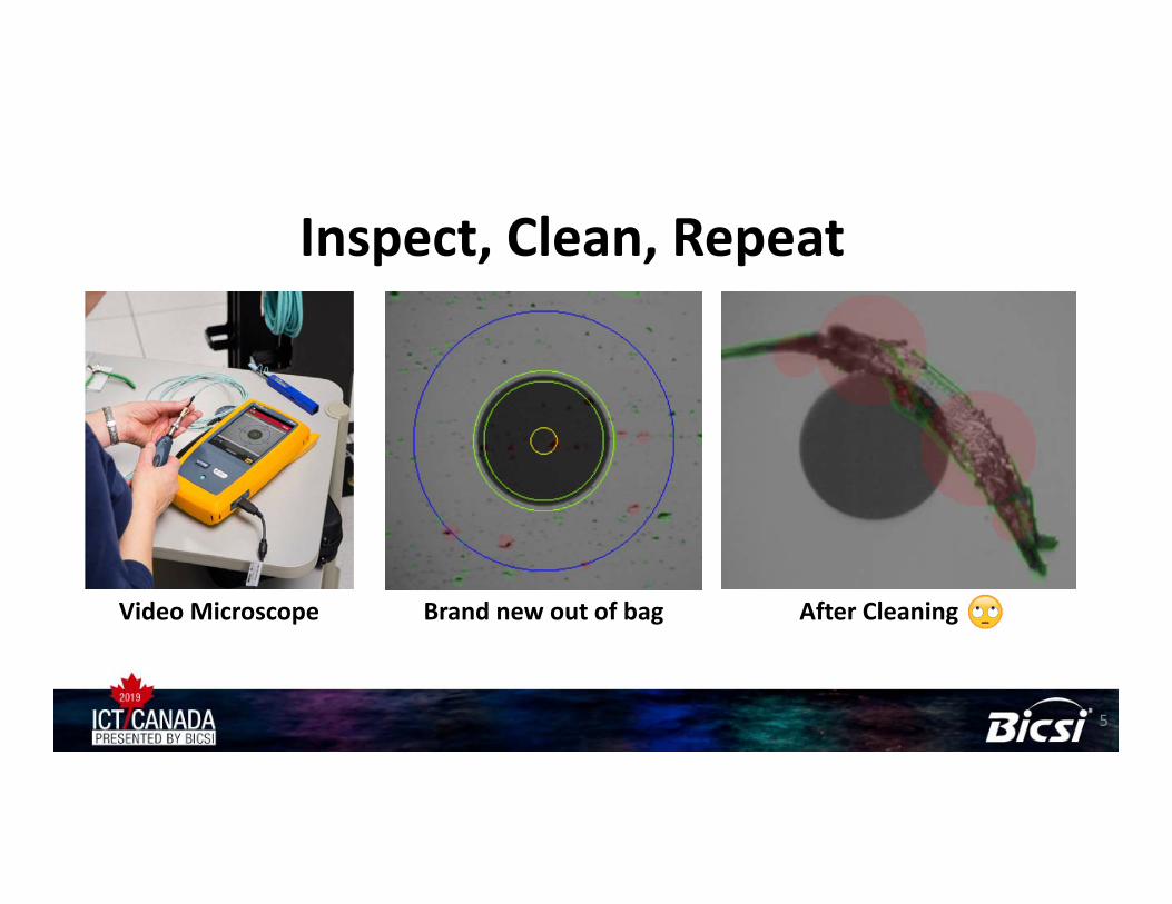
Inspect, Clean, Repeat
5
Video Microscope Brand new out of bag After Cleaning
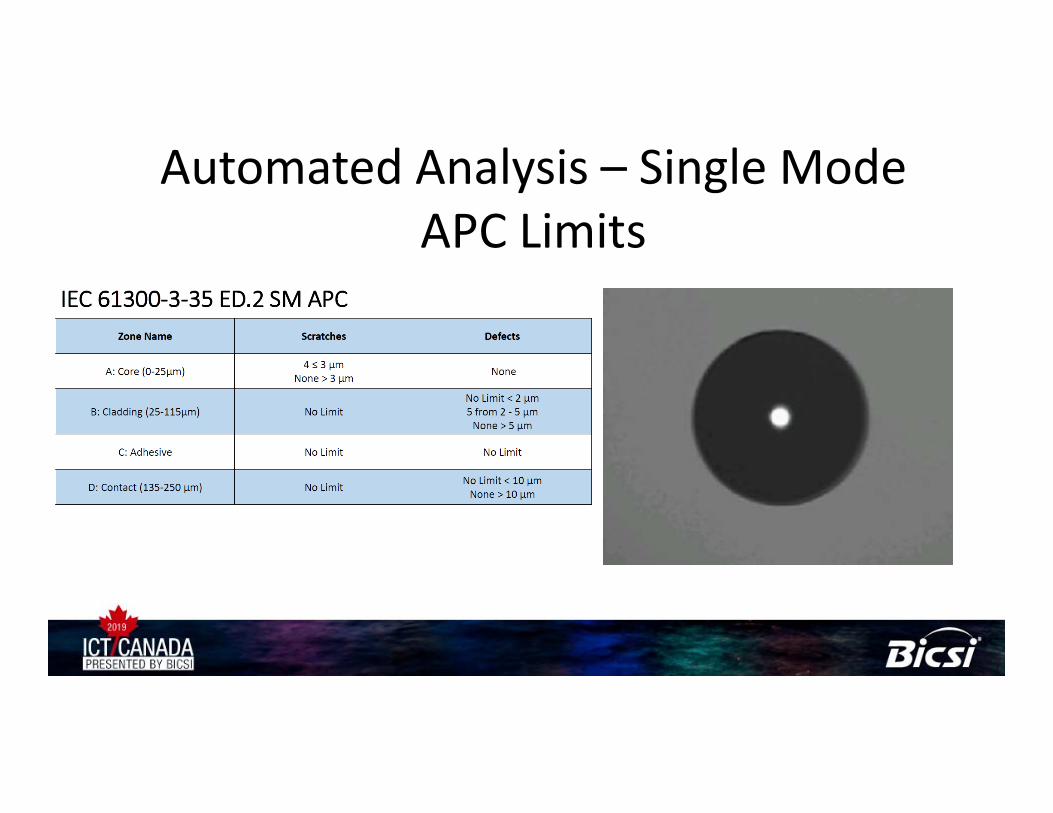
Automated Analysis – Single Mode APC Limits
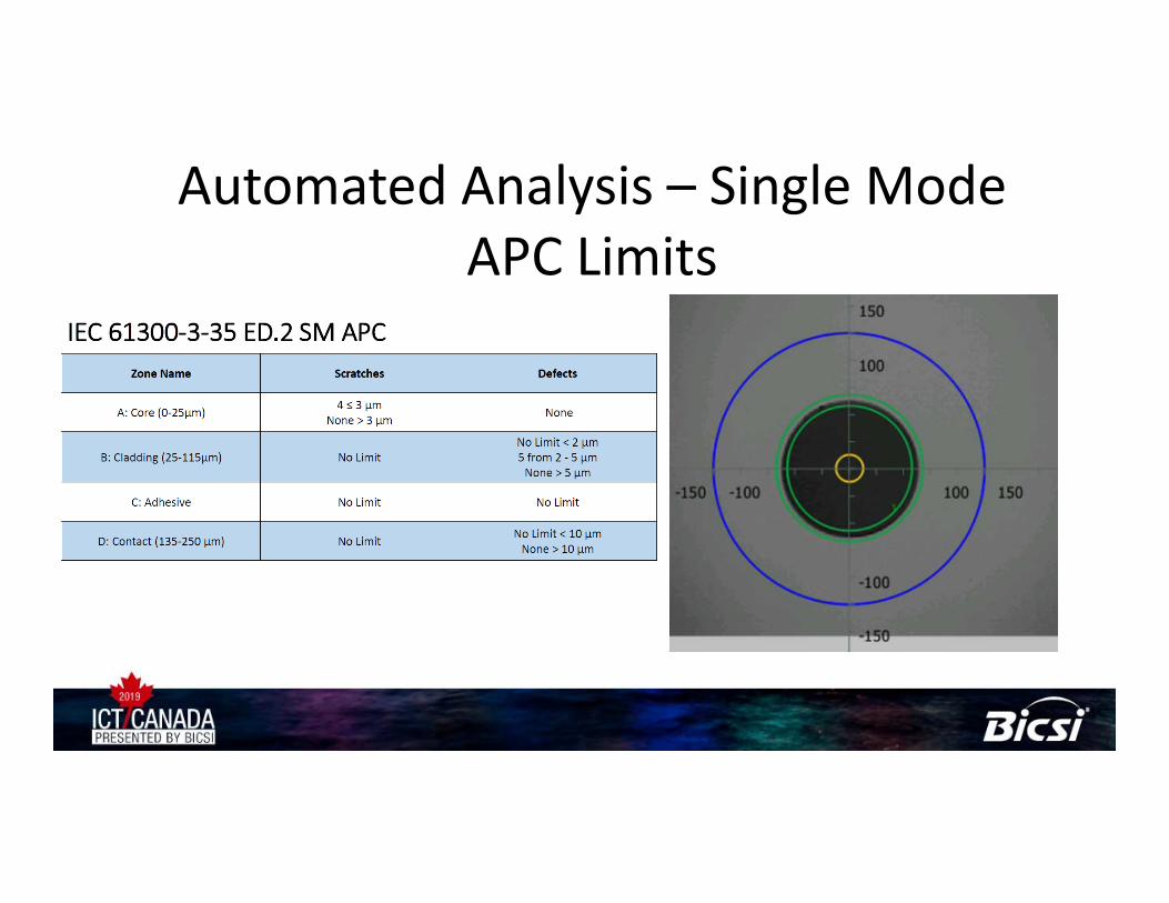
Automated Analysis – Single Mode APC Limits
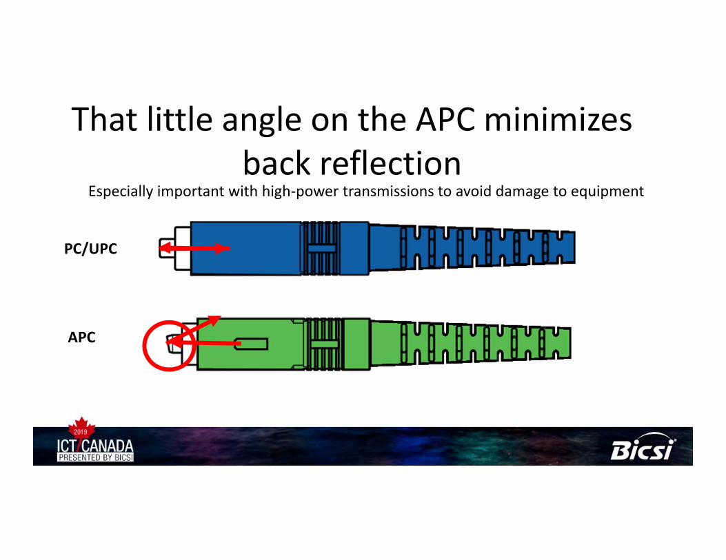
That little angle on the APC minimizes back reflection
Especially important with high‐power transmissions to avoid damage to equipment
PC/UPC
APC

APC Tips have a slight bend – these are SC

APC Connectors May Need a “Twist” to Show Up
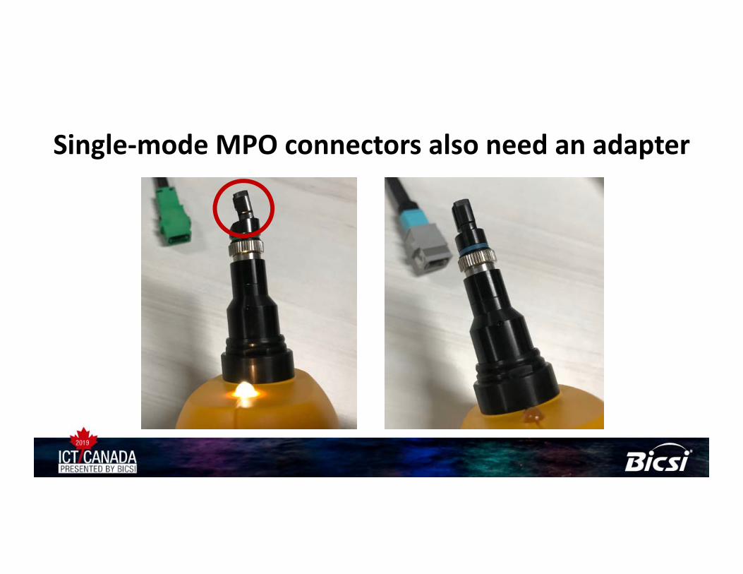
Single‐mode MPO connectors also need an adapter
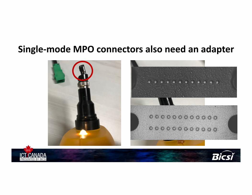
Single‐mode MPO connectors also need an adapter

Single‐mode MPO connectors also need an adapter
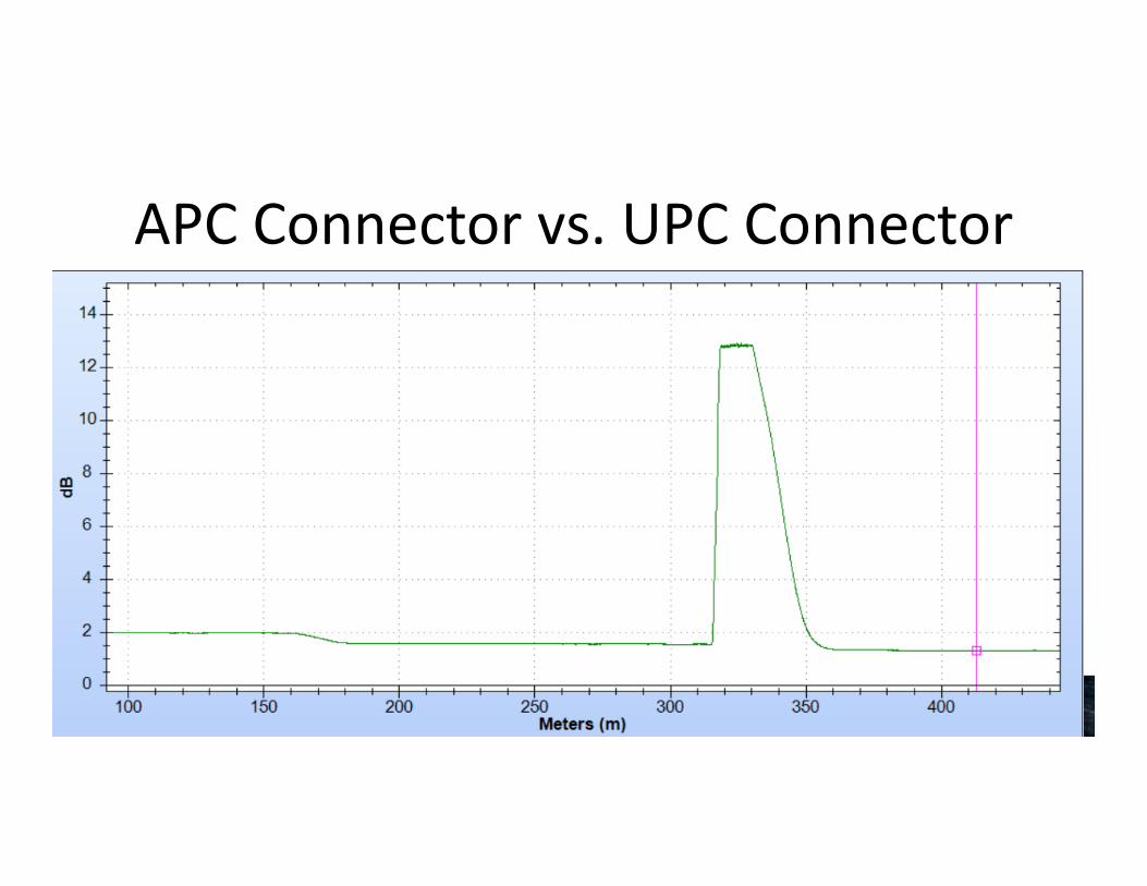
APC Connector vs. UPC Connector

APC Connector vs. UPC Connector

G‐PON• E‐PON and G‐PON – most common today with GPON standardized
through ITU‐recommendation series G.984.1 through G.984.4• 10G or XG‐PON, NG‐PON, NG‐PON2• TBD‐PON [Super‐PON]• FTTx• PON‐LAN• We don’t care what you put on the road – we want to make sure the
road is in good shape to support today’s applications– Loss Budgets, Distances, Reflectance limits may be tighter with future
versions

Traditional Network Design
Data Center
Building Distribution
Network Closet
Core
Aggregation
Access

PON Compare
ONT ONT
Splitter

What is GPON?
ONT ONT
Splitter
Operates as a single managed switch

‘basic’ PON architecture
Downstream2.54Gbps
Upstream1.25Gbps

PON LAN Layout
Fiber Distribution Hub (FDH)DataCenter/MDF Single Administration Point
Fiber Distribution Terminal (FDT)
Fiber Concentration Point (FC/FCP)

Basic PON LAN Layout
OLT goes here

Basic PON LAN Layout
OLT goes here
Fiber Distribution Hub

Basic PON LAN LayoutONT/ONU goes here
Fiber Distribution Hub (FDH)DataCenter/MDF Single Administration Point
Fiber Distribution Terminal (FDT)
Fiber Concentration Point (FC/FCP)

Basic PON LAN Layout
Fiber Distribution Hub (FDH)DataCenter/MDF Single Administration Point
Fiber Distribution Terminal (FDT)
Fiber Concentration Point (FC/FCP)

Basic PON LAN Layout
Fiber Distribution Hub (FDH)DataCenter/MDF Single Administration Point
Fiber Distribution Terminal (FDT)
Fiber Concentration Point (FC/FCP)

Basic PON LAN Layout
Fiber Distribution Hub (FDH)DataCenter/MDF Single Administration Point
Fiber Distribution Terminal (FDT)
Fiber Concentration Point (FC/FCP)

Basic PON LAN Layout
Fiber Distribution Hub (FDH)DataCenter/MDF Single Administration Point
Fiber Distribution Terminal (FDT)
Fiber Concentration Point (FC/FCP)
Basic PON LAN Layout
Fiber Distribution Hub (FDH)DataCenter/MDF Single Administration Point
Fiber Distribution Terminal (FDT)
Fiber Concentration Point (FC/FCP)

Basic PON LAN Layout
Fiber Distribution Hub (FDH)DataCenter/MDF Single Administration Point
Fiber Distribution Terminal (FDT)
Fiber Concentration Point (FC/FCP)

SPLITTERS – PUTTING THE PASSIVE IN PON

VFL Goes in – Light comes out on all ports

How does the data move?
OLT
ONT/ONU
OLT – Optical Line TerminalONU – Optical Network Unit (ONT – Optical Network Terminal)
1490 nm 1550 nm1310 nm
ONT/ONU
1.25Gbps UPSTREAM
2.54Gbps
2.54Gbps
Multiple Wavelengths One Fiber: Wave Division Multiplexing
2.54Gbps DOWNSTREAM

Multiple Wavelengths One FiberOLT
ONT/ONU
OLT – Optical Line TerminalONU – Optical Network Unit (ONT – Optical Network Terminal)
1490 nm
1550 nm 1310 nmCATV
Voice
DATA WDM Coupler

How does the data move upstream?Time Division Multiplexing: TDM
Source: University of Peshawar 2.54Gbps in a available to all ONTs downstream1.25Gbps upstream, however TDM is employed to deal with traffic

Splitters and Bandwidth• There is not a relationship between loss value and available bandwidth
• There is a relationship between number of users and available bandwidth
• GPON offers 2.54 Gig/sec downstream and 1.25 upstream
– The number of splits will not affect downstream speeds, it is broadcast
– Upstream speeds will be affected by the number of users and the applications they are using.
– Through DBA (Dynamic Bandwidth Allocation), the available bandwidth can be changed or assigned.
• Bandwidth can be allocated as needed to maintain a good customer experience

Multiple Wavelengths One Fiber –Redundancy
OLT
ONT/ONU
OLT – Optical Line TerminalONU – Optical Network Unit (ONT – Optical Network Terminal)
1490 nm 1550 nm1310 nm
ONT/ONU

Multiple Wavelengths One Fiber –Redundancy
OLT
ONT/ONU
OLT – Optical Line TerminalONU – Optical Network Unit (ONT – Optical Network Terminal)
1490 nm 1550 nm1310 nm
ONT/ONU

Splitters as the name suggests divide the light
• Think of a splitter like a “Y” on a garden hose– If you put a gallon of water into the
hose, you will get ½ gallon on each port– In optical power, that “loss” would be
expressed as 3 dB• And a little bit for the connectors more for
SC or LC connectors than a fusion splice• A 1 x 2 splitter should have about 3.5 dB of
loss

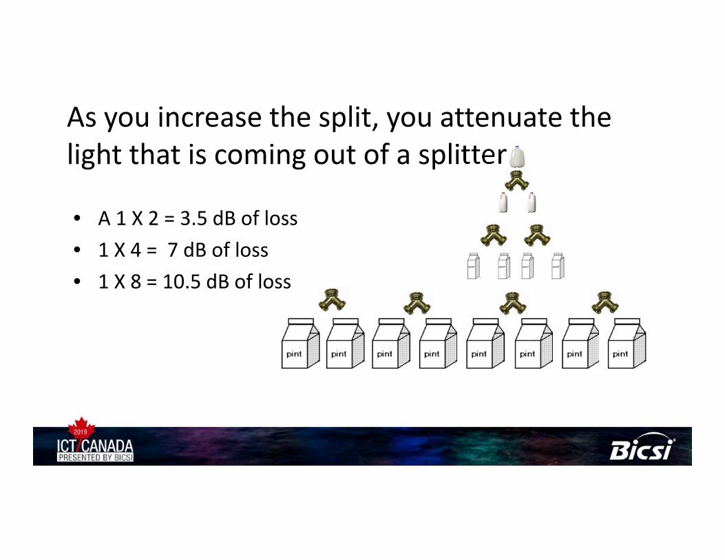
As you increase the split, you attenuate the light that is coming out of a splitter
• A 1 x 2 = 3.5 dB of loss• 1 x 4 = 7 dB of loss
As you increase the split, you attenuate the light that is coming out of a splitter
• A 1 X 2 = 3.5 dB of loss• 1 X 4 = 7 dB of loss• 1 X 8 = 10.5 dB of loss

As you increase the split, you attenuate the light that is coming out of a splitter
• A 1 X 2 = 3.5 dB of loss• 1 X 4 = 7 dB of loss• 1 X 8 = 10.5 dB of loss• 1 x 16 = 14 dB
2 x 8 1 x 16
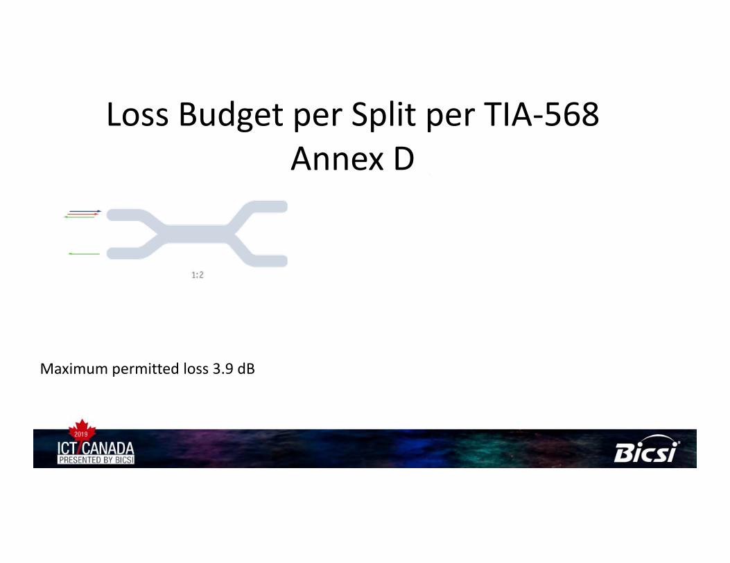
Maximum permitted loss 3.9 dB 7.3 dB 10.7 dB 14.1 dB
Loss Budget per Split per TIA‐568 Annex D

Under the Hood
PLC

TESTING OF PON NETWORKS

What To Test – Per IEC 61280‐4‐3• Single Stage Optical Distribution Network (ODN)• Multiple Stage ODN• Attenuation
– Light Source and Power Meter– 1310 and 1550 nm– OTDR (only in the upstream direction)

0
0.05
0.1
0.15
0.2
0.25
0.3
0.35
0.4
0.45
0.5
1271 1291 1311 1331 1351 1371 1391 1411 1431 1451 1471 1491 1511 1531 1551 1571 1591 1611
Attenu
ation (dB/km
)
Wavelength (nm)
Bend Detection and Future Proofing
Wavelengths are “bound” • If 1310 nm and 1550 nm pass, the others wavelengths will pass
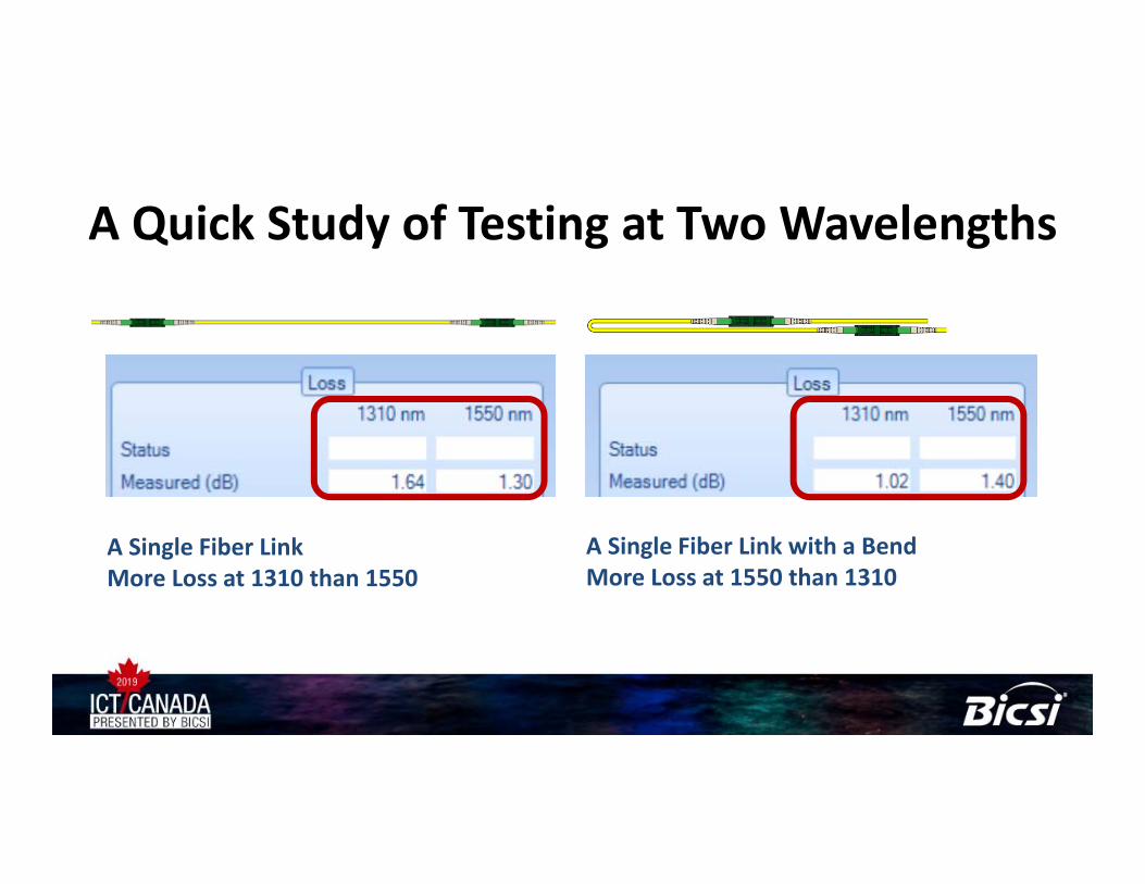
A Quick Study of Testing at Two Wavelengths
A Single Fiber LinkMore Loss at 1310 than 1550
A Single Fiber Link with a BendMore Loss at 1550 than 1310

A Quick Study of Testing at Two Wavelengths
A Single Fiber LinkMore Loss at 1310 than 1550
A Single Fiber Link with a BendMore Loss at 1550 than 1310

OTDR Trace Shows Location of Bend• But not at 1310 nm
1310 nm

OTDR Trace Shows Location of Bend• But not at 1310 nm
1550 nm

LOSS BUDGET CALCULATION

What loss budget to use when testing
• There can be different loss budgets that can be used– A Cabling limit, like the one called out in the IEC
standard• Cable + Connectors + Splitters
– An active equipment limit – depends on equipment
• Fixed value 27 dB
Cabling Standards:TIA 568
ISO 11801
Active Equipment:SensitivityTransmit Power

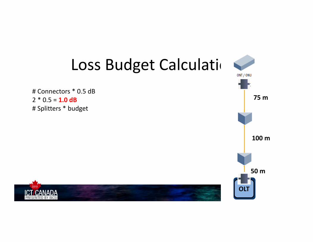
Loss Budget Calculation# Connectors * 0.5 dB2 * 0.5 = 1.0 dB# Splitters * budget1 X 4 Port = 7.3 dB1 X 8 Port = 10.7 dBKM of Fiber * 1 dB/Km (Tight buffered indoor)50 m + 100 m + 75 m = .225 dBTotal Loss Budget = 21.83 dB
50 m
100 m
75 m
4
8
OLT
Loss Budget Calculation# Connectors * 0.5 dB2 * 0.5 = 1.0 dB# Splitters * budget1 X 4 Port = 7.3 dB1 X 8 Port = 10.7 dBKM of Fiber * 1 dB/Km (Tight buffered indoor)50 m + 100 m + 75 m = .225 dBTotal Loss Budget = 21.83 dB
50 m
100 m
75 m
8
4
OLT

Loss Budget Calculation# Connectors * 0.5 dB2 * 0.5 = 1.0 dB# Splitters * budget1 X 4 Port = 7.3 dB1 X 8 Port = 10.7 dBKM of Fiber * 1 dB/Km (Tight buffered indoor)50 m + 100 m + 75 m = .225 dBTotal Loss Budget = 21.83 dB
50 m
100 m
75 m
8
4
OLT
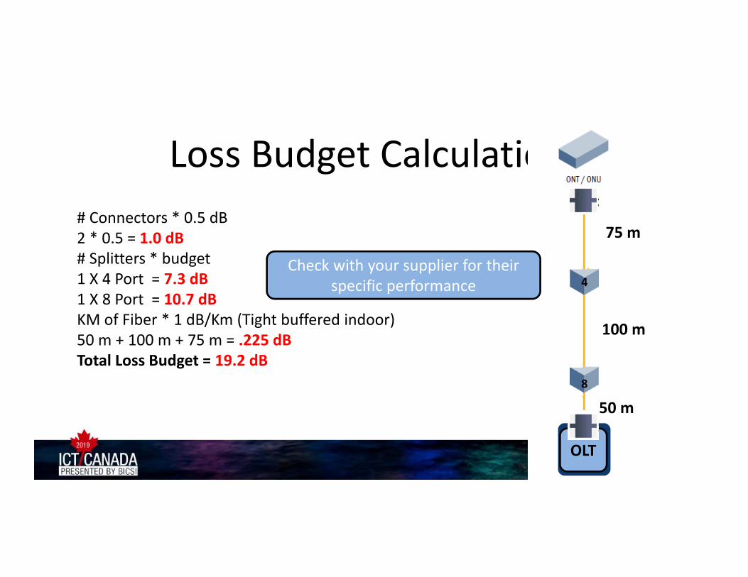
Loss Budget Calculation# Connectors * 0.5 dB2 * 0.5 = 1.0 dB# Splitters * budget1 X 4 Port = 7.3 dB1 X 8 Port = 10.7 dBKM of Fiber * 1 dB/Km (Tight buffered indoor)50 m + 100 m + 75 m = .225 dBTotal Loss Budget = 19.2 dB
50 m
100 m
75 m
8
4
OLT
Check with your supplier for their specific performance

Loss testing with minimal uncertaintyand maximum repeatability

• A One Jumper reference is called out in the standard• A Simple Light Source and Power Meter can be
used, or you can use common OLTS units, provided they can be put into a “Far End Source Mode”
Accurate Loss Testing will assure support for today’s and future network applications
59
Pressing this button again sets the singlemode port to 1310/1550 nm
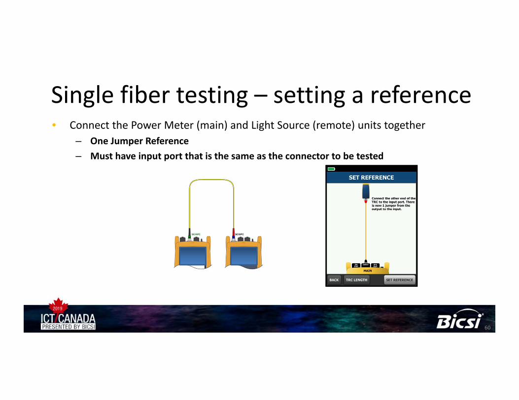
• Connect the Power Meter (main) and Light Source (remote) units together– One Jumper Reference– Must have input port that is the same as the connector to be tested
Single fiber testing – setting a reference
60

Test Reference Cord or Launch Fiber?• A Test Reference Cord is used for Loss Testing (OLTS) and is usually from 1 to 5 meters long
• A Launch Fiber or Dead Zone Eliminator and its friend, Receive Fiber or Tail Fiber, is used for OTDR testing and is usually 100 meters or longer

Test Reference Cord or Launch Fiber?• A Test Reference Cord is used for Loss Testing (OLTS) and is usually from 1 to 5 meters long
• A Launch Fiber or Dead Zone Eliminator and its friend, Receive Fiber or Tail Fiber, is used for OTDR testing and is usually 100 meters or longer
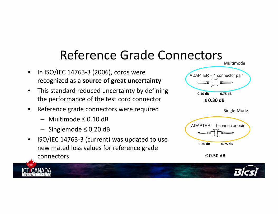
Reference Grade Connectors• In ISO/IEC 14763‐3 (2006), cords were
recognized as a source of great uncertainty• This standard reduced uncertainty by defining
the performance of the test cord connector• Reference grade connectors were required
– Multimode ≤ 0.10 dB– Singlemode ≤ 0.20 dB
• ISO/IEC 14763‐3 (current) was updated to use new mated loss values for reference grade connectors
0.75 dB0.10 dB
≤ 0.30 dB
0.75 dB0.20 dB
≤ 0.50 dB
Multimode
Single‐Mode
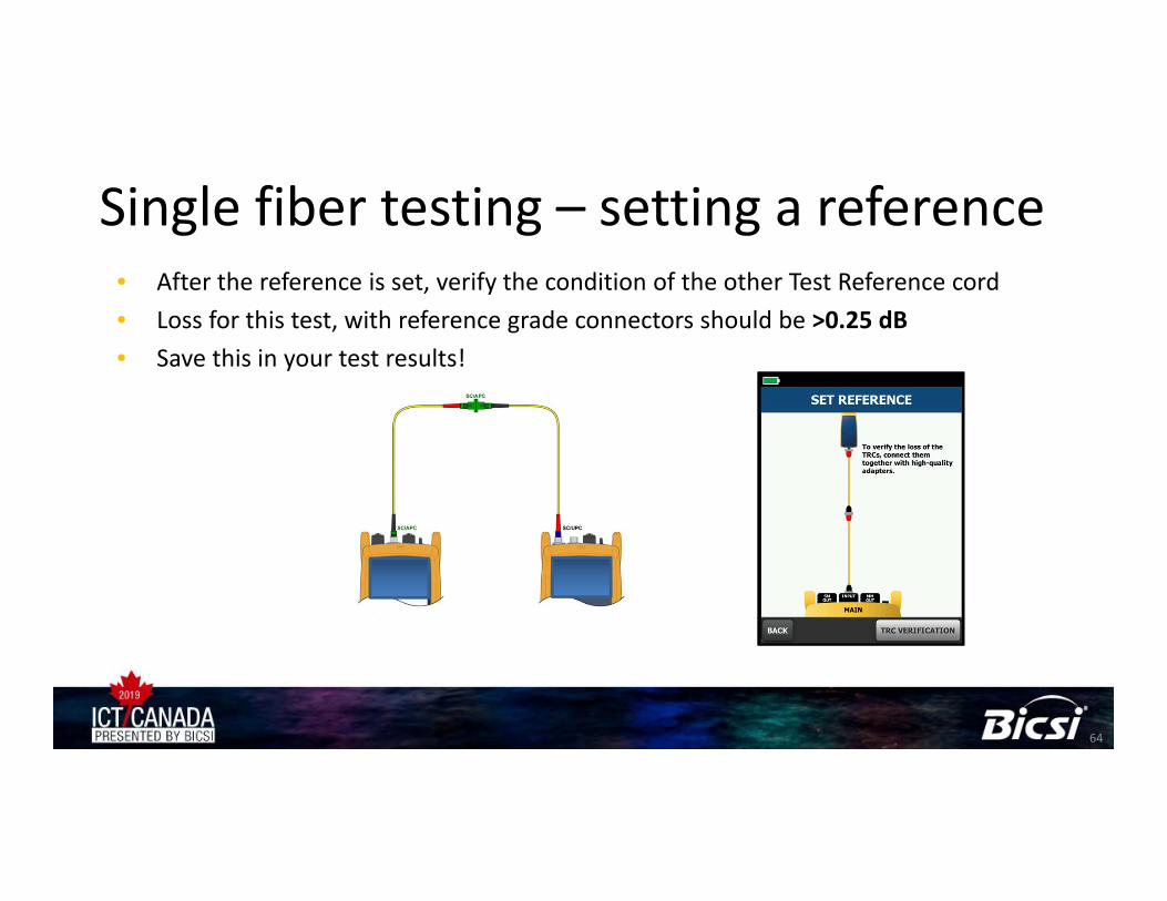
• After the reference is set, verify the condition of the other Test Reference cord• Loss for this test, with reference grade connectors should be >0.25 dB• Save this in your test results!
Single fiber testing – setting a reference
64
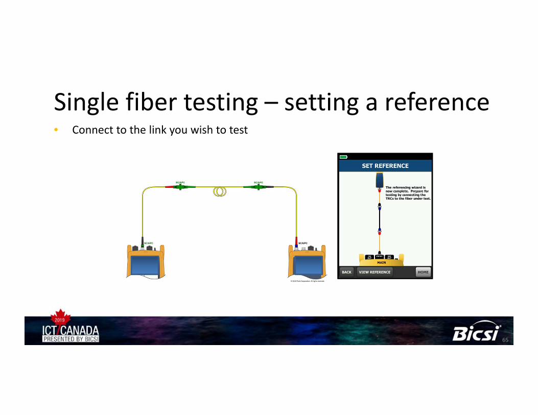
• Connect to the link you wish to test
Single fiber testing – setting a reference
65
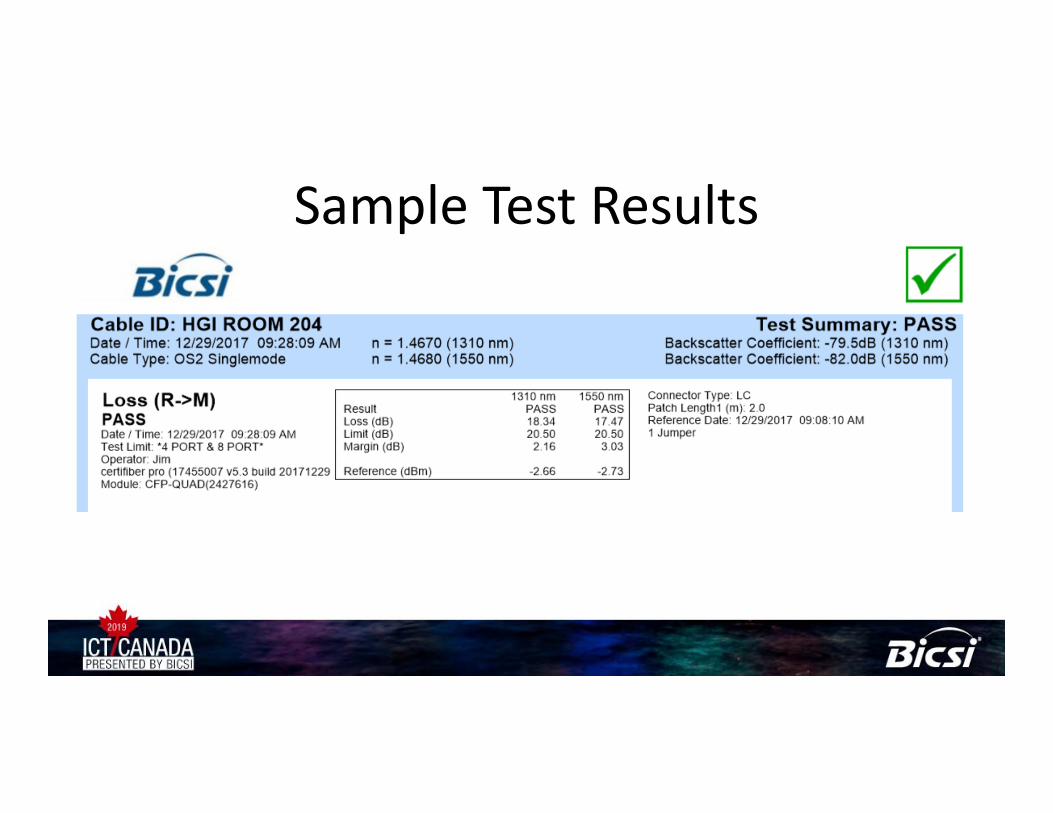
Sample Test Results

Sample Test Results ‐ Detail

Sample Test Results ‐ Detail

Alternate Loss Budget Calculation• Single Mode light sources are very powerful• Often, they can accept any amount of light down to a given level– Usually ‐27 dBm

Alternate Loss Budget Calculation• Single Mode light sources are very powerful• Often, they can accept any amount of light down to a given level– Usually ‐27 dBm

Alternate Loss Budget Calculation• Single Mode light sources are very powerful• Often, they can accept any amount of light down to a given level– Usually ‐27 dBm

Alternate Loss Budget Calculation• Single Mode light sources are very powerful• Often, they can accept any amount of light down to a given level– Usually ‐27 dBm

Alternate Loss Budget Calculation• Single Mode light sources are very powerful• Often, they can accept any amount of light down to a given level
– Usually ‐28 dBm– Rule of thumb – give yourself some margin 3 dB?
• When troubleshooting or testing with the OLT installed check for greater than ‐28 dBm in the POWER mode, not LOSS mode– ‐ 27 dBm is more power than ‐28 dBm– ‐29 dBm is less power than ‐28 dBm

Alternate Loss Budget Calculation• Single Mode light sources are very powerful• Often, they can accept any amount of light down to a given level
– Usually ‐28 dBm– Rule of thumb – give yourself some margin 3 dB?
• When troubleshooting or testing with the OLT installed check for greater than ‐28 dBm in the POWER mode, not LOSS mode– ‐ 27 dBm is greater than ‐28 dBm– ‐29 dBm is less than ‐28 dBm
• Loss is measured in dB– And should be a positive number

OTDR testing• Used to measure loss and reflectance of events• Upstream only• Requires a launch and tail cord
– Cords should have close backscatter coefficient to link under test
• Shall be capable of using a short pulse ≤ 20ns• Check the launch a receive cords prior to testing (B.6.2)
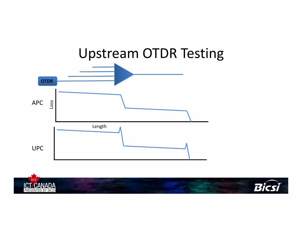
Upstream OTDR Testing
APC
UPC
Loss
Length
OTDR

Upstream OTDR Testing
APC
Loss
Length
OTDR

Upstream OTDR Testing
APC
Loss
Length
OTDR
8 Port Splitter
4 Port Splitter

Upstream OTDR Testing – If you are connected to an OLT there may be a reflective event at the end
APC
Loss
Length
OTDR
8 Port Splitter
4 Port Splitter

Downstream Testing
APC
UPC
OTDR
Loss
Length

Downstream Testing
APC
OTDR
Loss
Length
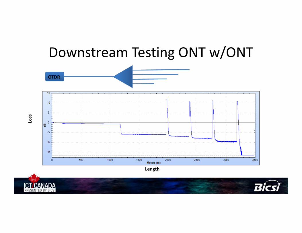
Downstream Testing ONT w/ONTOTDR
Loss
Length

TROUBLESHOOTING LINKS
Did you try rebooting?
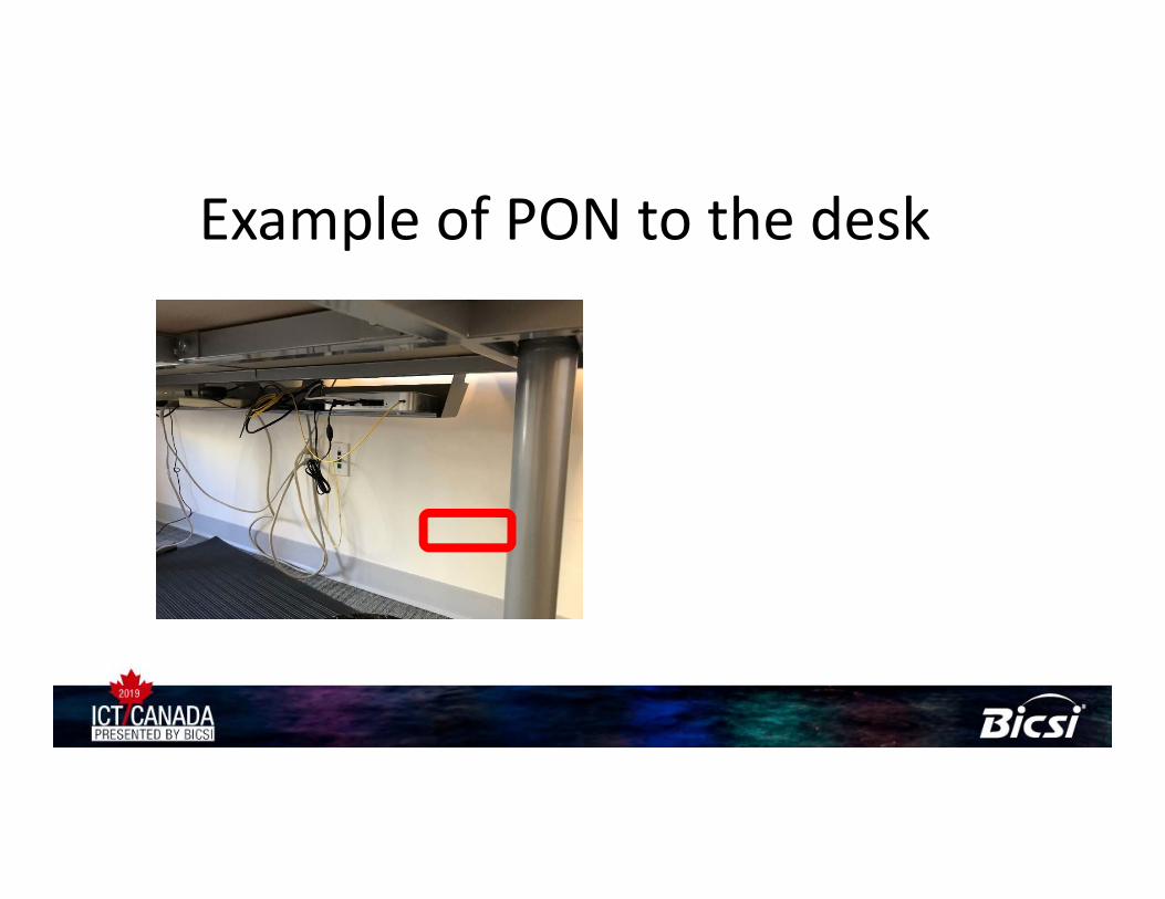
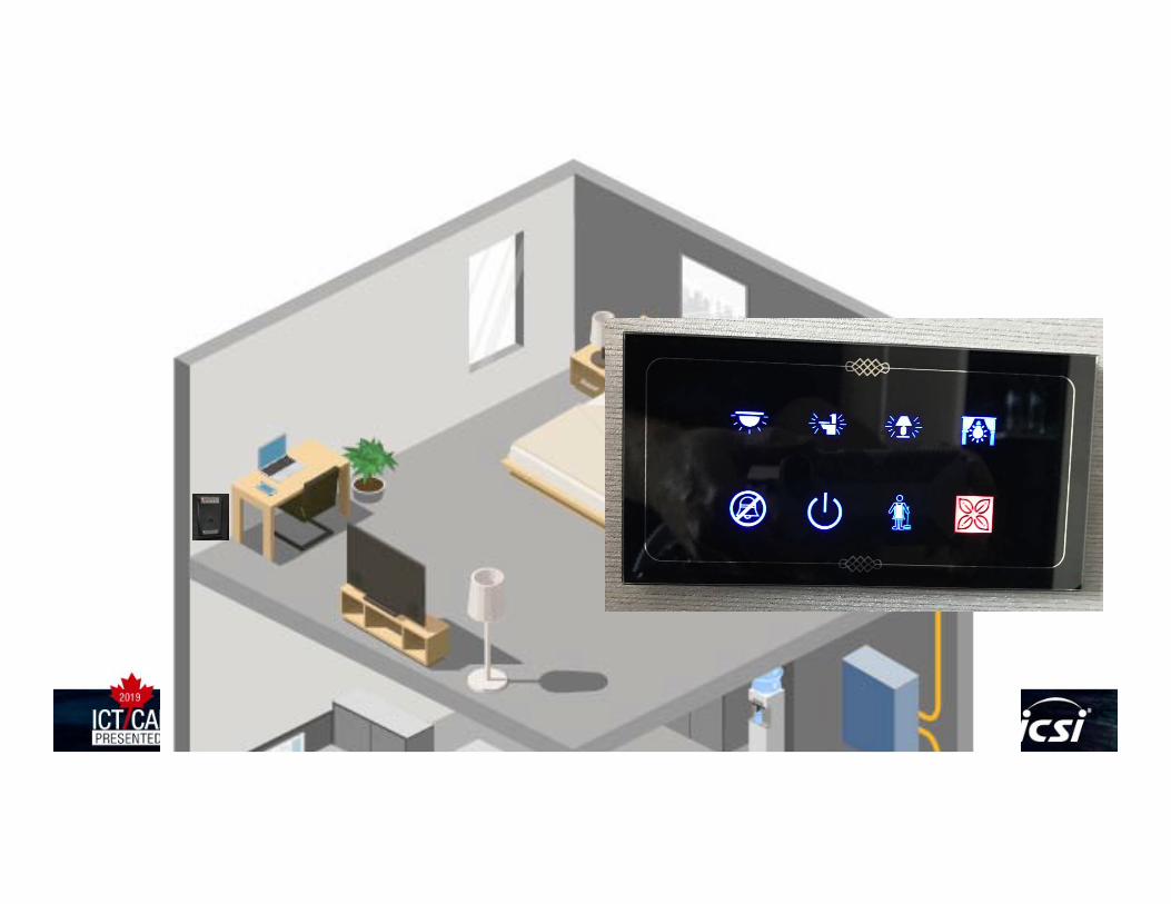
Example of PON to the desk

Example of PON to the desk• Just a single fiber
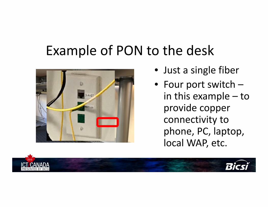
Example of PON to the desk• Just a single fiber• Four port switch –in this example – to provide copper connectivity to phone, PC, laptop, local WAP, etc.

Example of PON to the desk• Just a single fiber• Four port switch –in this example – to provide copper connectivity to phone, PC, laptop, local WAP, etc.

Troubleshooting a live network with an OTDR
• OTDR shoots a pulse of light • Measures time for light to return
– Closer events come back sooner– Farther events take longer to return
• What if there is an OLT transmitting on the fiber?– Light is always arriving– How to tell the difference from OTDR transmitted pulse and OLT
pulse– Unplug from OLT (and run)– Unused wavelength – 1625 nm or 1650 nm

Filtered test configuration for POLAN
• When troubleshooting a connectivity issue you need to be able to connect into a live system with an OTDR to troubleshoot without disturbing the system and without the POLAN signals interfering with the OTDRs measurements.
• A 1625nm Live Fiber Filter allows the OTDR to use an out of band 1625nm test wavelength to meet this purpose.
– 1625nm will not interfere with the active POLAN signals– The filter blocks the 1310nm, 1490nm and 1550nm wavelengths from
entering the OTDR port, preventing them from interfering with the measurement
1625nm Live Fiber Filter
OTDR Launch Cord
1625nm test signal
Reflected 1625nm signal
1310, 1490 & 1550 nm blocked
Desktop ONT
OLT
PatchPanel
PatchPanel
Floor Feeds Patching from ONTSplitter FeedsONT Feeds
1490nm
1550nm
1310nm
Splitter 1:n
Drop Cable to ONT
OTDR
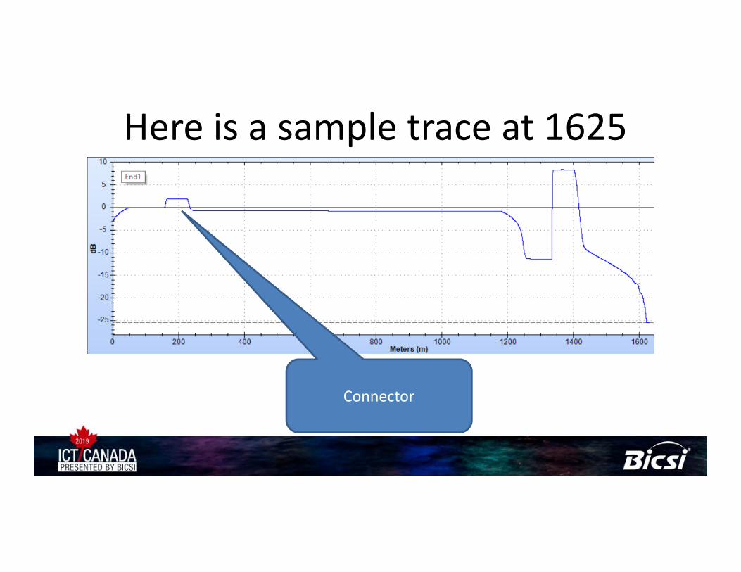
Here is a sample trace at 1625• Given the short distances in a typical PON LAN and the
large dead zone created by large pulses, you may need to use a short pulse with a very long, as long as possible, averaging time
• With only one wavelength on a live fiber, you will not be able to find a bend in the fiber
Connector

Here is a sample trace at 1625• Given the short distances in a typical PON LAN and the
large dead zone created by large pulses, you may need to use a short pulse with a very long, as long as possible, averaging time
• With only one wavelength on a live fiber, you will not be able to find a bend in the fiber
Splitter
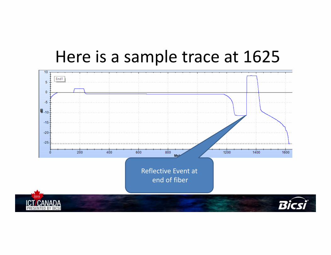
Here is a sample trace at 1625• Given the short distances in a typical PON LAN and the
large dead zone created by large pulses, you may need to use a short pulse with a very long, as long as possible, averaging time
• With only one wavelength on a live fiber, you will not be able to find a bend in the fiber
Reflective Event atend of fiber

Gotcha – don’t plug ONT to OLT with 2 meter patch cord to check if it works

Documenting Results• Request your test results in Native Format, not .pdf
– Your tester only delivers results in Paper format?• Consider using a cloud based results management service
• Check that the reference value is correct and recent• Did they verify the known good leg?• Deliver the results today, not in a month
– While your team still has access to the site

In Conclusion• PON or POL is a valid alternative to pure copper networks• Many niche markets are appearing
– Hospitals– Hotels– Government
• Follow best practices for loss testing– One Jumper reference, accurate loss budget
• OTDRs can be used for Troubleshooting– Clean the fibers before you connect them!

Jim DavisFluke Networks
[email protected] Seaway BlvdEverett, WA 98271
Amelia MannarinoImpact Technical Products
[email protected]: 416-333-5179
Thank you, Gracias, Obrigado


