JOB DATA: CHILLER MODEL NO. YK _______________ CHILLER MODEL NO. YK _____________________ NO. OF UNITS ________________________ NO. OF UNITS ______________________________ TYPE OF STARTING ___________________ TYPE OF STARTING _________________________ Included by YORK ® for Field Installation (by others) are: YES NO PER UNIT One – Two Unit Sequence Control Kit, Part No. 466-61597T □ □ _______ Condenser Water Temperature Sensor Kit, Part No. 375-01738-000 □ □ _______ Condenser Water Flow Switch □ □ _______ _______________________________________________________________ □ □ _______ _________________________________________________________ □ □ _______ Issue Date: May 1, 2017 WIRING DIAGRAMS CONTRACTOR _________________________ PURCHASER _____________________________________________ ORDER NO. ____________________________ JOB NAME ________________________________________________ JCI CONTRACT NO. _____________________ LOCATION ________________________________________________ JCI ORDER NO. _________________________ ENGINEER _______________________________________________ REFERENCE DATE ________ APPROVAL DATE ________ CONSTRUCTION DATE _______ Supersedes: 160.75-PW4 (714) Form 160.75-PW4 (517) FIELD CONTROL MODIFICATIONS FOR YK CHILLER (STYLE G)
Transcript
JOB DATA:
CHILLER MODEL NO. YK _______________ CHILLER MODEL NO. YK _____________________
NO. OF UNITS ________________________ NO. OF UNITS ______________________________
TYPE OF STARTING ___________________ TYPE OF STARTING _________________________
Included by YORK® for Field Installation (by others) are:
YES NO PER UNIT
One – Two Unit Sequence Control Kit, Part No. 466-61597T □ □ _______
Condenser Water Temperature Sensor Kit, Part No. 375-01738-000 □ □ _______
CONTRACTOR _________________________ PURCHASER _____________________________________________ ORDER NO. ____________________________ JOB NAME ________________________________________________ JCI CONTRACT NO. _____________________ LOCATION ________________________________________________ JCI ORDER NO. _________________________ ENGINEER _______________________________________________
REFERENCE DATE ________ APPROVAL DATE ________ CONSTRUCTION DATE _______
Supersedes: 160.75-PW4 (714) Form 160.75-PW4 (517)
FIELD CONTROL MODIFICATIONS FOR YK CHILLER (STYLE G)
JOHNSON CONTROLS2
FORM 160.75-PW4ISSUE DATE: 5/1/2017
This equipment is a relatively complicated apparatus. During rigging, installation, operation, maintenance, or service, individuals may be exposed to certain com-ponents or conditions including, but not limited to: heavy objects, refrigerants, materials under pressure, rotating components, and both high and low voltage. Each of these items has the potential, if misused or handled improperly, to cause bodily injury or death. It is the obligation and responsibility of rigging, instal-lation, and operating/service personnel to identify and recognize these inherent hazards, protect themselves, and proceed safely in completing their tasks. Failure to comply with any of these requirements could result in serious damage to the equipment and the property in
IMPORTANT!READ BEFORE PROCEEDING!
GENERAL SAFETY GUIDELINES
which it is situated, as well as severe personal injury or death to themselves and people at the site.
This document is intended for use by owner-authorized rigging, installation, and operating/service personnel. It is expected that these individuals possess independent training that will enable them to perform their assigned tasks properly and safely. It is essential that, prior to performing any task on this equipment, this individual shall have read and understood the on-product labels, this document and any referenced materials. This in-dividual shall also be familiar with and comply with all applicable industry and governmental standards and regulations pertaining to the task in question.
SAFETY SYMBOLSThe following symbols are used in this document to alert the reader to specific situations:
Indicates a possible hazardous situation which will result in death or serious injury if proper care is not taken.
Indicates a potentially hazardous situa‑tion which will result in possible injuries or damage to equipment if proper care is not taken.
Identifies a hazard which could lead to damage to the machine, damage to other equipment and/or environmental pollu‑tion if proper care is not taken or instruc‑tions and are not followed.
Highlights additional information useful to the technician in completing the work being performed properly.
External wiring, unless specified as an optional connection in the manufacturer’s product line, is not to be connected inside the control cabinet. Devices such as relays, switches, transducers and controls and any external wiring must not be installed inside the micro panel. All wiring must be in accor‑dance with Johnson Controls’ published specifications and must be performed only by a qualified electrician. Johnson Controls will NOT be responsible for damage/problems resulting from improper connections to the controls or application of improper control signals. Failure to follow this warn‑ing will void the manufacturer’s warranty and cause serious damage to property or personal injury.
FORM 160.75-PW4 ISSUE DATE: 5/1/2017
JOHNSON CONTROLS 3
LIST OF FIGURESFigure 1 - Remote Mode Ready To Start Con tacts ...................................................................................................7Figure 2 - Cycling Shutdown Contacts .....................................................................................................................7Figure 3 - Safety Shutdown Contacts .......................................................................................................................7Figure 4 - Run Contacts............................................................................................................................................8Figure 5 - Anticipatory/Alarm Contacts .....................................................................................................................8Figure 6 - Remote Run/Stop Contacts From Energy Management System (EMS)..................................................8Figure 7 - Remote Run/Stop Contact From Energy Management System (EMS) ...................................................9Figure 8 - Remote/Local Cycling Devices.................................................................................................................9Figure 9 - Multi-Unit Sequence .................................................................................................................................9Figure 10 - Condenser Flow Switches ....................................................................................................................10Figure 11 - Paddle Type Flow Sensor .....................................................................................................................10Figure 12 - Two Unit Sequence Control.................................................................................................................. 11Figure 13 - Multiple Units (Two) – Series Operation (Notes 8 and 11) ...................................................................12Figure 14 - Multiple Units (Two) – Parallel Operation – Individual Unit Pumps ......................................................12Figure 15 - Electro-Mechanical Starter Manual Reset Overloads (2300 to 4160 Volts)
(U.L. or C.S.A. Approved Units Only) All Chillers Except Those Equipped With “P” Compressors ......12Figure 16 - Multiple Units (Two) – Parallel Operation – Single Chilled Water Pump ..............................................13Figure 17 - Electro-Mechanical Starter Manual Reset Overloads (2300 to 4160 Volts)
(U.L. or C.S.A. Approved Units Only) Chillers Equipped With “P” Compressors .................................13Figure 18 - Remote Current Limit Setpoint With 0-10VDC Or 2-10VDC Signal .....................................................14Figure 19 - Remote Current Limit Setpoint With 0-20mA Or 4-20mA Signal ..........................................................14Figure 20 - Remote Current Limit Setpoint With PWM Signal ...............................................................................15Figure 21 - Remote Leaving Chilled Liquid Temp. Setpoint With 0-10VDC Or 2-10 VDC Signal ...........................16Figure 22 - Remote Leaving Chilled Liquid Temp. Setpoint With 0-20mA Or 4-20mA Signal .................................16Figure 23 - Remote Leaving Chilled Liquid Temperature Setpoint With PWM Signal ................................................17Figure 24 - External Signal For Refrigeration Unit Failure (Note 6) ........................................................................18Figure 25 - Run Contacts / Remote Run Light And Shutdown Indicator Plus EMS ................................................18Figure 26 - Auxiliary Safety Shutdown Input...........................................................................................................19Figure 27 - Evaporator Flow Sensors .....................................................................................................................19Figure 28 - Paddle Type Flow Sensor ....................................................................................................................19Figure 29 - Optional Heat Recovery / Head Pressure Control Output ....................................................................20Figure 30 - Optional Remote Heating Water Setpoint Offset ..................................................................................20
JOHNSON CONTROLS4
FORM 160.75-PW4ISSUE DATE: 5/1/2017
THIS PAGE INTENTIONALLY LEFT BLANK.
FORM 160.75-PW4 ISSUE DATE: 5/1/2017
JOHNSON CONTROLS 5
The chiller design allows for ease of interfacing with Energy Management Systems (EMS). The OptiView™ Control Center includes unit status contacts, provisions for remote control inputs and provisions for remote setpoint reset of leaving chilled liquid temperature and current limit for EMS interfacing (see Note 7).
Five sets of unit status contacts are factory furnished through a field wiring terminal board in the Optiview™ Control Center. Each set of contacts are single pole, normally open, rated at 5 amperes resistive at 240VAC. Chiller status contacts are provided for unit:
• Remote Mode Ready to Start – See Figure 1 on page 7.
• Cycling Shutdown – See Figure 2 on page 7.
• Safety Shutdown – See Figure 3 on page 7.
• Run (System Operating) – See Figure 4 on page 8.
• Anticipatory/Alarm – See Figure 5 on page 8.
Four sets of inputs are available to the EMS, allowing for remote control of unit operation. Input device con-tact rating shall be 5 milliamperes at 115VAC. Field wiring terminal board (TB4) in the OptiView™ Con-trol Center permits connection for the following opera-tion:
• Remote Stop Contacts – See Figure 6 on page 8.
• Remote Start Contacts – See Figure 6 on page 8.
• Remote/Local Cycling Devices – See Figure 8 on page 9.
• Multi-unit Sequence – See Figure 9 on page 9.
The chiller should not be cycled by the EMS because the large motor used to drive the cen trifugal compres-sor is limited to one start per 30 minutes. Instead, it is possible to limit the compressor motor amp draw indi-rectly or directly by the following methods:
1. Application of Sequence Control Kit, so only one unit is running, when a single unit can carry the cooling load – See Figure 12 on page 11.
2. When multiple unit installations are controlled by an EMS, remote start and stop con tacts are avail-able to start and stop each chiller per Figure 6 on page 8. Contact rating shall be 5 milliamperes at 115VAC.
3. The OptiView™ Control Center has a program-mable time clock function as a standard feature with holiday capability. This offers one preset automatic Start-Stop per day on a seven day cal-endar basis with the ability to program a single additional holiday start and stop time up to a week in advance. Chilled liquid pump control contacts (see Note 13) are also provided, allowing for ef-ficient automatic operation of the chilled waterpump to reduce energy. Two chilled liquid pump operating modes are available via the SETPOINT > SETUP screen. With the setpoint set to STAN-DARD, the chilled water pump operates for 30 seconds prior to chiller start, during chiller op-eration, coastdown, and LWT cycling shutdowns. With the setpoint set to ENHANCED, the chilled water pump operates as above plus it operates during MULTI-UNIT and REMOTE/LOCAL cy-cling shutdowns.
• Reduce the compressor-motor kW input (and thus amps), by raising the leaving chilled liquid tempera ture through remote temperature control setpoint in the “remote” operating mode. When remote tem perature reset is accomplished by sup-plying a 1 to 11 second pulse-width modulated signal, refer to Figure 20 on page 15. Through use of the remote temperature control analog in-put on the microboard, the leaving chilled liq-uid temperature may be reset via a 0 to 20 or 4 to 20mA DC current signal, or a 0 to 10 or 2 to 10VDC signal.
4. Current limiting of demand during pulldown may be accomplished by using the standard PULL-DOWN DE MAND LIMIT function provided in the OptiView™ Control Center. The “Pulldown Demand Limit” key can be programmed to limit compressor motor current from 30 to 100 percent of full load amperes, for 1 to 255 minutes follow-ing each compressor start. For more details refer to OptiView™ Control Center Instructions, Form 160.54-O1.
ENERGY MANAGEMENT SYSTEMS
JOHNSON CONTROLS6
FORM 160.75-PW4ISSUE DATE: 5/1/2017
5. Controlling the maximum allowable compres-sor motor amps from 30 to 100% through remote current limit setpoint. Refer to Figure 20 on page 15 when the remote current limit is accom-plished by supplying a 1 to 11 second pulse-width modulated signal in the “remote” oper ating mode. A jumper configurable analog input is availablefor remote current limit setpoint via a 0 to 20 or 4 to 20mA DC current signal, or a 0 to 10 or 2 to 10VDC signal.
6. A BAS System may be interfaced with the chiller OptiView™ Control Center to provide unifiedchiller plant system control. The BAS System di-rectly communicates with the OptiView™ Con-trol Center via the SC-EQ Communications card which may be installed in the Control Center. All temperatures, pressures, safety alarms and cycling information known to the OptiView™ Control Center are then available to the BAS System for integrated chiller plant control, data logging, and local and remote operator displays. The SC-EQ Communications card also allows the BAS Sys-tem to start, stop, and reset the chiller’s leav ing chilled water and current limit setpoints.
7. A BAS System may be interfaced with the chiller OptiView™ Control Center using the BAS Com-municated interface, Hardwired Analog signals or HardwiredDigitalsignalstoprovideunifiedchill-er plant system control. Mod G Chillers running software V29 (02430) or V0C for the (03630) Provided the interface for the four commandable points. The remote interface required that all four commandable points be set the same. Numerous Data Center Customers requested that this in-terface be split so that they could pick what mix they felt gave them the most reliability with their system. Version 03 software for the 03630 mi-croboard provides this capability. In the software, thereisaRemoteConfigurationscreenwhichal-lows the integrator to select how each the control parameter is interfaced.
FORM 160.75-PW4 ISSUE DATE: 5/1/2017
JOHNSON CONTROLS 7
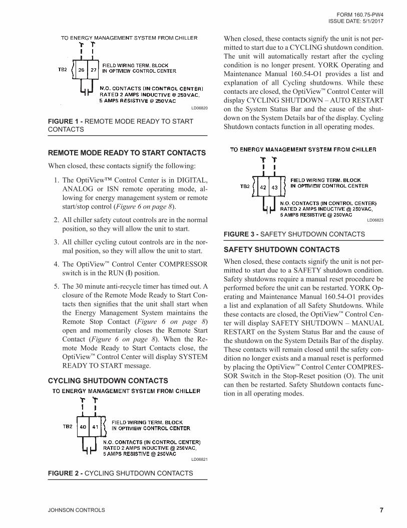
When closed, these contacts signify the unit is not per-mitted to start due to a CYCLING shutdown condition. The unit will automatically restart after the cycling condition is no longer present. YORK Operating and Maintenance Manual 160.54-O1 provides a list and explanation of all Cycling shutdowns. While these contacts are closed, the OptiView™ Control Center will display CYCLING SHUTDOWN – AUTO RESTART on the System Status Bar and the cause of the shut-down on the System Details bar of the display. Cycling Shutdown contacts function in all operating modes.
FIGURE 3 - SAFETY SHUTDOWN CONTACTS
LD06823
SAFETY SHUTDOWN CONTACTSWhen closed, these contacts signify the unit is not per-mitted to start due to a SAFETY shutdown condition. Safety shutdowns require a manual reset procedure be performed before the unit can be restarted. YORK Op-erating and Maintenance Manual 160.54-O1 provides a list and explanation of all Safety Shutdowns. While these contacts are closed, the OptiView™ Control Cen-ter will display SAFETY SHUTDOWN – MANUAL RESTART on the System Status Bar and the cause of the shutdown on the System Details Bar of the display. These contacts will remain closed until the safety con-dition no longer exists and a manual reset is performed by placing the OptiView™ Control Center COMPRES-SOR Switch in the Stop-Reset position (O). The unit can then be restarted. Safety Shutdown contacts func-tion in all operating modes.
FIGURE 1 - REMOTE MODE READY TO START CON TACTS
LD06820
REMOTE MODE READY TO START CONTACTSWhen closed, these contacts signify the following:
1. The OptiView™ Control Center is in DIGITAL, ANALOG or ISN remote op erating mode, al-lowing for energy management system or remote start/stop control (Figure 6 on page 8).
2. All chiller safety cut out controls are in the normal position, so they will allow the unit to start.
3. All chiller cycling cutout controls are in the nor-mal position, so they will allow the unit to start.
4. The OptiView™ Control Center COMPRESSOR switch is in the RUN (l) position.
5. The 30 minute anti-recycle timer has timed out. A closure of the Remote Mode Ready to Start Con-tacts then signifies that theunit shall startwhenthe Energy Management System maintains the Remote Stop Contact (Figure 6 on page 8) open and momentarily closes the Remote Start Con tact (Figure 6 on page 8). When the Re-mote Mode Ready to Start Con tacts close, the OptiView™ Control Center will display SYSTEM READY TO START message.
CYCLING SHUTDOWN CONTACTS
FIGURE 2 - CYCLING SHUTDOWN CONTACTS
LD06821
JOHNSON CONTROLS8
FORM 160.75-PW4ISSUE DATE: 5/1/2017
LD06822
FIGURE 4 - RUN CONTACTS
RUN CONTACTS When closed, these contacts signify that the unit is op-erating. The OptiView™ Control Center will display a System Run Message.
FIGURE 5 - ANTICIPATORY/ALARM CONTACTS
LD04604
ANTICIPATORY/ALARM CONTACTSThese contacts will close whenever one or more of the following WARNING conditions occurs. They will re-main closed as long as the condition is in effect. On most warnings, the contacts automatically open when the condition is no longer present. On those warnings marked with an asterisk, the contacts will open only after the condition is no longer present and the WARN-ING RESET key is pressed in Operator (or higher) ac-cess level.
Real time clock failure, Condenser or Evaporator Transducer Error*, Refrigerant lLevel Out of Range, Standby Lube – Low Oil Pressure*, Setpoint Over-ride*, Condenser-High Pressure Limit, Evaporator-Low Pressure Limit, Vanes Uncalibrated – Fixed speed, Harmonic Filter – Operation Inhibited, Harmonic Fil-ter – Data Loss, Harmonic Filter – Input Frequency Out of Range.
FIGURE 6 - REMOTE RUN/STOP CONTACTS FROM ENERGY MANAGEMENT SYSTEM (EMS)
LD06824
REMOTE RUN/STOP CONTACTS FROM ENERGY MANAGEMENT SYSTEM
Earlier YK Mod G Chillers used the 1-7-8 terminals to remotely Run/Stop the chiller with a hardwired in-terface. When the OptiView™ Control Center is in the DIGITAL or ANALOG remote operating mode and the COMPRESSOR switch is in the RUN (l) position, with the Remote Stop Contacts open, and the Remote Mode Ready to Run Contacts closed (Figure 1 on page 7), the unit will start via a closure of the Remote Run Contacts. A subsequent closure of the Energy Management System Remote Stop Contacts causes the chiller to shut down. The OptiView™ Control Center will display REMOTE STOP because the Energy Man-agement System Remote Stop Contact has commanded the unit to shutdown.
It is recommended that maintained contacts be used for both RUN and STOP.
Even when the chiller is applied with Re‑mote Run‑Stop (when the Control Center is in the “remote” oper ating mode), an EMERGENCY STOP by an operator or others can STOP the compressor from the OptiView™ Control Center and prevent the chiller from restarting. However, the operator cannot locally start the com‑pressor using “compressor” start switch, when the control center is in the “remote” operating mode.
FORM 160.75-PW4 ISSUE DATE: 5/1/2017
JOHNSON CONTROLS 9
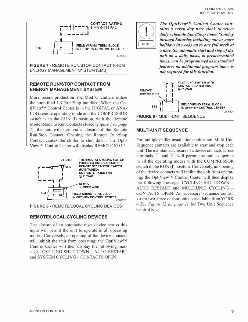
FIGURE 7 - REMOTE RUN/STOP CONTACT FROM ENERGY MANAGEMENT SYSTEM (EMS)
LD22319
REMOTE RUN/STOP CONTACT FROM ENERGY MANAGEMENT SYSTEMMore recent production YK Mod G chillers utilize the simplified 1-7 Run/Stop interface. When the Op-tiView™ Control Center is in the DIGITAL or ANA-LOG remote operating mode and the COMPRESSOR switch is in the RUN (l) position, with the Remote Mode Ready to Run Contacts closed (Figure 1 on page 7), the unit will start via a closure of the Remote Run/Stop Contact. Opening the Remote Run/Stop Contact causes the chiller to shut down. The Opti- View™ Control Center will display REMOTE STOP.
LD06825
FIGURE 8 - REMOTE/LOCAL CYCLING DEVICES
REMOTE/LOCAL CYCLING DEVICES The closure of an automatic reset device across this input will permit the unit to operate in all operating modes. Conversely, an opening of the device contacts will inhibit the unit from operating; the OptiView™ Control Center will then display the following mes-sages: CYCLING SHUTDOWN – AUTO RESTART and SYSTEM CYCLING – CONTACTS OPEN.
The OptiView™ Control Center con‑tains a seven day time clock to select daily schedule Start/Stop times (Sunday through Saturday including one or more holidays in week) up to one full week at a time. So automatic start and stop of the unit on a daily basis, at pre determined times, can be programmed as a standard feature; an additional program timer is not required for this function.
LD06828
FIGURE 9 - MULTI-UNIT SEQUENCE
MULTI-UNIT SEQUENCE
For multiple chiller installation application, Multi-Unit Sequence contacts are available to start and stop each unit. The main tained closure of a device contacts across terminals 1 and 9 will permit the unit to operate in all the operating modes with the COMPRESSOR switch in the RUN (l) position. Conversely, an opening of the device con tacts will inhibit the unit from operat-ing; the OptiView™ Control Center will then display the fol lowing message: CYCLING SHUTDOWN – AUTO RESTART and MULTIUNIT CYCLING – CONTACTS OPEN. An accessory sequence control kit for two, three or four units is available from YORK – See Figure 12 on page 11 for Two Unit Sequence Control Kit.
JOHNSON CONTROLS10
FORM 160.75-PW4ISSUE DATE: 5/1/2017
J14-
MICROBOARD
CONDENSERFLOW SWITCH
CONDENSERFLOW SWITCH
THERMAL-TYPE FLOW SENSOR
11
1
8
7
TB4
I/O BOARDPADDLE-TYPE FLOW SENSOR
J14-
MICROBOARD
CONDENSERFLOW SWITCH
CONDENSERFLOW SWITCH
THERMAL-TYPE FLOW SENSOR
11
1
8
7
TB4
I/O BOARDPADDLE-TYPE FLOW SENSOR
MIC
RO
BO
AR
D
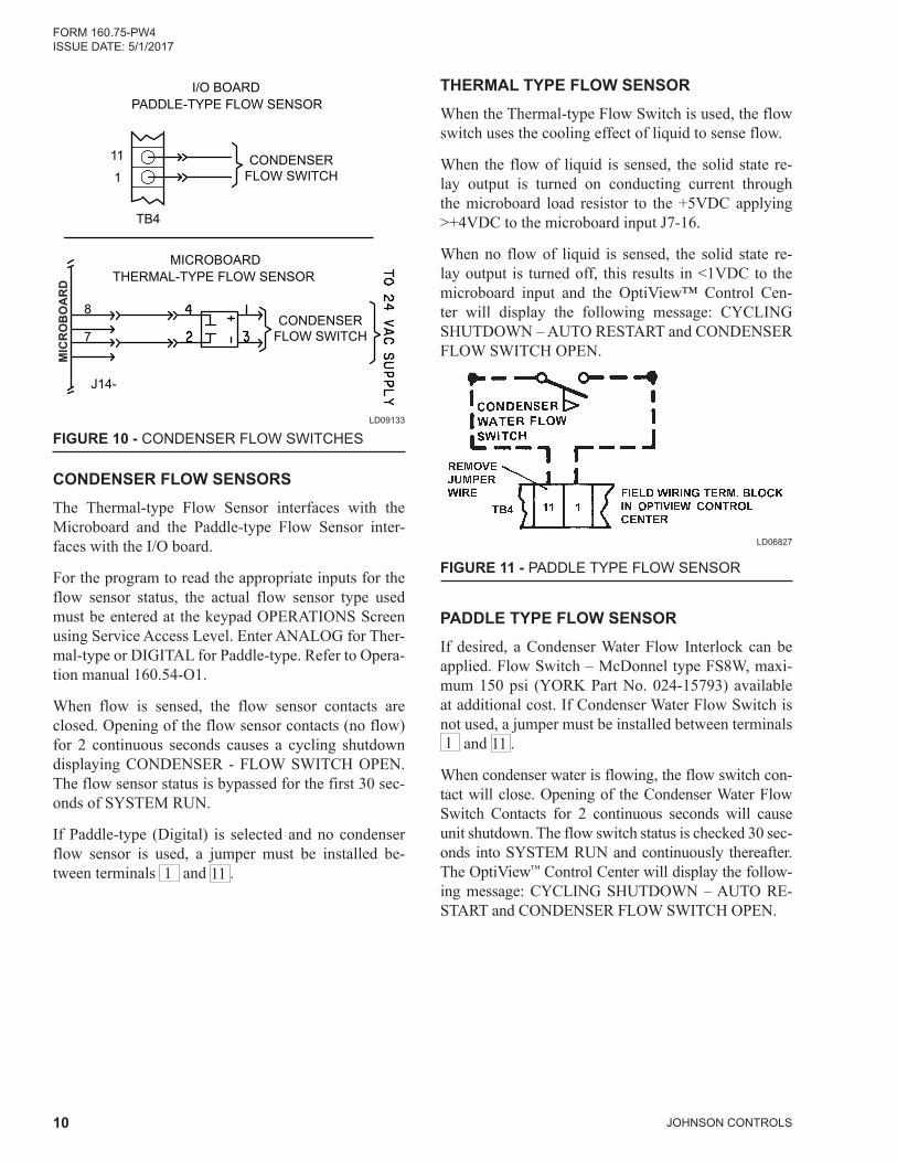
FIGURE 10 - CONDENSER FLOW SWITCHESLD09133
CONDENSER FLOW SENSORSThe Thermal-type Flow Sensor interfaces with the Microboard and the Paddle-type Flow Sensor inter-faces with the I/O board.
For the program to read the appropriate inputs for the flow sensor status, the actual flow sensor type used must be entered at the keypad OPERATIONS Screen using Service Access Level. Enter ANALOG for Ther-mal-type or DIGITAL for Paddle-type. Refer to Opera-tion manual 160.54-O1.
When flow is sensed, the flow sensor contacts are closed. Opening of the flow sensor contacts (no flow) for 2 continuous seconds causes a cycling shutdown displaying CONDENSER - FLOW SWITCH OPEN. The flow sensor status is bypassed for the first 30 sec-onds of SYSTEM RUN.
If Paddle-type (Digital) is selected and no condenser flow sensor is used, a jumper must be installed be-tween terminals 1 and 11 .
THERMAL TYPE FLOW SENSORWhen the Thermal-type Flow Switch is used, the flow switch uses the cooling effect of liquid to sense flow.
When the flow of liquid is sensed, the solid state re-lay output is turned on conducting current through the microboard load resistor to the +5VDC applying >+4VDC to the microboard input J7-16.
When no flow of liquid is sensed, the solid state re-lay output is turned off, this results in <1VDC to the microboard input and the OptiView™ Control Cen-ter will display the following message: CYCLING SHUTDOWN – AUTO RESTART and CONDENSER FLOW SWITCH OPEN.
FIGURE 11 - PADDLE TYPE FLOW SENSOR
LD06827
PADDLE TYPE FLOW SENSORIf desired, a Condenser Water Flow Interlock can be applied. Flow Switch – McDonnel type FS8W, maxi-mum 150 psi (YORK Part No. 024-15793) available at additional cost. If Condenser Water Flow Switch is not used, a jumper must be installed between terminals 1 and 11 .
When condenser water is flowing, the flow switch con-tact will close. Opening of the Condenser Water Flow Switch Contacts for 2 continuous seconds will cause unit shutdown. The flow switch status is checked 30 sec-onds into SYSTEM RUN and continuously thereafter. The OptiView™ Control Center will display the follow-ing message: CYCLING SHUTDOWN – AUTO RE-START and CONDENSER FLOW SWITCH OPEN.
FORM 160.75-PW4 ISSUE DATE: 5/1/2017
JOHNSON CONTROLS 11
LD06835
FIGURE 12 - TWO UNIT SEQUENCE CONTROL
RWT has 20°F(-6.7° to 80°F(26.7°C) range with ad-justable differential of 3-1/2 to 14°F (1.9 to 7.8°C); 6 ft. of capillary with 3/8" x 5" bulb and 1/2" NPT brass well (maximum liquid DWP 300 psig). The thermostat is drawn to indicate its operation closes on rise. A 1/2" pipe coupling in the return chilled water line from the building must be furnished (by others) for RWT con-trol well.
TWO UNIT SEQUENCE CONTROLProvides that cycling thermostat RWT will automati-cally cycle either #1 or #2 unit. Timer 3TR is an addi-tional feature which prevents simultaneous starting of lead and lag unit following a power failure and elimi-nates nuisance starting of lag unit due to periodic fluc-tuations in temperature. For two unit sequence control kit, order York Accessory Kit No. 466-61597T for con-trols as specified with NEMA 1 enclosure.
JOHNSON CONTROLS12
FORM 160.75-PW4ISSUE DATE: 5/1/2017
LD06826
FIGURE 13 - MULTIPLE UNITS (TWO) – SERIES OPERATION (NOTES 8 AND 11)
EVAPORATOR EVAPORATOR
MULTIPLE UNITS (TWO) – PARALLEL OPERATION – INDIVIDUAL UNIT PUMPSThis piping arrangement is the same as Figure 16 on page 13, except that the chilled water pumps associ-ated with each evaporator are cycled ON and OFF with the unit. This results in reduced chilled water flow rates whenever a single unit can handle the cooling load. Be-cause no chilled water flows through the inoperative unit, the mixed water temperature peculiar to using a single pump is avoided. When one unit is cut-out by the sequence control (Figure 12 on page 11) the tem-perature of the supply chilled water does not change.
FIGURE 15 - ELECTRO-MECHANICAL STARTER MANUAL RESET OVERLOADS (2300 TO 4160 VOLTS) (U.L. OR C.S.A. APPROVED UNITS ONLY) ALL CHILLERS EXCEPT THOSE EQUIPPED WITH “P” COMPRESSORS
LD06831
MULTIPLE UNITS (TWO) - SERIES OPERATIONThe supply chilled water temperature to the building is normally determined by the CHILLED LIQUID TEM-PERATURE setpoint for Unit #2. When lead selector position of sequence control kit (Figure 12 on page 11) is Unit #1, the supply chilled water temperature to the building will be the temperature control setpoint on Unit #1 OptiView™ Control Center. If lower tem-perature is desired, reprogram the CHILLED LIQUID TEMPERATURE setpoint for Unit #1.
FIGURE 14 - MULTIPLE UNITS (TWO) – PARALLEL OPERATION – INDIVIDUAL UNIT PUMPS
LD06829
FORM 160.75-PW4 ISSUE DATE: 5/1/2017
JOHNSON CONTROLS 13
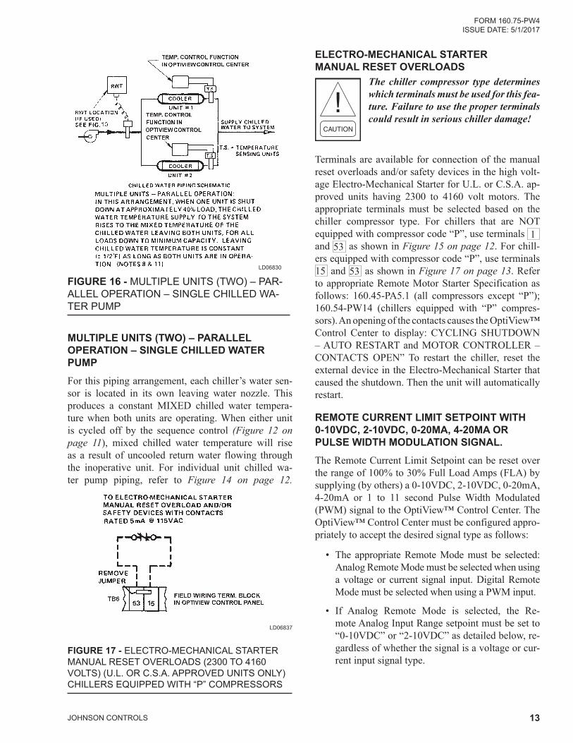
ELECTRO-MECHANICAL STARTER MANUAL RESET OVERLOADS
The chiller compressor type determines which terminals must be used for this fea‑ture. Failure to use the proper terminals could result in serious chiller damage!
Terminals are available for connec tion of the manual reset overloads and/or safety devices in the high volt-age Electro-Mechanical Starter for U.L. or C.S.A. ap-proved units having 2300 to 4160 volt motors. The appropriate terminals must be selected based on the chiller compressor type. For chillers that are NOT equipped with compressor code “P”, use terminals 1 and 53 as shown in Figure 15 on page 12. For chill-ers equipped with compressor code “P”, use terminals 15 and 53 as shown in Figure 17 on page 13. Refer to appropriate Remote Motor Starter Specification as follows: 160.45-PA5.1 (all compressors except “P”); 160.54-PW14 (chillers equipped with “P” compres-sors). An opening of the contacts causes the OptiView™ Control Center to display: CYCLING SHUTDOWN – AUTO RESTART and MOTOR CON TROLLER – CONTACTS OPEN” To restart the chiller, reset the external device in the Electro-Mechanical Starter that caused the shutdown. Then the unit will automatically restart.
REMOTE CURRENT LIMIT SETPOINT WITH 0-10VDC, 2-10VDC, 0-20MA, 4-20MA OR PULSE WIDTH MODULATION SIGNAL.The Remote Current Limit Setpoint can be reset over the range of 100% to 30% Full Load Amps (FLA) by supplying (by others) a 0-10VDC, 2-10VDC, 0-20mA, 4-20mA or 1 to 11 second Pulse Width Modulated (PWM) signal to the OptiView™ Control Center. The OptiView™ Control Center must be configured appro-priately to accept the desired signal type as follows:
• The appropriate Remote Mode must be selected: Analog Remote Mode must be selected when using a voltage or current signal input. Digital Remote Mode must be selected when using a PWM input.
• If Analog Remote Mode is selected, the Re-mote Analog Input Range setpoint must be set to “0-10VDC” or “2-10VDC” as detailed below, re-gardless of whether the signal is a voltage or cur-rent input signal type.
LD06830
FIGURE 16 - MULTIPLE UNITS (TWO) – PAR-ALLEL OPERATION – SINGLE CHILLED WA-TER PUMP
MULTIPLE UNITS (TWO) – PARALLEL OPERATION – SINGLE CHILLED WATER PUMPFor this piping arrangement, each chiller’s water sen-sor is located in its own leaving water nozzle. This produces a constant MIXED chilled water tempera-ture when both units are operating. When either unit is cycled off by the sequence control (Figure 12 on page 11), mixed chilled water tempera ture will rise as a result of uncooled return water flowing through the inoperative unit. For individual unit chilled wa-ter pump piping, refer to Figure 14 on page 12.
LD06837
FIGURE 17 - ELECTRO-MECHANICAL STARTER MANUAL RESET OVERLOADS (2300 TO 4160 VOLTS) (U.L. OR C.S.A. APPROVED UNITS ONLY) CHILLERS EQUIPPED WITH “P” COMPRESSORS
JOHNSON CONTROLS14
FORM 160.75-PW4ISSUE DATE: 5/1/2017
• Microboard Program Jumper P23 must be posi-tioned appropriately per the input signal type as detailedbelow.ItisrecommendedthataqualifiedService Technician position this jumper.
Important! The signal type used for Re‑mote Current Limit Setpoint reset and the signal type used for Remote Leaving Chilled Liquid Temperature setpoint re‑set must be the same. For example, if a 0‑10VDC signal is being used for Remote Leaving Chilled Liquid Temperature Re‑set , then a 0‑10VDC signal must be used for Remote Current Limit Reset.
FIGURE 18 - REMOTE CURRENT LIMIT SETPOINT WITH 0-10VDC OR 2-10VDC SIGNAL
SIGNAL
COMMON 5
1+
J22
LD04498
0-10VDC - As shown in Figure 18 on page 14, connect input to Microboard J22-1 (signal) and J22-5 (Gnd). The setpoint varies linearly from 100% to 30% FLA as the input varies from 0-10VDC. This input will only be accepted when Analog Remote Mode is select-ed, the REMOTE ANALOG INPUT RANGE setpoint is set for 0-10 volts, and Microboard Program Jumper JP23 has been removed. Calculate the setpoint for vari-ous inputs as follows:
SETPOINT (%) = 100 – (VDC X 7)
For example, if the input is 5VDC, the setpoint would be set to 65% as follows:
SETPOINT (%) = 100 – (5 X 7) = 100 – 35 = 65%
2-10VDC - As shown in Figure 18 on page 14, connect input to Microboard J22-1 (signal) and J22-5 (Gnd). The setpoint varies linearly from 100% to 30% FLA as the input varies from 2 to 10VDC. This input will only be accepted when ANALOG Remote Mode is selected, the REMOTE ANALOG INPUT RANGE setpoint is set for “2-10 Volts” and Microboard Pro-gram Jumper JP23 has been removed. Calculate the setpoint for various inputs as follows:
SETPOINT (%) = 100 – [(VDC – 2) x 8.75]
For example, if the input is 5VDC, the setpoint would be set to 74% as follows:
Setpoint (%) = 100 – [(5-2) x 8.75]
= 100 – [3 x 8.75]
= 100 – 26.25 = 74%
LD04499
FIGURE 19 - REMOTE CURRENT LIMIT SETPOINT WITH 0-20mA OR 4-20mA SIGNAL
SIGNAL
COMMON 5
2+
J22
0-20 mA - As shown in Figure 19 on page 14, con-nect input to Microboard J22-2 (signal) and J22-5 (Gnd). The setpoint varies linearly from 100% to 30% FLA as the input varies from 0-20mA. This input will only be accepted when ANALOG Remote Mode is selected, the REMOTE ANALOG INPUT RANGE setpoint is set for 0-10 Volts, and Microboard Program Jumper JP23 has been placed on pins 1 and 2. Calcu-late the setpoint for various inputs as follows:
SETPOINT (%) = 100 – (ma x 3.5)
For example, if the input is 8mA, the setpoint would be set to 72% as follows:
SETPOINT (%) = 100 – (8 x 3.5) = 100 – 28 = 72%
4-20mA - As shown in Figure 19 on page 14, connect input to Microboard J22-2 (signal) and J22-5 (Gnd). The setpoint varies linearly from 100% to 30% FLA as the input varies from 4-20mA. This input will only be accepted when ANALOG Remote Mode is selected, the REMOTE ANALOG INPUT RANGE setpoint is set for “2-10 Volts” and Microboard Program Jumper JP23 has been placed on pins 1 and 2. Calculate the setpoint for various inputs as follows:
SETPOINT (%) = 100 – [(mA – 4) x 4.375]
For example, if the input is 8mA, the setpoint would be set to 83% as follows:
FIGURE 20 - REMOTE CURRENT LIMIT SETPOINT WITH PWM SIGNAL
LD06832
PWM - The Pulse Width Modulation input is in the form of a 1 to 11 second relay contact closure that ap-plies 115VAC to the I/O Board TB4-20 for 1 to 11 sec-onds. As shown in Figure 20 on page 15, connect dry closure relay contacts between I/O Board TB4-20 (signal) and TB4-1 (115VAC). The setpoint varies lin-early from 100% to 30% as the relay contact closure time changes from 1 to 11 seconds. The relay contacts should close for 1 to 11 seconds at least once every 30 minutes to maintain the setpoint to the desired value. If a 1 to 11 second closure is not received within 30 minutes of the last closure, the setpoint is defaulted to 100%. A closure is only accepted at rates not to exceed once every 70 seconds. This input will only be accept-ed in DIGITAL Remote Mode. Calculate the setpoint for various pulse widths as follows:
SETPOINT (%) = 100 – [(PULSE WIDTH IN SECONDS – 1) X 7]
For example, if the relay contacts close for 3 seconds, the setpoint would be set to 86% as follows:
REMOTE LEAVING CHILLED LIQUID SETPOINT WITH 0-10VDC, 2-10VDC, 0-20MA, 4-20MA OR PULSE WIDTH MODULATION SIGNALRemote Leaving Chilled Liquid Temperature Setpoint Reset can be accomplished by supplying (by others) a 0-10VDC, 2-10VDC, 0-20mA, 4-20mA or 1 to 11 second Pulse Width Modulated (PWM) signal to the Control Center. The LEAVING CHILLED LIQUID TEMPERATURE SETPOINT is programmable over the range of 38°F(3.3°C) to 70°F(21.1°C) (water ap-
plications), 36°F(2.2°C) to 70°F(21.1°C) (water ap-plications with Smart Freeze Protection enabled) or 10°F(-12.2°C) to 70°F(21.1°C) (brine applications). The Remote Input Signal changes the setpoint by cre-ating an offset above the locally programmed Leav-ing Chilled Liquid Temperature Base Setpoint value. The setpoint can be remotely changed over the range of 10°(5.6°C) or 20ºF(11.1°C) (as per the locally programmed REMOTE RESET TEMPERATURE RANGE setpoint) above the Local Leaving Chilled Liquid Temperature Setpoint. For example, if the Lo-cal Setpoint is 40°F (4.4°C) and the REMOTE RESET TEMPERATURE RANGE setpoint is programmed for 10°F(5.6°C), the Leaving Chilled Liquid Tempera-ture setpoint can be remotely reset over the range of 40°F(4.4°C) to 50°F(10°C). The Control Center must be configured appropriately to accept the desired sig-nal type as follows:
• The appropriate Remote Mode must be selected: ANALOG REMOTE MODE must be selected when using a voltage or current signal input. DIG-ITAL REMOTE MODE must be selected when using a PWM input.
• If ANALOG REMOTE MODE is selected, the REMOTE ANALOG INPUT RANGE setpoint must be set to “0-10VDC” or “2-10VDC” as de-tailed below, regardless of whether the signal is a voltage or current signal type.
• Microboard Program Jumper JP24 must be posi-tioned appropriately per the input signal type as detailedbelow.ItisrecommendedaqualifiedSer-vice Technician position this jumper.
Important! The signal type used for Re‑mote Leaving Chilled Liquid Temperature Setpoint Reset and the signal type used for Remote Current Limit Setpoint Reset must be the same. For example, if a 0‑10VDC signal is being used for Remote Current Limit Setpoint, then a 0‑10VDC signal must be used for Leaving Chilled Liquid Temperature Reset.
JOHNSON CONTROLS16
FORM 160.75-PW4ISSUE DATE: 5/1/2017
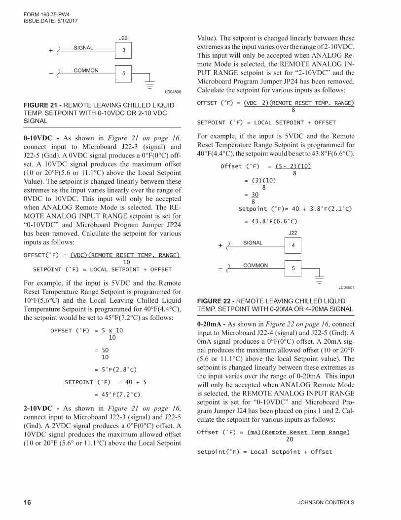
Value). The setpoint is changed linearly between these extremes as the input varies over the range of 2-10VDC. This input will only be accepted when ANALOG Re-mote Mode is selected, the REMOTE ANALOG IN-PUT RANGE setpoint is set for “2-10VDC” and the Microboard Program Jumper JP24 has been removed. Calculate the setpoint for various inputs as follows:
For example, if the input is 5VDC and the Remote Reset Temperature Range Setpoint is programmed for 40°F(4.4°C), the setpoint would be set to 43.8°F(6.6°C).
FIGURE 22 - REMOTE LEAVING CHILLED LIQUID TEMP. SETPOINT WITH 0-20MA OR 4-20MA SIGNAL
LD04501
0-20mA - As shown in Figure 22 on page 16, connect input to Microboard J22-4 (signal) and J22-5 (Gnd). A 0mA signal produces a 0°F(0°C) offset. A 20mA sig-nal produces the maximum allowed offset (10 or 20°F (5.6 or 11.1°C) above the local Setpoint value). The setpoint is changed linearly between these extremes as the input varies over the range of 0-20mA. This input will only be accepted when ANALOG Remote Mode is selected, the REMOTE ANALOG INPUT RANGE setpoint is set for “0-10VDC” and Microboard Pro-gram Jumper J24 has been placed on pins 1 and 2. Cal-culate the setpoint for various inputs as follows:
Offset (°F) = (mA)(Remote Reset Temp Range) 20
Setpoint(°F) = Local Setpoint + Offset
SIGNAL
COMMON 5
3+
J22
FIGURE 21 - REMOTE LEAVING CHILLED LIQUID TEMP. SETPOINT WITH 0-10VDC OR 2-10 VDC SIGNAL
LD04500
0-10VDC - As shown in Figure 21 on page 16, connect input to Microboard J22-3 (signal) and J22-5 (Gnd). A 0VDC signal produces a 0°F(0°C) off-set. A 10VDC signal produces the maximum offset (10 or 20°F(5.6 or 11.1°C) above the Local Setpoint Value). The setpoint is changed linearly between these extremes as the input varies linearly over the range of 0VDC to 10VDC. This input will only be accepted when ANALOG Remote Mode is selected. The RE-MOTE ANALOG INPUT RANGE setpoint is set for “0-10VDC” and Microboard Program Jumper JP24 has been removed. Calculate the setpoint for various inputs as follows:
OFFSET(°F) = (VDC)(REMOTE RESET TEMP. RANGE) 10
SETPOINT (°F) = LOCAL SETPOINT + OFFSET
For example, if the input is 5VDC and the Remote Reset Temperature Range Setpoint is programmed for 10°F(5.6°C) and the Local Leaving Chilled Liquid Temperature Setpoint is programmed for 40°F(4.4°C), the setpoint would be set to 45°F(7.2°C) as follows:
OFFSET (°F) = 5 x 10 10
= 50 10
= 5°F(2.8°C)
SETPOINT (°F) = 40 + 5
= 45°F(7.2°C)
2-10VDC - As shown in Figure 21 on page 16, connect input to Microboard J22-3 (signal) and J22-5 (Gnd). A 2VDC signal produces a 0°F(0°C) offset. A 10VDC signal produces the maximum allowed offset (10 or 20°F (5.6° or 11.1°C) above the Local Setpoint
FORM 160.75-PW4 ISSUE DATE: 5/1/2017
JOHNSON CONTROLS 17
LD06833
FIGURE 23 - REMOTE LEAVING CHILLED LIQUID TEMPERATURE SETPOINT WITH PWM SIGNAL
PWM – The Pulse Width Modulation input is in the form of a 1 to 11 second relay contact closure that ap-plies 115VAC to the I/O Board TB4-19 for 1-11 sec-onds. As shown in Figure 23 on page 17, connect dry closure relay contacts between I/O Board TB4-19 (input) and TB4-1 (115VAC). A contact closure time (pulse width) of 1 second produces a 0°F(0°C) offset. An 11 second closure produces the maximum allowed offset (10 or 20°F(5.6° or 11.1°C) above the local setpoint value). The relay contacts should close for 1 to 11 seconds at least once every 30 minutes to maintain the setpoint to the desired value. If a 1 to 11 second closure is not received within 30 minutes of the last closure, the setpoint is defaulted to the Local setpoint value. A closure is only accepted at rates not to exceed once every 70 seconds. This input will only be accept-ed in DIGITAL Remote Mode. Calculate the setpoint for various pulse widths as follows:
OFFSET(°F) =
(PULSE WIDTH IN SECONDS)(REMOTE RESET TEMP. RANGE)
10
SETPOINT(°F) = LOCAL SETPOINT + OFFSET
For example, if the relay contacts close for 5 seconds and the Remote Reset Temperature Range setpoint is programmed for 10°F(5.6°C), and the Local Leaving Chilled Liquid Temperature setpoint is programmed for 40°F(4.4°C), the setpoint would be set to 44°F(6.7°C) as follows: Offset (°F) = (5 – 1)(10) 10
= (4)(10) 10
= 40 10
= 4°F(2.2°C)
Setpoint (°F) = 40 + 4
= 44°F(6.7°C)
For example, if the input is 8mA, the Remote Re-set Temperature Range Setpoint is programmed for 10°F(5.6°C) and the Local Leaving Chilled Liquid Temperature Setpoint is programmed for 40°F(4.4°C), the setpoint would be set to 44°F(6.7°C) as follows:
Offset (°F) = (8)(10) 20
= (80) 20
= 4°F(2.2°C)
Setpoint (°F) = 40 + 4
= 44°F(6.7°C)
4-20mA - As shown in Figure 22 on page 16, con-nect input to MicroBoard J22-4 (signal) and J22-5 (Gnd.). A 4mA signal produces a 0°F (0°C) offset. A 20mA signal produces the maximum allowed off-set (10 or 20°F(5.6° or 11.1°C) above the Local Setpoint value). The setpoint is changed linearly be-tween these extremes as the input varies over the range of 0-20mA. This input will only be accepted when ANALOG Remote Mode is selected, the REMOTE ANALOG INPUT RANGE setpoint is set for “2-10VDC” and Microboard Program Jumper JP24 has been placed on pins 1 and 2. Calculate the setpoint for various inputs as follows:
Offset(°F) = (ma – 4)(Remote Temp. reset range) 16
Setpoint(°F) = Local Setpoint + Offset
For example, if input is 8mA, and the Remote Re-set Temperature Range setpoint is programmed for 10°F(5.6°C) and the Local Leaving Chilled Liquid Temperature setpoint is programmed for 40°F(4.4°C), the setpoint would be set to 42.5°F(5.8°C) as follows:
Offset (°F) = (8 – 4)(10) 16
= (4)(10) 16
= 40 16
= 2.5°F(1.4°C)
Setpoint (°F) = 40 + 2.5
= 42.5°F(5.8°C)
JOHNSON CONTROLS18
FORM 160.75-PW4ISSUE DATE: 5/1/2017
LD06834
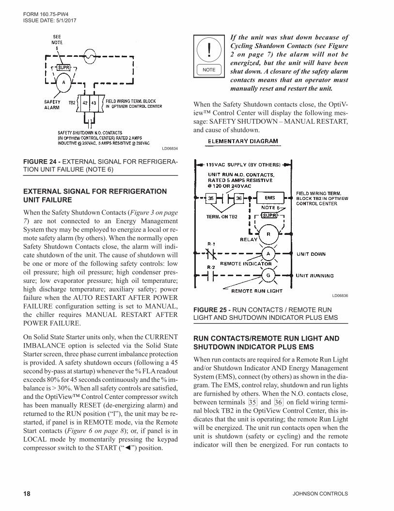
FIGURE 24 - EXTERNAL SIGNAL FOR REFRIGERA-TION UNIT FAILURE (NOTE 6)
EXTERNAL SIGNAL FOR REFRIGERATION UNIT FAILUREWhen the Safety Shutdown Contacts (Figure 3 on page 7) are not connected to an Energy Management System they may be employed to energize a local or re-mote safety alarm (by others). When the normally open Safety Shutdown Contacts close, the alarm will indi-cate shutdown of the unit. The cause of shutdown will be one or more of the following safety controls: low oil pressure; high oil pressure; high condenser pres-sure; low evaporator pressure; high oil temperature; high discharge temperature; auxiliary safety; power failure when the AUTO RESTART AFTER POWER FAILURE configuration setting is set to MANUAL, the chiller requires MANUAL RE START AFTER POWER FAILURE.
On Solid State Starter units only, when the CURRENT IMBALANCE option is selected via the Solid State Starter screen, three phase current imbalance protection is provided. A safety shutdown occurs (following a 45 second by-pass at startup) whenever the % FLA readout exceeds 80% for 45 seconds continuously and the % im-balance is > 30%. When all safety controls are satisfied, and the OptiView™ Control Center compressor switch has been manually RESET (de-energizing alarm) and returned to the RUN position (“l”), the unit may be re-started, if panel is in REMOTE mode, via the Remote Start contacts (Figure 6 on page 8); or, if panel is in LOCAL mode by momentarily pressing the keypad compressorswitchtotheSTART(“◄”)position.
If the unit was shut down because of Cycling Shutdown Contacts (see Figure 2 on page 7) the alarm will not be energized, but the unit will have been shut down. A closure of the safety alarm contacts means that an operator must manually reset and restart the unit.
When the Safety Shutdown contacts close, the OptiV-iew™ Control Center will display the following mes-sage: SAFETY SHUTDOWN – MANUAL RESTART, and cause of shutdown.
LD06836
FIGURE 25 - RUN CONTACTS / REMOTE RUN LIGHT AND SHUTDOWN INDICATOR PLUS EMS
RUN CONTACTS/REMOTE RUN LIGHT AND SHUTDOWN INDICATOR PLUS EMSWhen run contacts are required for a Remote Run Light and/or Shut down Indicator AND Energy Management System (EMS), connect (by others) as shown in the dia-gram. The EMS, control relay, shutdown and run lights are furnished by others. When the N.O. contacts close, between terminals 35 and 36 on field wiring termi-nal block TB2 in the OptiView Control Center, this in-dicates that the unit is operating; the remote Run Light will be energized. The unit run contacts open when the unit is shutdown (safety or cycling) and the remote indica tor will then be energized. For run contacts to
FORM 160.75-PW4 ISSUE DATE: 5/1/2017
JOHNSON CONTROLS 19
EMS only refer to Figure 4 on page 8. When ter-minals 35 and 36 are not used for an EMS, they may be connected to a remote Run Light. The control relay scheme shown in Figure 25 on page 18 can also be applied for a remote Run Light AND a Remote Shut-down Indicator, when an EMS is not used.
LD06838
FIGURE 26 - AUXILIARY SAFETY SHUTDOWN INPUT
The closure of a Momentary or Maintained N.O. Switch or Relay Contacts will cause the unit to shut-down and display: SAFETY SHUTDOWN – MAN-UAL RESTART and AUXILIARY SAFETY – CON-TACTS CLOSED. The unit will not restart until the contacts open and the keypad COM PRESSOR switch is moved to the STOP-RESET position (“O”) and then to the START (“”)position.
MIC
RO
BO
AR
D
J14-
MICROBOARDTHERMAL-TYPE FLOW SENSOR
12
1
TB4
I/O BOARDPADDLE-TYPE FLOW SENSOR
EVAPORATORFLOW SWITCH
CHILLED WATERFLOW SWITCH
5 4
2
1
34
TO 24VA
C S
UP
PLY
LD09134
FIGURE 27 - EVAPORATOR FLOW SENSORS
EVAPORATOR FLOW SENSORSThe Thermal-type Flow Sensor interfaces with the mi-croboard and Paddle-type Flow Sensor interfaces with the I/O board.
For the program to read the appropriate inputs for the flow sensor status, the actual flow sensor type used must be entered at the keypad OPERATIONS Screen using Service the Access Level. Enter ANALOG for Thermal-type or DIGITAL for Paddle-type. Refer to Operation manual 160.54-O1.
When flow is sensed, the flow sensor contacts are closed. Opening of the flow sensor contacts (no flow) for 2 continuous seconds causes a cycling shutdown displaying LEAVING CHILLED LIQUID - FLOW SWITCH OPEN. The flow sensor status is bypassed for the first 25 seconds of SYSTEM PRELUBE.
THERMAL TYPE FLOW SENSORWhen the Thermal-type Flow Switch is used, the flow switch uses the cooling effect of liquid to sense flow.
When the flow of liquid is sensed, the relay output is turned on conducting current through the microboard load resistor to the +5VDC applying >+4VDC to the microboard input J7-14.
When no flow of liquid is sensed, the relay output is turned off, this results in <1VDC to the microboard in-put.
PADDLE TYPE FLOW SENSOR
FIGURE 28 - PADDLE TYPE FLOW SENSOR
LD04400
When Evaporator Water is flowing, the flow switch con tact will close. If the flow switch opens for 2 sec-onds, the unit shuts down.
JOHNSON CONTROLS20
FORM 160.75-PW4ISSUE DATE: 5/1/2017
LD14346
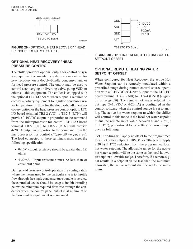
FIGURE 29 - OPTIONAL HEAT RECOVERY / HEAD PRESSURE CONTROL OUTPUT
GND
RTN VO I/O
0-10V 4-20mA
1
TB2 LTC I/O Board
OPTIONAL HEAT RECOVERY / HEAD PRESSURE CONTROL
The chiller provides optional output for control of sys-tem equipment to maintain condenser temperature for heat recovery on a double-bundle condenser unit or for head pressure control. The output may be used to control a converging or diverting valve, pump VSD, or other suitable equipment. The chiller is equipped with the optional LTC I/O board when output is required to control auxiliary equipment to regulate condenser wa-ter temperature or flow for the double-bundle heat re-covery option or the head pressure control option. LTC I/O board terminal TB2-2 (VO) to TB2-3 (RTN) will provide 0-10VDC output in proportion to the command from the microprocessor for control. LTC I/O board terminal TB2-1 (IO) to TB2-3 (RTN) will provide 4-20mA output in proportion to the command from the microprocessor for control (Figure 29 on page 20). The load connected to these terminals must meet the following specification:
• 0-10V - Input resistance should be greater than 1K ohms.
• 4-20mA - Input resistance must be less than or equal 500 ohms.
During head pressure control operation in a configuration where the means used by the particular site is to throttle flow through the single condenser tube bundle in service, the controlled device should be setup to inhibit throttling below the minimum required flow rate through the con-denser when the control panel output is at minimum so the flow switch requirement is maintained.
LD14347
FIGURE 30 - OPTIONAL REMOTE HEATING WATER SETPOINT OFFSET
GND
A18
GND
A17
1
TB9 LTC I/O Board
0-10VDC or
4-20mAINPUT
}
OPTIONAL REMOTE HEATING WATER SETPOINT OFFSETWhen configured for Heat Recovery, the active Hot Water Setpoint can be remotely modulated within a prescribed range during remote control source opera-tion with a 0-10VDC or 4-20mA input to the LTC I/O board terminal TB9-3 (AI8) to TB9-4 (GND) (Figure 30 on page 20). The remote hot water setpoint in-put type (0-10VDC or 4-20mA) is configured in the control software when the control source is set to ana-log. The active hot water setpoint to which the chiller will control in this mode is the local hot water setpoint minus the remote input value between 0 and 20°F(0 to 11.1°C), proportional to the voltage or current input over its full range.
0VDC or 4mA will apply no offset to the programmed local hot water setpoint, 10VDC or 20mA will apply a 20°F(11.1°C) reduction from the programmed local hot water setpoint. The allowable range for the active hot water setpoint will be the same as the local hot wa-ter setpoint allowable range. Therefore, if a remote sig-nal results in a setpoint value less than the minimum allowable, the active setpoint shall be set to the mini-mum.
FORM 160.75-PW4 ISSUE DATE: 5/1/2017
JOHNSON CONTROLS 21
10. Lead selector and cycling control to provide simi-lar lead selection and cycling of lag units for three (3) units is available: Kit No. 366-44684D (see Product Drawing Form 160.00-PA1.1) in NEMA I enclosure. Consult your Johnson Controls rep-resentative.
11. Sequence control kits (Figure 12 on page 11 andNote10)assumeaconstantchilledwaterflowand a constant leaving chilled water temperature to sense the cooling load. Sequence control kits arenotdesignedforvariablechilledwaterfloworwith reset of the leaving chilled water temperature – see Figure 21 on page 16, Figure 22 on page 16, Figure 23 on page 17, and Note 2.
12. Maximum allowable current draw between cir-cuits 24 and 2 for field installed devices is2 amp holding and 10 amps inrush – see OptiV-iew™ Control Center Wiring Diagram Form No. in Note 1.
13. Forrequiredfieldwiringconnectionsofthechilledwater pump contacts (terminals 44 and 45 on OptiView™ControlCenterfieldwiringterminalblockTB2)andchilledwaterflowswitch(termi-nals 1 and 12 on OptiView™ Control Cen-terfieldwiringterminalboardTB2),seeWiringDiagram – Field Connections: For those chillers that are not equipped with “P” code compressors, refer to the following Product Drawings: 160.54-PW4 (Electro-Mechanical Starter), 160.54-PW5 (YORK Solid State Starter), 160.54-PW6 (YORK Variable Speed Drive). For those chillers equipped with “P” code compressors, refer to the follow-ing Product Drawings; 160.54-PW11 (Electro-Mechanical Starter), 160.54-PW12 (YORK Solid State Starter), 160.54-PW13 (YORK Variable Speed Drive).
The Chilled Water Flow Switch is a safety con-trol. It must be connected to prevent operation of the chiller whenever chilled water flow is stopped. The use of the chilled water flow switch for pur-poses other than protection of the chiller may be accomplished in several ways. Two flow switch-es, a flow switch and a relay or separate contacts on the same flow switch.
14.
15. Do not apply voltage on field wiring terminalblocks TB4 and TB6 in YORK OptiView™ Con-trol Center, as 115VAC source is fed from termi-nals 1 and 2 .
1. These Figures show recommended field controlwiringmodifications (by others) to the standardOptiView™ Control Center Wiring Diagram. For those chillers that are not equipped with “P” code compressors, refer to the following Product Draw-ings: 160.54-PW4 (Electro-Mechanical Starter), 160.54-PW5 (YORK Solid State Starter), 160.54-PW6 (YORK Variable Speed Drive). For those chillers equipped with “P” code compressors, refer to the following Product Drawings; 160.54-PW11 (Electro-Mechanical Starter), 160.54-PW12 (YORK Solid State Starter), 160.54-PW13 (YORK Variable Speed Drive).
2. Ifmore thanoneof thesemodifications is tobeutilized with a particular unit, additional consid-eration must be given to the application to insure proper functioning of the control system. Consult your Johnson Controls representative.
3. The additional controls and wiring for these modi-ficationsare tobe furnishedand installed in thefieldbyothers(seeWarningonpage2).
5. All wiring shall be in accordance with the Nation-al Electrical Code, and applicable State and Local Codes.
6. Each115VACfieldconnectedinductiveload,i.e.,relay coil, motor starter coil, etc., shall have a transient suppressor wired (by others) in parallel with its coil, physically located at the coil. Spare transient suppressors are furnished in a bag in the OptiView™ Control Center.
7. The OptiView™ Control Center is factory fur-nished for Manual Restart After Power Failure as a standard function. The control center can be field changed fromManualRestart toAutoRe-start after a power failure by a service technician using a service level password to access the SET-POINTS > SETUP screen.
8. Two (2) unit controls schemes are suitable for 8°(4.4°C) – 12°F(6.7°C) water range. Constant chilled water flow is assumed at all loads. Forother requirements contact your Johnson Controls representative.