AFRL-RX-TY-TR-2010-0033 FIELD DEMONSTRATION OF A CENTRIFUGAL ULTRA HIGH PRESSURE (UHP) P-19 Jennifer L. Schroeder Fire Science Solutions, LLC 9117 Sunshine Drive Youngstown, FL 32466 Michael J. McDonald Applied Research Associates, Inc P.O. Box 40128 Tyndall Air Force Base, FL 32403 John R. Hawk and R. Craig Mellerski Air Force Research Laboratory 139 Barnes Drive, Suite 2 Tyndall AFB, FL 32403 Contract No. FA4819-07-D-0001 MARCH 2010 AIR FORCE RESEARCH LABORATORY MATERIALS AND MANUFACTURING DIRECTORATE Air Force Materiel Command United States Air Force Tyndall Air Force Base, FL 32403-5323 DISTRIBUTION A: Approved for public release; distribution unlimited.
Transcript
AFRL-RX-TY-TR-2010-0033
FIELD DEMONSTRATION OF A CENTRIFUGAL ULTRA HIGH PRESSURE (UHP) P-19
Jennifer L. Schroeder Fire Science Solutions, LLC 9117 Sunshine Drive Youngstown, FL 32466 Michael J. McDonald Applied Research Associates, Inc P.O. Box 40128 Tyndall Air Force Base, FL 32403 John R. Hawk and R. Craig Mellerski Air Force Research Laboratory 139 Barnes Drive, Suite 2 Tyndall AFB, FL 32403 Contract No. FA4819-07-D-0001 MARCH 2010
AIR FORCE RESEARCH LABORATORY MATERIALS AND MANUFACTURING DIRECTORATE
Air Force Materiel Command
United States Air Force Tyndall Air Force Base, FL 32403-5323
DISTRIBUTION A: Approved for public release; distribution unlimited.
NOTICE AND SIGNATURE PAGE Using Government drawings, specifications, or other data included in this document for any purpose other than Government procurement does not in any way obligate the U.S. Government. The fact that the Government formulated or supplied the drawings, specifications, or other data does not license the holder or any other person or corporation; or convey any rights or permission to manufacture, use, or sell any patented invention that may relate to them. This report was cleared for public release by the Air Force Research Laboratory, Materials and Manufacturing Directorate, Airbase Technologies Division, Public Affairs and is available to the general public, including foreign nationals. Copies may be obtained from the Defense Technical Information Center (DTIC) (http://www.dtic.mil). REPORT NUMBER AFRL-RX-TY-TR-2010-0033 HAS BEEN REVIEWED AND IS APPROVED FOR PUBLICATION IN ACCORDANCE WITH ASSIGNED DISTRIBUTION STATEMENT. ___//SIGNATURE//______________________ ___//SIGNATURE//______________________ R. CRAIG MELLERSKI, DR-III SANDRA R. MEEKER, DR-IV Work Unit Manager Chief, Deployed Base Systems Branch ___//SIGNATURE//______________________ ALBERT N. RHODES, PhD Acting Chief, Airbase Technologies Division This report is published in the interest of scientific and technical information exchange, and its publication does not constitute the Government’s approval or disapproval of its ideas or findings.
Standard Form 298 (Rev. 8/98)
REPORT DOCUMENTATION PAGE
Prescribed by ANSI Std. Z39.18
Form Approved OMB No. 0704-0188
The public reporting burden for this collection of information is estimated to average 1 hour per response, including the time for reviewing instructions, searching existing data sources, gathering and maintaining the data needed, and completing and reviewing the collection of information. Send comments regarding this burden estimate or any other aspect of this collection of information, including suggestions for reducing the burden, to Department of Defense, Washington Headquarters Services, Directorate for Information Operations and Reports (0704-0188), 1215 Jefferson Davis Highway, Suite 1204, Arlington, VA 22202-4302. Respondents should be aware that notwithstanding any other provision of law, no person shall be subject to any penalty for failing to comply with a collection of information if it does not display a currently valid OMB control number. PLEASE DO NOT RETURN YOUR FORM TO THE ABOVE ADDRESS. 1. REPORT DATE (DD-MM-YYYY) 2. REPORT TYPE 3. DATES COVERED (From - To)
4. TITLE AND SUBTITLE 5a. CONTRACT NUMBER
5b. GRANT NUMBER
5c. PROGRAM ELEMENT NUMBER
5d. PROJECT NUMBER
5e. TASK NUMBER
5f. WORK UNIT NUMBER
6. AUTHOR(S)
7. PERFORMING ORGANIZATION NAME(S) AND ADDRESS(ES) 8. PERFORMING ORGANIZATION REPORT NUMBER
9. SPONSORING/MONITORING AGENCY NAME(S) AND ADDRESS(ES) 10. SPONSOR/MONITOR'S ACRONYM(S)
11. SPONSOR/MONITOR'S REPORT NUMBER(S)
12. DISTRIBUTION/AVAILABILITY STATEMENT
13. SUPPLEMENTARY NOTES
14. ABSTRACT
15. SUBJECT TERMS
16. SECURITY CLASSIFICATION OF: a. REPORT b. ABSTRACT c. THIS PAGE
17. LIMITATION OF ABSTRACT
18. NUMBER OF PAGES
19a. NAME OF RESPONSIBLE PERSON
19b. TELEPHONE NUMBER (Include area code)
iii
TABLE OF CONTENTS
Section Page
LIST OF FIGURES ........................................................................................................................ v
LIST OF TABLES ......................................................................................................................... vi PREFACE ..................................................................................................................................... vii 1.0 INTRODUCTION ............................................................................................................... 1
SUMMARY .................................................................................................................................... 3 2.1 Phase I Vehicle Description ............................................................................................. 3
2.2 Phase I Testing ................................................................................................................. 5 2.3 Phase I Conclusions ......................................................................................................... 5
2.4 Phase I Recommendations ............................................................................................... 6 3.0 PHASE II; FIELD DEMONSTRATION OF FIVE MODIFIED P-19’S SUMMARY ...... 7
3.1 UHP P-19c Demonstration Locations .............................................................................. 7 3.2 Training ............................................................................................................................ 7 3.3 UHP P-19c Field Demonstration Overview ..................................................................... 7
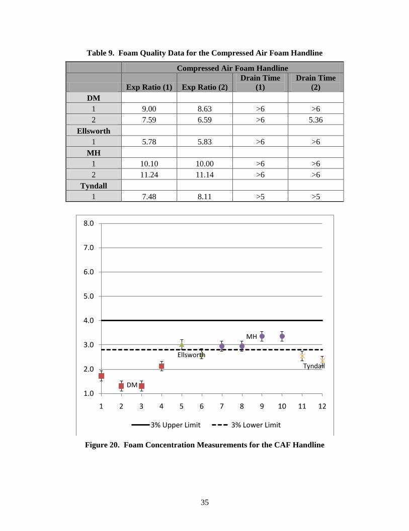
3.4 Foam Quality Methods and Results ................................................................................. 7 3.5 Pump Cycle Methods and Results .................................................................................... 8
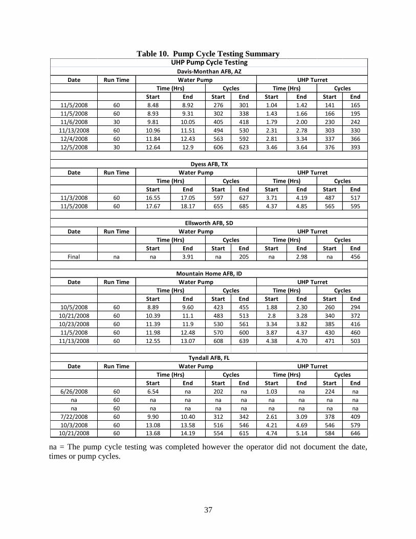
3.6 Three-Dimensional Engine Nacelle Fire Methods and Results ....................................... 8 3.7 Pool Fire Methods and Results ........................................................................................ 9 3.8 Cold Weather Evaluations ................................................................................................ 9
3.9 Design Issues Identified During Testing ........................................................................ 10
4.0 PHASE II; FIELD DEMONSTRATION OF FIVE MODIFIED P-19’S .......................... 11 4.1 Hardware Components ................................................................................................... 11
4.2 UHP P-19c Demonstration Locations ............................................................................ 17 4.3 Training .......................................................................................................................... 20 4.4 UHP P-19c Field Demonstration Overview ................................................................... 21 4.5 Instrumentation and Equipment ..................................................................................... 22 4.6 Foam Quality Methods and Results ............................................................................... 23
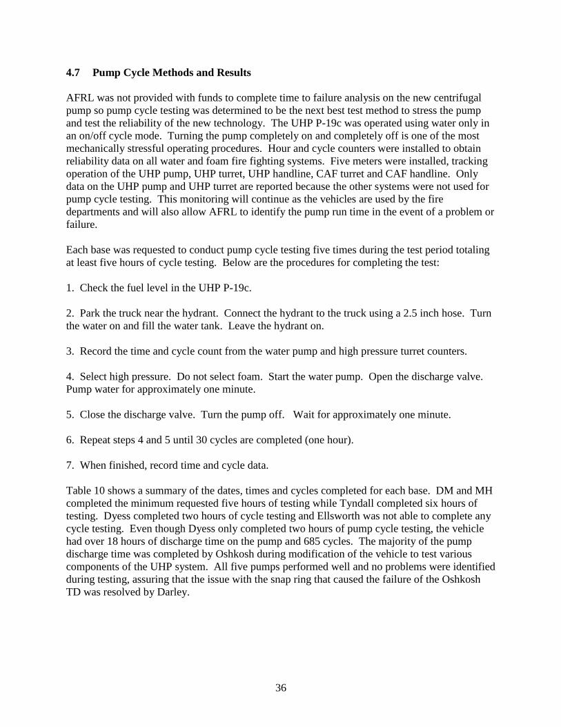
4.7 Pump Cycle Methods and Results .................................................................................. 36 4.8 Three-Dimensional Engine Nacelle Fire Methods and Results ..................................... 38
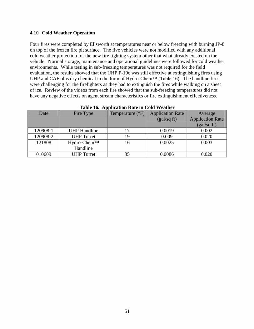
4.9 Pool Fire Methods and Results ...................................................................................... 40 4.10 Cold Weather Operation ............................................................................................. 51 4.11 Design Issues Identified During Testing .................................................................... 52
4.11.1 Compressed Air Foam System................................................................................ 52 4.11.2 UHP Handline and Turret Operation ...................................................................... 53 4.11.3 Pump and Roll in Handline Mode .......................................................................... 53
iv
4.11.4 Handline Operations and Problems with the Gear Shift ......................................... 54
4.12 Field Demonstration Database .................................................................................... 55 5.0 CONCLUSIONS................................................................................................................ 56 6.0 RECOMMENDATIONS ................................................................................................... 58 7.0 REFERENCES .................................................................................................................. 60 APPENDIX A - Memorandum from W.S. Darley & Co on the CRADA TD Pump Failure....... 61
APPENDIX B - Correspondence from Elkhart Brass on UHP Nozzle Redesign ........................ 62 APPENDIX C - Oshkosh Engineering Technical Reports ........................................................... 64 APPENDIX D - Refractometer Calibration Curves ..................................................................... 75 APPENDIX E - Phase II Field Prototype Data ............................................................................. 77
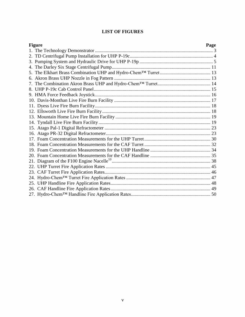
1. The Technology Demonstrator .................................................................................................. 3
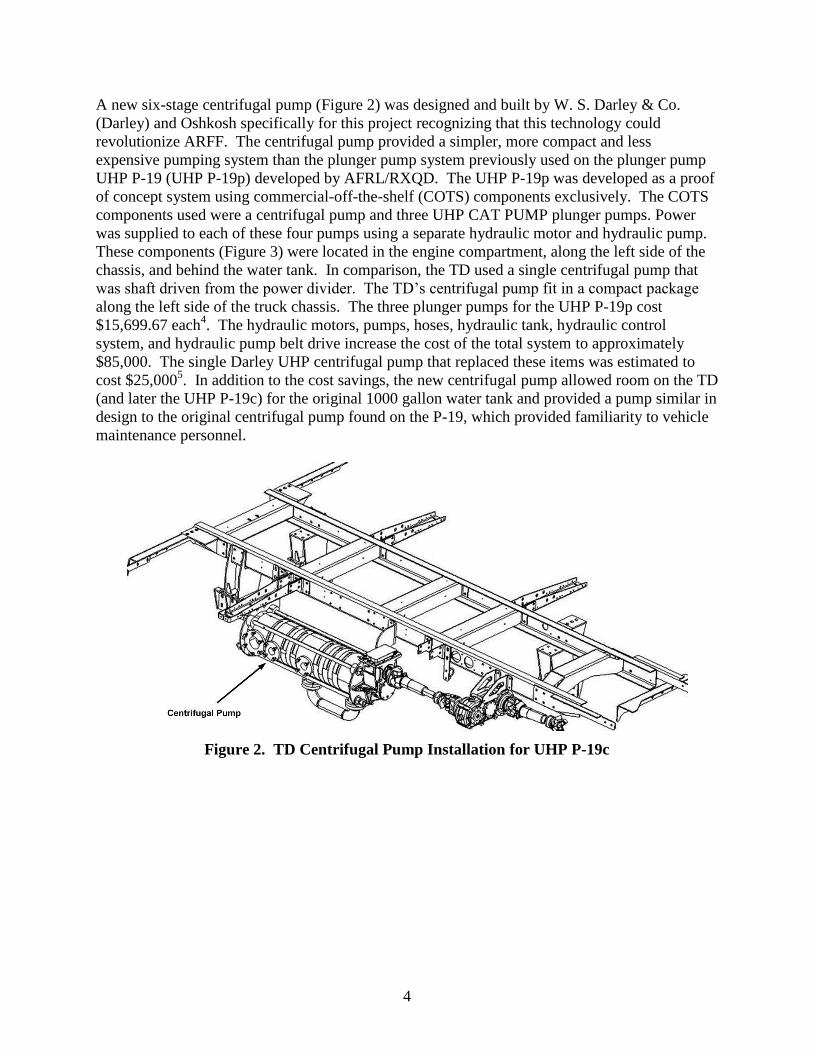
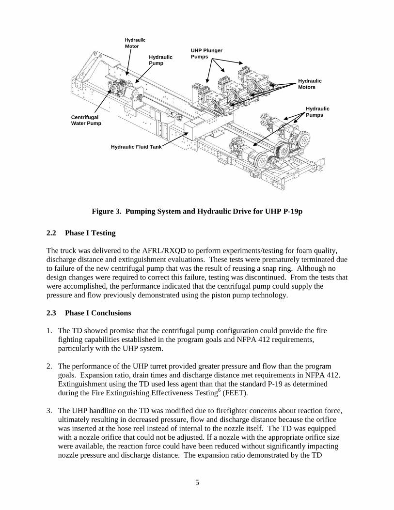
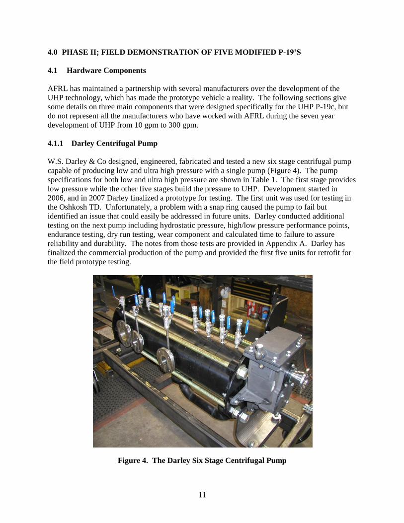
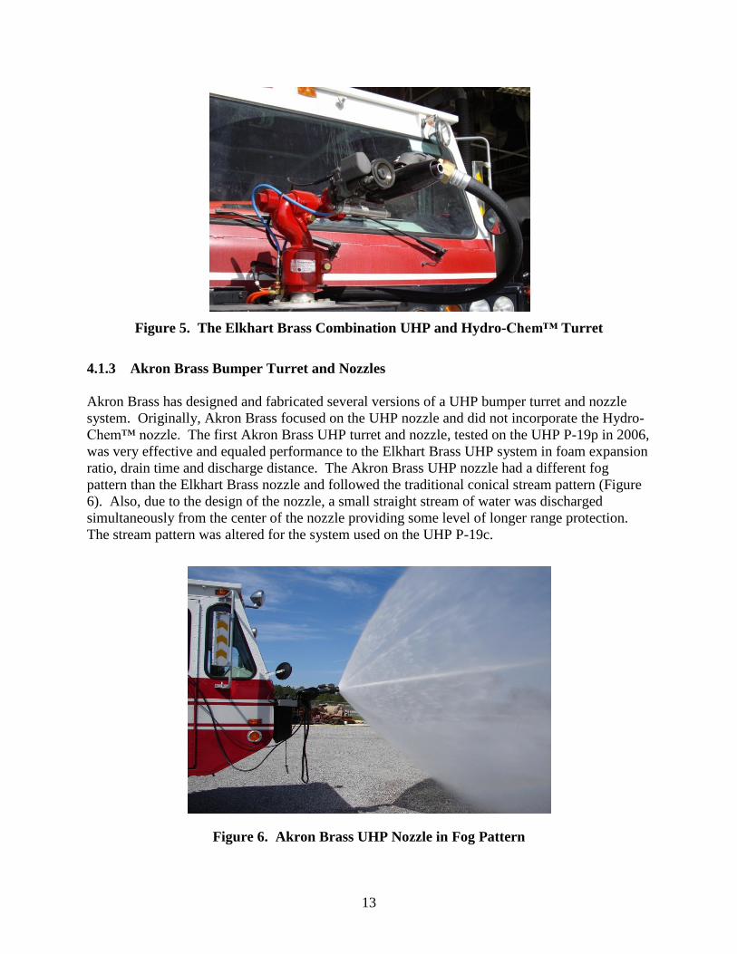
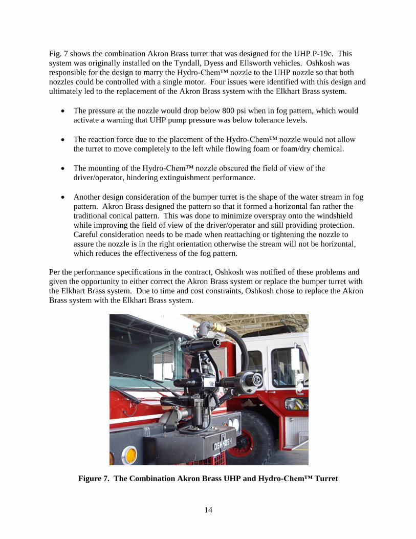
2. TD Centrifugal Pump Installation for UHP P-19c ..................................................................... 4 3. Pumping System and Hydraulic Drive for UHP P-19p ............................................................. 5 4. The Darley Six Stage Centrifugal Pump .................................................................................. 11 5. The Elkhart Brass Combination UHP and Hydro-Chem™ Turret .......................................... 13 6. Akron Brass UHP Nozzle in Fog Pattern ................................................................................ 13
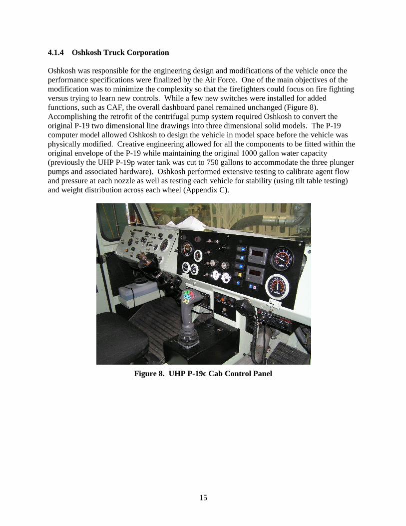
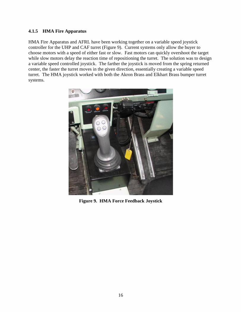
7. The Combination Akron Brass UHP and Hydro-Chem™ Turret............................................ 14 8. UHP P-19c Cab Control Panel ................................................................................................. 15 9. HMA Force Feedback Joystick ................................................................................................ 16 10. Davis-Monthan Live Fire Burn Facility ................................................................................ 17
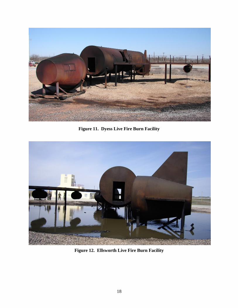
11. Dyess Live Fire Burn Facility ................................................................................................ 18 12. Ellsworth Live Fire Burn Facility .......................................................................................... 18
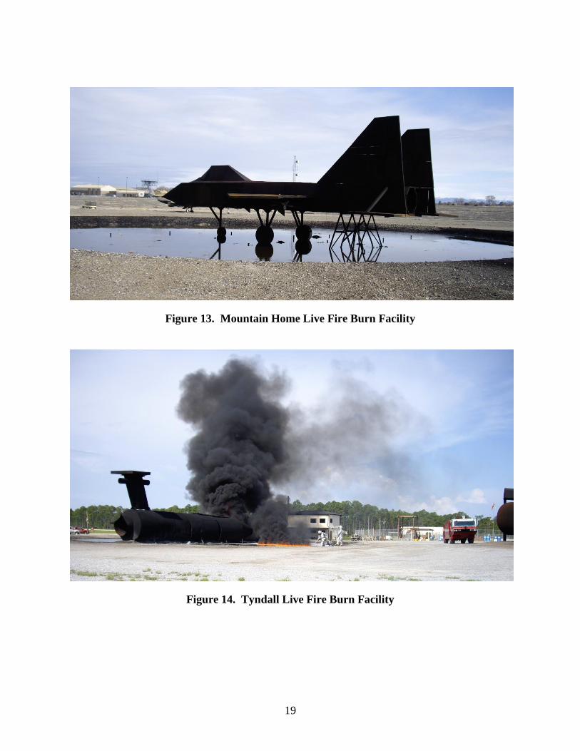
13. Mountain Home Live Fire Burn Facility ............................................................................... 19 14. Tyndall Live Fire Burn Facility ............................................................................................. 19
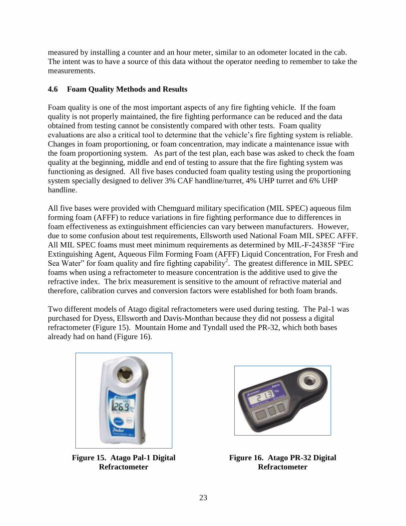
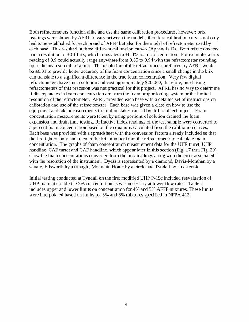
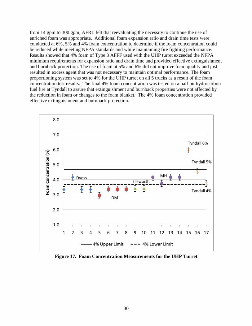
15. Atago Pal-1 Digital Refractometer ........................................................................................ 23 16. Atago PR-32 Digital Refractometer....................................................................................... 23 17. Foam Concentration Measurements for the UHP Turret ....................................................... 30
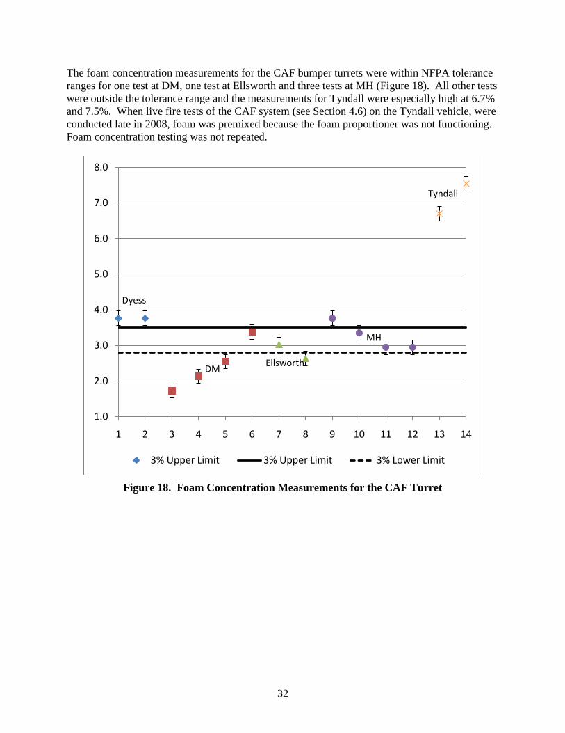
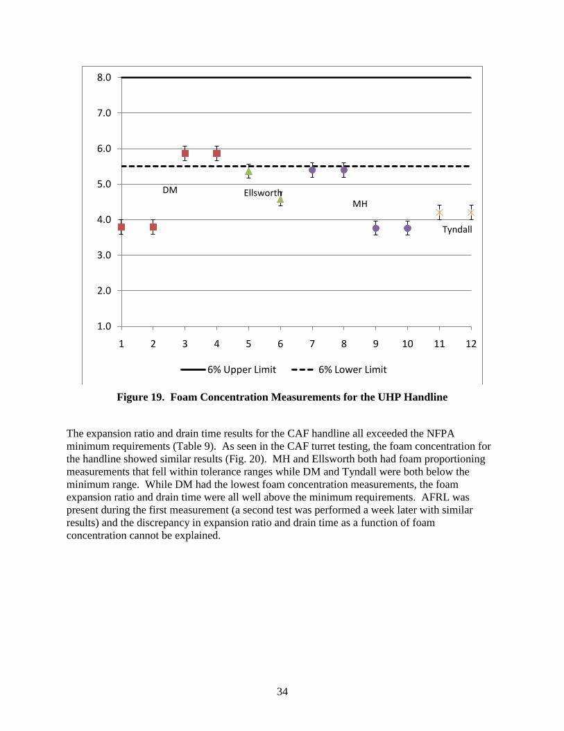
18. Foam Concentration Measurements for the CAF Turret ....................................................... 32 19. Foam Concentration Measurements for the UHP Handline .................................................. 34
20. Foam Concentration Measurements for the CAF Handline .................................................. 35 21. Diagram of the F100 Engine Nacelle
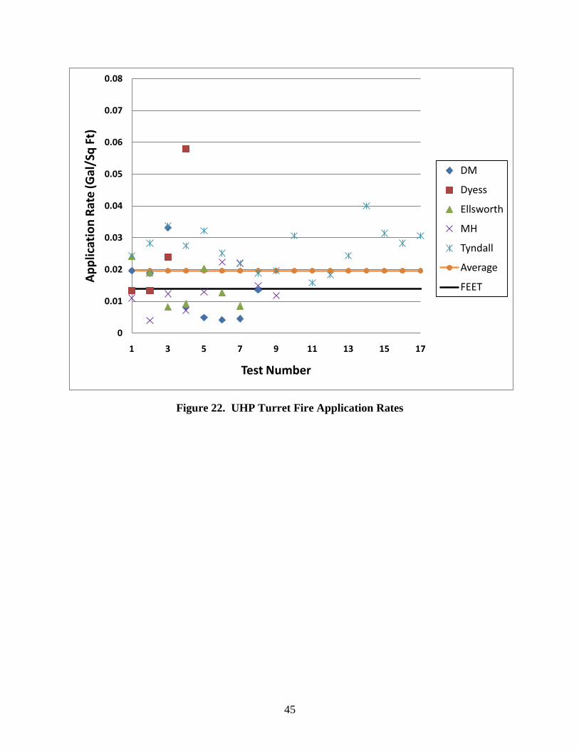
22. UHP Turret Fire Application Rates ....................................................................................... 45
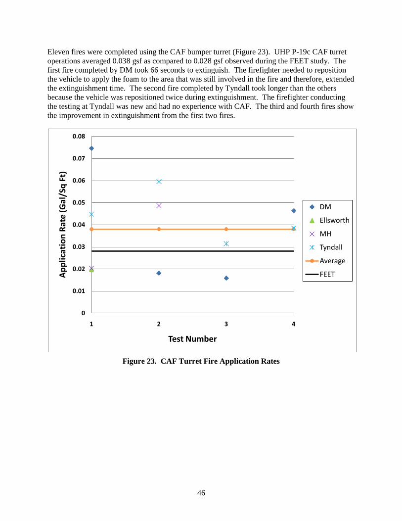
23. CAF Turret Fire Application Rates........................................................................................ 46
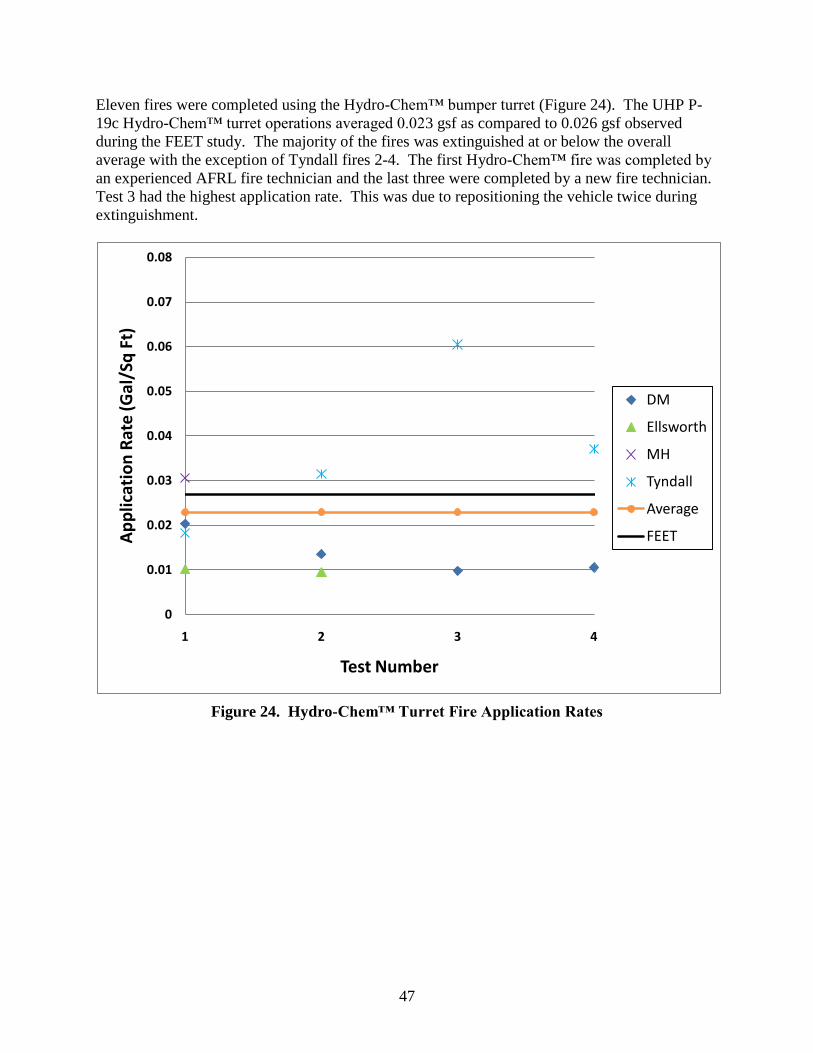
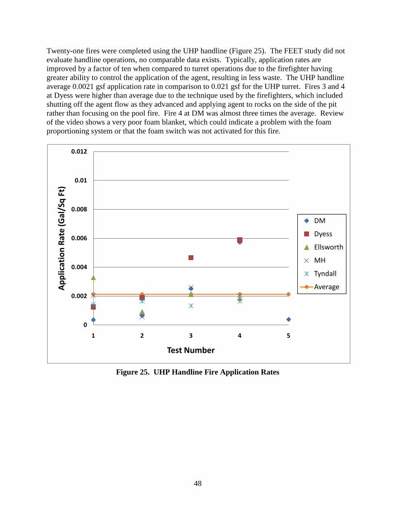
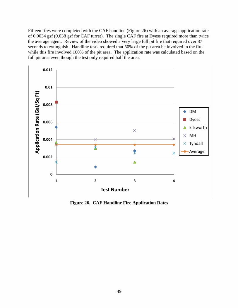
24. Hydro-Chem™ Turret Fire Application Rates ...................................................................... 47 25. UHP Handline Fire Application Rates ................................................................................... 48 26. CAF Handline Fire Application Rates ................................................................................... 49
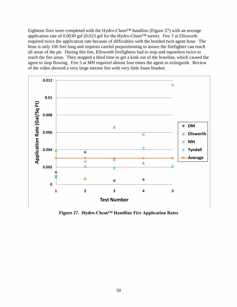
27. Hydro-Chem™ Handline Fire Application Rates .................................................................. 50
vi
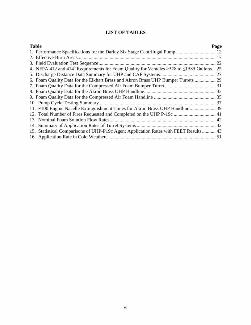
LIST OF TABLES
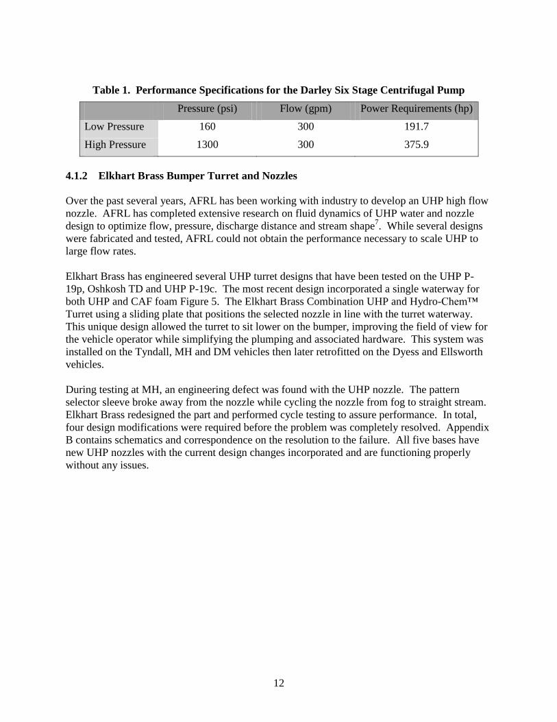
Table Page 1. Performance Specifications for the Darley Six Stage Centrifugal Pump ................................ 12
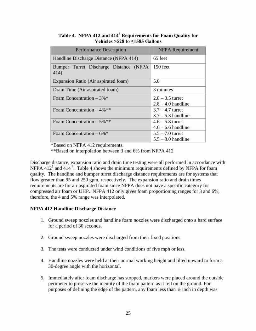
2. Effective Burn Areas................................................................................................................ 17 3. Field Evaluation Test Sequence ............................................................................................... 22 4. NFPA 412 and 414
8 Requirements for Foam Quality for Vehicles >528 to ≤1585 Gallons... 25
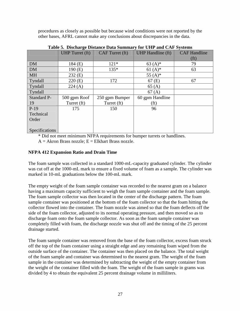
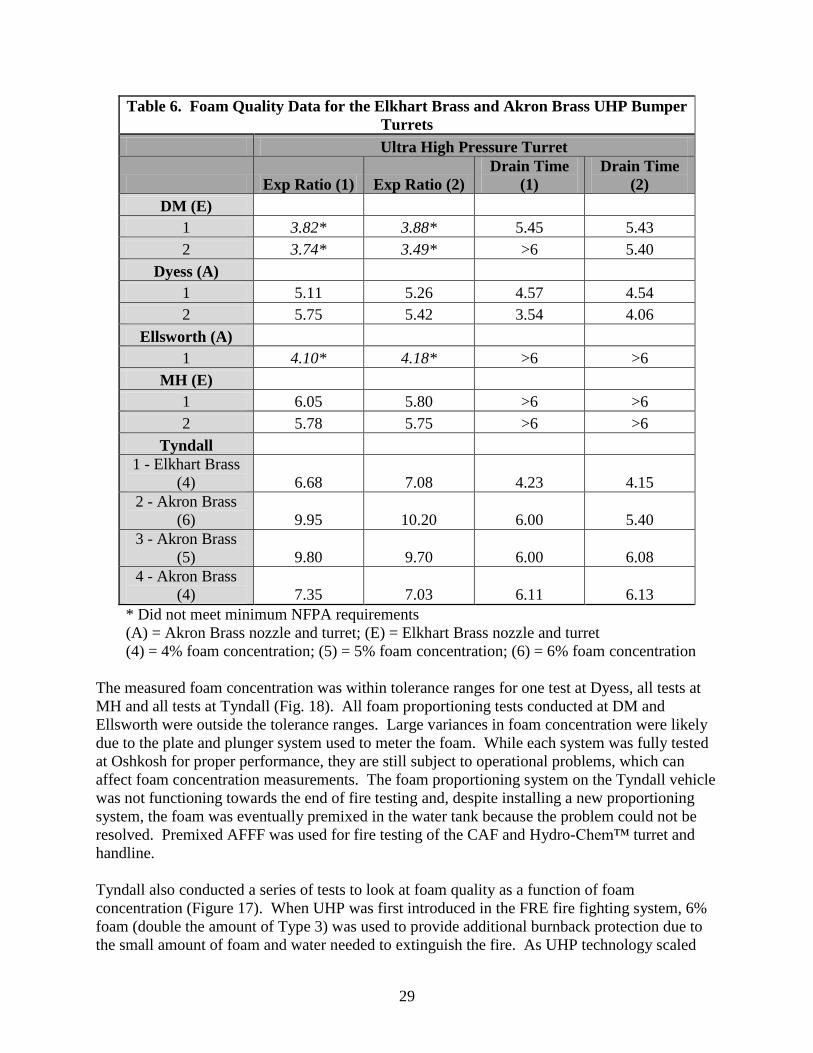
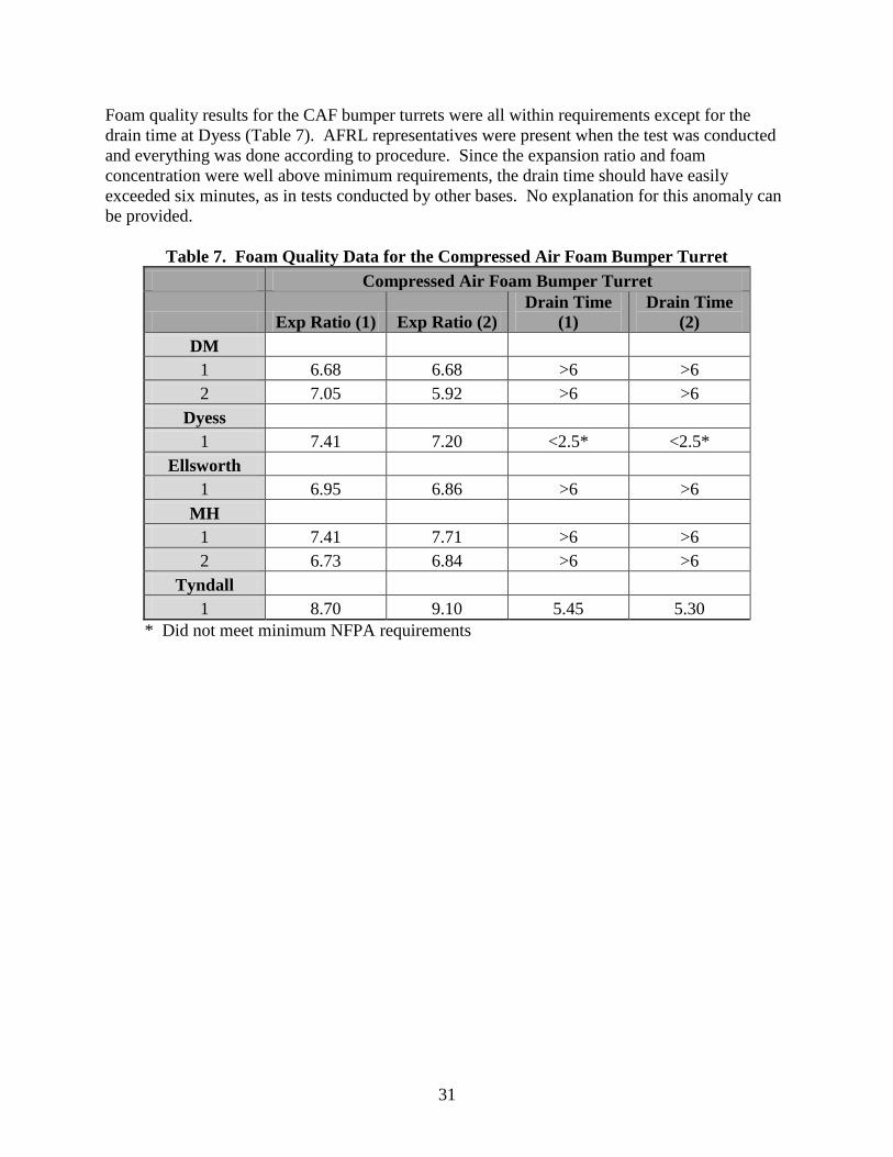
5. Discharge Distance Data Summary for UHP and CAF Systems ............................................. 27 6. Foam Quality Data for the Elkhart Brass and Akron Brass UHP Bumper Turrets ................. 29
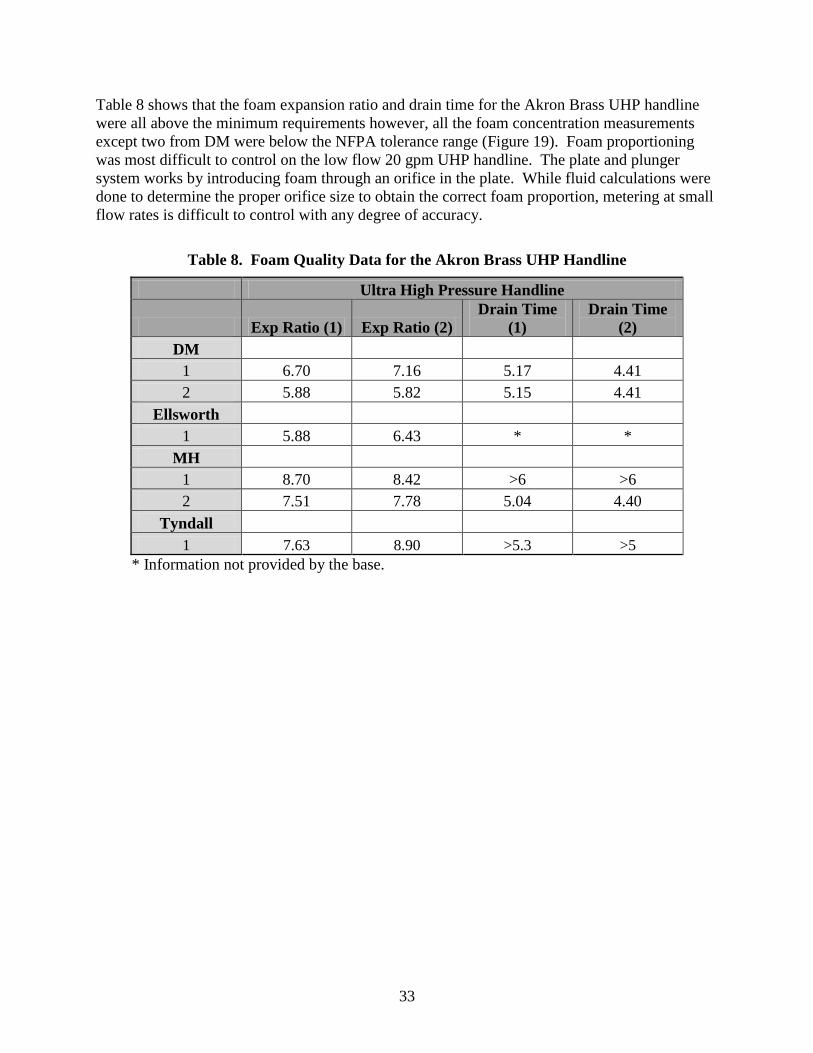
7. Foam Quality Data for the Compressed Air Foam Bumper Turret ......................................... 31 8. Foam Quality Data for the Akron Brass UHP Handline.......................................................... 33 9. Foam Quality Data for the Compressed Air Foam Handline .................................................. 35 10. Pump Cycle Testing Summary .............................................................................................. 37
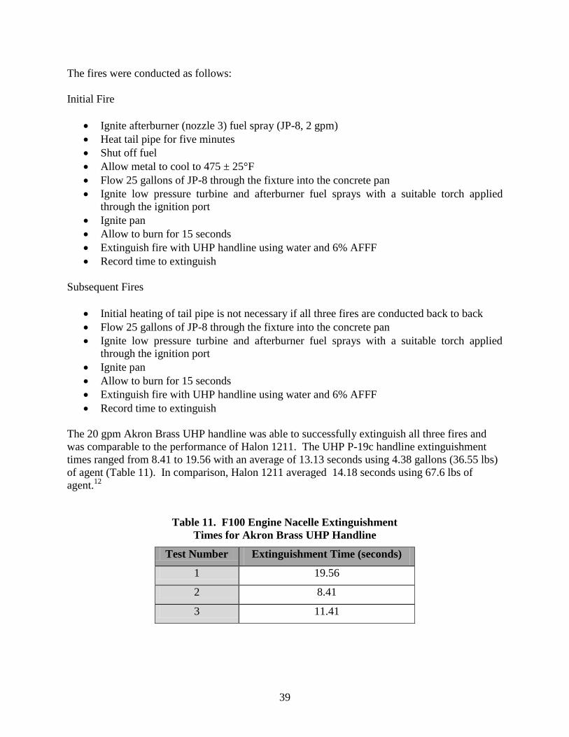
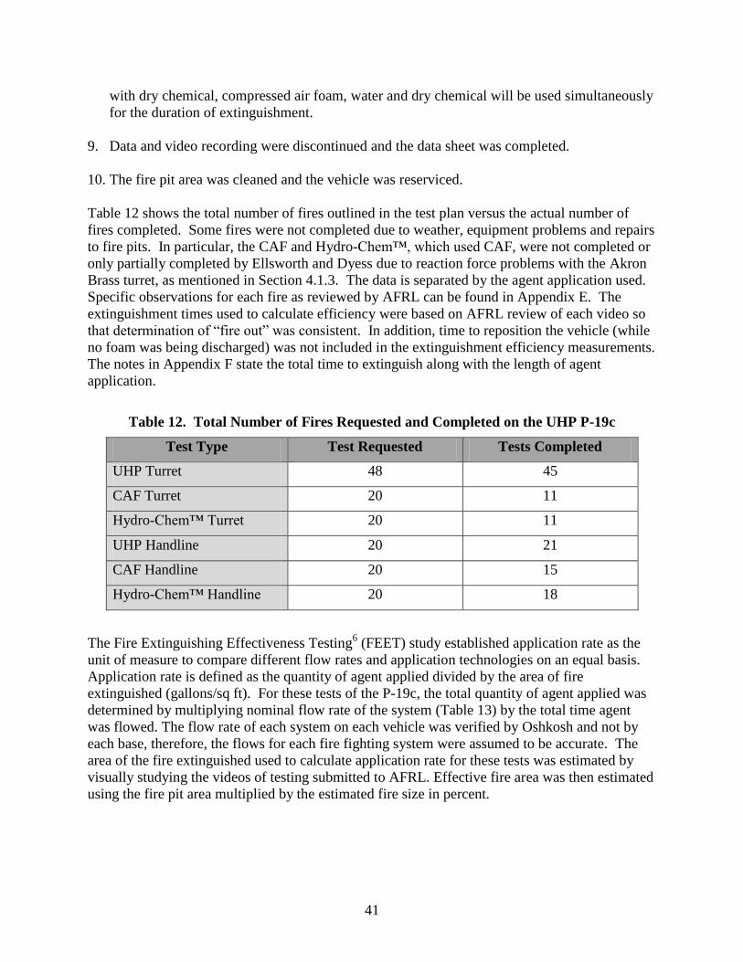
11. F100 Engine Nacelle Extinguishment Times for Akron Brass UHP Handline ..................... 39 12. Total Number of Fires Requested and Completed on the UHP P-19c .................................. 41
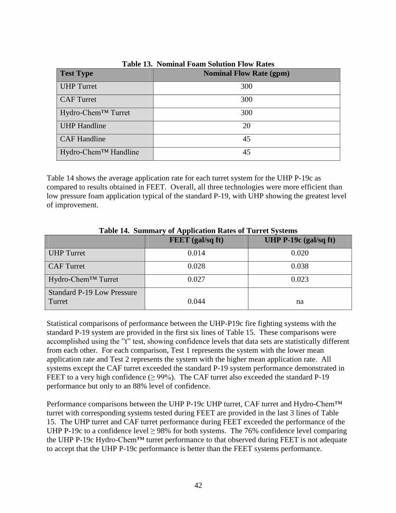
13. Nominal Foam Solution Flow Rates ...................................................................................... 42 14. Summary of Application Rates of Turret Systems ................................................................ 42
15. Statistical Comparisons of UHP-P19c Agent Application Rates with FEET Results ........... 43 16. Application Rate in Cold Weather ......................................................................................... 51
vii
PREFACE
This report details field demonstration of the Ultra High Pressure (UHP) fire fighting technology
that was initially researched and developed (R&D) by the Air Force Research Laboratory
(AFRL) in 2002. Over the past seven years, AFRL has conducted extensive R&D to scale UHP
from 10 gallons per minute (gpm) on the First Response Expeditionary (FRE) fire fighting
system to the 300 gpm system used for field evaluation in this report. The ultimate goal of UHP
technology was to develop a fire fighting system that exceeded the effectiveness of current
technology while reducing the amount of agent needed to extinguish a burning aircraft. AFRL
has shown through the careful scaling of the technology that a greater than 300% improvement
in fire fighting efficiency can be obtained using UHP. This is revolutionary technology
advancement.
AFRL would like to acknowledge several organizations for their contributions to this project
including the Air Force Civil Engineering Support Agency, the five Air Force bases Davis-
Kristopher., Casarez, Adrianna, and Carr, Virgil. The Development and Design of a
Prototype Ultra High Pressure P-19 Firefighting Vehicle. Defense Technical Information
Center. AFRL-ML-TY-TR-2007-4525. Feb 2007.
8. National Fire Protection Agency, NFPA 414: Standard for Aircraft Rescue and Fire-Fighting
Vehicles, 2007 Edition.
9. Air Force Technical Order 36A12-8-17-1. Aircraft Crash and Structural Firefighting Truck:
Operation and Operator Maintenance Instructions. USAF Type A/S32P-19 Technical
Manual: 11 January 1988.
10. Air Force Research Laboratory. Minimum Performance Requirement for Air Force
Flightline Fire Extinguishers: Extinguishing Performance Against 3-Dimensional and
Hidden Fires. Defense Technical Information Center. AFRL-ML-TY-TR-2002-4540. May
2002.
11. Bowman, H., Davidson, R., Verdonick, D., Darwin, R., Hawk, J., Dormer, K., and
Mullenhard, P. ESTCP Demonstration Plan Qualification of an Acceptable Alternative to
Halon 1211 DoD Flightline Extinguishers ESTCP Thrust Area: Pollution Prevention
(Material Substitution). Draft. Naval Air Warfare Center Weapons Division. ESTCP 06-D-
PP3-026. April 2008.
12. Dierdorf, D and J. Kiel. Halon Flightline Extinguisher Evaluation: Data Supporting
Standard Development. Defense Technical Information Center. AFRL-ML-TY-TR-2005-
4583. Oct 2005.
61
APPENDIX A - Memorandum from W.S. Darley & Co on the CRADA TD Pump Failure
In August, 2008 AFRL initiated a program to modify five P-19s with the Darley centrifugal
pump technology and conduct a series of tests under field conditions including foam quality,
pump cycling and fire extinguishment effectiveness. In the months following the conclusion of
the Oshkosh testing of the first centrifugal pump, Darley investigated the cause of the pump
failure and designed engineering and maintenance practices to assure this problem would not
happen with subsequent units. The following tests were completed by Darley to analyze pump
performance and identify potential failure modes:
1. The pump can withhold a hydrostatic pressure of 1950 psig for 15 minutes.
2. For the pump's high pressure performance point, the pump can attain 1240 psig while flowing
300 gpm through its 6th stage discharge. To operate at this test point, the pump must be
provided with shaft horsepower at 3550 rpm and the 1st stage discharge must be closed.
3. For the pump's low pressure performance point, the pump can attain 198 psig while flowing
300 gpm through its 1st stage discharge. To operate at this test point, the pump must be provided
with shaft horsepower at 3550 rpm. The 0.1360" orifice will flow approximately 20 gpm which
will experience a 50°F increase in temperature.
4. The pump was endurance tested for 20 hours of accumulated time by undergoing a repeated
cycle of operating at its high pressure performance point for 5 minutes followed by being
stopped for 5 minutes. This cycle was repeated intermittently (10 hour days) until the
accumulation of time that it was being operated at its high pressure performance point equaled
20 hours. The results of the endurance test showed we could lengthen the life of the large
mechanical seal by adding the element Antimony to the carbon pusher ring. After the endurance
test the pump was still functional.
5. The pump was drained of water and run dry for a period of 5 minutes at 3550 rpm. Running
dry is not a recommended practice but the test was conducted to see if the seal withstood the
abuse. After the running dry test, the pump passed a dry vacuum test by being able to hold a
static vacuum of 22 inches of mercury for 5 minutes.
6. The wear components of the pump consist of the four gear box bearings, three oil seals, two
mechanical water seals and 80W-90 gear box lubricant. The estimated time to replace all of
these wear components on a pump that has been removed from the truck is 2 hours.
7. The estimated time to failure (calculated L10 life) on the wear components is 1,375 hours
when operated at the high pressure performance point.
62
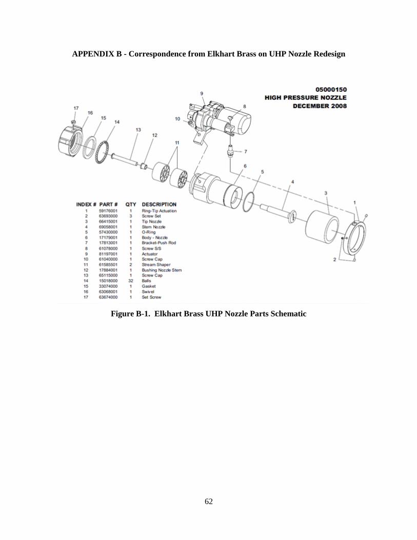
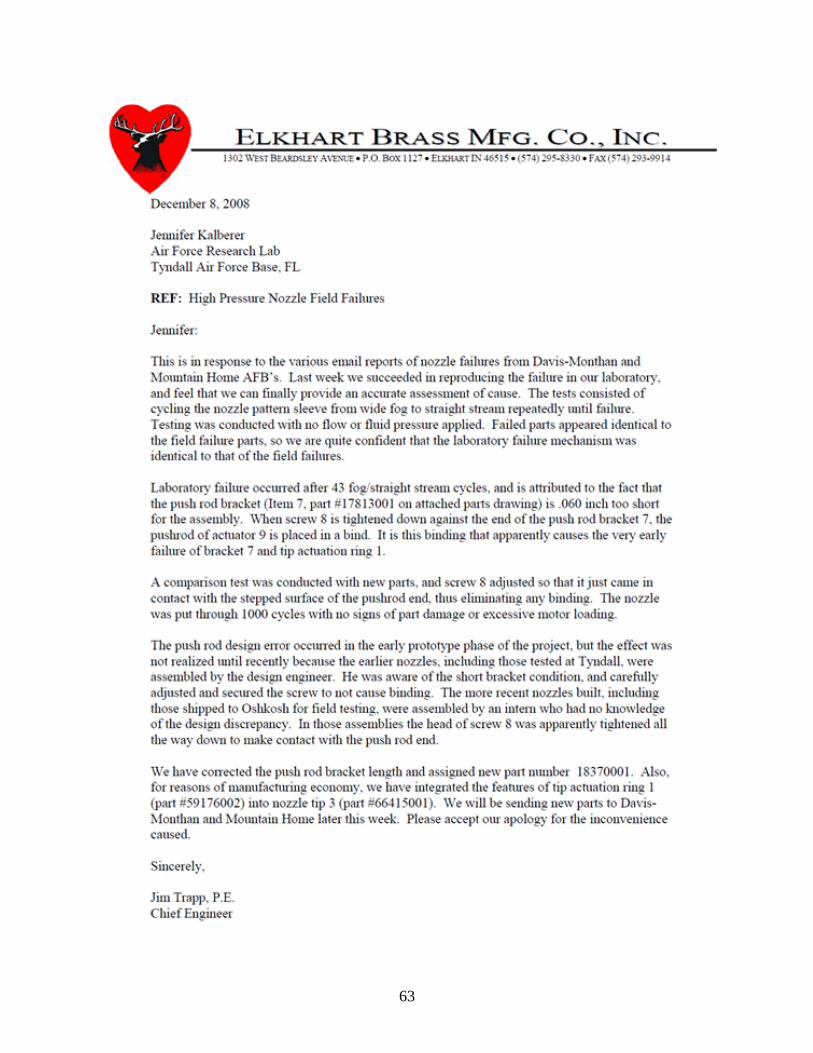
APPENDIX B - Correspondence from Elkhart Brass on UHP Nozzle Redesign
Figure B-1. Elkhart Brass UHP Nozzle Parts Schematic
63
64
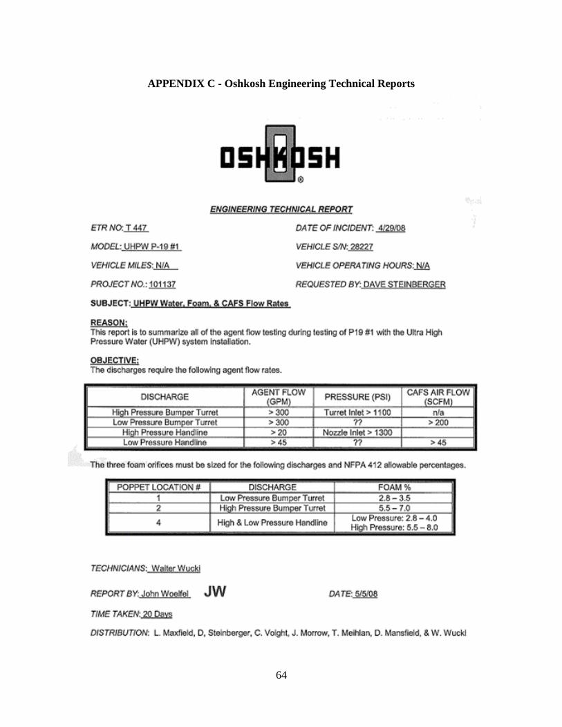
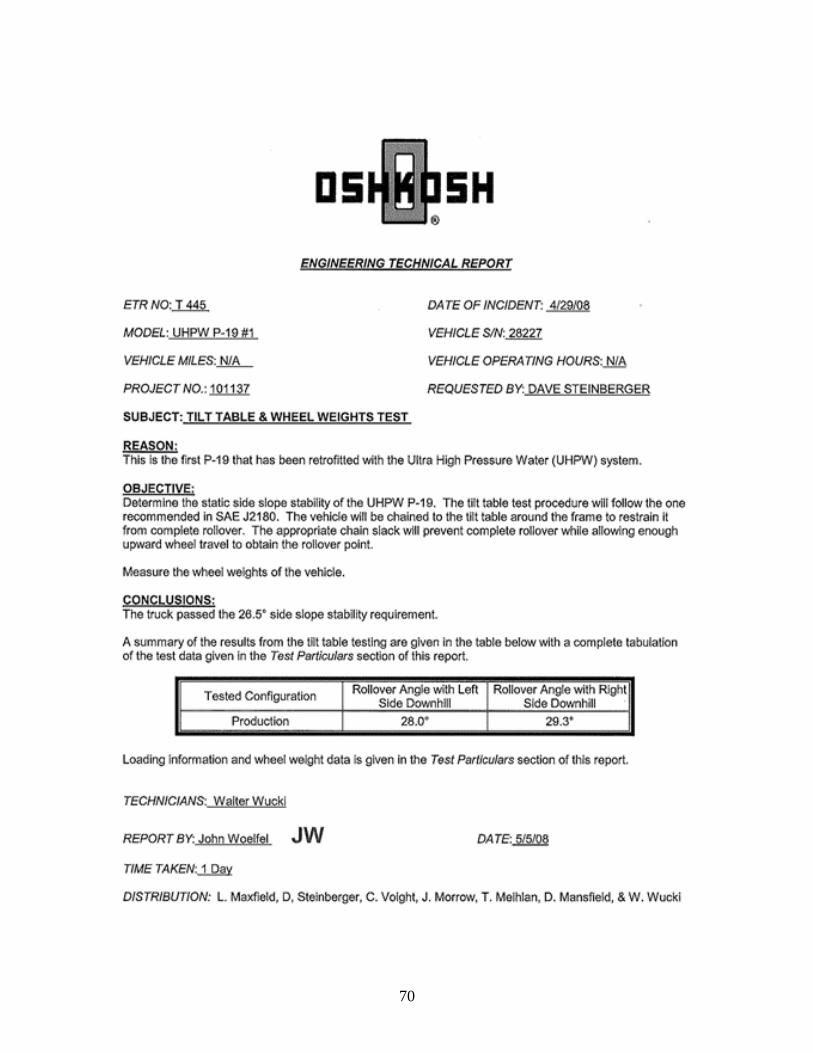
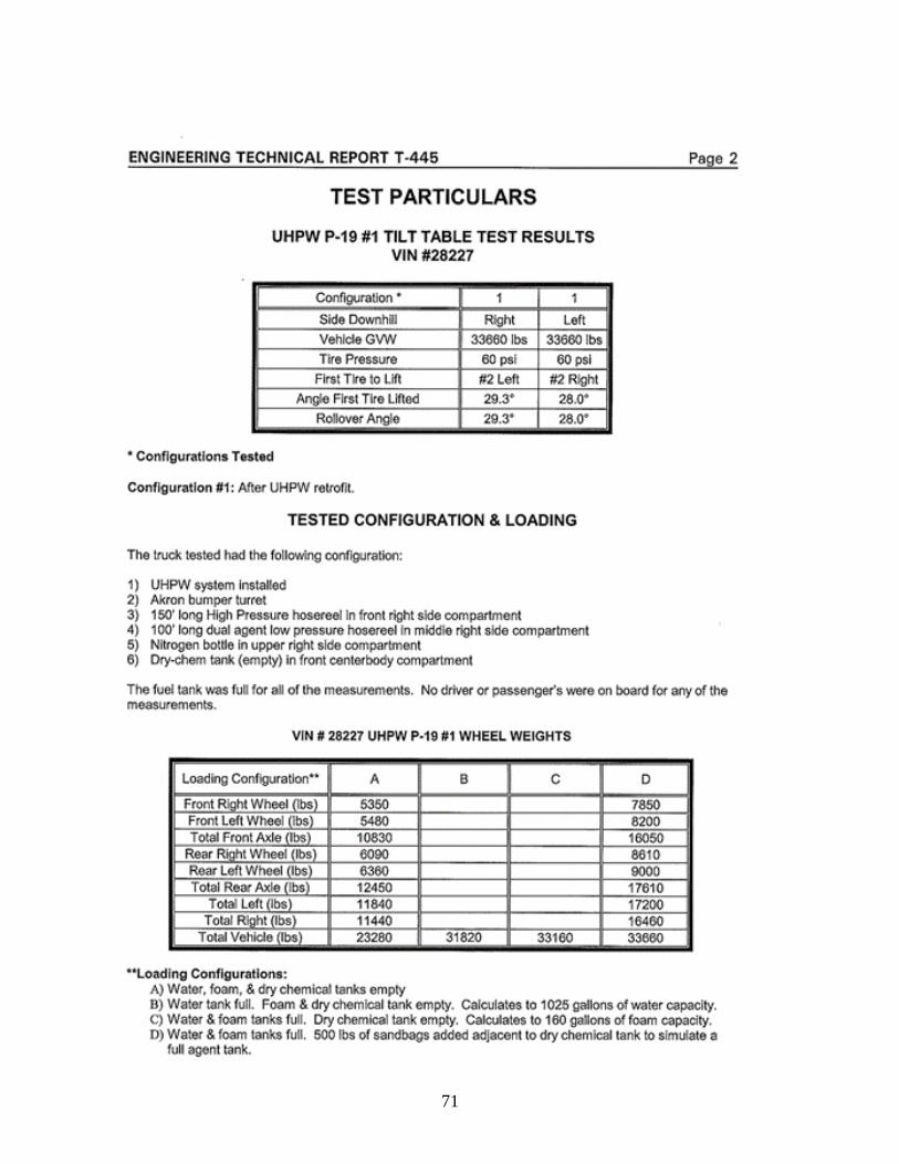
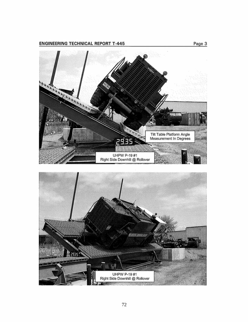
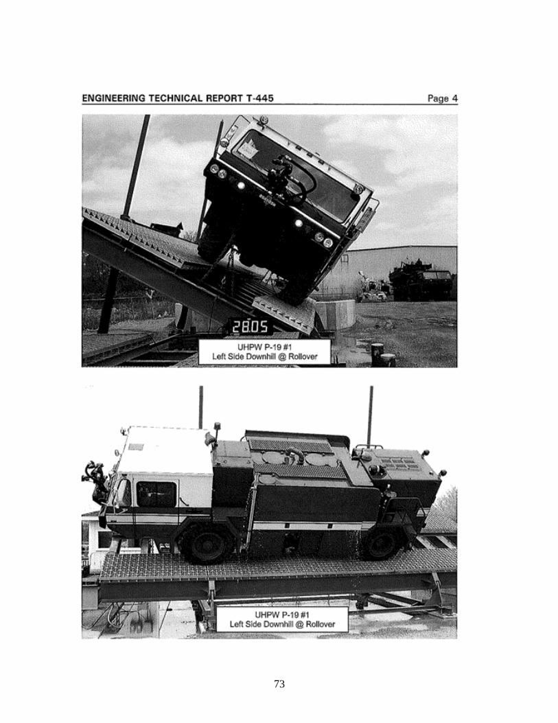
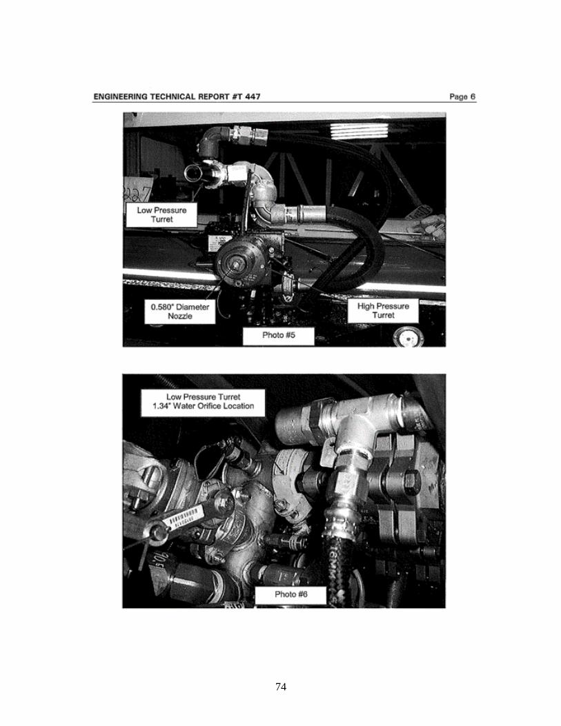
APPENDIX C - Oshkosh Engineering Technical Reports
65
66
67
68
69
70
71
72
73
74
75
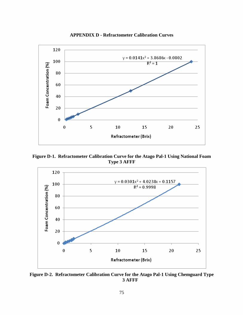
APPENDIX D - Refractometer Calibration Curves
Figure D-1. Refractometer Calibration Curve for the Atago Pal-1 Using National Foam
Type 3 AFFF
Figure D-2. Refractometer Calibration Curve for the Atago Pal-1 Using Chemguard Type
3 AFFF
76
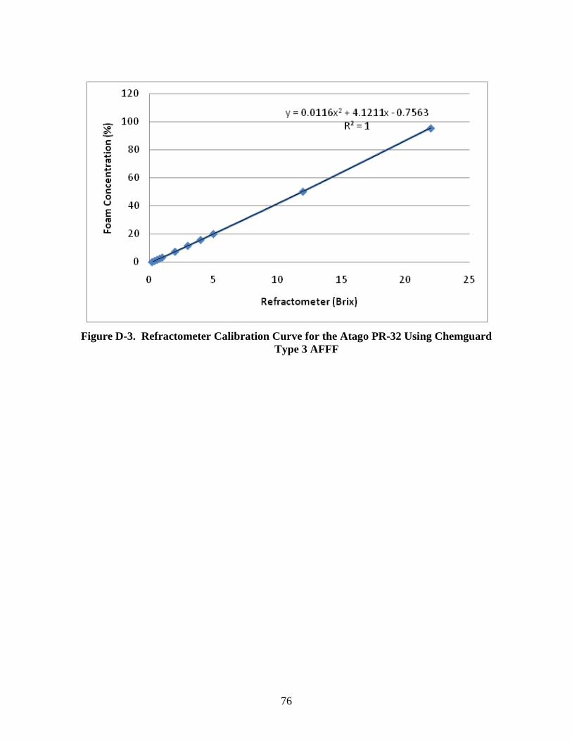
Figure D-3. Refractometer Calibration Curve for the Atago PR-32 Using Chemguard
Type 3 AFFF
77
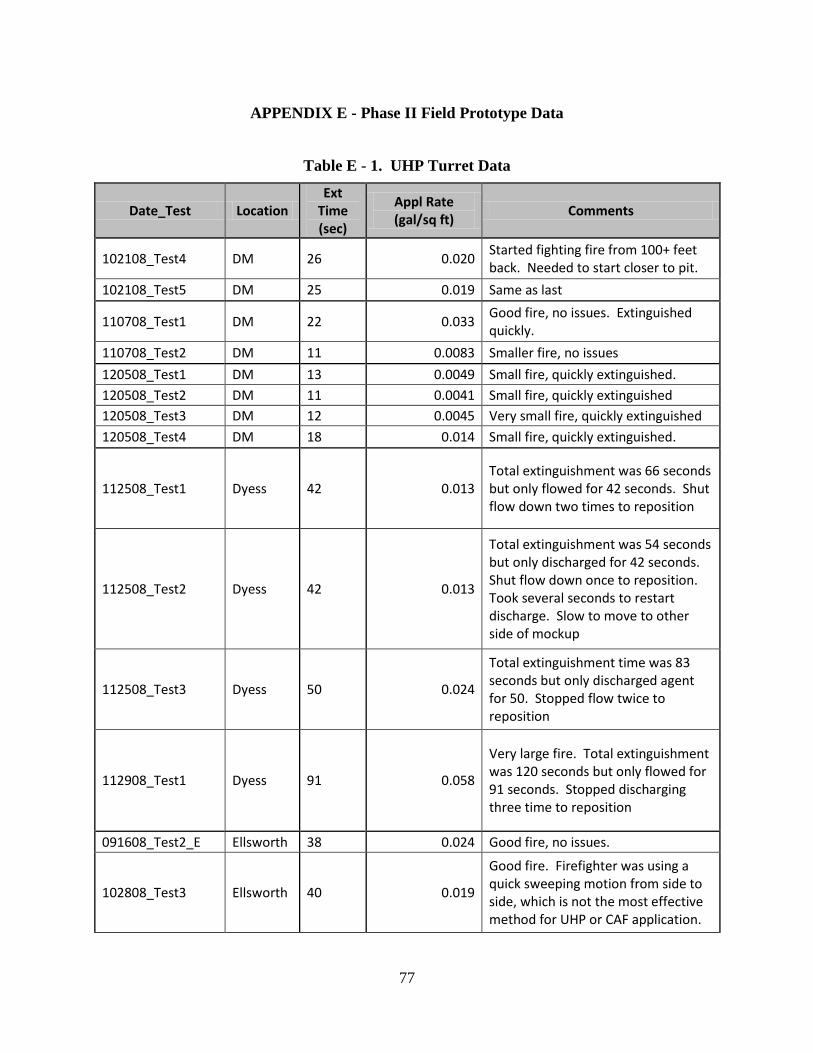
APPENDIX E - Phase II Field Prototype Data
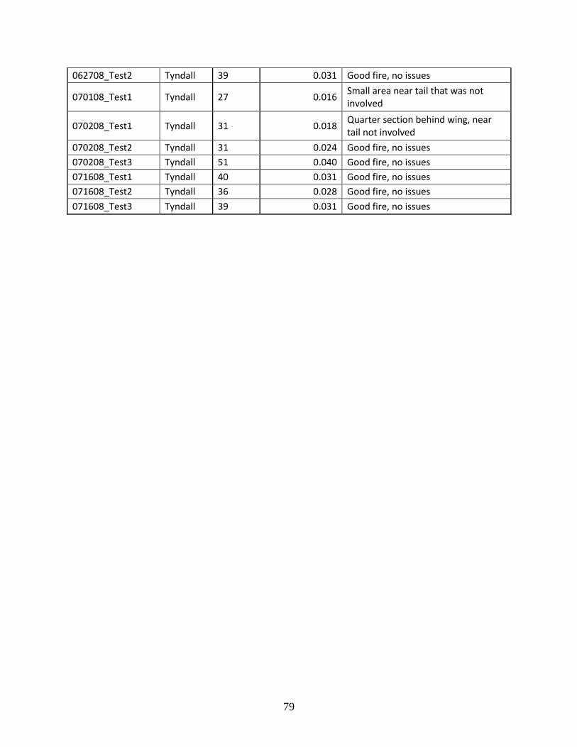
Table E - 1. UHP Turret Data
Date_Test Location Ext
Time (sec)
Appl Rate (gal/sq ft)
Comments
102108_Test4 DM 26 0.020 Started fighting fire from 100+ feet back. Needed to start closer to pit.
102108_Test5 DM 25 0.019 Same as last
110708_Test1 DM 22 0.033 Good fire, no issues. Extinguished quickly.
110708_Test2 DM 11 0.0083 Smaller fire, no issues
120508_Test1 DM 13 0.0049 Small fire, quickly extinguished.
120508_Test2 DM 11 0.0041 Small fire, quickly extinguished
120508_Test3 DM 12 0.0045 Very small fire, quickly extinguished
120508_Test4 DM 18 0.014 Small fire, quickly extinguished.
112508_Test1 Dyess 42 0.013 Total extinguishment was 66 seconds but only flowed for 42 seconds. Shut flow down two times to reposition
112508_Test2 Dyess 42 0.013
Total extinguishment was 54 seconds but only discharged for 42 seconds. Shut flow down once to reposition. Took several seconds to restart discharge. Slow to move to other side of mockup
112508_Test3 Dyess 50 0.024
Total extinguishment time was 83 seconds but only discharged agent for 50. Stopped flow twice to reposition
112908_Test1 Dyess 91 0.058
Very large fire. Total extinguishment was 120 seconds but only flowed for 91 seconds. Stopped discharging three time to reposition
091608_Test2_E Ellsworth 38 0.024 Good fire, no issues.
102808_Test3 Ellsworth 40 0.019
Good fire. Firefighter was using a quick sweeping motion from side to side, which is not the most effective method for UHP or CAF application.
78
102808_Test4 Ellsworth 26 0.0083 Good fire. Faster sweeping action but not as much as previous.
010609_Test2 Ellsworth 29 0.0092
Limited fire size due to ice in pit. Total extinguishment time was 44 seconds with 29 seconds of discharge.
112508_Test2_E Ellsworth 32 0.020 Good fire, no issues.
120208_Test2 Ellsworth 40 0.013
Total extinguishment time was 75 seconds but only discharged for 40 seconds. Stopped twice to reposition vehicle.
120908_Test2 Ellsworth 27 0.0086 Smaller fire due to ice in pit. Firefighter was very effective with technique.
091608_Test2 MH 14 0.011 Good fire, no issues
091708_Test2 MH 10 0.0039 Small fire for turret
100908_Test2 MH 21 0.012 Good fire, no issues
100908_Test3 MH 12 0.0071 Video ended before fire was out-check data sheet for time
102208_Test1_MH MH 22 0.013 Good fire, no issues
102208_Test2_MH MH 38 0.022 Little trouble getting last fire out in rocks
102308_Test1_MH MH 28 0.022
Good fire. Firefighter stopped short of the fire and could have extinguished more quickly if he continued application toward the back of the pit.
102808_Test1_MH MH 19 0.015 Good fire, no issues
102808_Test2_MH MH 20 0.012 Good fire, no issues
050508_Test1 Tyndall 31 0.024 First fire with UHP P-19c once delivered from OTC
050508_Test2 Tyndall 36 0.029 Fire with Gen Eulberg at controls
050608_Test1 Tyndall 43 0.034 Good fire, no issues
050608_Test2 Tyndall 35 0.028 Good fire, no issues
061708_Test1 Tyndall 41 0.032 Little fire left burning in rocks on side of fuselage
061708_Test2 Tyndall 32 0.025 Good fire, no issues
061708_Test3 Tyndall 31 0.022 Wind pushed fuel toward tail. Small area not involved at the nose
061708_Test4 Tyndall 24 0.019 Good fire, no issues
062708_Test1 Tyndall 25 0.020 Good fire, no issues
79
062708_Test2 Tyndall 39 0.031 Good fire, no issues
070108_Test1 Tyndall 27 0.016 Small area near tail that was not involved
070208_Test1 Tyndall 31 0.018 Quarter section behind wing, near tail not involved
070208_Test2 Tyndall 31 0.024 Good fire, no issues
070208_Test3 Tyndall 51 0.040 Good fire, no issues
071608_Test1 Tyndall 40 0.031 Good fire, no issues
071608_Test2 Tyndall 36 0.028 Good fire, no issues
071608_Test3 Tyndall 39 0.031 Good fire, no issues
80
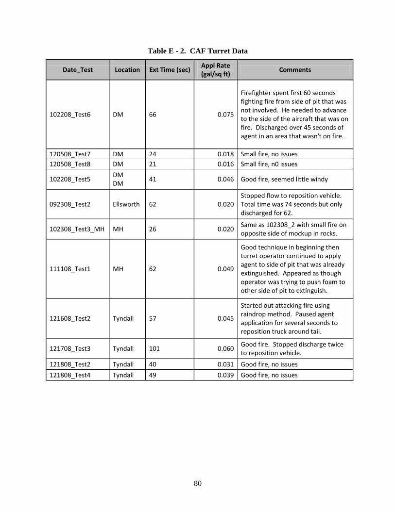
Table E - 2. CAF Turret Data
Date_Test Location Ext Time (sec) Appl Rate (gal/sq ft)
Comments
102208_Test6 DM 66 0.075
Firefighter spent first 60 seconds fighting fire from side of pit that was not involved. He needed to advance to the side of the aircraft that was on fire. Discharged over 45 seconds of agent in an area that wasn't on fire.
120508_Test7 DM 24 0.018 Small fire, no issues
120508_Test8 DM 21 0.016 Small fire, n0 issues
102208_Test5 DM DM
41 0.046 Good fire, seemed little windy
092308_Test2 Ellsworth 62 0.020 Stopped flow to reposition vehicle. Total time was 74 seconds but only discharged for 62.
102308_Test3_MH MH 26 0.020 Same as 102308_2 with small fire on opposite side of mockup in rocks.
111108_Test1 MH 62 0.049
Good technique in beginning then turret operator continued to apply agent to side of pit that was already extinguished. Appeared as though operator was trying to push foam to other side of pit to extinguish.
121608_Test2 Tyndall 57 0.045
Started out attacking fire using raindrop method. Paused agent application for several seconds to reposition truck around tail.
121708_Test3 Tyndall 101 0.060 Good fire. Stopped discharge twice to reposition vehicle.
121808_Test2 Tyndall 40 0.031 Good fire, no issues
121808_Test4 Tyndall 49 0.039 Good fire, no issues
81
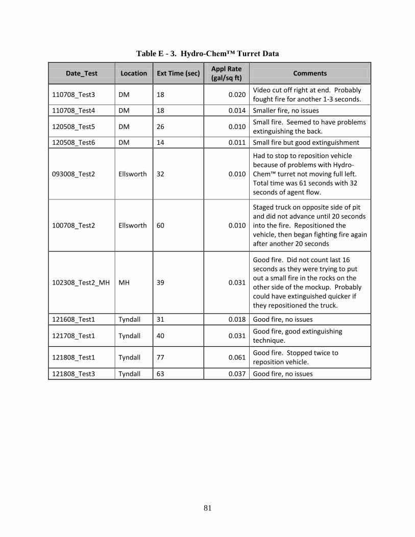
Table E - 3. Hydro-Chem™ Turret Data
Date_Test Location Ext Time (sec) Appl Rate (gal/sq ft)
Comments
110708_Test3 DM 18 0.020 Video cut off right at end. Probably fought fire for another 1-3 seconds.
110708_Test4 DM 18 0.014 Smaller fire, no issues
120508_Test5 DM 26 0.010 Small fire. Seemed to have problems extinguishing the back.
120508_Test6 DM 14 0.011 Small fire but good extinguishment
093008_Test2 Ellsworth 32 0.010
Had to stop to reposition vehicle because of problems with Hydro-Chem™ turret not moving full left. Total time was 61 seconds with 32 seconds of agent flow.
100708_Test2 Ellsworth 60 0.010
Staged truck on opposite side of pit and did not advance until 20 seconds into the fire. Repositioned the vehicle, then began fighting fire again after another 20 seconds
102308_Test2_MH MH 39 0.031
Good fire. Did not count last 16 seconds as they were trying to put out a small fire in the rocks on the other side of the mockup. Probably could have extinguished quicker if they repositioned the truck.
121608_Test1 Tyndall 31 0.018 Good fire, no issues
121708_Test1 Tyndall 40 0.031 Good fire, good extinguishing technique.
121808_Test1 Tyndall 77 0.061 Good fire. Stopped twice to reposition vehicle.
121808_Test3 Tyndall 63 0.037 Good fire, no issues
82
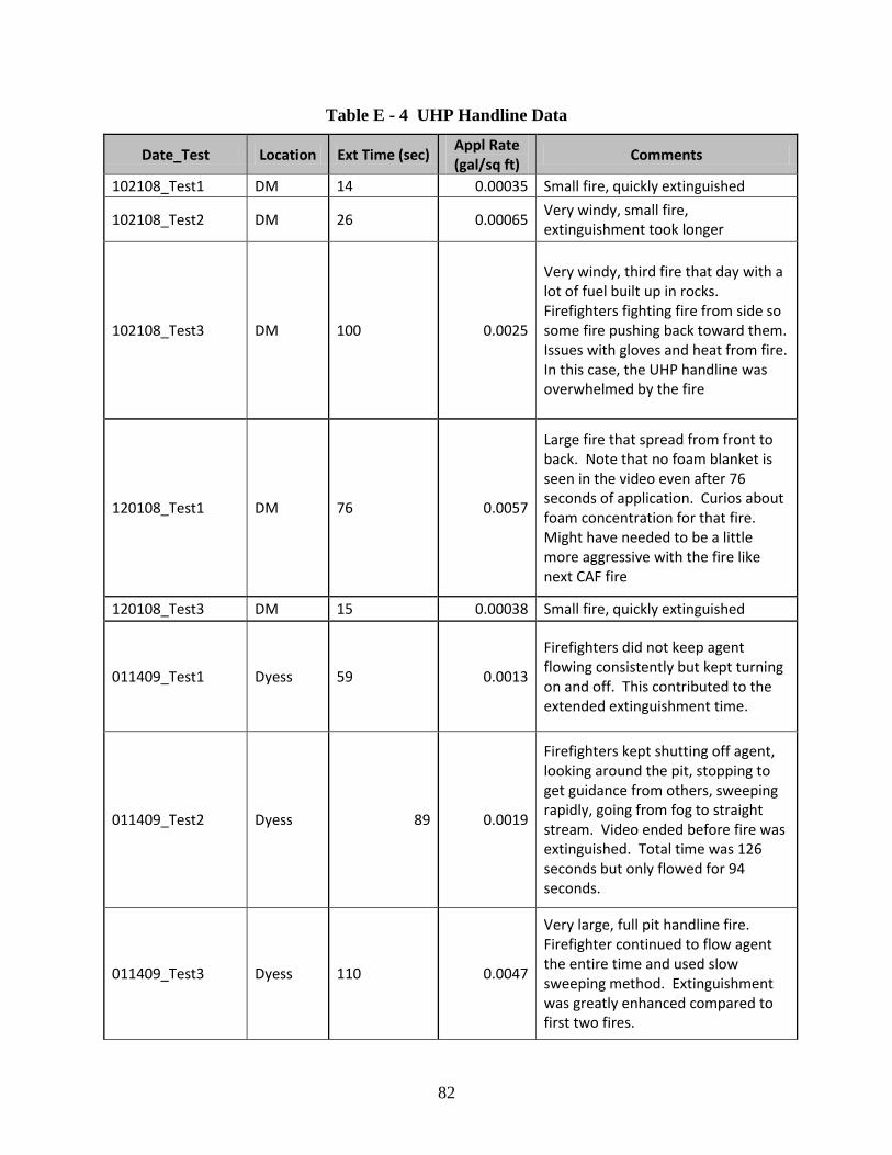
Table E - 4 UHP Handline Data
Date_Test Location Ext Time (sec) Appl Rate (gal/sq ft)
Comments
102108_Test1 DM 14 0.00035 Small fire, quickly extinguished
102108_Test2 DM 26 0.00065 Very windy, small fire, extinguishment took longer
102108_Test3 DM 100 0.0025
Very windy, third fire that day with a lot of fuel built up in rocks. Firefighters fighting fire from side so some fire pushing back toward them. Issues with gloves and heat from fire. In this case, the UHP handline was overwhelmed by the fire
120108_Test1 DM 76 0.0057
Large fire that spread from front to back. Note that no foam blanket is seen in the video even after 76 seconds of application. Curios about foam concentration for that fire. Might have needed to be a little more aggressive with the fire like next CAF fire
120108_Test3 DM 15 0.00038 Small fire, quickly extinguished
011409_Test1 Dyess 59 0.0013
Firefighters did not keep agent flowing consistently but kept turning on and off. This contributed to the extended extinguishment time.
011409_Test2 Dyess 89 0.0019
Firefighters kept shutting off agent, looking around the pit, stopping to get guidance from others, sweeping rapidly, going from fog to straight stream. Video ended before fire was extinguished. Total time was 126 seconds but only flowed for 94 seconds.
011409_Test3 Dyess 110 0.0047
Very large, full pit handline fire. Firefighter continued to flow agent the entire time and used slow sweeping method. Extinguishment was greatly enhanced compared to first two fires.
83
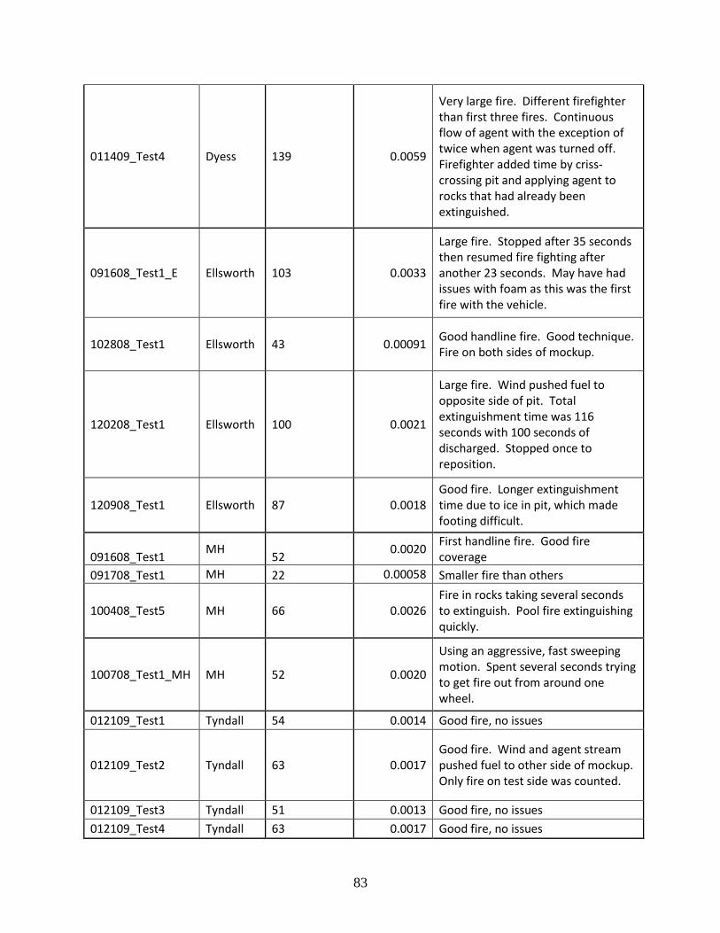
011409_Test4 Dyess 139 0.0059
Very large fire. Different firefighter than first three fires. Continuous flow of agent with the exception of twice when agent was turned off. Firefighter added time by criss-crossing pit and applying agent to rocks that had already been extinguished.
091608_Test1_E Ellsworth 103 0.0033
Large fire. Stopped after 35 seconds then resumed fire fighting after another 23 seconds. May have had issues with foam as this was the first fire with the vehicle.
102808_Test1 Ellsworth 43 0.00091 Good handline fire. Good technique. Fire on both sides of mockup.
120208_Test1 Ellsworth 100 0.0021
Large fire. Wind pushed fuel to opposite side of pit. Total extinguishment time was 116 seconds with 100 seconds of discharged. Stopped once to reposition.
120908_Test1 Ellsworth 87 0.0018 Good fire. Longer extinguishment time due to ice in pit, which made footing difficult.
091608_Test1 MH
52 0.0020
First handline fire. Good fire coverage
091708_Test1 MH 22 0.00058 Smaller fire than others
100408_Test5 MH 66 0.0026 Fire in rocks taking several seconds to extinguish. Pool fire extinguishing quickly.
100708_Test1_MH MH 52 0.0020
Using an aggressive, fast sweeping motion. Spent several seconds trying to get fire out from around one wheel.
012109_Test1 Tyndall 54 0.0014 Good fire, no issues
012109_Test2 Tyndall 63 0.0017 Good fire. Wind and agent stream pushed fuel to other side of mockup. Only fire on test side was counted.
012109_Test3 Tyndall 51 0.0013 Good fire, no issues
012109_Test4 Tyndall 63 0.0017 Good fire, no issues
84
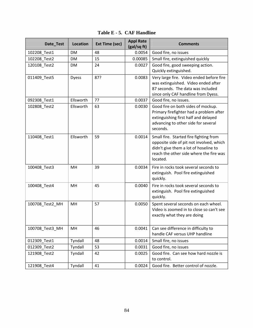
Table E - 5. CAF Handline
Date_Test Location Ext Time (sec) Appl Rate (gal/sq ft)
Comments
102208_Test1 DM 48 0.0054 Good fire, no issues
102208_Test2 DM 15 0.00085 Small fire, extinguished quickly
120108_Test2 DM 24 0.0027 Good fire, good sweeping action. Quickly extinguished.
011409_Test5 Dyess 87? 0.0083 Very large fire. Video ended before fire was extinguished. Video ended after 87 seconds. The data was included since only CAF handline from Dyess.
092308_Test1 Ellsworth 77 0.0037 Good fire, no issues.
102808_Test2 Ellsworth 63 0.0030 Good fire on both sides of mockup. Primary firefighter had a problem after extinguishing first half and delayed advancing to other side for several seconds.
110408_Test1 Ellsworth 59 0.0014 Small fire. Started fire fighting from opposite side of pit not involved, which didn't give them a lot of hoseline to reach the other side where the fire was located.
100408_Test3 MH 39 0.0034 Fire in rocks took several seconds to extinguish. Pool fire extinguished quickly.
100408_Test4 MH 45 0.0040 Fire in rocks took several seconds to extinguish. Pool fire extinguished quickly.
100708_Test2_MH MH 57 0.0050 Spent several seconds on each wheel. Video is zoomed in to close so can't see exactly what they are doing
100708_Test3_MH MH 46 0.0041 Can see difference in difficulty to handle CAF versus UHP handline
012309_Test1 Tyndall 48 0.0014 Small fire, no issues
012309_Test2 Tyndall 53 0.0031 Good fire, no issues
121908_Test2 Tyndall 42 0.0025 Good fire. Can see how hard nozzle is to control.
121908_Test4 Tyndall 41 0.0024 Good fire. Better control of nozzle.
85
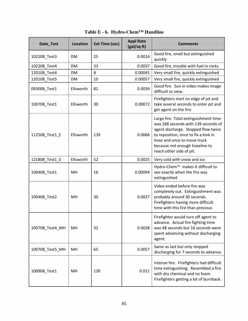
Table E - 6. Hydro-Chem™ Handline
Date_Test Location Ext Time (sec) Appl Rate (gal/sq ft)
Comments
102208_Test3 DM 25 0.0014 Good fire, small but extinguished quickly
102208_Test4 DM 33 0.0037 Good fire, trouble with fuel in rocks
120108_Test4 DM 8 0.00045 Very small fire, quickly extinguished
120108_Test5 DM 10 0.00057 Very small fire, quickly extinguished
093008_Test1 Ellsworth 82 0.0039 Good fire. Sun in video makes image difficult to view.
100708_Test1 Ellsworth 30 0.00072 Firefighters start on edge of pit and take several seconds to enter pit and get agent on the fire
112508_Test1_E Ellsworth 139 0.0066
Large fire. Total extinguishment time was 268 seconds with 139 seconds of agent discharge. Stopped flow twice to reposition, once to fix a kink in hose and once to move truck because not enough hoseline to reach other side of pit.
121808_Test1_E Ellsworth 52 0.0025 Very cold with snow and ice.
100408_Test1 MH 16 0.00094 Hydro-Chem™ makes it difficult to see exactly when the fire was extinguished
100408_Test2 MH 30 0.0027
Video ended before fire was completely out. Extinguishment was probably around 30 seconds. Firefighters having more difficult time with this fire than previous
100708_Test4_MH MH 32 0.0028
Firefighter would turn off agent to advance. Actual fire fighting time was 48 seconds but 16 seconds were spent advancing without discharging agent.
100708_Test5_MH MH 65 0.0057 Same as last but only stopped discharging for 7 seconds to advance.
100908_Test1 MH 130 0.011
Intense fire. Firefighters had difficult time extinguishing. Resembled a fire with dry chemical and no foam. Firefighters getting a lot of burnback.
86
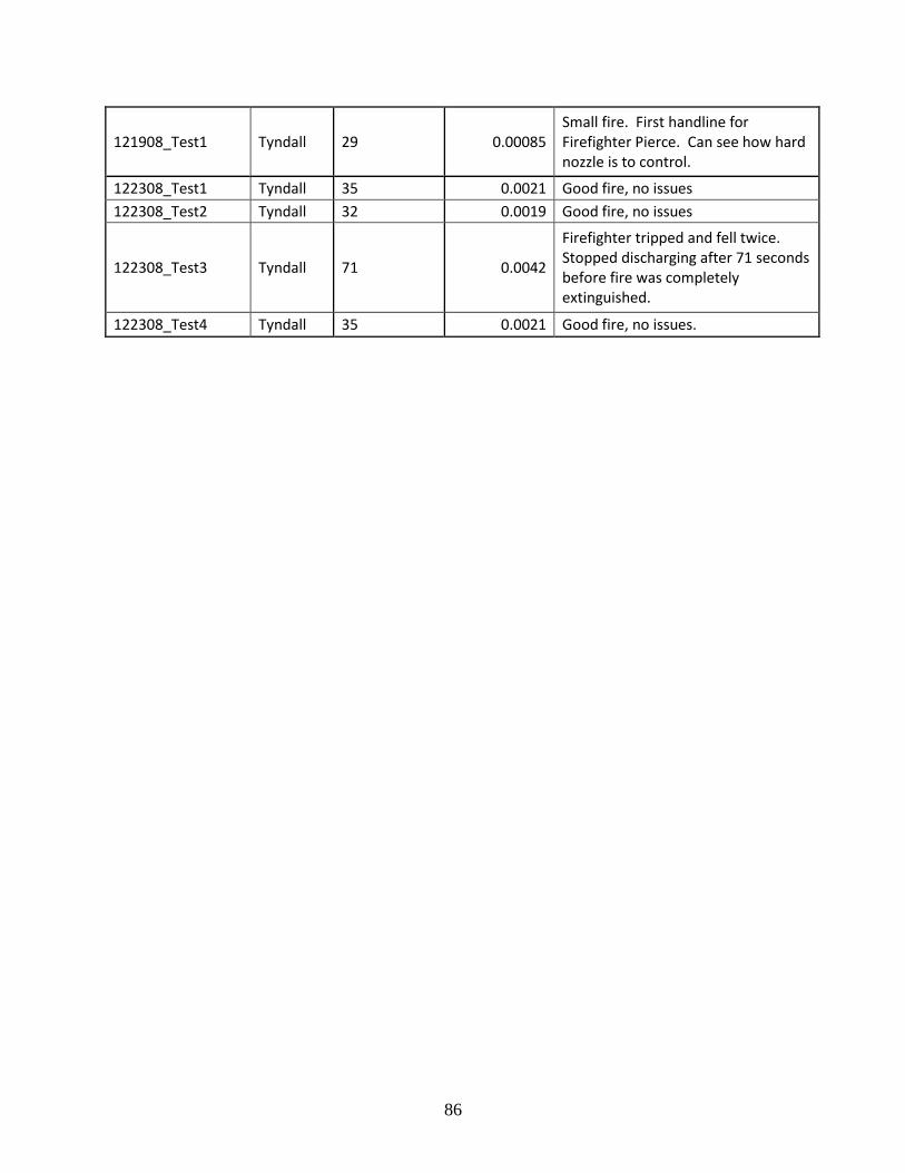
121908_Test1 Tyndall 29 0.00085 Small fire. First handline for Firefighter Pierce. Can see how hard nozzle is to control.
122308_Test1 Tyndall 35 0.0021 Good fire, no issues
122308_Test2 Tyndall 32 0.0019 Good fire, no issues
122308_Test3 Tyndall 71 0.0042
Firefighter tripped and fell twice. Stopped discharging after 71 seconds before fire was completely extinguished.
122308_Test4 Tyndall 35 0.0021 Good fire, no issues.
87
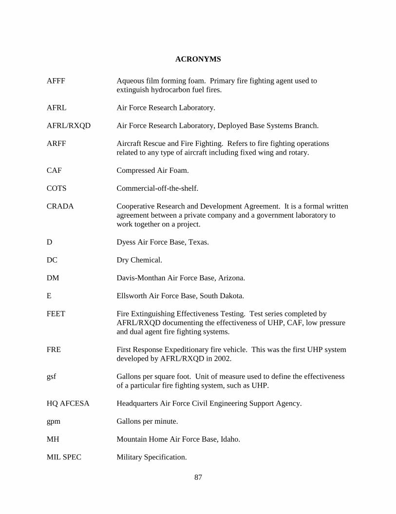
ACRONYMS
AFFF Aqueous film forming foam. Primary fire fighting agent used to
extinguish hydrocarbon fuel fires.
AFRL Air Force Research Laboratory.
AFRL/RXQD Air Force Research Laboratory, Deployed Base Systems Branch.
ARFF Aircraft Rescue and Fire Fighting. Refers to fire fighting operations
related to any type of aircraft including fixed wing and rotary.
CAF Compressed Air Foam.
COTS Commercial-off-the-shelf.
CRADA Cooperative Research and Development Agreement. It is a formal written
agreement between a private company and a government laboratory to
work together on a project.
D Dyess Air Force Base, Texas.
DC Dry Chemical.
DM Davis-Monthan Air Force Base, Arizona.
E Ellsworth Air Force Base, South Dakota.
FEET Fire Extinguishing Effectiveness Testing. Test series completed by
AFRL/RXQD documenting the effectiveness of UHP, CAF, low pressure
and dual agent fire fighting systems.
FRE First Response Expeditionary fire vehicle. This was the first UHP system
developed by AFRL/RXQD in 2002.
gsf Gallons per square foot. Unit of measure used to define the effectiveness
of a particular fire fighting system, such as UHP.
HQ AFCESA Headquarters Air Force Civil Engineering Support Agency.
gpm Gallons per minute.
MH Mountain Home Air Force Base, Idaho.
MIL SPEC Military Specification.
88
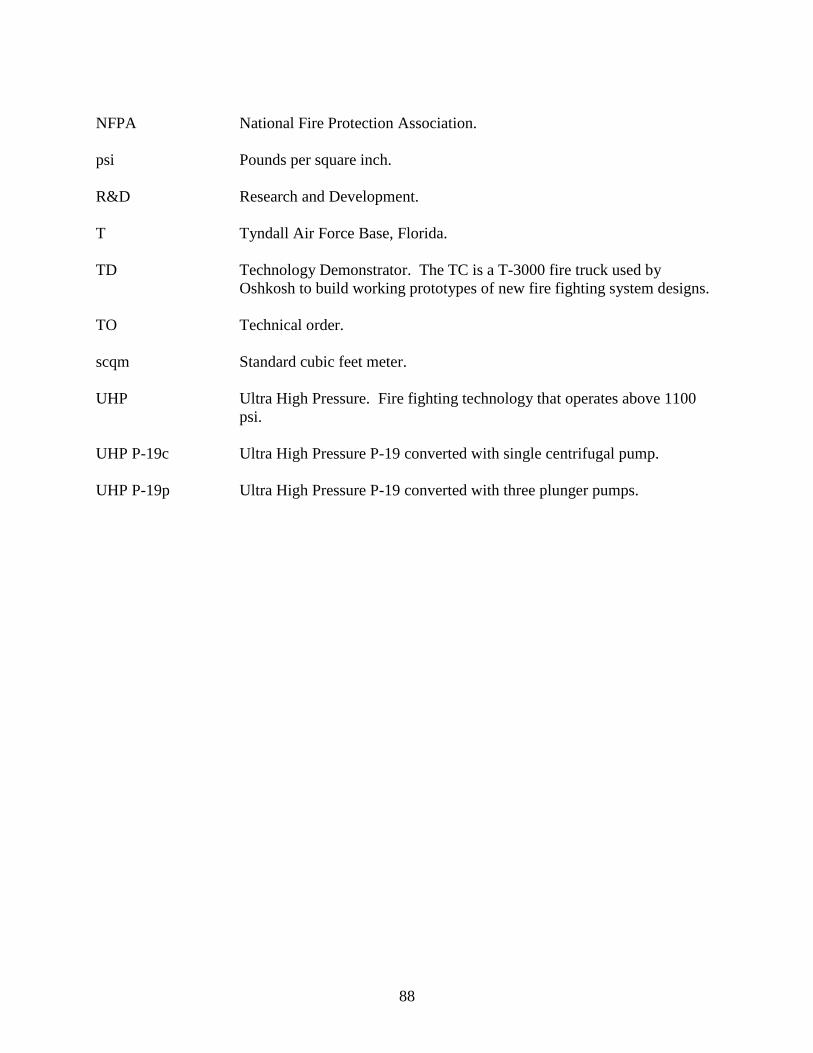
NFPA National Fire Protection Association.
psi Pounds per square inch.
R&D Research and Development.
T Tyndall Air Force Base, Florida.
TD Technology Demonstrator. The TC is a T-3000 fire truck used by
Oshkosh to build working prototypes of new fire fighting system designs.
TO Technical order.
scqm Standard cubic feet meter.
UHP Ultra High Pressure. Fire fighting technology that operates above 1100
psi.
UHP P-19c Ultra High Pressure P-19 converted with single centrifugal pump.
UHP P-19p Ultra High Pressure P-19 converted with three plunger pumps.
89
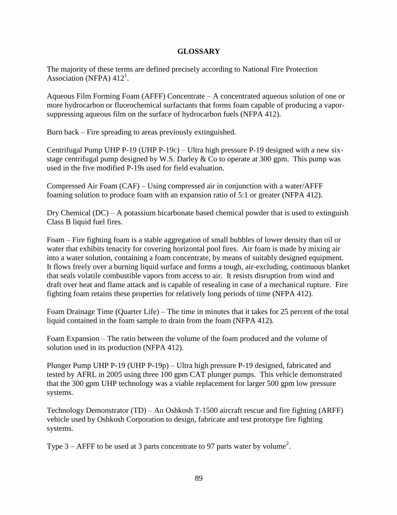
GLOSSARY
The majority of these terms are defined precisely according to National Fire Protection
Association (NFPA) 4121.
Aqueous Film Forming Foam (AFFF) Concentrate – A concentrated aqueous solution of one or
more hydrocarbon or fluorochemical surfactants that forms foam capable of producing a vapor-
suppressing aqueous film on the surface of hydrocarbon fuels (NFPA 412).
Burn back – Fire spreading to areas previously extinguished.
Centrifugal Pump UHP P-19 (UHP P-19c) – Ultra high pressure P-19 designed with a new six-
stage centrifugal pump designed by W.S. Darley & Co to operate at 300 gpm. This pump was
used in the five modified P-19s used for field evaluation.
Compressed Air Foam (CAF) – Using compressed air in conjunction with a water/AFFF
foaming solution to produce foam with an expansion ratio of 5:1 or greater (NFPA 412).
Dry Chemical (DC) – A potassium bicarbonate based chemical powder that is used to extinguish
Class B liquid fuel fires.
Foam – Fire fighting foam is a stable aggregation of small bubbles of lower density than oil or
water that exhibits tenacity for covering horizontal pool fires. Air foam is made by mixing air
into a water solution, containing a foam concentrate, by means of suitably designed equipment.
It flows freely over a burning liquid surface and forms a tough, air-excluding, continuous blanket
that seals volatile combustible vapors from access to air. It resists disruption from wind and
draft over heat and flame attack and is capable of resealing in case of a mechanical rupture. Fire
fighting foam retains these properties for relatively long periods of time (NFPA 412).
Foam Drainage Time (Quarter Life) – The time in minutes that it takes for 25 percent of the total
liquid contained in the foam sample to drain from the foam (NFPA 412).
Foam Expansion – The ratio between the volume of the foam produced and the volume of
solution used in its production (NFPA 412).
Plunger Pump UHP P-19 (UHP P-19p) – Ultra high pressure P-19 designed, fabricated and
tested by AFRL in 2005 using three 100 gpm CAT plunger pumps. This vehicle demonstrated
that the 300 gpm UHP technology was a viable replacement for larger 500 gpm low pressure
systems.
Technology Demonstrator (TD) – An Oshkosh T-1500 aircraft rescue and fire fighting (ARFF)
vehicle used by Oshkosh Corporation to design, fabricate and test prototype fire fighting
systems.
Type 3 – AFFF to be used at 3 parts concentrate to 97 parts water by volume2.
90
Ultra High Pressure (UHP) – Water/AFFF applied at pressures between 1,100-1,500 pounds per