FIELD GUIDE FOR THE IDENTIFICATION AND ASSESSMENT OF LANDSLIDE AND EROSION FEATURES AND HAZARDS Part of a GNS Science Short Course on Landslides and Erosion Hazards Revision 2.1 October 2007 Chris Massey, Graham Hancox and Mike Page GNS Science, Lower Hutt 1 Fairway Drive, Avalon Lower Hutt 5010 New Zealand Tel:+64 4 570 1444 Fax:+64 4 570 4600 PO Box 30368 Lower Hutt 5040 New Zealand
Transcript
FIELD GUIDE FOR THE IDENTIFICATION AND ASSESSMENT OF LANDSLIDE AND
EROSION FEATURES AND HAZARDS
Part of a GNS Science Short Course on Landslides and Erosion Hazards
2.3 Identification of Landslide and Erosion Features .............. 6
2.3.1 Typical Landslide and Erosion Features ................................. 6 2.3.2 Aerial Inspections ................................................................. 13 2.3.3 Ground Inspections ............................................................... 14
2.4 Recording Landslide and Erosion Information................. 15
2.4.1 Plotting locations of landslide features .................................. 15 2.4.2 What to Record ..................................................................... 17
This Field Guide has been prepared by GNS Science as part of a GNS
Short Course on the Identification and Assessment of Landslide and
Erosion Hazards aimed at pipeline overseers and technicians. .
The guide is designed essentially as a reference for pipeline technicians to
use in the field. It contains much of the information presented in the
Landslide Short Course, including: some definitions; a short glossary of
relevant landslide terms; check-box sheets for field observation and
recording of information in the field; a landslide and erosion classification
scheme developed for technicians; and a review of mitigation measures
typically used for landslide and erosion hazards. Some key references for
further reading are also included. The content of the Landslide Short
Course and this Field Guide are intended to provide information that fulfils
and exceeds the requirements set out in the NZQA Unit Standard – Control
erosion and Erosion Planting on pipelines in a petrochemical environment.
1.1 Field Guide Structure and Contents
Initially, the context and purpose of the Field Guide are introduced
(Section 1). The guide then defines landslides and erosion features, and
next focuses on how to identify and record these features in the field from
both aerial and ground reconnaissance (Section 2). The other parts of the
guide deal with landslide classification schemes, including a simplified
scheme for use by technicians (Section 3). The impacts on the pipeline
are then discussed (Section 4) and the different mitigation measures
typically used to stabilise landslide and erosion features are reviewed
(Section 5). Conclusions, along with a proforma, which could be used to
record landslide and erosion features during aerial and field
reconnaissance, are then presented (Section 6).
2. IDENTIFYING AND RECORDING LANDSLIDE AND EROSION HAZARDS
2.1 Some definitions
Short Course -Field Guide 2
GNS Science, Lower Hutt November 2007
(a) Landslide: – Landslides are one type/form of erosion and for the
purposes of this guide are being dealt with separately. A landslide is a
gravitational movement of rock or soil down a slope as a mass along
discrete shear surfaces, owing to failure of the material. Soil includes earth
(material smaller than 2 mm) and debris (material larger than 2 mm). Rock
is a hard or firm intact mass and in its natural place before movement.
Landslides are most often triggered by heavy rainfall or strong
earthquakes, but also occur ‘spontaneously’ without an obvious triggering
event. Such failures are often caused by undercutting slopes by natural
erosion, or slope modification by man, together with long-term weathering
and weakening of slopes. Strong earthquake shaking of Modified Mercalli
(MM) intensity MM7 can cause small failures (<103 m
3), but MM8 or
greater is generally required for larger landslides (≥103–10
6 m
3) –see
Appendix 1.
Landslides are usually classified or described in terms of: (a) the type of
material involved (rock, earth, debris, or sometimes sand, mud etc.), and
(b) the type of movement – fall, topple, slide, flow, spread, which are
distinct modes of movement. Combining these two terms gives a range of
landslide types such as: rock fall, rock slide, rock topple, debris fall, debris
slide, debris flow, earth flow etc. Landslides involving soils and bedrock
are often called slips or landslips, while small failures with rotational slide
surfaces are generally referred to as slumps. Small landslides often do
little damage, but very large failures of thousands or millions of cubic
metres moving downslope can runout and bury buildings and roads, or
cause foundation collapse at the tops of slopes. Effects of landslides can
range from minor deformation of foundations and structural failures to total
destruction of sites and all buildings, lifelines and infrastructure above or
below slopes. General definitions of the main landslide types are shown in
Table 1 and illustrated in Figure 1, and briefly discussed below, these
landslide and erosion types will be discussed in detail in Section 3.
Short Course -Field Guide 3
GNS Science, Lower Hutt November 2007
Table 1 Definitions and characteristics of the main types.
Landslide Type (Based on movement)
General Characteristics (after Cruden and Varnes, 1996)
Falls Falls are masses of rock, soil, or debris that move rapidly down very steep slopes (>40°) by free fall, bounding or rolling. Disrupted soil and debris falls most common.
Slides Slides are masses of rock, soil, or debris that slide down planes of weakness (bedding, joints, faults) and other surfaces. Rotational slides (or slumps) in soft rocks and soils move on curved failure surfaces. Disrupted soil and debris slides are most common. Landslides are also referred to (non-specifically) as slips, landslips, or slippages.
Avalanches Rock and debris avalanches are very rapid, long run-out failures on steep slopes (>35-40°) more than 150-200 m high. They may start as falls or slides, and transform into flows (wet or dry). Occur mainly on hill country and high mountain slopes.
Debris Floods and
Debris Flows
Debris floods are rapid hyper-concentrated flows in streams, of water charged with sediment, often coarse gravel and sand. Debris flows are a type of landslide: they have much higher sediment concentrations (like wet concrete) than debris floods, and are potentially much more hazardous and destructive. Objects impacted by debris floods are surrounded or buried by gravel, but are often largely undamaged.
Figure 1 Main types of landslides (generalised after Varnes, 1978).
Short Course -Field Guide 4
GNS Science, Lower Hutt November 2007
Debris flows and debris floods: These are both hydrological mass-transport
phenomena but have different hazard and risk implications. Debris floods
are rapid hyper-concentrated flows in stream channels of water charged
with sediment. Debris flows are a type of landslide: they have higher
sediment concentrations than debris floods, with a consistency rather like
wet concrete. Debris flows have the ability to transport large boulders, and
are therefore potentially much more hazardous and destructive. A debris
flood is not a landslide and is less hazardous, with destructiveness similar
to that of water, but less than debris flows; both generally occur on alluvial
fans. Objects impacted by debris floods are surrounded or buried by flood
debris but are often largely undamaged (Hancox, 2003), as seen during
the 2003 Paekakariki storm (Figure 2).
Figure 2 Debris flood gravels buried buildings and cars at this motel during a
rainstorm at Paekakariki in 2003, but caused little serious damage to the buildings (the cars were written off however).
(b) Erosion: – Erosion is a term referring to those processes of denudation
which wear away the land by the mechanical actions of erosional agents
such as rivers, streams, waves on the shores of the sea and lakes,
glaciers, and wind. The process of erosion thus involves transportation of
Short Course -Field Guide 5
GNS Science, Lower Hutt November 2007
soil and rock debris by the various agents, and must be distinguished from
(chemical) weathering, in which no transportation is involved. Gravity is
regarded as a prime factor in erosional processes, along with abrasion and
corrosion (the mechanical erosion of a rock surface by material (debris)
being transported across it by streams, rivers, glaciers, waves, and wind.
Landsliding (gravitational downslope mass movements) is therefore a
significant erosional process.
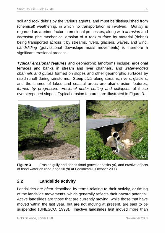
Typical erosional features and geomorphic landforms include: erosional
terraces and banks in stream and river channels, and water-eroded
channels and gullies formed on slopes and other geomorphic surfaces by
rapid runoff during rainstorms. Steep cliffs along streams, rivers, glaciers,
and the shores of lakes and coastal areas are also erosion features,
formed by progressive erosional under cutting and collapses of these
oversteepened slopes. Typical erosion features are illustrated in Figure 3.
Figure 3 Erosion gully and debris flood gravel deposits (a), and erosive effects of flood water on road-edge fill (b) at Paekakariki, October 2003.
2.2 Landslide activity
Landslides are often described by terms relating to their activity, or timing
of the landslide movements, which generally reflects their hazard potential.
Active landslides are those that are currently moving, while those that have
moved within the last year, but are not moving at present, are said to be
suspended (UNESCO, 1993). Inactive landslides last moved more than
( a) ( b )
Short Course -Field Guide 6
GNS Science, Lower Hutt November 2007
one year ago, and are currently not moving. Inactive landslides are
subdivided into: Dormant – the causes of (and potential for) movement
remain. Stabilised– remedial measures have stopped landslide movement.
Relict– landslides that developed under different geomorphological or
climatic conditions, and may be several hundreds or thousands of years
old (prehistoric, see Figures 4 and 9). A landslide that has been inactive
but has started to move again is called reactivated.
Figure 4 Very large (~30 million m3) relict landslide near Martinborough.
Several thousand years old, its main scarp (MS) is eroded, and its toe (lt)
trimmed by the river when the terrace (t) was formed >1,000 years ago.
Landslide ponds (p), an active earth flow (efl) with hummocky ground, and
shallow soil slides (sl) formed on the main scarp in February 2004, both
superficial reactivations on the slide mass, are also apparent.
2.3 Identification of Landslide and Erosion Features
2.3.1 Typical Landslide and Erosion Features
Landslides have geomorphic features that make them identifiable as mass
movement landforms. Typical landslide features and their internationally-
recognised names are shown in Figure 5, which are unchanged from
M S
M S
p
p
p
e f l
s l
s l
s l
Short Course -Field Guide 7
GNS Science, Lower Hutt November 2007
Varne’s original classification (1978), apart from the addition of some minor
features (landslide pond, hummocky ground, springs, and seeps). These
features are important as their recognition makes it possible to identify
landslides, from aerial and ground inspections. Important landslide
features, their significance, and some simple ways to recognise both active
and inactive landslides, and erosion features are summarised in Table 2
and Figure 5.
Figure 5 Block diagram of an idealised complex rotational earth slide and
earth flow showing typical landslide features (after Varnes 1978). ‘Real life’ examples of similar landslides are shown in Figures 6, 8, and 9.
Short Course -Field Guide 8
GNS Science, Lower Hutt November 2007
Table 2 Landslide features and criteria for field recognition.
Landslide Features Description of features
Active landslides (and recently active or dormant landslides)
Landslide scar Includes the source area and debris trail.
Source area The area at the head of the landslide (zone of depletion) where the landslide mass (debris) is derived from.
Landslide debris Material (rock, soil, vegetation) displaced from the source area and transported down-slope by gravity.
Main scarp The main scarp is the steep slope in undisturbed ground at the head of the slide (head scarp) – the visible part of the failure surface. Minor (secondary) scarps may be present within the displaced material of the landslide mass
Tension cracks Often located upslope of the landslide main scarp and tend to be aligned in an arc, and can be continuous or discontinuous, but are essentially linear. These indicate horizontal (pull-apart) movement, but may also show vertical and shear movement.
Hummocky ground Ground surface irregular, often formed of low amplitude hummocks, resulting from differential (compressional and shear) deformations within the displaced material – a feature of many landslides (active and inactive).
Ponds (un-drained) Ponds formed in depressions, which are often un-drained, are present within the displaced material of many landslides, especially at the slide head; they may be filled by seepage from springs, or by rainfall.
Springs, seepages Give rise to areas of swampy or boggy ground; seepage water may accumulate in ponds.
Trees with curved trunks or leaning backwards
Wind, steep topography and ground movement can all give rise to non-vertical tree trunks, so care is required in their interpretation so additional supporting evidence of landslide movement is required.
Notes: Relative positions of features referred to in this table are shown in Figure 5. Actual examples of some of the landslide illustrated in Figures 4, 6, 8 and 9. (Table 2 contd. next page)
Short Course -Field Guide 9
GNS Science, Lower Hutt November 2007
Table 2 - Landslide features and criteria for field recognition (contd.).
Landslide Features Description of features
Disruption of natural drainage
May be seen directly or inferred from seepages. Also, where landslide debris may have totally/partially blocked a drainage line, or where the drainage line has been forced to alter its course.
Cracking to structures and paved surfaces and dislocation of drainage structures
These can also be related to local settlement of fill and foundations, so additional supporting evidence is required, e.g. presence of a source areas/landslide debris, tension cracks, trees leaning backwards
Relict landslides (inactive old landslides with little potential for reactivation)
Relict landslides typically have eroded, rounded and subdued features, with no sharp features or bare scarps visible. The main scarp is generally eroded and well vegetated. The displaced landslide mass often has ponds and hummocky and irregular ground. Generally, no cracks or indications of movement are visible. Trees and established vegetation show no evidence of tilting, non-vertical trunks, or disturbance
Notes: Relative positions of features referred to in this table are shown in Figure 5. Examples of some of the landslide illustrated in Figures 4, 6, and 7.
Typical erosion features and geomorphic landforms include: erosional
river terraces, river/stream banks and bed, and water-eroded rills and
gullies formed on slopes and other geomorphic surfaces by rapid runoff
during rainstorms. Steep cliffs along streams, rivers, glaciers, and the
shores of lakes and coastal areas are also erosion features, formed by
progressive erosional under cutting and collapses of these over-steepened
slopes. Typical erosion features are illustrated in Figure 3.
Short Course -Field Guide 10
GNS Science, Lower Hutt November 2007
Figure 6 This large, recently active rotational slide in mudstone formed a small
landslide-dammed lake in the Whangaehu valley in February 2004. Other earth slides and flows formed at the same are also visible.
Areas of bare ground including planar/disk-shaped paddocks, unsealed
roads and tracks, areas of heavy stock concentration, landslide scars and
landslide debris trails are all prone to sheet erosion. If sheet erosion is left
unchecked rills can develop, and once established, rills can develop into
gullies and ultimately landslides and washouts. Different erosion processes
and their impacts are discussed in more detail in Sections 3 and 4.
Figure 7 This typical erosion
gully at Paekakariki was formed in periglacial gravel deposits in the valley head during the October 2003 rainstorm. No such features had formed in the area in the last 150 years (since the native bush was cleared), which suggests that the rainfall (c. >125 mm in 4 hours) during the storm was exceptional.
Short Course -Field Guide 11
GNS Science, Lower Hutt November 2007
Figure 8 Oblique aerial photo of the large (c.5,000 m3), rotational slide (sl) and
earthflow in mudstone, which threatened several houses (H1, H2) in Hunterville in July 2006. The landslide, which formed on the headscarp of a ‘relict’ (prehistoric) landslide, is c. 75 m wide and 3–12 m deep at its head (left). It transformed into a slow-moving earthflow, which extended c. 265 m down a gentle slope towards the houses. Other features seen here are: tension cracks around the slide head (tc); shallow soil (earth) slides formed during the Feb. 2004 storm; old landslide debris (ols); and a bund (b) and channel (c) to direct further debris and protect the houses.
Figure 8 shows that the July 2006 (active landslide) has fresh, sharply
defined features (scarps, cracks debris) that are devoid of vegetation. In
sharp contrast, the ‘relict landslide’ feature has typically rounded and
subdued features; although the former headscarp (main scarp) and
mounds of old landslide debris are still clearly recognisable. In this
example, the active (2006) landslide could also be described as
reactivated because it has formed on the former main scarp of the relict
landslide.
Landslide Short Course -Field Guide 12
GNS Science, Lower Hutt November 2007
Figure 9 Multiple shallow earth slides and a large rotational slide (s l ) and earth flows occurred in the Mangawhero valley
during the February 2004 rainstorm. The large (>c.100 million m3) prehistoric ‘relict’ landslide (r s l ) opposite, with its vegetated,
hummocky topography and landslide ponds (p) was apparently unaffected by the storm.
r s l
p s l
Short Course -Field Guide 13
GNS Science, Lower Hutt November 2007
The typical landslide features described above can be used to identify the
existence of landslides. The next two sections explain how this should be
done on aerial and ground inspections, along with the benefits of both
approaches.
2.3.2 Aerial Inspections
Aerial reconnaissance using either helicopter or fixed-wing aircraft provides
an efficient means to inspect long sections of pipeline. The latter is
cheaper and can fly faster, but is not as good for accurate observation.
Fixed wing aircraft usually fly at higher altitude, which not only affects the
quality of the observations, but also any photos and video shots taken on
the flight. Helicopters are more expensive, but are much better for
observing landslide and erosion effects as they can fly slowly along and a
few hundred metres above pipelines, hovering over critical areas for close
observation and photography. As well as routine inspections, aerial
inspections should also be carried out following severe rainstorms/flooding
events and high magnitude earthquakes.
For clarity, and to avoid reflections, photographs should be taken with the
door open, or it should be taken off before the flight. If possible, always
observe and take photographs looking away from the sun, so flight
directions should be planned with this in mind. Sunny days are better than
overcast days, as the greater contrast and shadows present on sunny days
make landslide features stand out more clearly. Avoid aerial inspections
and photography in the rain, which reduces visibility and safety.
Accurate locations of pipeline observations and photographs are critical during
aerial inspections. Topographic maps (1:50,000) or pipeline route maps allow
good locations to be obtained, as do hand-held GPS units. Some cameras (for
example the Nikon D200) allow photographs to be linked to a GPS unit, with grid
references added to meta file data for photographs taken on a flight. Photographs
taken using normal digital cameras can also be linked to grid references using
GPS-photo link software. This works by linking the date and time of the hand held
GPS unit to the date and time of the camera (usually by photographing the screen
of the GPS with the camera). The software then links the time stamp of the photos
Short Course -Field Guide 14
GNS Science, Lower Hutt November 2007
to the time stamp in the GPS track log. Any new landslide features that affect the
pipeline, or have the potential to affect or damage the pipeline, should be
photographed and noted for future ground inspection. On future flights photos
should be taken from a similar distance and direction to monitor any changes in the
size and activity of the feature.
2.3.3 Ground Inspections
Ground inspections are also used by technicians to inspect sections of
pipeline route, especially in areas where erosion or landslide features were
observed on aerial inspections. Ground inspections are often carried out
during fine weather, or when a storm has passed. There is also, however,
value in inspecting pipeline sites during bad weather. Although this may be
difficult, and possibly hazardous, because of flooding and track wash-outs,
it does allow direct observation of the erosional effects of rapid runoff on
slopes, streams, and rivers in the vicinity of the pipeline. If sites of known
landslides and erosion features cannot be inspected during a storm, they
should be inspected as soon as the weather clears to determine the effects
of the storm, and especially to observe and record any changes in the
known features in relation to the pipeline.
The main activities and data collected during a typical ground inspection
may include:
Precisely locate new landslide or erosion features, or changes in old
features, on topographic or pipeline route maps, or by GPS.
Inspect and take photos of any known features from various angles.
Take both close-up and distant photos, and if possible from sites used
to take previous photos. Photos should show the slopes above and
below the pipeline, as well as the areas immediately adjacent to the
pipeline.
Map the extent of the features using GPS, tape measure, or by pacing
out the features. Draw a rough sketch of the features and annotate
with brief descriptive notes.
Note the nature of the materials present in the area (e.g. silt, clay,
sand, gravel, cobbles/boulders or rock) and strength (soft, strong, very
strong etc).
Short Course -Field Guide 15
GNS Science, Lower Hutt November 2007
Note areas of water seepage and ponding and whether the materials
are dry, moist or wet.
Note any changes in stream flows in the area near the pipeline, and
any changes in erosive effects.
Details and methods of recording and plotting landslide and erosion
information obtained during pipeline inspections is described in greater
detail in the next section.
2.4 Recording Landslide and Erosion Information
2.4.1 Plotting locations of landslide features
Landslide and erosion features can be plotted on:
(a) Published topographic maps (1:50,000);
(b) Pipeline route maps (based on Topomaps);
(c) Vertical aerial photos;
(d) Oblique aerial photos (taken on aerial inspections);
(e) GPS (NZMG coordinates).
Figures 10a-c show examples of a topographic map and vertical and
oblique aerial photos in relation to a gas pipeline.
Short Course -Field Guide 16
GNS Science, Lower Hutt November 2007
Figure 10a Topographic map (1:50,000) showing pipeline near Paekakariki at the
Ohariu Fault crossing, where the pipeline is above ground on ‘skids’ to allow for future fault movement. The fault crossing is more clearly shown on vertical and oblique aerial photos (see Figures 10b and 10c).
Figure 10b Vertical aerial photo of a gas pipeline (p) where it crosses aFault (F).
Although the pipeline at this site is located on a ridge, and is not particularly exposed to landslides, an erosion gully (eg), formed in October 2003 below the pipeline to the east, could possibly affect it in the future.
( a)
( b )
p
e g
F
Short Course -Field Guide 17
GNS Science, Lower Hutt November 2007
Figure 10c Oblique aerial photo of a gas pipeline (p) where it crosses a fault (F).
2.4.2 What to Record
A variety of information should be recorded by technicians on any landslide
and erosion features that are impacting, or could impact the pipeline. The
main points that should be recorded are described briefly below.
(a) Topographic location: The positions of all landslide and erosion
features in the immediate vicinity (within c.10-20 m) of the pipeline should
be recorded, especially landslides upslope of the pipeline, or gullies and
drainage features that cross it. Locations of features should be marked on
a sketch map and GPS locations used where possible.
(b) Site details: Site details that should be recorded include:
Position on slope (upper, middle, lower).
Slope steepness (measure or estimate slope angle),
Distance from pipeline, streams, rivers, tracks etc.
Nature of slope above features and pipeline
(c) Size of landslide and erosion features:
From the air the size of any landslide and erosion features can be
p
( c )
F
Short Course -Field Guide 18
GNS Science, Lower Hutt November 2007
estimated in relation to the pipeline dimensions, or the size of
known features such as access tracks, roads, farm gates etc.
On the ground the size of any features should be measured using
GPS (also records location), tape measure, or by pacing (a last
resort, but better than nothing). Record vertical limits (height
difference) across feature (m), and also estimate the slope or
gradient (i.e. the horizontal distance (m) for 1 m vertical rise) in two
or three locations above and below the pipeline.
(d) Material type:
The nature of the materials present in and around the feature
should be recorded and their locations marked on the sketch map.
The strength and moisture conditions of the materials should also
be noted using the details contained in Section 3.3.
(e) Activity:
The current activity and rates of movement of landslide features
should be estimated (use terms outlined above). Note whether the
feature is currently active and is still moving, or shows signs of
recent movement, or signs of the potential for possible future
movements or slope failures (such as ground cracking above the
landslide scar or failure scarp, stream erosion at toe etc.).
(f) Potential for Future Activity:
Consider (your best guess) what might happen to the landslide or
erosion feature in the future, based on the visible features (and
using the information contained in Appendix 4). Provide
photographic or sketch record of the evidence.
(g) Photographic Record:
It is always valuable to record and show the location of features.
Use both aerial and ground photos.
Aerial photos: Take close up (high resolution, at least 5 mega pixel)
photos of the entire feature, and also more distant shots showing
the pipeline and terrain above and below the feature and pipeline.
Record the date and time (digital photos make this easy); repeat
photo from the same height and angle on future inspections; take
several photo over several weeks or months to monitor feature.
Ground photos: Use the same approach as for aerial photos. Take
Short Course -Field Guide 19
GNS Science, Lower Hutt November 2007
a series of shots to show details of the feature at its most active
location, and also shots showing its position relative to the pipeline.
Repeat photos on subsequent inspections.
This information should be recorded using the proforma contained in
Appendix 2 (Pipeline Threat Investigation proforma). A sketch map
showing the fey features identified on site should also be produced using
the symbols contained in Appendix 3.
3. CLASSIFICATION SCHEMES
3.1 Landslides
When carrying out a landslide assessment for a pipeline or other key
network it is usual to establish a series of landslide-hazard models, which
best describe the landslides that either have occurred or could occur along
the alignment. Landslide-hazard models are landslides that have been
grouped together on the basis of:
Material type – nature of the displaced material – rock, debris or earth
Type of movement – how the debris from the landslide is transported
e.g. by falling, toppling, rolling and bouncing, sliding, flowing or as a
combination, e.g. a slide that develops into a flow etc.
Additional descriptions can also be used regarding: topographical location
– where the landslide is located on the slope e.g. open slope (where the
landslide and debris remains totally on the open hillside and is not
channelised along a stream course), or channelised (where the landslide
debris is channelised along a stream course); and velocity of the debris –
extremely rapid (typical velocity 5m/second) to extremely slow (typically
>16mm/year).
These different descriptions are combined to then classify the landslide.
Many different types of landslide have been defined and these are shown
in Table 3, which summarises the main landslide hazards.
Landslide Short Course -Field Guide 20
GNS Science, Lower Hutt November 2007
Table 3 Classification of landslide type after Varnes, 1978, DoE., 1990 and BGS, 1999.
Landslide Short Course -Field Guide 21
GNS Science, Lower Hutt November 2007
Table 3 Continued
Landslide Short Course -Field Guide 22
GNS Science, Lower Hutt November 2007
Table 3 Continued
Landslide Short Course -Field Guide 23
GNS Science, Lower Hutt November 2007
Table 3 shows that there are many different types of landslide hazard,
which although important, are difficult to identify in the field and many are
in fact variations on a theme.
For the purpose of this course the landslide hazards contained in Table 3
have been simplified into those landslides, which predominantly occur in
New Zealand and more importantly, occur along the pipeline alignment. It
is recommended that when trying to classify landslides the following main
hazard types are used, the details of which are presented in Table 4.
Table 4 Landslide hazard types typically encountered in New Zealand along
pipeline alignments.
Hazard type Description
FLOWS These types of hazard usually originate as shallow slides, however, the failed mass tends to break down, becoming saturated and remoulded to move as a flow.
1) Open slope – FLOW
These types of hazard are slow to rapid (typically 3 m/minute to 13 m/year), with the debris remaining wholly on the open hillside and not channelised along a stream course.
2) Channelised – FLOW
These types of hazard are rapid to extremely rapid (typically 5m/second to 3m/minute), with the debris becoming channelised along a stream course. Channelised debris flows generally have much greater mobility than open slope flows, and normally develop when debris from one or more landslides enters a stream course, and becomes mixed with stream water. Deposition of the debris tends to occur once it reaches low angle open slopes, forming debris fans.
3) SLIDES
(deep-seated)
Movement of an intact mass by sliding along a basal rupture surface. These types of hazard are generally slower moving (1.6 m/year to 16 mm/year) and have deeper rupture (slip) surfaces than the type of shallow
Landslide Short Course -Field Guide 24
GNS Science, Lower Hutt November 2007
Hazard type Description
slides that lead to flow-type landslides. The displaced material tends to move along the surface of rupture as a series of discrete intact blocks (these types of landslide are often referred to as translational block-slides).
4) ROCK FALLS/TOPPLES
This type of hazard results from one or more rock fragments being transported initially by free-falling but may include sliding, rolling and bouncing.
It is relatively straightforward to identify these different landslide hazard
types in the field as each type has a series of distinctive features, which
relate specifically to that type.
3.1.1 Open slope flows
Open slope flows (shown schematically in Figure 11) are landslides where
the debris stays unconfined, remaining on the open-slope. As the
landslide debris remains unconfined the runout (defined as the distance
from the landslide crown to the toe of the debris) tends to be limited, due
to frictional drag, as the debris is allowed to spread out over the ground
surface.
These landslides tend to originate as slides, with the debris breaking
down and mixing with water to become a slurry (flow). Blocks or rafts of
intact material tend to be transported on this slurry. The Hunterville
landslide (Figure 8, Section 2.3) is one such example of an open slope
flow. Debris from this landslide was recorded moving at a velocity of 80m
over 30 minutes (0.04 m/sec).
Landslide Short Course -Field Guide 25
GNS Science, Lower Hutt November 2007
Figure 11 Schematic diagram of an open slope flow
3.1.2 Channelised flows
Channelised flows (as shown schematically in Figure 12) are landslides
where the debris becomes confined (channelised) along a stream course.
As the landslide debris is confined runout of the debris tends to be
significant, as it mixes and becomes diluted with additional water from
along stream course.
These landslides also tend to originate as slides and could be in part open
slope flows, before being channelised. These types of landslide are
extremely rapid and can runout over several kilometres, and so the source
area could be located some distance away from where the debris
eventually stops.
Landslide Short Course -Field Guide 26
GNS Science, Lower Hutt November 2007
Figure 12 Schematic diagram of a channelised flow
As a result, these types of landslide tend to cause the most deaths world
wide. The Eastbourne landslide, Wellington (Figure 13) is one such
example of a small channelised flow. Debris from this landslide was
recorded moving at a velocity of approximately 12 m/sec).
Landslide Short Course -Field Guide 27
GNS Science, Lower Hutt November 2007
Figure 13 Aerial view of two channelised flows at Eastbourne, which closed
the road and damaged two houses at the bottom of the stream course. The channelised flows originated as shallow slides in an area of recently milled pine forest (visible at the top of the photograph) some distance upslope from the affected road and houses.
3.1.3 Slides
Slides (as shown schematically in Figure 14) are landslides where the
failed material remains as a series of intact blocks (or rafts), which slide
along a basal rupture surface (slip plane). These landslides tend to pose
the greatest hazard to road, rail and pipeline networks as they are
relatively large and deep-seated, requiring detailed investigations and
costly designs to mitigate against. These landslides should be avoided if
possible.
Landslide Short Course -Field Guide 28
GNS Science, Lower Hutt November 2007
Figure 14 Schematic diagram of a slide.
These types of landslide are typically slow, and only tend to affect the
infrastructure located on or within the sliding mass. The Waikorora Bluff
slide (Figure 15), located at the northern end of the Whitecliffs State
Forest is a good example of a slide. At this location an approximate 400m
length of pipeline passes around the head and lateral margins of an active
slide.
Landslide Short Course -Field Guide 29
GNS Science, Lower Hutt November 2007
Figure 15 Oblique aerial photograph of the Waikorora Bluff slide
Landslide Short Course -Field Guide 30
GNS Science, Lower Hutt November 2007
3.1.4 Rockfalls
Rockfalls (as shown schematically in Figure 16) are hazards associated
with steep cliffs, and usually involve either individual rock blocks, or
multiple rock blocks (avalanche), which free fall, bounce, roll and slide
down slope. These hazards are extremely rapid and can involve small to
large volumes of material.
Figure 16 Schematic diagram of a rockfall
3.2 Erosion
Other main forms of erosion which affect pipelines and associated
infrastructure (e.g. access roads to and from the pipeline) are described in
the Table 5. The defining aspects of each of these processes are
highlighted in bold italics.
Landslide Short Course -Field Guide 31
GNS Science, Lower Hutt November 2007
Table 5 Erosion hazards typically encountered along gas pipe alignments in
New Zealand.
Erosion type Description
Sheet erosion The removal of surface material by non-channelised overland flow of water.
Rills Typically less than 50cm deep and less than 100cm wide, near linear features, which occur either on their own or as multiple features. They are features that can be smoothed out/removed by cultivation using normal farm equipment. Rills typically develop as sheet erosion becomes more established.
Gullies Unlike rills, these are large permanent features that cannot be removed using normal farm equipment. Like rills, gullies are formed by the channelised flow of water, including headword migration of the channel. Gullies tend to develop once rills become established.
Stream bank and stream bed erosion
Stream bank and bed erosion refers to the removal of material from the banks and bed of a stream during periods of high water flows
Wind erosion Refers to the removal and transportation of particles (soil, sediment etc) by wind action.
Coastal cliff erosion
Coastal cliffs and escarpments (not necessarily located on the coast) can retreat (erode backwards) due to removal of material from the slope toe (for coastal cliffs caused by wave action) and exposed (bare) slope surfaces (through rock falls, rills, gullies etc).
Tunnel gullies (aka: pipe; shaft erosion, tomos, under runners)
Caused by the subsurface flow and concentration of water, resulting in the removal of material by water, forming narrow conduits, tunnels, voids or pipes.
Deposition of sediment/debris
Deposition refers to sediment (including vegetation) that has been eroded, transported and deposited by running water. This material may be deposited in channels, on terrace surfaces by overbanking of streams or rivers, or on fans (possibly deposited by landslide processes and not just water).
Landslide Short Course -Field Guide 32
GNS Science, Lower Hutt November 2007
Descriptions and photographic examples of the different types of erosion
discussed in Table 5 are contained in the following sections.
3.2.1 Sheet erosion, rills and gullies
Sheet erosion is caused by a combination of raindrop impact dislodging
fine soil particles, and overland flow, which transports the soil particles
away. Where overland flow concentrates and where the velocity of the
flow increases, rills may develop. Rills can develop into gullies as a result
of ongoing incision and headword migration caused by cutting down due
to concentrated flow of water. The main difference between rills and
gullies are that rills can usually be removed by farm machinery, while
gullies cannot.
Figure 17 Photograph showing the development of rills on a de-vegetated
slope.
Landslide Short Course -Field Guide 33
GNS Science, Lower Hutt November 2007
3.2.2 Stream bank and bed erosion
Stream bank and bed erosion is caused by the flow of water along a
stream or other water course. Mechanisms of erosion include bed and
bank scour, which removes support and leads to the toppling of the bank.
For stream bank erosion this generally occurs on the falling stage of a
flood event, when the strength of the material forming the bank is
decreased due to uptake of water from the river and the support of the
river is removed, while stream bed erosion is most severe during peak
flows (e.g. associated with storm events).
Figure 18 Photograph showing stream bank erosion due to undercutting and
scour of the bank by water flowing along the stream course (Awakino River).
Landslide Short Course -Field Guide 34
GNS Science, Lower Hutt November 2007
Figure 19 Photographs showing the change in river course before (A) and
after (B) a storm event, as a result of bed erosion. Note where material from the river bed has been eroded and new material deposited.
A
A
B
Landslide Short Course -Field Guide 35
GNS Science, Lower Hutt November 2007
3.2.3 Tunnel gullies
Tunnel gullies form in weathered or weak materials where subsurface
water concentrates above a relatively impermeable layer (e.g. landslide
debris overlying rock). Land susceptible to tunnel gully erosion includes
moderately steep hill country where soft materials such as loess and
tephra deposits (volcanic materials) overlie stronger sandstones and
mudstones.
Figure 20 Photograph of a tunnel gully, which resulted in failure of the entire
road carriageway.
Like tunnel gullies, sinkholes (also known as a sink, shake hole, swallow
hole, swallet, doline or cenote) are natural depressions or holes in the
surface topography. Sinkholes may vary in size from less than a meter to
several hundred meters both in diameter and depth and can form
gradually or rapidly. Mechanisms of formation typically include: gradual
Figure 23 Aerial photograph of the Twin creeks area (North Taranaki), note
the actively retreating sea cliffs, caves and arches. A pipeline follows the crest of these cliffs, and because of ongoing erosion, was realigned using horizontal directional drilling technology.
3.3 Material types
In most cases, it is the nature of the material, whether soil, rock or man
made fill, which usually controls the susceptibility of the ground to erosion.
Recording material properties in the field is essential to understanding the
nature of the problem. Although many variations in materials exist, there
are two essential and relatively straightforward properties that should be
recorded: material type; and material strength. By using the details
contained in Tables 6a and 6b it should be possible to classify the
different materials in the field, based on a few simple observations and
tests.
Landslide Short Course -Field Guide 39
GNS Science, Lower Hutt November 2007
Table 6a Material type descriptions
Material Type Description
Organic (peat) Contains much organic vegetable matter; often has
noticeable smell and changes colour on oxidation.
Clay Grain size < 0.002mm, not visible to eye. Plastic
(cohesive), sticks to the fingers and dries slowly;
shrinks appreciably on drying, usually showing
cracks.
Silt Grain size 0.06 to 0.002 mm, not visible to eye.
Dilatant; slightly granular or silky to the touch;
disintegrates in water, lumps dry quickly; can be
plastic but can be powdered between fingers.
Sand 2 to 0.06 mm, grains visible to the eye. Contains
little or no cohesion; grading can be described, well-
grade or poorly-graded.
Gravel 60 to 2 mm. Shape and grading can be described
Cobbles/boulders > 60 mm. Shape and grading can be described
Rock (include type
e.g. greywacke etc)
Describe rock: strength; colour; texture; and name if
possible; also include a description on weathering
Table 6b Material strength descriptions
Strength Description
Soil – sands, gravels and boulders
Loose Obvious Voids between grains
Dense No obvious voids between grains
Soil – clays, silts and organics
Very soft Exudes between fingers
Soft Moulded by light finger pressure
Firm Moulded by strong finger pressure
Stiff Cannot be moulded by finger pressure
Rock
Weak Easily crumbled by hand
Landslide Short Course -Field Guide 40
GNS Science, Lower Hutt November 2007
Strength Description
Moderately weak Broken with difficulty in two hands
Strong Firm blows with point of pick causes only superficial
damage
Very strong Many hammer blows required to break specimen
In addition to material properties, the moisture content of a material
should also be recorded (e.g. dry, moist and wet), as soft wet materials
tend to be more prone to erosion than dry materials.
4. HAZARDS AND THEIR IMPACTS
This section looks at the possible impacts each of the main hazard types
discussed in Section 3 could have on the pipeline alignment. Impacts to
the pipeline alignment (or access roads) from most types of erosion
hazard will depend upon the topographic position of the feature with
respect to the at-risk facility.
4.1 Open slope flows
If the landslide source area is located upslope of the pipeline it is possible
that debris from the landslide may runout and impact the pipeline. Open
slope flows do not tend to runout long distances and in most cases (if the
landslide is relatively small) may have little impact on the pipeline itself.
However, debris from the flow may block access along the pipeline. If the
landslide is of significant size and debris (several meters in thickness)
were to be deposited on top of the pipeline, then this could place
additional load on to the pipeline. In this situation the debris should be
removed and if deemed necessary pipeline integrity should be checked.
If the source area is located down slope of the pipeline it is unlikely that
debris from the landslide will have any effect. However, the source area
may undercut the pipeline and in the worst case this could lead to the
pipeline being exposed. It is also possible that a source area located
Landslide Short Course -Field Guide 41
GNS Science, Lower Hutt November 2007
immediately down slope of the pipeline could retrogress (erode
backwards) undercutting the pipeline. Figure 24 shows the main hazards
associated with open slope flows.
Figure 24 Schematic diagram showing the hazards (1 and 2) associated with
open slope flows.
Hazard 1 – Slide movement in the landslide source area could cause the
pipe to shear at the flanks of the landslide, or undercut the pipeline if
located above the main scarp.
Hazard 2 – Debris sourcing from open slope flows on the steep slope
could deposit material on top of the pipeline, placing additional load on the
pipe.
Landslide Short Course -Field Guide 42
GNS Science, Lower Hutt November 2007
4.2 Channelised flows
Unlike open slope flows, debris from channelised flows can travel long
distances. If the debris remains channelised along the stream course it
can cause significant erosion. Some channelised flows may have only
small source areas, but can bulk to many times their original size due to
erosion and entrainment (inclusion) of additional material from along the
stream course. Debris from these types of landslide tends to deposit if:
the debris overtops the stream course (becoming non-channelised); or
when the channel flattens out. If the latter occurs the debris typically
forms distinctive fan-like features. A catchment prone to debris flows
usually has a distinctive debris fan located at its mouth. When assessing
the hazard from channelised flows it is important to look further-a-field
(than for open slope flows and slides) at entire drainage catchments
rather than individual slopes. If the pipeline crosses a potential debris-
flow path it is important to assess whether the crossing is located at a
channelised or fan section of the stream course
For CHANNELISED sections (where the debris is channelised along a
stream course) the pipeline is at greatest risk. Channelised flows are high
in energy and can easily scour, expose and damage buried pipelines. At
aerial pipeline crossings it is also possible that debris could impact the
pipeline if the debris overtops the channel. Figure 25 shows the main
hazards associated with channelised flows.
Landslide Short Course -Field Guide 43
GNS Science, Lower Hutt November 2007
Figure 25 Schematic diagram showing the hazards (1 and 2) associated with
for the pipeline to be scoured (buried crossing) or impacted (aerial
crossing).
Hazard 2 – Potential exists for future debris flows to either scour out the
pipeline or place additional load on top of the pipeline.
4.3 Slides
These landslides tend to pose the greatest risk to pipelines as they are
often misidentified or assumed to be inactive. In most cases the slip
plane usually corresponds to a change in material type or zone of
weakness. Many of the slides observed in the hill country around
Taihape, Wanganui and New Plymouth have slip planes which
Landslide Short Course -Field Guide 44
GNS Science, Lower Hutt November 2007
correspond to the boundary between weathered soil and rock
(mudstone/siltstone) and tend to be relatively shallow (slip plane <5 m
below ground surface). In most cases open slope and channelised flows
originate as slides. Other types of slide, e.g. the Waikorora slide (Figure
15, Section 3.1.3) have slip planes that are relatively deep (>10 m below
ground surface), which correspond to weak zones (clay seams) within the
rock. Figure 26 shows the main hazards associated with slides.
Figure 26 Schematic diagram showing the hazards (1 and 2) associated with
slides.
Hazard 1 – Retrogressive failure (eroding backwards) of the landslide
main scarp could undercut the pipeline. Evidence of potential
retrogression is shown by the presence of tension cracks (located upslope
from the main scarp).
Landslide Short Course -Field Guide 45
GNS Science, Lower Hutt November 2007
Hazard 2 – As the pipeline is within the sliding mass, shear forces can
develop on the pipe at the flanks of the landslide, leading to deformation
or even rupture of the pipe.
4.4 Rock falls
Rockfalls are triggered by earthquakes and more frequently by periods of
high rainfall and frost shattering (in areas of extreme cold). Areas
particularly at risk from rockfalls are those located at the toe of steep
slopes, e.g. coastal cliffs etc. Coastal cliffs are particularly vulnerable to
rockfalls as they are constantly being eroded by wave action, leading to
retrogression (eroding backwards) of the cliff top. Figure 27 shows the
main hazards associated with rockfalls.
Figure 27 Schematic diagram showing the hazards (1 and 2) associated with
rockfalls.
Hazard 1 – Continued erosion of the steep cliff by either: sea erosion (if
Landslide Short Course -Field Guide 46
GNS Science, Lower Hutt November 2007
forming a sea cliff, e.g. Tongaporutu, North Taranaki); rainfall; and even
earthquakes, could lead to undercutting of the pipe as a result of cliff-line
regression.
Hazard 2 – If the pipeline is located along the toe of an actively eroding
cliff (evidence in the form of scree/talus or boulders at the toe of the
slope), it could be susceptible to impact loading from rockfalls.
4.5 Erosion
4.5.1 Sheet, rill and gully erosion
Sheet, rill and gully erosion can lead to undercutting and exposure of the
pipeline. Once established, rills and gullies can incise and enlarge
relatively quickly and in some cases lead to the development of
landslides.
4.5.2 Stream bank and bed erosion
At river crossings and where the pipeline alignment is adjacent to
rivers/streams, it is extremely vulnerable to stream bank and bed erosion.
The banks of active stream courses are prone to collapse as a result of
undercutting by stream bank erosion, therefore where the pipeline
alignment is located next to a stream/river course, bank collapse could
lead to undercutting of the pipeline (Figure 28). Stable stream banks can
be made unstable by changes in the stream course. For example a tree
stump washed downstream (at times of peak flow) can form a constriction
(at times of low flow), leading to concentrated erosion and stream bank
collapse (Figure29).
Materials forming the bed of a river are constantly being eroded,
redistributed and deposited, and during periods of peak flow (during
storms), streams and rivers can laterally migrate, often altering their
courses. Bed erosion can result in exposure of the pipeline where it
crosses a river. If the pipeline is exposed it becomes vulnerable to impact
by material being transported by the river. Figure 30 shows the main
erosion hazards and their potential impact on the pipeline.
Landslide Short Course -Field Guide 47
GNS Science, Lower Hutt November 2007
Figure 28 Photograph showing erosion on the outside bend of a meander,
possibly caused by deposition of debris into the main river channel from a smaller stream, leading to the development of a bar, which has in turn caused undercutting and collapse of the stream bank (Awakino River).
Figure 29 Photograph showing stream bank erosion initiated by the deposition
of a tree stump (Araheke Stream).
Landslide Short Course -Field Guide 48
GNS Science, Lower Hutt November 2007
In addition to stream bank and bed erosion, old river terraces (areas of flat
ground adjacent to large streams and rivers) can form a hazard to the
pipeline. These terraces are usually formed of soft, organic, clays and
silts, which are highly compressible. If these soils are loaded by e.g.
landslide debris, fill material, or over-bank deposits from flooding of the
river, the increased load can lead to differential settlement, and ultimately
to deformation of the pipeline. Old river terraces are usually easy to
identify, as they tend to be located next to large rivers, are flat, with
hummocky surfaces and ponded water apparent.
Figure 30 Schematic diagram showing the hazards (1 and 2) associated with
stream bank erosion.
Hazard 1 – Stream bank erosion and incision can cause bank collapse
leading to undercutting of the pipeline. Stream bank and bed erosion can
also remove cover material from the pipeline, leaving it exposed at the
surface and vulnerable to impact from boulders and vegetation washed
down the stream/river.
Landslide Short Course -Field Guide 49
GNS Science, Lower Hutt November 2007
Hazard 2 – Gully erosion on stream banks (especially where smaller
streams and gullies join the main river), can lead to undercutting of the
pipeline, and failure of the banks.
4.5.3 Wind erosion
Wind erosion usually develops when surface vegetation covering old sand
dunes is removed (by farming practices or excavations). High winds
associated with coastal areas transport material away from bare exposed
areas, and over time and if left un-managed, can lead to exposure of the
pipeline.
Figure 31 Pipeline exposed in an old sand dune, due to ongoing removal of
sand by wind erosion.
4.5.4 Coastal erosion
Coastal erosion caused by wave action can lead to cliff retreat. The rate
of cliff retreat depends upon several factors, but is mainly controlled by
Landslide Short Course -Field Guide 50
GNS Science, Lower Hutt November 2007
the nature (strength) of the materials forming the cliff, and presence of
dominant geological structures (e.g. faults and joints). In areas where the
pipeline is located along the top of actively retreating sea cliffs, it can be
vulnerable to severe undercutting, especially in locations where it
traverses across dominant geological structures, as these areas tend to
erode more readily.
Figure 32 Coastal cliff erosion at Tongaporutu, North Taranaki. A pipeline passes
behind the crest of the actively eroding cliffs. Rates of sea cliff regression are relatively high in this area where the material comprises weak, siltstones and sandstones.
4.6 Other hazards and indicators of potential hazards
As well as landslide and erosion hazards, other potential hazards along
the pipeline alignment that should be assessed are listed in Table 7.
Landslide Short Course -Field Guide 51
GNS Science, Lower Hutt November 2007
Table 7 Other potential hazards affecting the pipeline.
No. Potential Hazard Description
Ground vulnerable to landslides
1 Steeply sloping ground in colluvium (typically
>25 in angle)
Typically slope angles >25 in colluvium (old landslide debris) tend to be unstable and if possible these slopes should be identified and routinely inspected. Things to look for when identifying these features are: presence of relict landslide features; hummocky ground; ponding of water; and tension cracks (see table 2 for detailed descriptions).
2 Slopes where water can be seen to collect and/or seeping
Slopes usually fail as a result of locally high groundwater levels. Therefore areas of sloping ground which appear to have seepages, springs or ponded water on them, could be either large relict slides, or ground susceptible to future failure.
3 Slopes formed in adverse geological structures and materials (e.g. the Tertiary materials of North Island NZ.
Certain material types are more prone to landslides and erosion, due to the properties of the materials, mainly: strength; and composition (clay, silt, sand etc). For example the Tertiary sediments, (through which a large section of the Maui pipeline traverses), are low strength materials formed of sand and silt, which are prone to wide-scale landslides.
4 Slopes adjacent to active fault zones
Geological faults cause materials to become sheared and fragmented, usually leading to the material having a lower strength and therefore more prone to landslides.
5 Slopes likely to be prone to river or stream scour at their base
Undercutting of slopes by rivers/stream courses can cause the slopes to become over-steep, and unstable. This process can also lead to reactivation of old relict landslides, as material from the landslide toe is removed.
6 Sheet Erosion
(including areas of rilling/gullying)
Bare surfaces such as: paddocks; unsealed roads and tracks; areas of heavy stock concentration; landslide scars; and landslide debris trails. Once sheet erosion becomes established it can lead to the development of rills and gullies. Therefore once identified it should be addressed immediately.
7 Areas devoid of vegetation
Including areas of recently felled forest (also refer to number 10).
8 Stream banks As number 10.
9 Landslide flow-paths
Landslides tend to leave scars on the hillside due to removal of vegetation. As a result, the bare ground is prone to erosion, which can lead to further landsliding.
Landslide Short Course -Field Guide 52
GNS Science, Lower Hutt November 2007
No. Potential Hazard Description
Human interference
10 Slopes modified by man, e.g. slope over steepening, undercutting of toe and removal of vegetation.
Steep man-made cuts are prone to landslides, as slope cutting either leads to the over-steepening or undercutting of slopes. If not done correctly this can lead to landslides. Removal of vegetation can also lead to shallow landslides, as vegetation intercepts rainwater and the roots tend to hold the near surface materials together, increasing their strength. It should be noted that vegetation has little stabilising effect on large deep-seated slides, as the slip planes tend to be below the depth of root penetration.
11 Excavations along the pipeline alignment (unrelated to slope modifications)
Unauthorised excavations along the pipeline right of way can lead to exposure and damage to the pipeline. It is assumed that there are procedures in place to deal with these types of issues. Current code requirements state that there must be a minimum of 800 mm of cover.
12 Placement of fill along the pipeline alignment
Placement of fill material (or any other material) on top of the pipeline increases the vertical earth load acting on the pipeline. This is primarily a consideration for non-operating conditions of buried steel pipelines (when the pipeline is under no internal pressure). Under most operating conditions, the external earth pressures are insignificant in comparison to the internal pipe pressures. Vertical earth load is an important consideration when designing pipe casings used for rail and road crossings. Placement of additional load onto the pipeline can lead to settlement of the ground and deformation of the pipe. Areas susceptible to settlement tend to be soft (saturated) ground (e.g. river flood plains and old terraces, valley bottoms and areas of landslide debris).
13 Creation of unauthorised access routes across the pipeline alignment
In addition to supporting dead loads imposed by earth cover, buried pipelines can also be exposed to superimposed concentrated or distributed live loads. Large concentrated loads such as those caused by truck-wheel loads can place additional load onto the pipe and if the pipeline has not been designed to take these loads (in the case of unauthorised access routes over the pipeline) problems could occur.
It is assumed that a procedure is in place to deal with unauthorised access across buried pipelines.
14 Changes in land use
Removal of vegetation (as numbers 6 and 8), changes in farming practices and water course deviations caused by man could all impact the pipeline by changing the local conditions making some areas more prone to landslides/erosion.
Landslide Short Course -Field Guide 53
GNS Science, Lower Hutt November 2007
4.7 Hazard assessment
Figure 33a is a schematic diagram showing how the different hazards
discussed in this section interact in the landscape. Typically an
assessment of the hazards along the pipeline alignment is carried out
prior to route selection and construction. The purpose of this assessment
is to identify the locations of the different hazards so that mitigation
measures can be designed and constructed to safeguard the pipeline,
Figure 33b. The main tasks which form a typical hazard assessment are
discussed in detail in Section 5.2.
The hazards discussed in this section relate to those hazards more
frequently encountered along the pipeline. This discussion does not
include hazards such as earthquakes, Tsunami, flooding and volcanic
eruptions, as well as any health and safety hazards (as detailed in the
Health and Safety in Employment Act 1992).
4.7.1 Site assessment
A site assessment form (contained in Appendix 4) has been created to
assess the severity (threat) a particular hazard may have on the pipeline.
This form brings together the information contained in Sections 2, 3 and 4
to allow the hazard (threat) type and risk to the pipeline to be determined.
The risks have been classified into three categories:
Low – No risk to the pipeline at present or in the future (years) – hazard
assessed as inactive
Intermediate – No immediate risk to the pipeline, however, ongoing
development of the hazard could impact the pipeline in the future
(months) – hazard assessed as active.
High – High risk to pipeline, where the pipeline has been exposed at the
ground surface, or where the hazard is highly active and will lead to failure
of the pipe.
Landslide Short Course -Field Guide 54
GNS Science, Lower Hutt November 2007
Figure 33a Schematic diagram showing the different landslide and erosion hazards discussed in Section 4.
Landslide Short Course -Field Guide 55
GNS Science, Lower Hutt November 2007
Figure 33b Schematic diagram showing the impacts from the different hazards shown in Figure 26a.
1 Aerial crossing over river – potential for streambank erosion and impact from channelised flows
2 Pipeline at toe of steep cliff, with rock fall debris on surface – potential for rockfalls.
3 Pipeline traverses debris fan – potential for burial or scour by channelised flows.
4 Pipeline traverses the main scarp of an active landslide with tension cracks visible on surface – potential for the landslide main scarp to retrogress, undercutting the pipeline.
5 Pipeline passes near the head of actively incising erosion gully – potential that the gully could retrogress, exposing the pipe.
6 Pipeline traverses the toe of a steep slope, with evidence of historic open slope flows – potential for the debris from future open slope flows impacting and burying
the pipe.
Landslide Short Course -Field Guide 56
GNS Science, Lower Hutt November 2007
5. MITIGATION MEASURES
Landslide and erosion mitigation measures should ideally be designed on
a site specific nature by an engineering geologist/geotechnical engineer.
However, there are several prescriptive techniques which could be used
to maintain the pipeline ROW and limit the severity of the
landslides/erosion hazards.
This section will look at the approaches typically adopted by engineering
geologists/geotechnical engineers when designing landslide/erosion
mitigation measures. This section will also include some prescriptive
designs, which could be adopted to either limit or protect the pipeline or
other areas of critical infrastructure related to the pipeline (e.g. access
roads etc) form landslide /erosion hazards.
5.1 Stabilisation techniques
Four main approaches are typically used for the design of soil/rock slopes,
landslide and erosion mitigation measures, these are: 1) avoid the
problem; 2) reduce the driving forces; 3) increase stabilising forces by
application of an external load; and 4) increase stabilising forces by
increasing the internal strength. These approaches can be used either
individually or in combination depending on the nature of the particular
hazard. The effectiveness of these measures also depends upon the
material forming the slopes, as some techniques are best applied to soil
slopes while others are specifically for rock slopes.
Table 8, provides comments on the applications and limitations of the four
main approaches for stabilising landslides, slopes and reducing the
effects of erosion.
Landslide Short Course -Field Guide 57
GNS Science, Lower Hutt November 2007
Table 8 Typical mitigation techniques
Approach Technique Discussion
Avoid Problem
Realign pipeline HIGH COST; could create similar problems; slow to implement.
Completely or partially remove unstable material
Moderate cost; only feasible for shallow, small slips; could create further instability
Construct structures to prevent debris from impacting the pipeline
HIGH COST; slow to implement; must be capable of containing debris
Reduce driving forces
Re-grade slope Unlikely to be feasible in steep terrain; requires earthworks to remove overburden/rock blocks, which can be costly.
Will prevent surface water from infiltrating, but need to be combined with other measures e.g. bioengineering, spring tapping etc.
Drain subsurface (sub-soil drains)
Should be used as cut off-drains to prevent near-surface water from entering landslide; or at the landslide/slope toe to promote drainage of water from wet areas.
Increase stabilising forces by application of an external load
Construction of retaining walls/buttresses
Moderate cost to HIGH COST; walls must be founded beneath slip plane; buttresses should be keyed into rock slope with dowels. These should be combined with other techniques.
Construct shear key at toe
Requires large working area at toe of landslide.
Install anchors HIGH COST, only used for rock slopes; specialist installation equipment and ongoing monitoring required.
increase stabilising forces by increasing the internal strength
Drain sub-surface (sub-soil drains)
If the slip plane is deep then sub-soil drains can have little effect as water needs to be removed from near the slip plane.
Soil nails HIGH COST, typically only used for soil slopes that have not failed; specialist installation equipment and ongoing monitoring required.
bioengineering Not suitable for steep slopes and deep-seated slides. Vegetation type is critical.
Landslide Short Course -Field Guide 58
GNS Science, Lower Hutt November 2007
5.2 Hazard assessments
When assessing what stabilisation measure(s), are applicable to a
particular hazard type the engineering geologist/Geotechnical engineer
usually carries out a detailed investigation and hazard assessment, which
includes some or all of the following tasks:
Desk study (review of all existing information, at both the regional
and site-specific scales), including: geology and geomorphology
maps, aerial photographs; results from any previous investigations;
rainfall records etc.
Field Mapping (to field verify the findings from the desk study),
including: site-specific geology and geomorphology, material index
testing etc.
Ground investigation (to quantify the materials and conditions on
site, e.g. depth to slip plane, groundwater conditions etc; and to
collect samples for laboratory testing), including: drilling of boreholes,
excavation inspection trenches, in situ testing, geophysics etc.
Laboratory testing (to determined the strength characteristics of the
materials derived from the ground investigation)
Analyses (to analyse the information collated from the desk study,
field mapping, ground investigation and laboratory testing stages), this
may include: setting up critical cross sections through the
slope/landslide; numerical stability analysis; identification of
movement triggering factors (in the case of landslides)
Design: the findings from the hazard assessment are then used to
determine the most appropriate mitigation strategy.
5.2.1 Case Study –landslide
Detailed investigations were carried out for th landslide, Figure 15,
Section 3.1.3. In 1994 the movement rate of the landslide increased
rapidly and so a detailed assessment of the landslide was undertaken to
design the most appropriate mitigation measures. The assessment
and design of mitigation measure, comprising: 1) removal of material from
Landslide Short Course -Field Guide 59
GNS Science, Lower Hutt November 2007
the main scarp of the landslide (to reduce the driving forces); 2) re-
directing of the stream course away from the landslide (again to reduce
the driving forces); and 3) installation of sub-soil drains (to increase the
stabilising forces by increasing the internal strength of the landslide
debris).
Figure 34 shows the movement history of several markers installed on the
surface of the landslide. From 1981 to 1996 the movement rate of the
landslide was up to 1.5 m/year. Following installation of the mitigation
measures this movement rate dropped to approximately 0.003 m/year,
indicating that the mitigation measures were working.
Figure 34 Graph showing the cumulative movement (displacement) of the
landslide. The movement of several marker installed on the landslide has been plotted against rainfall patterns to determine the links between movement and rainfall.
Landslide Short Course -Field Guide 60
GNS Science, Lower Hutt November 2007
The landslide is a large, deep-seated slide and is a very complex
landslide, requiring a detailed hazard assessment by suitably qualified
people. Other smaller landslides or areas suffering from erosion may not
require such detailed analysis and design. The following sections discuss
some prescriptive mitigation measures which could be used l to reduce
the impacts of such hazards on the pipeline and associated infrastructure.
5.3 Design measures (landslides, slopes and erosion)
Typically any design measures used for landslide and erosion hazards fall
Some of the more common techniques for treating rock slopes are
illustrated in Figure 35a, 35b and 35c. These techniques mainly
comprise: rock slope reinforcement; rock fall control; rock removal. The
majority of these techniques require detailed design by an engineering
geologist/geotechnical engineer. Some techniques such as creating rock
catch ditches (at the toe of steep rock slopes) can be done without
detailed design and could prevent rock falls from impacting the pipeline.
Landslide Short Course -Field Guide 61
GNS Science, Lower Hutt November 2007
Figure 35a and 35b Rock slope control and reinforcement methods
commonly used for rock slopes.
Figure 35c Rock slope control – removal of potentially unstable rock blocks.
Landslide Short Course -Field Guide 62
GNS Science, Lower Hutt November 2007
For soil slopes there are a range of retaining walls available. These are
illustrated schematically in Figure 36. For most types of retaining wall,
detailed design is required by an engineering geologist/geotechnical
engineer. In some cases, however, it could be possible to install
gabion/concrete block retaining walls without detailed design, if: the wall is
temporary (to prevent ongoing deterioration prior to a detailed
investigation); the size of the wall is relatively small; (i.e. <1.5 m high); and
if the asset is low risk (i.e. access road). Gabion (bolster) walls (typically
one row of gabions installed as a line on a slope/landslide) are particularly
useful as they allow water to pass through them, acting like large drains,
as well as trapping sediment, therefore preventing rill and gully
development. Gabion walls can also accommodate settlement and
movement without being compromised, while pile walls and crib walls
cannot take even minor movements without cracking and failing.
Figure 36 Typical retaining wall design details
Landslide Short Course -Field Guide 63
GNS Science, Lower Hutt November 2007
5.3.2 Earthworks
Earthworks to stabilise slopes/landslides typically comprise: the regrading
(cutting back) of the slope to a more stable angle; removal of overburden
(to reduce the driving forces) and creation of a shear key at the toe of the
slope (to increase the stabilising forces). In most cases, debris from a
landslide (depending upon the size of the landslide) should be removed
from the landslide source area, to prevent it from re-mobilising in
response to rainfall.
Earthworks tend to be costly and require planning, permits and consents
to be obtained. Disposal of spoil can also pose a serious issue, as
placing spoiled material on terrain susceptible to landslides/erosion could
accelerate these processes and in some cases lead to the development of
landslides on originally stable ground. Placement of spoil should be in a
stable area: on level ground; in dry valleys; on the tops of spurs; at
locations protected by bedrock; as far away from the pipeline and stream
courses as possible and where property or public safety are not affected).
Bare slopes (whether newly formed cut slopes or spoil slopes) are prone
to erosion once exposed to the elements. Any bare slopes should have
erosion protection measures installed on them soon after formation.
These may comprise drainage and/or bioengineering measures. To
prevent erosion in spoil areas it is also preferable to compact the spoil
material and re-vegetate therefore increasing the material strength of the
spoil.
5.3.3 Drainage
Drainage control is critical to the stability of slopes. Uncontrolled runoff
can create major erosion problems within very short periods of time.
Slope drainage as described in Table 9, can often result in a marked
improvement in the stability of a slope.
Landslide Short Course -Field Guide 64
GNS Science, Lower Hutt November 2007
Table 9 Typical drainage details commonly used for landslides and erosion
control.
Function Type Description Hazard Type/Location Used
Interception of surface runoff
Unlined cut-off drain
Shallow trench used to intercept surface water, preventing sheet erosion, rills and gullies from developing. Can also be used to prevent water from entering landslides.
All landslide hazard types and areas prone to sheet erosion including constructed slopes. Typically installed upslope of landslide main scarps or at the crest of newly formed slopes. The prevent water from entering the landslide, debris or slope. May create line of instability beyond crest; may be prone to erosion.
Lined cut-off drain.
Same as above but lined with concrete, masonry or plastic.
Same as above, but Less prone to erosion and leakage Requires frequent inspection for damage/blockage.
Interception of high/perched water table.
Herringbone drain.
Able to intercept water up to a max of approx. 1.5m depth below surface; good for intercepting surface seepage of springs and point sources of water; can accommodate some slope movement.
All landslide hazard types and areas prone to sheet erosion including constructed slopes. Typically installed in the landslide source area, newly formed slopes, or active landslide debris. May only have limited effect on slope stability for deep-seated slides as the drains do not intercept deep groundwater.
Counterfort drain. Able to intercept water up to approx. 3m depth below slope face.
Slides and constructed slopes Typically used to drain the toe and debris of active slides or potentially unstable slopes. They can act as a shear key if founded below landslide slip plane. Difficult to construct in bouldery material.
Interception of deep water table.
Horizontal/subsoil drains.
Only feasible method of intercepting deep groundwater. Should be installed
Deep-seated slides Highly effective in stabilising deep-seated slides provided they can be constructed to an adequate depth. Moderately
Landslide Short Course -Field Guide 65
GNS Science, Lower Hutt November 2007
Function Type Description Hazard Type/Location Used
in the landslide debris, with the base just above the slip plane.
costly requires drilling rig (horizontal drain) or excavator with shield for subsoil drains; may not always work.
Diversion or improvement of stream course/gully.
Lined channel or cascade.
May be necessary if existing stream course is direct cause of instability.
All landslide hazard types and areas prone to sheet erosion including constructed slopes Anywhere where water from the stream course is thought to be the main driving force for instability/erosion. Usually very expensive and difficult to construct and can result in moving the problem elsewhere.
Erosion control in gully/stream course.
Check dam. Relatively cheap, removes energy (erosion potential) from water.
Streambank erosion Good for stream courses affected by channelised flows or streambank erosion, as they reduce the velocity and therefore erosion potential of the flow.
The most common forms of drainage are open drains or trench drains
used as cut-off drains. These are relatively cheap and easy to construct
and can improve the stability of a slope markedly by preventing surface
water from entering the landslide or area of erosion. Open drains can
typically be used prevent further deterioration of problem areas. Subsoil
and horizontal drains on the other hand are expensive; require specialist
equipment to install and proper design by an engineering
geologist/geotechnical engineer.
Drainage should be used in conjunction with other mitigation measures.
Figure 37 shows standard design details for the main drainage types as
discussed in Table 9.
Landslide Short Course -Field Guide 66
GNS Science, Lower Hutt November 2007
Figure 37 Typical drainage design details for landslide and slope
mitigation works.
Landslide Short Course -Field Guide 67
GNS Science, Lower Hutt November 2007
Figure 37 Continued
5.3.4 Bioengineering (erosion control)
Bioengineering measures (vegetation) can be installed to prevent erosion
from developing, or to stabilise slopes and reduce sediment generation
where erosion already exists. Bioengineering measures can be used on
their own, or in combination with other engineered solutions (e.g. retaining
walls drains etc).
How bioengineering/vegetation works
Soils lose strength when saturated and plants, especially trees, help to
maintain soil strength and reduce soil moisture. In general terms, the
mechanisms whereby vegetation influences slope stability can be
classified as either mechanical or hydrological. Mechanical mechanisms
are provided by the root system which acts to reinforce the soil, and
include the root density (the extent of the root mass), the lateral spread
Landslide Short Course -Field Guide 68
GNS Science, Lower Hutt November 2007
and depth of the roots, and the tensile strength of the roots. Hydrological
mechanisms modify the soil moisture condition through interception of
rainfall by the foliage which leads to absorption and evaporation thus
preventing infiltration into the soil, and through roots extracting water from
the soil, which is ultimately returned to the atmosphere via transpiration
The specific vegetation types and their spacing should be based upon the
rooting medium (soil type, rock type), climatic conditions, erosion type,
topographic position and the presence of animal pests (refer to Table 9 for
1. Foliage intercepts rainfall 2. Roots and stems increase the
permeability of the ground promoting infiltration
3. Roots extract moisture from the soil 4. Roots reinforce the soil increasing
shear strength 5. Tree roots anchor into firm strata
providing slope support 6. Roots bind the soil particles at the
ground surface reducing susceptibility
to erosion
Landslide Short Course -Field Guide 69
GNS Science, Lower Hutt November 2007
details). When planting, look for places where soil is sufficiently deep and
moist for a tree to establish. Poplars and willows have been bred for
specific characteristics such as fast growth, large/deep root mass, disease
resistance, unpalatability to possums, drought resistance etc. These
different types of poplars and willows are called “clones” Poplars and
willows are typically planted as “poles” i.e. no roots. Other species are
usually planted as seedlings.
Table 10 Plant types and their use.
Type Description Location Used Hazard Type
Trees
Poplars .
Typically open planted 10 to 12 m apart to ensure root interlocking
Usually used on slopes when the erosion/landslides are relatively shallow (typically 1 to 2 m in depth)
Landslides flows
Typically planted 5 m apart (closed canopy)
Closed canopy planting should be used when erosion/land sliding is severe or deeper-seated.
Landslides flows Gullies
Willows Typically planted in rows along the streambanks or within gullies
Typically used to prevent erosion along stream courses (including areas of gully erosion) Areas with high water tables/poor drainage
Gullies Streambank erosion
Gums and Acacias
Typically open planted on slopes.
Used in drought environments, but do not grow as quickly as poplars or willows
Landslides
Pines Typically planted in blocks as closed canopy
Used in areas of sever erosion or land sliding.
Flows Gullies
Shrubs Typically closely planted in blocks.
Often more appropriate in sub-alpine or exposed areas. The choice of shrubs over trees is usually dictated by climatic conditions and/or soil types, e.g. where thin soil exists
Sheet erosion Wind erosion
Hydroseed Planted as continuous surface cover
Used to prevent sheet erosion or in areas of bare ground to prevent sheet erosion developing into rills.
Sheet erosion
Landslide Short Course -Field Guide 70
GNS Science, Lower Hutt November 2007
When determining the most appropriate species or clone for a particular
problem you must consider the following issues:
Is stock protection required (sleeves)
Climatic conditions (summer dry or moist, frost prone or mild, humid
or dry, sheltered or windy;
Location (coastal or inland, valley or slope)
When considering bioengineering methods, you need to look further a
field for example to prevent surface water from inundating the pipeline
ROW, planting may be required upslope some distance from the ROW,
and would require larger areas of planting.
Animal pests
Many plants, especially certain poplar and willow clones, are palatable to
possums, hares, rabbits and goats. Poplar and willow poles should be
fitted with sleeves to protect from browsing and rubbing against the bark.
A smooth sleeve will also deter climbing possums. Other forms of
protection such as cyclone netting, drums, or electrified wire/fencing may
be necessary to protect against livestock, especially cattle. Stock may
need to be excluded for several months to a year.
Maintenance
Once the selected species have been planted, it is important that they be
maintained. Not all plants will survive, and in harsh environments survival
rates may be less than 50% in the first few years, especially if there has
been a severe drought or cattle damage or possum browse has occurred.
On going silviculture (pruning and thinning) is a good idea to develop
good tree form and maximise the erosion mitigation benefits. Trees need
to have developed enough foliage to survive adverse conditions before
pruning. Generally pruning should not start until at least three years after
planting.
Where to get advice
Given all of the requirements outlined above for achieving successful
planting, it is strongly recommended that unqualified personnel seek
Landslide Short Course -Field Guide 71
GNS Science, Lower Hutt November 2007
expert advice. Many local Regional Councils have land management
officers with experience in which species and varieties of plant materials
to use in specific sites, recommended spacing, pest control and
silviculture. Regional Councils are also a source of plants, particularly
poplar and willow poles. They can also advise on obtaining plants from
commercial nurseries.
5.3.5 Monitoring and maintenance
Monitoring has two main purposes: 1) to maintain the effectiveness of
mitigation measures following installation; and 2) to assess any ongoing
deterioration of a hazard.
Once mitigation measures have been installed, whether retaining walls,
drainage or bio-engineering measures, they should be monitored routinely
for any deterioration. Retaining walls should be checked for cracking,
deformation (e.g. bowing of gabion walls) including subsidence, and if
identified should be reported. In areas where earthworks have taken
place the newly formed slopes (including spoil areas), should be
monitored for erosion. If erosion occurs then mitigation measures
(bioengineering, drainage, stock control etc) should be installed. Drains
should be inspected regularly and routinely cleaned and cracks repaired.
Outlets for subsoil drains, horizontal drains or trench drains should be
kept clear of vegetation (weed spraying) and should be marked clearly so
that other personnel (with less knowledge of the site) can find them. If
bioengineering is adopted the planting should be inspected, dead plants
removed and new plants installed. Details of any area requiring
maintenance should be recorded and routinely inspected.
Once a potential hazard has been identified along the alignment (or
access road) it is important that the location of the hazard is recorded
correctly (i.e. marked on a map with a GPS location using the proforma
contained in Appendix 2), assessed (using the Site Assessment From
contained in Appendix 4), and routinely monitored to record any change
(increase or decrease in the threat risk). Photographs of the hazard
Landslide Short Course -Field Guide 72
GNS Science, Lower Hutt November 2007
should be taken routinely, preferably from the same location each time,
therefore allowing changes between subsequent photographs to be
identified. Measurements of key features, e.g. if a landslide source area is
down slope below the pipeline and if retrogression (eroding backwards) is
thought to be a problem, then the distance from the landslide main scarp
to the pipeline should be routinely measured and any changes identified.
In some cases (e.g. when assessing streambank erosion at pipe bridge
abutments) it may be difficult to assess the actual rate of erosion etc, in
such situations any deformation (cracking, tilting etc) of the pipe bridge
abutments as well as the pipe itself should be recorded and routinely
inspected for changes. Knock-out pins (metal or wooden stakes) driven
into the ground adjacent to erosion features can be used to measure
erosion rates.
Inspections of any known hazards along the pipeline alignment should be
carried out following either periods of high rainfall or earthquakes.
5.4 Design measures (river crossings)
Typical design measures for river crossings fall into similar categories as
those for landslides, slopes and erosion hazards. However, river
crossings require specific attention due to the continuously changing
nature of the hazard. The main design measures used to prevent erosion
as stream crossings are:
1. Avoid the problem – via realigning the pipeline using horizontal
directional drilling techniques. These tend to be highly expensive
and depend upon the magnitude of the problem. At Twin Creeks,
North Taranaki, a 600m long section of pipeline was re-aligned
due to the hazard posed by coastal sea cliff retreat. In some
instances it may be possible to open cut a trench through the river
and re-install the pipe. This option will depend on the size and
flow rate of the river.
2. Construction of protective measures – Concrete/rock mattresses
Landslide Short Course -Field Guide 73
GNS Science, Lower Hutt November 2007
can be used to armour the pipeline, preventing it being impacted
from material transported by the river. In addition, rock groins ,
wooden retaining walls, rock walling, wire mesh walls (Figure 39)
and sand bagging can all be used to reduce the effects of stream
bed and bank erosion.
3. Bioengineering – River bank stabilisation using bioengineering
methods (Figure 40); refer to Section 5.3.4 for details.
Figure 39 Wire mesh walls used to prevent river bank erosion (Mangatainoka
River No.2).
Landslide Short Course -Field Guide 74
GNS Science, Lower Hutt November 2007
Figure 40 Planting combined with geo-fabric rock-filled socks and rock riprap
for stream bank erosion control (Martinborough).
5.5 Mitigation conclusions
In most cases it is a combination of these different mitigation measures
which are used to stabilise slopes, landslides and areas of erosion, based
on a detailed assessment of the hazard, as outlined in Section 5.2. An
example of how these different mitigation measures discussed in this
section combine are discussed in the case study below
Case Study - Access road to Gibbs Fault crossing
The landslide is located along the access road leading to the aerial
pipeline crossing of the Ohariu fault, locally referred to as Gibbs fault
crossing (Figure 41). The landslide occurred in 2006 and blocked the
main access road. An engineering geological assessment of the landslide
was carried out, including, field mapping and topographic survey, the
results of which can be found in Figure 42a.
Landslide Short Course -Field Guide 75
GNS Science, Lower Hutt November 2007
Although several factors are thought to have contributed to the
development of the June 2006 landslide; it is likely that erosion caused by
the surface flow of water from the two ephemeral drainage lines (located
upslope above the landslide) was the main contributory factor. Evidence
from field mapping indicates that future instability is also likely, as tension
cracks were apparent on the slope above (southeast) the June 2006
landslide scar (Figure 42a). Although the access road is currently clear it
is likely that any future instability will lead to further blockages of the road.
Based on this assessment the following mitigation measures were
proposed:
1. Increase stabilising forces by constructing a gabion retaining wall at
toe of the landslide to prevent further landslide debris from affecting
the road;
2. Remove the driving forces by Installing surface drainage measures
(cut-off drains, flexible drainage pipe and controlled discharge of
surface water away from the problem area) to reduce the effects of
erosion which could lead to further instability.
A plan and cross section showing the layout of the proposed mitigation
works are contained in Figures 42b and 42c respectively. Following
installation of the mitigation measures it will be important to routinely
inspect them for maintenance reasons. The catch pit and drainage pipe,
along with the culverts and toe drain should all be inspected for blockages
and the gabion wall should inspected for bowing. Any signs of further
instability (e.g. appearance of tension cracks, bare ground etc up-slope
above the landslide main scarp, or bowing of the gabion wall) should also
be looked for and recorded routinely. This may mean that the person
carrying out the inspection needs to walk around the landslide, even if the
weather is bad.
Landslide Short Course -Field Guide 76
GNS Science, Lower Hutt November 2007
Figure 41 Photograph of the landslide on the access road to Gibbs Fault.
Note the fresh spoil material on the down slope side of the road. At the time this photograph was taken, tension cracks were starting to develop in this fill material.
Landslide Short Course -Field Guide 77
GNS Science, Lower Hutt November 2007
Figure 42a Engineering geological map of the landslide.
Landslide Short Course -Field Guide 78
GNS Science, Lower Hutt November 2007
Figure 42b Map showing the layout of the proposed mitigation measures.
Landslide Short Course -Field Guide 79
GNS Science, Lower Hutt November 2007
Figure 42c Cross section A-B through the landslide, showing the layout of the mitigation measures.
Landslide Short Course -Field Guide 80
GNS Science, Lower Hutt November 2007
6. CONCLUSIONS
The majority of the mitigation designs used to stabilise the landslide
erosion hazards discussed in this report require detailed assessment
and design by a suitably qualified person. However, the design phase
for these types of hazard is the end product of a process that begins
with Pipeline Technicians and overseers. Routine aerial
reconnaissance (both fixed wing and helicopter) currently carried out by
耳身耳 sonnel forms the main way by which these types of hazard are
identified, reported and monitored. This booklet has been designed to
try and standardise the way in which landslide and erosion hazards are
identified, recorded, classified, monitored and reported.
Some of the mitigation designs discussed in Section 5, can be applied
by the non-specialist (prescriptive measures), e.g. installation of cut–off
drains, small gabion walls and bio-engineering measures to prevent
minor landslide or erosion hazards from deteriorating further. Any
design whether carried out by a specialist or non-specialist should be
based on the following procedures:
Identify the hazard
Classify the hazard
Identify the cause of the hazard
Target the cause with the mitigation design.
Monitor for change
Appendix 2 contains a proforma, which should be used in the field to
record the main features associated with the different hazards. The site
assessment form (in Appendix 4) brings together the information in
Sections 2, 3 and 4, and with field observations will allow the hazard to
be classified. The purpose of these two documents is to standardise the
way in which erosion hazards are recorded and classified, therefore
allowing the most appropriate course of action to be determined,
whether this be: do nothing, monitor, install prescriptive measures; or
refer the problem to an experienced consultant.
Landslide Short Course -Field Guide 81
GNS Science, Lower Hutt November 2007
APPENDIX 1 — LANDSLIDE AND ENVIRONMENTAL CRITERIA FOR THE NEW ZEALAND MODIFIED MERCALLI INTENSITY SCALE 4
MODIFIED MERCALLI (MM) INTENSITY SCALE
– Landslide and Environmental Criteria –
MM 6 Trees and bushes shake, or are heard to rustle. Loose material dislodged on some slopes, e.g. existing slides, talus and scree slope.
A few very small (<103 m3) soil and regolith slides and rock falls from steep banks and cuts.
A few minor cases of liquefaction (sand boil) in highly susceptible alluvial and estuarine deposits.
MM 7 Water made turbid by stirred up mud.
Very small (<103 m3) disrupted soil slides and falls of sand and gravel banks, and small rock falls from steep slopes and cuttings common.
Fine cracking on some slopes and ridge crests.
A few small to moderate landslides (103 –105 m3), soil/rock falls on steep slopes (>30°) on coastal cliffs, gorges, road cuts/excavations etc.
Small discontinuous areas of minor shallow sliding and mobilisation of scree slopes in places. Minor to widespread small failures in road cuts in more susceptible materials.
A few instances of non-damaging liquefaction (small water and sand ejections) in alluvium.
MM 8 Cracks appear on steep slopes and in wet ground.
Significant landsliding likely in susceptible areas.
Small to moderate (103-105 m3) slides widespread; many rock and disrupted soil falls on steer slopes (terrace edges, gorges, cliffs, cuts etc).
Significant areas of shallow regolith landsliding, and reactivation of scree slopes.
A few large (105-106 m3) landslides from coastal cliffs, and possibly large to very large (>106 m3) rock slides and avalanches from steep mountain slopes.
Larger landslides in narrow valleys may form small temporary landslide-dammed lakes.
Roads damaged and blocked by small to moderate failures of cuts and slumping of road-edge fills.
Evidence of soil liquefaction common, with small sand boils and water ejections in alluvium, and localised lateral spreading (fissuring, sand and water ejections) and settlements along banks of rivers, lakes, and canals etc.
Landslide Short Course -Field Guide 82
GNS Science, Lower Hutt November 2007
MM 9 Landsliding widespread and damaging in susceptible terrain, particularly on slopes steeper than 20°. Cracking on flat and sloping ground.
Extensive areas of shallow regolith failures and many rock falls and disrupted rock and soil slides on moderate and steep slopes (20°-35° or greater), cliffs, escarpments, gorges, and man-made cuts.
Many small °to large (103-106 m3) failures of regolith and bedrock, and some very large landslides (106 m3 or greater) on steep susceptible slopes.
Very large failures on coastal cliffs and low-angle bedding planes in Tertiary rocks. Large rock/debris avalanches on steep mountain slopes in well-jointed greywacke and granitic rocks. Landslide-dammed lakes formed by large landslides in narrow valleys.
Damage to road and rail infrastructure widespread with moderate to large failures of road cuts slumping of road-edge fills. Small to large cut slope failures and rock falls in open mines and quarries.
Liquefaction effects widespread with numerous sand boils and water ejections on alluvial plains, and extensive, potentially damaging lateral spreading (fissuring and sand ejections) along banks of rivers, lakes, canals etc). Spreading and settlements of river stop banks likely.
MM 10 Landsliding very widespread in susceptible terrain (3).
Similar effects to MM9, but more intensive and severe, with very large rock masses displaced on steep mountain slopes and coastal cliffs. Landslide-dammed lakes formed. Many moderate to large failures of road and rail cuts and slumping of road-edge fills and embankments may cause great damage and closure of roads and railway lines.
Liquefaction effects (as for MM9) widespread and severe. Lateral spreading and slumping may cause rents over large areas, causing extensive damage, particularly along river banks, and affecting bridges, wharfs, port facilities, and road and rail embankments on swampy, alluvial or estuarine areas.
NOTES:
(1) “Some or ‘a few’ indicates that threshold for an effect or response has just been reached at that intensity. At less
than MM 6 shaking, landslide effects are insignificant in NZ and are therefore not included in this scale.
(2) Intensity is principally a measure of building damage. Environmental damage (response criteria) also occurs, mainly on susceptible slopes and in certain materials, hence the effects described above may not occur in all places, but can be used to reflect the average or predominant level of damage (or MM intensity) in a given area.
(3) Environmental response criteria have not been suggested for MM11 and MM12, as those levels of shaking have not been reported in New Zealand. However, earlier versions of the MM intensity scale suggest that environmental effects at MM11 and MM12 are similar to the new criteria proposed for MM9 and 10 above, but are possibly more widespread and severe.
(4) Appendix 3 is based on Hancox et al. 1997, 2002.