38
FIELD MANUAL CONDENSED (FMC) 6-30 1 Field Manual Condensed (FMC) 6-30 TACTICS, TECHNIQUES, AND PROCEDURES FOR OBSERVED FIRE Nou, United Operations http://www.unitedoperations.net/

FIELD MANUAL CONDENSED (FMC) 6-30 1
Field Manual Condensed (FMC) 6-30 TACTICS, TECHNIQUES, AND PROCEDURES FOR OBSERVED FIRE
Nou, United Operations http://www.unitedoperations.net/

2 FIELD MANUAL CONDENSED (FMC) 6-30
Page intentionally left blank.
FIELD MANUAL CONDENSED (FMC) 6-30 3
1. Overview of Observed Fire Operations
1-1. Description of FDC
The Fire Direction Center/Controller (FDC) is responsible for handling communication between the Forward Observer (FO) and the gun/mortar batteries. They receive Fire Missions from FO in the field and plot the necessary aim points for the gun/mortar batteries at their disposal and relay instructions to those batteries on when and how to engage the targets. FDC also will relay the information about mission status back up to the FO, including at the appropriate times the calls of shot, rounds complete, and splash.
In brief:
1. Handle communications with FO in the field. 2. Plot targets for their respective gun/mortar batteries. 3. Relay mission information to gun batteries. 4. Relay mission status to the FO as mission proceeds.
1-2. Description of FO
The Forward Observer (FO) is the person/s on the ground either at the front, behind enemy lines, or in some other place of observation that controls the targeting and firing of artillery batteries. They communicate with field commanders and operation commanders to fire on either pre-selected targets or targets of opportunity. When targets have been discerned they communicate with the FDC to initiate a call for fire. They provide the target information, as well as the type and number of rounds that are to be fired.
In brief:
1. Observe enemy from the front, behind enemy lines, or in alternate position of observation.
2. Communicate with field and operation commanders to engage targets. 3. Communicate to FDC the information needed to engage targets.
4 FIELD MANUAL CONDENSED (FMC) 6-30
2. Target Location
Locating the target is the most important part of calling for fire. To do so one must be familiar with how to relate their selves to a position on a map, as well as employ the techniques to accurately and quickly relay target information for a fire mission.
2-1. TERRAIN-MAP ASSOCIATION
One of the key requirements for the delivery of accurate predicted fire on a target is accurate target location. To successfully perform his duties, the observer must be able to determine an accurate position of a target on the ground. The keys to accurate target location are as follows:
1. Self-locating to within 100 meters each time he moves.
2. Using prominent terrain features to relate potential target areas to grid locations on the map.
3. Associating the direction in which he is looking with a direction line on the map. Ensuring that a planned target is always a recognizable point on the ground (except for "cannot observe" missions).
Terrain-map association may not be possible when maps are unavailable or the terrain has no features. In these situations, the use of position-locating systems or other navigational aids is essential for observer self-location and the accurate location of targets.
General guidelines for self-location are to always be aware of the terrain that one is moving through. Keep a mental checklist of prominent terrain features such as the shape or direction of wood lines, unique or major changes in elevation, ponds, lakes, streams, and other natural terrain phenomena. After reaching the next observation location use the mental checklist to compare against the map and help establish the observation location’s location on the map.
Continue to use terrain features to help locate a target by grid reference. Numbered hill tops or other marked or known locations on the map can help relate distances to targets in the field. Using a map along with a compass to draw a direction line on the map can help associate the view point to map features. Noticing what lines the observer’s field of view can help create a corridor that he can use to asses distances and directions to target.
2-2. METHODS OF RELAYING TARGET LOCATION
There are three primary ways of communicating a targets location.
1. Polar Plot. A polar plot is an alternative method of target location. In a polar plot mission the FO position is known to the Fire Direction Center or communicated in the fire missions target location information. The observer’s attitude is then communicated as well as a distance to the target. The FDC can then compute the correct grid square.

FIELD MANUAL CONDENSED (FMC) 6-30 5
2. Grid Reference. A grid reference uses either a 6 or 8 digit grid reference to refer to the target location. Area of affect usually allows for the use of a 6 digit grid reference. A 6 digit grid reference is easier to process and handle and should be used unless the mission calls for precise fire on a target (such as a Destruct mission)
3. Shift From Know Point. A shift from known point uses a known point to both the FDC and the observer to orient a target. Direction can either be given in cardinal (North, South, East, West) or using an OT (Observer Target) line and doing adjustments off of that using Add, Drop, Left, Right and the number of meters in those directions.
2-2-1. POLAR PLOT
To use a Polar Plot type location method the observer must make sure that their location is known to the FDC. After that is established the observer then would use their compass to gain a heading to the target from their location. This is the Observer-Target (OT) direction/line. This number can either be in degrees or mils, with preference being given to degrees. The observer then determines the distance to the target.
6 FIELD MANUAL CONDENSED (FMC) 6-30
Once that information is known it can then be transmitted to the FDC where it will be computed into the correct grid coordinate.
2-2-2. GRID REFERENCE
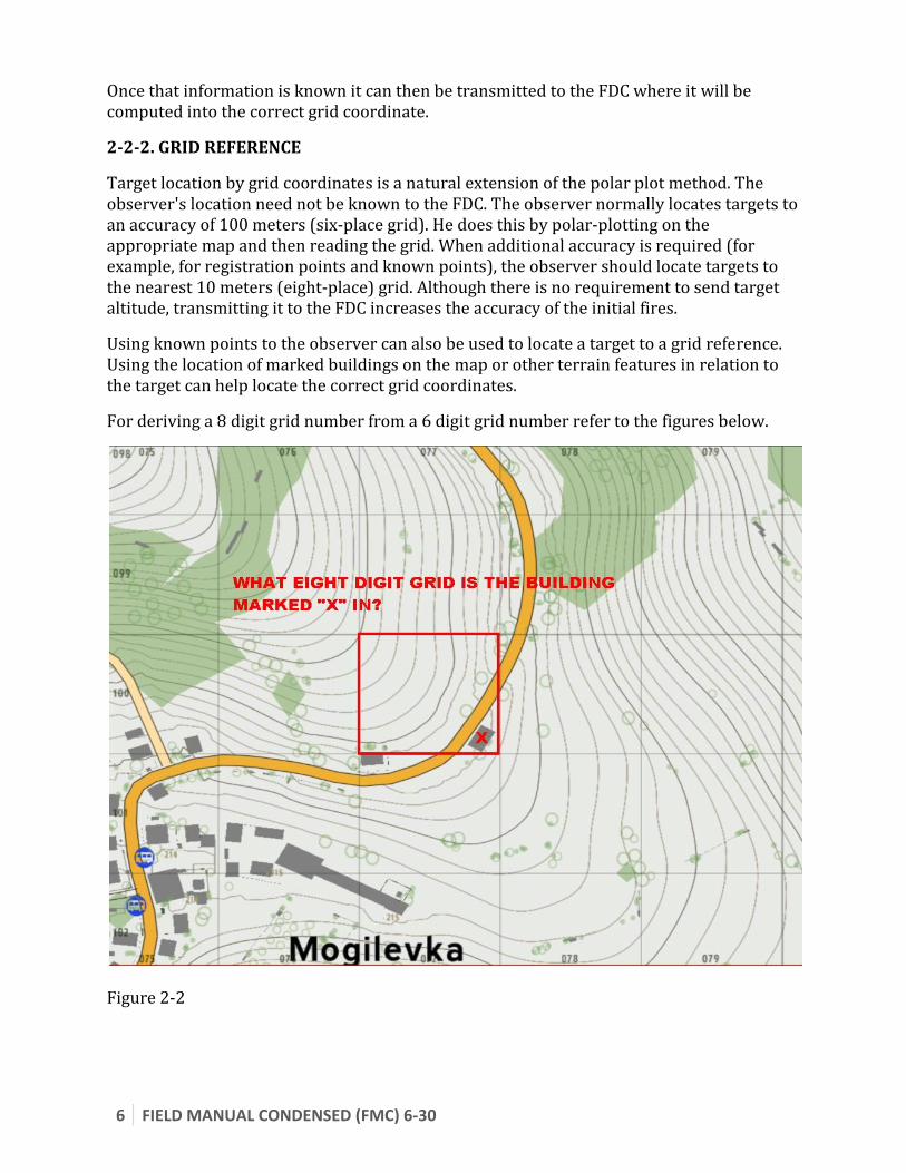
Target location by grid coordinates is a natural extension of the polar plot method. The observer's location need not be known to the FDC. The observer normally locates targets to an accuracy of 100 meters (six-place grid). He does this by polar-plotting on the appropriate map and then reading the grid. When additional accuracy is required (for example, for registration points and known points), the observer should locate targets to the nearest 10 meters (eight-place) grid. Although there is no requirement to send target altitude, transmitting it to the FDC increases the accuracy of the initial fires.
Using known points to the observer can also be used to locate a target to a grid reference. Using the location of marked buildings on the map or other terrain features in relation to the target can help locate the correct grid coordinates.
For deriving a 8 digit grid number from a 6 digit grid number refer to the figures below.
Figure 2-2

FIELD MANUAL CONDENSED (FMC) 6-30 7
Figure 2-3
2-2-3. SHIFT FROM KNOWN POINT
The observer may have one or more known points in his area of responsibility. These are readily identifiable points whose locations are known to both the observer and the FDC. The observer does not need a map to use this method; he needs only a known point. The steps in locating a target by shift from a known point are described below.
1. Identify to the FDC the known point to be used; for example SHIFT KNOWN POINT 1.
2. Identify the targets location in relation to the known point. This can be used by specifying a cardinal direction and a distance (ex: South-West, 100 meters). Preferably the observer will provide an OT direction. This is the direction of them to the target. After that they can use normal adjustment calls to relate the distance of the target from the known point.
Please see the following figures (2-4 and 2-5) for an example of a Shift from Known Point.

8 FIELD MANUAL CONDENSED (FMC) 6-30
Figure 2-4
Figure 2-5
FIELD MANUAL CONDENSED (FMC) 6-30 9
2-4. DIRECTION
Determining direction is an essential skill for the observer. Direction is an integral part of terrain-map association, adjustment of fire, and target location. There are three methods by which to determine direction.
1. Estimating. With a thorough terrain-map analysis of his zone of operation, the observer can estimate direction on the ground. As a minimum, the observer should be able to visualize the eight cardinal directions (N, NE, E, SE, S, SW, W, and NW). Because of the inaccuracy of this method, it is the least preferred method of determining direction.
2. Using a Compass. Using an M2 or a lensatic compass, the observer can measure direction to an accuracy of 10 mils.
3. Using Other Measuring Devices. The heading indicator in an aircraft can be used by the aerial observer.
2-5. DISTANCE
Once a direction to the target is determined, the observer must determine a distance to the target. There are several methods.
1. Laser. Lasers are the preferred means of determining the OT distance. When a laser is used, distance may be determined to the nearest 10 meters. This ability might not always be present.
2. Flash-to-Bang. When it is necessary to verify OT distance, the flash-to-bang technique is helpful. Sound travels at a speed of approximately 350 meters per second. Use the following equation: Elapsed time between impact and sound x 350 = Distance Multiply the number of seconds between round impact (flash) and when the sound reaches the observer (bang) by 350 meters. The answer is the approximate number of meters between the observer and the round. (This procedure can also be used to determine the distance to enemy weapon muzzle flashes.) This method is fairly inaccurate.
3. Estimation. In the absence of a more accurate method of determining distance to a target, the observer must estimate distance. The degree of accuracy in this method depends on several factors, such as terrain relief, time available, and the experience of the observer. Generally, the longer the observer remains stationary, the better he can use this technique. Some methods of estimating distance are discussed below.
a. Mental estimation can be made by use of a known unit of measure. Distance is estimated to the nearest 100 meters by determining the number of known units of measure, such as a football field (100 yards), between the observer's
10 FIELD MANUAL CONDENSED (FMC) 6-30
position and a target. For longer distances, the observer may have to progressively estimate distance. To do this, he determines the number of units of measure (for example, 100 yards) to an intermediate point and doubles the value.
b. The observer should consider the following effects of estimating distances:
Object appears nearer:
When in bright light. When the observer is looking down from a height. When the observer is looking over a depression, most of which is
hidden. When the observer is looking down a straight feature, such as a road. When the observer is looking over water, snow, or a uniform surface
such as a cultivated field. When the background is in contrast with the color of the object.
Object appears more distant:
When it is in poor light or in fog. When only a small part of the object can be seen. When the observer is looking over a depression, most of which is
visible. When the background is similar in color to that of the object.
When estimating the observer can and should use the map to verify estimated ranges against known landmarks such as groups of trees or wood lines.
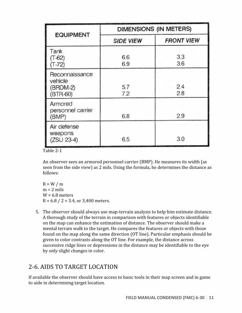
4. Binocular mil markings. Distance can be estimated by using known dimensions of vehicles and the mil relation formula (W = R x m). By applying the width of a vehicle appearing perpendicular to an observer as the lateral distance (W) and measuring the width in mils (m), the distance can be determined by solving the formula for range (R) in thousands, or R = W / m. These data, when compared with map data, will help an observer estimate distance. The dimensions of selected equipment are shown in Table 2-1 below.
FIELD MANUAL CONDENSED (FMC) 6-30 11
Table 2-1 An observer sees an armored personnel carrier (BMP). He measures its width (as seen from the side view) as 2 mils. Using the formula, he determines the distance as follows: R = W / m m = 2 mils W = 6.8 meters R = 6.8 / 2 = 3.4, or 3,400 meters.
5. The observer should always use map-terrain analysis to help him estimate distance. A thorough study of the terrain in comparison with features or objects identifiable on the map can enhance the estimation of distance. The observer should make a mental terrain walk to the target. He compares the features or objects with those found on the map along the same direction (OT line). Particular emphasis should be given to color contrasts along the OT line. For example, the distance across successive ridge lines or depressions in the distance may be identifiable to the eye by only slight changes in color.
2-6. AIDS TO TARGET LOCATION
If available the observer should have access to basic tools in their map screen and in game to aide in determining target location.

12 FIELD MANUAL CONDENSED (FMC) 6-30
2-6-1. ACE Map Tools
If ACE is available then the observer may have access to the ACE Map Tools. This contains a map compass and ruler as well as tools to draw on the map. The ruler has markings for 1:25000 and 1:50000 markings. Maps available are in a scale of 1:50000, which allows for use of the 1:25000 scale to measure distances out to 3000 meters (when multiplying the distances measured using the 1:25000 scale by 2).
2-6-2. DAGR GPS Unit
If ACE is available then the observer may have access to the DAGR GPS unit. This unit displays accurate self-location grids up to 10 digits. This unit can also be connected to a laser range finder and return remote grid coordinates up to 10 digits as well.

FIELD MANUAL CONDENSED (FMC) 6-30 13
3. Elements of the Call For Fire
The procedure to initiate a fire mission follows three steps.
Each step is initiated with the FO making the call. The FDC at the completion of each step will repeat the FO call for verification and confirmation.
1. Observer identification and warning order. 2. Target location. 3. Target description, method of engagement and method of fire control.
Expanding into more detail for each step is as follows.
3-1. Observer Identification and Warning Order
This step announces the presence of the FO over the radio network and signals that extraneous communications should be halted. The FO identification enables the FDC to place priority on that FO fire mission. If the FO does not have priority at the time/or a mission is already underway a call for hold may be sent. If a call for hold is sent the FDC should notify the held FO when they are available to accept fire missions again.
Along with the identification of the FO, the mission type is sent as well.
The mission types are as follows:
1. Adjust Fire 2. Fire for Effect 3. Suppression 4. Immediate Suppression 5. Immediate Smoke
FO should strive for first round Fire for Effect when possible.
More in-depth descriptions follow below.
1. Adjust Fire. When the observer believes that an adjustment must be made (because of questionable target location or lack of registration corrections), he announces ADJUST FIRE.
2. Fire for Effect. The accuracy required to fire for effect depends on the accuracy of target location and the ammunition being used. When the observer is certain that the target location is accurate and that the first volley should have the desired effect on the target so that little or no adjustment is required, he announces FIRE FOR EFFECT.
3. Suppression. To quickly bring fire on a target that is not active, the observer announces SUPPRESS (followed by the target identification). Suppression (S) missions are normally fired on preplanned targets, and a duration is associated with the call for fire.
14 FIELD MANUAL CONDENSED (FMC) 6-30
4. Immediate Suppression and Immediate Smoke. When engaging a planned target or target of opportunity that has taken friendly maneuver or aerial elements under fire, the observer announces IMMEDIATE SUPPRESSION or IMMEDIATE SMOKE (followed by the target location). Though the grid method of target location is the most common, any method of target location may be used in firing an immediate suppression or immediate smoke mission.
After the mission type the targeting method is communicated. This is how the FDC will plot the targets for its batteries.
1. Polar 2. Shift from Known Point 3. Grid
More in-depth descriptions follow below:
1. Polar Plot. If the target is located by the polar plot method of target location, the observer announces POLAR; for example, ADJUST FIRE, POLAR, OVER.
2. Shift From a Known Point. If the target is located by the shift from a known point method of target location, the observer announces SHIFT (followed by the known point); for example, ADJUST FIRE, SHIFT KNOWN POINT 1, OVER.
3. Grid. If the grid method of target location is being used, the word grid is not announced; for example, ADJUST FIRE, OVER.
Warning Examples:
DROPKICK: Forward Observer
RAINMAKER : Fire Direction Center
Example 1: A fire mission calling for ADJUST FIRE, POLAR
DROPKICK: RAINMAKER, THIS IS DROPKICK; ADJUST FIRE, POLAR, OVER. RAINMAKER: DROPKICK, THIS IS RAINMAKER; ADJUST FIRE, POLAR, OUT.
Example 2: A fire mission calling for FIRE FOR EFFECT, GRID
DROPKICK: RAINMAKER, THIS IS DROPKICK, FIRE FOR EFFECT, OVER RAINMAKER: DROPKICK, THIS IS RAINMAKER, FIRE FOR EFFECT, OUT
Each part of the Warning Order should be said loudly and clearly to avoid confusion.
If no problems are encountered communicating the Warning Order the FO will move on to Target Identification.

FIELD MANUAL CONDENSED (FMC) 6-30 15
3-2. Target Identification
Target identification contains the information needed to plot the target. They consist of expanding on the targeting method specified by the Warning Order.
1. Grid 2. Shift from Known Point 3. Polar
More in-depth descriptions follow below:
1. In a grid mission, six-place grids normally are sent. Eight-place grids should be sent for registration points or other points for which greater accuracy is required.
2. In a shift from a known point mission the point or target from which the shift will be made is sent in the warning order. The point must be known to both the FO and the FDC. The observer then sends the OT direction (OT direction is the azimuth of the point from the observer, and is used to orient corrections) Normally, it is sent in mils. However, the FDC can accept degrees or cardinal directions, whichever is specified by the observer. The corrections are sent next:
a. The lateral shift (how far left or right the target is) from the known point.
b. The range shift (how much farther [ADD] or closer [DROP] the target is in relation to the known point, to the nearest 100 meters).
c. The vertical shift (how much the target is above [UP] or below [DOWN] the altitude of the known point, to the nearest 5 meters). (The vertical shift is ignored unless it exceeds 30 meters.)

16 FIELD MANUAL CONDENSED (FMC) 6-30
3. In a polar plot mission, the word polar in the warning order alerts the FDC that the target will be located with respect to the observer's position. The observer's location must be known to the FDC. The observer then sends the direction and distance. A vertical shift tells the FDC how far, in meters, the target is located above or below the observer's location.
Target Identification Examples:
DROPKICK: Forward Observer
RAINMAKER: Fire Direction Center
Example 1: A fire mission that has called for polar coordinates.
DROPKICK: DIRECTION 4450, DISTANCE 600, OVER RAINMAKER: DIRECTION 4450, DISTANCE 600, OUT
Example 2: A fire mission that has called for shift from a known point.
DROPKICK: DIRECTION 2500, LEFT 100, DROP 200, OVER RAINMAKER: DIRECTION 2500, LEFT 100, DROP 200, OUT
Example 3: A fire mission that has called for grid coordinates (no identification method in Warning Order)
DROPKICK: GRID 045,056, OVER RAINMAKER: GRID 045,056, OUT
3-3. Target Description, Method of Engagement, Method of Control
The final step in initiating a call for fire is describing the target, how the target should be engaged, and how the mission will be initiated (when rounds will fire).
3-3-1. TARGET DESCRIPTION
The observer must describe the target in enough detail that the FDC can determine the amount and type of ammunition to use. The FDC selects different ammunition for different types of targets. The observer should be brief but accurate. The description should contain the following:
1. What the target is (troops, equipment, supply dump, trucks, and so forth).
2. What the target is doing (digging in, in an assembly area, and so forth).
3. The number of elements in the target (squad, platoon, three trucks, six tanks, and so forth).
FIELD MANUAL CONDENSED (FMC) 6-30 17
4. The degree of protection (in open, in foxholes, in bunkers with overhead protection, and so forth).
5. The target size and shape if these are significant. If the target is rectangular, the length and width (in meters) and the attitude (azimuth of the long axis) to the nearest 100 mils or degree should be given; for example, 400 BY 200, ATTITUDE 2800. If the target is circular, the radius should be given; for example, RADIUS 200. Linear targets may be described by length, width, and attitude.
3-3-2. METHOD OF ENGAGEMENT
The observer may indicate how he wants to attack the target. This element consists of the type of adjustment, ammunition, number of rounds, distribution and if the mission is danger close, or used as a target marking call for fire (to orient themselves or to spot a target for other units, including air). Any or all of these steps can be omitted. The FDC will make assumptions based on the TARGET DESCRIPTION and parts of his units SOP.
1. Type of Adjustment. Two types of adjustment may be employed-precision and area. Unless precision fire is specified, area fire will be used. This step only applies to missions that have called ADJUST FIRE as the mission type in the WARNING ORDER.
a. Precision fire is conducted with one weapon on a point target. It is used to destroy a specific, pinpoint target. If the target is to be destroyed, the observer announces DESTRUCTION. In this case the type of adjustment will be a creeping adjustment till the target is centered accurately and Fire For Effect can be can called.
b. Area fire is used to attack an area target. This is the normal adjustment type and no notice needs to be given, as this is the assumed type of adjustment. Adjusts will be made at towards the center of the area of fire, or an easily identifiable landmark near the target.
2. Danger Close. DANGER CLOSE will be included when targets are within 300 meters of friendly units. This will make sure targeting and adjustments by the FDC will bias away from friendly units if needed and make FDC and gun batteries stay more alert for calls to halt or cancel a fire mission.
3. Mark. MARK is included in the method of engagement to indicate that the observer is calling for rounds to mark a target or orient him. In cases such as this usually one round WP or SMOKE will be used to mark.
4. Ammunition. The observer may request any type of ammunition available and number of rounds during the adjustment or the FFE phase of his mission. HE is the default type of ammunition specified unless otherwise noted in mission briefing. The number of rounds requested is a request for volleys. If requested 3 rounds and the battery have 4 guns then 12 rounds will be shot. The battery commander or FDC

18 FIELD MANUAL CONDENSED (FMC) 6-30
defines the default number of rounds before the start of operations.
5. Distribution/Dispersion. The distribution pattern of shells is called a sheaf. Unless otherwise adjusted by the size of the target in the TARGET DESCRIPTION default distribution will be a 100-meter circular radius around the target area in an OPEN SHEAF. If the distribution is not given as a sheaf it will be given as a rectangular sized area, with width and height and attitude, much like that given in describing the target. More information on sheaf types can be found below.
It is important to remember that all of the above parts are optional, and only need to be added if the FO feels that they are important for the FDC to determine on how to engage the target.
3-3-3. METHOD OF FIRE AND CONTROL
The method of fire and control element indicates the desired manner of attacking the target, whether the observer wants to control the time of delivery of fire, and whether he can observe the target. Methods of control at my command (AMC) and time on target (TOT) are especially useful in massing fires. The AMC and TOT missions achieve surprise and maximize the effects of the initial volley on a target. When used by the observer, these methods of control can reduce the sporadic engagement of the target, or "popcorn effect," which can be the result of rounds fired when ready. Methods of fire and control are announced by the observer by use of the terms discussed below. Unit SOP will determine which of these are the default Method of Control.
1. At My Command. If the observer wishes to control the time of delivery of fire, he includes AT MY COMMAND in the method of control. When the pieces are ready to fire, the FDC announces PLATOON (or BATTERY or BATTALION) IS READY, OVER. (Call signs are used.) The observer announces FIRE when he is ready for the pieces to fire. AT MY COMMAND remains in effect throughout the mission until the observer announces CANCEL AT MY COMMAND, OVER.
2. Fire when Ready.The engaging gun battery(s) will fire when they are ready.
3. Time on Target. The observer may tell the FDC when he wants the rounds to impact by requesting TIME ON TARGET (so many) MINUTES FROM...NOW, OVER or TIME ON TARGET 0859, OVER.
4. Continuous Fire. In field artillery, mortars, and naval gunfire, continuous fire means loading and firing as rapidly as possible, consistent with accuracy, within the prescribed rate of fire for the equipment. Firing will continue until suspended by the command CEASE LOADING or CHECK FIRING.
5. Continuous Illumination. If no interval is given by the observer, the FDC determines the interval by the burning time of the illuminating ammunition in use. If any other interval is required, it is indicated in seconds.
6. Coordinated Illumination. The observer may order the interval between illuminating and HE shells, in seconds, to achieve a time of impact of the HE

FIELD MANUAL CONDENSED (FMC) 6-30 19
coincident with optimum illumination; or he may use normal AT MY COMMAND procedures.
7. Repeat. REPEAT can be given during adjustment or FFE missions.
a. During Adjustment. REPEAT means fire another round(s) with the last data and adjust for any change in ammunition if necessary. REPEAT is not sent in the initial call for fire.
b. During Fire for Effect. REPEAT means fire the same number of rounds using the same method of fire for effect as last fired. Changes in the number of guns, the previous corrections, the interval, or the ammunition may be requested.
Target Description, Method of Engagement, Method of Control Examples:
DROPKICK: Forward Observer
RAINMAKER : Fire Direction Center
Example 1: Simple, troops in open, Fire When Ready. This is as simple as it gets, even more so if Fire When Ready is assumed.
DROPKICK: INFANTRY PLATOON IN OPEN, FIRE WHEN READY, OVER RAINMAKER: INFANTRY PLATOON IN OPEN, FIRE WHEN READY, OUT
Example 2: Armor under cover (trees) , requesting number of rounds based on cover and other target factors, firing at command.
DROPKICK: ARMOR UNDER COVER, 8 ROUNDS HE, AT MY COMMAND, OVER RAINMAKER: ARMOR UNDER COVER, 8 ROUNDS HE, AT MY COMMAND, OUT
Example 3: No target information, continuous illumination firing Time on Target (this is a combination of control methods).
DROPKICK: CONTINUOUS ILLUMINATION, TIME ON TARGET 0345, OVER RAINMAKER: CONTINUOUS ILLUMINATION, TIME ON TARGET 0345, OUT
3-4. Message to Observer (MTO) and End of Mission (BDA)
After the initial call for fire is processed the FDC will use the gathered information to determine how to best engage the target. The FDC then relays this information back to the FO with their determination of how they will engage the target. MTO is dependent on the type of mission described in the warning order AND the method of control. More detail will follow below.
Depending on the warning order and method of control, after MTO follows the actual call to fire by the FO (this is mainly the case during At My Command controlled missions).

20 FIELD MANUAL CONDENSED (FMC) 6-30
After the fire mission is determined complete the FO will end the current fire mission and the FO will relay a BDA if they are able to.
3-4-1. MESSAGE TO OBSERVER (MTO)
The Message to Observer can contain the following parts.
1. Battery Information (if more than one battery is available) 2. Type of rounds assigned (HE, WP, SMOKE, ETC). 3. Number of rounds assigned (this is rounds per volley, guns in battery times rounds) 4. Target/mission identifier (this can be used for repeat fires).
MTO will only be used in missions that are not Immediate Suppression, Immediate Smoke missions, or Suppression missions. Because of time constraints or the information is already known (preplanned suppressions) the MTO can be skipped.
MTO will be communicated at different times depending on the Method of Control. If the Method of Control is At My Command then MTO will be given after the battery is ready to accept the Fire order.
These parts in more detail below:
1. Battery Information: If more than one battery is available to take the fire mission then this will be the FIRST LETTER of the battery call sign. Status is also relayed as BATTERY READY. If the MTO is sent after the battery begins to fire then this is not needed as it will be conveyed by the FDC when they relay the SHOT call.
2. Type of Rounds: This is the type of rounds that the FDC judges to be the best used for the given target. This can over ride the type of rounds requested by the FO.
3. Number of Rounds: This is the number of rounds that are to be fire per gun (volleys). This can over ride the number of rounds asked for by the FO.
4. Target/Mission Identifier: This is a letter/number combination that is used to reference the target. Examples of being: TG105, TG116, TG172. Identifiers will usually increment from a set number up per fire mission. These should be written down by the FO and used for future fire missions if repeats need to be called on them. For all intents and purposes these identifiers become Target Reference Points (TRP) and can be used as such when calling for fire missions.
MTO Examples:
DROPKICK: Forward Observer
RAINMAKER : Fire Direction Center
Example 1: One battery, so no battery ident, HE 4 rounds, and a Target ident.
RAINMAKER: BATTERY READY, HE, 4 ROUNDS, TARGET TGT102, OVER DROPKICK: BATTERY READY, HE, 4 ROUNDS, TARGET TGT102, OUT

FIELD MANUAL CONDENSED (FMC) 6-30 21
Example 2: Two batteries, battery YANKEE, WP, 8 rounds, Target ident.
RAINMAKER: Y READY, WP, 8 ROUNDS, TARGET TGT110, OVER DROPKICK: Y READY, WP, 8 ROUNDS, TARGET TGT110, OUT
3-4-2. CALL TO FIRE
If the method of control is At My Command then the FO will give the command to fire.
Call To Fire Example:
DROPKICK: Forward Observer
RAINMAKER : Fire Direction Center
Example 1: There is almost no variation to this call. Most of the time the FDC response will be the SHOT response indicating rounds are in flight.
DROPKICK: RAINMAKER, FIRE, OVER RAINMAKER: DROPKICK, SHOT, OUT
3-4-3. END OF MISSION AND BATTLE DAMAGE ASSESSMENT (BDA)
When a target has been successfully engaged and neutralized the FO will call END OF MISSION and give a Battle Damage Assessment (BDA) if applicable. BDA need only be given if a mission is not an immediate suppression or immediate smoke, or a mission that only calls for illumination.
The Battle Damage Assessment will provide a report of how effective the mission was in engaging the target and help the FDC adjust procedure for future fire missions. The description should be short and simple, including casualties, both of infantry and vehicles, and whether they are injured, damaged, killed, or disabled.
22 FIELD MANUAL CONDENSED (FMC) 6-30
3-4. Example Fire Missions
FIRE MISSION (GRID)
Initial Fire Request
Observer Z57 THIS IS Z71, ADJUST FIRE, OVER. GRID NK180513, OVER. INFANTRY PLATOON IN TH OPEN, ICM IN EFFECT, OVER. I AUTHENTICATE CHARLIE, OUT.
FDC THIS IS Z57, ADJUST FIRE, OUT. GRID NK180513, OUT. INFANTRY PLATOON IN THE OPEN, ICM IN EFFECT, AUTHENTICATE PAPA BRAVO, OVER.
Message to Observer
Observer Z, 2 ROUNDS, TARGET AF1027, OUT. DIRECTION 1680, OVER.
FDC Z, 2 ROUNDS, TARGET AF1027, OVER. DIRECTION 1680, OUT.
NOTE: Direction is sent before or with the first subsequent correction.
FIRE MISSION (SHIFT)
Initial Fire Request
Observer H66 THIS IS H44, ADJUST FIRE, SHIFT AA7733, OVER. DIRECTION 5210, LEFT 380, ADD 400, DOWN
FDC THIS IS H66, ADUST FIRE, SHIFT AA7733, OUT.

FIELD MANUAL CONDENSED (FMC) 6-30 23
35, OVER. I AUTHENTICATE PAPA, OUT.
COMBAT OP IN OPEN, ICM IN EFFECT, AUTHENTICATE LIMA FOXTROT, OVER
Message to Observer
Observer H, 1 ROUND, TARGET AA7742, OUT.
FDC H, 1 ROUND, TARGET AA7742, OVER.
FIRE MISSION (POLAR)
Initial Fire Request
Observer Z56 THIS IS Z31, FIRE FOR EFFECT, POLAR, OVER. DIRECTION 4520, DISTANCE 2300, DOWN 35, OVER. INFANTRY COMPANY IN OPEN, ICM, OVER. I AUTHENTICATE ECHO, OUT.
FDC THIS IS Z56, FIRE FOR EFFECT, POLAR, OUT. DIRECTION 4520, DISTANCE 2300, DOWN 35, OUT. INFANTRY COMPANY IN OPEN, ICM, AUTHENTICATE TANGO FOXTROT, OVER.
Message to Observer
Observer H, 1 ROUND, TARGET AA7742, OUT.
FDC Y, VT, 3 ROUNDS, TARGET AF2036, OVER.

24 FIELD MANUAL CONDENSED (FMC) 6-30
FIRE MISSION (SUPPRESSION)
Observer H18 THIS IS H24 SUPPRESS AB3104 OVER. I AUTHENTICATE DELTA, OUT.
FDC THIS IS H18, SUPPRESS AB3104, AUTHENTICATE DELTA JULIET, OVER.
FIRE MISSION (IMMEDIATE SUPPRESSION)
Observer H18 THIS IS H24, IMMEDIATE SUPPRESSION GRID 211432 AUTHENTICATION IS TANGO UNIFORM OVER.
FDC THIS IS H18, IMMEDIATE SUPPRESSION, GRID 211432, OUT.
NOTE: Immediate suppression missions are normally fired by a two-gun section using two rounds of HE or VT. However, this procedure is addressed in individual unit SOP and may vary between units.
3-5. Shell-Fuze Combinations
3-5-1. DESIRED EFFECTS
Once the observer has located a target, he must decide how he wants to attack the target to get maximum effect. A thorough knowledge of the ammunition available will allow a rapid selection of the correct type of shell and fuze to use against the target. If it is not specified by commander's guidance, the type of effect is the first decision the observer must make. He has three choices--destruction, neutralization, or suppression.
a. Destruction puts a target out of action permanently. Thirty percent or more casualties normally will render a unit combat-ineffective. Direct hits with HE or concrete-piercing (CP) shells are required to destroy hard materiel targets.
b. Neutralization knocks a target out of action temporarily. Ten percent or more casualties will neutralize a unit. Neutralization can be achieved by using any type of shell-fuze combination suitable for attacking a particular type of target. Neutralization does not require an extensive expenditure of
FIELD MANUAL CONDENSED (FMC) 6-30 25
ammunition and is the most practical type of mission.
c. Suppression of a target limits the ability of the enemy personnel in the target area to perform their jobs. Firing HE/VT or smoke creates apprehension and confuses the enemy. The effect of suppressive fires usually lasts only as long as the fires are continued. Suppression requires a low expenditure of ammunition; however, its inability to have lasting effect on a target makes it an unsuitable type of mission for most targets.
d. When deciding whether to use impact fuze action (produces ground bursts) or time fuze or proximity action (produces airbursts), the observer should consider the following:
The nature of the target.
The cover available to the enemy.
The mobility of the target.
Whether adjustment is required.
3-5-2. SHELL HE AND FUZES
Shell HE is the shell most often used by the observer in adjustment. It can be used with impact, time, or proximity (VT) fuzes for various effects.
a) Shell HE, Fuze Quick. Shell HE, fuze quick bursts on impact. It is used against the following:
Personnel standing.
Personnel prone on the ground.
Unarmored vehicles.
Light materiel.
Shell HE, fuze quick loses its effect if troops are in trenches, on uneven ground, in frame buildings, or on earthworks.
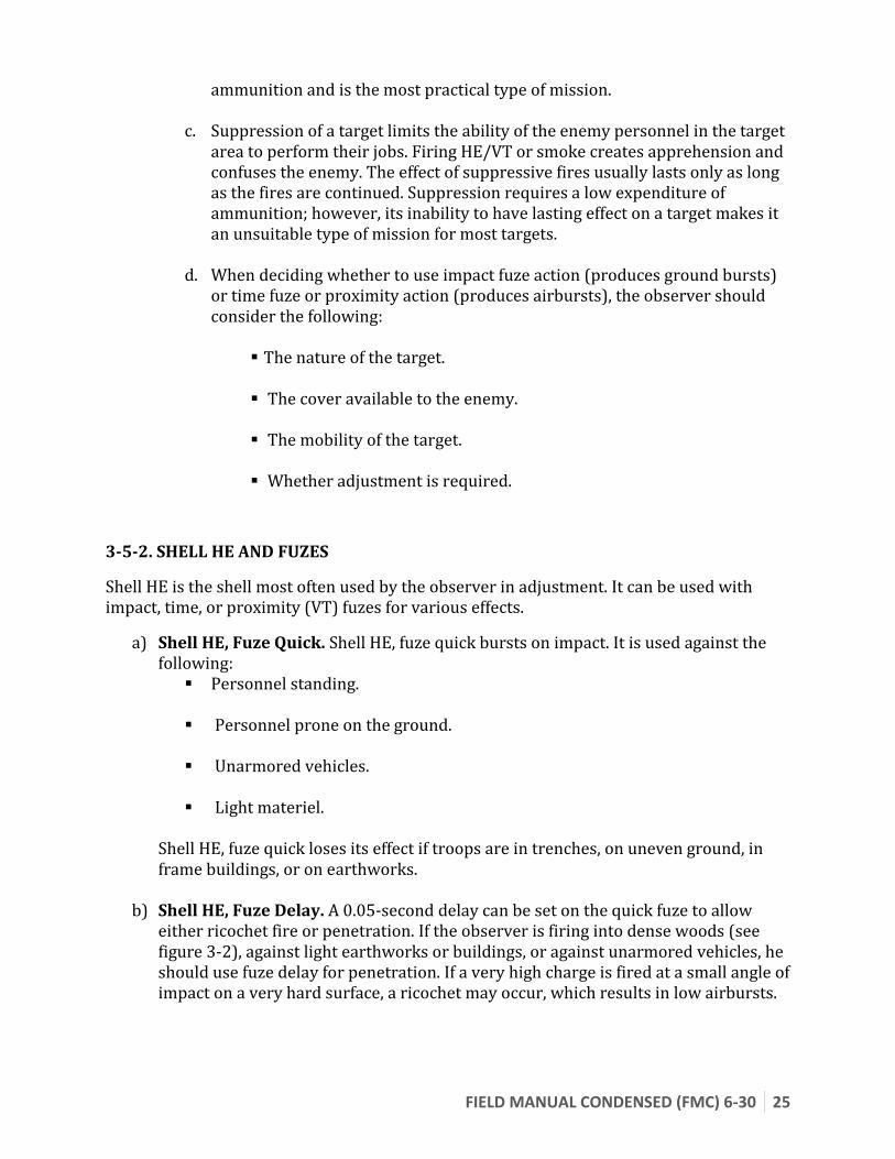
b) Shell HE, Fuze Delay. A 0.05-second delay can be set on the quick fuze to allow either ricochet fire or penetration. If the observer is firing into dense woods (see figure 3-2), against light earthworks or buildings, or against unarmored vehicles, he should use fuze delay for penetration. If a very high charge is fired at a small angle of impact on a very hard surface, a ricochet may occur, which results in low airbursts.
26 FIELD MANUAL CONDENSED (FMC) 6-30
Figure 3-2
c) Shell HE, Fuze Time. Shell HE, fuze tirne bursts in the air at a given time along the trajectory. An airburst is shown in Figure 3-3. It is used against the following:
Troops in the open.
Troops in trenches.
Troops in deep foxholes.
Troops in soft-skinned vehicles. Fuze time must be adjusted to the proper height of burst unless the firing unit has corrections for nonstandard conditions computed. Therefore, consideration should be given to another shell-fuze combination if time is critical and airbursts are desired. Fuze time should never be used for high-angle missions.
FIELD MANUAL CONDENSED (FMC) 6-30 27
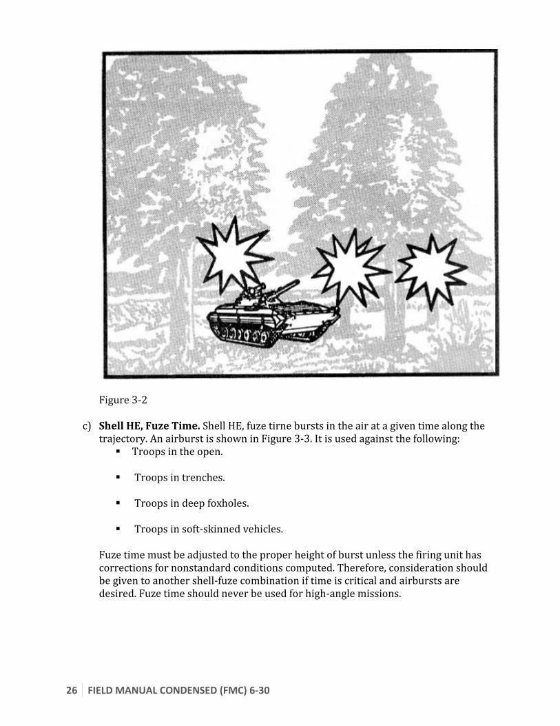
Figure 3-3
d) Shell HE, Fuze Proximity. The VT (or proximity) fuze is a radio-activated fuze that detonates at a predetermined height of burst. A VT fuze provides the same effect as fuze time but does not have to be adjusted. It is an excellent fuze to fire with shell HE for surprise and unobserved fires. Also, it is very effective in high-angle fires. It should be used in missions conducted by an aerial observer when an airburst is desired. It is used against all targets that can be attacked with fuze time.
3-5-3. SHELL WHITE PHOSPHORUS
Shell white phosphorus (WP) has four uses: incendiary, marking, obscuring, and screening. It can be used to destroy the enemy's equipment or to limit his vision. It is used against the following:
Vehicles.
Petroleum, oils and lubricants (POL) and ammunition storage areas.
Enemy observers.
Also, shell WP can be used as an aid in target location and navigation. It can be fired with fuze time to obtain an airburst.

28 FIELD MANUAL CONDENSED (FMC) 6-30
3-5-3. SHELL SMOKE
Shell smoke is a base-ejection projectile that is filled with canisters containing smoke. It is more effective than WP as a screening agent, because it lasts longer and has fewer tendencies to pillar. The direction of the wind must be considered in the use of any smoke shell (WP or hexachloroethane [HC]).
3-5-4. SHELL ILLUMINATING
The illuminating shell is a base-ejection projectile containing a flare attached to a parachute. Normally, it is used to illuminate areas of known or suspected enemy activity or to adjust artillery fire at night. Shell illuminating with a fuze setting for a graze burst may also be used to mark targets. Depending on the caliber, an illuminating shell can provide light for up to 2 minutes and can light an area of up to 1,000 meters in diameter.
3-5-5. SHELL FASCAM
The family of scatterable mines (FASCAM) includes shell FASCAM, which is fired by a 155-mm artillery weapon. It delivers antipersonnel or antitank mines against an enemy force to deny access to a particular area, to delay the attacking force, or to canalize them.
This all-weather, day-or-night mine emplacement system can be used in offensive, defensive, or retrograde operations. Antitank mines (remote anti-armor mine system [RAAMS]) are used to create antitank or anti-vehicle obstacles. Antipersonnel mines (area denial artillery munitions [ADAM]) are used in conjunction with antitank mines to create antitank obstacles difficult for dismounted personnel to breach.
Antipersonnel mines also can be used alone to create antipersonnel obstacles, to disrupt dismounted personnel operations, to restrict enemy use of terrain, and in counter-fire.
3-5-6. SHELL EXCALIBUR
The M982 Excalibur is an INS guided projectile with GPS updates during flight. It has accuracy within 5 meters when GPS is available and within 20 meters when it is not available.
The round exists in two variants:
Block I is a single unitary HE warhead with point, VT, and delay fuze options built into the round.
Block II is a cargo round variant that contains DPICM submunitions and uses a special proximity fuze for proper burst on target.
The round takes a 10 digit grid reference as its target location, but may accept less accurate grid reference as well.
Excalibur flies on a high-angle trajectory only, allowing it to dive near vertical on to targets.

FIELD MANUAL CONDENSED (FMC) 6-30 29
3-5-7. SHELL SADARM
SADARM or Sense and Destroy ARMor are a smart submunition that is able to seek out armored targets and neutralize them with an explosively formed penetrator. From time of fuze functioning to targets being within range of the submunitions is roughly 15 seconds. Observers should take this amount of time into consideration when engaging moving targets.

30 FIELD MANUAL CONDENSED (FMC) 6-30
4. Adjustment of Fire
Section I: Subsequent Corrections
An observer's prime concern is the placement of timely and accurate fires on targets. If an observer can locate the target accurately, he will request FIRE FOR EFFECT in his call for fire. Failure to locate the target accurately may result from poor visibility, deceptive terrain, poor maps, or the observer's difficulty in pinpointing the target. If the observer cannot locate the target accurately enough to warrant FFE, he may conduct an adjustment. Even with an accurate target location, if current firing data corrections are not available, the FDO may direct that an adjustment be conducted. Normally, one gun is used in adjustment. Special situations in which more than one gun is used are so noted throughout this discussion.
4-1. Adjustment Point
When it is necessary for the observer to adjust fire, he must select an adjusting point. In area missions, he must select a well-defined point near the center of the target area on which to adjust the fire. The point selected is called an adjusting point (Figure 4-1). The location of this point is included in the target location element of the call for fire in an area fire mission. In the conduct of a registration or destruction mission (precision fire), the adjusting point is the target itself.
Figure 4-1.
4-2. Spottings
A spotting is the observer's determination of the location of the burst (or the mean point of impact [MPI] of a group of bursts) with respect to the adjusting point as observed along the OT line. Spottings are made for the following:

FIELD MANUAL CONDENSED (FMC) 6-30 31
Deviation (the number of mils right or left of the OT line). Distance (whether the burst occurred beyond or short of the target). When fuze time is fired, the HOB (the number of mils the burst is above the target).
Spottings must be made by the observer the instant the bursts occur except when the spottings are delayed deliberately to take advantage of drifting smoke or dust. The observer is usually required to announce his spottings during his early training; experienced observers make spottings mentally. The observer should consider the most difficult spottings first. The sequence of spottings is HOB (air or graze), range (over or short), and deviation (left or right).
a. Height-of-Burst Spotting. The HOB spotting may be any one of the following: AIR--a round or group of rounds that bursts in the air. The number of mils
also is given. For example, a burst 10 mils above the ground would be spotted as AIR 10.
GRAZE--a round or group of rounds that detonates on impact. MIXED--a group of rounds that results in an equal number of air bursts and
graze bursts. MIXED AIR--a group of rounds that result in both air bursts and graze bursts
when most of the bursts are air bursts. MIXED GRAZE--a group of rounds that result in both air bursts and graze
bursts when most of the bursts are graze bursts.
b. Range Spotting. Definite range spottiness is required to make a proper range adjustment. Any range spotting other than DOUBTFUL, LOST, or UNOBSERVED is definite. Normally, a round which impacts on or near the OT line results in a definite range spotting. Figure 4-2 shows the approximate areas for various range spottiness.
Figure 4-2. An observer may make a definite range spotting when the burst is not on or near the OT line by using his knowledge of the terrain, drifting smoke, shadows, and wind. However, even experienced observers must use caution and good judgment when making such spottiness. Possible range spottiness are as follows:
OVER--a round that impacts beyond the adjusting point. SHORT--a round that impacts between the observer and the adjusting point.

32 FIELD MANUAL CONDENSED (FMC) 6-30
TARGET--a round that impacts on the target. This spotting is used only in precision fire (registration or destruction missions).
RANGE CORRECT--a round that impacts at the correct range. DOUBTFUL--a round that can be observed but cannot be spotted as OVER,
SHORT, TARGET, or RANGE CORRECT. LOST--a round whose location cannot be determined by sight or sound. UNOBSERVED--a round not observed but known to have impacted (usually
heard). UNOBSERVED OVER or SHORT--a round not observed but known to have
impacted over or short.
c. Deviation Spotting. A deviation spotting is the angular measurement from the adjusting point to the burst as seen from the observer's position. During a fire mission, the observer measures the deviation, in mils, with his binoculars (or another angle-measuring instrument). Deviation spottings are measured to the nearest 5 mils for area fires and 1 mil for precision fires. Possible deviation spottings are as follows:
LINE--a round that impacts on line (LN) with the adjusting point as seen by the observer (on the OT line).
LEFT--a round that impacts left (L) of the adjusting point in relation to the OT line.
RIGHT--a round that impacts right (R) of the point in relation to the OT line.
EXAMPLE
An observer spots a round to the right of the OT line. He measures the angular deviation as 40 mils. His deviation spotting is 40 RIGHT.
Deviation spottings are taken from the center of a single burst or, in the case of platoon or battery fire, from the center of the group of bursts. Deviation spottings should be made as accurately as possible to help in obtaining definite range spottings.
FIELD MANUAL CONDENSED (FMC) 6-30 33
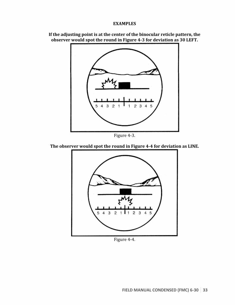
EXAMPLES
If the adjusting point is at the center of the binocular reticle pattern, the observer would spot the round in Figure 4-3 for deviation as 30 LEFT.
Figure 4-3.
The observer would spot the round in Figure 4-4 for deviation as LINE.
Figure 4-4.

34 FIELD MANUAL CONDENSED (FMC) 6-30
d. Unobserved Spotting. At times, the observer may be able to make a spotting even though he is unable to see the round impact.
EXAMPLE
The observer hears but does not see the round impact and the only possible place the round could have impacted and not been visible to the observer is in a ravine beyond the adjusting point. He assumes that the burst is beyond the
adjusting point and spots it as UNOBSERVED, OVER.
e. Lost Spotting. If the observer is unable to locate the round (either visually or by sound), the round is spotted LOST. A round may be lost for various reasons:
It may be a dud (nonfunctioning fuze), resulting in no visual or audible identification.
The terrain may prevent the observer from spotting the round or its smoke. The weather may prevent the observer from spotting the round or its smoke. Enemy fire may prevent the observer from hearing or seeing the round. The FO simply may have failed to spot the round. Errors by the FDC or the firing piece may cause the round to be lost.
When dealing with a lost round, the FO must consider his own experience, the level of FDC and/or gun section training, and the location of friendly elements with respect to the target. The observer should take corrective action based on his confidence in the target location, the accuracy of fire on previous missions, whether the lost round is an initial round or a subsequent round, and the urgency of the mission. When a round is lost, positive action must be taken. The observer can start a number of corrective procedures, such as one or more of the following:
Begin a data check throughout the system, starting with his target location data and his call for fire.
Request a WP round, a smoke round, or a 200-meter airburst with HE on the next round.
Repeat. End the mission and start a new mission. Make a bold shift. The observer should be very careful in making a bold
distance or deviation change when the target plots in the vicinity of friendly troops.
FIELD MANUAL CONDENSED (FMC) 6-30 35
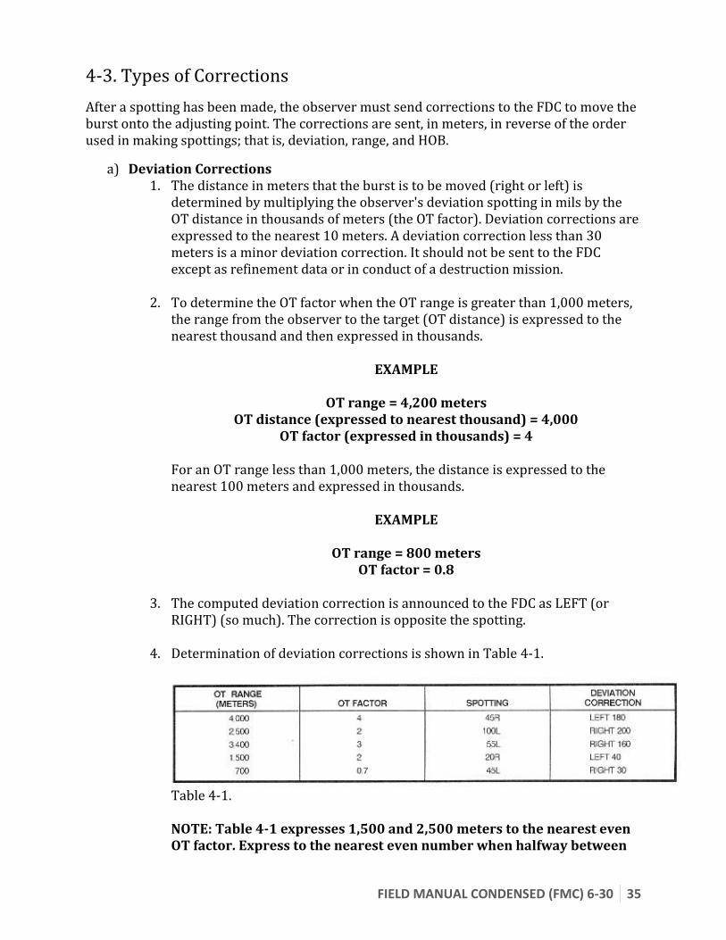
4-3. Types of Corrections
After a spotting has been made, the observer must send corrections to the FDC to move the burst onto the adjusting point. The corrections are sent, in meters, in reverse of the order used in making spottings; that is, deviation, range, and HOB.
a) Deviation Corrections 1. The distance in meters that the burst is to be moved (right or left) is
determined by multiplying the observer's deviation spotting in mils by the OT distance in thousands of meters (the OT factor). Deviation corrections are expressed to the nearest 10 meters. A deviation correction less than 30 meters is a minor deviation correction. It should not be sent to the FDC except as refinement data or in conduct of a destruction mission.
2. To determine the OT factor when the OT range is greater than 1,000 meters, the range from the observer to the target (OT distance) is expressed to the nearest thousand and then expressed in thousands.
EXAMPLE
OT range = 4,200 meters OT distance (expressed to nearest thousand) = 4,000
OT factor (expressed in thousands) = 4
For an OT range less than 1,000 meters, the distance is expressed to the nearest 100 meters and expressed in thousands.
EXAMPLE
OT range = 800 meters OT factor = 0.8
3. The computed deviation correction is announced to the FDC as LEFT (or
RIGHT) (so much). The correction is opposite the spotting.
4. Determination of deviation corrections is shown in Table 4-1.
Table 4-1. NOTE: Table 4-1 expresses 1,500 and 2,500 meters to the nearest even OT factor. Express to the nearest even number when halfway between

36 FIELD MANUAL CONDENSED (FMC) 6-30
two numbers.
5. Angle T (Figure 4-5) is the angle formed by the intersection of the gun-target (GT) line and the OT line with its vertex at the target. If angle T is 500 mils or greater, the FDC should tell the observer this. If the observer is told that angle T is 500 mils or greater, at first he continues to use his OT factor to make his deviation corrections. If he sees that he is getting more of a correction than he asked for, he should consider cutting his corrections to better adjust rounds onto the target.
Figure 4-5. Angle-T
b) Range Correction. When making a range correction, the observer attempts to "add" or "drop" the adjusting round, along the OT line, from the previous burst to the target. If his spotting was SHORT, he will add; if his spotting was OVER, he will drop. The observer must be aggressive in the adjustment phase of an adjust fire mission. He must use every opportunity to shorten that phase. He should make every effort to correct the initial round onto the target and enter FFE as soon as possible. Successive bracketing procedures should be used only when time is not critical. When conducting an adjustment onto a target, the observer may choose to establish a range bracket. Different types of range adjustments are discussed in Section II.
FIELD MANUAL CONDENSED (FMC) 6-30 37
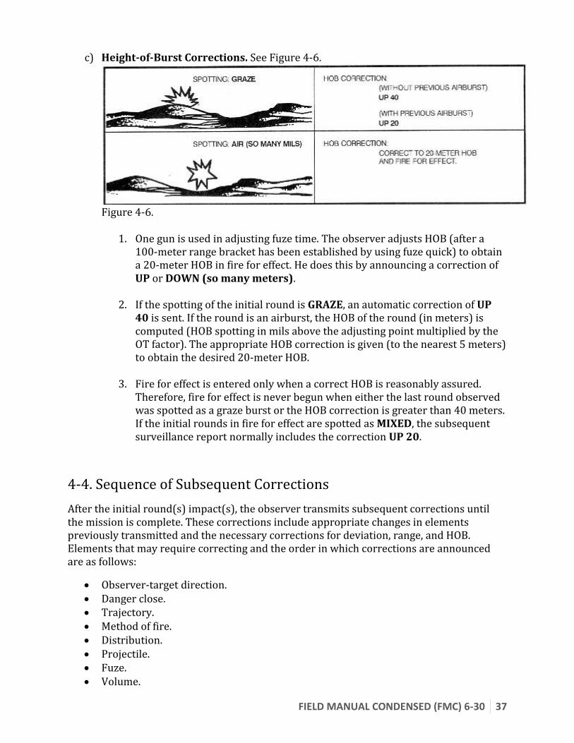
c) Height-of-Burst Corrections. See Figure 4-6.
Figure 4-6.
1. One gun is used in adjusting fuze time. The observer adjusts HOB (after a 100-meter range bracket has been established by using fuze quick) to obtain a 20-meter HOB in fire for effect. He does this by announcing a correction of UP or DOWN (so many meters).
2. If the spotting of the initial round is GRAZE, an automatic correction of UP 40 is sent. If the round is an airburst, the HOB of the round (in meters) is computed (HOB spotting in mils above the adjusting point multiplied by the OT factor). The appropriate HOB correction is given (to the nearest 5 meters) to obtain the desired 20-meter HOB.
3. Fire for effect is entered only when a correct HOB is reasonably assured. Therefore, fire for effect is never begun when either the last round observed was spotted as a graze burst or the HOB correction is greater than 40 meters. If the initial rounds in fire for effect are spotted as MIXED, the subsequent surveillance report normally includes the correction UP 20.
4-4. Sequence of Subsequent Corrections
After the initial round(s) impact(s), the observer transmits subsequent corrections until the mission is complete. These corrections include appropriate changes in elements previously transmitted and the necessary corrections for deviation, range, and HOB. Elements that may require correcting and the order in which corrections are announced are as follows:
Observer-target direction. Danger close. Trajectory. Method of fire. Distribution. Projectile. Fuze. Volume.

38 FIELD MANUAL CONDENSED (FMC) 6-30
Deviation correction. Range correction. Height-of-burst correction. Target description. Mission type and/or method of control. Splash. Repeat.
Any element for which a change or correction is not desired is omitted. Guidelines for subsequent corrections are discussed below.


