\ Í>I|0í3H DEPARTMENT OF THE ARMY FIELD MANUAL It'. .! MARINE CORPS FLEET MARINE FORCE MANUAL ai/lkMr/fri FM 101-31-1 FMFM 11-4 -, ' / // : -a -i, >4'. :\ ' *. v it;- ..•m. \ïx 1 ^ ' ' (!< ’ 1 '•¿ 4- \/ STAFF 0FFICERS\ FIELD MANUAL NUCLEAR WEAPONSxEMRLOYMENT DOCTRINE AND PROCEDURES \ \ \ \\ RETURN TO AÍ ROOM 1 A 518 PENTAGON DEPARTMENTS OF THE ARMY A.ND THE NAVY FEBRUARY 1968
Transcript
\
Í>I|0í3H
DEPARTMENT OF THE ARMY FIELD MANUAL
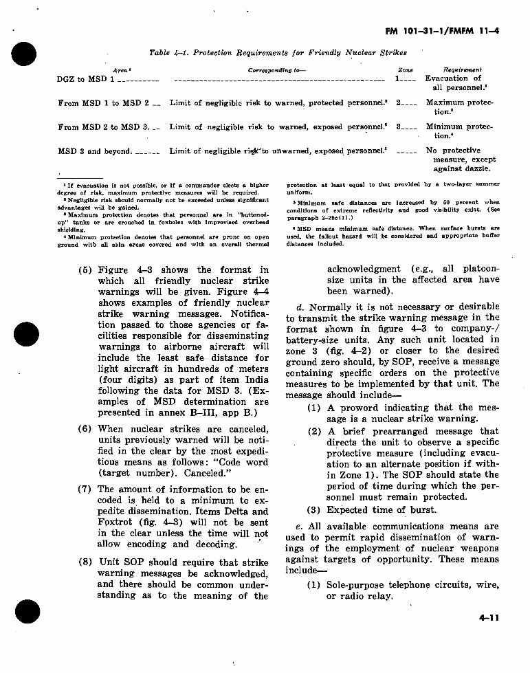
It'.
.! MARINE CORPS FLEET MARINE FORCE MANUAL
ai/lkMr/fri
FM 101-31-1 FMFM 11-4
-, ' / //
: -a
■-i,
■>4'.
:\ ' *. v it;-
..•m. ■
\ïx 1 ^ ' '
(!<■’
1 '•¿■4-
\/
STAFF 0FFICERS\ FIELD MANUAL NUCLEAR WEAPONSxEMRLOYMENT
DOCTRINE AND PROCEDURES \ \ \
\\ RETURN TO AÍ ROOM 1 A 518 PENTAGON
DEPARTMENTS OF THE ARMY A.ND THE NAVY FEBRUARY 1968
U
/
)
I
I
\
/
i
x
!
\
> •
\
\
:y
4
ü Change
No. 1
i m
FM 101-31-1/FMFM C 1
DEPARTMENTS OF THE ARMY AND THE NAVY
WASHINGTON, D.C., 19 December 1969
STAFF OFFICERS’ FIELD MANUAL
NUCLEAR WEAPONS EMPLOYMENT
DOCTRINE AND PROCEDURES
FM 101-31-1/FMFM 11-4, 15 February 1968, is changed as follows:
1. Remove old pages and insert new pages as indicated below.
Remoce pages
1- 1 and 1-2 2- 1 and 2-2 2- 15 and 2-16 3- 1 through 3-6 3- 9 through 3-12 4- 7 through 4-14 5- 1 through 5-4 6- 3 and 6-4 B-l through B~4 B-ll and B-12 B—23 and B—24 B—31 and B—32 B—43 and B—44 B-55 and B-56 B—59 and B—60 B-65 and B-66 Glossary-1
Imert paçet
1- 1 and 1-2 2— 1 and 2—2 2- 15 through 2-16 3- 1 through 3-6 3- 9 through 3-12 4- 7 through 4-13 5- 1 through 5-4 6- 3 and &-4 B-l through B-4 B-ll and B-12 B-23 and B-24 B-31 and B-32 B-43 and B-44 B-55 and B-56 B-59 and B-60 B-65 and B-66 Glossary-1, Glossary-2
2. A star indicates new or changed material. 3. File this change sheet in front of the manual for reference purposes.
RETURN TO h.,iu LIOiiÂRY ROOM 1 A 518 PENTAGON
1, FM 101-31-1/FMFM 11-4
By Order of the Secretaries of the Army and the Navy: #
Official : KENNETH G. WICKHAM, Major General, United States Army, The Adjutant General.
W. C. WESTMORELAND, ' General, United States Army, Chief of Staff. 1
1
i
I
C. B. DRAKE, Major General, U.S. Marine Corps, Assistant Chief of Staff G-3
Distribution : Army :
To be distributed in accordance with DA Form 12-11 requirements for Staff Officers’ Field Manual, Nuclear Weapons Employment.
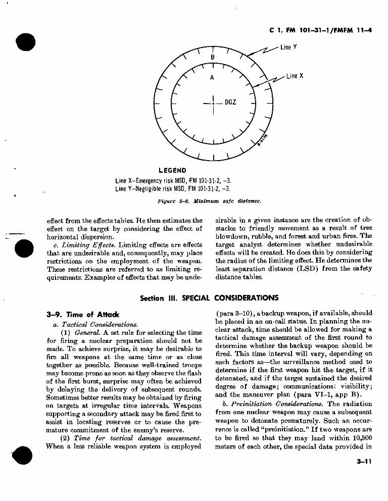
INTRODUCTION INITIAL EFFECTS OF NUCLEAR WEAPONS General Blast and shock Thermal radiation Initial nuclear radiation Combined effects and special considerations
CHAPTER 3.
Section I. II.
III.
TARGET ANALYSIS General Techniques for target analysis Special considerations
CHAPTER 4. COMMAND RESPONSIBILITIES, STAFF PROCEDURES, AND TECHNIQUES OF EMPLOYMENT
5. OPERATIONS IN RESIDUAL RADIATION AREAS 6. PROTECTIVE MEASURES
Section I. II.
III.
APPENDIX A.
B.
General Individual protective measures Unit protective measures
REFERENCES
TARGET ANALYSIS Annex B-I.
B-II. Tab B-II-1.
B-I 1-2. B-II-3.
Annex B-III.
B-IV. B-V.
B-VI. B-VII.
Probability and concept of damage Damage estimation Index method of damage estimation Visual method of damage estimation Numerical method of damage estimation Limiting requirements Selection of the desired ground zero Special considerations Poststrike damage prediction Friendly vulnerability
GLOSSARY
INDEX y *fni* mi manual supersedes FM 101-31-1, 1 February 1963, including all changes.
1—1. Purpose This manual provides guidance to commanders and staff officers in the operational and logistical aspects of nuclear weapon employment in combat operations.
1—2. Scope a. The doctrine presented in this manual is
basically concerned with nuclear weapon employ- ment within the field army and the Fleet Marine Force. When the manual discusses special ammu- nition logistics and vulnerability analyses, the scope is extended to include the area of operations.
b. Guidance is presented for the employment of nuclear weapons in the attack of targets on or near the earth’s surface.
e. The complete manual series (FM 101-31-1, FM 101-31-2, and FM 101-31-3) includes the following information:
(1) The U.S. Army and the U.S. Marine Corps doctrine for employment of nuclear weapons.
(2) The effects expected from nuclear weapons.
(3) Techniques of target analysis. (4) Command and staff procedures in nuclear
weapon employment. (5) Guidance for conducting tactical opera-
tions in a nuclear environment. (6) Defensive measures, individual and unit,
to reduce the effects of enemy-delivered weapons. (7) Tabular information concerning target
response and troop safety for a family of hypo- thetical weapons and for stockpile weapons.
(8) Pertinent portions of STAN AGs 2083, 2103, 2104, 2111, SOLOGs 89,- 123, 128, 130 and SEASTAG 2083.
d. This manual repeats information presented in other field manuals only as required for clarity or consistency. The manual should, therefore, be used in conjunction with other applicable manuals. For a discussion of the employment of nuclear weapons in the air defense role, see FM 44-1A.
★1-3. Recommended Changes Users of this manual are encouraged to submit recommendations to improve the manual. Com- ments should be keyed to the specific page, para- graph, and line of text in which the change is rec- ommended. Reasons will be provided for each comment to insure understanding and complete evaluation. Comments should be prepared using DA Form 2028 (Recommended Changes to Publi- cations) and forwarded direct to the Commanding Officer, U.S. Army Combat Developments Com- mand Institute of Nuclear Studies, Fort Bliss, Texas 79916. Originators of proposed changes that would constitute a significant modification of ap- proved Army doctrine may send an information copy, through command channels to the Command- ing General, U.S. Army Combat Developments Command, Fort Belvoir, Virginia 22060, to facili- tate review and followup. Marine Corps users of this manual will submit comments to the Com- manding General Marine Corps Development and Education Command (ATTN : 45R) Quan- tico, Virginia 22134.
1—4. Organizations of the Manual Series
The material is divided into three separate manuals—
a. This manual provides doctrine applicable to active nuclear warfare. It contains the U.S. Army and U.S. Marine Corps concepts for nuclear weapon employment and the command and staff actions required to carry out these concepts. Ap- pendix B presents detailed technical procedures concerning target analysis.
b. FM 101-31-2 contains classified defense in- formation concerning the nuclear weapons in the U.S. stockpile. It provides the data necessary for target analysis. It presents items of. information concerning technical procedures that are not in- cluded in this manual because of their security classification. FM 101-31-2 is designed for use in active nuclear combat, field training exercises (FTX), and command post exercises (CPX).
1-1
C 1, FM 101-31-1/FMFM 11-4
FM 101-31-2 (Modified) is intended to be used by NATO members in actual combat, FTX, and CPX.
c. FM 101-31-3 provides data concerning a family of hypothetical nuclear weapons. It pro- vides the data necessary for target analysis. FM 101-31-3 is designed specifically for use in unclas- sified training of the staff officer, particularly the nuclear weapon employment officer. It is not in- tended for field exercises or command post exer- cises by U.S. Forces, but can be so used by non-U.S. forces. The illustrative problems in appendix B, this manual, use data from FM 101-31-3.
d. The organization of the material in FM 101- 31-2 and FM 101-31-3 is, in most cases, identical. Differences between the U.S. stockpile weapons and the family of hypothetical weapons exist; these differences are intentional and are designed to protect the security of the actual weapons. Facil- ity in the use of FM 101-31-3 will insure facility in the use of FM 101-31-2.
1—5. Concepts for Nuclear Weapons Employment
The doctrine in this manual is based on the follow- ing basic concepts :
a. The U.S. Army and U.S. Marine Corps are organized, equipped, and trained to fight in nuclear warfare, nonnuclear warfare, or under the threat of nuclear warfare. In the latter case, units are prepared to take the actions indicated in this manual should nuclear warfare begin.
&. Nuclear weapons may be employed within the area of operations when the theater commander announces that their use has been authorized.
c. Once nuclear warfare has commenced, the
\ \ authomtylto employ nuclear weapons is decen- tralize!. *'i
d. UMi«a States nuclear weapons may be em- ployed in support of Allied forces, using either United States or Allied delivery means. The nuclear warhead section (to include artillery pro- jectiles) remains under the control of United States military personnel until time of launching or firing.
e. A commander who plans to employ a nuclear weapon coordinates with any adjacent unit com- mander into whose zone, or sector, militarily sig- nificant weapon effects are expected to extend. Lacking concurrence, the commander requests authority to fire from the next higher commander who controls both sectors.
/. Nuclear firepower is a form of combat power. Nuclear weapons may, on occasion, be used alone to accomplish tasks that might otherwise require the maneuver of close combat units ; however, most tasks require a combination of fire and maneuver. Plans for the employment of nuclear firepower, nonnuclear firepower, and maneuver forces are integrated to provide decisive results.
g. Nuclear weapons are employed to destroy or degrade enemy combat capaibilities. Consistent with the requirements imposed by the tactical mis- sion, casualties among civilian personnel are held to a minimum. Destruction of manmade structures or natural terrain features, tree blowdown or fire areas, and creation of high-intensity residual con- tamination areas may create undesired obstacles to movement. Consistent with military objectives, un- necessary destruction and contamination should be held to a minimum.
h. Commanders employ the smallest and most readily available weapon with a suffi-
1-2
FM 101-31—1/FMFM 11-4
ciently high probability of providing the cov- erage that insures the desired results.
i. Commanders employ surface bursts when surface bursts accomplish the results desired more effectively than do Airbursts. (Factors to be considered are presented in para 4-10.)
j. Commanders conduct poststrike analysis as required.
1-6. Terms and Definitions Terms and definitions useful for a better
understanding of this manual may be found in AR 320-5 and in JCS Pub 1. Certain terminology is oriented toward nuclear weapon
employment and is not found in the afore- mentioned publications. To provide definitions of terms and phrases peculiar to nuclear weapon employment, a glossary is contained in the back of this manual.
1-7. Nuclear Play For maneuver control, FM 105-5 and the
FM 105-6 Nuclear Play Calculator series of field manuals has been designed. FM 105-6-1, FM 105-6-2, and FM 105-6-3, cover the un- classified and classified portions of nuclear gaming and include techniques and tables that allow considerations of probabilities to be entertained in the gaming.
1-3
's
*
C 1, FM 101-31-1/FMFM 11-4
CHAPTER 2
INITIAL EFFECTS OF NUCLEAR WEAPONS
Section I. GENERAL
2-1. General а. The effective employment of nuclear weapons
requires an understanding of the effects produced by these weapons, the response of various target elements to these effects, the distance at which damage or casualties may be produced, the methods of estimating the results of nuclear bursts under various conditions, and the variability of the pre- dicted results.
б. This chapter presents a general qualitative discussion of initial nuclear weapon effects and their military significance. TM 23-200 presents a quantitative discussion of effects, and provides the nuclear weapon employment officer with a means by which he can determine the distance to which various effects extend.
2-2. Description of Nuclear Detonations а. Release of Energy. The magnitude of the
energy released in a nuclear explosion exceeds enormously the energy released in a nonnuclear ex- plosion. Two types of nuclear reactions produce energy—fission and fusion. A fusion reaction is approximately three times as efficient per kilogram of fuel as is a fission reaction. The energy released (yield) by a nuclear detonation is measured in thousands of tons of TNT equivalent (kiloton (KT) ), or in millions of tons of TNT equivalent (megaton (MT)). As a result of the sudden re- lease of immense quantities of energy, a fireball is formed. The fireball rapidly grows in size and rises high into the atmosphere. The initial temper- ature of the fireball ranges into millions of degrees, and the initial pressure ranges to millions of atmospheres.
б. Partition of Energy. Transfer of energy from the weapon to the surrounding media begins with the actual nuclear explosion and is exhibited as three distinct effects.
(1) Blast. Mechanical shock effects are pro-
duced by a high-pressure impulse or wave as it travels outward from the burst.
(2) Thermal radiation. Heating effects result as objects in the surrounding area absorb thermal energy released by the burst.
(3) Nuclear radiation. Ionizing effects are produced when nuclear radiation emitted by the burst is absorbed.
c. Valuation Parameters. The percentage of the total energy emitted, appearing as blast, thermal radiation, or nuclear radiation, depends on the al- titude at which the burst takes place (subsurface, surface, air) and on the physical design of the weapon.
2-3. Damage Criteria and Radius of Damage
a. General. Two specific types of information pertaining to the military use of nuclear weapons have been developed through weapon tests. These specific effects data appear in TM 23-200.
(1) The thermal, blast, or nuclear radiation levels required to cause a particular degree of dam- age to a materiel or a personnel target element.
(2) The distance to which the required levels will extend from a given weapon.
h. Damage Analysis. The nuclear weapon em- ployment officer uses data derived from effects {a above) to estimate the damage that a specific weapon will cause to a target. By knowing the ap- proximate damage each weapon will cause, be selects the most appropriate weapon to accomplish the mission from those available for use. ■jçc. Degrees of Materiel Damage.
(1) Damage to materiel is classified by de- grees as light, moderate, or severe. These degrees of damage are described in (a) through (c) below.
(a) Light damage does not prevent the immediate use of an item. Some repair by the user may be needed to make full use of the item.
2-1
C 1, FM 101-31-1/FMFM 11-4
(b) Moderate damage prevents use of an item until extensive repairs are made.
(c) Severe damage prevents use of the item permanently. Kepair, in this case, is generally im- possible or is more costly than replacement.
(2) Moderate damage usually is all that is required to deny the use of equipment. In most situations, this degree of damage will be sufficient to support tactical operations. There may be situa- tions, such as the attack of a bridge, in which only severe damage will produce the desired results.
d. Personnel Casualties. Personnel casualties (combat ineffectives), unlike damage are not clas- sified as to degree. Whenever personnel cannot perform their duties as a result of the weapon (s) employed against them, they are considered casu- alties. Some personnel will be effective immedi- ately following attack but will later become combat ineffective because of the delayed effects of nuclear radiation.
e. Personnel Casualties Versus Materiel Dam- ' age. For most tactical targets, it is desirable to base target analysis on casualties rather than on damage to materiel. Exceptions are targets such as missile launchers, bridges, and other key struc- tures.
/. Radius of Damage. The primary tool used in estimating damage to the target is referred to as the radius of damage (RD). The radius of damage is the distance from the ground zero (GZ) at which the probability of an individual target element receiving a specified degree of damage is 50 percent. Every nuclear burst produces a radius of damage for each associated target element and a degree of damage. For example, a weapon will
have one radius of damage for moderate damage to wheeled vehicles, another radius of damage for severe damage to wheeled vehicles, and another for casualties to protected personnel. For purposes of this discussion, all specified target elements within the radius of damage are assumed to receive the desired degree of damage. Appendix B pre- sents a more detailed discussion of the concept of radius of damage.
2-4. Types of Burst—Definition and Significance
Nuclear weapons may be burst at any point from deep below the surface to very high in the air. Tactically, nuclear bursts are classified according to the manner in which they are employed. The terms listed below and their associated definitions are used in the remainder of this manual. For technical definitions of the various heights of burst, see TM 23-200.
a. Subsurface Burst (less than 0 meter height of burst). This type of burst generally is used to cause damage to underground targets and struc- tures and to cause cratering.
b. Impact or Contact Surface Burst (0 meter height of burst). This type of burst is used to cause fallout, ground shock and cratering, and may be used against hard underground targets located relatively near the surface of the earth.
c. Nuclear-Surface Burst. This type of burst causes fallout because the fireball touches the sur- face. Because of this fallout producing aspect, employment of this type of burst is limited.
d. Low Airburst. This type of burst is used for the most effective coverage of damage to the great majority of ground targets of inter-
2-2
FM 101-31-1/FMFM 11-4
est to troops in the field. As used in this man- ual, this height of burst will preclude fallout. It is the height of burst most frequently used.
e. High Airburst. A high airburst is used in special cases for maximum coverage of “soft” ground targets, such as light frame buildings,
and to reduce the intensity of induced radia- tion in the vicinity of the ground zero. How- ever, this height of burst reduces the radius of damage for most target elements and, conse- quently, receives little attention.
Section II. BLAST AND SHOCK
2-5. Airblast, General
a. Airblast is produced by nearly all types of bursts. In general—
(1) The airburst produces the most dam- age from the blast effect along the ground. When the blast wave from an airburst strikes the earth, it is reflected by the earth’s surface. The reflected blast wave then reinforces the incident blast wave, producing overpressures higher than those in the incident wave. This increase in overpressure results in a greater area coverage for blast effects since the distance to which low magnitude overpressures or dynamic pressures extend are increased. This increase in in distance provides an additional damage-producing capability for “soft” targets which are destroyed or damaged by the relatively low pressures.
(2) The surface burst produces less total area coverage for blast damage than the airburst to most military targets. This is because there is less reinforce-
ment of the blast wave. Furthermore, some of the blast energy is used to produce a crater, and some of the blast energy is transmitted as ground shock.
(3) The subsurface or underground burst produces the least blast damage to most military targets. Again, there is less reflection and reinforcement of the blast wave. Also, more blast energy is used to produce a larger crater, and some of the blast energy is transmitted as ground shock. The deeper the weapon is burst, the less airblast is produced.
b. The pressure is highest at the leading edge of a blast wave. As the blast wave moves away from the fireball, the pressure at the leading edge steadily decreases, and the pressure behind the leading edge drops off to normal. Figure 2-1 shows the relative pressures behind the blast wave at a short distance from the burst. After the blast wave has traveled a greater distance from the fire- ball, the pressure in the air behind the blast wave drops below that of the surrounding
I Whllt I W W W ** I W
edge of blast wave
Pressure at trailing edge of blast wave
Distance
Figure 2-1. Variation of pressure within the blast wave.
2-3
£
(+)
Normal
atmospheric
pressure
(-)
Peak overpressure
\
Positive^ sphase-^
Negative phase
Positive phase
0/76
Í2- ‘Distance CD ®
Peak overpressure
LEGEND
Location of shock fiont. Pressure curve.
Figure 2-2. Overpressure versus distance from the burst center.
L
FM
10
1-3
1-1
/FM
FM
11
-4
.3*'
Tima |-*—
FM 101-31-1/FMFM 11-4
» Q> e- a> s
Time
100 500 Relative distance (meters)
Time
Tï-o/yj 1000
Figure 2-S. The duration of the blast wave increases with the distance from the ground zero.
10 KT 50 KT
Time Time a-oJV£ Time
Figure 2-4. The duration of the blast wave increases with the yield at the same distance from GZ.
atmosphere and a “negative phase” is formed. Figure 2-2 shows a blast wave at two different distances from its origin during its expansion. The negative phase is shown behind the blast wave after it has expanded.
c. Both the positive and the negative phases produce damage ; high pressures in the positive phase cause the most damage. In analyzing a target for probable blast effect, the effects of the negative phase are disregarded.
2-6. Damaging Pressures As the blast wave moves outward in all
directions, it exerts two types of damaging pressures on all materiel in its path—
a. Static Overpressure. This is a squeezing or crushing force that surrounds the object and continues to apply pressure from all sides until the pressure returns to normal. During the time that the blast wave passes an object, a static pressure differential exists. The side nearest the burst receives high pressures be- fore the side away from the burst. This pres- sure differential produces a temporary force away from the burst that causes damage in addition to that caused by the squeezing of the
2-5
object At any given point away from the ground zero, the highest static overpressure reached during passage of the blast wave is called the “peak” static overpressure for that point. Targets that are sensitive to, and are damaged primarily by, static overpressures are called diffraction targets.
b. Dynamic Pressure. As the blast wave moves away from the burst point, it is accom- panied by high winds. Dynamic pressure is a measure of the forces associated with these winds. This pressure causes damage by push- ing, tumbling, or tearing apart target ele- ments. However, there is no simple correlation between peak static overpressure and peak dy- namic pressure. Targets that are damaged primarily by dynamic pressure are called drag- type targets. Most materiel targets are drag sensitive. Personnel become casualties when they are subjected to weapon-produced trans- lational motion.
2-7. ¡Pmpeaegafmin ®<? ASirblgssf Weave
The duration of damaging overpressures is relatively short as the blast wave passes any given point. As the blast wave moves away from the ground zero, the duration of the blast wave, increases; however, the peak overpres- sure decreases (fig. 2-3). The duration of the blast wave also increases (at the same distance from the burst point) as the yield increases (fig. 2-4). For a given peak overpressure along the earth’s surface, the duration of the blast wave depends on the height of burst, the distance from the ground zero, the yield, and the surface conditions.
а. Weather. Rain and fog may cause attenu- ation of the blast wave, because energy is dissipated in evaporating the moisture in the atmosphere.
б. Surface Conditions. The reflecting quality of the surface over which a weapon is de- tonated can significantly influence the distance to which blast effects extend. Generally, re- flecting surfaces, such as ice, snow, and water, increase the distance to which static over-
pressures extend. Generally, they decrease the distance to which dynamic pressures extend.
c. Topography. Most data concerning blast effects are based on flat or gently rolling ter- rain. There is no field method for calculating changes in blast pressures due to hilly or mountainous terrain. In general, pressures are greater on the forward slopes of steep hills and are diminished on reverse slopes when compared with pressures at the same distance on flat terrain. Blast shielding is not dependent on line-of-sight considerations because blast waves easily bend (refract) around apparent obstacles. The influence of small hills or folds in the ground is considered negligible for tar- get analysis procedures. Hills may decrease dynamic pressures and offer some local protection from flying debris.
d. Cities or Built-Up Areas. These areas are not expected to have a significant effect on the blast wave. Structures may provide some local shielding from flying debris. Some local pres- sure increases may result from structures channeling the blast wave. However, the general airblast characteristics in cities and urban areas are considered essentially the same as those for open terrain.
e. Forests. Forests will not have a signifi- cant effect on blast wave characteristics, which are essentially the same as those for open terrain.
/. Height of Burst. The height of burst de- termines the extent to which the blast wave is reflected and influences the strength of inci- dent and reflected blast waves. In general—
(1) Low heights of burst increase the distances at which hard materiel tar- gets ' will be damaged. Target ele- ments in this category include tanks, personnel carriers, personnel in fox- holes, artillery pieces, and missile launchers.
(2) High heights of burst increase the distances at which soft targets are damaged. Target elements in this category include exposed personnel most buildings, and forests.
(3) Only rarely will it be necessary to
FM 101—31—1/FMFM 11-4
select a height of burst other than the impact or low airburst option to attain maximum results against a military target. The precomputed weapon tables shown in FM 101-31-2 and FM 101-31-3 present to the nuclear weapon employment officer only these burst options.
(4) The effects tables in FM 101-31-2 and FM 101-31-3 provide data for target analysis using other heights of burst if tactical considerations war- rant. (See Annex B-V for details.)
2-9. Ground Target Response to Blast a. The blast effect of a nuclear weapon is
important as a damaging agent against mate- riel and as a casualty producer. In fact, blast may be the only effective damage or casualty producer against some types of targets. For example, troops in a city may have some pro- tection from thermal radiation and initial nu- clear radiation: most of the immediate casual- ties will probably come from collapsing buildings and flying glass and debris caused by blast.
b. Most types of military equipment are drag sensitive and are damaged primarily by the dynamic pressures associated with the passage of the blast wave.
c. Parked aircraft, structures, bridges, and forests are damaged by a combination of static and dynamic pressures.
d. Mines may be detonated by static over- pressures.
e. The direct effects of blast against per- sonnel are from both static overpressures and dynamic pressures.
(1) High static overpressures are re- quired to cause immediate deaths, provided no translational motion oc- curs. Lower overpressures may cause severe internal injuries, especially to the lungs or abdominal organs. Ear- drum rupture, which is painful but not necessarily disabling, may result from still lower overpressures. Per- sonnel in shelters, gun emplacements,
and other types of field fortifications may become casualties if the blast pressures build up by multiple reflec- tions within such inclosures.
(2) Translation, the process by which personnel and materiel objects are picked up and thrown, is the basis for prediction of blast casualties to personnel in the open.
/. Indirect effects of blast are not included in the data in this manual, FM 101-31-2, or FM 101-31-3 because they are unpredictable. These are considered bonus effects and are caused by—
(1) Flying debris, stones, and sand being . converted to missiles by the blast wave and causing damage or casual- ties. Casualties as a result of the mis- sile effect are unpredictable, because of the unpredictability of the protec- tion of personnel in the target area. Sand and dust may limit visibility and movement in the target area up to several hours after a detonation.
(2) Buildings or fortifications collapsing on personnel.
2-10. Obstacles Rubble within built-up areas and tree blow-
down from nuclear blast, often extend to con- siderable distances beyond the primary target area. The resulting obstacles may be of major proportions and often may block avenues of approach or hinder the accomplishment of the military mission.
o
2-11. Cratering and Ground Shock, General a. When a nuclear weapon is burst beneath,
on, or near the surface, a portion of the blast energy, coupled with the vaporizing effect of the thermal radiation, scoops up and throws out a large quantity of earth, resulting in the formation of a crater. Destruction of deep underground targets, the blocking of defiles, and the creation of obstacles may best be accomplished by cratering and ground shock effects.
b. The type of soil in the area affects the
2-7
■ r*
FM 101—31—1/FMFM 11-4
Relative volume of crater
co
O0
(Linear Scale
Relative depth of burst
Figure 2—5. The size of the crater varies with the depth of burst for a given weapon.
size of the crater because different soils have different densities and cohesive characteris- tics. As the depth of burst increases, the size of the crater increases to a maximum, then decreases (fig. 2-5). It is normally impractical to deliver or emplace weapons deep enough to produce craters significantly larger than those produced by a surface burst, unless exist- ing tunnels or mines can be used for em- placement of the weapons ; however, even shallow burial will enhance crater dimensions over those resulting from a surface burst. Atomic demolition munitions (ADM) may, however, be deliberately emplaced in previ-
ously prepared positions that maximize their effectiveness.
c. The shock wave produced by the nuclear detonation is transmitted through the sur- rounding earth, the degree of transmission being dependent on the soil characteristics. In general, ground shock is attenuated much more rapidly than is airblast. As a result, the dis- tance to which militarily significant damage to an underground target extends normally is not great. Because the repair of underground structures and utilities is difficult, moderate damage may be sufficient to satisfy the tactical requirement.
Section III. THERMAL RADIATION
2-12. General, Definition and Description
a. Thermal radiation is the heat and light produced by the nuclear explosion. The instan- taneous release of an enormous quantity of energy in a very small space results in the attainment of an initial temperature at the center of the fireball that ranges into the millions of degrees. This center temperature rapidly falls as the fireball expands and energy is transmitted to the surrounding medium. It is a phenomenon of nuclear weapons detonated in the atmosphere that thermal energy is emitted in two distinct pulses. Figure 2-6 rep- resents relative rate of delivery of thermal energy as a function of time.
2-8
b. The first pulse is not militarily significant, because the energy emitted during this time consists primarily of X-ray and ultraviolet radiations. These are readily attenuated in air and do not travel beyond the distances within which other effects predominate.
c. The energy emitted during the second pulse is visible light and infrared radiation. This energy extends to great distances and is responsible for most of the thermal damage of military significance.
d. Approximately 20 percent of the total thermal energy is delivered by the time the second thermal pulse reaches its maximum
L
FM 101-31-1/FMFM 11-4
c/î
'1 a>
~ro <u ce
10 1st maximum
maximum
Right scale
Left scale
Minimum
--GO Percentage
-.50 of total
- -40 energy emitted
430
4 5 6 7 Relative time
Figure 2-6. Thermal pulses.
emission rate. From the standpoint of protec- tion against skin burns, evasive action must be taken prior to this time. The length of time over which the second pulse is delivered, and the time at which the second maximum occurs, increase with weapon yield, as follows:
Yield (KT)
1 10 50
100 500
1,000 10,000 50,000
Time to second maximum (seconds)
0.03 0.10 0.23 0.32 0.73 1.00 3.30 7.30
e. It is apparent from the data contained in d above, that it is virtually impossible to take evasive action to prevent skin burns from the smaller yield weapons.
/. The total quantity of thermal energy available is directly proportional to the yield for the same type weapon.
2-13. Characteristics Within the atmosphere, the principal char-
acteristics of thermal radiation are that it—
a. Travels at the speed of light.
h. Travels in straight lines.
c. Can be scattered.
d. Can be reflected.
e. Can be easily absorbed or attenuated.
f. Has an emission time that increases with yield.
2-14. Modifying Influences a. Weather. Any condition that significantly
affects visibility or the transparency of the air will significantly affect transmission of thermal radiation. Clouds, fog, snow, or rain absorbs thermal energy and causes a reduc- tion in intensity as the thermal radiation passes through. Artificial smoke, depending on the concentration, can stop up to 90 percent of the thermal energy. On the other hand, clouds above the burst may reflect thermal radiation on the target in addition to that which is re- ceived directly.
b. Terrain. Large hill masses, trees, or any opaque object along the fireball-to-target line
2-9
f'A
FM 101—31—1/FMFM 11-4
may provide some protection to a target ele- ment. Trucks, buildings, or even another indi- vidual may protect an individual from thermal radiation. Foxholes provide good protection. However, personnel protected from direct line-of-sight radiation from the fireball may receive thermal injury because of reflection from buildings or other objects. Good reflect- ing surfaces, such as water, snow, or smooth sand, may reflect heat on the target and inten- sify the thermal radiation effect. Even the backs and sides of open foxholes will reflect thermal energy. The reflection capability of typical foxhole materials varies from 8 percent for wet black soil to 93 percent for snow. Be- cause of atmospheric scattering and foxhole reflections, thermal casualties may be caused at a greater range than can be casualties from other effects. It is extremely difficult and un- reliable to predict enemy casualties from thermal effects.
c. Height of Burst. The amount of thermal energy produced by a nuclear detonation is essentially the same whether the weapon'is burst in the air, on the surface, or under- ground. However, the target area will receive maximum thermal effect from an airburst, provided there is no shielding or attenuation of the radiation. For surface bursts, the target receives only about one-third the thermal en- ergy it would receive from an airburst. No significant amount is received from a sub- surface burst.
2-15. Target Response to Thermal Radiation
a. General. Essentially all of the thermal radiation absorbed by a target element is im- mediately converted into heat and may cause injury, damage, or even ignition of combusti- ble materials.
b. Personnel. Personnel are extremely vul- nerable to the effects of thermal radiation. They can be dazzled by the light or burned by the heat. Burns have greater tactical signifi- cance than does dazzle. Burns are classified as follows:
(1) First-degree burns—redness of the skin (like moderate sunburn).
(2) Second-degree burns—blistering of the skin.
(3) Third-degree burns—charring of skin and tissue beneath the surface of the skin.
c. Castialties. The severity, location, and size of the burn determine whether personnel become casualties. Second- and third-degree burns are considered to produce casualties ; first-degree burns do not.
d. Visual Effects. The flash of light pro- duced by a nuclear explosion is many times brighter than the sun. This light can dazzle personnel or produce permanent retinal burns. These effects can be produced at greater dis- tances from the burst than can skin burns. Sufficient thermal energy arrives so fast that reflex actions, such as blinking, give only limited protection.
(1) Dazzle (flashblindness) is a tempo- rary loss of vision.
(a) Dazzle from a burst during day- light hours persists for about 2 minutes. Only the personnel facing directly toward the burst or a re- flective surface can be dazzled.
(b) At night, dazzle affects almost all personnel in the target area. Re- covery may be expected within 10 minutes in personnel facing the burst and within about 3 minutes in all others.
(2) Loss of night vision persists for longer periods. Recovery of night adaptation may be experienced in as little as 15 minutes, depending on the level of visual thermal energy re- ceived.
(3) Retinal burns are painless, but they result in permanent blindspots. A 20-kiloton weapon has produced ret- inal burns 15 kilometers from the burst. Retinal burns can be sustained only when the fireball is within the field of vision. The chance that in- dividuals will be looking directly at the fireball is small. Thus, retinal burns are considered tactically in- significant.
2-10
FM 101—31—1/FMFM 11-4
e. Forest Fires. (1) Whether fires of consequence will be
started depends on availability of forest fuels, tree canopy, season and recent weather (hot, dry, wet), wind and humidity, and topography (steep" or level terrain).
(2) Forest fuels are generally a mixture of dry (surface litter, fallen branches, dead leaves, and dry grass) and green (living branches, green grass, and other living foliage) fuels. Thermal radiation does not normally ignite green fuels. However, the dry fuels can ignite and cause the burn- ing of the green fuels.
(3) The tree canopy smokes and chars but does not ordinarily sustain igni- tion. The tree canopy materially re- duces or eliminates the exposure of the ground surface to radiant en- ergy. Ignition occurs on the ground in open areas.
/. Fires in Urban Areas. There are two gen- eral ways in which fires can originate in a city hit by a nuclear weapon—
(1) Ignition by direct thermal radiation of fuels such as paper, trash, window curtains, dry grass or leaves, and dry- rotted wood.
(2) Indirect effect of the destruction caused by the blast wave. Fires can be started by upset stoves, electrical short circuits, and broken gaslines.
g. Secondary Fires. Secondary flame burns may occur from ignition of clothing. In areas where fires are likely to result from the detona- tion, large numbers of burn casualties may oc- cur among individuals trapped in the wreck- age of burning buildings or in forest fires. Individuals in shelters may die of asphyxia- tion even though otherwise protected from the other casualty-producing effects.
2-16. Military Significance of Thermal Radiation
a. Although personnel can be burned at great distances from the burst, thermal radia- tion usually cannot be depended on to produce the casualties desired on the battlefield.. For this reason, thermal radiation is not consid- ered in estimating damage to enemy forces.
b. In considering the safety of friendly troops, thermal radiation as well as the other effects must be considered. Second-degree burns will generally produce combat ineffec- tives.
c. Dazzle during daylight is not generally an important consideration. However, at night, dazzle and loss of night vision may re- duce combat effectiveness. Normal limits of visibility for three atmospheric conditions are shown below. Atmospheric condition Visibility (km)
Clear 60 Haze 10 Fog 2
Section IV. INITIAL NUCLEAR RADIATION
2-17. General
a. Initial nuclear radiation is defined as that nuclear radiation which is emitted by a nuclear explosion within the first minute after the burst. The nuclear radiation emitted after 1 minute is “residual radiation.” A dis- cussion of residual radiation is contained in chapter 5.
b. Nuclear radiation consists of a flow of
particles such as neutrons, alpha and beta particles, and electromagnetic energy such as gamma (X-ray) radiations. In the fission and fusion reactions that lead to a nuclear ex- plosion, gamma rays and neutrons are emitted. The radioactive decay of the fission products commences immediately, producing beta par- ticles and gamma radiation. Fusion reactions do not produce appreciable amounts of resid- ual radioactive products in comparison to
2-11
FM 101-31-1/FMFM 11-4
those produced by the fission reaction that is required to initiate the fussion reaction. The fission reactions produce large amounts of radioactive products.
c. The alpha and beta particles have an ex- tremely limited range in air, have little ability to penetrate, and are of little significance un- less the emitters come in contact with the skin or are inhaled or ingested. The neutrons and initial gamma radiation are highly pene- trating. Because of the range to which each of these travels, the neutrons and gamma rays are the chief initial nuclear radiation cas- ualty producers. Thus, in initial nuclear radia- tion, neutrons and gamma radiation are of concern, and the alpha and beta particles are disregarded.
2-18. Units of Measurement a. For scientific and technical reasons, nu-
clear radiations are measured in a variety of units, to include the “roentgen” (r), “roentgen equivalent physical” (rep), “roentgen equiva- lent man” (rem), and the “rad.” For practical military use, all types of radiation are meas- ured in “rad.” This unit of measurement is used interchangeably with, and in lieu of, the other units previously mentioned.
b. The rad is a unit of measurement of the absorbed dose of radiation.
2-19. Characteristics of Initial Nuclear Radiation
a. The principal characteristics of initial nuclear radiation are—
(1) It travels at about the speed of light. (2) It travels essentially along straight
lines, although a major portion of the total radiation is scattered within the ranges normally of interest.
(3) A portion is absorbed by the atmos- phere through which it passes.
(4) It has high penetrating power.
b. The gamma rays travel at the speed of light. Neutrons travel more slowly, but still at an extremely fast rate. Most neutrons are
emitted in less than 1 second after the burst. The initial gamma radiation is received by a target over a period of time, depending on weapon yield. With low-yield weapons, this time is extremely short. With weapons in the megaton range, the time is long enough so that it may be possible to avoid some of the radiation. For example, dropping into a fox- hole immediately upon sensing the flash of light could allow a person to escape up to 50 percent of the initial gamma radiation he would otherwise have received from a high- yield burst.
c. Initial nuclear radiation travels in a straight line. Neutrons and gamma rays col- lide with nuclei of the medium through which they pass and are scattered in different di- rections. This scattering effect is so great in the target area that nuclear radiation travels in all directions. Thus it is difficult to get com- plete protection from scattered nuclear radia- tion.
2-20. Modifying Influences
The amount of gamma and neutron radia- tion received by a target depends primarily on the yield of the weapon used. However, other factors help determine the amount.
a. Weather. For a given weapon, the range for various quantities or doses of initial nu- clear radiation is affected primarily by the relative air density. The denser air at sea level absorbs more radiation than does the thinner air at high altitudes. As the altitude of the burst increases, the relative air density is de- creased and initial nuclear radiation travels farther. No other atmospheric phenomenon affects initial nuclear radiation so markedly.
b. Terrain. Target terrain may significantly influence initial nuclear radiation. Minor ter- rain irregularities, such as ditches, gullies, and small folds in the ground, offer a little protection. Major terrain features between in- dividuals and the burst, such as large hills and mountains, provide almost complete pro- tection from initial nuclear radiation. Forests provide negligible protection.
c. Height of Burst and Target Elevation.
2-12
FM 101-31-1/FN1FM 11-4
(1) Height of burst. See a above. For surface and subsurface bursts, the initial radiation is sharply attenu- ated through the absorption of radi- ation energy by the matter nearby or surrounding the burst.
(2) Target elevation. The radiation re- ceived by a target is greater when it is above the terrain than when it is on the surface. Targets such as per- sonnel in aircraft, 100 meters or more above the terrain, may receive as much as 1.5 times the dose they would receive on the surface at the same distance from the burst.
d. Weapon Design. In general, the larger the yield of the weapon, the larger the dose of initial nuclear radiation received at a given slant range. Weapon design or configuration and yield greatly influence the neutron and gamma ray portions of the dose.
2-21. Shielding and Attenuation a. One of the factors influencing the
amount of radiation received by a target is the shielding that may exist between the det- onation and the target. Any material will absorb some nuclear radiation. Because of the high penetrating power of neutrons and gam- ma rays, considerable thickness of interven- ing material or very dense material are re- quired to provide significant protection to personnel. Dense materials, such as lead, of- fer excellent protection against gamma rays. Readily available materials such as water or concrete offer the best protection against neutrons. Soil is a fair neutron shield. Gen- erally, sufficient material to protect against gamma rays will protect against neutrons from the same source unless that material is extremely dense.
b. The dose received by a man inside a building, a tank, or a foxhole is less than that which he would receive if he were in the open at the same distance from the ground zero. How much less depends on how much radia- tion is absorbed or attenuated by the inter- vening material. The ratio of the dose inside
the shielding material to the outside dose is called the transmission factor and is used to calculate the dose received through the shield- ing material, as follows:
Transmission factor = dose inside dose outside
c. Transmission factor tables contained in FM 101-31-2 and chapter 18, FM 101-31-3 show the approximate transmission factors for neutron, initial gamma, and residual radi- ation for different conditions of protection. These factors represent the percentage of the outside dose received by the shielded target.
2-22. Target Response to Initial Nuclear Radiation
(This paragraph is based on ST AN AG 2083.)
a. General. (1) Personnel are most vulnerable to ini-
tial nuclear radiation. The response of an individual to nuclear radiation depends on several factors, includ- ing—
(a) The total dose accumulated from previous radiation exposure.
(&) The periods over which the doses are received.
(c) The periods of recuperation be- tween radiological exposure.
(d) The physical condition, sex and age of the individual at the time of the radiological exposure.
(e) The presence or absence of any ad- ditional injuries.
(2) The total amount of initial and resid- ual nuclear radiation received (gam-x ma radiation and neutrons) is called the total dose.
(3) An “acute dose” is the total dose re- ceived all at one time or accumu- lated over a short period of time. There is little difference in the effect on an individual when he receives a total dose all at one time or the same total dose, in small increments, over a period of about 24 hours. For
2-13
FM 101-31-1/FMFM 11-4
this reason, any total dose received within 24 hours is considered an acute dose. It is emphasized that acute dose, as used in this manual, dose not imply severity or criticality; the term is used exclusively to con- note the time within which the dose is received. A “chronic dose” is the total dose received over a longer period of time.
(4) The time it takes for a previously unexposed individual in good health to sicken or to die depends primarily on the totál dose received and on in- dividual body tolerances. Some in- dividuals are stronger and more re- sistant than others, and some will have partial body shielding. To pro- duce the same biological effect on these individuals requires a larger total dose.
(5) Some experimental data indicate that the human body may be capable of repairing most, but not all, of the damage resulting from radiation.
b. Personnel.
(1) Biological response of personnel. (a) Exposure of the whole body, or of
a large part of it, to sufficient amounts of penetrating ionizing radiation causes radiation sickness and death. Because of limited ex- perience, and individual body tol- erances, it is impossible to predict the effect on an individual from a specified dose of radiation. How- ever, the average effect on a large group may be predicted with enough accuracy for military pur- poses.
(&) All radiation is potentially harm- ful and should be avoided. Tac- tically, it may be necessary to ac- cept some radiation exposure. Nevertheless, the commander should appreciate the significance of the exposure and weigh this carefully against any immediate or
short-range advantage he may gain (para 5-6).
(c) Table 2-1 shows the expected re- sponse of humans to radiation. The data in this table are based on the following assumptions:
1. The individuals are healthy, rested, and well-fed.
2. They have had no previous ex- posure.
3. Their whole bodies have been ex- posed to radiation.
4. They have received an acute dose (either initial or residual).
5. They have received no other in- juries.
(2) Casualties. Quantitative total doses from nuclear radiation have been given the following qualitative mean- ings in the remainder of this man- ual:
hour. This criterion was used in the computation of the coverage tables and is referred to as “prompt casualties.”
(c) 650 rad. Casualties within a few hours. This criterion was used in the computation of the coverage tables and is referred to as “de- layed casualties.”
(3) Recovery. Recovery from radiation injury is uncertain for humans. Ex- perimental evidence indicates that the body recovers very little in the first 30 days and damage to blood- forming tissues may not be fully re- paired after a year. The consequence of doses up to a few hundred rad in a month or less is not well under- stood in terms of how such doses might influence a unit’s combat ef- fectiveness. Damage to white blood cells occurs at very low radiation levels and increases rapidly with in- creasing radiation intensity. One re- sult of low white-blood-cell count is
2-14
2-1
5
é
Table ¡¡-1 Biological Response lo Nuclear Radiation
Estimated exposure
route trade) 50 to 200
Initial symptoms None to transient
mild headache.
Onset of symptoms
Approximately 6 hours after ex- posure.
200 to 500. Approximately 4 to 6 hours after ex- posure.
Headaches, nausea, and vomiting; malaise. Symptoms not re- lieved by anti- metics in upper part of exposure range.
Severe and pro- longed nausea and vomiting; difficult to cure. Diarrhia and fever early in upper part of ex- posure range.
Greater than 1,000. . Severe vomiting, diarrhea, and pros- after expousre. tration.
500 to 1,000. Approximately 1 to 4 hours after ex- posure.
Less than 1 hour
Incapacitation None to slight de-
crease ability to conduct normal duties.
Can perform routine tasks. Sustained combat or comp- arable activities hampered for period of 6 to 20 hours.
Can perform only simple, routine tasks. Significant incapacitation in upper part of ex- posure range; lasts more than 24 hours.
Progressive inca- pacitation, fol- lowing an early capability for intermittent heroic response.
Hoipitalization Hospitalization requ-
quired for less than 5 percent in upper part of ex- posure range.
Hospitalization re- quired for 90 per- cent of exposed personnel in this range. Hospitali- zation follows latent period of 17 to 21 days’ duration.
Hospitalization re- quired for 100 per- cent of exposed personnel. Latent period short, 7 to 10 days in lower range to none in upper range.
Hospitalization re- quired for 100 percent of exposed personnel. No la- tent period.
Duration of hospitalization
45 to 60 days in upper part of range.
60 to 90 days.
90 to 120 days for those surviving.
3 to 30 days.
Final disposition
Duty. No deaths anticipated.
Some deaths anticipated; probably less than 5 percent at lower pact of range, increasing toward upper end.
Approximately 50-percent deaths at lower part of range, increasing toward upper end; all deaths occur- ring within 45 days.
100 percent deaths occurring within 30 days.
C
1, FM
10
1-3
1-1
/FM
FM
11-4
I
C 1, FM 101-31-1/FMFM 11-4
an increased susceptibility to secondary infection, which, on the septic battlefield, would greatly com- plicate treatment of normal injuries. In addition, certain portions of the radiation damage may be irreparable. ★ (4) Repeated exposure. On a nuclear bat-
tlefield, units will probably be exposed regularly (i.e., at least several times a month) to some de- gree of radiation risk from friendly as well as from enemy nuclear weapons. In view of the regularity of exposure, the nonrecoverability in the first 30 days, and the slow overall recovery, the com- mander must also consider the consequences of using personnel previously exposed to significant but nonsymptomatic doses. To assist the com- mander, friendly units are divided into three cate- gories based on previous exposure history. Cri- teria for each category are given in table 2-2.
(«) Radiation status—1 (RS-l). RS-1 ap- plies to a unit that has no dose or has a militarily negligible radiation exposure history (total dose of less than 75 rad).
(b) Radiation status—2 (RS-2). RS-2 ap- plies to a unit that has received a significant but not a dangerous dose of radiation. This category may include a dose range in which most personnel are just below the sickness threshold (however, some sickness may be expected). If the situation permits, units in this category should be exposed less fre- quently and to smaller doses than RS-1 units.
(c) Radiation status—3 (RJS-3). RS-3 ap- plies to a unit that has already received a dose of radiation which makes further exposure danger- ous. In other words, this unit should be exposed only if unavoidable because additional exposure in the immediate future would result in sickness and probably some deaths.
c. Materials. Most material objects are un- affected by initial nuclear radiation. However,
It Table 2-2. Doge Criteria for Placing Units in Radiation Status Categories m
Radiation status Numerical criteria total cumulative dose (rad) tcategory
RS-1 Less than 75 RS-2 75-150 RS-3 Greater than 150
photographic and X-ray films are rendered useless by exposure to only small quantities of radiation. Some types of communications equipment may be temporarily or permanently damaged by exposure to relatively large amounts of radiation.
2—23. Summary of Military Significance of Initial Nuclear Radiation
a. Initial nuclear radiation effects may often produce casualties among personnel protected from blast and thermal effects.
b. Delay in the onset of the effects from com- paratively small doses of nuclear radiation may permit some personnel to remain effective long enough to influence a specific operation. Neverthe- less, the delayed effects may significantly reduce combat effectiveness for a long period of time.
c. Troop safety is a major consideration as far as nuclear radiation is concerned. Adequate pro- tective shielding is difficult to acquire. It is rea- sonable to assume that friendly personnel and the enemy will receive repeated doses of nuclear radia- tion. The size and frequency of doses received in past operations, the extent of recovery of damage (this is an unknown factor and will not be con- sidered in assessments of troop radiation status), and the urgency of the tactical situation will, among other things, determine the degree to which friendly troops can be exposed during a nuclear attack.
Section V. COMBINED EFFECTS AND SPECIAL CONSIDERATION
2—24. Combined Effects a. A person may receive some injury from blast
or thermal radiation that is insufficient to make him ineffective, and he may receive a dose of nu- clear radiation that, by itself, will not cause ineffec- tiveness. However, the combina/tion of these effects may cause him to become a casualty. Nuclear radiation can delay the healing of wounds and
2-16
burns and can increase the possibility of complications.
b. While there will be many casualties from combined effects, such as outlined above, es- timating these casualties is difficult. In ar- riving at his recommendation as to the weapon and yield to be used, the nuclear weapon em- ployment officer bases his estimation of dam-
\ 1
FM 101-31-1/FMFM 11-4
age on the governing casualty-producing effect. When a weapon is employed, contingent effects, such as induced contamination, some probability of fallout, smoke, fire tree blow- down, and damage to industrial or urban areas, are considered. These contingent effects may be considered as a bonus or they may be unacceptable from an operational standpoint. In either event, the commander must be in- formed of their existence.
2-25. Arctic Environment and Extreme Cold
a. General. Nuclear weapon effects are al- tered by ice, snow, high winds, and low tem- peratures. General knowledge of the altera- tions to individual effects is essential so that sound operational decisions may be made.
b. Blast.
(1) Effect of low températures on blast radii. At temperatures about —45° C ( — 50° F), damage radii for materiel targets such as tanks, artillery, and military vehicles can increase by as much as 20 percent. If the tempera- ture in the target area is known to be —45° C ( — 50° F) or colder, the validity of the estimate of damage might be increased somewhat by the inclusion of a 20-percent increase in the radii of effect for drag-type tar- gets.
(2) Surface reflectivity. As indicated in paragraph 2-8b, reflecting surfaces, such as ice, snow, and water, increase the distance to which given static overpressures extend and decrease the distance to which given dynamic pressures extend. Muskeg and tundra decrease the distances to which given overpressures extend, and probably increase the distances to which given dynamic pressures extend. Areas of extremely irregular and broken ice- caps, even though ice and snow, af- fect blast waves in a manner similar to muskeg and tundra. The effects of surface reflectivity are not consid- ered in target analysis.
(3) Contingent effects. The cratering ef- fect in ice and frozen soil is similar to the cratering effect in solid rock, however the crater size will probably be larger than that in rock. Crater dimensions in soil covered with deep snow are reduced.
(4) Trafficability. The following consid- erations affect the planning of move- ments :
(a) Shock of blast disturbance of per- mafrost may reduce trafficability.
(b) Nuclear weapon effects may inter- fere with movement over frozen waterways and, in the spring, cause a spring breakup.
(c) Nuclear weapon effects may pro- duce avalanches in mountainous areas in appropriate seasons.
c. Thermal. While thermal effects normally are not considered in selecting the governing effect, a significant adjustment may be re- quired in troop safety distances in the arctic.
(1) In conditions of extreme reflectivity (e.g., snow, ice, clouds), coupled with good visibility, the minimum safe distances (para 3-7 and 4-6) for unwarned, exposed and for warned, exposed personnel are in- creased by 50 percent.
(2) There will be some increase in the numbers of unwarned personnel suf- fering a loss of visual acuity, par- ticularly at night.
(3) Because of the materials habitually used for clothing, personnel in the arctic environment may. be less vul- nerable to thermal effects. In addi- tion, the cold temperatures reduce thermal effects to most materials. A frost covering on combustible mate- rials reduces their susceptibility to thermal damage. Surface fires in dry tundra grasses may occur.
d. Nuclear Radiation.
(1) At very low temperatures, the atmos- pheric density increases to such an
2-17
FM 101-31-1/FMFM 11-4
extent that as much as a 25-percent reduction can be expected in the dis- tances to which significant levels of nuclear radiation extend. If the tem- perature in the target area is known to be -45° C (-50° F) or colder, the estimate of casualties among pro- tected personnel is more valid if the radius of damage for casualties, due to radiation, is reduced by 25 percent.
(2) The seasonal occurrence of extended periods of high winds in arctic areas may greatly extend fallout areas. A corresponding reduction of dose rates close to the ground zero may be ex- pected as a result of the increased distribution. Further, falling or wind-driven snow may create areas of high concentration. Associated with the high concentration, winds may be expected to clear effectively some areas of fallout contamination.
(3) Where the earth’s surface is covered with ice or snow, there is some re- duction in the induced radiation ac- tivity in the underlying soil. A det- onation over a thick ice and/or snow cover could result in essentially no significant induced radiation.
(4) Large, poorly drained areas and frozen soil of low permeability limit the natural flushing of radioactive material.
e. Other Considerations. (1) The time required for subsurface
shelter construction and the increased use of above-surface shelters gener- ally increase the vulnerability of troops in the field to nuclear weapon effects. When shelters are con- structed underground, they usually are more resistant to weapon effects than is similar construction in tem- perate climates. However, because frozen soil and water are excellent transmitters of ground shock, these underground structures are more susceptible to damage than similar structures in temperate climates.
(2) Because logistical problems are greatly increased in the arctic, most types of supply are critical. Loss of supplies because of nuclear detona- tions will have a greater impact on arctic operations than will a similar loss in nonarctic areas.
(3) The increased susceptibility of per- sonnel to injury, with coincident dif- ficulties of medical care, enhances the effects of a nuclear detonation in arctic operations.
2-26. High-Altitude Effects
As described in paragraph 2-20, the de- creasing air density associated with increas- ing altitude provides a burst environment for nuclear weapons that can greatly alter effects. The amount of thermal radiation received by an aircraft varies widely with atmospheric conditions, orientation of the aircraft with respect to the burst, the ground-reflecting surfaces, and the clouds. Scatter and reflec- tion may result in an aircraft receiving two or three times the thermal radiation received by a target on the ground. Conversely, when a heavy cloud layer is between the burst and the aircraft, the thermal radiation received may be negligible. Nuclear radiation is prop- agated to greater ranges at higher altitudes. Blast effects are decreased due to the decreased density of the surrounding medium. Nuclear bursts at high and extremely high altitudes also cause considerable problems with electro- magnetic wave propagation types of communi- cations (see DA Pam 39-3).
2-27. Validity of Effects Data
As discussed in paragraph 2-3, nuclear weapon testing has produced the effects data on which target analyses are based. Although TM 23-200. presents the validity factors as- sociated with the data for each effect, the validity of effects data is not considered in the target analysis procedures described in chapter 3, in appendix B, and in tables in this manual. The target analyst should realize that errors in effects data accuracy exist and that
2-18
FM 101-31-1/FMFM 11-4
these errors may be quite gross. Refinement of the data, or precision in using the data, greater than that indicated in the outlined procedures, is not justified. Since variations in effects of weapons when used in a tropical
environment are not as pronounced as those caused by an arctic or high altitude environ- ment, no special discussion of the tropical en- vironment modification of the effects is in- cluded in this manual.
2-19
J
C 1, FM 101—31—1/FMFM 11-4
CHAPTER 3
TARGET ANALYSIS
Section I. GENERAL
3—1. Factors Considered in Target Analysis (This paragraph is based on SOLOG No. 89.)
a. General. (1) In the general sense, target analysis is
defined as the examination of targets to determine the capabilities of available weapon systems for the attack of such targets (see AR 310-25 for com- plete definition). With respect to the employment of nuclear weapons, it is the process used to select the appropriate weapon system that will meet the commander’s requirements, within the knowledge available. This chapter discusses, in general terms, the procedures for target analysis. Appendix B presents detailed techniques for the use of target analysis.
(2) It is important that an estimate be made of the results to be expected from a nuclear attack. Usually, this will include what fraction of the target area is expected to be covered by the weapon effects. Nuclear weapons usually are employed on a one-shot basis; even if more than one weapon is used, there is only one weapon for each desired ground zero. Unlike other fires, in which distribu- tion over the target area is obtained by firing many rounds and allowing the inherent delivery errors to place the rounds randomly throughout the target area, the effects of a nuclear weapon on the target will vary, depending on the delivery errors of the single round. Consequently, it is neces- sary to make an estimate of the results on the target based on the relationship among the characteristics of the target, the effects of the weapon measured by its radius of damage, and the delivery errors. The estimation of the results usually is expressed as a fraction or a percentage of the target. When 30 percent of the target is covered by the particu- lar radius of damage, it is expected that 30 percent of the target will be destroyed. Figure 3—1 shows this relationship.
b. Assumptions. Target analysis is based on the following assumptions :
(1) Reliability. Casualty and damage es- timation is predicated on the assumption that a nuclear weapon will arrive at the target area at the desired time a/nd a nuclear deonation will take place. Because many delivery systems do not pro- vide a high assurance of successful delivery, it may be desirable to provide an alternate means to attack the target in the event the first weapon fails to function properly. This alternate means may be another nuclear weapon, nonnuclear fire- power, or maneuver forces, depending on the na- ture and importance of the target and the alternate means available. This is discussed further in para- graph 3-10. ’ ★ (2) Targets. When intelligence indicates the
size and shape of the target, and the distribution of elements within the target, these data are used by the target analyst. Otherwise, the target elements are assumed to be uniformly distributed, and the area is assumed to be circular. The radius of the target is based on the best information available.
Outer limit of
target
Radius of damage
Figure 8-1. Relationship of target site anti damage radius
in damage estimation.
3-1
1
C 1, FM 101-31-1/FMFM 11-4
Should a sizeable error in the target radius exist, a situation similar to that discussed in paragraph B I1-4, annex B-II could result.
(3) Atmosphe'ric conditions. The effect of atmospheric conditions on blast and radiation usually is not considered by the target analyst. In cases of heavy rain or snow in the target area, weapon effects radii will vary slightly from those listed in FM 101-31-2 and FM 101-31-3.
(4) Terrain. Nuclear effects may be modified by terrain extremes such as high mountains. If a weapon is burst in a valley, shielding of effects may occur outside the valley, with reinforced ef- fects within the valley. No reliable system exists for modification of analysis in the field of weapon effects due to terrain considerations.
c. System Errors. (1) General. Dispersion influences the selec-
tion of the desired ground zero (DGZ) and the de- sired height of burst. It also affects such factors as damage to the target, troop safety, fallout, tree blowdown, and induced contamination. Consid- eration is, therefore, given to delivery errors.
(2) Effect of horizontal dispersion. (а) There is a dispersion pattern unique
to each type of nuclear weapon delivery system. Cannon and rocket artillery form a generally ellip- tical pattern, whereas guided-missile rounds and air-delivered weapons form a circular pattern (fig. 3-2). Because nuclear target analysis is premised on a “single shot,” it is assumed that the distribu- tion of errors connected with nuclear delivery sys- tems will follow the laws of probability. It is also assumed that gunnery techniques will place the center of the “dispersion pattern” at the desired ground zero.
(б) It is apparent that a burst occurring at the outer limits of the dispersion pattern will cause the center of the weapon effects to be offset from the desired ground zero. Because the desired ground zero usually is selected at the center of target, a burst near the outer limits of the dis- persion pattern may result in a substantial de- crease in the damage to the target. This emphasizes the need for post-strike analysis whenever possible.
J. Figure 3-3 shows a burst occurring at the center of the target. In this case, about 30 percent of the target is covered by the radius of damage.
#. Figure 3-4 shows a burst occurring at the outer edge of the elliptical dispersion pattern.
Horizontal Plane
GD Elliptical dispersion (Direction
pattern of Delivery) Circular
dispersion pattern
Figure 3-2. Horizontal dispersion patterns.
In this case, very little of the target is covered. Obviously, the size and shape of the target, the radius of damage, and the size and shape of the dispersion pattern affect the amount 'of the target that will be damaged by a single burst.
3. In considering this, the target analyst as- sumes that the burst will occur near the outer edge of the dispersion pattern and estimates the frac- tion (percentage) of the target covered by the weapon effect of interest. Under these circum- stances, there is a high assurance that the weapon will cause at least that fraction of damage.
(3) Effect of vertical dispersion. The burst pattern in the air formed by a large number of weapons set with a timer fuze to detonate at the same height of burst, and delivered under nearly identical conditions, is ellipsoidal (egg shaped). The height-of-burst distribution pattern extends above and below the desired height of burst (fig. 3-5). It is apparent that a large vertical error may result in a burst occurring a significant distance
DG
Outer limit of target
Radius of damage
Figure 3-3. Burst occurring at the center of the target.
3-2
Elliptical / dispersion pattern .
DGZ N y|GZ
C 1, FM 101-31-1/FMFM 11-4
Outer limit of target
Radius of damage
Figure 3-4. Burst occurring at the outer limit of the dispersion pattern.
above or below the desired height. In such cases, the weapon may detonate close enough to the sur- face to produce fallout or so high in the air that the effects on the target will be significantly re- duced. Consequently, vertical dispersion (PEh) is considered in selecting a height of burst. Radar fuzes greatly reduce the problem of vertical dis- persion, as shown in figure 3-6. ★ d. Target Location Errors. Each target ac-
quisition means has an associated target location error. This error may vary within the same type of equipment due to operator interpretation of data or to individual equipment variations. The evalua- tion of the extent of the error and the gross effect this error has on the analysis of the target can be determined only by the target analyst and the in- telligence officer through field experience. This is discussed further in paragraph B-II-4, annex B-II.
3—2. Data for Target Analysis (This paragraph is based on SOLOG No. 89.)
a. Tables in FM 101-31-2 and FM 101-31-3 present the data to be used in target analysis. The basic tables are referred to as weapon selection tables (WST). The weapon selection tables consist of coverage tables, safety distance tables, and ef- fects tables. Examples of these tables are included in appendix B.
b. The coverage tables present the information with which to estimate damage. A set of indexes is presented that .simultaneously considers delivery errors, weapon effects, and target size and composi-
tion. For a given target category, yield, and de- livery system with a known range and height-of- burst option, the index gives an estimate of the damage that can be expected from the attack. Coverage tables also present the radius of damage (para 2-3) for each range and height-of-burst option. The indexes and radii of damage have been computed using the casualty- or damage-produc- ing effect that extends the greatest distance. This effect is referred to as the governing effects.
c. The safety distance tables simultaneously consider delivery errors and weapon effects in evaluating thé “limiting requirements” which may be imposed on the use of nuclear weapons. These limiting requirements are imposed to avoid un- desirable effects caused by nuclear weapons in the form of casualties to friendly troops; creation of obstacles to movement, to include fire areas ; dam- age to installations desired for the use of friendly troops, such as bridges and buildings ; and damage to friendly light aircraft in flight. The tables give the minimum distances that friendly troops ; light aircraft; installations; and, in the case of preclu- sion of obstacles to movement, the critical area must be separated from the desired ground zero. In the case of troop safety, this distance is called the minimum safe distance (MSD) and is given for various conditions of risk and vulnerability. In the other cases mentioned, it is called the least separation distance (LSD). (Annex B-III, ap- pendix B contains a detailed description of limit- ing requirements.)
(1) In the troop safety portion of the tables, these minimum safe distances are shown for each—
(a) Delivery system. (&) Yield. (c) Height-of-burst option. (d) Degree of risk to friendly elements. (e) Condition of protection (or vulnera-
bility) of friendly troops. (/) Range increment ( for range-dependent
systems). (2) In the preclusion-of-damage portion of
the tables, the least separation distances are shown for preclusion of damage to—
(а) Fixed bridges. (б) Buildings.
(c) Light aircraft in flight. (3) In the preclusion of obstacles portion of
the tables, the least separation distances are shown for preclusion of obstacles caused by—
(a) Tree blowdown. (b) Fires.
d. The effects tables consider only weapon effects and height of burst. For each weapon, radii of damage for use against various target elements are shown.
3—3. Recommendations A target analysis is conducted to select the best weapon for attack of a target. After the target analysis has been completed, a recommendation is
3-4
r
presented to the commander. The recommendation should include the following information :
a. Weapon system. b. Height-of-burst option. c. Desired ground zero.
C 1, FM 101-31-1/FMFM 11-4
d. Time of burst, c. Estimated results. f. Troop safety.
A detailed description of each of the elements above is contained in appendix B.
Section II. TECHNIQUES FOR TARGET ANALYSIS
(This section is based on SOLOG No. 89.)
3-4. General Procedure for Analyzing Targets
The following general procedures are used by the target analyst. The detailed steps, to include ex- amples, are contained in appendix B.
а. The target analyst identifies the pertinent portions of the organization’s standing operat- ing procedure (SOP) and becomes familiar with the special guidance expressed by the com- mander. He determines information concerning allocations, authority to expend, and available weapon systems as well as target information, such as shape, vulnerability, size, distance to friendly troops and their radiation exposure status, ranges to the available delivery means, and the limiting requirements (app B).
б. He determines data for—
(1) Damage estimation, to facilitate his determining whether to use the index method, the visual method, or the numerical method (fig. 3-7). He considers point targets and area targets in damage estimation.
(а) A point target is defined as a target with a single target element (e.g., a bridge (span) or a building).
(б) An area target is defined os a target with multiple target elements distributed over a definable area. (In this context a troop unit, ve- hicle park, or other such target would not be con- sidered a target element even though it may be part of a larger defined target.)
(2) Limiting requirements, as they pertain to troop safety and damage and obstacle preclusion.
(3) The selection of the most beneficial de- sired ground zero, taking into con-
3-5
373-351 0-70-2
1 C 1, FM 101-31-1/FMFM 11-4
Index method
used for '
Approximately circular
area targets with DGZ target
center
Coverage tables (source of data)
Visual method
used for'
Irregularly shaped area
targets
Area targets
requiring a displaced
DGZ
Numerical method
used for
Point targets
Targets requiring
a displaced DGZ
*-Je>
Figure 3-7. Methods of damage estimation-
3-6
FM 101—31—1/FMFM 11-4
sidération the limitations of (2) above.
(4) Final evaluation of coverage of the projected target with the weapon systems available for use.
c. He evaluates the coverage of the projected target with the weapons available for use and the overall tactical situation in the area of interest.
d. He makes a recommendation for the com- mander’s approval.
3-5. Expected Coverage for Area Targets a. Damage to the target may be estimated,
using any of the three methods mentioned in paragraph 3-4. If the target is circular, nearly circular, or can be assumed circular, and the desired ground zero used is at the target cen- ter, the index method is the most accurate and the most meaningful to use. If the target is irregularly shaped, the visual method is used. In other cases, either the visual or the numer- ical method may be used. A damage estimation chart is included in annex paragraph B-II-3, B-II, appendix B.
b. Unit SOP contain information regarding the extent of damage required for specific-type targets. The guidance in the SOP occasionally will be modified by the commander. The follow- ing information may be used as a guide in developing the SOP:
(1) A destroyed unit is a unit that has been rendered completely ineffective. The unit will have lost command fa- cilities, materiel, and many key per- sonnel. The loss will be sufficiently extensive to require withdrawal from action, complete reorganization, re- placement of many personnel, resup- ply, and extensive retraining. Any casualties and damage caused by thermal effect and missile effect are considered bonus effects. Bonus ef- fects contribute to the effectiveness of the attack, but caution should be exercised in allowing these hoped-for bonus effects to influence the recom- mendation of the target analyst.
Field experience in the actual use of nuclear weapons will further clarify the application of bonus effects to the overall target analysis. Coverage of 30 to 50 percent of most combat units is generally sufficient to destroy the unit. However, care must be exercised in the use of the 30 percent figure, because the posture of the unit, its mission, and its operational equip- ment may dictate either higher or lower coverage figures for target destruction.
(2) A neutralized unit is a unit that has been rendered incapable of interfer- ing with a particular tactical opera- tion. The unit will have lost some key personnel, command facilities, and materiel. The losses should be suffi- ciently extensive to require some local reorganization, improvisation of com- mand and control facilities, minor repairs, and limited resupply to make the unit combat effective. Effects such as missile effect, thermal effect, and damage to communications and supply systems normally are consid- ered bonus effects in the attack of troop units. The same cautionary statements concerning the influence of bonus effects on destruction of a unit apply to the expected neutraliza- tion of a unit. Coverage of 10 or more percent of a unit generally will be sufficient criterion to consider the unit neutralized, provided other fac- tors are not overpowering.
3-6. Probability of Destroying Point Targets Fractional coverage of a point target has no
meaning; the target is so small that the tar- get will be completely covered or completely missed by the radius of damage. Estimation of the damage to point targets, therefore, con- sists of determining the probability of the target receiving the desired degree of damage rather than estimating the fraction of the target to be covered. The probability of de- stroying a point target is a function of weapon effects, distance from DGZ to the point target,
3-7
FM 101—31—Î/FMFM 11-4
and delivery error. The probability of destroy- ing a point target is determined using the numerical method. This method i uses graphs provided in FM 101-31-2 and FM 101-31-3. These graphs simultaneously consider weapon effect, the displacement (d), and delivery errors. Appendix B contains detailed instruc- tions for point target analysis.
3-7. Troop Safety
a. In comparison with the use of nonnuclear weapons, the use of nuclear weapons in close tactical support involves a much greater de- gree of risk to the safety of friendly troops.
b. Troop safety may influence the selection of yield, the delivery system, the desired ground zero, the time of burst, and the scheme of maneuver. When the SOP or command guidance concerning troop safety cannot be met, the following actions may be taken:
(1) Move the desired ground zero. 'j
(2) Use a more accurate delivery means. (3) Use lower yield weapons(s). (4) Withdraw troops. (5) Accept less coverage. (6) Accept a higher degree of risk of
damaging friendly units. (7) Increase the protection of friendly
troops. (8) Use other forms of combat power,
such as nonnuclear fires or maneuver elements.
c. The nuclear weapon employment officer uses a minimum safe distance to make troop safety calculations. The minimum safe dis- tance considers both delivery error and the distance to which certain weapon effects ex- tend. The following definitions are used in determining the appropriate minimum safe distance :
(1) There are three degrees of risk asso- ciated with troop safety considera- tions—negligible, moderate, and emergency.
(a) At a negligible risk distance, troops will receive less than a 5-
rad dose and áre completely safe from militarily significant thermal effects. However they may experi- ence a temporary loss of vision (dazzle). A negligible risk from exposure to nuclear radiation is possible only when an individual or a unit has an insignificant radia- tion-dose history, which will cause no decrement in combat effective- ness. An insignificant accumulated dose is interpreted to mean that blood changes probably will not be detectable. A negligible risk is ac- ceptable in any case in which the use of nuclear weapons is desir- able. Negligible risk should not be exceeded unless significant advan- tage will be gained.
(b) A moderate risk condition normal- ly is used only for those nuclear weapon yields where radiation; is the governing troop safety criteria. A moderate risk from exposure to nuclear radiation occurs either when an individual or unit has a significant radiation exposure his- tory, but has not yet shown symp- toms of radiation sickness, or when a planned single dose is sufficiently high that exposure to up to four or five doses alone, or in conjunction with previous exposures, would constitute a significant radiation exposure history. A moderate risk is considered acceptable in close support operations; for example, to create a gap in enemy forward positions or to halt an enemy at- tack. A moderate risk should not be exceeded if troops are expected to operate at full efficiency after a friendly burst.
(c) For emergency risk conditions, the anticipated effect on troops from a single exposure to a friendly weap- on may result in some temporary shock, mild burns, and a few casualties ; however, casualties should never be extensive enough m 3-8
to neutralize a unit. An emergency risk from ex- posure to nuclear radiation occurs either when a unit has a radiation-exposure history that is at the threshold for onset of combat ineffectiveness from radiation sickness, or when a planned single dose is sufficiently high that exposure to up to two or three such doses, alone or in conjunction with previous exposures, would approach or exceed the threshold for combat ineffectiveness from radia- tion sickness. An emergency risk should he ac- cepted only when it is absolutely necessary, and should be exceeded only in extremely rare situa- tions that might loosely be called “disaster” situa- tions. No attempt is made to define a disaster situa- tion. The commander must determine these ex- tremely rare situations for himself and decide which criteria are appropriate to use in attempt- ing to salvage such a situation.
■^■(2) Closely associated with the degrees of risk is the vulnerability of the individual soldier. The danger to an individual from a nuclear ex- plosion depends principally on the degree to which he is protected from the weapon effects. For ex- ample, a man who is well protected can safely be much closer to the ground zero than can be a man in the open. The degree of protection of the unit is considered in target analysis to be dependent on the amount of advance warning the unit has received. One or more of the following three condi- tions of personnel vulnerability can be expected at the time of burst: unwarned, exposed; warned, exposed, and warned protected.
(a) Unwarned, exposed persons are as- sumed to be standing in the open at burst time, but have dropped to a prone position by the time the blast wave arrives. They are expected to have areas of bare skin exposed to direct thermal radia- tion, and some personnel may suffer dazzle. For example, such a condition can be expected to pre- vail in an offensive situation when the majority of the attacking infantry are in the open and warn- ing of the burst has not been disseminated.
(ö) Warned, exposed persons are assumed to be prone on open ground, with all skin areas covered and with an overall thermal protection at least equal to that provided my a two-layer sum- mer uniform. For example, such a condition may prevail when a nuclear weapon is employed against a target of opportunity during an attack and suffi- cient time exists to broadcast a warning; troops
C 1, FM 101-31-1/FMFM 11-4
have been warned, but do not have time to dig foxholes.
(c) Warned, protected persons are assumed to have some protection against heat, blast, and radiation. The assumed degree of protection is that protection offered to personnel who are in “buttoned-up” tanks or crouched in foxholes with improvised overhead thermal shielding. When only a lesser degree of protection is available (e.g., only tracked carriers are available), personnel can- not be considered warned, protected. The target analyst would consider such personnel as exposed. A warned, protected condition generally is ex- pected to prevail when nuclear weapons are used in a preparation prior to an attack.
{d) It should be noted that there is no cate- gory for unwarned, protected. Although protection may be available to personnel, it cannot be as- sumed that they will be taking advantage of it unless they are warned of an inpending burst. Procedures for warning friendly personnel are dis- cussed in paragraph 4-6.
(3) For each combination of negligible and emergency degree of risk and condition of person- nel vulnerability, there is an associated “risk dis- tance” known as the radius of safety. It is the hori- zontal distance from the actual ground zero beyond which the weapon effects are acceptable. Because a round may burst at the end of the dispersion pattern nearest to friendly troops, a buffer distance is added to the radius of safety. The buffer distance provides a very high assurance (99 percent) that unacceptable weapon effects will not reach friendly troops. The size of the buffer distance is dependent on the horizontal delivery error at the applicable range. The sum of the radius of safety and the buffer distance is the mini- mum safe distance shown in the safety distance tables in FM 101-31-2 and FM 101-31-3. Al- though these tables contain the minimum safe dis- tances for the various stated combinations of risk
Table 8—1. Yields for which Radiation is the Governing Troop Safety Criterion
Less than 8 Yes Yes Yes. 8-15 No Yes Yes. 16-200 No No Yes. More than 200 No No No.
Note. Yee means that radiation is the governing criterion. No means that radiation is not the governing criterion.
3-9
and vulnerability, selection of an appropriate MSD is dependent upon whether or not radiation is the governing criteria.
d. Depending on weapon yield, the governing effect in establishing the minimum safe distance may be blast, thermal radiation, or initial nuclear radiation. For weapon yields in which nuclear radiation is the governing troop safety criterion (table 3-1), it is necessary that the unit’s radia- tion-exposure history be considered. FM 3-12 dis- cusses the procedures whereby unit radiation-expo- sure histories are determined and records maintained.
e. To consider a unit’s radiation-exposure his- tory properly, it is important that the quantitative meaning of the various minimum safe distances be understood insofar as nuclear radiation troop safety criteria are concerned. The following dis- cussion refers to figure 3-8 and considers troops with no previous radiation exposure history.
(1) Line X represents the emergency risk MSD. For units located in area A, between the DGZ and line X, there is a very high assurance that these units will be exposed to more than 50 rad (an emergency risk). The assurance decreases as the distance from the DGZ to the friendly troops decreases. Such units are exposed to more than an emergency risk.
(2) There is a very high assurance that units located on line X or in area B will receive 50 rad or less and, therefore, will be exposed to no more than an emergency risk. Furthermore, units located in area B beyond a line visualized to be about mid- way between lines X and Y will receive no more than a moderate risk (20 rad or less).
(3) Following the same reasoning, there is a very high assurance that units located on line Y or beyond will receive 5 rad or less and, there- fore, will be exposed to no more than a negligible risk. The risk to a unit located beyond line Y decreases with the increase in distance from the DGZ until at some point, not mathematically de- fined or tabulated in any manual, there is no longer any risk of radiation exposure. '&/. When examining troop safety in connection with target analysis, table 3-1 must be examined to determine if the weapon field being investigated is within the range where radiation is the govern- ing troop safety criteria. If radiation does not gov- ern, the unit’s radiation history does not have to
be considered. If radiation does govern, the unit’s radiation status must be ascertained and the ap- propriate Troop Safety Table consulted. The fol- lowing procedures apply :
( 1 ) BS-1 (Units with a past cumulative radi- ation dose of less than 75 rad). Road direct from the safety distance table for the appropriate weapon system contained in FM 101-31-3.
(2) RS-2 (Units with a past cumulative radi- ation dose of from 75 to 150 rad). For units in this category, any future radiation exposure must be considered a moderate or emergency risk. There can be no negligible risk for personnel in this cate- gory. When investigating troop safety, the negli- gible risk column and appropriate degree of vul- nerability must be used to determine the MSD for moderate risk. Similarly, the moderate risk value must be used for determining emergency risk radii. (The moderate risk value is obtained by linear interpolation halfway between the negligible and emergency risk value in the safety distance table.)
(3) RS-3 (Units with a past cumulative radiation dose of more than 150 rad). All future radiation exposures must be considered emergency risks for units in this category. There can be no negligible or moderate risk for personnel in this category. The negligible risk column and appro- priate degree of vulnerability must be used to determine the MSD for emergency risk.
C@iralHiifi)gj®irafl iinfedfs
a. Contingent Effects. The coverage tables are computed using the governing effect—that effect which extends the greatest distance to cause the desired degree of damage to the principal target elements. Contingent effects are effects other than the governing effect. They are diyided into bonus effects, which are desirable, and limiting effects, which are undesirable.
b. Bonns Effects. When a nuclear weapon is used on a target, there will be many effects other than the governing effect that will assist in the destruction of enemy elements. These are termed “bonus effects.” Some are predictable, others are not. The desirability of achieving bonus effects on the primary target element or on another target element may influence the selection of a nuclear weapon. The target analyst checks to see whether a predictable bonus effect may exist at a certain point by obtaining the radius of damage for the
«IWÖ®
C 1, FM 101-31-1/FMFM 11-4
DGZ
Line Y
Line X
LEGEND
Line X-Emergency risk MSD, FM 101-31-2, -3. Line Y-Negligible risk MSD, FM 101-31-2, -3.
Figure 3-8. Minimum safe distance.
effect from the effects tables. He then estimates the effect on the target by considering the effect of horizontal dispersion.
c. Limiting Effects. Limiting effects are effects that are undesirable and, consequently, may place restrictions on the employment of the weapon. These restrictions are referred to as limiting re- quirements. Examples of effects that may be unde-
Section III. SPECIAL
3-9. Time of Attack a. Tactical Considerations.
(1) General. A set rule for selecting the time for firing a nuclear preparation should not be made. To achieve surprise, it may be desirable to fire all weapons at the same time or as close together as possible. Because well-trained troops may become prone as soon as they observe the flash of the first burst, surprise may often be achieved by delaying the delivery of subsequent rounds. Sometimes better results may be obtained by firing on targets at irregular time intervals. Weapons supporting a secondary attack may be fired first to assist in locating reserves or to cause the pre- mature commitment of the enemy’s reserve.
(2) Time for tactical damage assessment.. When a less reliable weapon system is employed
sirable in a given instance are the creation of ob- stacles to friendly movement as a result of tree blowdown, rubble, and forest and urban fires. The target analyst determines whether undesirable effects will be created. He does this by considering the radius of the limiting effect. He determines the least separation distance (LSD) from the safety distance tables.
CONSIDERATIONS
(para 3-10), a backup weapon, if available, should be placed in an on-call status. In planning the nu- clear attack, time should be allowed for making a tactical damage assessment of the first round to determine whether the backup weapon should be fired. This time interval will vary, depending on such factors as—the surveillance method used to determine if the first weapon hit the target, if it detonated, and if the target sustained the desired degree of damage; communications: visibility; and the maneuver plan (para VI-1, app B).
&. Preinitiation Considerations. The radiation from one nuclear weapon may cause a subsequent weapon to detonate prematurely. Such an occur- rence is called “preinitiation.” If two weapons are to be fired so that they may land within 10,500 meters of each other, the special data provided in
3-11
C 1, FM 101-31-1/FMFM 11-4
FM 101-31-2 and chapter 3, FM 101-31-3 should be used. A more detailed discussion of preinitiation is included in FM101-31-2.
3—10. Reliability a. The reliability of a weapon system is the
probability that the weapon will get to the target area at the desired time and a nuclear detona- tion of the expected order of magnitude will take place. Reliability is a function of crew train- ing, maintenance, communications, command, weather, terrain, delivery system, and weapon de- sign. The reliability of any weapon system varies to such an extent that fixed values cannot be estab- lished ; experience will dictate the reliability of a given system.
b. Reliability is not a consideration in selecting a weapon for attack of a target except as follows :
(1) The most reliable systems are employed against the most important targets—those critical to the success of the mission.
(2) Against other than the most important targets, less reliable systems are employed before the more reliable. This permits retention of the more reliable weapon systems for attack of future targets.
c. A backup weapon, if available, should be placed in an on-call status when a less reliable weapon system is employed.
3—11. Analysis of the Vulnerability of Friendly Troops
a. Target analysis procedures are used to esti- mate the possible results of an enemy nuclear at- tack on friendly dispositions or installations (annex B-VII, app B). Based on current intel- ligence and the enemy’s past use of nuclear weap- ons, the yield of the weapon most likely to be employed against friendly elements is estimated.
b. Special tables are presented in figure B-VII- 1, FM 101-31-2 and FM 101-31-3 that gives the radii to be used in analyzing the vulnerability of friendly dispositions. The target analyst assumes that the enemy can deliver a weapon at the point
, where it will do the greatest damage to the friendly installation, disregarding the effect of delivery errors. The target analyst then estimates what fraction of friendly dispositions might be endan- gered by such an attack.
c. The analysis of present and planned friendly dispositions is a continuing process. The commander must be kept informed of
FM 101-31-1/FMFM 11-4
vulnerability conditions so that he can make decisions concerning changes in existing or planned dispositions. While dispersion de- creases the risk of destruction from nuclear attack, it increases the possibility of defeat in detail and complicates the problem of control. The degree to which units can be dispersed in any situation will depend on the mission of the
command and on the risk of destruction the commander is willing to accept. Accomplish- ment of the mission and avoidance of forma- tions that present profitable targets to the enemy are frequently conflicting requirements. The commander takes full advantage of all characteristics of the battle area that contrib- ute to the fulfillment of both requirements.
V
\
\
3-13
#
«s
I
FM 101—31—1/FMFM 11-4
CHAPTER 4
COMMAND RESPONSIBILITIES, STAFF PROCEDURES, AND
TECHNIQUES OF EMPLOYMENT r
4-1. General a. The command actions and staff procedures
involved in the employment of nuclear weapons are an integral part of the normal sequence of command and staff actions. The command, logistical, intelligence, and operational actions required for effective employment of nuclear weapons are carried out concurrently rather than sequentially. These concurrent command and staff actions are portrayed graphically in figure 4-1.
b. Commanders exercise the same thorough- ness in planning the use of nuclear weapons as they do in planning the employment of their major tactical units. To achieve economy of nuclear firepower, coordination and concur- rent planning of nuclear fires, nonnuclear fires, and maneuver are essential. Nuclear fires may render a ground assault on the target area unnecessary because of damage inflicted, and often impracticable because of obstacles cre- ated. Often the use of nuclear weapons will be the decisive element of the attack or the defense. Even the threat of use of such weapons may inhibit movement or concentration of large forces.
c. At a low level of nuclear weapon usage, fire and maneuver receive equal consideration by the commander in determining the appro- priate combat power to be applied. At higher levels of usage, the effects of these weapons saturate the battle area, and maneuver be- comes more difficult. In such cases, tactical plans are dictated by the capability of nuclear weapons to influence the battle.
4-2. Control of Nuclear Ammunition o. Because of the great combat power af-
forded by nuclear weapons, and their limited supply, the commander and staff carefully control the supply, expenditure, and resupply of this type of ammunition.
(1) Nuclear ammunition falls into the category of “.special—ammunition/’ Special ammunition is ammunition so designated by the Department of the Army because of requirements for extraordinary control, handling. —or security. Special ammunition in- cludes—
(а) Nuclear and nonnuclear warhead sections ; atomic demolition muni- tions; nuclear projectiles; and as-
v sociated spotting rounds, propell- ing charges, and repair parts.
(б) Missile ..bodies- (less missiles com- bining high-density, low mainte- nance, and conventional ammuni- tion features), related components of missile bodies (less repair parts), and missile propellants.
(2) A complete round is included within the meaning of special ammunition^ Certain items that are closely related to special ammunition are supplied through special ammunition class Y channels (e.g., associated test and handling equipment and special tools).
(3) The availability of complete nuclear rounds will be too limited in the fore- seeable future to permit them to be handled by the required supply rate, available supply rate, automatic re- supply, and basic load concepts used with conventional ammunition. The system for distributing nuclear am-
4-1 o
r
FM 101-31-1/FMFM 11-4
Continuous process of positioning nuclear rounds with delivery units to support planned operations 1 1 "
Continuous process of positioning delivery units where they can support planned operations !
PREVIOUS Mission
r Continuous process of collecting information
Target acquisition
Continuous process of integrating maneuver and firepower
Tactical damage assessment
Fire support coordination Commander’s initial guidance
Staff estimates Target evaluation
target analysis
Decision to deliver
Order to deliver
Fragmentary troop warning order
Exploitation
NEXT MISSION
Final troop warning
Fragmentary warning order to delivery unit Computation of delivery data
Preparation of round for delivery
TIME TO DELIVER
4
Replenishment of delivery unit special ammunition load (if applicable) automatic or command directed.
9-OTJo
IME OF BURST
i Waiting Time
Figure U-l- Concurrent command and staff actions for nuclear weapon employment.
munition is outlined in paragraph 4-13.
b. An allocation of nuclear rounds is a speci- fied number of complete nuclear rounds that a commander may plan to expend during, a specified-period of time or during a specified phase of an~¿perátioñr~ATlocatión of"nuclear weapons does- not Include the authority—for their expenditure. The authority to expend nuclear weapons mav he-granted, concurrent with their allocation or at a later date. This authority is subject to normal requirements for warning, coordination, and other restric- tions imposed by higher authority. A com- mander cannot authorize the expenditure of a
nuclear, a chemical, or a biological round unless-he~has been specifically authorized tô'do so; or unless He~is~disposing of”the roüñd in compliance with emergency denial operating procedures.
c. Both allocations and expenditures are ex-
-iruterms of delivery-system and yield. . d. The duration of the allocation and author-
ized expenditure periods generally will be dic- tated by the commander’s visualization of the operation. He retains rounds in reserve for those periods that he cannot visualize ; i.e., for employment against targets of opportunity and for use during later phases of the period. The
4-2
FM 101—31—1/FMFM 11-4
duration of the period varies at different com- mand levels. The field army commander usual- ly is provided weapons for a longer period than is the corps commander and the corps commander for a longer period than is the di- vision commander.
e. Reserve maneuver forces may receive an allocation of nuclear weapons depending upon their anticipated employment.
/. The commander who has been authorized to expend weapons may or may not have the delivery unit under his control; e.g., weapons to be delivered by Air Force or Navy com- ponents in support of the ground battle. In authorizing expenditure of nuclear rounds to a subordinate commander who does not have the delivery unit organic or attached to his com- mand, the authorizing commander specifies any special fire request channels to be used.
g. A commander who allocates or authorizes the expenditure of nuclear rounds to a subor- dinate commander may withdraw or change the allocation in the same manner that he withdraws or attaches troop units. Reduction in the allocation is made only when it is ab- solutely-essentia.1 anrl-w-ith-as-much prior noti- fipation-as-is possible. Subordinate units develop tactical plans around the nuclear weapons in their allocation and modify the plans as nec- essary when the authority to expend nuclear weapons is received or the allocation is changed.
h. Each commander who is provided nuclear rounds considers—
. (1) Retaining a portion for the attack of targets in support of his own tactical plan.
(2) Providing a portion to his major sub- ordinate unit commanders for support of their tactical plans.
(3) Maintaining a nuclear weapon reserve with which to influence the battle as it progresses, and in anticipation of his needs in future phases of the op- eration.
i. In-allocating and_authorizing the_expendi- ture of nuclear rounds, thp rnmmanHpr rnnai- ders the following:
( 1 ) Missions assigned subordinate—units. Consideration is given to which units must have weapons for successful ac- complishment of their assigned tasks.
(2) Numbers, types, and yields of weapons available.
(3) The number, size, location, and com- position of targets that subordinate units may be expected to acquire and to engage.
(4) The capability of organic or support- ing units to deliver the type of weap- ons allocated.
(5) The range, reliability, accuracy, mo- bility, and responsiveness of available delivery means. Troop safety require- ments may dictate that smaller yields and more accurate delivery systems be given to subordinate commanders for close-in targets, with larger yields being retained by higher echelons for attack of larger and deeper targets.
(6) The other combat power available to assist in the accomplishment of the mission, such as chemical or biologi- cal ammunition, conventional weap- on systems, and maneuver units.
(7) The capability of subordinate units to accomplish the coordination necessary with other headquarters and with the * Navy or the Air Force.
(8) The degree of susceptibility to coun- termeasures of the available weapon systems.
(9) The restrictions imposed by higher authority on the allocation received.
(10) Requirements for a reserve.
j. Weapons may be provided the commander of a unit made up of forces from countries other than the United States. These weapons may be delivered by either U.S. or non-U.S. delivery units. In the latter case, atomic demo- lition munitions, missile warhead sections, and artillery projectiles are retained under the con- trol of U.S. personnel in accordance with di- rectives of the U.S. commander or with theater directives until time of launching or firing. '
4-3
J
FM 101-31-1/FMFM 11-4
4-3. Acquisition of Surface Targets a. Target acquisition is that part of intelli-
gence activities which involves detection, iden- tification, and location of ground targets. The information obtained is used for target analy- sis, target evaluation, and employment of weapons. Information is collected from all sources and agencies.
b. The effectiveness of a nuclear attack de- pends, to a great extent, on the accuracy, completeness, and timeliness of intelligence. Specific information of target areas, to include location, size, shape, composition, concentra- tion, vulnerability, recuperability, and perman- ence or direction and speed of movement, is continually sought by all intelligence collection agencies. The degree to which this information is complete and accurate influences the accu- racy of the damage estimation and the validity of the target analysis. The degree to which the information is timely influences the effective- ness of the attack.
c. The limited visual field of an observer frequently restricts his ability to observe in its entirety an area target appropriate for at- tack with nuclear weapons. A single observer seldom has the capability to provide sufficient target information on which to base a target analysis and a decision to fire. This limitation demands that a detailed collection plan be developed and that target information be col- lected from all available sources. A target suit- able for attack with nuclear weapons fre- quently may be acquired at a higher echelon of command by the analysis and the integra- tion of apparently unrelated items of informa- tion received from several sources.
d. Because of the foregoing aspects of tar- get acquisition, the importance of the com- mander’s initial staff planning guidance can- not be overemphasized. Such guidance pro- vides the basis for developing the essential elements of information and the detailed col- lection plan. The commander isolates those enemy activities which, if they should mate- rialize, would seriously affect the accomplish- ment of his mission. He then establishes the priorities of the intelligence collection effort.
Failure to establish these priorities, or failure to concentrate the collection effort on those enemy activities which would pose a serious threat to accomplishment of the mission, risks overextending the capabilities of the collection agencies. Such overextension results in inade- quate target acquisition.
e. A detailed plan for the collection of tar- get information is developed and revised con- tinually throughout an operation (para II-4, app B).
(1) An analysis of the terrain, a study of the enemy order of battle, and an understanding of enemy tactics will produce a list of areas in which the enemy might locate reserves, logis- tical installations, command posts, nuclear delivery units, or other pro- fitable targets.
(2) This list is studied to determine which areas, if occupied, adversely affect the accomplishment of the mission. The areas on this list are held to a minimum to avoid over- extension of the collection agencies. Also, too large a list may degrade the capability of the (Army) tactical operations center (TOC) or (Ma- rine) fire support coordination center (FSCC) to record and to interpret target information.
(3) When time permits, these prospec- tive target areas are subjected to more intensive surveillance than is the remainder of the battle area. The items of information collected from this surveillance are used to deter- mine the characteristics of the tar- get.
/. A list of prospective target areas forms the basis for a list of suspected targets. A suspected target is one whose existence is known, but whose location is unknown; or it may be a location concerning which there is doubt whether it is occupied. Suspected tar- gets are engaged with nuclear weapons when evaluation of the target indicates that a nu- clear attack is justified. Target evaluation is discussed in paragraph 4-lla.
FM 101-31-1/FMFM 11-4
g. The enemy can be expected to present targets for only a short period of time. Be- tween the time of sighting the target and the actual delivery of the weapon, the target may change its shape, location, or vulnerability. Information on these targets must be col- lected, and the target must be analyzed and evaluated in a relatively short period of time. Whenever enemy activity generates a remu- nerative target and the target has the capa- bility to move or to dissipate, the target is Engaged as soon as possible.
h. Fixed targets (e.g., bridges, fortifica- tions) may be included in a schedule of fires and attacked in a more deliberate manner.
4-4. Command Guidance a. The magnitude and nature of nuclear
weapon effects have a profound influence on ground operations. Therefore, command guid- ance to the staff before the commencement of planning is vital. The commander devotes at least the same thought and effort to his development of initial staff planning guidance concerning nuclear weapon employment as he does to the employment of maneuver forces and other fires. If there is little time for staff planning, this guidance may consist of a de- cision by the commander at the outset. When more time is available, the guidance may in- clude specific courses of action for the staff to consider during the development of staff es- timates.
b. In developing his initial staff planning guidance, the commander considers the re- quirements of all elements of the general staff. In addition, he provides guidance for the ar- tillery commander and, at field army level, for the air defense artillery commander.
c. The commander provides such additional guidance as may be required throughout the planning process up to the time nuclear weap- ons are fired.
d. It is essential that commanders and staff officers understand the effects of nuclear weap- ons, the capabilities and limitations of the various delivery systems, the combat service support requirements involved, and the proce-
dures for employing these weapons. However, these officers receive technical advice from the nuclear weapon employment officer on matters incident to the use of such weapons.
e. Initial staff planning guidance normally falls into the following categories:
(1) Type of targets to be attacked (sched- uled or on-call).
(2) General statement concerning num- ber, size, yields, and delivery systems that should be released to subordinate commanders for execution.
(3) Desired nuclear weapon reserve.
/. The commander’s initial staff planning guidance for the use of nuclear weapons varies in content with the echelon concerned.
(1) At division this guidance normally is confined to the type of targets to be attacked with nuclear weapons and the weapon reserve desired. The di- vision commander may also give guidance concerning weapons to be used in the support of maneuver units. The initial guidance in this re- gard is usually general until such time as the concept of the operation is determined. Because of the im- mediate and profound impact nu- clear weapons have on operations at the division echelon, the com- mander’s guidance normally is quite detailed in the areas mentioned above. He frequently indicates spe- cific weapons that will constitute his nuclear weapon reserve. A division nuclear weapon reserve is retained for attack of targets of opportunity rather than for future operations.
(2) At corps, initial staff planning guid- ance normally is provided concern- ing the type of targets to be at- tacked with nuclear weapons under corps control, a general guide as to weapons to be released to major subordinate commanders for execu- tion, and the general nature of the corps nuclear weapon reserve. Be- cause of the scope and area of
4-5
i
FM 101—31—1/FMFM 11-4
corps operations, the corps is the lowest echelon that retains a sub- stantial reserve of nuclear weapons for future phases of an operation. Because corps possesses the resources for delivering a decisive blow on the enemy, command guidance includes the nuclear fires desired in connec- tion with the commitment of the corps reserve maneuver force.
(3) At field army the commander’s ini- tial staff planning guidance is more general than that at lower echelons. Because field army plans an opera- tion weeks or even months in advance of the event, initial staff planning guidance seldom concerns the attack by field army of specific targets with nuclear weapons. Rather, the field army commander provides guidance that permits the staff to develop al- locations of weapons to major sub- ordinate commanders for each future phase of the field army operation; to develop the mix of yields and delivery systems that subordinate com- manders will be authorized to fire in support of their current operations; and to provide an appropriate field army reserve of nuclear weapons for the entire operation or specified period for which an allocation has been received. The field army com- mander also provides guidance on priorities in the employment of nu- clear air defense weapons. Because of his responsibility in regard to nu- clear weapon logistical support, the field army commander provides guid- ance in this area. Finally, he pro- vides guidance on his policies (and policies imposed by higher head- quarters) concerning limiting re- quirements (g below). This guid- ance may include such areas as limitations on fallout, protection of friendly civilians, and avoidance of damage to transportation complexes.
g. Damage criteria and troop safety con- siderations are SOP matters. Command guid-
ance in these respects is appropriate only when departures from the SOP are desired. The SOP should state the required coverage to destroy a target and the required coverage to neutralize a target. Based on the SOP, the nuclear weapon employment officer determines the extent and nature of .the damage required and recommends the weapon system best suited for this task. Similarly, the commander will normally, as SOP, desire negligible risk to his own and to adjacent forces. The staff, including the nuclear weapon employment officer, automatically takes this into account in its analysis and operational planning. If a risk greater than negligible must be taken, or if friendly troops must be warned of the attack, the employment officer so indicates when he makes his recommendations (para B-2d(7), app B). Creation of obstacles to friendly movement and other undesirable ef- fects are also matters the staff and the nuclear weapon employment officer normally can fore- see and minimize without being given specific guidance. These limiting requirements may in- clude one or more of the following:
(1) No significant fallout. (2) No damage to a particular installa-
tion or area.
, (3) Induced contamination near the ground zero held to a minimum.
h. The following is an example of a division commander’s initial guidance to his staff : “Use no more than three nuclear weapons to neutralize the Aggressor reserves. Use at least two weapons to support the brigade making the main attack. Be sure that the available nu- clear weapons are dispersed so that the cav- alry squadron and the supporting attack and reserve brigades can be supported with nu- clear fire, if necessary. Retain all nuclear weapons, other than those scheduled, in re- serve for employment against targets of op- portunity.”
i. The following is an example of a corps commander’s initial guidance to his staff:
“Aggressor has organized the area between our current positions and the Blue River for a de- termined defense. The decisive battle during the coming operation will be fought west of the Blue
C 1, FM 101-31-1/FMFM 11-4
River. Although vve have a limited number of nuclear weapons for this operation, I am willing to expend 30 to 40 percent of them in penetrating the Aggressor main and secondary defensive belts and in advancing :
to the Blue River. Corps fires will be used to engage Aggressor nuclear delivery means and those reserve maneuver forces that have the capability to adversely affect the outcome of the battle. These fires will be delivered as soon as the targets are located. These fires, together with subordinate unit nuclear fires, will insure that we inflict maximum casualties and dam- age to Aggressor units west of the Blue River and will ; insure our successful attack to secure crossings over the Blue River.
“Once we are across the Blue River, we must be ready to exploit our crossings and to move rapidly through the passes of the Silver Mountains and seize the communications center of Foxville. Be extremely cautious in planning the employment of nuclear weapon in the Silver Mountains, because I want no obstacles to our advance created in these critical areas.
“Retain one-fourth to one-half of our nuclear weapons in reserve for the attack to seize Foxville, because I anticipate a stubborn enemy defense there, and for the defense against the Aggressor counter- attacks that are sure to follow when we seize Foxville.
“Divisions will not be given authority to expend weapons over 50-kiloton yield.”
j. The following is an example of a field army commander’s initial guidance to his staff :
“The offensive to seize the passes through the Ruff Mountains is the most critical part of the coming operation. Once we have seized the passes and repulsed Aggressor counterattacks, we should regroup and advance rapidly to the northeast to seize the India- Bravo-Mike industrial complex, link-up with elements of the 12th Army Group, and destroy the enemy en- trapped in the pocket thus formed.
“With the advance to the Ruff Mountains so criti- cal, I am willing to expend one-half of the available nuclear weapons to destroy Aggressor resistance west of the mountains and to inflict maximum casualties and damage to his reserves in this area. Plan on a small nuclear weapon expenditure in the exploitation from the mountains to seize the India-Bravo-Mike complex. Insure that we retain a reserve of nuclear weapons for use during the initial attack to seize the mountain passes, to prevent any sizable reinforcement by reserves now located east of the mountains, and to destroy the Aggressor forces entrapped in the pocket.
“Surface bursts may be authorized by corps com- manders, provided significant fallout is confined to the corps zone of action.
“Air defense is SOP. Available nuclear weapons re- leased to air defense units for that purpose will not be employed in a surface-to-surface role without specific approval by me.
“The success of this offensive depends heavily on the delivery of nuclear fires when required. Insure that the special ammunition supply points supporting
the corps are located well forward for this operation, and that all nuclear delivery units have a maximum special ammunition load. If required, give transporta- tion priority to movement of nuclear weapons.”
4—5. Fire Support Coordination 'fra. Fire support coordination is the coordi- nated planning and directing of fire support so that targets are adequately attacked by appropri- ate means of weapons available. This would in- clude all fires on surface targets, whether planned or targets of opportunity, regardless of the source of these fires.
b. Proper fire support coordination integrates firepower and maneuver. The fire support element (FSE) of the tactical operations center in the Army and the fire support coordination center (FSCC) in the Marines performs the target analyses that result in a recommended plan for the employment of nuclear weapons. In the Army, if these plans involve means other than normal surface-to-surface delivery units, they are coordi- nated as follows:
(1) Atomic demolition munitions with the engineer element.
(2) Air-delivered weapons with the tactical air support element (TASE).
(3) Air defense weapons employed in a sur- face-to-surface role with the air defense element.
c. During the fire support coordination process, measures are taken to insure that predicted effects of contemplated nuclear fires will not adversely affect projected operations. When undesirable ef- fects of nuclear fires cannot be prevented, the im- plications of these effects are indicated, and al- ternative courses of action are recommended to the commander for decision.
d. During the process of fire support coordina- tion, a series of recommendations is developed that will produce the following specific results :
(1) Dispersal and positioning of nuclear weapons and release to executing units in a man- ner that most effectively suports the commander’s concept of operations within his allocation.
(2) Establishment of liaison and communica- tions between nuclear delivery units and supported units.
(3) Actions to insure troop safety. The nu- clear weapon employment officer checks for troop safety as part of each target analysis. To accom- plish this check, it is necessary to have data indicat-
4-7
C 1, FM 101-31-1/FMFM 11-4
ing the location and radiation exposure history of friendly forces. FM 61-100 prescribes procedures such as the use of phase lines, for the reporting of location and for the control and coordination of movement. During the fire support coordination process, recommendations on the specific proce- dures to be employed are developed.
e. A detailed discussion of the duties of the fire support coordinator and of fire support coordina- tion procedures is contained in FM 6-20-1 and FM 6-20-2.
★4—6. Warning of Friendly Nuclear Strikes (This paragraph is, based on STANAG No.
2104.) a. Advance warning of a nuclear strike is re-
quired to insure that friendly forces do not receive casualty-producing weapon effects. For strikes at distant enemy targets, advance warning is required only for adjacent units and aircraft likely to be affected by such strikes. When a nuclear weapon is part of a schedule of fires, there is usually ade- quate time to alert those personnel in an area where significant effects may be received. If it does not interfere with the mission, troops out to the limits of visibility should be warned. On the other hand, when weapons are employed against surface targets of opportunity, an SOP is required that will permit rapid notification of personnel who could be affected by the weapons. When very low yield nuclear weapons are employed against targets of opportunity or when nuclear weapons are em- ployed in the air defense role, there may not be sufficient time to warn friendly personnel. The difficulty of warning all personnel can be appreci- ated if the various activities in the forward battle areas are visualized. Messengers, wire crews, litter bearers, aid men, and others move about frequently in the performance of their duties. Often they may not be in the immediate vicinity of troop units when warning of an impending nuclear attack is disseminated. Small detachments of combat sup- port troops, such as engineers, may be working in isolated areas where they may be subjected to casualty-producing effects if they are not warned. Effects that are completely tolerable to troops in tanks or foxholes can cause considerable casualties among those in the open in the same area (para 6-3).
(1) Notification concerning friendly strikes is a time-consuming process unless procedures are
carefully established and rehearsed. Dissemination of warning earlier than is necessary may permit the enemy to learn of the planned strike, with a result- ant decrease in the effectiveness of the attack.
(2) When there is insufficient time to warn personnel within the limits of visibilty, only those personnel who might receive tactically significant weapon effects are given a nuclear strike warning. Warning of units not requiring the information causes them to assume a protective posture that interferes with the accomplishment of their mis- sion. There is generally no requirement to warn subordinate units when the target analysis indi- cates no more than a negligible risk to unwarned, exposed troops.
(3) Aircraft, particularly light aircraft, can be damaged by low overpressures. Likewise, dazzle is more significant to personnel operating aircraft than to personnel on the ground. Because aircraft can move rapidly from an area of negligible risk to one where damaging overpressures or dazzle may be encountered, all aircraft within the area of op- erations are given advance warning during both day and night operations.
(a) Army aircraft are warned through the appropriate air traffic control facility or through the unit command net.
(b) Navy and Air Force aircraft are warned through Navy and Air Force liaison personnel. At corps and division level, the notification of the planned employment of a weapon is transmitted to other Services through the Navy or Air Force liaison officer; at field army level, this notification is accomplished through the tactical air control center (TACC).
(c) Time permitting, air defense artillery will report via command and control nets to the Army Air Defense Command Post (AADCP) the intention to engage hostile aircraft with nuclear weapons, stating estimated time, altitude and GEOREF of the nuclear burst. The AADCP will transmit a warning message to its associated TOC and Sector Operation Center/Control and Report- ing Center (SOC/CRC), and these agencies may transmit alerts to their respective airborne aircraft.
★ (d) Warnings to aircraft in Marine Corps operating areas will be initiated by the FSCC which passes the warning to the Tactical Air Commander usually via the Tactical Air Command Center (TACC) and/or the Direct Air
4-8
C 1, FM 101-31-1/FMFM 11-4
Support Center (DASC) and/or the Supporting Arms Control Center (SACC).
(4) When very low yield weapons are em- ployed against targets of opportunity, operational requirements may dictate some relaxation of the requirement for positive warning.
b. Nuclear strike warning (STRIKWARN) messages are disseminated as rapidly as possible. The requirement for speed frequently will be in conflict with a requirement for communications security. Authentication procedures and encoding instructions for nuclear strike warning messages are included in unit signal operation instructions.
(1) The amount of information to be encoded is held to a minimum to expedite the dissemination.
(2) Strike warnings are broadcast in the clear when insufficient time remains for the enemy to react prior to the strike.
c. Procedures for warning of friendly nuclear strikes are included in the subparagraphs below.
( 1 ) Warning responsibilities are as follows : (а) Responsibility for issuing the initial
warning rests with the. requesting commander. (б) Commanders authorized to release
nuclear strikes will insure that strikes affecting the safety of adjacent and other commands are co- ordinated with these commands in sufficient time to permit dissemination of warning to friendly personnel and the taking of protective measures. Conflicts must be submitted to the next higher commander for decision.
(2) The commander responsible for issuing the warning should inform—'
{a) Subordinate headquarters whose units are likely to be affected by the strike.
(6) Adjacent headquarters whose units are likely to be affected by the strike.
(c) His next higher headquarters, when units not under the command of the releasing com- mander are likely to be affected by the strike.
( 3 ) Each headquarters receiving a warning of nuclear attack will warn subordinate elements of the safety measures they should take in view of their proximity to the desired ground zero.
(4) Figure 4—2 shows the zones of warning for friendly nuclear strikes. The number of zones shown will be less whenever the data for two or more minimum safe distances (MSD) are the same (e.g., where MSD 2 is the same as MSD 3, only zones 1 and 2 would apply for the friendly nuclear strike.) Table 4—1 explains the protection require- ments for personnel located in any of the warning zones.
(5) Figure 4—3 shows the format in which all friendly nulclear strike warnings will be given. Figure' 4—4 shows examples of friendly nuclear strike warning messages. Notification passed to those agencies or facilities responsible for dis- seminating warnings to airborne aircraft will in- clude the least safe distance for light aircraft in hundreds of meters (four digits) as part of item India following the data for MSD 3. (Examples of MSD determination are presented in annex B- III, app B.)
It(6) The STRIKWARN message contains lines YANKEE and ZULU to transmit fallout prediction data from surface bursts for yields of 0.15 KT and higher. However, no formal proce- dure has been established to transmit fallout pre- diction data for friendly ADM subsurface bursts
Table 4~1- Protection Requirements for Friendly Nuclear Strikes
Arta • DGZ to MSD 1
From MSD 1 to MSD 2
From MSD 2 to MSD 3.
MSD 3 and beyond
Cmesponiinç to— Zone Requirement 1 Evacuation of all
personnel.1 * *
Limit of negligible risk to warned, protected 2 Maximum protection.’ personnel.’
Limit of negligible risk to warned, exposed 3 Minimum protection.4
personnel.* Limit of negligible risk to unwarned, exposed No protective measure,
personnel.’ except.against dazzle. 1 If evaculatlon Is not possible, or If a commander elects a higher degree of
risfr, maximum protective measures will be required. 1 Negligible risk should normally not be exceeded unless significant ad-
vantages will be gained. s Maximum protection denotes that personnel are in “buttoned-up” tanks
or are crouched in foxholes with improvised overhead shielding.
4 Minimum protection denotes that personnel are prone on open ground with all skin areas covered and with an overall thermal protection at least equal to that provided by a two-layer summer uniform.
> Minimum safe distances are increased by 50 percent when conditions of extreme reflectivity and good visibility exist. (Seeparagraph 2-25c(l).)
4 M8D means minimum safe distance. When surface bursts are used» the fallout hasard will be considered and appropriate buffer distances included.
4-9
G H, ™ Tl OU-3.11—ï /FM FM Ï1-4
MSD
DGZ Zone
Zone
ï®
Zone
Figure 4-8. Zones of warning for friendly nuclear strikes.
with yields from 0.01 KT to 100 KT and for sur- face bursts with yields of 0.1 KT or less. There- fore, as an interim measure, line ZULU INDIA is added to the STRIKWARN message to cover the case of fallout resulting from very low yield nu- clear detonations.
(7) When nuclear strikes are canceled, units previously warned will be notified in the clear by the most expeditious means as follows : “Code word (target number). Canceled.”
(8) The amount of information to be encoded is held to a minimum to expedite dissemination. Items Delta and Foxtrot (fig. 4-3) will not be sent in the clear unless the time will not allow encod- ing and decoding.
(9) Unit SOP should require that strike warning messages be acknowledged, and there
should be common understanding as to the mean- ing of the acknowledgment (e.g., all platoon-size units in the affected area have been warned).
d. Normally it is not necessary or desirable to transmit the strike warning message in the format shown in figure 4-3 to company-/battery-size units. Any such unit located in zone 3 (fig. 4-2) or closer to the desired ground zero should, by SOP, receive a message containing specific orders on the protective measures to be implemented by that unit. The message should include—
(1) A proword indicating that the message is a nuclear strike warning.
(2) A brief prearranged message that directs the unit to observe a specific protective measure (including evacuation to an alternate position if within Zone 1 ). The SOP should state the period
o
of time during which the personnel must remain protected.
(3) Expected time of burst. e. All available communications means are used
to permit rapid dissemination of warnings of the employment of nuclear weapons against targets of opportunity. These means include—
(1) Sole-purpose telephone circuits, wire or radio relay.
(2) FM and AM voice radio nets. (3) Continuous wave and radioteletypewriter
nets. (4) One-way voice radio nets. This commun-
ication does not give the recipient the capability of acknowledgment ; the recipient may be required to acknowledge over a different means of communi- cations. The range and coverage of this net may cause the message to be sent to units that do not need to be warned.
f. A fragmentary warning order may be issued while a fire mission is being processed to alert unit personnel that they are in an area in which they may receive the effects of a weapon being consid- ered for employment. The personnel are cautioned to remain alert for a followup message that will cancel, confirm, or alter the warning. The followup message is sent whenever the time of burst is de- termined or the decision is made not to fire the weapon.
g. While units outside the area in which effects may be received normally are not sent a nuclear strike warning message, effective liaison may re- quire that strike data be passed to adjacent units as a matter of SOP, particularly for those friendly strikes that are in close proximity to a boundary between major units. Information concerning these strikes is of operational concern (e.g., infor- mation used to update situation maps in the TOC that portray areas radiological contamination and obstacles to maneuver of friendly forces).
4—7. Fire Requests a. When a commander has a requirement for
nuclear fires and has the weapon but not the au- thority to fire, he may request authorization to fire from the next senior releasing commander. When
C 1, FM 101-31—1 /FMFM 11-4
the commander has neither the weapon nor the au- thority to fire, he may request delivery of nuclear fires from the next higher commander. (Fig. 4-5 shows an example of a division nuclear fire request to corps.) Simultaneously, the fire direction cen- ter (FDC) or the tactical air control center is alerted. Eequests contain sufficient information to permit a complete evaluation of the fire mission. As a minimum, a request contains a description of the target, the results desired, and the desired time of burst. The request may contain additional in- formation, such as limiting requirements, location of the desired ground zero, acceptable risk to friendly troops, or location and degree of protec- tion of nearest friendly troops. If the target has been analyzed by the requesting agency, the request for fires may specify the desired weapon and yield.
6. The next higher releasing commander may approve or disapprove the request. In some cases, he may submit a request to his next higher com- mander for release of a weapon more suitable than any presently available to him.
c. Upon approval or disapproval of a fire re- quest, the requesting agency is notified. Whenever possible, a commander who disapproves a request provides the requesting agency with the reason for the disapproval and will substitute another type of fire support whenever possible.
4—8. Fire Orders a. Once a fire mission has been approved, fire
support agencies are given the necessary orders to cause the weapons to be delivered on the target.
(1) Orders to Army delivery units include— (a) Unit to deliver the weapon. ( 6 ) Firing site, if applicable. (c) Delivery system/yield. (d) Height of burst in meters or height-
of-burst option. (e) When applicable, fuzing option desired
(e.g., contact backup or contact preclusion). (/) Desired ground zero. (g) Time of burst/latest time of burst. (h) Resupply instructions, if applicable.
(2) If air-delivered weapons have been pro- vided an Army unit, the message to the tactical air control center includes—
4-11
0
4-1
2
STRIKWARN
Alfa : Code word indicating nuclear strike (target number). Delta : Date-time group for time of burst in Zulu time. The time after which the strike will be canceled (Zulu time).
Foxtrot : D6Z (UTM grid coordinates).
Yankee : For all bursts when there is less than a 99-percent assurance of no militarily significant fallout.
Direction measure clockwise from grid north to the left, then right, radial lines (degrees or mils -state
which) (four digits each).
: For all bursts when there is less than a 99-percent assurance of no militarily significant fallout.
Effective windspeed in kilometers per hour (three digits). Downwind distance of zone I (km) (three digits).
Cloud radius(km) (two digits).
Hotel : Indicate air or surface bursts.
India : For all bursts:
MSD 1 in hundreds of meters (four digits).
MSD 2 in hundreds of meters (four digits).
MSD 3 in hundreds of meters (four digits).
LSD for light aircraft in flight in hundreds of meters (four digits).
Zulu India : Effective wind speed to the nearest kilometer per hour (three digits).
Downwind distance of zone I to the nearest tenth of a kilometer (four digits).
Downwind distance of zone II to the nearest tenth of a kilometer (four digits).
Cloud radius to the nearest tenth of a kilometer (three digits).
Figure 4-3. Format of STRIKWARN message for friendly nuclear strikes.
C
1, FM
1
01
-31
-1/F
MF
M
11-4
C 1, FM 101-31-1/FMFM 11-4
1. Airburst .> 99 percent assurance of no military significant tallout.
STRIKEWARN. ALFA TUBE 0009. DELTA PQWM 0T AR/AS DG WY OF. FOXTROT YM AB IM SK. HOTEL AIR. INDIA 0028 0041 0012 0079.
2, All bursts < 99 percent assurance of no military significant fallout.
STRIKEWARN. ALFA TUBE 0001. DELTA PQ WM OT AR/AS DG WY OF. FOXTROT YM AB IM SK. HOTEL SURFACE. INDIA 0028 0033 0058 0002. YANKEE 0002 0102 DEGREES. ZULU 016 012 04.
case of radar-fuzed weapons, height-of-burst option.
(d) When applicable, fuzing option de- sired (e.g., contact backup or contact preclusion).
(e) Desired ground zero. (/) Time of burst/latest time of burst. (ff) Applicable coordination measures. For
example— J. Special signal procedures, such as
marking of the initial point, and abort signals. 2. Flak suppression measures. 3. Special air defense coordination pro-
cedures. b. Early notification to the delivery unit reduces
delays in firing. Advance information with which to occupy firing sites, compute firing data, and prepare the nuclear round is desirable. On some occasions, this information is given to the delivery unit prior to the time a decision is made to employ the weapon.
c. Fire support agencies may be ordered to pre- pare an alternate nuclear weapon system (either of the same type or of a different type) or to plan nonnuclear fires in the event the first weapon fails.
4—9. Employment of Atomic Demolition Munitions
a. Certain nuclear munitions are designed for emplacement at the desired ground zero by engi- neer personnel or by other qualified personnel who have been specially trained. Nuclear munitions employed in this manner are called atomic demoli- tion munitions. Generally, ADM are employed against the same type of targets as are nonnuclear demolitions. ADM are also used to create large- scale obstacles and to produce fallout. They have the advantage of delaying repair or use of an area because of residual radiation. Once a decision has been made to employ ADM, suitable munitions are made available to the commander within whose area they can be used advantageously. For detailed description of ADM employment and analysis see FM 5-26.
b. An atomic demolition plan includes— (1) Target number and description. (2) Type of ADM, yield, depth of burst, and
location of the desired ground zero. (3) Designation of emplacing unit. (4) Designation of supporting units, with co-
ordination instructions. (5) Methods of firing. (6) Security instructions, including designa-
tion of the unit to furnish se-
4-13
373-351 0 - 70 -3
FM 101—31—1/FMFM 11-4
CTOC
~z^r Basic fire
request division to
corps
DTOC
Fire Support Element
CTOC
Corps Artillery
xxxxxx
Information
Delivery Unit
Pire Support Element
of DTOC
Division Artillery
LEGEND
i jS Fire request.
— —Information.
Fragmentary xxxxxxx^ warning
order.
Organic element.
Figure b-5. Example (Army) of
curity and whether mines or antidisturbance devices will be in- stalled.
(7) Time of emplacement and final arm- ing.
(8) Time of detonation or circumstances under which ADM is to be fired.
(9) Authority to abort the mission and/ or to order emergency evacuation or destruction.
division fire request to corps.
(10) Coordination instructions for warn- ing and evacuating friendly ground, air, and naval forces or a civilian populace.
(11) Tactical coordination among higher, lower, and adjacent commanders.
(12) Logistical coordination. (13) Special signal requirements.
c. During retrograde movements, ADM are emplaced in terrain held by friendly elements.
4-15
FM 101-31-1/FMFM 11-4
ADM employed in this manner are integrated with barrier plans and with denial plans. Pro- visions are made for demolition guards and communications in the same manner as that outlined in FM 31-10. Procedures to detonate the ADM are specifically directed by the com- mander who directs the installation of the ADM ; these procedures identify the comman- der or other person who is authorized to order detonation.
d. When ADM are employed in enemy-held terrain, emplacement teams may be infiltrated into the target area, airlifted by helicopter, or dropped by aircraft. The commander who di- rects the employment of the ADM also directs the mode of transportation and insures that the necessary means of movement and security are provided.
e. Although it is possible to employ ADM against personnel, it is not a recommended use, and it is more appropriate to employ them against fixed targets because—
(1) Enemy personnel in the target area may intercept the emplacement team while the ADM is being emplaced, or may capture or render inoperative the ADM prior to detonation.
(2) The time required to emplace ADM militates against employing them against targets that have movement capability.
g. Because ADM produce fallout, a fallout prediction is always made. Plans for employ- ment of the ADM generally are made far in advance of detonation; however, meteorologi- cal conditions at the time of burst may be
different from those existing at the time of the original fallout prediction. To preclude inadver- tent fallout on friendly troops, a final fallout prediction is made immediately prior to de- tonation. Results of this fallout prediction may cause the commander to cancel the mission, to modify the tactical plan, or to move troops out of the fallout pattern.
h. Security of ADM employment plans is es- sential. Compromise of plans may result in loss of the emplacement team or in seizure of the munition. See FM 5-26 for details of security.
i. Detailed procedures for employment of ADM are contained in FM 5-26. Effects tables by target category are included in FM 101-31- 2, chapter 10, FM 101-31-3, and TC 3-15.
4-10. Use of Fallout
(This paragraph is based, in part, on STAN AG No. 2103.)
a. Intentional surface bursts are employed whenever fallout is desired. Fallout is used as the principal desired effect whenever it con- tributes to the accomplishment of the mission in a better manner than do the initial effects.
b. The lethal area of a weapon is greatly ex- tended by the production of fallout. Any increase in yield produces an increase in initial effects; a correspondingly greater increase in the fallout pattern occurs with the same in- crease in fission yield. This is portrayed in figure 4-6.
c. Because of the large area covered by fall- out patterns, authority for the use of surface bursts is held at a higher level than is normal for airbursts.
d. Fallout is employed to restrict the use of areas to the enemy, as an obstacle to his move- ment, or as a spoiling attack to throw his tactical plans off balance. When target infor- mation is vague, or when the target area ap- pears to be thinly occupied, the large area covered by a fallout pattern gives special ad- vantage. As discussed below, present methods of predicting fallout do not give the capability of accurate target coverage estimation.
4-16
FM 101—31—1 /FMFM 11-4
e. Exploitation of a friendly burst is accom- plished through coordination of firepower and maneuver elements. While it is preferable that friendly units avoid the fallout pattern, the units can cross the pattern with reduced risk if they move quickly and if they have a good degree of radiation protection while they are crossing. The protection provided by various means of transportation, as well as by various structures, is shown in FM 101-31-2 and chap- ter 18, FM 101-31-3.
f. As is the case with other obstacles, a fall- out pattern can be crossed by a determined enemy. Pattern crossings can be made with relative impunity by highly mobile, well- shielded troops, such as personnel in tanks. Crossing the pattern can be made more costly to the enemy—regardless of the crossing means used—if the pattern area is covered by fire. Repeated surface bursts in the same area may be required to maintain the restricted area at the desired level of contamination.
g. The effect of fallout on future operations is considered in the planning of surface bursts. Fallout assumes great importance if a given locality is to be used a short time after the burst, especially if prolonged occupancy is foreseen.
h. A fallout prediction is prepared when friendly surface bursts are employed. The pre- dicted hazard area is larger than the actual area on the ground that will be covered by militarily significant fallout. Because of the un- certainties of weather and nuclear burst input data, the precise location of fallout within the predicted area of hazard cannot be reliably predicted but must be ascertained by monitor- ing and survey after fallout has settled. There is, however, a reasonably high assurance that the expected fallout will not occur outside the predicted area of hazard. Because of the lack of precise information on the dose rates inside the predicted area, and the type of protection afforded to enemy troops, no attempt is made to estimate casualties as is done with the ini- tial effects of the weapon. The fallout predic- tion is used to aid in operational planning, to warn or alert personnel, and to plan radiolog-
ical surveys. Procedures for fallout prediction are contained iñ TM 3-210.
i. Standing operating procedures in all units provide for radiological monitoring whenever surface bursts are employed. These SOP also establish methods of assembling the informa- tion necessary to make radiological contami- nation charts.
j. After radiological contamination charts have been plotted, probable dose-stay time calculations are performed. Based on the total dose expected to be received during movement through the fallout pattern, the commander estimates the risk involved in executing his planned maneuver. As a result of this evalua- tion, the commander may change his maneuver plan, accept a risk of increased casualties, or delay his movement until the pattern has de- cayed to an acceptable level.
4-11. Estimate of the Situation
An estimate of the situation is a logical and orderly examination of all factors affecting the accomplishment of the mission. Factors affect- ing the decision to employ nuclear weapons are included in a, through d below.
a. Target evaluation is the orderly process of examining a target to determine its importance and to establish its priority for attack. It en- compasses an analysis of the tactical mission and an evaluation of target intelligence.
(1) The first element in target evaluation is a determination of the target’s relative importance. In this deter- mination, consideration is given to the effect attack of the target will have on the accomplishment of the mission. The commander also consi- ders the effect of not attacking the target. Part of this determination of target importance is accomplished in determining the priority of target surveillance in the development of the intelligence collection plan.
(2) Target intelligence influences the evaluation of the target in the follow- ing manner:
4-17
FM 101—31—1/FMFM 11-4
650 rad total dose contour at H+4 for 100-KT weapon
30 km
12 km SVaikm
13/4 km
km
km
650 rad total dose contour at H+4 for 10-KT weapon
Initial effects circles
13 knot steady wind
650 rad total dose contour at H+4 for 1-KT weapon
Scale 1:250,000
Figure U—6. Comparison of initial effects and residual effects from 100-, 10-, and 1-kiloton surface bursts.
(a) The commander may decide that a suspected target is so important that he must attack it even though friendly intelligence agencies may not have been able to collect sig- nificant information on the target.
(b) Conversely, the commander may decide that a target is not of suffi- cient importance to warrant attack unless there is considerable cer- tainty that the attack will be re- munerative. In this respect, combat intelligence will seldom have the
capability to provide complete tar- get information. Delay of nuclear attacks until detailed intelligence is developed may impede the effec- tiveness of the attack. On the other hand, engagement of a target with- out some indication of its charac- teristics may cause an unwarranted waste of combat power,
b. Once targets have been evaluated and given a priority for attack, the commander determines whether to engage them with nuclear fires, nonnuclear fires, maneuver
4-18
FM 101-31-1/FMFM 11-4
forces, or some combination of these means. The considerations that affect the attack of a target with a maneuver force and with non- nuclear fires ate not discussed in this field manual.
c. There are many considerations that in- fluence the decision to attack a target with nuclear weapons.
(1) The availability of weapons is con- sidered in the estimate. This availa- bility is governed by the authority to fire and by the physical location by both the delivery unit and the weapon(s) to be delivered.
(2) The time available to employ the weapon(s) influences the decision. Targets that are capable of moving may disappear subsequent to acquisi- tion and prior to engagement if the timelag is significant.
(a) Time may be required to move the weapon(s), the delivery unit, or both, if they are not in a position from which the target can be en- gaged.
(b) Time is required for target evalua- tion, target analysis, fire direction, and preparation of the round for firing.
(c) Time is required to— 1. Warn subordinate units. 2. Coordinate with adjacent units
into whose sector weapons effects may extend.
S. Notify friendly aircraft.
(3) The capability of the enemy to inter- fere with the friendly nuclear attack influences the decision. Means by which the enemy might interfere in- clude attack of the friendly nuclear delivery means with either a maneu- ver force or firepower, electronic countermeasures, or interference with command and control facilities.
(4) The results of target anajysis affect the estimate of the situation.
(a) The commander may consider that the results expected from a nuclear
attack with a particular weapon are insufficient to warrant the ex- penditure of that nuclear weapon If the insufficient results are be- cause the reliability of the weapon system is low, the commander may decide that the importance of the target is so great that a more re- liable means must be used in its attack.
(&) Targets of a magnitude appro- priate for attack with nuclear weapons are frequently ill-defined. Consequently, predictions of target coverage should not be given undue weight by the commander in mak- ing his decision.
(c) Analysis of the target may indicate that a nuclear attack will produce undesirable results. For example, the commander may decide that the target is not sufficiently impor- tant to warrant a risk to friendly troops greater than a negligible risk. Or, target analysis may indi- cate that obstacles may be created that will impede the accomplish- ment of the mission more than the expected results will assist.
(d) When target analysis indicates that the requirements established in the SOP cannot be met, the commander may decide to modify or revise the requirements so that the weapon (s) can be used. This revision of requirements may in- clude one or more of the following :
1. Accepting less damage to the tar- get.
2. Accepting a higher degree of risk for friendly troops.
3. Delaying the nuclear attack to permit friendly troops to acquire greater protection.
4. Accepting the possibility of ob- stacles or induced contamination in certain areas.
5. Accepting the possibility of dam- age to industrial complexes, struc-
4-19
FM 101-31-1/FMFM 11-4
tures, materiel, or objects that it is desirable to leave undamaged. '
6. Accepting a higher probability of fallout.
d. As a result of the estimate of the situa- tion, the commander decides the proper method of engaging each target. The authority to engage a target with a nuclear weapon nor- mally is retained personally by the comman- der. In appropriate circumstances, the com- mander delegates this authority to a specific- ally designated representative.
4-12. Tactical Damage Evaluation a. Tactical plans are based on the condition
of the target area predicted in the target analysis. Once the nuclear . attack has been - made, the primary or an alternate plan is . executed, depending on the results achieved. In some cases, the decision may be made to fire a backup weapon. The impact of damage, casualties, obstacles, or contaminated areas on the planned operation is considered prior to the commitment of exploiting forces. Situa- tions may arise in which changes of direction or even cancellation of an attack is possible or necessary.
b. Following a friendly nuclear burst, every reasonable effort is made to determine the damage to enemy forces and their reaction to the attack and to obtain information concern- ing residual radioactivity, fires, and obstacles.
4—13. Distribution of Nuclear Ammunition
a. Commanders and staff officers con- tinuously evaluate the capabilities and limi- tations of logistical systems to support nuclear weapon employment. Because of the decisive character and limited availability of nuclear ammunition, the distribution of this ammuni- tion is am operational as well as a logistical problem. A special ammunition logistic element (SALE) is established at the army and corps tactical operations center to logistically assist the tactical commanders in expediting the sup- ply of special ammunition (see FM 54-8 (Test) ).
b. The nuclear ammunition logistical system
is taHored fp operate; in different tactical situations, forms of warfare, and operational environments.. Commanders and. staff officers concerhèd with planning and contrölling spe-; cial ammunition support activities 'consider the following requirements : . v
(1) Continuous nuclear logistical support of tactical operations.
(2) Simplicity and uniformity in proce- dures.
(8) Minimum handling of nuclear ; am- munition.
(4) Security of classified or critical ma- teriel and installations.
c. The terms “special ammunition load” (SAL), “special ammunition stockage“ (SAS), and “special ammunition supply point" (SASP) are defined in AR 32(1-5,
d. The tactical commander controls the dis- tribution of nuclear ammunition by—
(1) Determining the number of nuclear rounds that will be carried >s part of the special ammunition load of organic ór attached delivery units that are retained under his control. 1
(2) Designating any nuclear rounds from his reserve or the reserve of á higher commander desires to have carried in the special ammunition load of à delivery unit that . is under the control of a subordinate commander: Thus, the special ammunition loád of
/ a given delivery unit may include those weapons available to the or- ganization : to which the unit is or- ganic or attached, as well as rounds tb be delivered in support of higher^ lower, or adjacent echelons.
(8) ‘Arranging for the stockage of nu- clear. rounds as part of the special am- munition stockage of a special am- munition .installation not under his .control ; directing the stockage of nu- clear rounds . in special ammunition installations under his control.
e. The positioning of nuclear rounds for security and operational purposes may result
4-20
FM 101—31—1/FMFM 11-4
in a commander having,more or fewen.rounds positionedhiß command than he is-author- ized to, fire.; Jn .the latter case, procedures, are, established'Jay. which the additional rounds can' be obtained, or .fired, by another-command.
f. When the availability of nuclear rounds permits, consideration is. given, to placing rounds in all nuclear delivery. unjts.( This per- mits dispersal of ammunition. Ammunition is usually positioned at some timé during the al- location phase, before authority 'is given to employ ,the¡ weapon. In many,‘cases’, this per- mits greater responsiveness after'the weapons are released, to.executing commanders for em- ployment.
g. Replenishment of the special ammunition load "and. thé', spècial ammunition stockage is accomplished^ by directed individual issue.’ Be- cause of the " limited súpply of nuclear rounds and the requirement for varying the location ofl rounds to meet the changing tactical situa- tion, directed individual replenishment is most feasible. , . .
h. , The number of nuclear rounds carried as part , of ‘ ao special-ammunition loád may vary among similar types of delivery units in the same command.
i. Distribution of nuclear munitions is af- fected by—1 Vi
(bh Mission; (2) Currently réleased weaponà and au-
' thorizations to fire. ’(3) ' Allocation, current and' anticipated. (4) Aminunition availability. ‘
:(5) Carrying capacity of the delivery ? ' units'. Consideration ' is given to the
other types of ammunition being car- ried;;in the speciál ammunition load.
'(6) Security. (7) Transportation capability of support
units. ;
j. Nuclear rounds are stored and issued to delivery units by ordnance special ammunition units. The complete nuclear round is issued to nuclear munition delivery users at special am- munition supply: points. Thé details of ord- nance ammunition support procedures are contained in FM ; 9-6-1 and ammunition serv- ice in FM 54-^8 (Test).
4-14. Tactical Accountability
a. The decisive character of nuclear weapons and ' their limited availability make detailed recordkeeping necessary. Information pertain- ing to weapon location, availability, authori- zation to fire,, and expenditure is made availa- ble to the membèrs of the tactical operations center and the artillery fire direction center. In addition, the. tactical operations center and the artillery fire-direction center need informa- tion on ammunition readiness status, fire cap- abilities of nuclear delivery units, and the traveltime between logistical and tactical loca- tions. This information is maintained in a manner that permits ready display to the commander and staff officers. Suggested forms or methods by which needed information can be kept at various staff agencies are discussed in b through d below. Similar records are kept on other types of special ammunition.
b. Planning information required for em- ployment of nuclear ammunition is shown in figure 4-7. This is an example of an appro- priate record and should be modified to meet the needs of the commander at each echelon. They demonstrate use of the sample charts by a corps headquarters. Because fewer types of nuclear rounds are available to a division, the charts at division level should be considerably reduced in size and complexity. Figure 4r-7 portrays information on allocations, expendi- tures, and rounds carried in delivery units and special ammunition supply points. All entries indicate complete-round information, i.e., war- head section or shell and the associated missile and/or the propellant required to deliver the weapon on a target.
c. Information for use in the tactical opera- tions center and the artillery fire direction center, in addition to the two figures described above, is shown in considerable detail in fig- ures 4-8 and 4-9. The charts in these figures may require modification to meet the needs of the commander at each echelon and may, for convenience, be combined to form a single op- erations board. When a large number of weapons are in the special ammunition load, a separate weapon status chart for each type of delivery system available to the commander (e.g., Honest John, Sergeant, Pershing) should
4-21
FM 101—31—1/FMFM 11-4
be placed on the operations board together with the air-delivered weapon status chart. The operations board is used in conjunction with the partial nuclear ammunition summary and fire capabilities overlay to visualize the actual distribution of nuclear rounds.
(1) Figure 4-8 accounts for each indivi- dual nuclear round that the head- quarters has retained under its direct control (not those allocated to subor- dinate commanders). Location and
readiness status of each round are in- dicated. The time and date each round is expended are recorded on this form.
(2) Figure 4-9 indicates the readiness status of each air-delivered weapon allocated to the command. Time and date of expenditure are recorded on this chart.
d. Additional information required to carry out logistical planning is shown on figure 4-10.
NUCLEAR AMMUNITION EXPENDITURE SUMMARY HQ, 1st Corps Posted 121800 Jul
Nuclear ammunition (delivery system/yield)1
10 11 12 13 14 15 16 17 18 19 20 21 22
Air delivered
O O
Remarks
1st Corps 8-18 July 50
Expended to date 15
Unexpended 35
m Corps targets
21st Inf Div For period 11-13 Jul
52d Inf Div (Mech)
28th Armd Div a Corps res 17
30th Army Res as of 12 Jul
150 21 12 14 11 13 13 For period through 1 Aug
Distribution of 1st Corps special ammunition load as of 121800 Jul
1st in delivery units 17 1
Corps in SASP 17
21st Inf Div
52d Inf Div (Mech)
28th Armd Div
Total 49 10 526754412
Delivery system and yields correspond to delivery systems shown in FM 101-31-3.
Figure U—7. Example of nuclear ammunition expenditure summary.
4-22
FM 101^31-1/FMFM 11-4
% ae/.
.WEAPON READINESS STATUS
IV
Remarks Unit Yield
DELIVERY UNIT TRAVEL TIMES (MINIMUM)
NOTE 1. This chart Is maintained on the operations board in the FSE and FDC, together with the air- delivered weapon status chart (fig. 4-9 ).
2. Under the Unit column, mort?than one delivery unit may be indicated.
3. A separate sheet is used for each delivery system under the operational conbol of the head- quarters.
4. Under the Time fired column, the actual time-date that the weapon is fired is listed. This is the official expenditure record for the FSE and the FDC.
5. The four readiness statuses correspond in general to- a. I (weapon in shipping container). b. II (weapon assembled in rendezvous area). c. Ill (weapon assembled, in firing position). d. IV (weapon assembled, checked out, and firing data computed).
6. Under the appropriate weapon readiness status column, the location of each weapon is shown by an abbreviated code. For example:
Location Code
SASP 610 S-610 Bn svc area On Bn rendezvous area C C Bn firing position 4 FP 4
7. Weapons in transit are carried in the Remarks column.
Figure 4-8. Example of weapon readiness status and expenditure chart.
4-23
FM 101-31-1/FMFM 11-4
AIR-DELIVERED WEAPON STATUS
Delivery system/yield
Number
Time required
Remarks
e~0/76
NOTE 1. This chart is maintained in the TASE of the TOC. 2. Under the Delivery system/yield column, list all the air-delivered
weapons available to the headquarters and the number of weapons.
3. Under the Time required column, list the delivery time. This in- cludes flight time plus the time required for the aircraft to become air- borne.
4. Expenditures are indicated in the Remarks column.
Figure 4-9. Example of air-delivered weapon statue chart.
4—15. Security of Nuclear Weapons and Delivery Sites
a. Nuclear delivery units and logistical units are comparatively small. The austere organiza- tion of the units may not provide sufficient personnel to perform all of the required se- curity missions. The critical primary mission of these units makes them the target of enemy attacks. Commanders augment the units with the security forces necessary to safeguard
b. Detailed procedures are established con- cerning actions to be taken by delivery units to preclude capture of nuclear weapons. SOP specify the circumstances under which the weapon is to be evacuated from the delivery site or is to be destroyed. Destruction means may include firing the weapon into a predeter- mined disposal area in enemy-held territory or
4-24
FM 101-31-1/FMFM 11-4
LOGISTICAL SUMMARY HQ 1st Corps Posted 1800 D+2
Yield
Rockets
Free flight
Missiles
Light Medium Heavy
Cannon
Short range
Medium range Atomic demolition munitions Remarks
Total in
SASP
609 Q_ oo <C 610
611
970
Overall total in
SASP and depots
UNITS SUPPORTED BY EACH SASP OR DEPOT
SASP No. SASP No.
SASP No.
SASP No.
609 1st Corps HQ, 20th Inf Div, and 102d Abn Div
610 20th Inf Div
611 55th Inf Div
Depot 970 All corps units
Depot
6-OiTO
NOTE 1. This chart is maintained by agencies that control and coordinate tactical and logistical operations. It supplements the ammunition expenditure summary shown in figure 4-7. This chart indicates weapons present in the logistical installations.
2. Weapons in transit are shown in the Remarks column until their arrival at SASP is confirmed.
Figure U-10. Example of nuclear ammunition logistical summary.
destroying the nuclear components by demoli- tions.
4—16. Nuclear Safety a. To preclude an inadvertent burst, detailed
technical safety procedures have been estab- lished. These safety procedures, established for peacetime operations, apply to wartime operations -to the extent practicable.
(1) Positive measures are established for peacetime operations to—
(a) Prevent weapons involved in acci- dents or incidents (or jettisoned weapons) from producing a nuclear yield.
(6) Prevent the deliberate arming, launching, firing, or releasing of weapons, except on execution of emergency war orders or when di- rected by competent authority.
(c) Prevent the inadvertent arming, launching, firing, or releasing of weapons.
{d) Provide for adequate security.
(2) Procedures concerning the handling and storage of nuclear weapons are published in the technical manuals and the theater commander’s direc- tives that pertain to each nuclear weapon system.
4-25
FM 101-31-1/FMFM 11-4
(3) Supervision of weapon handlers is re- quired to insure compliance with es- tablished safety procedures.
ft. If a nuclear accident occurs, either be- cause of a mistake or because of enemy action, immediate action will reduce the extent of the disaster. SOP specify the actions to be taken by surviving personnel. See- FM 3-15 for details.
(1) The accident is reported to the next higher headquarters. This report in- cludes the location and the nature of the accident.
(2) If a surface burst has occurred, fall-
out will result; a fallout prediction is made and those units affected by the fallout are directed to take the action required.
(3) Control points are established to con- trol entry into areas of high levels of contamination.
(4) Previously organized salvage parties are sent into the area. These parties are trained in decontamination pro- cedures.
c. Enemy duds are reported to the next higher headquarters.
4-26
C 1, FM 101—31—1 /FMFM 11--*
CHAPTER 5
OPERATIONS IN RESIDUAL RADIATION AREAS
5-1. General a. Nuclear radiation that results from a nuclear
explosion and persists longer than 1 minute after burst is termed “residual radiation.” Residual radi- ation can contaminate the airspace over the area of operations, the terrain itself, or both, depending primarily on the height of burst of the weapon. Contamination of the airspace is for a relatively short period of time, and the radiation hazard to aircraft flying within the area is minimal. Residual radiation consists primarily of gamma and beta radiations, both of which present a serious person- nel hazard. The gamma radiations are by far the more significant because of their range and pene- trating power. Residual radiation can appear on the ground as induced contamination, which is found within a relatively small circular pattern around the ground zero ; and as fallout, which is found in a large, irregular pattern encompassing the ground zero and extending for long distances downwind from the burst point.
(1) When a weapon is exploded at a height to preclude damage or casualties to ground targets, neither induced contamination nor fallout of tacti- cal significance occurs. However, if rain (or snow) falls through the nuclear cloud, tactically signifi- cant fallout may result.
(2) When the height of burst is lowered below that indicated above to produce damage or casualties on the ground, but is kept above the fall- out-safe height, induced contamination occurs. Fallout considerations are the same as those in (1) above.
(3) When a surface burst is employed, both induced contamination and significant fallout re- sult. The fallout pattern can be expected to overlap and to mask the entire induced contamination pattem.
(4) Shallow subsurface bursts produce both induced contamination and fallout patterns on the ground.
b. Induced contamination and fallout have cer- tain characteristics in common.
(1) Both persist for relatively long periods. (2) Fallout consists largely of very fine par-
ticles and covers large areas. Induced contamina- tion may be found to a depth of about one-half meter. For these reasons, the areas affected by both types of radiation are difficult to decontaminate.
(3) The size, shape, and location of fallout patterns are sensitive primarily to the wind struc- ture. The size and intensity of the area of induced contamination are extremely sensitive to the variability of the soil composition. For these rea- sons, areas affected by both types of radiation are difficult to predict ; However, fallout prediction is by far the more difficult and important problem.
c. The large areas contaminated by fallout pose an operational problem of great importance. Po- tentially, fallout may extend to greater distances and cause more casualties than any other nuclear weapon effect. It exerts an influence on the battle- field for a considerable time after a detonation. Induced contamination is relatively limited in area, and minor tactical changes normally can be made to avoid any serious effects.
d. The biological response of humans to residual radiation is essentially the same as their response to initial radiation. The total dose of radiation ab- sorbed by an individual is the sum of the initial radiation doses and the residual radiation doses he has received. Biological response to radiation is discussed in detail in paragraph 2-22.
5—2. Induced Contamination a. All radioactive materials decay. The rate at
which this decay takes place depends on the soil elements themselves. Some (e.g., sodium) decay slowly and others (e.g., aluminum) decay rapidly. This decay rate, measured in terms of “half-life,” and the element’s gamma radiation intensity deter- mine the significance of the induced radiation haz- ard. The distance to which a 2-rad-per-hour dose rate extends 1 hour after burst is considered the limit of significant induced activity. Estimates of the extent of the 2-rad-per-hour contour, are con-
5-1
(C Hf IFAÆ HO Tl “S Tl **11/'(F¿Vi IF ¿Vi T1T1=^1
tained in table B-III-1, FM 101-31-2 and chapter 18, FM 101-31-3.
b. Whenever a nuclear attack is being planned, the nuclear weapon employment officer advises the commander and the staff of the possible hazard of induced contamination. After the attack, a radio- logical contamination chart is made from the re- ports of radiological survey teams. In comparison with other nuclear weapon effects, however, in- duced radiation does not pose a threat of major military significance.
( 1 ) It may be extremely hazardous for troops to enter and to stay in an area of induced contami- nation. Because of the great destruction near the ground zero, where induced contamination may be. found, there is seldom a requirement for troops to enter and stay in the area. In the event occupancy is necessary, radiation is monitored to insure that allowable total doses are not exceeded.
(2) Thirty minutes after burst, troops in vehi- cles may usually pass through the ground zero and foot troops may usually pass within 300 meters of the ground zero without undue radiation risk. (It is emphasized that this is true only if the burst was at sufficient altitude to preclude fallout. The area around GZ 30 minutes after fallout producing bursts will be subject to extremely high dose rates.)
The area of induced contamination is relatively small, and it should be possible to avoid it or to traverse it rapidly.
5—3. Fsalltoyff
'fea. Radioactive fallout also decays. The decay rate from a single weapon can be determined fairly accurately by using the Ml radiac calculator. For a quick estimate of fallout decay, the intensity can be considered to decrease by a factor of ten as the time after burst increases by multiples of 7. Thus a 50-rad-per-hour dose rate (measured at H+l hour) decays to a five-rad-per-hour dose rate in 7 hours and to less than one-half rad-per-hour dose rate at H+49 hours.
b. Use of fallout is discussed in paragraph 4-10. c. Reduced to fundamentals, the major aspects
of fallout deposition are as follows : ( 1 ) F all out is formed whenever the nuclear
fireball intersects the ground. (2) The heavier fallout particles start
reaching the ground around the ground zero
within a few minutes after burst. The lighter par- ticles reach the ground farther downwind at later times. Figure 5-1 illustrates how total dose may vary with time and distance.
(3) The size, shape, and location of the areas contaminated by fallout depend largely on the winds that blow the particles that rise with the nuclear cloud and then fall back to earth. Chang- ing wind directions can subject some locations to long periods of fallout deposition.
(4) Greatest intensity is usually close to the ground zero, but high-intensity “hotspots” and low-intensity “areas” may occur throughout the pattern because of winds or rain.
d. The total radiation dose absorbed by an indi- vidual is a function of radiation intensity, exposure time, and protection.
e. Residual radiation is absorbed or reflected in the same manner as prompt gamma radiation. See paragraph 2-212» for shielding considerations.
/. FM 3-12 provides procedures to compute per- missible exposure times and total doses in fallout areas. The Ml radiac calculator can also be used to compute total doses and exposure times in single weapon fallout areas.
a. A tactical fallout prediction system must be a compromise between speed and simplicity, on the one hand; and the time-consuming complexity that increases accuracy, on the other. The present U.S. Army method of predicting fallout gives only a warning sector, somewhere within which most of the fallout is expected to occur.
b. The U.S. Army and U.S. Marine Corps method of fallout prediction is explained in TM 3-210. The prediction results in portrayal of an area that is expected to contain most of the signifi- cant fallout. A detailed prediction is prepared in the tactical operations center, based on the best available weather and weapon data. Brigade and lower units use the M5 fallout predictor and effec- tive wind message to estimate the hazard area ; the M5 predictor is applied using less precise data. Both predictions present a graphical portrayal of the expected hazard. The hazard area is subdivided into—
C 1, FM 101-31-1/FMFM 11-4
1,000 60 mm 900
40 mm 800
20-KT weapon 15-knot wind
mm 700
§ 600 E 500 mm
400
300
200 mm
100
Kilomters from GZ
Figure 5-1. Total dose variation as a function of time after bursts and distance from the burst.
(1) An area within which countermeasures may have to be taken immediately (divided into two separately defined sub-areas) ; and
(2) An area in which early, but not immedi- ate, action may have to be taken to counter the threat of unacceptable doses.
c. The basic inaccuracies in fallout prediction permit this method to he used in denictinp suspect, n.rens for early monitoring and survey, as well as_ for planning movement of units, but ?io¿ as a basis fnr p'r.p.fYu.tinn operational moves (para 5—5<z( 1 ) )• The method also permits prediction of the areas outside which friendly troops are likely to have relative immunity from the fallout hazard.
<7. In an active nuclear war, it is reasonable to expect fallout at a given location occasionally to be caused by more than one nuclear burst, thereby causing multiple overlapping fallout patterns. See FM 3-12 and TM 3-210 for the proper technique to handle such situations.
'kS-S. Basis for Standing Operating Procedures for Operations in Fallout Areas
a. Command decisions in any fallout situation are based on consideration of two opposing factors : the demands of the tactical situation and the haz- ards due to radiation. At one extreme, the total energies of the unit are directed toward keeping the radiation exposure at a minimum. At the other
extreme, the demands of the tactical situation are clearly dominant.
(1) Radiation hazard dominant. In general, two courses of action are considered : early move- ment from the fallout area and remaining in posi- tion.
(a) Early movement. 1. When air or surface transport means
are available, evacuation from the area as soon as possible normally is the best course of action.
2. When the shielding provided by the exit means is approximately equal to or better than that available in the position (and in the ab- sence of air evacuation means), movement from the area is accomplished as soon as the minimum- dose exit route can be determined. (See FM 3-12 for details.)
3. Fallout predictions are not sufficiently accurate to be used as a sole basis for such moves. Therefore, movements normally are based on measured dose rates and dosimeter readings ob- tained after the fallout has begun. From such readings, the direction of decreasing intensities and the limits of the fallout pattern nearest the unit are determined. From this, a minimum-dose exit route is selected. A method for determining the optimum time for exit of fallout areas is given in FM 3-12.
4. All available shielding measures are taken within the position until evacuation or movement has begun.
5—3
C 1, FM TOl-ai-l/FMFM 11-4
( 5 ) Reinainirig in position. When, the total dose expected in the position is significantly less than that which would occur by moving, the best solution is to remain in position for approximately 6 hours after the burst, at which time movement from the pattern can be made or decontamination operations can be begun.
(2) Tactical demand dominant. (a) When the tactical demand clearly gov-
erns, the unit continues to place primary emphasis on the accomplishment of its mission. The unit takes action whenever possible to keep radiation exposure to a minimum. These actions usually con-
sist of decontamination and the use of available shielding.
(6) Decisions to shift emphasis toward countermeasures against radiation are dependent on a capability to predict with reasonable accu- racy the times at which the crucial radiation doses will be reached. Such predictions can be made when the peak dose rate and the time to peak (in minutes after burst) are known. When such pre- dictions cannot be made because unit survey met- ers have gone off scale, it can be assumed that the unit will be exposed to incapacitating radiation doses within a few minutes unless immediate countermeasures are taken.
5-4
FM 101-31-1/FMFM 11-4
b. Sample SOP are found in FM 3-12 and FM 61-100.
5-6. Exposure of Personnel to Nuclear Radiation (Based on STANAG 2083)
a. Ground forces operating in a nuclear environment must expect exposure of personnel to radiation. Operations may dictate such ex- posure as a normal hazard of battle. For tactical planning purposes, when considering troops with no previous radiation exposure history (RS-1), an acute dose of 5 rad con- stitutes a negligible exposure, 50 rad a serious (emergency) exposure.
b. The effect on an exposed individual depends on the total dose accumulated from previous radiation exposures; duration of time over which the doses were received ; type, ener- gy, and geometry of the source of the radiation ; periods of recuperation between radiological exposure; individual response because of phy- sical condition, sex and age at time of exposure ; and the presence or absence of any additional injuries or incapacitations. The effect on a sin- gle individual cannot be accurately predicted. The average effect on a large group can be predicted with sufficient accuracy for military purposes. Groups of personnel who have ac- cumulated, in small increments within 1 year, a total body dose of about 350 rad may not
demonstrate short-term symptoms of radiation sickness. However, these personnel may be ex- pected subsequently to demonstrate lowered efficiency and increased susceptibility to long- term radiation effects. Additionally, when such a dose has been accumulated by a group with- in a short period (e.g., less than 1 week), it can be expected that significant further short- term exposure will lead to early ineffective- ness in even the more resistant individuals of the group.
c. The recommendation to admit personnel suspected of nuclear radiation injury to medi- cal channels is made by the unit surgeon, based on symptoms and physical findings and not on an actual or calculated physical measure- ment of exposure.
d. Commanders consider the potential con- sequences of using personnel exposed to sig- nificant but nonsymptomatic doses, especially in situations likely to result in further expo- sure to radiation. To arrive at a timely de- cision on whether to continue use of these personnel, the commander uses all available means to determine the level of radiation ex- posure of his command. FM 3-12 discusses techniques for determining this level and for classifying units into categories that relate to the total cumulative radiation dose received (para 2-22).
FM 101-31-1/FMFM 11-4
CHAPTER 6
PROTECTIVE MEASURES
Section I. GENERAL
6-1. General
a. This chapter considers those situations in which personnel and materiel are exposed to some degree of nuclear weapon effects against which protection can be provided in the field.
b. Training in protective measures to be taken and establishment of correct operating procedures prepare the individual soldier for survival on the nuclear battlefield. Neither the threat of nor the use of enemy nuclear weapons can be permitted to interfere with the accom- plishment of assigned missions. Forces able to protect themselves from nuclear weapon effects can maintain their combat capability.
c. The degree of protection that an indivi- dual or a unit is able to achieve in a given situa- tion is determined by the preparedness of the unit or the individual at the time of the nuclear burst. The preparedness of the unit or the individual is dependent on such factors as—
(1) Time and materials available for the individual to prepare shelter.
(2) Training of the individual in protec- tive measures.
(3) Sound unit SOP.
d. General guidance on protective measures is presented in this chapter; details are avail- able in other publications referenced in this chapter. Figure 6-1 shows doctrinal threshold figures regarding troop safety criteria.
6-2. Principles of Protection
The principles of protection include disper- sion, shielding, minimization of the time of exposure, and radiological decontamination.
a. Dispersion. (1) For a given weapon, the distance be-
tween the desired ground zero and friendly troops (and their degree of protection) determines the risk of damage to them (para 3-7). The distances between units and between elements within a unit are a measure of the unit’s vulnerability to nuclear attack (para 3-11). The dispersion desired in any given situation is determined by evaluation of such fac- tors as mission, terrain, enemy tar- get acquisition and nuclear delivery capability, and friendly unit disposi- tions. Dispersal of friendly forces achieves dual benefits.
(a) A well-dispersed unit that moves only under the cover of darkness and observes rigid camouflage dis- cipline is difficult to detect and to attack.
(b) Even if it is detected and attacked, the well-dispersed unit will suffer fewer casualties than if it were not dispersed.
(2) While dispersion is desirable to re- duce the vulnerability to nuclear at- tack, sufficient troop density must be maintained to accomplish the mission. Acceptable degrees of dispersion can- not be specified for all situations. The commander on the scene deter- mines the permissible dispersion for each situation, giving primary consi- deration to the accomplishment of the mission.
Q2US= Incident thermal flux-2° burns under summer uniform
Q1B= Incident thermal flux-1° burns to bare skin
V = Translational impact injury to prone personnel
ER = Ear drum rupture
RS = Unit radiation exposure category
Subscripts to Q, V,' and ER denote probable percent of command affected by specified level of effect.
Figure 6—1. Troop safety criteria.
6-2
individuals and equipment with physical protec- tion to reduce weapon effects. The best protection is afforded by deep underground shelters. Such structures are expensive in time and materials; their construction on the battlefield usually is not feasible. Reliance is placed on hasty field forti- fications, such as trenches, foxholes, emplacements, revetments, bunkers, and simplified underground shelters. Tanks provide considerable protection against the effects of a nuclear explosion. Armored personnel carriers provide considerable protection against blast and thermal effects and some pro- tection against initial nuclear radiation. Tracked carriers also provide some protection against re- sidual radiation. Wheeled vehicles provide no pro- tection against blast or initial nuclear radiation. Vehicle tarpaulins provide considerable protection against thermal radiation. Sandbags on the beds of trucks provide some protection against residual radiation. See FM 101-31-2 and chapter 18, FM 101-31-3 for appropriate transmission factors.
Section II. INDIVIDUAL
6—3. General
a. Paragraph 4-6 discusses a warning system that permits timely notification of intended friendly employment of nuclear weapons. This system is also used to warn friendly troops in the isolated cases when enemy nuclear weapon employ- ment is known in advance. For friendly employ- ment, adequate warning is required to allow the individual to achieve the degree of protection as- sumed in the target analysis leading to a given burst. In the case of possible enemy employment, each individual observes the best protective pro- cedures that his situation permits (table 6-1).
b. Specific references that should be consulted for more detailed information pertaining to pro- tective measures are FM 21^40 and FM 21-41.
6—4. Enemy Employment
a. Proper reaction to attack offers the individual
C 1, FM 101-31-1/FMFM 11-4
c. Minimization of the Time of Exposure. Tech- niques for minimization of the time of exposure to radiation are discussed in chapter 5.
d. Radiological Decontamination. Radiological decontamination is the process of reducing to an acceptable level the hazard of radioactivity from residual contamination. Radioactive contaminants are fission products, fusion products, unfissioned active material, and matter in which radioactivity has been induced. Some methods of decontamina- tion are surface cleansing or scraping, sealing, and disposal. Decontamination processes do not neu- tralize or destroy radioactivity. These processes seek to diffuse and dilute the contamination to a safe level. Individual decontamination measures reduce radiation hazards that would result from ingestion or inhalation of radioactive particles coming in contact with the skin and clothing. Area decontamination requires organization, supervi- sion, and considerable time, effort, and materiel. Decontamination procedures are discussed in de- tail in TM 3-220.
PROTECTIVE MEASURES
some chance for survival and early continuation of his mission. All personnel are trained to react rapidly, as follows:
(1) If exposed, move no more than a few steps to seek shelter.
(2) Drop flat on the ground.
(3) Close eyes.
(4) Protect exposed skin surfaces.
(5) Remain prone until after the blast wave has passed or debris has stopped falling.
b. Enemy nuclear weapons are expected to be followed by attacks involving enemy infantry, armor, or both. Individuals and units prepare to repel enemy followup operations, which may be accompanied by conventional artillery fire and use of chemical and biological agents.
6-3
C 1, FM 101-31-1/FMFM 11-4
Section III. UNIT PROTECTIVE MEASURES
6—5. Standing Operating Procedures
a. For the friendly employment of nuclear weapons, the SOP establishes the normal troop safety criteria, radiation exposure control., pro- cedures, maximum and minimum warning times, warning, system procedures, and fallout prediction dissemination procedures.
b. Damage assessment, control, and repair re- sponsibilities as well as monitoring and surrey, decontamination, and reporting responsibilities are established.
c. Minimum separation distances between criti- cal installations, such as command posts ; nuclear delivery means ; and reserve units are specified.
d. The succession to command, the shift of con- trol among headquarters, and alternate means of communications, transport, supply, and evacuation are established.
e. A complete SOP minimizes the disruption caused by nuclear attack and establishes suitable patterns of action for surviving individuals, units, and staff sections. Commanders modify the SOP on a case-by-case basis as circumstances require.
★6—6. Training Individual and unit training emphasizes the pro- tective actions leading to survival in nuclear war. This training embraces a knowledge of weapon effects, fallout, evasive actions, decontamination, and relative worth of battlefield shelters. Recovery plans are rehearsed and integrated into the sce- narios of field exercises. Training in operations in areas of residual contamination is tied to instruc- tion in monitoring and survey techniques (para 6-7).
6—7. Monitoring and Survey a. Radiological monitoring involves the use of
radiac instruments to detect and to measure ioniz- ing radiation. (The individual who uses these instruments is known as the monitor.) Radiac in- struments are of two types : survey meters to
measure dose rate and dosimeters to measure total dose. Monitoring provides warning of a hazard that, except for the use of radiac instruments, would go unmeasured. Monitoring is included in normal reconnaissance and intelligence activities and does not appreciably interfere with the pri- mary mission of the monitor or his unit.
b. Radiological survey is the systematic, orga- nized use of survey parties whose mission is to determine the location, extent, and dose rate of residual radiation in an area. When monitoring data are insufficient to the needs of brigade, divi- sion, and higher echelons, surveys may be directed to obtain essential information upon which to base tactical and combat service support plans. In the Army, the chemical officer and in the Marines, the NBC defense officer supervise the planning of sur- veys, the processing of survey data, and the mark- ing of hazardous areas. Commanders at all echelons are responsible for the training of survey parties and for performing surveys as required or directed.
c. The information gained from the activities of radiological monitors and survey parties pro- vides a basis for decisions on the requirement for protection, entry, stay, and departure times from contaminated areas and for movement of units and supplies.
d. Detailed procedures for monitoring and survey operations are discussed in FM 3-12.
6—8. Control and Communications a. The problems of command and control multi-
ply as tactical units disperse to avoid detection and attack. Even in the best trained units, some confu- sion will follow a nuclear attack because of sur- prise, shock, physiological and psychological causalties, materiel damage, and reduced visibility. An important means of maintaining or restoring command and control is the communications net- work, both within and between units.
b. Unless units are strictly controlled during the immediate post attack phase, communica- tions will be overloaded by reports and requests
6-4
FM 101—31—1/FMFM 11-4
for information. Communications equipment is protected from physical damage from weap- on effects to preserve this vital control element. The SOP specifies the emergency use of all communications means, restrictions, and alter- nate means. It also specifies the conduct of units in the event all communications are lost.
6-9. Terrain Gross terrain features, such as hills, ridges,
forests, and streambeds, offer protection from
weapon effects. Terrain interposed between a nuclear detonation and a unit can protect that unit from thermal effects and significantly re- duce the blast and initial nuclear radiation effects. The regularity, condition, and nature of the reflecting surface affect the distance to which blast overpressures will extend on the ground Forests beyond the range of signifi- cant tree blowdown offer protection in the form of thermal shielding to troops deployed therein.
6-5
r Type of protection
In the open
Table 6-1. Types and Degrees of Protection for Personnel Against Nuclear Weapons Effects
Blast
None
Initial effects Thermal
Degree of protection
Initial radiation
None to fair. Clothing None protects against heat, depending on nature of material and num- ber of layers. Air be- tween layers of cloth- ing provides insula- tion.
None
Residual radiation Induced Fallout
None.
Stone, brick, or con- Fair, depending on ma- Excellent against direct crete walls. terial, thickness, and rays. None against
type of construction. rays reflected to back side of wall.
Some from direct radia- None tion. None from scat- tered radiation.
None.
Ditches, slit trenches. Good, depending on ori- entation relative to the ground zero.
Good, depending on Good, depending on None depth and orientation. depth and orientation. Rays can be reflected- Radiation can be scat- to inside. tered to inside.
Culverts Good, depending on ori- entation relative to the ground zero, depth, and construc- tion.
Excellent, depending on orientation. Rays can be reflected into open- ings.
Excellent, depending on orientation and depth. Radiation can be scat- tered into openings.
Good, depending on depth and closing of openings with earth, sandbags, and other material.
Ravines and gullies _ Fair
Open foxholes and trenches.
Good
Excellent against direct rays. Some thermal may be scattered.
Excellent against direct rays. Thermal can be reflected into foxhole.
Some from direct radia- tion. None from scat- tered radiation.
Excellent against direct radiation. None from scattered radiation.
None to fair
Questionable. Degree of protection depends on removing radioactive soil from surrounding area and inside fox- hole or trench.
None against entry of fallout parti- cles. Fair against radiation from surrounding area. Decontamination of ditches is difficult.
Good, provided openings are closed with earth or other material and continuous decontamination is practiced.
None to fair.
Excellent, provided foxhole is covered with poncho, shelter half, or other material to exclude fallout and particles; de- contamination is continuous after fallout is com- plete.
V.
FM
101—31—
l/FMFM
11-4
Covered foxholes Excellent and trenches ( 1-meter earth/ cover).
Emplacements or Excellent shelters (1-meter earth cover).
• Excellent Excellent Protection is better than
that in open foxholes. More personnel will survive initial effects than those in open foxholes. Scraping 2 inches from the sur- face inside foxhole will drastically reduce induced contamination inside foxhole.
Excellent Excellent Questionable. See above.
T
Built-up areas (outdoors).
None to fair. Depends on distance from the ground zero, type of structure, reflection of blast wave, and mis- siles.
None to excellent, de- None to excellent, de- None to fair pending on orienta- pending on orientation tion with the ground with the ground zero, zero.
Residential buildings (one-family frame) :
Upper floors None to fair Excellent from direct None radiation.
None from secondary fires.
Basements Good from direct blast. Hazard of collapse of upper floors into base- ment.
Apartments and office buildings:
Upper floors Pair Basements Good
Light-metal indus- None trial buildings.
Tents None Forests None
Excellent Good
Excellent None to fair Excellent Good Good 1- None
Good Fair to good, depending
on canopy cover, den- sity of stand, and lo- cation of individual in respect to edge of for- est toward the ground
None None
Fair
Excellent
Excellent Excellent Fair
None — None
# Excellent, provided
decontamination is continuous after fallout is complete.
Excellent.
None from falling particles. Fair after cessation of fallout.
None to fair.
Excellent.
Excellent. Excellent. Fair.
None. None. Fallout
deposited on foliage may in- crease radiation effects.
zero.
FM
101—31—
1/FM
FM
11-4
Table 6-1. Types and Degrees of Protection for Personnel Against Nuclear Weapon Effects—Continued
Degree of protection Initial effects
Blast Thermal Initial radiation
Wheeled vehicles None None to fair None
Type of protection Residual radiation Induced
- Shielding is fair. Mobil- ity will reduce expo- sure time when leav- ing or crossing the area.
Armored carriers __ Good Excellent Fair Shielding is fair. Mobil-
ity will reduce expo- sure time when leav- ing or crossing the area.
Tanks Excellent Excellent Excellent Shielding is excellent. Mobility will reduce exposure time when leaving or crossing the area.
Fallout
Shielding is fair. Mobility will re- duce exposure time when leaving or crossing the area.
Shielding is fair. Mobility will reduce exposure time when leaving or crossing the area.
Shielding is excel- lent. Mobility will reduce exposure time when leav- ing or crossing the area.
FM
101—31—
1/FMFM
11-4
FM 101-31-1/FMFM 11-4
APPENDIX A
REFERENCES
A-l. Army Regulations
AR 40-14
AR 50-2: AR 55-203
AR 95-55 AR 220-58
AR 320-5 AR 320-50 (0) AR 700-65
Control and Recording Procedures, Occupational Exposure to Ionizing Radiation.
Nuclear Weapon Accident and Incident Control (NAIC). Movement of Nuclear Weapons Components and Nuclear Weapons
Material. Nuclear Weapon Jettison. Organization and Training for Chemical, Biological, and Radiological
(CBR) Operations. Dictionary of United States Army Terms (Short Title: AD). Authorized Abbreviations and Brevity Codes. Nuclear Weapons and Nuclear Weapons Material.
A-2. Field Manuals
FM 310 (S) FM 3-10A (C) FM 3-10B FM 3-12 FM 3-15 FM 5-26 FM 6-20-1 FM 6-20-2 (S) FM 9-2A FM 9-6-1
(Test) FM 21-30 FM 21-40 FM 21—41
FM 31-10 (S) FM 44-1A FM 54-8 (Test) FM 61-100 (S) FM 101-31-2
FM 101-31-3
FM 105-5 (C) FM 105-6-1 FM 105-6-2
Employment of Chemical and Biological Agents. Employment of Biological Agents (U). Employment of Chemical Agents (U). Operational Aspects of Radiological Defense. Nuclear Accident Contamination Control. Employment of Atomic Demolition Munitions (ADM) Field Artillery Tactics. Field Artillery Techniques. Special Ammunition Logistical Data (Classified Data) (U). Ammunition Service in the Theater of Operations TASTA-70.
Military Symbols. Chemical, Biological, and Nuclear Defense. Soldier’s Handbook for Defense Against Chemical and Biological Opera-
tions and Nuclear Warfare. Barriers and Denial Operations. U.S. Army Air Defense Employment (U). The Administrative Support Theater Army TASTA-70. The Division. Staff Officers’ Field Manual; Nuclear Weapons Employment Effects Data
(Classified) (U). Staff Officers’ Field Manual; Nuclear Weapons Employment Effects Data
(Unclassified). Maneuver Control. Nuclear Play Calculator (U). Nuclear Play Calculator.
A-l
FM 101-31-1/FMFM 11-4
FM 105-6-3 Nuclear Play Calculator Aggressor.
A-3. Technical Manuals
TM 3-210 TM 3-220 TM 5-225 TM 5-311
(C) TM 23-200 TM 55-602
Fallout Prediction. Chemical, Biological, and Radiological (CBR) Decontamination. Radiological and Disaster Recovery at Fixed Military Installation. Military Protective Construction (Nuclear Warfare and Chemical and
Biological Operations). Capabilities of Nuclear Weapons (U). Movements of Special Freight.
A—4. Other Publications DA Pam 39-3 JCS Pub 1
TB 385-2 TB CML 92 TB CML 120 TC 3-15
Nuclear Weapons. Dictionary of United States Military Terms for Joint Usage (Short Title:
JD). Nuclear Weapons Firefighting Procedures. Calculator Set, Nuclear M28. Area Predictor Radiological Fallout, M5. Prediction of Fallout from Atomic Demolition Munitions (ADM).
.A-2
C 1, FM 101—3.1—1 /FM FM 11-4
APPENDIX B
TARGET ANALYSIS
B—1. General a. Target analysis is a comparison of the charac-
teristics of the target(s) to be attacked with the effects that the available weapon (s) and delivery system (s) can produce. The analysis results in the selection of the most suitable weapon system for attack and in the prediction of damage that should be sustained in the target area as a result of the attack.
b. The target analyst must be proficient in analyzing targets for attack with chemical, biologi- cal, and nuclear weapons. Procedures and data for use in analyzing targets for attack with chemical and biological weapons are found in FM 3-10, FM 3-1OA, and FM 3-10B.
c. This appendix outlines the procedures that the target analyst follows in analyzing targets suit- able for nuclear attack. An understanding of the general discussion of target analysis in chapter 3 of this manual will assist the analyst in an under- standing of the detailed explanations set forth in this appendix.
d. This appendix is organized as follows : (1) Annex B-I discusses probabilities and
procedures used in computing a probability. An- nex B-I also discusses the concept of damage and defines the terni “radius of damage” (RD).
(2) Annex B-II discusses the three methods used to compute damage estimation: index method, visual method, and numerical method.
(3) Annex B-III discusses limiting require- ments and their influence on nuclear weapon em- ployment. The discussion of limiting requirements is divided into troop safety and preclusion of damage/obstacle considerations.
(4) Annex B—IV discusses the desired ground zero, the effects on target coverage when the de- sired ground zero is displaced from the target center, and the procedures used in selecting the desired ground zero.
(5) Annex B-V discusses the special con- siderations necessary when targets cannot be
equated to one of the major categories listed in FM 101-31-2 and FM 101-31-3, or when nonstandard delivery errors are present in a weapon system.
★ ( 6 ) Annex B-VI discusses poststrike analy- sis based on the refinement of damage estimation from known data, using the numerical or the visual method of damage estimation.
(7) Annex B-VII discusses friendly vulner- ability and the procedures used to predict the re- sults of an assumed enemy nuclear attack on friendly troop dispositions and/or installations.
★B-2. General Procedures for Performing Target Analysis
Figure B-l outlines a four-step procedure for use as a guide in performing target analysis. Analysts will normally develop procedures that best fit their own experience, ability, and command guidance; however, use of the outlined procedure will insure a complete and correct analysis. An explanation of the information required in performing the steps listed in figure B-l is included in a through d below.
a Step 1. Identify Pertinent Information. Step 1 includes target information, friendly informa- tion, and information that normally will be found in standing operating procedures and received from command guidance.
( 1 ) Target information. {a) Location, size, and shape of the target. (ô) Category of target element (e.g.,
personnel). {c) Distribution of target elements within
the target complex and their degree of protection against weapon effects.
(d) Stability of the target. (2) Friendly information.
(а) Weapons available. (б) Location of available weapons. ( c) Location of delivery means. (d) Location of firing positions. (e) Location of friendly troops in zone(s)
B-l
C 1, FM 101-31-1/FMFM 11^1
TARGET ANALYSIS PROCEDURE 1. Identify Pertinent Information
a. Target information. b. Friendly information. c. SOP and command guidance.
2. Determine Data for- a. Damage estimation.
(1) Index method. (2) Visual method. (3) Numerical method.
b. Limiting requirements. (1) Troop safety. (2) Damage and obstacle preclusion.
c. DGZ selection. cL Final coverage.
3. Evaluate Weapon Systems and the Tactical Situation
4. Make Recommendation e-°i7s
Figure B—l. Target analysis procedures.
of planned burst, théir degree of protection from weapon effects, and their radiation exposure status.
(/) Location of installations not to be damaged.
(g) Response times. The state of training and amount of time required by a unit to deliver its weapon (response time) must be considered along with the stability of a target. General plan- ning guidance for each weapon system is given in FM 101-31-2. However, the analyst must acquire more definitive guidance from the units assigned to the command.
(3) Standing operating procedures and com- mand guidance.
(a) Desired damage to the target. (&) Degree of acceptable risk to preclude
undesirable effects on friendly units. (c) Prohibitions against the creation of
obstacles. (4) Remarks.
(a) Some of the target information con- tained in (1) above, will frequently be missing. Consequently, the target analyst must coordinate with the G2 and make assumptions concerning the size and composition of the target. When target intelligence does not indicate otherwise, the target elements are assumed to be uniformly distributed in a random orientation ; the area is assumed to
\
600
500
000 RT
Figure B-2. Determination of the target radius.
be circular ; and a radius is determined based on the best information available.
(b) If the target is circular, or nearly so, the radius of target (RT) is the radius of the tar- get circle. If the target is more nearly elliptical or rectangular in shape, with its major dimension less than twice the length of the minor dimension, the radius can be established by drawing a circle that includes an area outside the target equal to the target area outside the circle (fig. B-2). The radius may also be established by visual inspec- tion with a circular map scale. When the major dimension is equal to, or more than, twice the length of the minor dimension, the target cannot be equated to a circle and the visual method must be used.
(c) Based on the target information, the target analyst determines which category of target best fits the target under analysis.
1. For each weapon system and yield, tables are provided for four target vulnerability categories: exposed personnel (prompt and de- layed casualties) ; protected personnel (prompt and delayed casualties); wheeled vehicles; and tanks and artillery.
2. Target vulnerability categories have been established for the primary types or ground tactical targets expected. These categories can be equated to other types of targets as shown in the equivalent target table in FM 101-31-2 and chap- ter 18, FM 101-31-3. (The equivalent target table is reproduced as figure B-II-2 in annex B-II to
B-2
C 1, FM 101-3.1—1/FMFM 11-4
this appendix.) The accuracy of such application is usually consistent with target intelligence and knowledge of weapon effects.
b. Step 2. Determine Data. (1) Estimate damage to the target.
(a) Depending on the characteristics of the target, there are three methods of estimating dam- age : index, visual, and numérica;!.
1. Index method. The indexes in the cov- erage tables contained in FM 101-31-2 and FM 101-31-3 are an indication of the suitability of a particular weapon system for attack of a given target. Coverage tables have been designed for targets consisting of exposed personnel, protected personnel, tanks and artillery, and wheeled ve- hicles. Other targets of similar vulnerability are equated to one of the four major categories in the equivalent target table (fig. B-II-2, annex B-II to this app). Using the indexes in the coverage tables, the analyst can estimate the effectiveness of an attack.
2. Visual method. The radii of damage in the coveragetàBles Rave been precomputed taking into consideration the vertical dispersion associ- ated with the system at the range of interest. The target analyst applies the appropirate radius visually to the target, considering horizontal dis- persion. He then visually estimates how much of the target area is covered by the radius of damage.
3. Numerical method^JWß target analyst uses the radius of damage, the radius of target, the displacement distances, and the characteristics of the horizontal dispersion pattern to enter the area target graph. The result of this operation presents the analyst with an estimate of the coverage of the target or the probability of destroying it. The es- timate of coverage of a circular area target is more accurate if the index method is used. There- fore, the numerical method is used primarily for estimating damage to point targets, or when the desired ground zero is displaced from the center of a circular area target.
4. Special methods. Because of certain differences regarding target analysis when con- sidering the use of Atomic Demolition Munitions, the techniques described herein must be modified. For analysis of targets with ADM the reader is referred to the detailed explanation in FM 5-26.
(b) A detailed explanation of the tech- niques employed in each of the three methods of target analysis is contained in annex B—II.
(2) Consider limiting requirements. (a) Restrictions placed on the employment
of nuclear weapons are referred to as “limiting requirements,” and are considered in two distinct areas—troop safety and the preclusion of damage and/or obstacles that could interfere with the ac- complishment of the tactical mission.
1. Troop safety. The target analyst checks the distance that separates friendly troops from the desired ground zero to insure that the troops will not be exposed to a risk exceeding that specified by the commander.
2. Preclusion of damagejobstacles. The target analyst checks to insure that undesirable results are avoided. These undesirable results usu- ally consist of obstacles to movement (tree blow- down and/or fires), damage to structures (bridges, supply dumps) or damage to heavily populated civilian areas.
(5) A detailed explanation of limiting re- quirements is contained in annex B-III.
(3) Select the desired ground zero. To obtain the maximum effectiveness of a weapon, the target center, or the center of mass of a target, is selected initially as the desired ground zero. However, lim- iting requirements, or the attack of multiple tar- gets with a single weapon, may require the desired ground zero to be displaced. The effects of this displacement and a detailed explanation of the techniques used in selecting the desired ground zero are contained in annex B-IV.
(4) Predict the final coverage. When dis- placement of the desired ground zero is required, or when attacking multiple targets, a prediction of the final coverage of the target must be made, using either the visual or the numerical method of damage estimation (annex B-II). This pre- dicted final coverage will be a factor in the selec- tion of a weapon system.
c. Step 3. Evahiate Weapon Systems amd the Tactical Situation. In this step, the most suitable weapon system is selected to attack each target; the best weapon-target combination must be deter- mined. This determination involves consideration of several factors, some of which are as follows :
(1) The highest priority target will receive first consideration.
(2) The weapons selected must be within the total number of each type that have been author- ized for expenditure.
B—3
C 1, FM 101-31-1/FMFM 11-4
(3) Based on command guidance, the more responsive, reliable, and accurate weapon system may be retained for later employment on targets of opportunity.
(4) If all other considerations are equal, the
minimum yield weapon with a sufficiently high probability of providing the coverage that insures
) thé desired results should be selected. d. Step Make Recommendation.
(1) General. After the target analysis has
B—4
FM 101-31-1/FMFM 11-4
Airburst
Surface burst Subsurface (underground)
burst
DGZ DGZ
O Figure B-S. Desired ground zero.
been completed, a recommendation is presented to the commander. The re- commendation should include—
(a) Weapon system. (b) Height-of-burst (HOB) option. (c) Desired ground zero. (d) Time on target (TOT). (e) Latest time on target. ■ (/) Predicted results. (g) Troop safety.
(2) Weapon system. The weapon system is shown by both delivery system and yield (e.g., free-flight rocket/2 KT or Honest John/ KT). If confusion may arise as to the weapon, the Mark number may also be shown (e.g., Honest John/MK / KT).
(3) Height-of-burst option. The height- of-burst option normally will be indi- cated as low air or impact. The exact height of burst in meters is required by delivery units when a timer-fuzed weapon is employed, and it is included in the fire order. The recommenda- tion to the commander generally in- cludes only the height-of-burst op- tion, which indicates the significance of possible surface contamination. FM 101-31-2 contains specific infor- mation as to the information included in the fire order for each weapon sys- tem.
(4) Desired ground zero. The desired ground zero is the point on the earth’s surface at, above or below which the detonation is desired (fig. B-3). It is designated by map coordinates.
(5) Time on target. The time of burst is determined by both tactical and tech- nical considerations, such as preinit- iation, time allowed for casualties to occur, and the maneuver plan. It is provided as a date-time group (DTG) (e.g., 240830). The latest acceptable time on target must also be shown, because it will be a major factor in troop warning considerations.
(6) Predicted results. The coverage of area targets or the probability of des- troying a point target is always pro- vided. The coverage for the primary target element using the index meth- od of target analysis normally will be described as an index-number per- centage, or a probability (e.g., .3/.4 for protected personnel). The .3 means that there is a high (90 per- cent) assurance of at least 30-percent coverage from a single round ; be- cause the indexes have been rounded off to the nearest tenth, the .3 indi- cates a probable minimum coverage between .25-)- and .35 — . The .4 means that, on the average, a cover- age of 40 percent (between .35 + and
B-5
Target No.. DTG of selection - NUCLEAR TARGET ANALYSIS WORKSHEET Method of aeaBon selection Analyst Target No.
WEAPON SYSTEM Firing position
Range SO min
CD 90
HOOJoption/meters) Initial coverage
Z z z z z TROOP SAFETY
Rad govn effect l|yes) (no) MSD Troop distance to D6Z Displacement
(yes) ino) ||yos) (no) (yes) (no) (yes) (no)
Obstacle | Damage PRECLUSION OF
LSD Min dist Distance to DGZ Displacement
RD/RT RD/CD 90 CD 90/RT
d/CD 90 d/OD d/CD 90
d max FINAL DISPLACEMENT
RD/RT CO 90/RT d/CD 90
RD/CD 90 d/CD 90
d/RD FINAL COVERAGE
POSTRIRE DATA
Actual TOT Actual GZ coord Dist GZ-tgt cen Actual yield Actual HOD
ICoverage
JO. RT
_d_ RT
RD
SUPPLEMENTAL DATA Dazzle dist at TOT LSD: Army acft in fit LSD: tree blondonn LSD: fire
.45—) can be expected. Using the Area Target Analysis method or Point Target Analysis method give a singular percentage figure for expected coverage or probability of destruction. Additional information pertaining to the results of con- tingent effects in the target area is provided as part of the recom- mendation. This may be done by port- raying graphically the area of tree blowdown, fire hazard, and/or dam- age to various target elements.
(7) Troop safety. The distance to which the effects for negligible risk to un- warned, exposed personnel extend is portrayed graphically to the comman- der. If this distance includes friend- ly troops, the graphical presentation also depicts risk involved and pro- tection required. (See table 4-1 and para 4-6.) Troop safety is discussed further in annex B-III.
B-3. Target Analysis Worksheet
A target analysis worksheet (fig. B-4) has been designed to assist the nuclear weapon em- ployment officer in analyzing targets to be at- tacked. This worksheet systematically leads the analyst through the required steps of tar- get analysis using nuclear weapon systems.
B—4. Tables for Use in Target Analysis
Figures B-5, B-6, and B-7 are examples of the tables that the target analyst will use in analyzing targets. (See also FM 101-31-2 and FM 101-31-3.)
a. Figure B-5, Safety Distance Table. The
safety distance tables present the distance that the desired ground zero must be separated from the area of interest to preclude inflicting cas- ualties on friendly troops; causing damage to areas and/or structures in which no damage is desired; or causing obstacles (e.g., tree blow- down or fire) that will interfere with the scheme of maneuver.
b. Figure B-6, Coverage Table. The cover- age tables provide information in the form of coverage indexes required by the analyst to predict coverage of (damage to) a target. The computation of the indexes is based on a 90- percent assurance of achieving at least the amount of coverage shown. The average cov- erage (second number in each index) is based on a 50 percent assurance. Data considered in these computations are probable errors (PE) of the delivery system at target range, radius of target, weapon yield, weapon height of burst, and target category. Data used in the computation of the indexes in the coverage tables, as well as the data required to perform either the visual or the numerical method of damage estimation, are found in the accuracy data columns. These columns provide the ana- lyst with the probable mainimum radius of damage, the circular distribution 90 (CD90), the circular error probable, the height of burst, and the height-of-burst probable error (PEh). A detailed explanation of each is contained in annex B-I.
c. Figure B-7, Effects Table. The effects tables provide the analyst with the radii of damage for each effect of interest at various heights of burst for the four primary target categories and for various other targets likely to appear on the tactical battlefield.
B-10
C 1, FM 101—31—1 /FMFM 11-4
ANNEX B-I
PROBABILITY AND CONCEPT OF DAMAGE
(This annex is based on SOLOG No. 89.)
B—1-1. General In conventional artillery fires, weapon effects are obtained by firing many rounds and allowing the inherent delivery errors to place the rounds ran- domly throughout the target área. In nuclear fires, weapon effects are dependent on the delivery er- rors of a single round. Consequently, it is neces- sary to predict the weapon effects on the target. This prediction is accomplished based on a com- parison of the weapon effects with the character- istics of the target; and includes the effects of the weapon, measured by its radius of damage and the delivery errors. To analyze targets properly, a nuclear weapon employment officer should possess an understanding of probability and concept of damage as presented in this annex.
1-2. Definition of Probability Probability may be defined as the chance of a cer- tain event occurring. It may be expressed as the ratio, fraction, or percentage of the number of favorable (or unfavorable) events to the total number of possible events. Thus, probability may be expressed in terms of success or failure. For instance, the probability of a coin falling “heads” is (1 in 2), 0.5, or 50 percent (usually expressed as 0.50). The probability that the coin will fail to fall “heads” is 0.50. The probability that a die will stop rolling with the 2 spot up may be stated as % (1 in 6) or 0.167, and the probability that it will not show a 2 spot is % or 0.833. The probability that a nuclear weapon will fall within a given dis- tance of the desired ground zero or will burst with- in a given distance of the desired height of burst may also be determined. The terms “probability,” “assurance” and “chance” are synonymous within this manual.
B-l-3. Assumptions a. Analysis is based on the assumption that a
given nuclear weapon will function at approxi-
mately the rated yield within the established ac- curacies of the delivery system. This assumption simplifies target analysis procedures, but the im- plications should be understood. The influence of the reliability of a weapon system (its probability of getting the weapon to the target and detonating it) on the overall probability of a successful attack must be considered. Cannon- and rocket-delivered weajmns have reliabilities of essentially 1.0. The more intricate weapon systems (e.g., guided mis- siles) have reliabilities less than those of cannon and rockets.
b. Based on the assumption that a nuclear weapon delivery system will perform successfully, probability considerations are applied at the de- sired burst point in the target area. The probabil- ity of success will be affected principally by the delivery accuracy of the system.
B—1-4. Effects of Horizontal and Vertical Accuracy
a. General. The assumption is made that many rounds are fired from an artillery piece at a given range at the same target under identical condi- tions. The rounds falling in the impact area will form an elliptical pattern. The mean point of im- pact (MPI) for this pattern can be determined. Variation from this mean is called “dispersion,” and the pattern is referred to as the “normal dis- tribution pattern.” The shape of the pattern formed in the impact area will vary among deliv- ery systems; but, for damage estimation purposes, these dispersion deviations arc mathematically converted to circular equivalent patterns, which are called circular errors probable (CEP). In tar- get analysis involving the employment of nuclear weapons, it is assumed that the distribution of errors connected with nuclear delivery systems will conform to this normal distribution pattern. It is also assumed that the mean point of impact will coincide with the desired ground zero.
B—11
C 1, FM 101—31—1 /FMFM 11-4
b. Horizontal Dispersion. Horizontal dispersion associated with nuclear target analysis is expressed in two terms—circular error probable and circular distribution 90 ( CD90).
(1) Circular error probable. (a) By definition, 1 CEP represents the
radius of a circle within which one weapon has a 50-percent probability of arriving. Figure B-I-l represents the normal circular distribution pattern around the mean point of impact for a large num- ber of weapons. A 2-CEP circle, which is twice the radius of a 1-CEP circle, includes approximately 94 percent of the weapons fired or dropped. A 4-CEP circle contains essentially all such weapons. Some erratic rounds, although very few, may fall outside the 4-CEP circle.
(b) It should be noted that 99 percent of all rounds fired will fall on one side of the tangent to the 2-CEP circle (fig. B-I-2). This factor is a consideration in determining troop criteria.
(c) Circular error probable data have been precomputed for each weapon system and are pro- vided in the accuracy data portion of the cover- age tables in FM 101-31-2 and FM 101-31-3.
(2) Circular distribution 90. {a) By definition, the circular distribution
90 represents the radius of a circle around the desired ground zero within which one weapon has a 90-percent probability of arriving. An under- standing of the circular distribution 90 is impor- tant to the analyst, because it is the circular distribution error used in all methods of target analysis to insure at least a 90-percent probability of obtaining a specified amount of coverage.
( b ) Circular distribution 90 data have been precomputed for each weapon system and are pro- vided in the accuracy data portion of the coverage tables in FM 101-31-2 and FM 101-31-3.
CEP 50
CEP 93 75°/,
CEP 99 8%
CEP 99 99+7,
(■^►-5.25% fall this side of line and outside 2 CEP circle.)
1 percent fall
left of
tangent
(93 a I CEP with circle
2 CEP
99 percent fall right
of tangent
Figure Normal circular pattern. Figure B-I—2. Tangent to the 2-CEP circle.
B—12
c. Vertical Dispersion. (1) The vertical error for all weapons is
measured in the vertical plane in terms of probable error (PE), and is expressed as the “height-of-burst pro- bable error” (PEh). A probable error is defined as the error in range that a weapon may be expected to exceed as often as not. It is a distance on both sides of the mean within which a single round has a 50- percent probability of falling. The height-of-burst distribution pattern is considered in the vertical plane. Fig- ure B-I-3 shows the normal distribu- tion burst points above and below the mean. It is assumed that virtually all weapons will burst within 4 PE above and below the mean.
(2) The height-of-burst probable error as- sociated with each weapon system has been precomputed for each weapon system and is included in the accuracy data portion of the coverage tables in FM 101-31-2 and FM 101-31-3.
d. Probability and Normal Distribution.
(1) A study of normal error distribution about a reference point (such as the desired ground zero or the desired height of burst) provides a means of predicting where a nuclear weapon will burst in space in relation to the target. It can be predicted that 50 percent of the nuclear weapons de- livered will burst within 1 PE or within 1 CEP of the desired point. In other words, there is a 50- percent probability that a weapon will burst within these limits. Sim- ilarly, there is a 90-percent probabil- ity that a weapon will burst within the circular distribution 90.
(2) Table B-I-l may be used to calculate, for a distance expressed as a multiple of probable errors, the associated probability that a nuclear weapon will function within that distance. Similarly, figure B-I-l provides a
FM 101-31-1 )FMFM 11-4
means of predicting the j probability that a weapon will function within a given number of circular errors prob- able from a desired point. However, table B-I-l provides a more conven- ient means of determining probabil- ities associated with distance from a desired point.
(3) Each of the fractions in the probabili- ty (P) column in table B-I-l ex- presses the probability that a weapon will burst no farther awajr (in one di- rection) from the aiming point ( the desired ground zero or the desired height of burst) than the distance (d) shown in the multiplying factor (MF) column. MF is the distance (d) ex- pressed in multiples of probable error
(PE) ; i.e., MF =
Table B-I-l. Probability as a Function of Multiples of Probable Error
(a) For example, assume that the air- burst range probable error (PERr) is 50 meters and it is desired to know the probability of a round landing within 100 meters of the desired ground zero. (over and short).
B-13
FM 101-31-1/FMFM 11-4
4
3
2
P Eh
I
2
3
4
2%
7%
16%
25%
25%
16%
7% 2%
MEAN
Figure B-I—S. Vertical dispersion.
In this case, d 100
PE - 50 2.0 = MF.
Entering the table with MF = 2.0, read a probability equal to 0.41 (41 percent). However, this P = 0.41 factor considers only one side of the mean. In other words, there is a 41-percent probability of a round landing beyond the desired ground zero no farther away than 2 PE (100 meters). Likewise, there is a 41-percent probability of a round landing short of the desired ground zero no farther away than 2 PE. There is, then, an 82-percent (0.41 + 0.41) probability of a round landing within 2 PE of the desired ground zero.
(&) As another example, assume that the PER is 50 meters. It is desired to know the distance from the de- sired ground zero (over and short) within which there is 90-percent probability of a round landing. There is a 45-percent probability that a round will land short of and a 45-percent probability that it will land beyond the desired ground zero. Entering the table with P = 0.45, it is seen that MF = 2.5. Therefore, d=MF X PE=2.5 X 50 = 125 meters. It can be stated, therefore, that there is a 90-percent
probability that a round will land within 125 meters of the desired ground zero.
e. Use of Probability and Target Analysis.
(1) Delivery accuracy and its associated probability are reflected in the cov- erage tables included in FM 101-32-2 and 101-31-3.
(2) When applied to the employment of nuclear weapons, probability calcula- tions provide a reasonable means of predicting the results of a nuclear at- tack on a target. Because of this, sound tactical plans can be prepared to exploit these results.
B-l-5. Concept of Damage from Initial Effects
a. To predict the results of a nuclear ex- plosion on a target, the nuclear weapon em- ployment officer must visualize the pattern of damage or casualties that will be inflicted on a target area by the initial effects of the weap- on. Assume that figure B-I^l represents a target consisting of uniformly distributed ve-
ooooooooooooooooo oooooooooooooooo
ooooooooooooooooo ooooooo#o#oooooo
0000000000000*000 -e-~Q • o o o o o
O • • CJ'vP 0*000 o o o o o
0 0 * 0 0 0, o o o •
o o o o o o o
0 0*0/0 o o o
o o o /b o o o • •
o o o / o • 0*0*
o o o • • O O f o
o o o o
o o o o 0 o
o oo o\ o o o •
o o o o o o o o
o o o o • 0 0 * 0 0 0
O O o o o o • 0 0 0 0 * 0 0
o o o o 0*00
o o o ,o o o o
o o o • o o
• poo o o o
o o o o o • o
o o o o
o o o • *o***/ooo
• ••••o/*ooo o****X)ooo
• •0*0 X* o o o o • • • */6 0*00
O * • • O O O O •—e—Tf *ooooo
00*0*00000 • oooooooo
OOOOOOOOOOOOOOOOO OOOOOOOOOOOOOOOO
OOOOOOOOOOOOOOOOO 9-0/76
Figure B-I-i. Relationship of radius of damage to damage or casualty pattern.
B-14
FM 101-31-1/FMFM 11-4
hieles, with each small circle representing a vehicle. In this example, only moderate dam- age to the vehicles is of interest.
b. If a nuclear weapon were burst over the center of this target, all the vehicles directly under the burst point would be damaged. All those a short distance from the ground zero would be at least moderately damaged, and some would be severely damaged (represented by the black circles in fig. B-I-4). As the distance from the ground zero increases, the number of vehicles escaping moderate (or severe) damage would increase, until a dis- tance is reached at which no vehicles receive moderate damage. Of those that escape at least moderate damage, the ones closer to the burst point will have a higher probability of receiving at least light damage. However, in this case, only moderate damage is of interest. (A light damage pattern from the same size weapon against this target would have this same “shotgun-scatter” appearance, but would be considerably larger than the moderate dam- age pattern.)
c. Figure B-I-4 shows the damage or cas- ualty pattern produced by a nuclear weapon burst over a target large enough to contain all the possible moderate damage. However, before this pattern of damage can be used as a men- tal image of damage distribution, a yardstick, or unit of measure, is needed to visualize the appropriate-size pattern for each yield and burst height combination. The radius of dam- age, as obtained grom the accuracy data por- tion of the coverage tables in FM 101-31-2 and FM 101-31-3, fills this requirement for a unit of measure. Once the nuclear weapon em- ployment officer has determined the relation- ship of the radius of damage to the overall damage pattern, he can estimate the amount of damage in a target area by comparing the
radius of damage circle with the target area. (The relationship of the radius of damage to the damage pattern is shown in fig. B-I-4.)
d. The radius of damage is defined as that distance from the burst point at which a speci- fied target element has a 50-percent probabil- ity of receiving the specified degree of damage. In figure B-I-4y note that within the radius of damage some vehicles escape moderate dam- age, but an approximately equal number are moderately damaged outside the radius of dam- age. Also, note that approximately one-half of the vehicles at the exact radius of damage distance from the ground zero receive moder- ate damage. Actually, about 85 percent of the target elements inside a radius of damage re- ceive at least the degree of damage being con- sidered. Or, if casualties are being considered, about 85 percent of the personnel inside the radius of damage who are vulnerable to the effect being considered become casualties. It is convenient, however, to consider damage or casualties as virtually complete within a radius of damage. Although some target elements es- cape the desired damage inside the radius of damage, there is an equal number outside the radius of damage that receive the desired dam- age. The important point is that the fraction of damage or casualties is estimated to be the same as the fraction of the target area covered by the radius of damage circle.
e. The radius of damage is a quantity meas- ured for every weapon and is dependent on the type of target, the yield and the design of the weapon, the degree of damage desired, and the height of burst. The probability of inflicting the desired damage on a target is contingent on the shape and size of the target, the radius of damage, the location of the de- sired ground zero, and the system delivery errors.
B-15
FM 101-31-1/FMFM 11-4
ANNEX B-II
DAMAGE ESTIMATION
(This annex is based on SOLOG No. 89.)
B—11-1. General a. Estimates of the expected results of an
attack by each of the available nuclear weapons is necessary to determine the best weapon to use in a particular situation. The estimate con- cerning the weapon finally recommended will assist the commander in visualizing the con- dition of the target area after the attack. For example, the plan of maneuver of a unit that expects 10 percent destruction of a target may be different from that of a unit which expects 50 percent destruction of the same target.
b. The estimate of the expected results us- ually is expressed as a percentage of the tar- get covered. For example, if 30 percent of the target is covered by a particular radius of dam- age, it is assumed that 30 percent of the target elements of interest will receive the specified level of damage. Thus, the estimate of damage would be expressed as 30-percent coverage of the target.
c. The unit SOP generally expresses the cov- erage desired by the commander in the attack of various types of targets. When the situation is different from that assumed in the SOP, the commander may modify the guidance for desired coverage. It is easier to cause casual- ties among personnel than it is to damage material. Since casualties among users and operators will make material ineffective, the major criterion for weapon selection is nor- mally the estimate of personnel casualties.
B-II—2. Methods of Damage Estimation a. Depending on the characteristics of the
target, there are three methods of estimating damage: the index method, the visual method, and the numerical method:
b. The index method is used to estimate damage to area targets when the target is assumed to be circular ; when the desired ground zero is at the target center; and when
the target is, or is equatable to, one of the four major target categories. The indexes in the coverage tables contained in FM 101-31-2 and FM 101-31-3 have been computed using a more precise method than can be used in the field. Because of this degree of precision, the index method is used whenever the above-men- tioned target conditions apply. The indexes have been based on weapon system delivery error data. When delivery errors are discov- ered to vary beyond 25 percent from the data shown in the accuracy data portion of the tables, interim procedures are used. These pro- cedures are discussed in annex B-V.
c. The visual method can be used for any area target, but must be used to estimate dam- age to an area target when the target is not equatable to a circle. It is also used to analyze targets for which there are known target ac- quisition errors (para B-II—4).
d. The numerical method is used to— (1) Estimate the probability of dam-
aging point targets. (2) Estimate damage to circular area
targets that are not included in one of the four major target categories.
(3) Determine the maximum distance that the desired ground zero may be displaced from a point target, or from the center of a circular area target, or determine the probability of dam- aging a secondary target located some distance from GZ as determined for the primary target.
(4) Estimate damage to circular area tar- gets when the desired ground zero is displaced from the target center.
B-ll-3. Damage Estimation Chart a. A damage estimation chart (fig. B-II-1)
has been devised to assist the target analyst in selecting the proper method of damage esti-
B-16
ENTRY POINT
FM 101-31—1/FMFM 11-4
this target? area
Visual
^ Is the target circular?
Dimension <2:1
Circular map scale No RD; CD90 30% CD 90
Point target graph extension No Yes
P=0.90 Numerical area target
RD
Area target graph Is the target a major category or equatable?
RD No RD CD90 : d RT CD90
> Yes 0 CD90 RT
P(f)=0.9Q(0.30)
Numerical point target
Index
Point target graph
RD : d P=0.90 CD90 CD90
DGZ at target center (coverage tables)
^ 0.3/0.4
No DGZ displaced-
Figure B-II-1. Damage estimation chart.
mation to use in analyzing his target. This chart not only provides the analyst with the method to be used but also with the items that are required to perform the analysis by
.the indicated method. The Equivalent Target Table from FM 101-31-2 and FM 101-31-3 has been reproduced as figure B-II-2.
b. A detailed explanation of the procedures used in performing the index method of dam- age estimation is found in tab B-II-1 the visual method in tab B-II-2, and the numerical method in tab B-II-3 to this annex.
B-17
FM 101—31—l/FMFM 11—4
EQUIVALENT TARGET TABLE
Exposed personnel Protected personnel Wheeled vehicles Tanks and artillery Primary: Personnel in
the open, thermal ef- fects not considered.
Primary: Personnel in foxholes.
Primary: Moderate damage to wheeled vehicles.
Primary: Moderate damage to tanks and other tracked combat vehicles and severe damage to artillery.
Secondary: Personnel in the upper stories of frame buildings.
Secondary: None. Secondary: Moderate dam- age to amphibious vehicles on land, truck- mounted engineer equip- ment, and missile and rocket launchers.
Secondary: Prompt casual- ties to personnel in armored vehicles for yields of 150 KT or below.
Delayed casualties to personnel in armored vehicles for yields of >150 KT<320 KT.
Moderate damage to infantry weapons, Track-mounted engineer equipment, and railroad locomotives.
Severe damage to tele- phones; switchboards; double-apron barbed wire; and highway, rail- road, and floating bridges.
o-orjo
Figure B-II-2. Equivalent target table.
B-ll-4. Target Location Errors
The assumption is made in target analysis that the reported location of the target is correct. All target acquisition means have as- sociated inaccuracies ; however, these inaccu- racies normally are not considered in target analysis. The target analyst should be aware of the ramifications of ignoring a target loca- tion error, and the impact it will have on the target analysis and the expected results of the nuclear strike (e.g., selection of a weapon yield too small to achieve desired level of assurance and/or coverage of the target). When an ana- lyst is aware of inaccuracies, he should take them into consideration by adding the target
acquisition error to the circular distribution 90 and by performing a visual target analysis (para B-II-2-2e).
B-ll-5. Elimination of Unsuitable Weapons
Tables are included in FM 101-31-2 and FM 101-31-3 to assist the analyst in rapidly eliminating obviously unsuitable weapon sys- tems. These tables show the maximum target radii associated with each weapon system, as- sociated range, yield, and target vulnerability category. The target radii shown are the max- imum that will permit a minimum coverage of .3. These tables provide a quick means of eliminating from consideration those yields
B-18
FM 101-31-1/FMFM 11-4
and various delivery systems that are not suffi- ciently effective against the target under ana- lysis. It should be noted that these tables can be used only with the index method of target
analysis. These tables can also be used to eliminate unsuitable weapons due to the minimum and maximum ranges of the delivery system.
FM 101-31-1/FMFM 11-4
TAB B-II-1
INDEX METHOD OF DAMAGE ESTIMATION
B—II—1—1. General The index method of damage estimation is
the fastest and most accurate field method available to a target analyst. Whenever the following four conditions can be met, the in- dex method of damage estimation should be used :
a. The target is an area target.
b. The target is circular, or equatable to a circle. This assumption should be made unless there is specific target information to the con- trary.
c. The target element is, or is equatable to, one of the four major target categories. (Fig. B-II-2, FM 101-31-2, and chapter 18, FM 101-31-3 define the target elements that are equtable to one or more of the major target categories. )
d. The desired ground zero is located at the target center.
B—11—1—2. Coverage Indexes O'. In the coverage tables in FM 101-31-2
and FM 101—31—3, for each range and target radius two decimal numbers are given, sep- arated by a divider (e.g., ,3/.4). Together, these numbers comprise an index of weapon coverage. The first number (.3) is the probable minimum fractional coverage of the target, based on a 90-percent assurance; the second number (.4) is the average coverage. Figures B-II-1-1 and B-II-1-2 are examples of these coverage tables.
b. General rules for the use of coverage in- dexes are included in (1) through (5) below.
(1) Suitable destruction index values. In analyzing nuclear targets, a 30-per- cent fractional coverage of the tar- get area generally is considered the minimum coverage acceptable for de- struction of a target. Associated with this 30-percent minimum coverage is
the requirement of a high assurance (90 cent) of achieving the desired re- sults. Because of this, the probable minimum coverage of .3 normally is selected as the minimum acceptable probable minimum fractional cover- age. This means that for successful rounds there is a 90-percent assur- ance of covering at least 25 percent of the target area. (Note that .3 covers values between .25 and .35.) Because the probability of assurance is less with an average coverage, the average coverage of a target generally will be greater than the probable mini- mum coverage. Therefore, a value of .4 has been selected as the lower limit. This means that the average coverage of the target will be from 35 to 45 percent for successful rounds. Thus, .3/.4 is selected as the normal lower limit for a suitable destruction index value. A weapon with an index greater than .3/.4 should never be eliminated as being too large. Elimi- nation of weapons with excessive coverages should be undertaken only when a smaller weapon is available that will produce the desired results. (Para 3-5 includes a detailed discus- sion of destroyed unit.)
(2) Suitable neutralization index values. If neutralization rather than destruc- tion of the target is acceptable, a probable minimum coverage as low as .1, combined with an average cov- erage of .2 or greater, is normally satisfactory. Thus, .1/.2 is selected as the normal lower limit for a suitable neutralization index value. Elimina- tion of weapons with excessive cov- erage should be done only when a smaller weapon is available that will produce the desired results. (Para 3- 5 includes a detailed discussion of a neutralized unit.)
B—20
B-21
SHORT RANGE CANNON I .0 KT
PROMPT CASUALTIES TO PROTECTED PERSONNEL LOW AIRBURST
Figure B-II—1-2. Example of coverage table, delayed casualties to protected personnel.
FM
10
1-3
1-1
/FM
FM
11-4
C 1, FM 101-31-1/FMFM 11-4
* (3) Unsuitable index values. An unsuitable index is one in which the index is less than the minimum required. For example, a .l/.l index would normally be unsuitable for neutralization of a target and therefore is not listed -with those indexes considered suitable. An index in excess of the minimum required is never considered unsuit- able, even though indiscriminate use could lead to a waste of combat power. Table B-II-1-1 displays the indexes considered suitable when using the index method of damage estimation.
(4) Large index-number variations. A wide difference (more than .4) between the indexes (e.g., .3/.8) results when a large weapon, with its inher- ent inaccuracies, is employed against a target.
(5) Determination of coverage index values. To determine the coverage index for the target being considered, the target analyst selects the ap- propriate coverage table.
(а) A coverage table is provided for each target category, delivery system, yield, and low airbust and surface burst options.
(б) The target analyst enters the appro- priate coverage table, using the appropriate radius of target and the nearest range. Interpolation be- tween ranges is not required. If the given range is exactly halfway between two listed ranges, he enters at the nearest listed range in even-numbered thousands (e.g., if a given range is 10,500 meters, round off dowmva/rd to 10,000 meters ; if a given range is 11,500 meters, round off upivard to 12,000 meters).
(c) Figures B-II-1-1 and B-II-1-2 show examples of coverage tables for a short-range can-
non with a 1-kiloton yield and a low airburst option against protected personnel. If the target range is 8,000 meters and the radius of target is 600 meters, the following extract of the tables results :
■jfc'f. If the plan of maneuver requires prompt casualties, the 3,000-rad or the transla- tional-effect criterion is used : an index of ,5/.6 results (fig. B-II-1-1).
2. If delayed casualties are acceptable, the 650-rad criterion is used; an index of ,9/.9 re- sults (fig. B-II-1-2).
3. The estimate of damage, in this case, indicates that there is—
(a) Fifty-percent probable minimum coverage and 60-percent average coverage for prompt casualties to protected personnel; or
(b) Ninety-percent probable minimum coverage and 90-percent average coverage for delayed casualties to protected personnel.
(d) When it is necessary to interpolate be- tween target radii in the coverage tables, a straight-line interpolation is used, and rounding off is always down ward (e.g., .38= .3). An example problem is given below.
Badius of target Data from table: 800 900 1,000 1,200
(a) The 850-meter RT falls exactly halfway between two indexes listed in the table; thus, interpolate halfway between the two indexes, considering the number on each side of the divider separately, to obtain .of.75. Round off downward to the nearest tenth, or .5/.7.
(b) The same solution can be reached using the standard interpolation formula, again considering the number on each side of the index divider separately, as follows :
* B-23
C 1, FM 101-31-1/FMFM 11-4
RT
50 100
“800
-850
-900
Index Left Right
JJ.6/0.9,
0.2 — ?? —
0.4/0.6
0.3
Left: 50 100
lOOx
x -
0.6 - 0.1 a
x 0.2
0.2(50)
0.1
0.5
50 Right : 100
x 0.3
0.9 - 0.15 =
lOOx = 0.3(50)
x = 0.15
0.75
The interpolated index is .5/.75; round off downward to the nearest
tenth, or .5/.7.
(c) Other interpolations, using the same example problem, are as follows:
RT Interpolaled index
920 .38/.56=.3/.5 1,100 .25/.3=.2/.3
B—II—1 -3. Average Coverage
If an attack were directed against a small area target, some fraction of the target would be damaged. If this attack could be repeated many times, the identical fraction of damage would not result each time; rather, some distribution of values of fractional damage centered around some particular average value would result. This average fractional damage represents the average coverage of this particular area. This damage is symbolized
by ï (f-bar). The probability (P) of damaging a point target to some desired level and the average coverage (f) of a small area target have the same meaning. For example, assume that the average coverage of a small area target is .60 (T= .60) for severe damage. This is interpreted to mean that, on the average, 60 percent of the target will receive severe damage and the remaining 40 percent will be damaged to some degree less than severe. This ï factor is similar to the average coverage in the combined coverage index. However, because no assurance (probabihty) is associated with this average coverage and the radius of damage is so great in relation to the target, the analyst considers only the probability of destroying the target.
B—24
FM 101-31-1/FMFM 11-4
TAB B-II-2
VISUAL METHOD OF DAMAGE ESTIMATION
B—II—2-1. Introduction a. The visual method of damage estimation
is the only method that can be used to analyze irregularly shaped area targets. Targets that are noncircular, or cannot be equated to a cir- cle, are always analyzed using the visual meth- od of damage estimation. A typical example of an irregularly shaped area or linear target would be a trenchline.
b. Whenever the desired ground zero is dis- placed from the target center for any reason, either the visual or the numerical method of damage estimation may be used to analyze the target.
B-II-2—2. Visual Method a. General. The visual method of damage
estimation consists of a visualization of the fractional target coverage by the expected ra- dius of damage of the weapon. To facilitate this visualization, circular map scales are pro- vided in the envelope inside the back cover of this manual.
b. Circular Map Scale. The circular map Scale is a series of concentric circles and arcs drawn at regular intervals on transparent material. For the 1:50,000 scale, the interval between each circle and arc is 100 meters up to the 1,000-meter circle; thereafter, the in- terval is 200 meters. For the 1:100,000 scale, the interval is 200 meters up to the 2,000- meter circle; thereafter, the interval is 400 meters. Visual interpolation can be made when the distance of interest lies between the circles or the arcs. The numbers on the circles and the arcs represent hundreds of meters.
c. Radius of Damage. The radius of damage is determined from the coverage table in the same manner as that for the coverage index (tab B-II-1). To determine the radius of damage for the target being considered, the target analyst selects the appropriate coverage table based on the target category, the deliv- ery system, the yield, and the low airburst
and surface burst options. He enters the table at the nearest listed range (interpolation be- tween ranges is not required; if the given range is exactly halfway between two listed ranges, the nearest even range is used). The analyst moves across the table to the accuracy data column marked Prob. Min. RD and ex- tracts the probable minimum radius of dam- age. For visual analysis using ADM see FM 5-26.
(1) Figure B-11-2-1 shows an extract of the accuracy data columns from a coverage table for a short-range can- non with a 1-kiloton yield and a low airburst option against exposed per- sonnel (delayed casualties). If the target range of the weapon is 8,000 meters, a probable minimum radius of damage of 804 meters is extracted from the table.
RANGE
PROB. MIN. RD CD 90 CEP HOB PEH
2000 3000 4000 5000 6000 7000 8000 9000
10000
813 812 811 810 808 806 804 802 800
25 38 51 64 77 90
102 116 128
14 21 28 35 42 49 56 63 70
49 55 62 73 80 90 97
108 115
5 8
10 13 15 18 20 23 25
Figure B-II-2-1. Example of accuracy data columns, (extracted from table for Short Range Cannon, 1 KT, Low Airburst, delayed casualties against exposed personnel.)
Figure B-11-2-1. Example of accuracy data columns.'
(2) If prompt casualties had been de- sired, the coverage table for prompt casualties would have been used. However, because delayed casualties are acceptable in this example, the analyst enters the coverage table for delayed casualties (650 rad) and ex- tracts a radius of damage of 804 meters.
B-25
FM 101-31-1/FMFM 11-4
d. Circular Distribution 90.
(1) The circular distribution 90 (CD90) column is located in the coverage tables adjacent to the probable mini- mum radius of damage column (fig. B-II-2—1). Circular distribution 90 data are extracted in the same man- ner as that described in c above.
(2) There is a high assurance (90 per- cent) of a round bursting within the distance (CD90) of the desired ground zero.
e. Procedure for Determining the Damage, Using the Radius of Damage and the Circular Distribution 90.
(1) The target analyst draws on the cir- cular map scale a circle whose radius is CD90 (102 meters in this case) and a circle whose radius is the RD (804 meters in this case, since de- layed casualties are acceptable) (fig. B-II-2-2).
(2) The analyst selects a point on the circumference of the CD90 circle and fixes this point on the DGZ. He ro- tates the CD90 circle around the selected point and the DGZ to evalu- ate the effect of horizontal error on achieving the desired fraction of dam- age and makes an estimate of the amount of the target covered with the RD. Figure B-II-2-3 demon- strates the procedure for accomplish- ing this operation.
(3) In the upper sketch of figure B-II-2- 3, there is approximately a 50-percent overlap of the target and the RD. If the burst were to occur at the loca- tion of the center of the circular map scale, all of the target elements with- in the RD would receive the expected damage. The fraction of damage from such a burst would be expressed as 50 percent. If the circular map scale is offset to the “worst case,” the situa- tion shown in the lower sketch of figure B-II-2-3 results; i.e., the RD overlaps approximately 30 percent of
the target. All of the target elements within the RD would receive the expected damage. The fraction of damage from such a burst would be expressed as 30 percent.
(4) There is a 90-percent assurance of a round falling no farther from the DGZ than the distance (CD90). It can be stated, therefore, that 90 per- cent of the time the burst will cause at least as much damage as the worst- case burst demonstrated above.
(5) In the foregoing example, the mini-
*0
s
(not to scale)
Center of circular map scale
Figure B-II-2-2. Radius of damage and circular dis- tribution 90 circles.
r
T S O'*
(not to scale)
Center of circular map scale
Center of circular map scale
p/7«
(not to scale)
Figure B-II—2-8. Visual estimate of target coverage.
B-26
FM 101-31-1/FMFM 11-4
/'’b G Z <2
✓ (not to scale)
Center of
circular map scale
DG
r*
Center of
circular map scale
Figure B-11-2-4. Influence of displacing the desired ground zero.
mum expected fraction of damage is one-third, because 90 percent of the time at least one-third of the target will receive the expected coverage.
f. Displaced Desired Ground Zero.
(1) As discussed in annex B-IV, it may be necessary to displace the desired ground zero from the target center. In such a case, the procedure out- lined in e above is followed, using the displaced desired ground zero as the reference point from which to offset the circular map scale.
(2) The following example portrays the influence of displacing the desired ground zero when the RD is 804 me- ters and the CD90 is 102 meters (fig. B-II-2-4) :
(a) In the left-hand sketch of figure B-II-2-4, the RD covers approxi- mately-half of the target. This is the optimum coverage that will occur from a burst landing a dis- tance (CD90) from the DGZ.
(b) The worst-case burst is shown in the right-hand sketch of figure B-II-2-4. Approximately 25 per- cent of the target is covered by the RD. Ninety percent of the time the coverage will be at least 25 percent. The minimum expected fraction of damage, in this case, is 25 percent.
g. Bonus Damage. The preceding discussion of the visual method of damage estimation has been primarily concerned with the ex-
pected damage to the primary target elemeiit. There may be many other target elements damaged in the target area. Damage to these elements is considered a bonus and, thus, is termed “bonus damage.” \
(1) There may be circumstances ini which damage to a secondary target element is desired. In these instances the DGZ may be displaced toward the secondary target to enhance dam- age to it provided the commander’s guidance is still met concerning the desired degree of damage to the pri- mary target. If the requirement for such bonus damage affects the selec- tion of a weapon, the influence of dispersion must be considered. The procedure for doing this is similar to that for estimating the coverage for the primary target element.
(a) For those target categories for which coverage tables have been computed, the estimate of bonus damage can be made in the same manner as that for the primary target element.
(b) For other target categories, the procedure is outlined in annex B-V to this appendix.
(2) An estimate of the area of possible bonus damage to other target ele- ments will assist in visualization of the condition of the target area after the burst. In such cases, the in- fluence of delivery errors is not con- sidered. The radii of the effects of interest are marked on the circular
B-27
FM 101—31—1/FMFM 11-4
map scale. The center of the circular map scale is then placed over the de- sired ground zero. This portrayal may accompany the recommendation to the commander.
(a) If the radius of the effect of in- terest is shown in the safety dis- tance table, the nuclear weapon
employment officer uses this radius on the circular map scale.
(b) If the radius of damage of interest is shown in the effects table, the nuclear weapon employment officer enters the table at the desired height of burst for the target ele- ment of interest. He uses this ra- dius on the circular map scale.
J
I ¡
!
I I
B-28
FM 101-31-1/FMFM 11-4
TAB B-II-3
NUMERICAL METHOD OF DAMAGE ESTIMATION
B-ll-3-1. General The numerical method of damage estima-
tion involves the use of graphs and tables in conjunction with effects data to provide a numerical description of the minimum expected damage that a particular nuclear weapon will inflict on a particular target. It provides an estimation of damage to circular area targets and considers system inaccuracies, weapon yield, and various burst heights or damage criteria. It is the only method suitable for analyzing point targets and is particularly suitable for determining maximum possible displacement distance in conjunction with the desired results. However, the analyst must not become so impressed with the apparent pre- cision and completeness of a numerical target analysis that he is not cognizant of its short- comings. In general, the probabilities of frac- tional coverages derived from the numerical method are conservative, because compound probabilities are not considered. For numerical estimation using ADM see FM 5-26.
B-ll—3-2. Graphs and Tables
Included in FM 101-31-2 and FM 101-31-3 are graphs and tables for use in numerical damage estimation. Instructions for the use of these graphs and tables and selected examples are given in subsequent paragraphs.
B-ll-3-3. Damage Estimation of a Point Target
Single buildings, bridges, and similar tar- gets are treated as point target. However, the size of the point target must be considered in conjunction with the radius of damage of the weapon. Associated with the engagement of thë point target is the probability of damaging it to a desired degree. For example, assume that there is an 80-percent probability of mod- erately damaging a target. The expression P=0.80 means that there are 80 out of 100 chances that the target will receive moderate damage and 20 out of 100 chances
(1.00 — 0.80=0.20) that it will receive less than moderate damage. It does not mean that if there were 100 targets 80 would be moderate- ly damaged and 20 would remain untouched.
a. Concept of Point Target Damage Esti- mation. The radius of damage is a distance at which a single target element (point target) has a 50-50 chance (P—.50) of being damaged to the desired degree. In estimating the damage to a single target element (point target analy- sis), the analyst is not concerned specifically with the percentage of the target that will be covered by the damage circle, as defined by the radius of damage. Rather, he is concerned with the probability that the level of effects for the weapon in question will inflict the desired de- gree of damage on the target element. The ra- dius of damage has been computed and is tabulated in the coverage tables in FM 101- 31-2 and FM 101-31-3 for most target ele- ments of interest and normally used degrees of damage. The radius of damage is one of the factors used to determine the probability of a point target being damaged under various con- ditions of target location with respect to the desired ground zero.
(1) Referring to figure B-II-3-1, it can be determined visually that the prob- ability (P) of damaging target A is .50 when no delivery error is con- sidered and the distance of the point target from the GZ is equal to the RD. As distance {d) is decreased, P increases. For target B, P is greater than .50. As d increases, P decreases. For target C, P is less than .50.
(2) When a delivery error is interjected, the effect of a third variable (CD- 90) must be considered. In figure B-11-3-2, the probability of the weap- on detonating at GZ1 is the same as the probability of its detonating at
' GZ2. If it detonates at GZ1, there is more than a 50-percent probability that the target element shown will be
B-29
FM 101-31-1/FMFM 11-4
RD
+ Tgt B GZ Tgt A
“h Tgt C
Figure B-IIS-1. Effect of displacement of the ground zero from a point target.
RD RD
\ Tgt
+ GZ1 GZZ DGZ
Figure B-II-8-2. Effect of dispersion on the probability of damaging a point target.
damaged to the desired degree. If, on the other hand, the weapon detonates at GZ2, there is less than a 50-percent
probability that this target will re- ceive the desired damage. It is diffi- cult, if not impossible, to estimate
visually a meaningful probability of inflicting a specified degree of dam- age to a point target. Probability charts based on RD, d, and CD90 have been developed to estimate this probability.
b. Point Target Graphs. FM 101-31-2 and chapter 18, FM 101-31-3 contain two graphs that are used for estimating damage to point targets: the point target graph and the point target graph extension. These two graphs are reproduced in figures B-II-3-3 and B-II-3—4, respectively.
(1) Description of the point target graph. (a) The point target graph (fig. B-II-
3-3) contains a family of probabili- ty (P) contours representing the probability of achieving the desired degree of damage to a point target. The vertical axis represents the
RD ratio T/ ’ while the horizontal axis CD90
represents ^ • For any given con- CD90
dition of radius of damage (RD), horizontal dispersion (CD90), and displacement distance (d) of the desired ground zero, the probability of achieving the desired degree of damage to a point target may be calculated.
(b) The point target graph scale ex- tends along the horizontal axis ( ^ ratio) and the vertical axis CD90
(^n. ratio). When the value of CD90 either of these ratios exceeds the values as shown on the point target graph, the point target graph ex- tension (fig. B-II-3-4) must be used. (When the values of the ratios on the point target graph exceed the maximum value, the RD or the d is so large with respect to the CD90 that the delivery error will be insignificant in comparison.)
(2) Description of the point target graph extension.
(a) The point target graph extension (fig. B-II-3-4) shows the proba- bility (P) of achieving the desired degree of damage to a point target when the horizontal dispersion is 0; or when the radius of damage (RD) or the displacement distance (d) is so large, with respect to the circular distribution 90 (CD90), that the delivery error will be in- significant in comparison.
(b) The vertical axis represents the
ratiowhile the horizontal axis KU
shows the percentage of probability of achieving the desired degree of damage.
(c) Entering the point target graph ex- tension from the vertical axis with
the proper ratio, the analyst RD
moves horizontally to the right un- til he intersects the diagonal line. At the point of intersection, he moves down the graph and reads the percentage of probability of achiev- ing the desired degree of damage to the point target.
c. Use of the Point Target Graph and the Point Target Graph Extension. The following example illustrates the use of figures B-II-3-3 and B-l 1-3-4. Assume that the target is a building.
(1) Given: RD = 1,000 meters (for severe damage to structures)
CZ?90 = 200 meters. (2) Find: The probability of achieving
severe damage to the building as a point target, when it is —
(a) 900 meters from the DGZ. (b) 1,600 meters from the DGZ.
(3) Solution: (a) Refer to figure B-II-3-3.
1. Step 1. Establish the proper ratios for entry into the graph when
B-33
FM 101—31—1/FMFM 11-4
RD 1,000 = = 5.0 and CD90 200
d 900 = = 4.5. CD90 200
2. Step 2. Enter the graph with these ratios and, at the point of intersec- tion, read P = 0.66, or a 66-per- cent probability of causing severe damage^ to the building.
d ' 1,600 (b) The ratio is = 8.0,
CDM 200 which is not oh figure B-II-3-3. Therefore, use figure B-II-3—4. (Notice that the ratio on the verti-
cal axis of the graph is -¿r- iiJJ
the horizontal scale is probability.) d 1,600
Determine the ratio = RD 1,000
= 1.6. Entering from the vertical axis of figure B-II-3-4 with this ratio value and intersecting the di- agonal line, read from the horizon- tal axis a probability of approxi- mately 0.2 percent.
d. Probability of Not Damaging a Point Target. In many instances, the probability that a point target, such as a bridge or a build- ing, will not be damaged to a severe or a mode- rate degree is of interest. The point target graphs indicate the probability of achieving a particular degree of damage to a point target, depending on the radius of damage used. The probability of not damaging a point target to a specified degree is simply 1 — F of damaging it. When it is desired to achieve a specified level of damage to a point target, the analyst uses the appropriate radius of damage taken from the coverage tables in FM 101-31-2 and FM 101-31-3. It should be remembered that this is a probable minimum radius of damage. There is a high assurance that the radius of damage will be at least this size. When it is desired not to inflict a specified degree of dam- age on a target, the analyst uses the probable maximum radius of damage. The probable
maximum radius of damage is one that will not be exceeded 90 percent of the time. This radius of damage is determined from the effects table in the same manner as that discussed in annex B-Y. A requirement to avoid the de- struction of an installation comes under the subject of limiting requirements. A discussion of limiting requirements is included in annex B-III.
e. Criteria for Weapon Selection. (1) Point target as the primary target
element. Damage to a single target element (e.g., bridge, missile launcher) is expressed as the proba- bility of that target element receiving the damage specified. A high assur- ance (P = 90) of success normally is sought.
(2) Point target as a secondary target element. Damage to targets, composed of one or many target elements can be determined with the desired ground zero at or displaced from the center of the primary target. The ability to increase the probability of damage to a point target may be limited by the specified minimum limits of target coverage to the pri- mary target. (Annex B-IV dis- cusses the displacement of the de- sired ground zero.)
B-M-3-4. Damage Estimation for a Circular Area Target
The index method of damage estimation is the primary method of predicting damage to circular area targets. However, when a target is not one of the four major target categories or when the desired ground zero is displaced from the target center, the numerical method of damage estimation should be used. The area target graph is used in making this estima- tion. This graph is contained in FM 101-31-2 and chapter 18, FM 101-31-3 and is reproduced in figure B-II-3-5.
a. Area Target Graph. The primary use of the area target graph (fig. B-II-3-5) is to estimate the fractional damage to a circular
B-34
RD
RT
10.0
9.0
8.0 7.0
AREA TARGET GRAPH (Variability =20%)'
6.0
5.0 + v +ÂOvJ
4.0 88 3.0
1.00
2.0
0.95 0.90
0.80 1.00 SQ 0.90
0.60 0.50 0.70
0.40
0.30
0.20 ss¡¡:¡¡¡¡::8
0.40
0.10
0.05 Him muni lliiii nui mil
0.20
il LUI
Probability scale ford=0
i 0.10 0.50 5.0 1.0
CD90
RT
— used for ADM and poststrike analysis RT
Figure B-II-S-5. The area target graph.
FM
101-3
1-1
/FM
FM
11
-4
FM 101—31—I/FMFM 11-4
area target when the desired ground zero is displaced from the target center. The area tar- get graph can also be used to—
( 1 ) Estimate damage to nonequatable tar- gets.
(2) Compute the maximum allowable displacement (dmax) of the desired ground zero.
(3) Estimate the expected damage for employment of atomic demolition de- molitions (ADM).
(4) Perform a poststrike analysis. (5) Estimate damage for other than a
90-percent assurance of success.
b. Procedure for Damage Estimation When the Ground Zero Is Displaced.
(1) Enter the appropriate coverage table with the proper range and extract the probable minimum RD and the CD90.
(2) Compute the ratios RD RT and CD90
RT
(3) Enter the area target graph with the RD RT ratio value on the vertical axis
and the CD90 RT value on the hori-
zontal axis. The point at which these two entry ratios intersect is the ex- pected fractional coverage when the DGZ is located at the target center.
(4) Compute the d CD90 ratio.
(5) With a pair of dividers, measure the horizontal distance between the ratio value on the vertical axis and the
CD90 ^*sP^ace^ DGZ curve. (6) Apply the distance determined in
(5) above, horizontally to the right of the point of intersection ((3) above) and read the fractional cover- age.
(7) All fractional coverages determined in this manner have an associated 90-percent assurance of achieving
that coverage. Coverage is expressed as .90(.30), which means that there is a 90-percent assurance of achiev- ing at least 30-percent coverage.
(б) Find: The probable minimum frac- tional coverage.
(c) Solution: RD RT
1,000 1,000 “
1.0
CD90 RT
250 1,000 ”
0.25
d 400 CD90 ~ 250 ~
Following the steps outlined in (1) through (7) above, the minimum fractional coverage is determined to be 64 percent, which is expressed as .90(.64).
c. Procedure for Damage Estimation for Nonequatable Targets. This procedure is ex- plained in detail in annex B-V, paragraph B-V-3.
d. Procedure for Computation of Maximum Allowable Displacement of the Desired Ground Zero.
(1) Enter the appropriate coverage table with the proper range and extract the probable minimum RD and the CD- 90.
(2) Compute the ratios RD RT and CD90
RT
(3) Enter the area target graph with the RD RT value on the vertical axis and
CD90 the —ññ— value on the horizontal K1
axis. The point at which these two en- try ratios intersect is the expected fractional coverage when, the DGZ is located at the target center.
B-36
FM 101-31-1/FMFM 11-4
(4) With a pair of dividers, measure the horizontal distance from the inter- section ((3) above) to the damage curve representing the minimum de- sired fractional coverage.
(5) Hold the dividers parallel to the hor- izontal axis and, with one divider leg on the vertical axis, move up the ver- tical axis until the distance set on the divider matches the distance between
the vertical axis and the d
CD90 dis-
placed DGZ curve. At this point, read
the d CD90 ratio value.
(6) Using the ratio value obtained in (5), above, and the (7090 value, solve for the dmax. This value is the maximum distance that the DGZ can be displaced from the target center and still have a 90-percent assurance of achieving the desired fractional coverage.
Following the steps outlined in (1) through (6), above, the graphical
solution yields = 3.3
d = 3.3 x 200 -- 660 dmax = 660 meters.
e. Procedure for Damage Estimation for Em- ployment of Atomic Demolition Munitions.
(1) Determine the RD from the ADM ta-
bles (FM 101-31-2 and chapter 15, FM 101- 31-3).
(2) Compute the ratio RD RT '
(3) Enter the area target graph with the
ratio value on the vertical axis
and read the fractional coverage from the left edge of the graph. This is the coverage expected if the DGZ is lo- cated at the target center. Since there are no delivery errors associated with the ADM, the fractional coverage ob- tained is expressed as / = X percent.
(4) If the DGZ is displaced from the tar- d get center, the ratio -^jr is substi-
tuted for -j~—on the area target
graph. Compute this ratio.
(5) Read the fractional coverage at the intersection of the ratio values on the area target graph (f = X percent).
(&) Find: The probable minimum frac- tional coverage (/).
(c) Solution: RD RT
200 150 - 1.33
d _ 200 RT 150 1.33.
Following the steps outlined in (1) through (5) above, read the value of / as 42 percent.
/. Procedure for a Numerical Poststrike Analysis. The procedure is explained in detail in annex B-VI, paragraph B-VI-2&.
g. Procedure for Damage Estimation for Other Than a 90-Percent Assurance of Success-
(1) The DGZ must be located at the tar- get center.
(2) Compute the ratios RD RT and
(7D90 RT
B—37
FM 101—31—1/FMFM 11-4
(3) Enter the area target graph with the ratio values determined in (2), above. The point at which these two entry ratios intersect is the expected fractional coverage for a 90-percent assurance of success.
(4) On the probability scale located in the lower right-hand corner of the graph, measure the distance between the in- dex at 90 percent to the desired assurance.
(5) Apply the distance obtained in (4), above, horizontally and in the same direction, to the point of intersection
„ ., RD , CD90 .. . of the -57=- and — ratio values. rCl til
(6) Read the fractional coverage, which will be expressed as a percentage of coverage for the desired degree of assurance.
B-38
ANNEX B-III
LIMITING REQUIREMENTS
FM 101-31-1/FMFM 11-4
B-lll-1. General
Restrictions placed on the employment of nuclear weapons are referred to as “limiting requirements.” These limiting requirements are imposed to avoid undesirable effects caused by nuclear weapons in the form of—
a. Casualties to friendly troops.
b. Creation of obstacles to movement, to in- clude fire areas.
c. Damage to installations desired for the use of friendly troops, such as bridges and buildings.
d. Damage to friendly light aircraft in flight.
B-III—2. Troop Safety
(This paragraph is based on SOLOG No. 89.)
a. In comparison with the use of nonnuclear weapons, the use of nuclear weapons in close tactical support involves a much greater de- gree of risk to the safety of friendly troops.
b. Troop safety may influence the selection of the yield, the delivery system, the desired ground zero, the time of burst, and the scheme of maneuver. When the SOP or command guid- ance concerning troop safety cannot be met, the following actions may be taken:
(1) Move the desired ground zero. (2) Use a more accurate delivery means. (3) Use a lower yield weapon (s). (4) Withdraw troops. (5) Accept less coverage. (6) Accept a higher degree of risk of
damaging friendly units. (7) Increase the protection of friendly
troops. (8) Use other forms of combat power,
such as nonnuclear fires or maneuver elements.
c. The nuclear weapon employment officer uses a minimum safe distance (MSD) to make troop safety calculations. The minimum safe
distance considers both the delivery error and the distance to which certain weapon effects extend. The following definitions are used in determining the appropriate minimum safe distance :
(1) There are three degrees of risk as- sociated with troop safety considera- tions—negligible, moderate, and emergency.
(a) At a negligible risk distance, troops will receive less than a 5-rad dose and are completely safe from mili- tarily significant thermal radiation. However they may experience a temporary loss of vision (dazzle). A negligible risk is acceptable in all cases. Negligible risk should not be exceeded unless significant ad- vantages will be gained.
(b) A moderate risk condition normally is used only for those nuclear weapon yields where radiation is the governing troop safety criteria. A moderate risk is considered accept- able in close support operations; for example, to create a gap in enemy forward positions or to halt an enemy attack. A moderate risk should not be exceeded if troops are expected to operate at full efficiency after a friendly burst.
(c) At an emergency risk distance, the anticipated effects levels may cause some temporary shock and a few casualties. A number of long-term casualties may be produced if per- sonnel have been previously ex- posed to nuclear radiation. Person- nel may be temporarily incapaci- tated from the blast wave. Collaps- ing foxholes may cause some casu- alties. For these reasons, there may be a decrease in the combat effi- ciency of the unit. An emergency risk should be accepted only when
B-39
FM 101—31—1/FMFM 11-4
it is absolutely necessary to gain a significant military advantage.
(2) Closely associated with the degrees of risk is the vulnerability of the in- dividual soldier. The danger to an in- dividual from a nuclear explosion de- pends principally on the degree to which he is protected from the weap- on effects. For example, a man who is well protected can safely be much closer to the ground zero than can be a man in the open. The degree of protection of the unit is considered in target analysis to be dependent on the amount of advance warning the unit has received. One or more of the following three conditions of
■* personnel vulnerability can be ex- pected at the time of burst: unwarn- ed, exposed ; warned, exposed ; or warned, protected.
(a) Unwarned, exposed persons are as- sumed to be standing in the open at burst time, but have dropped to a prone position by the time the blast wave arrives. They are ex- pected to have areas of bare skin exposed to direct thermal radiation, and some personnel may suffer daz- zle. For example, such a condition can be expected to prevail in an offensive situation when the ma- jority of the attacking infantry are in the open and a warning of the burst has not been disseminated.
(b) Warned, exposed persons are as- sumed to be prone on open ground, with all skin areas covered and with an overall thermal protection at least equal to that provided by a two-layer summer uniform. For example, such a condition may pre- vail when a nuclear weapon is em- ployed against a target of oppor- tunity during an attack and suffi- cient time exists to broadcast a warning; troops have been warned, but do not have time to dig foxholes.
(c) Warned, protected persons are as-
sumed to have some protection against heat, blast, and radiation. The assumed degree of protection is that protection offered to person- nel who are in “buttoned-up” tanks or crouched in foxholes with im- provised overhead thermal shield- ing. When only a lesser degree of protection is available (e.g., only tracked carriers are available), per- sonnel cannot be considered warned protected. The target analyst would consider such personnel as exposed. A warned, protected condition is generally expected to prevail when nuclear weapons are used in a pre- paration prior to an attack.
(d) It should be noted that there is no category for unwarned, protected. Although protection may be avail- able to personnel, it cannot be as- sured that they will be taking ad- vantage of it unless they are warn- ed of an impending burst.
(3) For each combination of degree of risk and condition of personnel vulnera- bility, there is an associated “risk distance” known as the radius of safety. It is the horizontal distance from the actual ground zero beyond which the weapon effects are accept- able. Because a round may burst at the end of the dispersion pattern nearest to friendly troops, a buffer distance is added to the radius of safety. The buffer distance provides a very high assurance (99 percent) that unacceptable weapon effects will not reach friendly troops. The size of the buffer distance is dependent on the horizontal delivery error at the applicable range. The sum of the radius of safety and the buffer dis- tance is the minimum safe distance shown in the safety distance tables in FM 101-31-2 and (ch 18) FM 101-31-3. The minimum safe distance value listed is the minimum distance in meters that must separate friendly troops from the desired ground zero
Figure B—lll—1. Example of troop safety portion (range-dependent system) of safety distance table.
so that the specified degree of risk will not be exceeded. If troops are farther from the desired ground zero than the distance listed, there is no troop safety problem.
d. In determining the expected degree of risk to which troops will be exposed, the tar- get analyst needs to know the location and radiation exposure history of friendly elements and the degree of protection they are expected to have at the time of burst.
B-lll-3. Determination of Minimum Safe Dis- tance for an Airburst
a. The negligible and emergency risk dis- tances for the three vulnerability conditions (para B-III-2c(2)) are listed in the safety distance tables. These tables are located in
the target coverage tables for airburst, under the appropriate weapon system and yield, in FM 101-31-2 and FM 101-31-3. There are two types of safety distance tables—range- dependent system and range-independent sys- tem. An example of a range-dependent sys- tem table in the free-flight rocket with a 10- kiloton yield (FFR/10 KT). A portion of this table is reproduced in figure B-III-1. An ex- ample of a range-independent system table is the light guided missile with a 10-kiloton yield (LGM/10 KT). A portion of this table is re- produced in figure B-III-2.
b. To use figure B-III-1, enter with the tar- get range rounded off to the nearest 1,000 meters. (Do not interpolate. If the target range lies exactly halfway between two listed ranges, enter at the largest listed range (e.g., if the target range is 10,500 meters, use an entry
&-41
FM 101-31-1/FMFM 11-4
LIGHT GUIDED MISSILE
TROOP SAFETY
YIELD UNWARNED EXPOSED
WARNED EXPOSED
WARNED PROTECTED
NEC EMER NEC EMER NEO EMER
2 KT 2200 5 KT 3100
10 KT 4700 20 KT 6900
1700 2500 3700 5400
2200 2400 2700 3700
1700 1900 2300 3200
1900 1 500 2100 1600 2300 1800 2500 2000
Figure B-III-2. Example of troop safety portion (range-independent system) of safety
distance table.
range of 11,000 meters). If the target range is other than exactly halfway between two listed ranges, round off upward or downward to the next higher or lower listed range (e.g., if the target range is 10,400 meters, use an entry range of 10,000 meters; if the target range is 10,600 meters, use an entry range of 11,000 meters).) Read the minimum safe dis- tance opposite the entry range under the vul- nerability condition and degree of risk speci- fied. Examples of the use of the troop safety portion of the safety distance table are as follows :
(1) Example 1 {range-dependent system). (a) Given: Delivery system—free-
flight rocket Yield = 10 KT Range = 24,600 meters HOB—low air Vulnerability condition— unwarned, exposed per- sonnel Degree of risk—negligible.
(&) Find: The MSD. (c) Solution: Enter figure B-III-1 with
the range of 25,000 meters. Mov- ing to the right, under the column for unwarned, exposed personnel, negligible risk, read the MSD as 5,300 meters. This is the minimum distance that must separate the DGZ and friendly troops so that
the troops will be subjected to no more than a negligible risk.
(2) Example 2 {range-independent sys- tem). To use figure B-III-2, enter with the weapon yield (10 KT in this case) and read the MSD under the appropriate column for the vulnera- bility condition and the degree of risk specified (4,700 meters in this case).
B-lll-4. Preclusion of Obstacles a. The large amount of destructive energy
released from a single nuclear detonation creates serious obstacles to the movement of friendly troops. These obstacles take the form of neutron-induced gamma activity (NIGA), fallout, tree blowdown, and fires.
b. The preclusion of these obstacles can in- fluence the selection of the yield, the delivery system, and the desired ground zero. When the SOP or command guidance concerning the pre- clusion of obstacles cannot be met, the follow- ing actions may be taken:
(1) Move the desired ground zero. (2) Use a more accurate delivery means. (3) Use lower yield weapon(s). (4) Accept less coverage. (5) Accept a higher probability of pro-
ducing obstacles.
B—42
C 1, FM 101-31-1/FMFM 11-4
(6) Use other forms of combat power, such as nonnuclear fires or maneuver elements.
c. The nuclear weapon employment officer uses a least separation distance (LSD) to make preclusion-of-obstacle calculations. Both the de- livery error and the distance to which certain weapon effects extend are incorporated in the least separation distance. If the least separation distance extends from the desired ground zero to the point of interest, there is better than a 90-pefcent prob- ability that obstacles will not be produced at that point.
d. A discussion of obstacles to the movement of friendly troops is included in (1) through (5) below.
(1) Neutron-induced gamma activity. When a nuclear detonation takes place in the proximity of the earth’s surface, free neutrons from this deto- nation bombard the elements in the soil, making some of them radioactive. The subsequent decay of these radioactive elements produces the residual nuclear radiation known as neutron-induced gamma activity, and is a definite hazard to troops occupying or passing through the area. The dis- tance to which this obstacle-producing effect will extend is extremely variable and cannot be pre- dicted to within a reasonable degree of accuracy. Therefore, the areas within the distances shown in table B-III-1 are considered hazard areas and require monitoring for accurate information on radiation intensity and size of the pattern.
Table B-III-1. Estimated 2-Rad-Per-Hour Radius of Induced Contamination
Yield Horizontal radius (meters)
1 KT 400 10 KT 700 100 KT 1,000 1 MT 1,400
(2) Fallout. Militarily significant fallout from surface or near-surface bursts is also a nu- clear radiation hazard to troops who must occupy or cross these contaminated areas. The distance to which fallout will extend can be estimated using the procedures outlined in TM 3-210. The actual location of fallout within the predicted area of hazard must be ascertained by radiological moni- toring and survey.
(3) Tree blowdown. Uprooted trees, broken
crowns, and fallen limbs can present a con- siderable obstacle to foot and wheeled- and tracked-vehicle movement. However, the distances to which tree blowdown will occur is predictable, and these distances are listed in the safety distance tables included in FM 101-31-2 and FM 101-31-3 under the columns for preclusion of obstacles (fig. B-III-3). These distances are the least separation distances required between the desired ground zero and the point at which tree blowdown is to be pre- cluded. For the purpose of determining the least separation distance for tree blowdown, trees are classified into two groups.
{a) Deciduous. Deciduous trees lose their leaves at the end of the growing season.
(6) Coniferous. Coniferous trees are of the evergreen family. Knowing the type of trees in the area of interest, the target analyst can enter the appropriate safety distance table for the delivery system and yield (at the nearest listed range) and extract the least separation distance from the proper column for tree blowdown. Because the least separation distance is not dependent on the target category, any of the safety distance tables for the delivery system, yield, and height of burst may be used ((5) below).
(4) Fires. The thermal energy emitted from a nuclear detonation is capable of starting fires at considerable distances from the ground zero. These distances are predictable for normal atmospheric conditions. However, the distance to which these fires, once started, will extend is dependent on ter- rain, type of fuel, wind velocity, and other param- eters and cannot be predicted. The least separa- tion distances required to preclude ignition of fires are listed in the safety distance tables in FM 101-31-2 and FM 101-31-3 under the columns for preclusion of obstacles (fig. B-III-3). For the purpose of determining the least separation dis- tances for fires, fuels are classified into two groups : dry and green (see descriptions in FM 101-31-2 and FM 101-31-3). Knowing the type of fuel in the area of interest, the target analyst can enter the safety distance table for the appropriate delivery system and yield ( at the nearest listed range) and extract the least separation distance from the proper column for fires.
Figure B-III-3. Example of preclusion-of-damage/-obstacles portions of the safety distance table.
(5) Example of use of the safety distance table.
{a) Given: Delivery system — freefliglit rocket
Yield=10 KT Range= 23,400 meters HOB—low air Type of trees—coniferous Type of fuel—dry.
(ô) Find: The LSD for tree blowdown and the LSD for fire.
(c) Sohition: 1. Step 1. Enter figure B-III-3 with the
range of 23,000 meters. (Remember that LSD is not dependent on target category.) Moving to the right, under the column for tree blowdown conif- erous, read the LSD as 1,500 meters. This is the least distance that must separate the DGZ and the area of interest to preclude tree blowdown.
2. Step 2. To find the LSD for fire, use the same procedure as that in
FM 101-31-1/FMFM 11-4
1, above, but move to the column for fires, dry fuel, and read the LSD as 3,300 meters.
B-lll-5. Preclusion of Damage a. Preclusion of damage to bridges or build-
ings is often dictated by the tactical or the political situation. Because of this, the least separation distances necessary to preclude damage are listed in the safety distance tables in FM 101-31-2 and FM 101-31-3 under the columns for preclusion of damage (fig. B- III-3). Also listed are the least separation distances for light aircraft in flight.
b. The procedure for extracting the least separation distances for damage is the same as that for obstacles (para B-III-4<i(5) ). The subheadings under the main heading Preclude Damage are discussed in (1) through (3) below.
(1) Moderate damage to fixed bridges. Moderate damage to a bridge is de- fined as damage that reduces the load-carrying capability of the bridge by 50 percent. If the desired ground zero and the bridge are separated by the least separation distance, there is a 90-percent probability that the bridge will not be moderately damaged.
(2) Light damage to buildings (1 psi). Light damage to buildings is defined as the blowing in of windows and doors and the cracking of interior partitions. Normally, light damage to frame buildings is associated with 1-psi overpressure. If the desired ground zero and the nearest building are separated by the least separation distance, there is a 90-percent prob- ability that the building will not re- ceive light damage.
(3) Light aircraft in flight. The least separation distances given for light aircraft in flight include the consid- eration that, if the desired ground zero and the aircraft are separated by the least separation distance, there is a 99-percent probability that the air- craft will be able to continue its mission.
c. It will be necessary for the analyst to de- termine the preclusion of damage to structures and materiel other than those listed in the safety distance tables. In these instances, the analyst will use the procedures listed in annex B-V to this appendix with data extracted from the effects tables found in FM 101-3Í-2 and FM 101-31-3.
B-45
FM 101—31—1/FMFM 11-4
ANNEX B-IV
SELECTION OF THE DESIRED
GROUND ZERO
B-IV—1. General
(This paragraph is based on SOLOG No. 89.)
In predicting the damage resulting from the detonation of a nuclear weapon, or in predict- ing the effect of the burst on limiting require- ments, calculations are made with reference to the desired ground zero (DGZ). Factors that may affect the selection of the DGZ are dis- cussed in a through g below.
a. Maximum Weapon Effectiveness. The most important factor in selecting the location of the desired ground zero is the achievement of maximum weapon effectiveness; in other words, the delivery of the most intense weapon effects over the greatest portion of the target. However, other considerations may require that the desired ground zero be displaced from this optimum position. The influence of all con- tributing factors must be analyzed and evalu- ated in the process of selecting an appropriate desired ground zero.
b. Size, Shape, and Concentration of the Target. Unless known data indicate other- wise, all targets are assumed to be circular and all target elements to be evenly distributed in a random orientation throughout the target area. Except as modified by other considera- tions, the best location for the desired ground zero is the center of the target. When a large area target, or an irregularly shaped target, is to be attacked with a relatively small weapon, the desired ground zero should be selected within that portion of the target in which maximum damage is desired. If the distribu- tion of target elements is not uniform, the center of mass of the target elements is the best desired ground zero location.
c. Vulnerability. The vulnerability of a tar- get, or target elements, partially determines the radius of damage required to produce the desired results. The location of the desired
ground zero is directly affected by the vulner- ability of the various target elements. Those elements with the least vulnerability require the most intense effects that exist around the ground zero.
d. Military Importance. The relative military importance of targets (or target elements) affects the location of the desired ground zero by placing it near the most remunerative target.
e. Horizontal Error and Weapon Yield. Hori- zontal error and weapon yield influence the selection of the desired ground zero when two or more targets are to be attacked with a single weapon. The fraction of damage to a given target is affected by the horizontal error of the delivery system, the weapon yield, and the height of burst. For a given weapon and delivery system, the circular map scale, or a compass, can be used in locating a desired ground zero to achieve the desired target cov- erage. However, if the weapon yield, the height of burst, or the delivery means is changed during the target analysis, the loca- tion of the desired ground zero may also have to be changed.
/. Limiting Requirements. (1) In the attack of targets close to
friendly units, troop safety require- ments may require that the desired ground zero be displaced from the point where maximum weapon effec- tiveness would be achieved. The min- imum safe distance (MSD) required for troop safety purposes determines the nearest point to friendly units that may be selected as the desired ground zero. A more detailed discus- sion of the influence of this consider- ation is contained in annex B-III.
(2) The preclusion of damage to key in- stallations and the preclusion of ob- stacles that could impede the scheme
B—46
FM 101-31-1/FMFM 11-4
of maneuver are also considerations that can require the desired ground zero to be displaced from the target center.
g. Multiple Bursts. When multiple weapons are employed against a large target, the over- lap of the damage radii may affect thé selection of the desired ground zero. If two or more weapons are employed close together so that their damage radii overlap, the actual damage may be greater than that predicted because of the reinforced effects. This represents a waste of combat power. Generally, the desired ground zeros in a multiple weapon attack are sufficiently separated so that there is a mini- mum of overlap of the damage radii. Also considered in multiple weapon attacks is the possibility of degrading the effects of one weapon with the effects from another.
B-IV-2. Methods of Selecting the Desired Ground Zero
a. In selecting the desired ground zero, con- sideration is given to the various influencing factors discussed above. Initially, the target center should be selected as the desired ground zero; however, at times, it will become neces- sary to displace the desired ground zero to accomplish the mission. The primary reasons for displacement of the desired ground zero include—
(1) Limiting requirements. (2) Multiple targets. (3) A combination of (1) and (2), above.
b. To assist the analyst in selecting the de- sired ground zero, table B-IV-1 has been de- vised, using a three-step procedure based on the three primary reasons for displacement (a above). The table is designed to answer the following two questions:
(1) What information is required to de- termine the location of the desired ground zero—
(2) What method is used to obtain this information—
c. The following subparagraphs discuss the composition of table B-IV-1 :
(1) Under the columnar subheading Lim- iting requirements are two columns— one for a single limiting requirement (which forces the desired ground zero in one direction) and one for two or more limiting requirements (which forces the desired ground zero in two or more directions). A multi- ple limiting requirement analysis is one in which the desired ground zero is forced from the target center(s) in two or more directions.
Table B-IV-1. Determining the Displacement of the Desired Ground Zero
Step
1. Determine dis- placement required (distance and direc- tion).
Limiting requirements
One Two or more
MSD, LSD
Reasons for displacement Multiple targets
(with one weapon) Two or more targets (all area or all
3. Determine final Numerical or visual method, coverage.
Numerical or visual method.
Numerical or visual meth- od (area target only).
B-47
FM 101—31—1/FMFM 11-4
(2) The columnar subheading Multiple targets (with one weapon) also con- tains two columns. The first column considers either all area targets or all point targets. The second column con- siders the attack on two targets that are mixed (one area and one point).
(3) The last column is titled Combination of reasons. Entry into this column would be applicable when, for exam- ple, two or more targets are being attacked with a single weapon and the desired ground zero is forced from the area of maximum coverage because of limiting requirements.
d. The analyst enters the table in the ap- propriate column stating the reason for the displacement of the desired ground zero and follows sequentially the procedures listed in each of the three steps.
(1) Step 1. Determine the magnitude of the DGZ displacement (i.e., the dis- tance of the displacement required and the direction in which the dis- placement will be made).
(2) Step 2. Determine the actual location of the new DGZ. Accomplish this mathematically, by using either the target analysis worksheet, when dis- placement is required in only one di- rection ; or a graphical plot, when two or more limiting requirements (and the associated areas) are used.
(3) Step 3. Compute the final coverage. Whenever the DGZ is displaced, use the visual or the numerical method of damage estimation.
e. Examples of determination of the desired ground zero, using several techniques and pro- cedures, are included in (1) through (5) below.
(1) Single limiting requirement. (a) Given: Delivery system—short-
range cannon Yield = 1 KT Range = 7,000 meters HOB—low air
Degree of risk and vulnera- bility condition—no more than negligible risk to unwarned, exposed troops located 1,000 met- ers south of the target center; no other limiting requirements present.
(b) Find: The location of the DGZ. (c) Solution:
1. Step 1. Determine the displace- ment required. Using a target analysis worksheet, enter the proper safety distance table in FM 101-31-3 with the range of 7.000 meters. Moving to the right, under the column for preclusion of casualties, negligible risk to un- warned, exposed personnel, read the MSD for troop safety as 2,000 meters. Because friendly troops are located 1,000 meters south of the target center, displacement for troop safety is, therefore, 1.000 meters north of the target center. The troop safety calcula- tions entered in the target anal- ysis worksheet from step 1 are as follows :
(a) MSD—2,000 meters. (b) Troop distance to the DGZ—
1,000 meters south. (c) Displacement—1,000 meters
north. 2. Step 2. Locate the DGZ. When
the DGZ is forced from the target center by a single limiting re- quirement, the displacement com- puted on the target analysis work- sheet is the distance (d) used in the computation of the final cov- erage.
3. Step 3. Compute the final cover- age. If the target is determined to be circular, the numerical method of damage estimation is used. TT . RD CD90 d ^ Usmg-^r, and^^QQ to
establish the proper ratios, enter
B-48
FM 101—31—1/FMFM 11-4
the area target graph to determine the final coverage.
(2) Multiple limiting requirements.
(a) Given: Delivery system—free-flight rocket
Yield = 10 KT Range = 12,000 meters HOB—low air Degree of risk and vulnerability
condition—no more than negligi- ble risk to unwarned, exposed personnel located 4,500 meters south of the target center
Limiting requirement—n o tree blowdown at the intersection of Highways 12 and 14, 900 meters east of the target center
Type of trees—deciduous. (b) Find: The location of the DGZ. (c) Solution:
1. Step 1. Determine the displace- ment required. Using a target analysis worksheet, enter the proper safety distance table in FM 101-31-3 with the range of 12,000 meters. Moving to the right, under the column for pre- clusion of casualties, negligible risk to unwarned, exposed person- nel, read the MSD for the troop safety as 4,900 meters. Because friendly troops are located 4,500 meters south of the target center, displacement for troop safety is, therefore, 400 meters north of the target center. Now, moving far- ther to the right (alined on the 12,000-meter range), under th# column for preclusion of obstacles, tree blowdown, deciduous, read the LSD as 1,300 meters. The intersection of Highways 12 and 14 is 900 meters east of the target center. To preclude tree blowdown at the intersection, the DGZ is displaced 400 meters west of the target center. The troop safety and preclusion-of-obstacles calcu-
lations entered in the target anal- ysis worksheet from step 1 are as follows:
(a) Troop safety. (1) MSD—4,900 meters. (2) Troop distance to the DGZ—
4,500 meters. (3) Displacement—400 meters
north. (b) Preclusion of obstacles. \ (1) LSD—1,300 meters. (2) Distance to the DGZ—900
meters east. (3) Displacement—400 meters
west. 2. Step 2. Locate the DGZ. Because
the DGZ is forced in more than one direction by necessary dis- placements, the mathematical technique is not used in determin- ing the DGZ displacement. Locate the DGZ by graphically plotting effects arc. An example of this graphical method is shown in figure B-IV-1.
(a) Graphically draw a line paral- lel to the friendly frontlines at a distance equal to the troop safety distance (4,900 meters in this case).
(b) The preclusion - of - obstacles portion of the table indicates that the DGZ must be 1,300 meters away to preclude tree blowdown. Therefore, draw an arc, scaled to this 1,300-meter distance, from the intersecting point of Highway 12 and Highway 14.
(c) Locate the DGZ by selecting a point as close as possible to the target center, yet outside the troop safety line and the pre- clusion-of-obstacle arc. Nor- mally, this will be found at the intersection of the line and the arc. Measure the distance from the DGZ to the target center to determine the distance (d)
B-49
FM 101-31-1/FMFM 11-4
/
/
/ DGZ
U" MSD for troop safety
Distance (d)
LSD for tree blowdown
Poinlof
vÄ'wÄinterest
ST
• *ß*>
(not to scale)
Figure B—IV—1. Graphical solution of the desired ground zero selection
(multiple limiting requirements).
DGZ
Tgt Tgt
Distance (d)
i»
dmax Tgt A
dmax Tgt B
(not to scale)
Figure B—IV—2. Graphical solution of the desired ground zero selection (multiple
target attack with one weapon) (all area targets or all point targets).
B-50
FM 101—31—1/FMFM 11-4
that is used in computing the final coverage.
3. Step 3. Compute the final cover- age, using either the numerical or the visual method of damage esti- mation.
(3) Attack of multiple targets with a single weapon (all (urea targets or all point targets). In analyzing multiple targets for attack with a single weap- on, it may be found that the relative location of one target to another will permit the selection of a DGZ at some point in between. This will result in destruction of more than one target. An example of this is shown in figure B-IV-2.
(a) Given: Target A Target B
RT = 800 meters RT — 600 meters RD = 1,900 meters RD — 1,800 meters CD90 — 250 meters CD90 ~ 250 meters Distance tgt A to tgt B = 2,200 meters Required coverage of each target—.90(.30).
(b) Find: The location of the DGZ and the final coverage of targets A and B.
(c) Solution: 1. Step 1. Determine the displace-
ment required. In analyzing multi- ple targets of the same type, find the maximum allowable distance (dmax) the DGZ can be displaced from the target center and still provide the necessary coverage.
(a) Compute the dmax for target A.
(b) Compute the dmax for target B.
2. Step 2. Locate the DGZ. (a) Graphically draw arcs from
target A a distance equal to the computed dmax for target A and from target B a dis- tance equal to the dmax for target B. The area of overlap (shaded area) is the area in which a DGZ can be selected to provide the required cover-
age. Again, the best location for the DGZ is the closest point to each of the target cen- ters. In this example, this would be midpoint in the shaded area on a line drawn between the two target cen- ters.
(b) After selecting the DGZ, measure the distance between the DGZ and each target cen- ter to determine the distance (d) to be used in computing the final coverage of each target.
3. Step 3. Compute the final cover- age for each target individually, using either the numerical or the visual method of damage estima- tion.
(d) Consideration of two targets. When only two targets are consid- ered, the mathematical process is an alternate method of selecting the DGZ. Using figure B-IV-2 as an example, the following proce- dure is used:
1. Step 1. Compute the dmax for each target.
2. Step 2. Determine the area-of- coverage overlap by adding the dmax values and subtracting from the sum the distance separating the target centers.
3. Step 3. Compute the actual dis- tance (d) by dividing the area-of- coverage overlap by 2 and sub- tracting the quotient from the dmax associated with each target. This difference is the distance (d) used in computing the final cov- erage for each target and is also the distance from each target cen- ter at which the DGZ will be plotted.
4. Step 4- Compute the final cover- age.
5. Example. The following is an ex- ample of the mathematical proc-
B-51
FM 101—31—1/FMFM 11-4
ess, using figure B-IV-2 and the target data given in (a), above,
(a) Step 1. Compute the dmax for each target. (Use procedure in annex B-V.)
CD90 250 Target A
= 0.313 RT 800 RD _ 1,900 _ 9oo RT ~ 800 _ ¿ á8
^ = 8.3 (from area target grraph) CD90
dmax = CD90
X CD90 = 8.3 x 250 = 2,080
Target B Ç09O _ 250 _ 0417
RT ~ 600 -
RD 1,800 _ 30 RT 600
CÈQO ~ 7-8 ^from area target graph)
dmax = X CB90 = 7.8 X 250 = 1,950 C2J90
(b) Step 2. Determine the area- of-coverage overlap.
2,080 dmax tgt A + 1,950 dmax tgt B
4,030 total dmax
4,030 total dmax —2,200 d between tgt A and tgt B
1,830
(c) Step 3. Compute the actual distance (d).
1,830 2
915
Target A 2,080
- 915 1,165 = d (actual)
Target B 1,950
915 1,035 = d (actual)
(d) Step U. Compute the final cov- erage, using either the numer- ical or the visual method of damage estimation.
(e) Consideration of more than two targets. When more than two tar- gets are being analyzed, the procedure is identical to that used in the multiple limiting require- ments graphical method ((2), above). In this case, the overlap area used in selecting the DGZ is
that which is overlapped by the dmax of all targets under consider- ation. A graphical example is shown in figure B-IV-3.
(4) Attack of multiple targets with a single weapon {one point target and one area target).
(а) Step 1. Compute the dmax for the point target only.
(б) Step 2. From the point target, plot the DGZ along a line connecting the point target center and the area target center at a distance equal to the dmax (fig. B-IV-4).
(c) Step 3. Measure the distance (d) from the area target center to the DGZ and compute the final cover- age for the area target only.
(d) Remark. In the event the required coverage cannot be obtained with a single weapon attack, the dmax should be computed for the target of highest priority. The displace- ment distance (d) is then meas- ured from the other target, and the final coverage is computed.
(5) Combination of reasons for the selec- tion of the desired ground zero.
(a) When a DGZ is selected because of a combination of reasons (mul- tiple targets and/or limiting re- quirements), the techniques used in each step are the same as those discussed in (1) through (4), above.
1. In step 1, compute the distance and the direction the DGZ is to be displaced. (Safety-preclusion dis- tances are taken directly from the safety distance tables in FM 101- 31-3, and the dmax is computed.)
2. In step 2, determine the area-of- coverage overlap for multiple tar- gets. However, a limiting require- ment may restrict where the DGZ can be located. Although this may not be the location for maximum coverage, it will have to be ac- cepted because of the limiting re- quirements. An example is shown
B-52
FM 101-31-1/FMFM 11-4 » Tgt A
Tgt 8
DGZ
Tgt C
Tgt D i-ùirt
(not to scale)
Figure B-IVS. Graphical solution of the desired ground zero selection (multiple targets).
Area target center
dmax point tgt
DGZ &
Point target center
(not to scale)
Figure B-IV-b. Graphical solution of the desired ground zero selection (multiple target attack with one weapon) (mixed targets).
in figure B-IV-5. In the event a limiting requirement forces the DGZ outside the area-of-coverage overlap, a command decision will be required on which requirement
and/or restriction will be changed. In step 3, measure the distance (d) to the DGZ from each target center and compute the final cov- erage, using either the numerical
B-53
FM 101—31—1/FMFM 11-4
MSD
& V2^
IX Tgt
Selected DGZ because of troop safety
Tgt
Optimum DGZ
(not to scale)
Figure B—IV—5. Graphical solution of the desired ground zero selection (combination of reasons).
or the visual method of damage , estimation.
(b) If it is determined from the pro- cedure in (a) above, that no area- of-coverage overlap exists, or that the fraction of damage to the vari- ous targets is not high enough, one or more of the following alterna- tives can be selected:
1. Use a larger weapon. 2. Accept less, or no, damage to one
5. 6.
7.
or more of the targets by selecting a new DGZ. Use a delivery system with a smaller delivery error. Change the limiting requirements. Use more than one weapon. Move an available delivery system closer to the target to reduce the CD90. Request a different, more effec- tive weapon from the next higher headquarters.
B-54
C 1, FM 101-31-1/FMFM 11-4
ANNEX B-V
SPECIAL CONSIDERATIONS
B—V-l. General а. The information presented in the weapon
selection tables included in EM 101-31-2 and EM 101-31-3 has been computed using the best avail- able accuracy data. Subsequent test firings, changes in firing technique, or experience in the field may indicate that the accuracy data are not correct. Further research or experience in the field may also indicate that it would be desirable to change a preset height of burst (HOB) to maxi- mize weapon effects.
б. A change in the height of burst or the height- of-burst probable error (PEh) may cause signifi- cant changes to the probable minimum radii of damage and to the coverage indexes.
c. A change in horizontal delivery errors may cause a significant change in the circular distribu- tion 90 (t7D90), the coverage index, and the mini- mum safe distance.
d. Until new information concerning delivery accuracy and heights of burst can be distributed to the field, the following procedures may be used by nuclear weapon employment officers in target analysis. The procedures may also be used when, for some special reason, a height of burst other than that shown in the weapon selection tables is required.
B-V—2. Height of Burst a. The preset heights of burst for some radar-
fuzed weapons can be changed by ordnance per- sonnel in the field. Nuclear weapon employment officers and delivery units will be notified of any new height of burst and height-of-burst probable error. The heights of burst for time-fuzed weapons can be varied by the nuclear weapon employment officer through actions at the delivery unit to vary the damage to a particular target element ; a new timer height of burst is computed using the proce- dure outlined in b and c below. When these new required heights of burst have been determined, the nuclear weapon employment officer follows the procedures outlined in this annex. ★A A height of burst to preclude fallout is de-
termined by the equation
HOB=HOB(fs)+db.
(1) HOB(fs) is the fallout-safe height of of burst and is shown in the effects tables in FM 101-31-2 and FM 101-31-3.
(2) db the buffer distance. The size of the buffer distance is dependent on the probability required for fallout preclusion.
(3) Table B-I-l in annex B-I shows the various probabilitlies of an event occurring within various multiples of probable error (PE). By en- tering this table with the probability of interest, the buffer distance can be determined as shown below.
c. The target analyst generally is concerned with using one of the burst options provided in the weapon selection tables.
(1) Low airburst. This height of burst gen- erally provides the greatest coverage of enemy targets and precludes fallout.
(a) This height of burst is computed by adding 3.5 PEh to the fallout-safe height of burst. This provides a very high assurance (99 percent) of no significant fallout. (HOB (QQ)=HOB (fs) + 3.5 PEh.)
(b) Because of the good “across-the-board” effects obtained at HOB=f&(W)ii meters (where W is the weapon yield in kilotons), this height of burst is used as the lower limit of the low airburst option. This height of burst is shown as HOBopt at the bottom of the effects tables.
(c) The higher of the two heights of burst determined in (a) and (b) above, is used as the desired height of burst.
(2) High airburst. This height of burst may be used in special cases for maximum coverage for damage to “soft” ground targets such as exposed personnel, most buildings (particularly frame) and forests. This height of burst is computed us- ing the equations below. The higher of the two HOBs is used.
HOB=120 (l7))á+3.5 PEh //OB =105 {W)% meters
(where W equal the weapon yield in kilotons) (3) Impact burst. This height-of-burst op-
tion is used to cause cratering and fallout. Ob-
B—55
C 1, FM 101-31-1/FMFM 11-4
viously, the height of burst is 0. Changes in the height-of-burst probable error will not influence the height of burst or the radius of damage.
d. If héights of burst other than those shown in c above, are desired, they may be computed as indicated below. ★ (1) Figure B-I-3 in annex B-I to this
appendix indicates that 48 percent of the rounds fired will burst within 3 PEh below the desired height of burst. Fifty percent will detonate above the desired hdight of burst. Therefore, if a buffer distance of 3 PEh is added to the fallout-safe height of burst, there will be a 98-percent (50 percent +48 percent) probability of no significant fallout. =HOB{fs) +3 PEh.)
(2) A similar calculation using probability data shows that by adding only 1.9 PEh to the fall- out-safe height of burst, there will be a 90-percent probability of no significant fallout. {HOB($0) =HOB{fs)+l.d PEh.)
(3) Lowering the height of burst below that required for a 90-percent probability of no signifi- cant fallout does not appreciably increase the radius of damage, and the risk of fallout increases rapidly with a decrease in the height of burst. Under current doctrine, when a weapon is em- ployed at a height of burst that provides less than a 99-percent probability of no significant fallout, a fallout prediction must be made.
B—V-3. Damage Estimation for Nonstandard Conditions
a. General. (1) With the exception of special cases, data
to determine the amount of coverage/damage to a specified target element are located in the cov- erage tables in FM 101-31-2 and FM 101-31-3. The information in the coverage tables has been computed using the best available data; however, cases will arise when these data cannot be used for one or more of the reasons listed below.
{a) The target elements are not equatable to one of the four major target categories.
(5) The height of burst is changed to' im- prove or to preclude a specific weapon effect.
(e) The delivery errors used in the com- putation of the coverage tables are found to be in error.
(2) To assist the nuclear weapon employ- ment officer in computing coverage/damage due to these nonstandard conditions, the procedures in b through g below, may be used.
b. Radius of Damage. (1) Determine the height of burst (para
B-V-2) and enter the appropirate column for the target element of interest in the effects tables. Vertical dispersion may cause the burst to occur at some height other than that desired ; it is nec- essary to consider the effect of this dispersion.
(2) Probability distribution indicates
B—56
FM 101-31—1/FMFM 11-4
that 45 percent of the rounds fired will burst within 2.5 PEh above and 45 percent will burst within 2.5 PEh below the aiming point. The smallest radius of damage shown in the tables within 2.5 PEh above or below the selected height of burst is the prob- able minimum radius of damage. Through the use of the 2.5-PEh fac- tor, the analyst insures that at least 90 percent of the time the prob- able minimum radius of damage, as just determined, is equaled or ex- ceeded.
(3) The procedure to be used for deter- mining the minimum radius of dam- age is as follows:
(a) Determine the desired height of burst.
(b) Multiply 2.5 x PEh (at the range of interest).
(c) Determine the trial heights of burst. (Trial HOB=desired HOB ±2.5 PEh.)
(d) Enter the proper effects table at the trial heights of burst. Search for the smallest radius of damage oc- curring at or between the trial heights of burst. (If trial heights of burst are not listed in the table, enter at the heights of burst near- est to the trial heights of burst.)
(e) Determine the probable minimum radius of damage for the target ele- ment of interest. (The probable minimum radius of damage is the smallest radius of damage listed be- tween the two trial heights of brust.)
c. Circular Distribution 90. The procedure used in computing the circular distribution 90 is not appropriate for use in the field. For interim field use, use 3 horizontal PE or 2 CEP for the circular distribution 90.
(1) Cannon- and rocket-delivered weap- ons.
(a) To compute the circular distribu- tion 90 for timer-fuzed weapons, se-
lect the larger error—range prob- able error (PER) or deflection probable error (PEd) (at range of
, interest)—and multiply it by 3. (CD90=3 PER, or CD90=3 PEd, whichever is larger.)
(ft) To compute the circular distribu- tion 90 for impact-fuzed or radar- fuzed weapons, select the larger er- ror—range probable error or de- flection probable error—and multi- ply it by 3. (CD90=3 PER, or CD90—S PEd, whichever is larger.)
(2) Aircraft- anchguided-missile-delivered weapons (normally range-independ- ent systems). Compute the circular distribution 90 by multiplying the circular error probable (CEP) by 2. (CD90=2 CEP.)
d. Equivalent Circular Distribution 90 for Cannon- and Rocket-Delivered Weapons. Whenever a numerical analysis is required, it is necessary to convert horizontal delivery er- ror to an equivalent circular distribution 90. The graphs in FM 101-31-2 and chapter 18, FM 101-31-3 should be used to make this con- version.
e. Damage Estimation Procedures. The prob- able minimum radius of damage and the cir- cular distribution 90, determined in ft and c above, may be used to estimate damage vis- ually, as discussed in tab B-II-2 to annex B- II ; or by the numerical method, as discussed in tab B-II-3 to annex B-II. The index meth- od (tab B-II-1 to annex B-II) is not applica- ble when delivery errors vary appreciably from the tactical accuracy data shown in the weapon selection tables or when targets can- not be equated to one of the four major target categories.
f. Determining Coverage of a Nonequatable Target. An example iñ determining coverage of a nonequatable target is shown below,
(1) Given: Delivery system—free-flight rocket
Yield = 10 KT Range = 18,000 meters HOB—low air
&-57
FM 10Ï—31—1/FMFM 11-4
RT = 1,400 meters Target category—prompt casualties to
personnel in multistory apartments Limiting requirement—preclude fall-
out. (2) Find: The probable fractional cover-
age. (Use FM 101-31-3, the coverage tables and effects ° tables associated with the data in (1) above, and the steps outlined in (3) below.)
(3) Solution: Entering the equivalent target table (FM 101-31-2; FM 101- 31-3; and fig. B-II-2, annex B-II to this app), the analyst finds that per- sonnel in multistory apartments are not equatable to one of the four major target categories. Because he is unable to use the coverage tables in acquiring the necessary data, the analyst reverts to the effects tables.
(a) Step 1. Enter the proper coverage table with the range of 18,000 me- ters. Moving to the right, under the columns for HOB and PEh, extract an HOB99 of 379 meters, a PEh of 90 meters, and CD90 of 463 meters.
(b) Step 2. Determine the trial HOB. {HOB 379±2.5x90 {PEh).) Thus, the trial HOB are 154 and 604 meters.
(c) Step 3. Enter the effects table at the nearest listed HOB (165 m. and 605 m.) associated with the trial HOB (154 m. and 604 m.) ; and, in the column for prompt casual- ties, personnel in multistory apart- ments, extract the smallest RD (1,070 m.) occurring at or between the trial HOB. The probable mini- mum RD (1,070 m.) is the smallest RD at or between the two trial HOB.
{d) Step U. Using the numerical method of damage estimation, enter the area target graph with the ratios RD 1,070 . CD90 RT=xm= 016 ^ -nr
463 = 0.33. At the intersection of 1,400 the two ratios, read .90 (.52).
g. Determining Target Coverage When a Height of Burst Other Than HOB99 or HOB- opt Is Required. To determine target coverage when a height of other than that listed as HOB 99 or HOBopt is required, the target analyst uses the following procedure:
(1) For equatable targets— (a) Determine the desired HOB. {b) At the range of interest obtain the
multiplying factor associated with the probability of interest from table B-I-l and multiply {MF x PEh).
(c) Determine the trial height of burst {HOB) (Trial HOB = desired HOB ±2.5 PEh).
{d) Enter the proper effect table at the trial HOB. Search for the smallest RD occurring at or between the up- per and lower trial HOB. (If trial HOB are not listed in the table, enter at the nearest listed HOB.)
(e) Determine the probable minimum RD for the target category of in- terest. (The probable minimum RD is the smallest RD listed be- tween the two trial HOB.)
(/) Using the CD90 associated with the target range and the probable min- imum RD, compute the target cov- erage, using either the visual or nu- merical method of damage estima- tion.
(2) For nonequatable targets— (a) Determine the probable minimum
radius of damage, using the proce- dures in p(l) above.
(f>) Using the circular distribution 90 associated with the target range and the probable minimum radius of damage, compute the target cov- erage, using either the visual or the numerical method of damage esti- mation.
B-V-4. Preclusion of Damage
a. Annex B-III discusses in detail the meth- ods and techniques used to preclude damage to a specified target element. For preclusion-of-
B-58
í
damage calculations of target elements listed in the effects tables but not listed in the safety distance tables, use the following procedure :
( 1 ) Determine the desired height of burst. (2) Determine the trial heights of burst.
(Trial #¿>5=desired HOB±2.5 PEh.) (3) Enter the proper effects table at the trial
heights of burst. Search for the largest radius of damage occurring at or between the trial heights of burst.
(4) Determine the probable maximum radius of damage for the target element of interest. (The probable maximum radius of damage is the largest radius of damage listed at or between the two trial heights of burst.)
(5) Using the numerical method of damage estimation (tab B-II-3 to annex B-II), compute the least separation distance the desired ground zero must be from the target element for a 90-per- cent assurance of not causing the type of specified damage to the target element.
&. An example is shown below. (1) Given: Delivery system—free-flight
rocket Yield = 10 KT Bange - 18,000 meters HOB—low air Target category—prompt casualties to
and severe damage to the fixed bridge located 750 meters east of the target center.
(2) Find: The distance the DGZ must be separated from the bridge.
(3) Solution: Entering the safety distance table, the analyst finds no data for preclusion of severe damage to a fixed bridge. Because he is un- able to use the safety distance table, the analyst reverts to the effects tables to determine the LSD the DGZ must be in relation to the bridge.
(a) Step 1. Enter the proper coverage table with the range of 18,000 meters. Moving to the right, under the columns for HOB and PEh, ex- tract an HOBSS of 379 meters, a PEh of 90 meters, <7/190 of 463 meters and CEP of 254 meters.
(&) Step 2. Determine trial HOB. {HOB 379±2.5X90 {PEh).) Thus, the trial HOB are 154 and 604 meters.
C 1, FM 101-31-1/FMFM 11-4
(c) Step 3. Enter the effects table at the nearest listed HOB (165 m. and 605 m.) associated with the trial HOB (154 m. and 604 m.) ; and, in the column for severe damage to fixed bridges, ex- tract the largest RD (490 meters) occurring at or between the trail HOB. The probable maximum RD (490 meters) is the largest RD at or between the two trial HOB.
{d) Step 4. Using the numerical method of damage estimation, compute the LSD that the DGZ can be in relation to the bridge. Using the
RD ratio enter the point target graph.
Move horizontally to the 10-percent probability
scale and read the vertical ¿r/jgQ ~
tiply the ratio value by the <7D90 to obtain the LSD (740 meters) that the DGZ must be separated from the bridge for a 90-percent assur- ance of causing no more than severe damage to the bridge. (In this example, a 10-percent probability of causing severe damage is the same as stating that there is a 90-percent assurance of the bridge not receiving this amount of damage.)
★B—V—5. Computation of Minimum Safe Distance (MSD)
a. Annex B-III discusses in detail the methods and techniques used to prevent casualties to friendly troops. FM 101-31-2 and FM 101-31-3 have listed in the safety distance tables, associated with each major target category, precomputed MSD based on standard conditions. In the event the horizontal or vertical errors {PEh, PER, PEd, or CEP) associated with the weapon system are found to be in error, the following procedure will be used to compute the new MSD.
( 1 ) Determine the desired height of burst. (2) Determine the trial heights of burst.
(Trial I7(9Z?=desired HOB±2.5PEh.) If a cor- rected PEh has been received, this PEh will be used to compute trial HOB.
(3) Enter the proper effects table at the trial heights of burst. > In the appropriate Radius of Safety {RS) column extract the largest RS occur- ing at or between the trial height of burst.
(4) To insure, a 99-percent assurance that friendly troops will not be subjected to greater
B-59
C 1, FM 101-31-1/FMFM 11-4
than the authorized effects, a buffer distance com- puted by multiplying the corrected PER or PEd (whichever is the greater) by 3.5, or the corrected OEP by 2 is added to the Radius of Safety. The MSD equals the Radius of Safety plus the buffer distance.
b. An example is shown below. (1) Given: Delivery system—free-flight
rocket. Yield = 50 ATT1
Range = 20,000 meters HOB = low air Target Category—prompt casualties to
protected personnel Troop Safety—Negligible risk to warned
protected personnel (2) As a result of modifications performed on
the free-flight rocket, the following corrected prob- able errors have been received.
Range 20,000 meters
PEh=m PER=1W PEd= 140
(3) Compute the corrected MSD. (4) Solution : In view of the recorded changes
in the free-flight rockets horizontal and vertical dispersion pattern, the analyst is unable to use the precomputed MSD in the Safety Distance Tables and is required to use data in the Effects Tables to compute a corrected MSD.
(a) Step 1. Determine the desired HOB. Compare HOBm to HOB optimum and select that with the large HOB. Enter the Effects Table for
the free-flight rocket, 50 KT, and extract the re- quired information from the bottom of the page.
In that HOBM (296 meters) is greater than HOBopt (195 meters), the desired HOB—V!d§ meters.
(6) Step 2. Determine the trial HOB.
(Trial HOB = desired HOB +2.5 PEh.)
Trial HOB = 296 + 2.5(50) =
421 +
Desired HOB 296
1 171
(c) Step 3. Enter the Effects Table for the free-flight rocket, 50 KT, at the trial HOB (or nearest listed). In the radius of safety column for negligible risk to warned protected personnel, search for, and extract the largest radius of safety (3090 meters) occurring at or between the trial HOB.
{d) Step If.. To insure a 99-percent assur- ance that friendly troops will not be subjected to greater than the authorized effect level, a buffer distance is computed multiplying the
B-60
FM 101-31-1/FMFM 11-4
corrected PER(100) or PEd(lAO) whichever is greater by 3.5.
140 X 3.5 =; 490 meters
(e) Step 5. The MSD equals the Radius of Safety plus the horizontal buffer distance.
MSD = 3090 + 490 = 3580 meters
c. Computation of MSD due to changing desired HOB.
(1) Given: Delivery system—free-flight rocket.
Yield = 50 KT Range = 20,000 meters Troop Safety—Negligible risk to
warned protected personnel (2) To maximize weapon effects against
a target of interest it has been de- termined that the desired HOB for this target should be changed to 700 meters.
(3) Compute the corrected MSD. (4) Solution: Because the radius of safety
changes with changes in HOB, the precomputed data listed in the safety distance tables for 20,000 meters in this example is incorrect, and a cor- rected MSD should be computed.
(a) Step 1. Determine the desired HOB. In this example, it has been prede- termined that the desired HOB should be 700 meters.
PEh.) PEh corresponding with range of 20,000 meters.
Trial HOB = 700 ♦ 2.5 (100) =
950
Desired HOB 700
450
(c) Step 3. Enter the Effects Table for the free-flight rocket, 50KT, at the trial HOB (or nearest listed). In the radius of safety column for negligible risk to warned protected personnel, search for, and extract the largest Radius of Safety (3080 meters) occurring at or between the trial HOB.
(d) Step 4. To insure a 99-percent.as- surance, a buffer distance is com- puted by multiplying the CEP (cor- responding with a range of 20,000 meters) by 2.
CEP - 282 x 2 = 564 meters
(e) -Step 5. The MSD equals the Radius of Safety (3080) plus the horizon- tal buffer distance (564).
MSD = 3080 + 564 = 3644 meters.
B-61
FM 101-31-1/FMFM 11-4
ANNEX B-VI
POSTSTRIKE DAMAGE PREDICTION
B-VI-1. General a. When nuclear weapons are used to attack
targets, poststrike surveillance is accomplished to ascertain degrees of success. Before this sur- veillance can be completed, the nuclear weapon employment officer refines his prediction of damage by means of a poststrike analysis, based on receipt of the following information:
(1) The actual location of the ground zero.
(2) Estimation of the yield. (3) The actual height of burst.
b. In many cases, information required to perform a poststrike analysis will be difficult to obtain. However, to insure receipt of this information, coordination should always be made with units in position to observe the nuclear strike, or with units specially equipped and trained (i.e., target acquisition battal- ions) to perform this type of observation. FM 3—12 provides information concerning nuclear burst surveillance, data collection, and report- ing techniques.
c. Two methods are used to estimate post- strike damage, based on the size and the shape of the target. These methods are—
(1) The visual method. (2) The numerical method.
(a) Area targets (when circular). (&) Point targets.
d. Each method requires knowledge of the actual location of the ground zero, the realized yield, and the actual height of burst. (Yield and height of burst are used only to establish whether the weapon detonated normally.) Yield is considered normal if it is within ±10 percent of the designed yield, while the height of burst is considered normal if the detonation occurred with ±2.5 PEh of the predicted burst point. If the height of burst occurs beyond ±2.5 PEh, the procedure found in annex B-V is used. If the yield variation is more than ±10 percent of the expected yield, no reliable post- strike analysis can be completed.
B—VI-2. Procedures Used in Poststrike Damage Estimation
a. Visual Method. (1) The visual method of poststrike dam-
age estimation is used to refine dam- age predicted against irregularly shaped targets. To use this method, the analyst plots the actual location of the ground zero in relation to the target. Once the ground zero has been plotted, the analyst extracts the probable minimum radius of damage from the accuracy data columns in the coverage tables. Using this radius of damage on the appropriate circular map scale, the analyst places the cen- ter of the map scale over the ground zero and visually estimates the frac- tional coverage of damage.
(2) An example of the visual method of poststrike prediction is shown below.
(a) Given: Delivery system—1 i g h t r> guided missile
Yield = 10 KT Range = 50,000 meters HOB—low air Target category—wheeled vehicles.
(5) ,Poststrike data: Targe t—figure B-VI-1
GZ—figure B-VI-1 HOB—normal Yield—normal.
(c) Find: The poststrike estimation.
DGZ
Ö'OF7<o
(scale 1:50,000)
Figure B-V 1-1. Example of poststrike analysis.
B-62
FM 101—31—1/FMFM 11-4
(d) Solution: 1. Step 1. Enter the proper coverage
table with a yield of 10 KT. Mov- ing to the right, under the column for the probable minimum RD, ex- tract a probable minimum RD of 780 meters.
2. Step 2. Draw the RD on the cir- cular map scale, place the center of the map scale over the ground zero, and visually estimate a frac- tional coverage of 20 percent (fig. B-VI-2). Because the weapon has already detonated, no considera- tion need be given to the probable errors inherent in the delivery system.
b. Numerical Method. The numerical method of poststrike damage estimation is used against circular area- and point-type targets.
(1) When this method is used on circular area targets, the analyst must know the actual location of the ground zero (distance) in relation to the target center, the radius of target, and the expected radius of damage. Using the procedures discussed in tab B-II-3 to annex B-II, the analyst enters the area target graph with the ratios
and (note that the ratio
has been substituted for the ratio CD90 RT ) ; and, at the intersection of the
two ratios, he reads the fractional coverage of damage.
(2) An example of the numerical method of poststrike prediction against a cir- cular area target is shown below.
(a) Given: Delivery system—free-flight rocket.
Yield = 10 KT Range = 20,000 meters HOB—low air RT = 1,000 meters Target category—prompt casualties to
protected personnel. (5) Poststrike data:
GZ = 200 meters north of the target center
HOB—normal Yield—normal.
(c) Find: The poststrike estimation. (d) Solution:
1. Step 1. Enter the proper coverage table with the range of 20,000 me- ters. Moving to the right, under the column for probable minimum RD, extract a probable minimum RD of 501 meters.
2. Step 2. Using the numerical meth- od, enter the area target graph
«i, ,, ,. RD 501 c with the ratios = °-5
j d 200 A. ,, and Hr ~ Xööö ~ °-2- Atthe
intersection of the two ratios, read the fractional coverage of damage (f = 25 percent). The probable errors inherent in the delivery system are not considered in post- strike analysis.
(3) The numerical method of poststrike damage estimation is used for point targets (bridges, missile launchers,
. and other similar single-element tar- gets). Because no delivery error is associated with the prediction, the analyst enters the point target graph extension at the left with the proper
ratio value for ,d
RD. He moves hori-
B—63
FM 101-31-1/FMFM 11-4
zontally across the graph until he in- tersects the diagonal line. Moving vertically to the bottom of the graph, the analyst reads the probability of the target being destroyed.
(4) An example of the numerical method of poststrike prediction against a point target is shown below.
(a.) Given: Delivery system—free-flight rocket
Yield = 10 KT Range = 15,000 meters HOB—low air Target category—missile launcher.
(b) Poststrike data: GZ = 250 meters north of the target
center HOB—normal Yield—normal.
(c) Find: The poststrike estimation.
(d) Solution: 1. Step 1. In the equivalent target
table (fig. B-II-2, annex B-II), equate missile launchers to wheeled vehicles. Then, enter the proper coverage table with the range of 15,000 meters. Moving to the right, under the column for probable minimum RD, extract a minimum RD of 549 meters.
2. Step 2. Using the point target graph extension, enter at the left
_ . d 250 p. AK ' with the ratio = °-45-
Move horizontally across the graph until this line intersects with the diagonal line. Moving vertically to the bottom of the graph, read the probability of destroying the point target as 99 percent.
B—64
I I I I
C 1, FM 101-31-1/FMFM 11-4
ANNEX B-VII
FRIENDLY VULNERABILITY
(This annex is based on SOLOG No. 89.)
B—VII—1. General a. Target analysis procedures are used to esti-
mate the possible results of an enemy nuclear at- tack on friendly dispositions or installations. Based on current intelligence, or the enemy’s past use of nuclear weapons, the weapon yield most likely to be employed against friendly elements is estimated.
b. The radius of vulnerability (Rv) is the ra- dius of a circle within which friendly troops will be exposed to equal to or greater than emergency risk criteria and may become casualties. A vulner- ability radii (Rv) table is included in FM 101-31- 2 and FM 101-31-3 that gives the radii to be used in analyzing the vulnerability of friendly disposi- tions. (This table is reproduced in figure B-VII- 1.) For friendly target analysis, an assumption is made that the enemy can deliver a weapon at the point where it will do the greatest damage to a friendly installation, disregarding the effect of delivery errors. Then, the analyst estimates what fraction of friendly dispositions would be de- stroyed by such an attack.
c. The analysis of present and planned friendly dispositions is a continuing process. The com- mander must be kept informed of vulnerability conditions so that he can make decisions concern- ing changes in existing or planned dispositions. While dispersion decreases the risk of destruction from nuclear attack, it greatly increases the possi- bility of defeat in detail and complicates the prob- lem of control. The degree to which units can be dispersed in any situation will depend on the mis- sion of the command and on the risk the command- er is willing to accept. Accomplishment of the mission and avoidance of formations that present profitable targets to the enemy are frequently con- flicting requirements. The commander should take full advantage of all characteristics of the battle area that contribute to the fulfillment of both requirements.
d. Vulnerability may be reduced through one or more of the following means :
B-VII—2. Analysis of Friendly Disposition and Installation Vulnerability
The analysis of the vulnerability of friendly dis- positions and installations to attack by an enemy- delivered nuclear weapon is performed in the fol- lowing four steps :
a. Step 1. Determine the appropriate yield. Based on current intelligence, or the enemy’s past use of nuclear weapons, the intelligence officer assumes a weapon yield that the enemy is likely to use against friendly dispositions or installations.
b. Step £. Determine the degree of exposure of friendly units. The assumed conditions of exposure of friendly troops are provided by the G3 (G4 for logistical installations).
RADII OF VULNERABILITY (meters) Yield Exposed
personnel
Protected personnel
Tanks.
ARC
Wheeled
vehicles
Supply
depots
1 KT
2 KT
5 KT
10 KT
20 KT
50 KT
100 KT
200 KT
500 KT
1 MT
2 Ml
5 MT
1.400
1.500
2,300
3.500
5,200
7,000
10,500 14.100
20,800
28.100
30,800
41,200
1,100
1.300
1,400
1,600
1,800
2.600
3,500
4,700
6,900
9.300
10.300
14,000
300
300
500
600
900
1,300
1,700
2,200 3.100
4.100
4,500
5,900
400
500
800
1,100
1,500
2 , 2 0 0^
2,9 oT
3.800
5,400
7,200
7.800
10,300
200
300
400
500
700
1,00 0
1,3 00 =
1,700
2.400
3,200
3,500
4.400
NOTE: To obtain a radius of vulnerability, enter the yield
colunn at the nearest listed yield.
•^Figure B-VII-X. Vulnerability radii table.
B-65
r
C 1, FM 101-31-1/FMFM 11-4
Rv
RD
^Almost j
^complete^ casua Ities,
Casualties decrease with distance
from GZ !
Rv RD RD Rv
100%
Distance from GZ Distance from GZ
NOTE 1. Not to scale.
2. Vertical axis represents probability of individual becoming a casualty.
Figure B-VI1-2. Relationship of percentage of casualties to the distance from the ground zero.
c. /Step 3. Determine the vulnerability radii. Ap- propriate radii from the vulnerability radii table are obtained and are marked on the appropriate circular map scale.
d. Stej) I/.. Estimate the results of the enemy nu- clear attack. The circular map scale is super- imposed on a map representation of the dis- position or installation to be analyzed. The cen- ter of the circular map scale is placed over the
center of the greatest concentration. With the aid of the labeled circles, the area is estimated within which casualties may occur, or within which materiel’ damage will probably occur, if the ground zero were at this location. The ground zero for this type of analysis is selected, on a worst-case basis, as the point that would result in the greatest loss to friendly forces. This is the same procedure that is used in the
B—66
FM 101—31—1/FMFM 11-4
U
66
ü 1-67
(scale 1:50,000)
g.0176
Figure B-VII-8. Vulnerability analysis.
visual method for estimating damage to tar- gets, with the exception that delivery errors are neglected.
B-VII-3. Vulnerability Radii a. The personnel radii in the vulnerability
radii table represent the distances at which extremely limited effects extend and at which a few casualties may be expected. Inside these radii, casualty percentages increase rapidly as the distance to the ground zero decreases.' The criteria for the personnel radii in the vulnera- bility radii table are the same as those for the emergency risk radii of safety for various vul- nerability conditions. From the foregoing dis- cussion, it can be understood that radius of vulnerability for personnel does not have the same meaning as radius of damage. The as- sumption is made that essentially the equiva- lent of all personnel within a radius of damage will become casualties. As indicated above, per- sonnel within a radius of vulnerability may become casualties; however, not many person- nel will become casualties (fig. B-VII-2). An example of this difference is illustrated when nuclear radiation criteria are considered. Radii of damage are based on doses of 3,000 and 650 rad or translational effects, while vulnera- bility radii are based on 50-rad doses.
b. Radii for damage to materiel included in the vulnerability radii table were obtained from the effects tables. The maximum radius
of damage in the column of interest is used as the radius of vulnerability.
c. As shown in figure B-VII-2, a radius of damage can be used with the radius of vul- nerability to present a more exact portrayal of vulnerability. The largest radius of damage in the effects table is used for the target element under consideration.
B—VII—4. Example
a. The 1st Bn, 66th Inf, and the 1st Bn, 67th Inf, part of the 1st Bde, occupy reserve areas as shown in figure B-VII-3. The SOP requires that analysis be made of these positions to de- termine their vulnerability to nuclear attack.
(1) Step 1. Determine the appropriate yield. Based on the current intelli- gence available, and an analysis of the proximity of enemy forward ele- ments, the G2 estimates that a 10- kiloton weapon is the largest weapon that the enemy is likely to use against these units.
(2) Step 2. Determine the degree of ex- posure of friendly units. All personnel of both units have foxhole protection. The G3 estimates that many person- nel will be in the open at any given time. An assumption is made that those friendly troops in the open will have some bare skin exposed.
B-67
FM 101—31—1/FMFM 11-4
(3) Step 3. Determine the appropriate vulnerability radii. Refer to the vul- nerability radii table (fig. B-VII-1). On the 10-kiloton line, the Rv for troops in the open, no thermal pro- tection, is 3,480 meters. For troops in foxholes, the Rv is 1,650 meters. Mark and label these radii on the 1:50,000- scale circular map scale.
(4) Step U. Estimate the results of the enemy nuclear attack. With the cen- ter of the circular map scale placed over the center of 1st Bn, 66th Inf position, it can be seen that the radius of vulnerability for troops in the open without thermal protection extends well beyond the limits of the posi- tion (in fact, well into the area of the 1st Bn, 67th Inf). All of the exposed personnel may become casualties. The radius of vulnerability circle for troops in foxholes covers nearly all of the area; therefore, it is estimated that nearly all of the protected per- sonnel may become casualties. The final estimate concludes that prac- tically all of the personnel of the 1st Bn, 66th Inf, and about one-third of the exposed (without thermal protec- tion) personnel in the 1st Bn, 67th Inf, may become casualties if a 10- kiloton weapon is burst over the cen- ter of the 1st Bn, 66th Inf. The analy- sis of the 1st Bn, 67th Inf, is made in the same manner.
b. In analyzing the two units shown in figure B-VII-3, a ground zero between the two units is also assumed. Placing the circular map scale between the two units indicates that essen- tially all of the exposed personnel in both units may become casualties. About one-fourth of the protected personnel in each unit may become casualties. A ground zero between these two units, then, is the worst-case ground zero.
&-VII-5. Detailed Analysis of a Friendly Disposition i
A detailed analysis of a friendly disposition is shown in the following example :
a. Given: (1) G2 advises that the enemy can em-
ploy up to a 10-kiloton weapon against friendly positions in a single weapon attack.
(2) G3 states that, although all personnel have foxhole protection, it is to be as- sumed that the personnel are exposed and without thermal shielding.
(3) The commander desires that no bat- talion receives more than an emer- gency risk to 50-percent of its per- sonnel or 40-percent loss of wheeled vehicles.
(4) Friendly troop dispositions are as shown in figure B-VII-4.
b. Find: The vulnerability of personnel and wheeled vehicles in these positions.
c. Solution: (1) Extract the pertinent Rv from the
vulnerability radii table. Vulnerabil- ity radii for the 10-kiloton weapon are as follows :
Exposed personnel. Protected personnel. Wheeled no thermal shielding tanks or foxholes vehicles
3,480 meters 1,650 meters 1,060 meters
(2) Place these radii on the 1:50,000 cir- cular map scale, labeling each for clarity. Superimpose the circular map scale over the center of mass of each area and estimate the casualties and damage that may result.
(3) Coverages for a hit in the center of any unit are as follows:
(4) It is apparent that a one-weapon at- tack against any one of the units in (3) above, could expose a large per- centage of the unit to emergency risk or higher and may destroy the unit as an effective fighting force. To re- duce the vulnerability, each unit must enlarge its area of occupation, either by expanding the area or by length- ening the area, as indicated in (a) through (c) below.
B—68
FM 101-31-1/FMFM 11-4
N
(scale 1:50,000)
a 4-70
U 1-66
Figure B-VII-lf. Friendly troop dispositions.
(a) 1st Bn, 93d Inf. Expand the area occupied outward in a circular for- mation so that no personnel are closer than 1,650 meters from the center of the area. Require that all personnel who have no need to be
exposed be either in foxholes or in armored vehicles. The occupied area will then have a depopulated- center disposition, as shown in fig- ure B-VII-5, and vulnerability will be reduced to an acceptable amount.
B—69
FM 101—31—1 /FMFM 11-4
N
Rv 650
93
8-0/7*
(not to scale)
Figure B—VII—5. Typical depopulated-center troop
disposition.
(b) 1st Bn, 66th Inf. Adopt the same action as that recommended for the 1st Bn, 93d Inf.
(c) 4-th Bn, 70th Arty. The artillery crews must be exposed to serve their weapons. Notice that the area now occupied is elongated, almost linear. The vulnerability of this unit could be reduced by lengthen- ing the area of occupation to at least 13,920 meters. If this were done, the vulnerability of exposed personnel to emergency risk cri- teria would be no more than 50 percent, regardless of where a 10- kiloton round landed in this area (fig. B-VII-6).
GZ
CD GZ
-13 920 m=4x3,480 m -
(Rv exposed personnel)
(not to scale)
Figure B-VII-6. Elongated troop disposition.
(5) In addition to the suggested changes in (4) above, it must also be insured that a 10-kiloton weapon, impacting between adjacent units, does not cause excessive loss (fig. B-VII-7).
(a) Insure that the perimeter of one infantry position is no closer than 3,300 meters (2 x 1,650) to the perimeter of the other infantry po- sition. (1,650 is the radius of vul- nerability for protected person- nel.)
(b) Insure that the artillery perimeter is no closer than 6,960 meters (2 x 3,480) to either infantry perimeter. (3,480 is the radius of vulnerability for exposed personnel.)
(6) The above courses of action would adequately meet command guidance. The commander may not be able to accept the recommendations, but he is aware of the restrictions that his guidance imposed. There may be many reasons why these recommen-
dations cannot be followed. The rec- ommendations require that each in- fantry unit occupy an area four times as large as its original area, causing a large displacement of units that may drastically affect unit mis- sion accomplishment. However, the separation distances shown above are the minimum required to prevent one weapon from affecting more than one unit.
(7) This requirement demonstrates the following two methods of reducing vulnerability :
(a) For a circular area, expansion of the area and depopulation of the center.
(b) For a linear area, lengthening of the area.
B-71
(á
C 1, FM 101-31-1/FMFM 11-4
GLOSSARY
This glossary is provided to enable the user to have readily available terms peculiar to nuclear weapon employment, as used in this manual. Terms that appear in JCS PUB 1 and AR 310-25 are not reproduced herein. Across the board—Used in connection with
weapon effects curves. It indicates that consider- ation is given to all the effects curves that de- scribe radiation doses, blast effects on various drag-type targets, thermal effects and over- pressures.
Alpha Particle—A particle ejected spontaneously from the nuclei of some radioactive elements. It is identified with the helium nucleus, which has an atomic weight of four and an electric charge of plus two.
Atmospheres—A measure of normal atmospheric pressure (e.g., 2 atmospheres indicate two times the normal atmospheric pressure).
Average coverage (/)—The coverage one could expect if a large number of weapons were fired under the same conditions.
Beta Particle—A small particle ejected spon- taneously from a nucleus of either natural or artificially radioactive elements. It carries a negative charge of one electronic unit and has an atomic weight of 1/1840.
Gircalar distribution 90. (GD90)—The radius of a circle around the desired ground zero within which one weapon has a 90-percent probability of arriving.
Fractional coverage (/)—The coverage one could expect if a weapon was fired at a small area target.
Gamma Rays—Electromagnetic radiations, sim- ilar to X-rays, but of much higher energy, originating from the atomic nucleus.
Graphical portrayal—A two-dimensional repre- sentation (generally to scale) of the distance that the specified effects extend. It is also a visual representation of the results of an analysis.
Beast separation distance {LSD)—A distance be- tween Desired Ground Zero (DGZ) and a point of interest at or beyond which there exists at least a 90-percent assurance of preclusion of
obstacles and/or damage. The LSD is the sum of the radius of effects and weapon delivery errors.
Militarily significant weapon effects—Those effects that will have a definite influence on the military capabilities or the degree of risk. See also Tac- tically significant weapon effects.
Minimum-dose exist route—The route of egress from a radioactive-contaminated area that pre- sents the smallest amount of radiation to the existing party or parties.
Neutron—An atomic particle. Neutrons are pro- duce in large numbers in the fission and fusion reactions. Neutrons and gamma radiation con- stitute the military significant nuclear radiation.
Nonsymptomalic dose—A dose of radiation that may not be detected because the recipient does not display the behavior or physical character- istics that would normally accompany such a dose.
Preinitiation—The premature commencement of fissioning in the active material of a nuclear weapon before the degree of design super-criti- cality is achieved, resulting in a reduced yield.
QSTAG—Effective 20 September 1967, ABCA Army materiel and non-materiel agreements have been designated Quadripartite Standardi- zation Agreements (QSTAGs). The terms “SOLOG” and “ABCA Army Standard” apply only to agreements promulgated before that date.
Readiness status—Indicate the degree of prepara- tion of both the weapon and the delivery unit for delivery of nuclear fires (to include air- delivered weapons).
Rem {roentgen equivalent, mammal)—Unit of absorbed dose used to express biological damage resulting from different types of radiation.
Rep {roentgen equivalent, physical)—Unit of ab- sorbed dose from any type of radiation, with a magnitude of about 97 ergs per gram of soft tissue (muscle).
SOLOG—(Standardization of Operations and Logistics) : A non-materiel agreement among the Armies of the United States, the United King- dom, Canada and Australia, the “ABCA” nations.
GLOSSARY-1
C 1, FM 101—31—1 /FMFM 11-4
Soft targets—Those targets that are easily dam- aged by low-magnitude nuclear weapon effects (e.g., exposed personnel, most buildings (par- ticularly frame), forest, and crops).
Surveying {Radiological)—The directed effort to determine the extent and dose rates of radiation in an area.
Tactically significant roeapon effects—Those ef- fects that will have a definite influence on the military action currently underway. See also Weapon system.
Weapon—An assembled and ready-for-delivery nuclear device in the military configuration. For artillery, a weapon is a complete round; for a rocket, the motor plus the warhead ; for a missile,
the complete missile, to include the warhead ; for an air-delivered weapon, the warhead in the bomb; and for an atomic demolition munition, the complete munition. See also Weapon system.
Weapon system—The complete weapon plus the associated delivery means. See also Weapon.
Worst-case burst—In analyzing targets, it indi- cates the location of the burst that occurs at the outer limits of the acceptable dispersion in both range and elevation. In considering the vulner- ability of friendly forces, it indicates the point of maximum damage.
X-ray—Electromagnetic radiations of extremely short wave length.
GLOSSARY-2 U. S. GOVERNMENT PRINTING OFFICE : 1970 O - 373-351
Aircraft, response to blast -. Allocations Alpha particles Altitude :
Influence
Analysis Concept of damage Factors considered Friendly dispositions Methods Own vulnerability Point target Poststrike Reliability Special considerations Troop safety
Arctic environment and extreme cold Arrival time, fallout Assumptions :
Target analysis Atomic demolition munition:
Employment Fallout considerations Integration with barrier and denial plan Plan Risk factor considering Troop safety
•¿rU.S. Government Printing Office: 1968 0—291-839
l
fr-Il WJ WJ/I-IC-IOI WJ
FM 101—31—1/FMFM 11-4
CHAPTER 1
INTRODUCTION
1-1. Purpose This manual provides guidance to command-
ers and staff officers in the operational and logistical aspects of nuclear weapon employ- ment in combat operations.
1-2. Scope a. The doctrine presented in this manual is
basically concerned with nuclear weapon em- ployment within the field army and the Fleet Marine Force. When the manual discusses spe- cial ammunition logistics and vulnerability analyses, the scope is extended to include the area of operations.
b. Guidance is presented for the employment of nuclear weapons in the attack of targets on or near the earth’s surface.
c. The complete manual series (FM 101-31- 1, FM 101-31-2, and FM 101-31-3) includes the following information:
(1) The U.S. Army and the U.S. Marine Corps doctrine for employment of nuclear weapons.
(2) The effects expected from nuclear weapons.
(3) Techniques of target analysis.
(4) Command' and staff procedures in nuclear weapon employment.
(5) Guidance for conducting tactical op- erations in a nuclear environment.
(6) Defensive measures, individual and unit, to reduce the effects of enemy- delivered weapons.
(7) Tabular information concerning tar- get response and troop safety for a family of hypothetical weapons and for stockpile weapons.
(8) Pertinent portions of ST AN AGs 2083, 2103, 2104, 2111, SOLOGs 89, 123, 128, 130 and SEASTAG 2083.
d. This manual repeats information pre- sented in other field manuals only as required for clarity or consistency. The manual should, therefore, be used in conjunction with other applicable manuals. For a discussion of the employment of nuclear weapons in the air defense role, see FM 44-1A.
1-3. Recommended Changes Users of this manual are encouraged to sub-
mit recommendations to improve its clarity or accuracy. Comments should be keyed to the specific page, paragraph, and line of the text in which the change is recommended. Reasons should be provided for each comment to insure understanding and complete evaluation. Com- ments should be forwarded directly to—The Commanding General, U.S. Army Combat De- velopments Command Institute of Combined Arms and Support, Fort Leavenworth, Kansas 66027. Originators of proposed changes that would constitute a significant modification of approved Army doctrine may send an infor- mation copy, through command channels, to— The Commanding General, U.S. Army Combat Developments Command, Fort Bel voir, Vir- ginia 22060, to facilitate review and followup. Marine Corps users of this manual will submit comments to—Coordinator, Marine Corps Landing Force Developments Activities, Ma- rine Corps Schools, Quantico, Virginia 22134.
1-4. Organizations of the Manual Series
The material is divided into three separate manuals—
a. This manual provides doptrine applicable to active nuclear warfare. It contains the U.S.
1-1
FM 101-31-1/FMFM 11-4
Army and U.S. Marine Corps concepts for nu- clear weapon employment and the command and staff actions required to carry out these concepts. Appendix B presents detailed techni- cal procedures concerning target analysis.
b. FM 101-31-2 contains classified defense information concerning the nuclear weapons in the U.S. stockpile. It provides the data necessary for target analysis. It presents items of information concerning technical proce- dures that are not included in this manual because of their security classification. FM 101-31-2 is designed for use in active nuclear combat, field training exercises(FTX), and command post exercises (CPX). FM 101-31-2 (Modified) is intended to be used by NATO members in actual combat, FTX, and CPX.
c. FM 101-31-3 provides data concerning a family of hypothetical nuclear weapons. It provides the data necessary for target analy- sis. FM 101-31-3 is designed specifically for use in unclassified training of the staff officer, particularly the nuclear weapon employment officer. It is not intended for field exercises or command post exercises by U.S. Forces, but can be so used by non-U.S. forces. The illustra- tive problems in appendix B, this manual, use data from FM 101-31-3.
d. The organization of the material in FM 101-31-2 and FM 101-31-3 is, in most cases, identical. Differences between the U.S. stock- pile weapons and the family of hypothetical weapons exist ; these differences are inten- tional and are designed to protect the security of the actual weapons. Facility in the use of FM 101-31-3 will insure facility in the use of FM 101-31-2.
1—5. Concepts for Nuclear Weapon Employment
The doctrine in this manual is based on the following basic concepts :
a. The U.S. Army and U.S. Marine Corps are organized, equipped, and trained to fight in nuclear warfare, nonnuclear warfare, or under the threat of nuclear warfare. In the latter case, units are prepared to take the
*é *
actions indicated in this manual should nu- clear warfare begin.
b. Nuclear weapons may be employed within the area of operations when the theater com- mander announces that their use has been authorized.
c. Once nuclear warfare has commenced, the authority to employ nuclear weapons is de- centralized.
d. United States nuclear weapons may be employed in support of Allied forces, using either United States or Allied delivery means. The nuclear warhead section (to include artil- lery projectiles) remains under the control of United States military personnel until time of launching or firing.
e. A commander who plans to employ a nuclear weapon coordinates with any adjacent unit commander into whose zone, or sector, militarily significant weapon effects are ex- pected to extend. Lacking concurrence, the commander requests authority to fire from the next higher commander who controls both sectors.
/. Nuclear firepower is a form of combat power. Nuclear weapons may, on occasion, be used alone to accomplish tasks that might otherwise require the maneuver of close com- bat units; however, most tasks require a com- bination of fire and maneuver. Plans for the employment of nuclear firepower, nonnuclear firepower, and maneuver forces are integrated to provide decisive results.
g. Nuclear weapons are employed to destroy or degrade enemy combat capabilities. Con- sistent with the requirements imposed by the tactical mission, casualties among civilian personnel are held to a minimum. Destruction of manmade structures or natural terrain fea- tures, tree blowdown or fire areas, and creation of high-intensity residual contamination areas may create undesired obstacles to movement. Consistent with military objectives, unneces- sary destruction and contamination should be held to a minimum.
h. Commanders employ the smallest and most readily available weapon with a suffi-
1-2
1 * ■*
FM 101-31-1/FMFM 11-4
CHAPTER 2
INITIAL EFFECTS OF NUCLEAR WEAPONS
Section I. GENERAL
2-1. General
a. The effective employment of nuclear weapons requires an understanding of the ef- fects produced by these weapons, the response of various target elements to these effects, the distance at which damage or casualties may be produced, the methods of estimating the re- sults of nuclear bursts under various condi- tions, and the variability of the predicted results.
b. This chapter presents a general qualita- tive discussion of initial nuclear weapon ef- fects and their military significance. TM 23- 200 presents a quantitative discussion of ef- fects, and provides the nuclear weapon em- ployment officer with a means by which he can determine the distance to which various effects extend.
2-2. Description of Nuclear Detonations a. Release of Energy. The magnitude of the
energy released in a nuclear explosion exceeds enormously the energy released in a nonnu- clear explosion. Two types of nuclear reactions produce energy—fission and fusion. A fusion reaction is approximately three times as efficient per kilogram of fuel as is a fission reaction. The energy released (yield) by a nuclear detonation is measured in thousands of tons of TNT equivalent (kiloton (KT)), or in millions of tons of TNT equivalent (mega- ton (MT)). As a result of the sudden release of immense quantities of energy, a fireball is formed. The fireball rapidly grows in size and rises high into the atmosphere. The initial temperature of the fireball ranges into millions of degrees, and the initial pressure ranges to millions of atmospheres.
b. Partition of Energy. Transfer of energy from the weapon to the surrounding media begins with the actual nuclear explosion and is exhibited as three distinct effects.
(1) Blast. Mechanical shock effects are produced by a high-pressure impulse or wave as it travels outward from the burst.
(2) Thermal radiation. Heating effects result as objects in the surrounding area absorb thermal energy released by the burst.
(3) Nuclear radiation. Ionizing effects are produced when nuclear radiatio'n emitted by the burst is absorbed.
c. Variation Parameters. The percentage of the total energy emitted, appearing as blast, thermal radiation, or nuclear radiation, de- pends on the.altitude at which the burst takes place (subsurface, surface, air) and on the physical design of the weapon.
2-3. Damage Criteria and Radius of Damage
a. General. Two specific types of informa- tion pertaining to the military use of nuclear weapons have been developed through weapon tests. These specific effects data appear in TM 23-200.
(1) The thermal, blast, or nuclear radia- tion levels required to cause a partic- ular degree of damage to a materiel or a personnel target element.
(2) The distance to which the required levels will extend from a given weapon.
2-1
m 1011-311-11/FßflFM 11-4
b. Damage Analysis. The nuclear weapon employment officer uses data derived from ef- fects (a above) to estimate the damage that a specific weapon will cause to a target. By know- ing the approximate damage each weapon will cause, he selects the most appropriate weapon to accomplish the mission from those available for use.
c. Degrees of Materiel Damage. (1) Damage to materiel is classified by
degrees as light, moderate, or severe. These degrees of damage are de- scribed in (a) through (ft) below.
(a) Light damage does not prevent the immediate use of an item. Some repair by the user may be needed to make full use of the item.
(b) Moderate damage prevents use of an item until extensive repairs are made.
(c) ^Severe damage prevents use of the J item permanently. Repair, in this
case, is generally impossible or is more costly than replacement.
(2) Moderate damage is usually all that is required to deny the use of equip- ment. In most situations, this degree of damage will be sufficient to sup- port tactical operations. There may be situations, such as the attack of a bridge, in which only severe damage will produce the desired results.
d. Personnel Casualties. Personnel casualties (combat ineffectives), unlike damage, are not classified as to degree. Whenever personnel cannot perform their duties as a result of the weapon(s) employed against them, they are considered casualties. Some personnel will be effective immediately following attack but will later become combat ineffective because of the delayed effects of nuclear radiation.
e. Personnel Casualties Versus Materiel Damage. For most tactical targets, it is desir- able to base target analysis on casualties rather than on damage to materiel. Excep- tons are targets such as missile launchers, bridges, and other key structures.
/. Radius of Damage. The primary tool used
in estimating damage to the target is referred to as the radius of damage (RD). The radius of damage is the distance from the ground zero (GZ) at which the probability of an indi- vidual target element receiving a specified de- gree of damage is 50 percent. Every nuclear burst produces a radius of damage for each associated target element and a degree of damage. For example, a weapon will have one radius of damage for moderate damage to wheeled vehicles, another radius of damage for severe damage to wheeled vehicles, and another for casualties to protected personnel. For purposes of this discussion, all specified target elements within the radius of damage are assumed to receive the desired degree of damage. Appendix B presents a more detailed discussion of the concept of radius of damage.
2—4. Types off IByirsî—Oefîraffloiri emd Sógniíissairiee
Nuclear weapons may be burst at any point from deep below the surface to very high in the air. Tactically, nuclear bursts are classified according to the manner in which they are employed. The terms listed below and their associated definitions are used in the re- mainder of this manual. For technical defini- tions of the various heights of burst, see TM 23-200.
a. Subsurface Burst (less than 0 meters height of burst). This type of burst generally is used to cause damage to underground tar- gets and structures and to cause cratering.
b. Impact or Contact Surface Burst (0 meters height of burst). This type of burst is used to cause fallout, ground shock and crater- ing, and may be used against hard under- ground targets located relatively near the surface of the earth.
c. Nuclear-Surface Burst. This type of burst causes fallout because the fireball touches the surface. Because of this fallout producing aspect, employment of this type of burst is limited.
d. Low Airburst. This type of burst is used for the most effective coverage of damage to the great majority of ground targets of inter-
2-1
5
Table 12-1. Biological Response to Nuclear Radiation.
Estimated exposure
ranffe (rads)
50 to 200
200 to 500 __
500 to 1,000 _
Greater than 1,000.
Initial symptoms
None to transient mild headache.
Onset of symptoms
Approximately 6 hours after exposure.
Headaches, nausea, and vomiting; malaise. Symptoms not re- lieved by antimetics in upper part of ex- posure range.
Approximately 4 to 6 hours after ex- posure.
Severe and prolonged nausea and vomiting; difficult to cure. Diar- rhea and fever early in upper part of ex- posure range.
Approximately 1 to 4 hours after ex- posure.
Severe vomiting, diar- Less than 1 rhea, and prostration. hour after
exposure.
Incapacitation
None to slight decrease in ability to conduct normal duties.
Hospitalization
Hospitalization required for less than 5 percent in upper part of expo- sure range.
Duration of hospitalization
45 to 60 days in upper part of range.
Final disposition
Duty. No deaths anticipated.
Can perform routine tasks. Sustained com- bat or comparable ac- tivities hampered for period of 6 to 20 hours.
Hospitalization required for 90 percent of exposed personnel in this range. Hospitalization follows latent period of 17 to 21 days’ duration.
60 to 90 days _ Some deaths anticipated ; probably less than 5 per- cent at lower part of range, increasing toward upper end.
Can perform only sim- ple, routine tasks. Signifícant incapacita- tion in upper part of exposure range; lasts more than 24 hours.
Hospitalization required 90 to 120 days for 100 percent of ex- for those posed personnel. Latent surviving, period short, 7 to 10 days in lower range to none in upper range.
Approximately 50-percent deaths at lower part of range, increasing toward upper end; all deaths occur- ring within 45 days.
Progressive incapacita- Hospitalization required 3 to 30 days tion, following an for 100 percent of ex- early capability for posed personnel. No la- intermittent heroic tent period, response.
100-percent deaths occur- ring within 30 days.
m
101-3
1-1
/FM
FM
11-4
FM 101-31-1/FMFM 11-4
an increased susceptibility to sec- ondary infection, which, on the sep- tic battlefield, would greatly compli- cate treatment of normal injuries. In addition, certain portions of the ra- diation damage may be irreparable.
(4) Repeated exposure. On a nuclear battlefield, units will probably be ex- posed regularly (i.e., at least several times a month) to some degree of radiation risk from friendly as well as from enemy nuclear weapons. In view of the regularity of exposure, the nonrecoverability in the first 30 days, and the slow overall recovery, the commander must also consider the consequences of using personnel previously exposed to significant but nonsymptomatic doses. To assist the commander, friendly units are di- vided into three categories based on previous exposure history. FM 3-12 discusses techniques for classifying units. The three categories are—
(a) Radiation Status—1 (RS-1). Units in this category do not have a significant radiation-expo- sure history.
(b) Radiation Status—2 (RS-2). Units in this category have pre- viously received one-time or ac- cumulated doses that are signifi- cant but not dangerous.
(c) Radiation Status—3 (RS-3). Units in this category have re- ceived sufficient one-time or accu- mulated doses to make all except
Section V. COMBINED EFFECTS
2-24. Combined Effects
a. A person may receive some injury from blast or thermal radiation that is insufficient to make him ineffective, and he may receive a dose of nuclear radiation that, by itself, will not cause ineffectiveness. However, the com- bination of these effects may cause him to be- come a casualty. Nuclear radiation can delay
c. Materials. Most material objects are un- affected by initial nuclear radiation. However, photographic and X-ray films are rendered useless by exposure to only small quantities of radiation. Some types of communications equipment may be temporarily or perma- nently damaged by exposure to relatively large amounts of radiation.
2-23. Summary of Military Significance of Initial Nuclear Radiation
a. Initial nuclear radiation effects may often produce casualties among personnel pro- tected from blast and thermal effects.
b. Delay in the onset of the effects from comparatively small doses of nuclear radiation may permit some personnel to remain effec- tive long enough to influence a specific opera- tion. Nevertheless, the delayed effects may significantly reduce combat effectiveness for a long period of time.
c. Troop safety is a major consideration as far as nuclear radiation is concerned. Ade- quate protective shielding is difficult to ac- quire. It is reasonable to assume that friendly personnel and the enemy will receive repeated doses of nuclear radiation. The size and fre- quency of doses received in past operations, the extent of recovery of damage (this is an unknown factor and will not be considered in assessments of troop radiation status), and the urgency of the tactical situation will, among other things, determine the degree to which friendly troops can be exposed during a nuclear attack.
AND SPECIAL CONSIDERATIONS
the healing of wounds and burns and can in- crease the possibility of complications.
b. While there will be many casualties from combined effects, such as outlined above, es- timating these casualties is difficult. In ar- riving at his recommendation as to the weapon and yield to be used, the nuclear weapon em- ployment officer bases his estimation of dam-
2-16
*
FM 101-31—1/FMFM 11-4
CHAPTER 3
TARGET ANALYSIS
Section I. GENERAL
3-1. Factors Considered in Target Analysis
(This paragraph is based on SOLOG No. 89.)
a. General. (1) In the general sense, target analysis
is defined as the examination of tar- gets to determine the capabilities of available weapon systems for the at- tack of such targets (see AR 320-5 for complete definition). With res- spect to the employment of nuclear weapons, it is the process used to select the appropriate weapon system that will meet the commander’s re- quirements, within the knowledge available. This chapter discusses, in general terms, the procedures for target analysis. Appendix B presents detatiled techniques for the use of tar- get ánalysis.
(2) It is important that an estimate be made of the results to be expected from a nuclear attack. Usually, this will include what fraction of the tar- get area is expected to be covered by the weapon effects. Nuclear weap- ons usually are employed on a one- shot basis ; even if more than one weapon is used, there is only one weapon for each desired ground zero. Unlike other fires, in which distri- bution over the target area is ob- tained by firing many rounds and al- lowing the inherent delivery errors to place the rounds randomly throughout the target area, the ef- fects of a nuclear weapon on the tar- get will vary, depending on the de-
livery errors of the single round. Con- sequently, it is necessary to make an estimate of the results on the target based on the relationship among the characteristics of the target, the ef- fects of the weapon measured by its radius of damage, and the delivery errors. The estimation of the results usually is expressed as a fraction or a percentage of the target. When 30 percent of the target is covered by the particular radius of damage, it is expected that 30 percent of the target will be destroyed. Figure 3-1 shows this relationship.
Outer limit of target
Radius of damage
Figure 3-1. Relationship of target size and damage radius in damage estimation.
b. Assumptions. Target analysis is based on the following assumptions:
(1) Reliability. Casualty and damage es- timation is predicated on the assump-
3-1
FM 101-31-1/FMFM 11-4
tion that a nuclear weapon will ar- rive at the target area at the desired time and a nuclear detonation will take place. Because many delivery systems do not provide a high assur- ance of successful delivery, it may be desirable to provide an alternate means to attack the target in the event the first weapon fails to func- tion properly. This alternate means may be another nuclear weapon, non- nuclear firepower, or maneuver forces, depending on the nature and importance of the target and the al- ternate means available. This is dis- cussed further in paragraph 3-10.
(2) Targets. When intelligence indicates the size and shape of the target, and the distribution of elements within the target, these data are used by the target analyst. Otherwise, the target elements are assumed to be uniformly distributed, and the area is assumed to be circular. The radius of the target is based on the best information available. Should a size- able error in the target radius exist, a situation similiar to that discussed in appendix B-II-4 could result.
(3) Atmospheric conditions. The effect of atmospheric conditions on blast and radiation usually is not consid- ered by the target analyst. In cases of heavy rain or snow in the target area, weapon effects radii will vary slightly from those listed in FM 101- 31-2 and FM 101-31-3.
(4) Terrain. Nuclear effects may be mod- ified by terrain extremes such as high mountains. If a weapon is burst in a valley, shielding of effects may occur outside the valley, with rein- forced effects within the valley. No reliable system exists for modifica- tion of analysis in the field of weapon effects due to terrain considerations.
c. System Errors.
selection of the desired ground zero (DGZ) and the desired height of burst. It also affects such factors as damage to the target, troop safety, fallout, tree blowdown, and induced contamination. Consideration is, therefore, given to delivery errors.
(2) Effect of horizontal dispersion. (a) There is a dispersion pattern
unique to each type of nuclear weapon delivery system. Cannon and rocket artillery form a gen- erally elliptical pattern, whereas guided-missile rounds and air-de- livered weapons form a circular pattern (fig. 3-2). Because nuclear target analysis is premised on a “single shot,” it is assumed that the distribution of errors con- nected with nuclear delivery sys- tems will follow the laws of prob- ability. It is also assumed that gun- nery techniques will place the cen- ter of the “dispersion pattern” at the desired ground zero.
(b) It is apparent that a burst occur- ring at the outer limits of the dis- persion pattern will cause the cen- ter of the weapon effects to be off- set from the desired ground zero. Because the desired ground zero usually is selected at the center of target, a burst near the outer limits of the dispersion pattern may result in a substantial de- crease in the damage to the target. This emphasizes the need for post- strike analysis whenever possible.
Horizontal Plane
GD Elliptical — dispersion (Direction
pattern of Delivery) Circular
dispersion pattern
g-ofJe»
(1) General. Dispersion influences the Figure S-Z. Horizontal dispersion patterns.
3-2
1. Figure 3-3 shows a burst occur- ring at the center of the target. In this case, about 30 percent of the target is covered by the radi- us of damage.
DG
Outer limit of target
Radius of damage
Figure 3-S. Buret occurring at the center of the target.
2. Figure 3-4 shows a burst occur- ring at the outer edge of the ellip- tical dispersion pattern. In this case, very little of the target is covered. Obviously, the size and shape of the target, the radius of damage, and the size and shape of
FM 101-31-1/FMFM 11-4
the dispersion pattern affect the amount of the target that will be damaged by a single burst.
3. In considering this, the target analyst assumes that the burst will occur near the outer edge of the dispersion pattern and esti- mates the fraction (percentage) of the target covered by the weap- on effect of interest. Under these circumstances, there is a high as- surance that the weapon will cause at least that fraction of damage.
(3) Effect of vertical dispersion. The burst pattern in the air formed by a large number of weapons set with a timer fuze to detonate at the same height of burst, and delivered under nearly identical conditions, is ellip- soidal (egg shaped). The height-of- burst distribution pattern extends above and below the desired height of burst (fig. 3-5). It is apparent that a large vertical error may result in a burst occurring a significant distance above or below the desired height. In such cases, the weapon may detonate close enough to the surface to produce fallout or so high in the air that the effects on the tar-
Outer limit of target
Elliptical / dispersion pattern
DGZ
AGZ
Radius of damage
Figure S—U- Buret occurring at the outer limit of the diepereion pattern.
3-3
FM 101—31—1/FMFM 11-4
get will be significantly reduced. Consequently, vertical dispersion (PEh) is considered in selecting a height of burst. Radar fuzes greatly reduce the problem of vertical dis- persion, as shown in figure 3-6.
d. Target Location Errors. Each target acquisition means has ah associated target lo- cation error. This error may vary within the same type of equipment due to operator inter- pretation of data or to individual equipment variations. The evaluation of the extent of the error and the gross effect this error has on the
analysis of the target can be determined only by the target analyst and the intelligence officer through field experience. This is dis- cussed further in appendix B-II-4.
3-2. Data for Target Analysis
(This paragraph is based on SOLOG No. 89.)
a. Tables in FM 101-31-2 and FM 101-31-3 present the data to be used in target analysis. The basic tables are referred to as weapon selection tables (WST). The weapon selection
tables consist of coverage tables, safety dis- tance . tables, and effects tables. Examples of these tables are included in appendix B.
b. The coverage tables present the informa- tion with which to estimate damage. A set of indexes is presented that simultaneously con- siders delivery errors, weapon effects, and target size and composition. For a given target category, yield, and delivery system with a known range and height-of-burst option, the index gives an estimate of the damage that can be expected from the attack. Coverage tables also present the radius of damage (para 2-3) for each range and height-of-burst op- tion. The indexes and radii of damage have been computed using the casualty- or damage- producing effect that extends the greatest distance. This effect is referred to as the governing effects.
c. The safety distance tables simultaneously consider delivery errors and weapon effects in evaluating the “limiting requirements” which may be imposed on the use of nuclear weapons. These limiting requirements are imposed to avoid undesirable effects caused by nuclear weapons in the form of casualties to friendly troops; creation of obstacles to movement, to include fire areas; damage to installations de- sired for the use of friendly troops, such as bridges and buildings; and damage to friendly light aircraft in flight. The tables give the minimum distances that friendly troops ; light aircraft; installations; and, in the case of preclusion of obstacles to movement, the critical area must be separated from the de- sired ground zero. In the casé of troop safety, this distance is called the minimum safe dis- tance (MSD) and is given for various condi- tions of risk and vulnerability. In the other cases mentioned, it is called the least separa- tion distance (LSD). (Annex B—III, appendix B contains a detailed description of limiting requirements.)
(1) In the troop safety portion of the tables, these minimum safe distances are shown for each—
(a) Delivery system.
,(b) Yield. (c) Height-of-burst option. (d) Degree of risk to friendly elements. (e) Condition of protection (or vulner-
ability) of friendly troops. (/) Range increment (for range-de-
pendent systems).
(2) In the preclusion-of-damage portion of the tables, the least separation dis- tances are shown for preclusion of damage to—
(a) Fixed bridges. (b) Buildings. (c) Light aircraft in flight.
(3) In the preclusion of obstacles portion of the tables, the least separation distances are shown for preclusion of obstacles caused by—
(a) Tree blowdown. (b) Fires.
d. The effects tables consider only weapon effects and height of burst. For each weapon, radii of damage for use against various target elements are shown.
3-3. Recommendations
A target analysis is conducted to select the best weapon for attack of a target. After the target analysis has been completed, a recom- mendation is presented to the commander. The recommendation should include the fol- lowing information:
a. Weapon system.
b. Height-of-burst option.
c. Desired ground zero.
d. Time of burst.
e. Estimated results.
f. Troop safety. A detailed description of each of the elements above is contained in appendix B.
3-5
FM 101-31-1/FMFM 11-4
Section II. TECHNIQUES FOR TARGET ANALYSIS
(This section is based on LOLOG No. 89.)
3-4. General Procedure for Analyzing
Targets
The following general procedures are used by the target analyst. The detailed steps, to include examples, are contained in appendix B.
a. The target analyst identifies the pertinent portions of the organization’s standing operat- ing procedure (SOP) and becomes familiar with the special guidance expressed by the commander. He determines information con- cerning allocations, authority to expend, and available weapon systems as well as target in- formation, such as shape, vulnerability, size, distance to friendly troops and their radiation exposure status, ranges to the available deliv- ery means, and the limiting requirements (app B).
b. He determines data for— (1) Damage estimation, to facilitate his
determining whether to use the index method, the visual method, or the numberical method (fig. 3-7). He con- siders point targets and area targets in damage estimation.
(a) A point target is defined as a tar- get with a single target element (e.g., a bridge (span) or a build- ing).
(b) An area target is defined as a tar- get with multiple target elements distributed over a definable area. (In this context a troop unit, ve- hicle park, or other such target would not be considered a target element even though it may be part of a larger defined target.)
(2) Limiting requirements, as they per- tain to troop safety and damage and obstacle preclusion.
(3) The selection of the most beneficial desired ground zero, taking into con-
index method
used for E Approximately
circular area
targets with DGZ target
center
Coverage tables (source of data)
Visual method
used for'
Irregularly shaped
area targets
Area targets
requiring a displaced
DGZ
Numerical method
used for
Point targets
Targets requiring
a displaced DGZ
Figure 8—7. Methods of damage estimation.
3-6
FM 101-31-1/FMFM 11-4
to neutralize a unit. An emergency risk from exposure to nuclear radi- ation occurs either when a unit has a radiation-exposure history that is at the threshold for onset of combat ineffectiveness from radiation sick- ness, or when a planned single dose is sufficiently high that exposure to up to two or three such doses, alone or in conjunction with previous exposures, would approach or ex- ceed the threshold for combat in- effectiveness from radiation sick- ness. An emergency risk should he accepted only when it is absolutely necessary, and should be exceeded only in extremely rare situations that might loosely be called “dis- aster” situations. No attempt is made to define a disaster situation. The commander must determine these extremely rare situations for himself and decide which criteria are appropriate to use in attempt- ing to salvage such a situation.
(2) Closely associated with the degrees of risk is the vulnerability of the in- dividual soldier. The danger to an individual from a nuclear explosion depends principally on the degree to which he is protected from the weapon effects. For example, a man jvho is well protected can safely be much closer to the ground zero than can be a man in the open. The degree of protection of the unit is considered in target analysis to be dependent on the amount of advance warning the unit has received. One or more of the following three conditions of person- nel vulnerability can be expected at the time of burst: unwarned, ex- posed; or warned, protected.
(a) Unwarned, exposed persons are as- sumed to be standing in the open at burst time, but have dropped to a prone position by the time the blast wave arrives. They are ex- pected to have areas of bare skin exposed to direct thermal radia-
tion',. and some personnel may suffer .dazzle. For example, such a condition can be expected to prevail in an. offensive situation when the majority of the attacking infantry are in .the open and warning of the burst' has not been disseminated.
(b) Warned, exposed persons are as- sumed to be prone on open ground, with all skin areas covered and with an overall thermal protection at least equal to that provided by a two-layer summer uniform. For ex- ample, such a condition may pre- vail when a nuclear weapon is em- ployed against a target of oppor- tunity during an attack and sufficient time exists to broadcast a warning; troops have been warned, but do not have time to dig fox- holes.
(c) Warned, protected persons are as- sumed to have some protection
^ against heat, blast, and radiation. The assumed degree of protection is that protection offered to person- nel who are in “buttoned-up” tanks or crouched in foxholes with im- provised overhead thermal shield- ing. When only a lesser degree of protection is available (e.g., only tracked carriers are available), personnel cannot be considered warned, protected. The target ana- lyst would consider such personnel as exposed. A warned, protected condition generally is expected to prevail when nuclear weapons are used in a preparation prior to an attack.
(d) It should be noted that there is no category for unwarned, protected. Although protection may be avail- able to personnel, it cannot be as- sumed that they will be taking advantage of it unless they are warned of an inpending burst. Procedures for warning friendly personnel are discussed in para- graph 4-6. >
3-9
FM 101—31—1/FMFM 11-4
(3) For each combination of negligible and emergency degree of risk and condition of personnel vulnerability, there is an associated “risk distance” known as the radius of safety. It is the horizontal distance from the actval ground zero beyond which the weapon effects are acceptable. Be- cause a round may burst at the end of the dispersion pattern nearest to friendly troops, a buffer distance is added to the radius of safety. The buffer distance provides a very high assurance (99 percent) that unac- ceptable weapon effects will not reach friendly troops. The size of the buffer distance is dependent on the horizon- tal delivery error at the applicable range. The sum of the radius of safety and the buffer distance is the minimum safe distance shown in the safety distance tables in FM 101- 31-2 and FM 101-31-3. Although these tables contain the minimum safe distances for the various stated combinations of risk and vulnerabil- ity, selection of an appropriate MSD is dependent upon whether or not radiation is the governing criteria.
e. To consider a unit’s radiation-exposure history properly, it is important that the quan- titative meaning of the various minimum safe distances be understood insofar as nuclear radiation troop safety criteria are concerned. The following discussion refers to figure 3-8 and considers troops with no previous radia- tion exposure history.
(1) Line X represents the emergency risk MSD. For units located in area
' A, between the DGZ and line X, there is a very high assurance that these units will be exposed to more than 50 rad (an emergency risk). The assur- ance decreases as the distance from the DGZ to the friendly troops de- creases. Such units are exposed to more than an emergency risk.
(2) There is a very high assurance that units located on line X or in area B will receive 50 rad or less and, there- fore, will be exposed to no more than an emergency risk. Furthermore, units located in area B beyond a line visualized to be about midway be tween lines X and Y will receive no more than a moderate risk (20 rad or less).
Table 3-1. Yields for which Radiation is the Governing Troop Safety Criterion
Less than 8 Yes Yes Yes. 8—15 No Yes Yes. 16-200 No No Yes. More than 200 No No No.
Note. Yee means that radiation is the governing criterion. No means that radiation is not the governing criterion.
d. Depending on weapon yield, the govern- ing effect in establishing the minimum safe distance may be blast, thermal radiation, or initial nuclear radiation. For weapon yields in which nuclear radiation is the governing troop safety criterion (table 3-1), it is necessary that the unit’s radiation-exposure history be considered. FM 3-12 discusses the procedures whereby unit radiation-exposure histories are determined and records maintained.
(3) Following the same reasoning, there is a very high assurance that units located on line Y or beyond will re- ceive 5 rad or less and, therefore, will be exposed to no more than a negligible risk. The risk to a unit located beyond line Y decreases with the increase in distance from the DGZ until at some point, not mathe- matically defined or tabulated in any manual, there is no longer any risk of radiation exposure.
/. When examining troop safety in connec- tion with a target analysis, table 3-1 must first be consulted to determine whether the weapon yield being investigated falls in the range where radiation is the governing troop safety criterion. If radiation does not govern, the unit’s radiation history does not have to be considered, and the minimum safe distance is used without modification. If radiation does
3-10
FM 101—31—1/FMFM 11-4
DGZ
Line Y
Line X
LEGEND
Line X-Emergency risk MSD, FM 101-31-2, -3. Line Y-Negligible risk MSD, FM 101-31-2, -3.
Figure S-8. Minimum safe distance.
govern, the procedures outlined in Annex B- III, Appendix B should be used to determine the appropriate minimum safe distance.
3-8. Contingent Effects a. Contingent Effects. The coverage tables
are computed using the governing effect—that effect which extends the greatest distance to cause the desired degree of damage to the principal target element. Contingent effects are effects other than the governing effect. They are divided into bonus effects, which are desirable, and limiting effects, which are un- desirable.
b. Bonus Effects. When a nuclear weapon is used on a target, there will be many effects other than the governing effect that will assist in the destruction of enemy elements. These are termed “bonus effects.” Some are predicta- ble, others are not. The desirability of achiev- ing bonus effects on the primary target ele-
ment or on another target element may influ- ence the selection of a nuclear weapon. The target analyst checks to see whether a pre- dictable bonus effect may exist at a certain point by obtaining the radius of damage for the effect from the effects tables. He then estimates the effect on the target by consider- ing the effect of horizontal dispersion.
c. Limiting Effects. Limiting effects are ef- fects that are undesirable and, consequently, may place restrictions on the employment of the weapon. These restrictions are referred to as limiting requirements. Examples of effects that may be undesirable in a given instance are the creation of obstacles to friendly movement as a result of tree blowdown, rubble, and forest and urban fires. The target analyst determines whether undesirable effects will be created. He does this by considering the radius of the limiting effect. He determines the least separation distance (LSD) from the safety distance tables.
Section III. SPECIAL CONSIDERATIONS
3-9. Time of Attack (1) General. A set rule for selecting the time for firing a nuclear preparation
a. Tactical Considerations. should not be made. To achieve sur-
3-11
FM 101-31-1/FMFM 11-4
prise, it may be desirable to fire all weapons at the same time or as close together as possible. -Because well- trained troops may become prone as soon as they observe the flash of the first burst, surprise may often be achieved by delaying the delivery of subsequent rounds. Sometimes better results may be obtained by firing on targets at irregular time intervals. Weapons supporting a secondary at- tack may be fired first to assist in locating reserves or to cause the pre- mature commitment of the enemy’s reserve.
(2) Time for tactical damage assessment. When a less reliable weapon system is employed (para 3-10), a backup weapon, if available, should be placed in an on-call status. In planning the nuclear attack, time should be al- lowed for making a tactical damage assessment of the first round to de- termine whether the backup weapon should be fired. This time interval will vary, depending on such factors as—the surveillance method used to determine if the first weapon hit the target, if it detonated, and if the target sustained the desired degree of damage ; communications ; visibility ; and the maneuver plan (para VI-1, app B).
b. Preinitiation Considerations. The radia- tion from one nuclear weapon may cause a sub- sequent weapon to detonate prematurely. Such an occurrence is called “preinitiation.” If two weapons are to be fired so that they may land within 10,500 meters of each other, the special data provided in FM 101-31-2 and chapter 3, FM 101-31-3 should be used. A more detailed discussion of preinitiation is included in FM 101-31-2.
3—10. Reliability
a. The reliability of a weapon system is the probability that the weapon will get to the target area at the desired time and a nuclear detonation of the expected order of magnitude
will take place. Reliability is a function of crew training, maintenance, communications, command, weather, terrain, delivery system, and weapon design. The reliability of any weapon system varies to such an extent that fixed values cannot be established; experience will dictate the reliability of a given system.
b. Reliability is not a consideration in select- ing a weapon for attack of a target except as follows :
(1) The most reliable systems are em- ployed against the most important targets—those critical to the success of the mission.
(2) Against other than the most impor- tant targets, less reliable systems are employed before the more reliable. This permits retention of the more reliable weapon systems for attack of future targets.
c. A backup weapon, if available, should be placed in an on-call status when a less reliable weapon system is employed.
3-11. Analysis of the Vulnerability of Friendly Troops
a. Target analysis procedures are used to estimate the possible results of an enemy nu- clear attack on friendly dispositions or instal- lations (annex B-VII, app B). Based on cur- rent intelligence and the enemy’s past use of nuclear weapons, the yield of the weapon most likely to be employed against friendly elements is estimated.
b. Special tables are presented in figure B- VII-1, FM 101-31-2 and FM 101-31-3 that gives the radii to be used in analyzing the vulnerability of friendly dispositions. The tar- get analyst assumes that the enemy can deliver a weapon at the point where it will do the greatest damage to the friendly installation, disregarding the effect of delivery errors. The target analyst then estimates what fraction of friendly dispositions might be endangered by such an attack.
c. The analysis of present and planned friendly dispositions is a continuing process. The commander must be kept informed of
3-12
FM 101—31—1/FMFM 11-4
River. Although we have a limited number of nuclear weapons for this operation, I am willing to expend 30 to 40 percent of them in penetrating the Aggressor main and secondary defensive belts and in advancing to the Blue River. Corps fires will be used to engage Aggressor nuclear delivery means and those reserve maneuver forces that have the capability to adversely affect the outcome of the battle. These fires will be delivered as soon as the targets are located. These fires, together with subordinate unit nuclear fires, will insure that we inflict maximum casualties and damage to Aggressor units west of the Blue River and will insure our successful attack to secure cross- ings over the Blue River.
“Once we are across the Blue River, we must be ready to exploit our crossings and to move rapidly through the passes of the Silver Moun- tains and seize the communications center of Foxville. Be extremely cautious in planning the employment of nuclear weapons in the Silver Mountains, because I want no obstacles to our advance created in these critical areas.
“Retain one-fourth to one-half of our nuclear weapons in reserve for the attack to seize Fox- ville, because I anticipate a stubborn enemy de- fense there, and for the defense against the Ag- gressor counterattacks that are sure to follow when we seize Foxville.
“Divisions will not be given authority to expend weapons over 50-kiloton yield.”
j. The following is an example of a field army commander’s initial guidance to his staff :
“The offensive to seize the passes through the Ruff Mountains is the most critical part of the coming operation. Once we have seized the passes and repulsed Aggressor counterattacks, we should regroup and advance rapidly to the northeast to seize the India-Bravo-Mike industrial complex, link-up with elements of the 12th Army Group, and destroy the enemy entrapped in the pocket thus formed.
“With the advance to the Ruff Mountains so critical, I am willing to expend one-half of the available nuclear weapons to destroy Aggressor resistance west of the mountains and to inflict maximum casualties and damage to his reserves in this area. Plan on a small nuclear weapon ex- penditure in the exploitation from the mountains to seize the India-Bravo-Mike complex. Insure that we retain a reserve of nuclear weapons for use during the initial attack to seize the mountain passes, to prevent any sizable reinforcement by reserves now located east of the mountains, and to destroy the Aggressor forces entrapped in the pocket.
“Surface bursts may be authorized by corps commanders, provided significant fallout is con- fined to the corps zone of action.
“Air defense is SOP. Available nuclear weapons released to air defense units for that purpose will not be employed in a surface-to-surface role with- out specific approval by me.
“The success of this offensive depends heavily on the delivery of nuclear fires when required. Insure that the special ammunition supply, points supporting the corps are located well forward for this operation, and that all nuclear delivery units have a maximum special ammunition load. If required, give transportation priority to movement of nuclear weapons.”
4-5. Fire Support Coordination a. Fire support coordination is the coordi-
nated planning and directing of fire support so that targets are adequately attached by appropriate means of weapons available. This would include all fires on surface targets, whether planned or targets of opportunity, re- gardless of the source of these fires.
b. Proper fire support coordination inte- grates firepower and maneuver. The fire sup- port element (FSE) of the tactical operations center in the Army and the fire support co- ordination center (FSCC) in the Marines per- forms the target analyses that result in a rec- ommended plan for the employment of nuclear weapons. In the Army, if these plans involve means other than normal surface-to-surface delivery units, they are coordinated as follows:
(1) Atomic demolition munitions with the engineer element.
(2) Air-delivered weapons with the tac- tical air support element (TASE).
(3) Air defense weapons employed in a surface-to-surface role with the air defense element.
c. During the fire support coordination process, measures are taken to insure that pre- dicted effects of contemplated nuclear fires will not adversely affect projected operations. When undesirable effects of nuclear fires can- not be prevented, the implications of these effects are indicated, and alternative courses of action are recommended to the commander for decision.
4-7
I
FM 101—31—1/FMFM 11-4
d. During the process of fire support coor- dination, a series of recommendations is de- veloped that will produce the following specific results :
(1) Dispersal and positioning of nuclear weapons and release to executing units in a manner that most effec- tively supports the commander’s con- cept of operations within his alloca- tion.
(2) Establishment of liaison and com- munications between nuclear deliv- ery units and supported units.
(3) Actions to insure troop safety. The nuclear weapon employment officer checks for troop safety as part of each target analysis. To accomplish this check, it is necessary to have data indicating the location and ra- diation exposure history of friendly forces. FM 61-100 prescribes proce- dures, such as the use of phase lines, for the reporting of location and for the control and coordination of move- ment. During the fire support coordi- nation process, recommendations on the specific procedures to be employed are developed.
e. A detailed discussion of the duties of the fire support coordinator and of fire support coordination procedures is contained in FM 6-20-1 and FM 6-20-2.
4-6. Warning of Friendly Nuclear Strikes
(This paragraph is based on ST AN AG No. 2104.)
a. Advance warning of a nuclear strike is required to insure that friendly forces do not receive casualty-producing weapon effects. For strikes at distant enemy targets, advance warning is required only for adjacent units and aircraft likely to be affected by such strikes. When a nuclear weapon is part of a schedule of fires, there is usually adequate time to alert those personnel in an area where significant effects may be received. If it does not interfere with the mission, troops out to the limits of visibility should be warned. On
the other hand, when weapons are employed against surface targets of opportunity, an SOP is required that will permit rapid noti- fication of personnel who could be affected by the weapons. When very low yield nuclear weapons are employed against targets of op- portunity or when nuclear weapons are em- ployed in the air defense role, there may not be sufficient time to warn friendly personnel. The difficulty of warning all personnel can be appreciated if the various activities in the forward battle areas are visualized. Messen- gers, wire crews, litter bearers, aid men, and others move about frequently in the perform- ance of their duties. Often they may not be in the immediate vicinity of troop units when warning of an impending nuclear attack is disseminated. Small detachments of combat support troops, such as engineers, may be working in isolated areas where they may be subjected to casualty-producing effects if they are not warned. Effects that are com- pletely tolerable to troops in tanks or foxholes can cause considerable casualties among those in-the open in the same area (para 6-3).
(1) Notification concerning friendly strikes is a time-consuming process unless procedures are carefully estab- lished and rehearsed. Dissemination of warning earlier than is necessary may permit the enemy to learn of the planned strike, with a resultant decrease in the effectiveness of the attack.
(2) When there is insufficient time to warn personnel within the limits of visibility, only those personnel who might receive tactically significant weapon effects are given a nuclear strike warning. Warning of units not requiring the information causes them to assume a protective posture that interferes with the accomplish- ment of their mission. There is gen- erally no requirement to warn sub- ordinate units when the target analy- sis indicates no more than a negligi- ble risk to unwarned, exposed troops.
(3) Aircraft, particularly light aircraft, can be damaged by low overpressures.
4-8
FM 101—31—1/FMFM 11-4
Likewise, dazzle is more significant to personnel operating aircraft than to personnel on the ground. Because air- craft can move rapidly from an area of negligible risk to one where dam- aging overpressures or dazzle may be encountered, all aircraft within the area of operations are given advance warning during both day and night operations.
(a) Army aircraft are warned through the appropriate air traffic control facility or through the unit com- mand net.
(b) Navy and Air Force aircraft are warned through Navy and Air Force liaison personnel. At corps and division level, the notification of the planned employment of a weapon is transmitted to other Services through the Navy or Air Force liaison officer; at field army level, this notification is accom- plished through the tactical air control center (TACC).
(c) Time permitting, air defense ar- tillery will report via command and control nets to the Army Air Defense Command Post (AADCP) the intention to engage hostile air- craft with nuclear weapons, stat- ing estimated time, altitude and GEOREF of the nuclear burst. The AADCP will transmit a warn- ing message to its associated TOC and Sector Operation Center/Con- trol and Reporting Center (SOC/ CRC), and these agencies may transmit alerts to their respective airborne aircraft.
(d) Warnings to aircraft in Marine Corps operating areas will be ini- tiated by the FSCC which passes the warning to the Tactical Air Commander usually via the Tac- tical Air Command Center (TACC) and/or the Direct Air
Support Center (DASC) and/or the Supporting Army Control Cen- ter (SACC).
(4) When very low yield weapons are employed against targets of oppor- tunity, operational requirements may dictate some relaxation of the requirement for positive warning.
b. Nuclear strike warning (STRIKWARN) messages are disseminated as rapidly as pos- sible. The requirement for speed frequently will be in conflict with a requirement for communications security. Authentication pro- cedures and encoding instructions for nuclear strike warning messages are included in unit signal operation instructions.
(1) The amount of information to be en- coded is held to a minimum to ex- pedite the dissemination.
(2) Strike warnings are broadcast in the clear when insufficient time remains for the enemy to react prior to the strike.
c. Procedures for warning of friendly nu- clear strikes are included in the subparagraphs below.
(1) Warning responsibilities are as fol- lows:
(a) Responsibility for issuing the ini- tial warning rests with the re- questing commander.
(b) Commanders authorized to release nuclear strikes will insure that strikes affecting the safety of ad- jacent and other commands are co- ordinated with these commands in sufficient time to permit dissemi- nation of warning to friendly personnel and the taking of pro- tective measures. Conflicts must be submitted to the next higher com- mander for decision.
(2) The commander responsible for issu- ing the warning should inform—
4-9
FM 101-31-1/FMFM 11-4
(a) Subordinate headquarters whose units are likely to be affected by the strike.
(b) Adjacent headquarters whose units are likely to be affected by the strike.
(c) His next higher headquarters, when units not under the command of the releasing commander are likely to be affected by the strike.
(3) Each headquarters receiving a warn- ing of nuclear attack will warn sub- ordinate elements of the safety meas-
ures they should take in view of their proximity to the desired ground zero.
(4) Figure 4-2 shows the zones of warn- ing for friendly nuclear strikes. The
number of zones shown will be less whenever the data for two or more minimum safe distances (MSD) are the same (e.g., where MSD 2 is the same as MSD 3, only zones 1 and 2 would apply for the friendly nuclear strike.) Table 4-1 explains the pro- tection requirements for personnel located in any of the warning zones.
?”
MSD
DGZ Zone
«
Zone
ft*
Zone 3
Figure U-2. Zones of warning for friendly nuclear strikes.
4-10
FM 101-31-1/FMFM 11-4
Table U-l. Protection Requirements for Friendly Nüclear Strikes
Area * Corresponding to— Zone Requirement
DGZ to MSD 1 1 Evacuation of all personnel.1
From MSD 1 to MSD 2 Limit of negligible risk to warned, protected personnel.” 2 Maximum protec- tion.”
From MSD 2 to MSD 3. Limit of negligible risk to warned, exposed personnel.” 3 Minimum protec- tion.”
MSD 3 and beyond. Limit of negligible ri^Cto unwarned, exposed personnel.” No protective measure, except against dazzle.
1 If evacuation is not possible, or if a commander elects a higher degree of risk, maximum protective measures will be required.
8 Negligible risk should normally not be exceeded unless significant advantages will be gained.
8 Maximum protection denotes that personnel are in “buttoned* up" tanks or are crouched in foxholes with improvised overhead shielding.
4 Minimum protection denotes that personnel are prone on open ground with all skin areas covered and with an overall thermal
protection at least equal to that provided by a two-layer summer uniform.
8 Minimum safe distances are increased by 50 percent when conditions of extreme reflectivity and good visibility exist. (See paragraph 2-25c(l).)
s MSD means minimum safe distance. When surface bursts are
used, the fallout hazard will be considered and appropriate buffer distances included.
(5) Figure 4-3 shows the format in which all friendly nuclear strike warnings will be given. Figure 4-4 shows examples of friendly nuclear strike warning messages. Notifica- tion passed to those agencies or fa- cilities responsible for disseminating warnings to airborne aircraft will include the least safe distance for light aircraft in hundreds of meters (four digits) as part of item India following the data for MSD 3. (Ex- amples of MSD determination are presented in annex B-III, app B.)
(6) When nuclear strikes are canceled, units previously warned will be noti- fied in the clear by the most expedi- tious means as follows: “Code word (target number). Canceled.”
(7) The amount of information to be en- coded is held to a minimum to ex- pedite dissemination. Items Delta and Fpxtrot (fig. 4-3) will not be sent in the clear unless the time will not allow encoding and decoding. ^
(8) Unit SOP should require that strike warning messages be acknowledged, and there should be common under- standing as to the meaning of the
acknowledgment (e.g., all platoon- size units in the affected area have been warned).
d. Normally it is not necessary or desirable to transmit the strike warning message in the format shown in figure 4-3 to company-/ battery-size units. Any such unit located in zone 3 (fig. 4-2) or closer to the desired ground zero should, by SOP, receive a message containing specific orders on the protective measures to be implemented by that unit. The message should include—
(1) A proword indicating that the mes- sage is a nuclear strike warning.
(2) A brief prearranged message that directs the unit to observe a specific protective measure (including evacu- ation to an alternate position if with- in Zone 1). The SOP should state the period of time during which the per- sonnel must remain protected.
(3) Expected time of burst.
e. All available communications means are used to permit rapid dissemination of warn- ings of the employment of nuclear weapons against targets of opportunity. These means include—
(1) Sole-purpose telephone circuits, wire, or radio relay.
4-11
FM 101-31-1/FMFM 11-4
(2) FM and AM voice radio nets.
(3) Continuous wave and radioteletype- writer nets.
(4) One-way voice radio nets. This com- munication does not give the reci- pient the capability of acknowledg- ment ; the recipient may be required to acknowledge over a different means of communications. The range and coverage of this net may cause the message to be sent to units that do not need to be warned.
/. A fragmentary warning order may be' issued while a fire mission is being processed- to alert unit personnel that they are in an area in which they may receive the effects of a weapon being considered for employment. The personnel are cautioned to remain alert for a followup message that will cancel, confirm, or" alter the warning. The followup message is sent whenever the time of burst is determined or the decision is made not to fire the weapon.
g. While units outside the area in which effects may be received normally are not. sent a nuclear strike warning message, effective liaison may require that strike data be passed ; to adjacent units as a matter of SOP, parti- cularly for those friendly strikes that are in close proximity to a boundary between major. units. Information concerning these strikes is of operational concern (e.g., information used to update situation maps in the TOC that por- tray areas radiological contamination and ob- stacles to maneuver of friendly forces).
4-7. Fire Requests
a. When a commander has á requirement for nuclear fires and has the weapon but not the authority to fire, he may request authorization to fire from the next senior releasing comman- der. When the commander has neither the weapon nor the authority to fire, he may re- quest delivery of nuclear fires from the next higher commander. (Fig. 4-5 shows an exam- ‘ pie of a division nuclear fire request to corps.) Simultaneously, the fire direction center. (FDC) or the tactical air control center is alerted. Requests contain sufficient informa-
tion to permit a complete evaluation of the fire mission. As a minimum, a request contains a description of the target, the results desired, and the desired time of burst. The request may contain additional information; such as limit- ing requirements, location of the desired ground zero, acceptable risk to friendly troops,, or location and degree of protection of nearest friendly troops. If the target has' been analyzed by the requesting agency, the request for fires may specify the desired weapon and yield. :
b. The next higher releasing commander may approve or disapprove the request. Iii some cases, he may submit a request to his next higher commander for release of a weapon more suitable than any presently available tó him.
c. Upon approval or disapproval of a fire re- quest, the requesting agency is notified. When- ever possible, a commander who disapproves a request provides the requesting agency with the reason for the disapproval -and will sul>- stitute another type of fire support whenever possible.
V’ iii
4-8. Fire Orders a. Once a fire mission has been apprqyed,
fire support agencies are given the heceäsary orders, to cause the weapons to be delivered on the target.
? (1) Orders to Army delivery units include— u
; (a) Unit tó' deliver the weapon. y (b) Firing .site, if applicable. \(c) Delivery system/yieíd. 7
(d) Height of burst in meters or height-of-burst option.
„(e) When applicable, fuzing option de- sired (e.g., contact backup or con-
■; tact preclusion). ' (/) Desired ground zero.
’ (ff) Time of burst/latest time,of burst, (fe) Resupply instructions, if applica-
11 ble. (2) If air-delivered weapons have been
provided an Army unit, the message to the tactical air control center includes—; .
the case of radar-fuzed weapons, height-of-burst option.
(d) When applicable, fuzing option de- sired (e.g., contact backup or con- tact preclusion).
(e) Desired ground zero. (/) Time of burst/latest time of burst. (g) Applicable coordination measures.
For example— 1. Special signal procedures, such as
marking of the target, marking of the initial point, and abort signals.
2. Flak suppression measures. 3. Special air defense coordination
procedures.
&. Early notification to the delivery unit reduces delays in firing. A.dvance information with which to occupÿ'^ring sites, compute firing data, and prepare the nuclear round is desirable. On some occasions, this information is given to, the delivery; unit prior to the time a decision is made to employ the weapon.
c. Fire support agencies may be ordered to prepare an alternate nuclear weapon system (either of the same type or of a different type) or to plan nonnuclear fires in the event the first weapon fails.
L .w-
4-9. Employment of Atomic Demolition Munitions
a. Certain nuclear munitions are designed for emplacement at the desired ground zero by engineer personnel or by other qualified per- sonnel who have been specially trained. Nuclear munitions employed in this manner are called atomic demolition munitions. Generally, ADM are employed against the same type of targets as are nonnuclear demolitions. ADM are also used to create large-scale obstacles and to pro- duce fallout. They have the advantage of de- laying repair or use of an area because of residual radiation. Once a decision has been made to employ ADM, suitable munitions are made available to the commander within whose area they can b£ used advantageously. For de- tailed description of ADM employment and analysis see FM 5-26.
b. An atomic demolition plan includes—
(1) Tárget number and description. (2) Type of ADM, yield, depth of burst,
and location of the desired ground zero.
(3) Designation of emplacing unit. (4) Designation of supporting units, with
coordination instructions. (5) Methods of firing. (6) Security instructions, including de-
signation of the unit to furnish se-
4-14
FM 101-31-1/FMFM 11-4
CHAPTER 5
OPERATIONS IN RESIDUAL RADIATION AREAS
5-1. General
a. Nuclear radiation that results from a nu- clear explosion and persists longer than 1 minute after burst is termed “residual radia- tion.” Residual radiation can contaminate the airspace over the area of operations, the ter- rain itself, or both, depending primarily on the height of burst of the weapon. Contamination of the airspace is for a relatively short period of time, and the radiation hazard to aircraft flying within the area is minimal. Residual radiation consists primarily of gamma and beta radiations, both of which present a serious personnel hazard. The gamma radiations are by far the more significant because of their range and penetrating power. Residual radia- tion can appear on the ground as induced contamination, which is found within a rela- tively small circular pattern around the ground zero; and as fallout, which is found in a large, irregular pattern encompassing the ground zero and extending for long distances down- wind from the burst point.
(1) When a weapon is exploded at a height to preclude damage or casual- ties to ground targets, neither induced contamination nor fallout of tactical significance occurs. However, if rain (or snow) falls through the nuclear cloud, tactically significant fallout may result.
(2) When the height of burst is lowered below that indicated above to produce dámage or casualties on the ground, but is kept above the fallout-safe height, induced contamination oc- curs. Fallout considerations are the same as those in (1) above.
(3) When a surface burst is employed, both induced contamination and sig-
nificant fallout result. The fallout pat- tern can be expected to overlap and to mask the entire induced contami- nation pattern.
(4) Shallow subsurface bursts produce both induced contamination and fall- out patterns on the ground.
b. Induced contamination and fallout have certain characteristics in common.
(1) Both persist for relatively long per- iods.
(2) Fallout consists largely of very fine particles and covers large areas. In- duced contamination may be found to a depth of about one-half meter. For these reasons, the areas affected by both types of radiation are difficult to decontaminate.
(3) The size, shape, and location of fall- out patterns are sensitive primarily to the wind structure. The size and in- tensity of the area of induced con- tamination are extremely sensitive to the variability of the soil composition. For these reasons, areas affected by both types of radiation are difficult to predict; however, fallout prediction is by far the more difficult and im- portant problem.
c. The large areas contaminated by fallout pose an operational problem of great impor- tance. Potentially, fallout may extend to greater distances and cause more casualties than any other nuclear weapon effect. It exerts an influence on the battlefield for a considera- ble time after a detonation. Induced contami- nation is relatively limited in area, and minor tactical changes normally can be made to avoid any serious effects.
5-1
FM HOD—3H—H/FMFM 11-4
d. The biological response of humans to re- sidual radiation is essentially the same as their response to initial radiation. The total dose of radiation absorbed by ah individual is the sum of the initial radiation doses and the residual radiation doses he has received. Bio- logical response to radiation is discussed in detail in paragraph 2-22.
S—2. Biradliyjsedl CointamîirîeiflBOira
a. All radioactive materials decay. The rate at which this decay takes place depends on the soil elements themselves. Some (e.g., sodium) decay slowly and others (e.g., aluminum) decay rapidly. This decay rate, measured in terms of “half-life,” and the element’s gamma radiation intensity determine the significance of the induced radiation hazard. The distance to which a 2-rad-per-hour dose rate extends 1 hour after burst is considered the limit of significant induced activity. Estimates of the extent of the 2-rad-per-hour contour, are con- tained in table B-III-1, FM 101-31-2 and chapter 18, FM 101-31-3.
ft. Whenever a nuclear attack is being planned, the nuclear weapon employment offi- cer advises the commander and the staff of the possible hazard of induced contamination. After the attack, a radiological contamination chart is made from the reports of radiological survey teams. In comparison with other nu- clear weapon effects, however, induced radia- tion does not pose a threat of major military significance.
(1) It may be extremely hazardous for troops to enter and to stay in an area of induced contamination. Because of the great destruction near the ground zero, where induced contamination may be found, there is seldom a re- quirement for troops to enter and stay in the area. In the event occu- pancy is necessary, radiation is moni- tored to insure that allowable total doses are not exceeded.
ground zero without undue radiation risk. (It is emphasized that this is true only if the burst was at suffi- cient altitude to preclude fallout. The area around GZ 30 minutes after fall- out producing bursts will be subject to extremely high dose rates.)
The area of induced contamination is rela- tively small, and it should be possible to avoid it or to traverse it rapidly.
5-3. [Fid fey î
a. Radioactive fallout also decays. The decay rate from a single weapon can be determined fairly accurately by using the Ml radiac cal- culator. For a quick estimate of fallout decay, the intensity can be considered to decrease ten- fold as the time after burst increases by mul- tiples of 7. Thus a 50-rad-per-hour dose rate (measured at H+l hour) decays to a five- rad-per-hour dose rate in 7 hours and about one-half rad-per-hour dose rate at H+42 hours.
b. Use of fallout is discussed in paragraph 4-10.
c. Reduced to fundamentals, the major as- pects of fallout deposition are as follows:
(1) Fallout is formed whenever the nu- clear fireball intersects the ground.
(2) The heavier fallout particles start reaching the ground around the ground zero within a few minutes after burst. The lighter particles reach the ground farther downwind at later times. Figure 5-1 illustrates how total dose may vary with time and distance.
(3) The size, shape, and location of the areas contaminated by fallout depend largely on the winds that blow the particles that rise with the nuclear cloud and then fall back to earth. Changing wind directions can sub- ject some locations to long periods of fallout deposition. (2) Thirty minutes after burst, troops in
vehicles may usually pass through the ground zero and foot troops may usually pass within 300 meters of the
(4) Greatest intensity is usually close to the ground zero, but high-intensity “hotspots” and low-intensity “areas”
FM 101-31-1/FMFM 11-4
may occur throughout the pattern because of winds or rain.
d. The total radiation dose absorbed by an individual is a function of radiation intensity, exposure time, and protection.
e. Residual radiation is absorbed or reflected in the same manner as prompt gamma radia-
tion. See paragraph 2-2lb for shielding con- siderations.
f. FM 3-12 provides procedures to compute permissible exposure times and total doses in fallout areas. The Ml radiac calculator can also be used to compute total doses and ex- posure times in single weapon fallout areas.
1.000 60 mm 900
40 mm 800
20-KT weapon 15-knot wind
mm 700
600 mm 500
400
300 mm 200
100
from GZ Kilomters
Figure 5—1. Total dose variation as a function of time after bursts and distance from the burst.
5-4. Prediction of Fallout Areas
(This paragraph is based on ST AN AG No. 2103.)
a. A tactical fallout prediction system must be a compromise between speed and simplicity, on the one hand ; and the time-consuming com- plexity that increases accuracy, on the other. The present U.S. Army method of predicting fallout gives only a warning sector, some- where within which most of the fallout is ex- pected to occur.
b. The U.S. Army and U.S. Marine Corps method of fallout prediction is explained in TM 3-210. The prediction results in portrayal of an area that is expected to contain most of the significant fallout. A detailed prediction is prepared in the tactical operations center, based on the best available weather and weap- on data. Brigade and lower units use the M5 fallout predictor and effective wind message
to estimate the hazard area; the M5 predictor is applied using less precise data. Both pre- dictions present a graphical portrayal of the expected hazard. The hazard area is subdivided into—
(1) An area within which countermeas- ures may have to be taken imme- diately (divided into two separately defined sub-areas) ; and
(2) An area in which early, but not im- mediate, action may have to be taken to counter the threat of unacceptable doses.
c. The basic inaccuracies in fallout predic- tion permit this method to be used in depicting suspect areas for early monitoring and survey, as well as for planning movement- of units, but not as a basis for executing operational moves (para 5-5a(l)). The method also per- mits prediction of the areas outside which
5-3
FM 101-31-1/FMFM 11-4
friendly troops are likely to have relative im- munity from the fallout hazard. '
d. In an active nuclear war, it is reasonable to expect fallout at a given location occasional- ly to be caused by more than one nuclear burst, thereby causing multiple overlapping fallout patterns. See FM 3-12 and TM 3-210 for the proper technique to handle such situations.
5—5. Basis for Standing Operating Procedures for Operations in Fallout Areas
a. Command decisions in any fallout situa- tion are based on consideration of two oppos- ing factors : the demands of the tactical situa- tion and the hazards due to radiation. At one extreme, the total energies of the unit are directed toward keeping the radiation exposure at a minimum. At the other extreme, the de- mands of the tactical situation are clearly dominant.
(1) Radiation hazard dominant. In gener- al, two courses of action are consi- dered : early movement from. the fallout area and remaining in posi- tion.
(a.) Early movement. 1. When air or surface transport
means are available, evacuation from the area as soon as possible normally is the best course of action.
2. When the shielding provided by the exit means is approximately equal to or better than that avail- able in the position (and in the absence of air evacuation means), movement from the area is accom- plished as soon as the minimum- dose exit route can be determined. See FM 3-12 for details.
3. Fallout predictions are not suf- ficiently accurate to be used as a sole basis for such moves. There- fore, movements normally are based on measured dose rates and dosimeter readings obtained after the fallout has begun. From such
readings, the direction of decreas- ing intensities and the limits of the fallout pattern nearest the unit are determined. From this, a minimum-dose exit route is select- ed. A method for determining the optimum time for exit of fallout areas is given in FM 3-12.
It. All available shielding measures are taken within the position un- til evacuation or movement has begun.
(ft) Remaining in position. When the total dose expected in the position is significantly less than that which would occur by moving, the best solution is the remain in position for approximately 6 hours after
1 the burst, at which time movement from the pattern can be made or decontamination operations can be begun.
(2) Tactical demand dominant.
(a) When the tactical demand clearly governs, the unit continues to place primary emphasis on the accom- plishment of its mission. The unit takes action whenever possible to keep radiation exposure to a mini- mum. These actions usually consist of decontamination and the use of available shielding.
(ft) Decisions to shift emphasis toward countermeasures against radiation are dependent on a capability to predict with reasonable accuracy the times at which the crucial ra- diation doses will be reached. Such predictions can be made when the peak dose rate and the time to peak (in minutes after burst) are known. When such predictions can- not be made because unit survey meters have gone off scale, it can be assumed that the unit will be exposed to incapacitating radiation doses within a few minutes un- less immediate countermeasures are taken.
5-4
L.
FM 101-31-1/FMFM 11-4
individuals and equipment with physical pro- tection to reduce weapon effects. The best pro- tection is afforded by deep underground shel- ters. Such structures are expensive in time and materials; their construction on the bat- tlefield usually is not feasible. Reliance is placed on hasty field fortifications, such as trenches, foxholes, emplacements, revetments, bunkers, and simplified underground shelters. Tanks provide considerable protection against the effects of a nuclear explosion. Armored personnel carriers provide considerable protec- tion against blast and thermal effects and some protection against initial nuclear radia- tion. Tracked carriers also provide some pro- tection against residual radiation. Wheeled vehicles provide no protection against blast or initial nuclear radiation. Vehicle tarpaulins provide considerable protection against ther- mal radiation. Sandbags on the beds of trucks provide some protection against residual radia- tion. See FM 101-31-2 and chapter 18, FM 101-31-3 for appropriate transmission factors,
c. Minimization of the Time of Exposure.
Techniques for minimization of the time of exposure to radiation are discussed in chapter 5.
d. Radiological Decontamination. Radiolog- ical decontamination is the process of reduc- ing to an acceptable level the hazard of radioactivity from residual contamination. Radioactive contaminants are fission products, fusion products, unfissioned active material, and matter in which radioactivity has been induced. Some methods of decontamination are surface cleansing or scraping, sealing, and disposal. Decontamination processes do not neutralize or destroy radioactivity. These proc- esses seek to diffuse and dilute the contamina- tion to a safe level. Individual decontamination measures reduce radiation hazards that would result from ingestion or inhalation of radioac- tive particles coming in contact with the skin and clothing. Area decontamination requires organization, supervision, and considerable time, effort, and materiel. Decontamination procedures are discussed in detail in TM 3-220.
Section II. INDIVIDUAL PROTECTIVE MEASURES
6-3. General
a. Paragraph 4-6 discusses a warning sys- tem that permits timely notification of in- tended friendly employment of nuclear weap- ons. This system is also used to warn friendly troops in the isolated cases when enemy nu- clear weapon employment is known in advance. For friendly employment, adequate warning is required to allow the individual to achieve the degree of protection assumed in the target analysis leading to a given burst. In the case of possible enemy employment, each individual observes the best protective procedures that his situation permits (table 6-1).
b. Specific references that should be con- sulted for more detailed information pertain- ing to protective measures are FM 21-40 and FM 21-41.
6-4. Enemy Employment
a. Proper reaction to attack offers the in-
dividual some chance for survival and early continuation of his mission. All personnel are trained to react rapidly, as follows:
(1) If exposed, move no more than a few steps to seek shelter.
(2) Drop flat on the ground.
(3) Close eyes.
(4) Protect exposed skin surfaces.
(5) Remain prone until after the blast wave has passed or debris has stopped falling.
b. Enemy nuclear weapons are expected to be followed by attacks involving enemy infan- try, armor, or both. Individuals and units prepare to repel enemy followup operations, which may be accompanied by conventional artillery fires and use of chemical and biologi- cal agents.
6-3
FM 101-31-1/FMFM 11-4
Section III. UNIT PROTECTIVE MEASURES
6-5. Standing Operating Procedures
a. For the friendly employment of nuclear weapons, the SOP establishes the normal troop safety criteria, radiation exposure control pro- cedures, maximum and minimum warning times, warning system procedures, and fallout prediction dissemination procedures.
b. Damage assessment, control, and repair responsibilities as well as monitoring and survey, decontamination, and reporting re- sponsibilities are established.
c. Minimum separation distances between critical installations, such as command posts ; nuclear delivery means; and reserve units are specified.
d. The succession to command, the shift of control among headquarters, and alternate means of communications, transport, supply, and evacuation are established.
e. A complete SOP minimizes the disruption caused by nuclear attack and establishes suita- ble patterns of action for surviving individuals, units, and staff sections. Commanders modify the SOP on a case-by-case basis as circum- stances require.
6-6. Training
Individual and unit training emphasizes the protective actions leading to survival in nuclear war. This tráining embraces a knowledge of weapon effects, fallout, evasive actions, decon- tamination, and relative worth of battlefield shelters. Recovery plans are rehearsed and in- tegrated into the scenarios of field exercises. Training in operations in areas of residual contamination is tied to instruction in monitor- ing and survey techniques (para 5-7).
6—7. Monitoring and Survey
a. Radiological monitoring involves the use of radiac instruments to detect and to measure ionizing radiation. (The individual who uses these instruments is known as the monitor.) Radiac instruments are of two types: survey meters to measure dose rate and dosimeters to
measure total dose. Monitoring provides warn- ing of a hazard that, except for the use of radiac instruments, would go unmeasured. Monitoring is included in normal reconnais- sance and intelligence activities and does not appreciably interfere with the primary mis- sion of the monitor or his unit.
b. Radiological survey is the systematic, organized use of survey parties whose mission is to determine the location, extent, and dose rate of residual radiation in an area. When monitoring data are insufficient to the needs of brigade, division, and higher echelons, sur- veys may be directed to obtain essential infor- mation upon which to base tactical and combat service support plans. In the Army, the chemi- cal officer and in the Marines, the NBC defense officer supervise the planning of surveys, the processing of survey data, and the marking «of hazardous areas. Commanders at all echelons are responsible for the training of survey parties and for performing surveys as required or directed.
c. The information gained from the activities of radiological monitors and survey parties provides a basis for decisions on the require- ment for protection, entry, stay, and departure times from contaminated areas and for move- ment of units and supplies.
d. Detailed procedures for monitoring and survey operations are discussed in FM 3-12.
6-8. Control and Communications
a. The problems of command and control multiply as tactical units disperse to avoid detection and attack. Even in the best trained units, some confusion will follow a nuclear at- tack because of surprise, shock, physiological and psychological casualties, materiel damage, and reduced visibility. An important means of maintaining or restoring command and con- trol is the communications network, both with- in and between units.
b. Unless units are strictly controlled during the immediate post attack phase, communica- tions will be overloaded by reports and requests
6-4
FM 101-31-1/FMFM 11-4
APPENDIX B
TARGET ANALYSIS
B-l. General a. Target analysis is a comparison of the
characteristics of the target(s) to be attacked with the effects that the available weapon(s) and delivery system(s) can produce. The analysis results in the selection of the most suitable weapon system for attack and in the prediction of damage that should be sustained in the target area as a result of the attack.
b. The target analyst must be proficient in analyzing targets for attack with chemical, biological, and nuclear weapons. Procedures and data for use in analyzing targets for attack with chemical and biological weapons are found in FM 3-10, FM 3-10A, and FM 3-10B.
c. This appendix outlines the procedures that the target analyst follows in analyzing targets suitable for nuclear attack. An under- standing of the general discussion of target analysis in chapter 3 of this manual will assist the analyst in an understanding of the detailed explanations set forth in this appendix.
d. This appendix is organized as follows: (1) Annex B-I discusses probabilities and
procedures used in computing a pro- bability. Annex B-I also discusses the concept of damage and defines the term “radius of damage” (RD).
(2) Annex B-II discusses the three meth- ods used to compute damage estima- tion : index method, visual method, and numerical method.
(3) Annex B-III discusses limiting re- quirements and their influence on nuclear weapon employment. The dis- cussion of limiting requirements is divided into troop safety and preclu- sion of damage/obstacle considera- tions.
(4) Annex B-IV discusses the desired ground zero, the effects on target coverage when the desired ground zero is displaced from the target cen- ter, and the procedures used in select- ing the desired ground zero.
(5) Annex B-V discusses the special con- siderations necessary when targets cannot be equated to one of the major categories listed in FM 101-31-2 and FM 101-31-3, or when nonstandard delivery errors are present in a weap- on system.
(6) Annex B-IV discusses poststrike analysis based on the refinement of damage estimation from known data, using the numerical or the visual method of damage estimation.
(7) Annex B-VII discusses friendly vul- nerability and the procedures used to predict the results of an assumed enemy nuclear attack on friendly troop dispositions and/or install- ations.
B-2. General Procedures for Performing Target Analysis
Figure B-l outlines a four-step procedure for use as a guide in performing target analy- sis. Analysts will normally develop procedures that best fit their own experience, ability, and command guidance; however, use of the out- lined procedure will insure a complete and correct analysis. An explanation of the infor- mation required in performing the steps listed in figure B-l is included in a through d below.
a. Step 1. Identify Pertinent Information. Step 1 includes target information, friendly information, and information that normally
B-l
FM 101—31—1/FMFM 11-4
TARGET ANALYSIS PROCEDURE
1. Identify Pertinent Information a. Target information. b. Friendly information. c. SOP and command guidance.
2. Determine Data for- a. Damage estimation.
(1) Index method. (2) Visual method. (3) Numerical method.
b. Limiting requirements. (1) Troop safety. (2) Damage and obstacle preclusion.
c. DGZ selection. d. Final coverage.
3. Evaluate Weapon Systems and the Tactical Situation
4. Make Recommendation 9-0174
Figure B—l. Target analysis procedure,
will be found in standing operating procedures and received from command guidance.
(1) Target information.
(a) Location, size, and shape of the target.
(b) Category of target element (e.g., personnel).
(c) Distribution of target elements within the target complex and their degree of protection against weap- on effects.
(d) Stability of the target.
(2) Friendly information.
(a) Weapons available.
(b) Location of available weapons.
(c) Location of delivery means. (d) Location of firing positions.
(e) Location of friendly troops in zone(s) of planned burst, their de- gree of protection from weapon effects, and their radiation expo- sure status.
(/) Location of installations not to be damaged.
(g) Response times. The state of train-
ing and amount of time required by a unit to delivery its weapon (re- sponse time) must be considered along with the stability of a target. General planning guidance for each weapon system is given in FM 101-31-2. However, the analyst must acquire more definitive guid- ance from the units assigned to the command.
(3) Standing operating procedures and command guidance.
(a) Desired damage to the target.
(b) Degree of acceptable risk to pre- clude undesirable effects on friend- ly units.
(c) Prohibitions against the creation of obstacles.
(4) Remarks.
(a) Some of the target information contained in (1) above, will fre- quently be missing. Consequently, the target analyst must coordinate with the G2 and make assumptions concerning the size and composi- tion of the target. When target intelligence does not indicate other- wise, the target elements are as- sumed to be uniformly distributed in a random orientation; the area
\
600
500
000 RT
Figure B-2. Determination of the target radius.
B-2
FM 101-31-1/FMFM 11-4
is assumed to be circular; and a radius is determined based on the best information available.
(b) If the target is circular, or nearly so, the radius of target (RT) is the radius of the target circle. If the target is more nearly elliptical or rectangular in shape, with its ma- jor dimension less than twice the length of the minor dimension, the radius can be established by draw- ing a circle that includes an area outside the target equal to the tar- get area outside the circle (fig. B- 2). The radius may also be estab- lished by visual inspection with a circular map scale. When the major dimension is equal to, or more than, twice the length of the minor di- mension, the target cannot be equated to a circle and the visual method must be used.
(c) Based on the target information, the target analyst determines which category of target best fits the target under analysis.
1. For each weapon system and yield, tables are provided for four target vulnerability categories : exposed personnel (prompt and delayed casualties) ; protected personnel (prompt and delayed casualties) ; wheeled vehicles; and tanks and artillery.
2. Target vulnerability categories have been established for the pri- mary types or ground tactical tar- gets expected. These categories can be equated to other types of targets as shown in the equiva- lent target table in FM 101-31-2 and chapter 18, FM 101-31-3. (The equivalent target table is reproduced as figure B-II-2 in annex B-II to this appendix.) The accuracy of such application is usually consistent with target in- telligence and knowledge of weap- on effects.
b. Step 2. Determine Data.
(1) Estimate damage to the target. (a) Depending on the characteristics
of the target, there are three meth- ods of estimating damage: index, visual, and numerical.
1. Index method. The indexes in the coverage tables contained in FM 101-31-2 and FM 101-31-3 are an indication of the suitability of a particular weapon system for at- tack of a given target. Coverage tables have been designed for targets consisting of exposed per- sonnel, protected personnel, tanks and artillery, and wheeled vehi- cles. Other targets of similar vul- nerability are equated to one of the four major categories in the equivalent target table (fig. B-II- 2, annex B-II to this app). Using the indexes in the coverage tables, the analyst can estimate the effec- tiveness of an attack.
2. Visual method. The radii of dam- age in the coverage tables have
, been precomputed taking into consideration the vertical disper- sion associated with the system at the range of interest. The target analyst applies the appropriate radius visually to the target, con- sidering horizontal dispersion. He then visually estimates how much of the target area is covered by the radius of damage.
3. Numerical method. The target an- alyst uses the radius of damage, the radius of target, the displace- ment distances, and the character- istics of the horizontal dispersion pattern to enter the area target graph. The result of this opera- tion presents the analyst with an estimate of the coverage of the target or the probability of de- stroying it. The estimate of cov- erage of a circular area target is
B-3
FM 101—31—1/FMFM 11-4
more accurate if the index method is used. Therefore, the numerical method is used primarily for est- mating damage to point targets, or when the desired ground zero is displaced from the center of a cir- cular area target.
U- Special Methods. Because of cer- tain differences regarding target analysis when considering the use of Atomic Demolition Munitions, the techniques described herein must be modified. For analysis of targets with ADM the reader is referred to the detailed explana- tion in FM 5-26.
(&) A detailed explanation of the techniques employed in each of the three methods of target analysis is contained in annex B-II.
(2) Consider limiting requirements. (a) Restrictions placed on the employ-
ment of nuclear weapons are refer- red to as “limiting requirements,” and are considered in two distinct areas—troop safety and the pre- clusion of damage and/or obstacles that could interfere with the ac- complishment of the tactical mis- ion.
1. Troop safety. The target analyst checks the distance that separates friendly troops from the desired ground zero to insure that the troops will not be exposed to a risk exceeding that specified by the commander.
2. Preclusion of damage/obstacles. The target analyst checks to in- sure that undesirable results are avoided. These undesirable results usually consist of obstacles to movement (tree blowdown and/or fires), damage to structures (brid- ges, supply dumps) or damage to heavily populated civilian areas.
(ft) A detailed explanation of limiting requirements is contained in annex B-III.
(3) Select the desired ground zero. To obtain the maximum effectiveness of a weapon, the target center, or the center of mass of a target, is selected initially as the desired ground zero. However, limiting requirements, or the attack of multiple targets with a single weapon, may require the desir- ed ground zero to be displaced. The effects of this displacement and a detailed explanation of the techniques used in selecting the desired ground zero are contained in annex B-IV.
(4) Predict the final coverage. When dis- placement of the desired ground zero is required, or when attacking multi- ple targets, a prediction of the final coverage of the target must be made, using either the visual or the numer- ical method of damage estimation (annex B-II). This predicted final coverage will be a factor in the selec- tion of a weapon system.
c. Step 3. Evaluate Weapon Systems and the Tactical Situation. In this step, the most suitable weapon system is selected to attack each target; the best weapon-target combina- tion must be determined. This determination involves consideration of several factors, some of wich are as follows :
(1) The highest priority target will re- ceive first consideration.
(2) The weapons selected must be within the total number of each type that have been authorized for expenditure.
(3) Based on command guidance, the more responsive, reliable, and accu- rate weapon system may be retained for later employment on targets of opportunity.
(4) If all other considerations are equal, the minimum yield weapon with a sufficiently high probability of pro- viding the coverage that insures the desired results should be selected.
d. Step 4. Make Recommendation. (1) General. After thé target analysis has
FM 101-31—1/FMFM 11-4
ANNEX B-I
PROBABILITY AND CONCEPT OF DAMAGE i
(This annex is based on SOLOG No. 89.)
B-l-1. General
In conventional artillery fires, weapon effects are obtained by firing many rounds and allow- ing the inherent delivery errors to place the rounds randomly throughout the target area. In nuclear fires, weapon effects are dependent on the delivery errors of a single round. Con- sequently, it is necessary to predict the weapon effects on the target. This prediction is ac- complished based on a comparison of the weap- on effects with the characteristics of the tar- get; and includes the effects of the weapon, measured by its radius of damage and the delivery errors. To analyze targets properly, a nuclear weapon employment officer should possess an understanding of probability and concept of damage as presented in this annex.
B-I—2. Definition of Probability
Probability may be defined as the chance of a certain event occurring. It may be expressed at the ratio, fraction, or percentage of the number of favorable (or unfavorable) events to the total number of possible events. Thus, probability may be expressed in terms of suc- cess or failure. For instance, the probability of a coin falling “heads” is Vâ (1 in 2), 0.5, or 50 percent (usually expressed as 0.50). The probability that the coin will fail to fall “heads” is 0.50. The probability that a die will stop rolling with the 2 spot up may be stated as 1/e (1 in 6) or 0.167, and the probability that it will not show a 2 spot is 5/6 or 0.833. The probability that a nuclear weapon will fall within a given distance of the desired ground zero or will burst within a given distance of the desired height of burst may also be determined. The terms “probability,” “assurance” and “chance” are synonymous within this manual.
B-I—3. Assumptions a. Analysis is based on the assumption that
a given nuclear weapon will function at ap-
proximately the rated yield within the estab- lished accuracies of the delivery system. This assumption simplifies target analysis proce- dures, but the implications should be under- stood. The influence of the reliability of a weapon system (its probability of getting the weapon to the target and detonating it) on the overall probability of a successful attack must be considered. Cannon- and rocket-delivered weapons have reliabilities of essentially 1.0. The more intricate weapon systems (e.g., guided missiles) have reliabilities less than those of cannon and rockets.
b. Based on the assumption that a nuclear weapon delivery system will perform success- fully, probability considerations are applied at the desired burst point in the target area. The probability of success will be affected principally by the delivery accuracy of the system.
B-I—4. Effects of Horizontal and Vertical Accuracy
a. General. The assumption is made that many rounds are fired from an artillery piece at a given range at the same target under identical conditions. The rounds falling in the impact area will form an elliptical pattern. The mean point of impact (MPI) for this pat- tern can be determined. Variation from this mean is called “dispersion,” and the pattern is referred to as the “normal distribution pat- tern.” The shape of the pattern formed in the impact area will vary among delivery systems ; but, for damage estimation purposes, these dis- persion deviations are mathematically convert- ed to circular equivalent patterns, which are called circular errors.probable (CEP). In tar- get analysis involving the employment of nu- clear weapons, it is assumed that the distribu- tion of errors connected with nuclear delivery systems will conform to this normal distribu- tion pattern. It is also assumed that the mean
B-l 1
FM 101-31-1/FMFM 11-4
point of impact will coincide with the desired ground zero.
b. Horizontal Dispersion. Horizontal disper- sion associated with nuclear target analysis is expressed in two terms—circular error prob- able and circular distribution 90 (CD90).
(1) Circular error probable.
{a) By definition, 1 CEP represents the radius of a circle within which one weapon has a 50-percent probabil- ity of arriving. Figure B-I-l re- presents the normal circular distri- bution pattern around the mean point of impact for a large number of weapons. A 2-CEP circle, which is twice the radius of a 1-CEP circle, includes approximately 94 percent of the weapons fired or dropped. A 4-CEP circle contains essentially all such weapons. Some erratic rounds, although very few, may fall outside the 4-CEP circle.
m m % 93.
3 CEP 99 8%
4 CEP 99.99+%
Figure B-I-l. Normal circular distribution pattern.
(b) It should be noted that 99 percent of all rounds fired will fall on one side of the tangent to the 2-CEP circle (fig. B-I-2). This factor is a
1 percent fall
left of
tangent
►5.25% fall this side of line
and outside 2 CEP circle.)
(93 m fall
within CEP ircle
CEP
99 percent fall right
of tangent
Figure B—I-2. Tangent to the 2-CEP circle.
consideration in determining troop safety criteria.
(c) Circular error probable data have been precomputed for each weapon system and are provided in the ac- curacy data portion of the coverage tables in FM 101-31-2 and FM 101-31-3.
(2) Circular distribution 90. (a) By definition, the circular distribu-
tion 90 represents the radius of a circle around the desired ground zero within which one weapon has a 90-percent probability of arriv- ing. An understanding of the cir- cular distribution 90 is important to the analyst, because it is the circular distribution error used in all methods of target analysis to insure at least a 90-percent proba- bility of obtaining a specified amount of coverage.
(b) Circular distribution 90 data have been precomputed for each weapon system and are provided in the ac- curacy data portion of the cover- age tables in FM 101-31-2 and FM 101-31-3.
B-12
FM 101—31—1/FMFM 11-4
(3) Unsuitable index values. An unsuit- able index is one in which the index is less thn the minimum required. For example, a .l/.l index normally would be unsuitable for neutraliza- tion of a target and therefore is not listed with those indexes considered suitable. An index in excess of the minimum required is never consid- ered unsuitable, even though indis- criminate use could lead to a waste of combat power. Table B-II-1-1 dis- plays the indexes considered suitable when using the index method of dam- age estimation.
Table B-II-1-1. Index Guidance Criteria
Commander's Minimum Maximum Resulta Outdance coverage coverage
(4) Large index-number variations. A wide difference (more than .4) be- tween the indexes (e.g., .3/.8) results when a large weapon, with its inher- ent inaccuracies, is employed against a target.
(5) Determination of coverage index val- ues. To determine the coverage index for the target being considered, the target analyst selects the appropriate coverage table.
(a) A coverage table is provided for each target category, delivery sys- tem, yield, and low airburst and surface burst options.
(b) The target analyst enters the ap- propriate coverage table, using the appropriate radius of target and the nearest range. Interpolation be- tween ranges is not required. If the given range is exactly halfway be- tween to listed ranges, he enters at the nearest listed range in even-
numbered thousands (e.g., if a given range is 10,500 meter, round off downward to 10,000 meters; if a given range is 11,500 meters, round off upward to 12,000 meters).
(c) Figures B-II-1-1 and B-II-1-2 show examples of coverage tables for a short-range cannon with a 1- kiloton yield and a low airburst option against protected personnel. If the target range is 8,000 meters and the radius of target is 600 meters, the following extract of the tables results:
1. If the plan of maneuver requires prompt casualties, the 3,000-rad or the translational-effect criter- ion is used: an index of .5/6 re- sults (fig. B-II-1-1).
2. If delayed casualties are accept- able, the 650-rad criterion is used; an index of .9/.9 results (fig. B-II-1-2).
3. The estimate of damage, in this case, indicates that there is —
(a) Fifty-percent probable mini- mum coverage and 60-percent average coverage for prompt casualties to protected person- nel; or
(b) Ninety-percent probable mini- mum coverage and 90-percent average coverage for delayed casualties to protected person- nel.
(d) When it is necessary to interpolate between target radii in the cover- age tables, a straight-line interpo- lation is used, and rounding off is always downward (e.g., .38=.3). An example problem is given below.
Radius of target Data from table: 800 900 1,000 1,200
halfway between two indexes listed in the table; thus, inter-
B-23
FM 101—31—1/FMFM 11-4
polate halfway between the two indexes, considering the number on each side of the di- vider separtely, to obtain .S/.75. Round off downward to the nearest tenth, or .5/.7.
(b) The same solution can be reached using the standard in- terpolation formula, again con- sidering the number on each side of the index divider separ- ately, as follows:
RT
100
1800
50
-850
900
Index
Left Right
r0.6/0.9
0.2 90 J 0.U/0.6
0.3
Left: 50 . x 100 " 0.2
lOOx = 0.2(50)
x - 0.1
0.6 - 0.1 = 0.5
Right : 50 _ x
100 ~ 0.3
lOOx = 0.3(50)
x - 0.15
0.9 - 0.15 = 0.75
The interpolated index is .5/.75; round off downward to the nearest
tenth, or .5/.7.
(c) Other interpolations, using the same example problem, are as follows :
RT Interpolated index
920 .38/.S6 = .3/.5 1,100 .25/.3 = .2/.3
B—11-1-3. Average Coverage
If an attack were directed against a small area target, some fraction of the target would be damaged. If this attack could be repeated many times, the identical fraction of damage would not result each time; rather, some dis- tribution of values of fractional damage cen- tered around some particular average value would result. This average fractional damage represents the average coverage of this par- ticular area. This damage is symbolized by f
(f-bar). The probability (P) of damaging a point target to some desired level and the average coverage (f) of a small area target have the same meaning. For example, assume that the average coverage of a small area target is .60 (f—.60) for severe damage. This is interpreted to mean that, on the average, 60 percent of the target will receive severe damage and the remaining 40 percent will be damaged to some degree less than severe. This f factor is similar to the average coverage in the combined coverage index. However, be- cause no assurance (probability) is associated with this average coverage and the radius of damage is so great in relation to the target, the analyst considers only the probability of destroying the target.
Figure B-II—S—i. The point target graph extension.
♦ • • k.
FM
10
1-3
1-1
/FM
FM
11-4
FM 101-31-1/FMFM 11-4
(6) Use other forms of combat power, such as nonnuclear fires or maneuver elements.
c. The nuclear weapon employment officer uses a least separation distance (LSD) to make preclusion-of-obstacle calculations. Both the delivery error and the distance to which cer- tain weapon effects extend are incorporated in the least separation distance. If this least separation distance extends from the desired ground zero to the point of interest, there is better than a 95-percent probability that obstacles will not be produced at that point.
d. A discussion of obstacles to the move- ment of friendly troops is included in (1) through (5) below.
(1) Neutroris-induced gamma, activity. When a nuclear detonation takes place in the proximity of the earth’s surface, free neutrons from this det- onation bombard the elements in the soil, making some of them radio- active. The subsequent decay of these radioactive elements produces the residual nuclear radiation known as neutron-induced gamma activity, and is a definite hazard to troops oc- cupying or passing through the area. The distance to which this obstacle- producing effect will extend is ex- tremely variable and cannot be pre- dicted to within a reasonable degree of accuracy. Therefore, the areas
. within the distances shown in table B-III-1 are considered hazard areas and require monitoring for accurate information on radiation intensity and size of the pattern.
Table B-III-l. Estimated 2-Rad-Per-Hour Radius of Induced Contamination
Horizontal radius Yield (meterá)
1 KT 400 10 KT 700 100 KT 1,000 1 MT 1,400
(2) Fallout. Militarily significant fallout from surface or near-surface bursts
is also a nuclear radiation hazard to troops who must occupy or cross these contaminated areas. The distance to which fallout will extend can be esti- mated using the procedures outlined in TM 3-210. The actual location of fallout within the predicted area of hazard must be ascertained by radio- logical monitoring and survey.
(3) Tree blowdown, Uprooted trees, brok- en crowns, and fallen limbs can pre- sent a considerable obstacle to foot and wheeled- and tracked-vehicle movement. However, the distances to which tree blowdown will occur is predictable, and these distances are listed in the safety distance tables in- cluded in FM 101-31-2 and FM 101- 31-3 under the columns for preclu- sion of obstacles (fig. B-III-3). These distances are the least separation dis- tances required between the desired ground zero and the point at which tree blowdown is to be precluded. For the purpose of determining the least separation distance for tree blow- down, trees are classified into two groups.
(a) Deciduous. Deciduous trees lose their leaves at the end of the grow- ing season.
(b) Coniferous. Coniferous trees are of the evergreen family.
Knowing the type of trees in the area of interest, the target analyst can enter the appropriate safety distance table for the delivery system and yield (at the nearest listed range) and extract the least separation dis- tance from the proper column for tree blowdown. Because the least sep- aration distance is not dependent on the target category, any of the safety distance tables for the delivery sys- tem, yield, and height of burst may be used ((5) below).
(4) Fires. The thermal energy emitted from a nuclear detonation is capable of starting fires at considerable dis-
Figure B-III-3. Example of preclusion-of-damage/-obstades portions of the safety distance table.
tances from the ground zero. These distances are predictable for normal atmospheric conditions. However, the distance to which these fires, once started, will extend is dependent on terrain, type of fuel, wind velocity, and other parameters and cannot be predicted. The least separation dis- tances required to preclude ignition of fires are listed in the safety dis- tance tables in FM 101-31-2 and FM 101-31-3 under the columns for preclusion of obstacles (fig. B-III-3). For the purpose of determining the least separation distances for fires, fuels are classified into two groups: dry and green (see descriptions in FM 101-31-2 and FM 101-31-3). Knowing the. type of fuel in the area of interest, the target analyst can enter the safety distance table for the appropriate delivery system and yield (at the nearest listed range) and extract the least separation dis- tance from the proper column for fires.
(5) Example of use of the safety distance table.
(a) Given: Delivery system—free- flight rocket Yield = 10 KT Range = 23,400 meters HOB—low air Type of trees—coniferous Type of fuel—dry.
(b) Find: The LSD for tree blowdown and the LSD for fire.
(c) Solution: 1. Step 1. Enter figure B-III-3 with
the range of 23,000 meters. (Re- member that LSD is not depend- ent on target category.) Moving to the right, under the column for tree blowdown, coniferous, read the LSD as 1,500 meters. This is the least distance that must sepa- rate the DGZ and the area of interest to preclude tree blow- down.
2. Step 2. To find the LSD for fire, use the same procedure as that in
\\ \
B—44
ANNEX B-V
SPECIAL CONSIDERATIONS
FM 101-31-1/FMFM 11-4
B-V-T. General
a. The information presented in the weapon selection tables included in FM 101-31-2 and FM 101-31-3 has been computed using the best available accuracy data. Subsequent test firings, changes in firing technique, or experi- ence in the field may indicate that the accuracy data are not correct. Further research or ex- perience in the field may also indicate that it would be desirable to change a preset height of burst (HOB) to maximize weapon effects.
b. A change in the height of burst or the height-of-burst probable error (PEh) may cause significant changes to the probable mini- mum radii of damage and to the coverage indexes.
c. A change in horizontal delivery errors may cause a significant change in the circular distribution 90 (CD90), the coverage index, and the minimum safe distance.
d. Until new information concerning deliv- ery accuracy and heights of burst can be dis- tributed to the field, the following procedures may be used by nuclear weapon employment officers in target analysis. The procedures may also be used when, for some special reason, a height of burst other than that shown in the weapon selection tables is required.
B-V—2. Height of Burst
a. The preset heights of burst for some radar-fuzed weapons can be changed by ord- nance personnel in the field. Nuclear weapon employment officers and delivery units will be notified of any new height of burst and height- of-burst probable error. The heights of burst for timer-fuzed weapons can be varied by the nuclear weapon employment officer through actions at the delivery unit to vary the damage to a particular target element; a new timer height of burst is computed using the proce- dure outlined in b and c below. When these new required heights of burst have been deter-
mined, the nuclear weapon employment officer follows the procedures outlined in this annex.
b. A desired height of burst is determined by the equation HOB=HOB(fs)-\-db.
(1) HOB(fs) is the fallout-safe height of burst and is shown in the effects tables in FM 101-31-2 and FM 101- 31-3.
(2) db is the buffer distance. The size of the buffer distance is dependent on the probability required for fallout preclusion.
(3) Table B-I-l in annex B-I shows the various probabilities of an event oc- curring within various multiples of probable error (PE). By entering this table with the probability of interest, the buffer distance can be determined as shown below.
c. The target analyst generally is concerned with using one of the burst options provided in the weapon selection tables.
(1) Low airburst. This height of burst generally provides the greatest cov- erage of enemy targets and precludes fallout.
(a) This height of burst is computed by adding 3.5 PEh to the fallout- safe height of burst. This provides a very high assurance (99 percent) of no significant fallout. (HOB(99) —HOB(fs) +3.5 PEh.)
(b) Because of the good “across-the- board” effects obtained at HOB= 53(W)^ meters (where W is the weapon yield in kilotons), this height of bürst is used as the lower limit of the low airburst option. This height of burst is shown as HOBopt at the bottom of the effects tables.
(c) The higher of the two heights of burst determined in (a) and (b)
B-55
FM 101-31-1/FMFM 11-4
above, is used as the desired height of burst.
(2) High airburst. This height of burst may be used in special cases for maximum coverage for damage to “soft” ground targets such as exposed personnel, most buildings (particu- larly frame) and forests. This height of burst is computed using the equa- tions below. The higher of the two HOBs is used.
HOB = 120 (WO'A + 3.5 PEh
HOB = 105 (W)'A meters
(where W equal the weapon yield in kilotons)
(3) Impact bur&t. This height-of-burst option is used to cause cratering and fallout. Obviously, the height of burst is 0. Changes in the height-of-burst probable error will not influence the height of burst or the radius of damage.
d. If heights of burst other than those shown in c above, are desired, they may be computed as indicated below.
(1) Figure B-I-3 in annex B-I indicates that 48 percent of the rounds fired will burst within 3 PEh below the desired height of burst. Fifty percent will detonate above the desired height of burst. Therefore, if a buffer dis- tance of 3 PEh is added to the fallout-safe height of burst, there will be a 98-percent (50 percent-)-48 per- cent) probability of no significant fallout. (HOB(9S)=HOB(fs)+S PEh.)
(2) A similar calculation using probabil- ity data shows that by adding only 1.9 PEh to the fallout-safe height of burst, there will be a 90-percent prob- ability of no significant fallout. (HOB (90) =HOB (fs) -j-1.9 PEh.)
(3) Lowering the height of burst below that required for a 90-percent prob- ability of no significant fallout does not appreciably increase the radius
of damage, and the risk of fallout in- creases rapidly with a decrease in the height of burst. Under current doc- trine, when a weapon is employed at a height of burst that provides less than a 99-percent probability of no significant fallout, a fallout prediction must be made.
&-V-3. Damage Estimation for Nonstandard Conditions
a. General.
(1) With the exception of special cases, data to determine the amount of cov- erage/damage to a specified target ele- ment are located in the coverage tables in FM 101-31-2 and FM 101- 31-3. The information in the cover- age tables has been computed using the best available data ; however, cases will arise when these data can- not be used for one or more the reasons listed in (a) through (c) below.
(a) The target elements are not equata- ble to one of the four major target categories.
(b) The height of burst is changed to improve or to preclude a specific weapon effect.
(c) The delivery errors used in the ‘computation of the coverage tables are found to be in error.
(2) To assist the nuclear weapon employ- ment officer in computing coverage/ damage due to these nonstandard con- ditions, the procedures in b through g below, may be used.
b. Radius of Damage.
(1) Determine the height of burst (para B-V-2) and enter the appropriate column for the target element of in- terest in the effects tables. Vertical dispersion may cause the burst to oc- cur at some height other than that desired; it is necessary to consider the effect of this dispersion.
(2) Probability distribution indicates
B-56
damage calculations of target elements listed in the effects tables but not listed in the safety distance tables, use the following procedure:
(1) Determine the desired height of burst.
(2) Determine the trial heights of burst. (Trial .ffOB = desired HOB±2.5 PEh.)
(3) Enter the proper effects table at the trial heights of burst. Search for the largest radius of damage occurring at or between the trial heights of burst.
(4) Determine the probable maximum radius of damage for the target ele- ment of interest. (The probable maxi- mum radius of damage is the largest radius of damage listed at or between the two trial heights of burst.)
(5) Using the numerical method of dam- age estimation (tab B-II-3 to annex B-II), compute the least separation distance the desired ground zero must be from the target element for a 90- percent assurance of not causing the type of specified damage to the target element.
b. An example is shown below. (1) Given: Delivery system—free-flight
rocket Yield = 10 KT Range = 18,000 meters HOB—low air Target category—prompt casualties to
out and severe damage to the fixed bridge located 750 meters east of the target center.
(2) Find: The distance the DGZ must be separated from the bridge.
(3) Solution: Entering the safety dis- tance table, the analyst finds no data for preclusion of severe damage to a fixed bridge. Because he is unable to use the safety distance table, the analyst reverts to the effects tables to
FM 101-31-1/FMFM 11-4
determine the LSD the DGZ must be in relation to the bridge.
(a.) Step 1. Enter the proper coverage table with the range of 18,000 me- ters. Moving to the right, under the columns for HOB and PEh, extract an HOB99 of 379 meters, a PEh of 90 meters, CD90 of 463 meters and CEP of 254 meters.
(b) Step 2. Determine trial HOB. {HOB 379+2.5x90 (PEh).) Thus, the trial HOB are 154 and 604 meters.
(c) Step 3. Enter the effects table at the nearest listed HOB (165 m. and 605 m.) associated with the trial HOB (154 m. and 604 m.) ; and, in the column for severe damage to fixed bridges, extract the largest RD (490 meters) occurring at or between the trial HOB. The prob- able maximum RD (490 meters) is the largest RD at or between the two trial HOB.
(d) Step 4. Using the numercial method of damage estimation, compute the LSD that the DGZ can be in relation to the bridge. Using the ratio RD enter the point target
graph. Move horizontally to the 10- percent probability scale and read
d the vertical = 1-6. Multiply
the ratio value by the CD90 to obtain the LSD (740 meters) that the DGZ must be separated from the bridge for a 90-percent assurance of causing no more than severe damage to the bridge. (In this example, a 10-percent probabili- ty of causing severe damage is the same as stating that there is a 90- percent assurance of the bridge not receiving this amount of damage.
B-V-5. Computation of Minimum Safe Distance (MSD)
a. Annex B-III discusses in detail the meth-
B-59
FM 101—31—1/FMFM 11-4
ods and techniques used to prevent casualties to friendly troops. FM 101-31-2 and FM 101- 31-3 have listed in the safety distance tables, associated with each major target category, precomputed MSD based on standard condi- tions. In the event the horizontal or vertical errors (PEh, PER, PEd, or CEP) associated with the weapon system are found to be in error, the following procedure will be used to corhpute the new MSD.
'XD Determine the desired height of burst. (2) Determine the trial heights of burst.
(Trial /fOß=desired HOB±2.5 PEh.) If a corrected PEh has been received, this PEh will be used to compute trial HOB.
(3) Enter the proper effects table at the trial heights of ^ burst. In the appro- priate Radius of Safety (RS) column extract the largest RS occuring at or between the trial height of burst.
(4) To insure a 99-percent assurance that friendly troops will not be sub- jected to greater than the authorized effects, a buffer distance computed by multiplying the corrected PER or PEd (whichever is the greater) by 3.5, or the corrected CEP by 2 is add- ed to the Radius of Safety. The MSD equals the Radius of Safety plus the buffer distance.
b. An example is shown below. (1) Given: Delivery system—free-flight
rocket. Yield = 50 KT Range = 20,000 meters HOB = low air Target Category—prompt casualties
to protected personnel Troop Safety—Negligible risk to
warned protected personnel (2) As a result of modifications perform-
ed on the free-flight rocket, the fol- lowing corrected probable errors have been received.
Range 20,000 meters PEH = 50 PER = 100 PEd = 140
(3) Compute the corrected MSD. (4) Solution: In view of the recorded
changes in the free-flight rockets horizontal and vertical dispersion pattern, the analyst is unable to use the precomputed MSD in the Safety Distance Tables and is required to use data in the Effects Tables to compute a corrected MSD.
(a) Step 1. Determine the desired HOB. Compare HOB^ to HOB opti- mum and select that with the large HOB. Enter the Effects Table for the free-flight rocket, 50 KT, and extract the required information from the bottom of the page.
In that HOBn (296 meters) is greater than HOBopt (195 me- ters), the desired HOB=296 me- ters.
(b) Step 2. Determine the trial HOB.
(Trial HOB = desired HOB + 2.5 PEh.)
Trial HOB = 296 + 2.5(50) =
Desired HOB
+
296
421
171
(c) Step 3. Enter the Effects Table for the free-flight rocket, 50 KT, at the trial HOB (or nearest listed). In the radius of safety column for negligible risk to warned protected personnel, search for, and extract the largest radius of safety (3090 meters) occurring at or between the trial HOB.
(d) Step U. To insure a 99-percent as- surance that friendly troops will not be subjected to greater than the authorized effect level, a buffer dis- tance is computed multiplying the
B-60
ANNEX B-VII
FRIENDLY VULNERABILITY
(This annex is based on SOLOG No. 89.)
FM 101-31-1/FMFM 11-4
B-VII-1. General
a. Target analysis procedures are used to estimate the possible results of an enemy nu- clear attack on friendly dispositions or installa- tions. Based on current intelligence, or the enemy’s past use of nuclear weapons, the weap- on yield most likely to be employed against friendly elements is estimated.
b. The radius of vulnerability (Rv) is the radius of a circle within which friendly troops will be exposed to equal to or greater than emergency risk criteria and may become cas- ualties. A vulnerability radii (Rv) table is in- cluded in FM 101-31-2 and FM 101-31-3 that gives the radii to be used in analyzing the vulnerability of friendly dispositions. (This table is reproduced in figure B-VII-1.) For friendly target analysis, an assumption is made that the enemy can deliver a weapon at the point where it will do the greatest damage to a friendly installation, disregarding the effect of delivery errors. Then, the analyst estimates what fraction of friendly dispositions would be destroyed by such an attack.
c. The analysis of present and planned
RADIUS OF VULNERABILITY (meters) Yield Exposed
personnel Protected personnel
Tanks, ARC
Wheeled vehicles
Supply depots
1 KT 10 KT 50 KT
100 KT 500 KT
1 MT 5 MT
1,460 3,480 7,110
9,650 19,220 25,920 50,200
1,220 1,650 2,410 3,220 6,360 8,590
16,700
240 600
1,150
1,510 2,880 3,800
7,200
420 1,060 2,010
2,650 5,040 6,660
12,600
190. 480. 910.
1,200.
2,280. 3,010.
5,700
NOTE: To obtain a radius of vulnerability, enter the yield column at the appropriate yield if shown, otherwise use linear interpolation.
Figure B-VII—1. Vulnerability radii table.
friendly dispositions is a continuing process. The commandèr must be kept informed of vul- nerability conditions so that he can; make de- cisions concerning changes in existing or plan- ned dispositions. While dispersion decreases the risk of destruction from nuclear attack, it greatly increases thq possibility of defeat in detail and complicates the problem of control. The degree to which units can be dispersed in any situation will depend on the mission of the command and on the risk the commander is willing to accept. Accomplishment of the mission and avoidance of formations that pre- sent profitable targets to the enemy are fre- quently conflicting requirements. The com- mander should take full advantage of all char- acteristics of the battle area that contribute to the fulfillment of both requirements.
d. Vulnerability may be reduced through one or more of the following means:
B-VII-2. Analysis of Friendly Disposition and Installation Vulnerability
The analysis of the vulnerability of friendly dispositions and installations to attack by an enemy-delivered nuclear weapon is performed in the following four steps:
a. Step 1. Determine the appropriate yield. Based on current intelligence, or the enemy’s past use of nuclear weapons, the intelligence officer assumes a weapon yield that the enemy is likely to use against friendly dispositions or installations.
b. Step 2. Determine the degree of exposure of friendly units. The assumed conditions of exposure of friendly troops are provided by the G3 (G4 for logistical installations).
B—65
FM 101—31—1/FMFM 11-4
Rv
RD
'Almost j
^complete' casualties
Casualties decrease with distance
from GZ
RD Rv
100%
sFoTT? Distance from GZ Distance from GZ
NOTE 1. Not to scale.
2. Vertical axis represents probability of individual becoming a casualty.
Figure B-VII-2. Relationship of percentage of casualties to the distance from the
ground zero.
c. Step 3. Determine the vulnerability radii. Appropriate radii from the vulnerability radii table are obtained and are marked on the ap- propriate circular map scale.
d. Step U. Estimate the results of the enemy nuclear attack. The circular map scale is super- imposed on a map representation of the dis- position or installation to be analyzed. The1 cen- ter of the circular map scale is placed over the
center of the greatest concentration. With the aid of the labeled circles, the area is estimated within which casualties-may occur, or within which materiel damage will probably occur, if the ground zero were at this location. The ground zero for this type of analysis is selected, on a worst-case basis, as the point that would result in the greatest loss to friendly forces. This is the same procedure that is used in the
B—66
FM 101-31-1/FMFM 11-4
GLOSSARY
This glossary is provided to enable the user to have readily available terms peculiar to nu- clear weapon employment, as used in this man- ual. Terms that appear in JCS Pub 1 and AR 320-5 are not reproduced herein. Across the board—Used in connection with
weapon effects curves. It indicates that con- sideration is given to all the effects curves that describe radiation doses, blast effects on various drag-type targets, thermal ef- fects, and overpressures.
Atmospheres—A measure of normal atmos- pheric pressure (e.g., 2 atmospheres indicate two times the normal atmospheric pressure).
Graphical portrayal—A two-dimensional rep- resentation (generally to scale) of the dis- tance that the specified effects extend. It is also a visual representation of the results of an analysis.
Militarily significant weapon effects—Those effects that will have a definite influence on the military capabilities or the degree of risk.
See also Tactically significant weapon ef- fects.
Minimum-dose exit route—The route of egress from a radioactive-contaminated area that presents the smallest amount of radiation to the exiting party or parties.
Nonsymptomatic dose—A dose of radiation that may not be detected because the re- cipient does not display the behavior or
physical characteristics that would normally accompany such a dose.
Readiness status—Indicate the degree of prep- aration of both the weapon and the delivery unit for delivery of nuclear fires (to include airdelivered weapons).
Soft targets—Those targets that are easily damaged by low-magnitude nuclear weapon effects (e.g., exposed personnel, most build- ings (particularly frame), forest, and crops).
Tactically significant weapon effects—Those effects that will have a definite influence on the military action currently underway.
See also Militarily significant weapon ef- fects.
Weapon—An assembled and ready-for-delivery nuclear device in the military configuration. For artillery, a weapon is a complete round ; for a rocket, the motor plus the warhead; for a missile, the complete missile, to include the warhead; for an air-delivered weapon, the warhead in the bomb ; and for an atomic demolition munition, the complete munition.
See also Weapon system. Weapon system—The complete weapon plus
the associated delivery means. See also Weapon.
Worst-case burst—In analyzing targets, it in- dicates the location of the burst that occurs at the outer limits of the acceptable disper- sion in both range and elevation. In consider- ing the vulnerability of friendly forces, it in- dicates the point of maximum damage.