Field study of treatment for expansive soil/rock channel slope withsoilbags
Sihong Liu a, Yang Lu a, *, Liping Weng b, Fuqing Bai c
a College of Water Conservancy and Hydropower, Hohai University, Xi-Kang Road 1#, Nanjing 210098, Chinab Business School of Hohai University, Xi-Kang Road 1#, Nanjing 210098, Chinac Powerchina Huangdong Engineering Corporation Limited, Chao-Wang Road 22#, Hangzhou 310014, China
a r t i c l e i n f o
Article history:Received 9 January 2015Received in revised form9 April 2015Accepted 12 April 2015Available online
A full-scale field test in the South-to-North Water Transfer Project (SNWTP) in China was conducted on a60 m long expansive soil/rock channel slope reinforced with soilbags. The field test involved the con-struction of the soilbags, the rising and falling of the channel water level as well as the natural andartificial rainfalls. During the testing period, in-situ monitoring of water contents, earth pressures andlateral displacements was conducted. It was found that: 1) the water content of the expansive soil/rockslope changed slightly with the rainfalls and other environmental factors after the reinforcement withsoilbags; 2) the earth pressure measured under the soilbags layer was close to its overburden pressurewith no swelling pressure of the expansive soil contained in the bags; and 3) the lateral displacement ofthe expansive soil/rock channel slope mainly occurred before the construction of the soilbags layer andtended to be stable after the completion of the soilbags layer. The monitored results suggested theeffectiveness of soilbags to prevent moisture migration, mitigate the swelling potential and enhance theslope stability.
Expansive or swelling soil is a highly plastic soil that typicallycontains montmorillonite and other active clay minerals. It ex-hibits significant swelling and shrinking upon wetting and drying(Dif and Bluemel, 1991; Zemenu et al., 2009; Ito and Azam, 2010),and usually an abundance of cracks and fissures develop in theupper part of the soil profile (Morris et al., 1992; Shi et al., 2002;Li et al., 2012). There are many factors that govern the behaviorsof an expansive soil, among which the primary ones are theavailability of moisture, and the amount and type of the clay-sizeparticles in the soil (Day, 2000). Therefore, the treatment waysfor expansive soils may be classified into two categories: one isthe so-called mechanical and chemical stabilization (Estabraghet al., 2014) and the other is to retard moisture movementwithin the soil. The mechanical stabilization may include thesand cushion method (Satyanarayana, 1969), the cohesive non-swelling (CNS) layer method (Katti, 1979), the deep soil mixing
: þ86 25 83786727.m (Y. Lu).
(DSM) method (Madhyannapu et al., 2009; Madhyannapu andPuppala, 2014) and the synthetic reinforcement method (Al-Omari and Hamodi, 1991; Aytekin, 1997; Ikizler et al., 2008,2009; Viswanadham et al., 2009a,b; Trouzine et al., 2012). Inthe chemical treatment method, lime is the most effective andeconomical added materials (Chen, 1988; Calik and Sadoglu,2014). Besides, calcium chloride, fly ash and cement are alsocommonly used (Desai and Oza, 1977; Cokca, 2001; Al-Rawaset al., 2005; Sharma et al., 2008). The retardation of moisturemovement within soils may be achieved by the coverage withnatural grass cover (Zhan et al., 2007) or geomembrane andgeotextile cover (Bouazza et al., 2014; Heibaum, 2014; Safariet al., 2014).
Now in China, the South-to-North Water Transfer Project(SNWTP) with three diversion routes, respectively named as theeastern, the central and the west lines, is under construction. Thecentral diversion route is 1200 km long, of which about 180 kmopen channel has to pass through the expansive soil land (Ng et al.,2003). Hence, the stability of the expansive soil channel slope isparticularly important for the project. The basic way to stabilize theexpansive soil channel slope is to replace the expansive soils nearthe surface of the channel slope (about 2 m thick) with non-
S. Liu et al. / Geotextiles and Geomembranes 43 (2015) 283e292284
expansive soils. However, as non-expansive soils have to be takenfrom areas far away from the construction site, the soil replacementway is expensive and also has some expropriation and environ-mental problems. Therefore, alternative ways of treating expansivesoil slope have to be studied. In recent years, extensive studies havebeen made during the construction of the SNWTP and many othermethods have been proposed for the treatment of expansive soilslopes, one of which is the use of soilbags filled with expansivesoils.
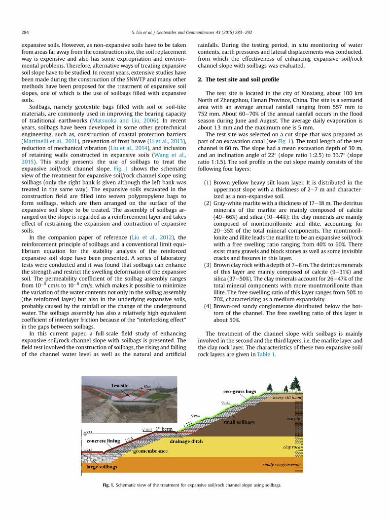
Soilbags, namely geotextile bags filled with soil or soil-likematerials, are commonly used in improving the bearing capacityof traditional earthworks (Matsuoka and Liu, 2006). In recentyears, soilbags have been developed in some other geotechnicalengineering, such as, construction of coastal protection barriers(Martinelli et al., 2011), prevention of frost heave (Li et al., 2013),reduction of mechanical vibration (Liu et al., 2014), and inclusionof retaining walls constructed in expansive soils (Wang et al.,2015). This study presents the use of soilbags to treat theexpansive soil/rock channel slope. Fig. 1 shows the schematicview of the treatment for expansive soil/rock channel slope usingsoilbags (only the right bank is given although the left bank wastreated in the same way). The expansive soils excavated in theconstruction field are filled into woven polypropylene bags toform soilbags, which are then arranged on the surface of theexpansive soil slope to be treated. The assembly of soilbags ar-ranged on the slope is regarded as a reinforcement layer and takeseffect of restraining the expansion and contraction of expansivesoils.
In the companion paper of reference (Liu et al., 2012), thereinforcement principle of soilbags and a conventional limit equi-librium equation for the stability analysis of the reinforcedexpansive soil slope have been presented. A series of laboratorytests were conducted and it was found that soilbags can enhancethe strength and restrict the swelling deformation of the expansivesoil. The permeability coefficient of the soilbag assembly rangesfrom 10�5 cm/s to 10�6 cm/s, which makes it possible to minimizethe variation of the water contents not only in the soilbag assembly(the reinforced layer) but also in the underlying expansive soils,probably caused by the rainfall or the change of the undergroundwater. The soilbags assembly has also a relatively high equivalentcoefficient of interlayer friction because of the “interlocking effect”in the gaps between soilbags.
In this current paper, a full-scale field study of enhancingexpansive soil/rock channel slope with soilbags is presented. Thefield test involved the construction of soilbags, the rising and fallingof the channel water level as well as the natural and artificial
Fig. 1. Schematic view of the treatment for expa
rainfalls. During the testing period, in situ monitoring of watercontents, earth pressures and lateral displacements was conducted,from which the effectiveness of enhancing expansive soil/rockchannel slope with soilbags was evaluated.
2. The test site and soil profile
The test site is located in the city of Xinxiang, about 100 kmNorth of Zhengzhou, Henan Province, China. The site is a semiaridarea with an average annual rainfall ranging from 557 mm to752 mm. About 60e70% of the annual rainfall occurs in the floodseason during June and August. The average daily evaporation isabout 1.3 mm and the maximum one is 5 mm.
The test site was selected on a cut slope that was prepared aspart of an excavation canal (see Fig. 1). The total length of the testchannel is 60 m. The slope had a mean excavation depth of 30 m,and an inclination angle of 22� (slope ratio 1:2.5) to 33.7� (sloperatio 1:1.5). The soil profile in the cut slope mainly consists of thefollowing four layers:
(1) Brown-yellow heavy silt loam layer. It is distributed in theuppermost slope with a thickness of 2e7 m and character-ized as a non-expansive soil.
(2) Gray-white marlite with a thickness of 17e18m. The detritusminerals of the marlite are mainly composed of calcite(49e66%) and silica (10e44%); the clay minerals are mainlycomposed of montmorillonite and illite, accounting for20e35% of the total mineral components. The montmoril-lonite and illite leads the marlite to be an expansive soil/rockwith a free swelling ratio ranging from 40% to 60%. Thereexist many gravels and block stones as well as some invisiblecracks and fissures in this layer.
(3) Brown clay rockwith a depth of 7e8m. The detritus mineralsof this layer are mainly composed of calcite (9e31%) andsilica (37e50%). The clay minerals account for 26e47% of thetotal mineral components with more montmorillonite thanillite. The free swelling ratio of this layer ranges from 50% to70%, characterizing as a medium expansivity.
(4) Brown-red sandy conglomerate distributed below the bot-tom of the channel. The free swelling ratio of this layer isabout 50%.
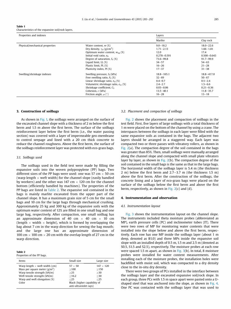
The treatment of the channel slope with soilbags is mainlyinvolved in the second and the third layers, i.e. themarlite layer andthe clay rock layer. The characteristics of these two expansive soil/rock layers are given in Table 1.
nsive soil/rock channel slope using soilbags.
Table 1Characteristics of the expansive soil/rock layers.
Properties and indexes Layers
Marlite Clay rock
Physical/mechanical properties Water content, w (%) 9.0e18.2 18.0e22.6Dry density, gd (g/cm3) 1.71e2.13 1.66e1.81Optimum water content, wop (%) 12.0 17.4Initial void ratio, e0 0.278e0.591 0.500e0.643Degree of saturation, Sr (%) 73.6e99.8 91.7e99.9Liquid limit, LL (%) 34e57 54e63Plastic limit, PL (%) 16e26 21e28Plasticity index, PI (%) 17e37 31e38
S. Liu et al. / Geotextiles and Geomembranes 43 (2015) 283e292 285
3. Construction of soilbags
As shown in Fig. 1, the soilbags were arranged on the surface ofthe excavated channel slope with a thickness of 2 m below the firstberm and 1.5 m above the first berm. The surface of the soilbagsreinforcement layer below the first berm (i.e., the water passingsection) was covered with a layer of impermeable geo-membraneto control seepage and lined with a 20 cm thick concrete toreduce the channel roughness. Above the first berm, the surface ofthe soilbags reinforcement layer was protectedwith eco-grass bags.
3.1. Soilbags used
The soilbags used in the field test were made by filling theexpansive soils into the woven polypropylene (PP) bags. Twodifferent sizes of the PP bags were used: one was 57 cm � 50 cm(warp length � weft width) for the channel slope (easily handledby workers) and the other was 147 cm � 120 cm for the channelbottom (efficiently handled by machines). The properties of thePP bags are listed in Table 2. The expansive soil contained in thebags is mainly marlite excavated from the upper part of thechannel slope. It has a maximum grain size of 5 cm for the smallbags and 10 cm for the large bags through mechanical crushing.Approximately 25 kg and 300 kg of the expansive soils with theoptimumwater content of 12% are filled in one small bag and onelarge bag, respectively. After compaction, one small soilbag hasan approximate dimension of 40 cm � 40 cm � 10 cm(length � width � height), which is formed by overlapping thebag about 7 cm in the warp direction for sewing the bag mouth;and the large one has an approximate dimension of100 cm � 100 cm � 20 cmwith the overlap length of 27 cm in thewarp direction.
Table 2Properties of the PP bags.
Items Small size Large size
Warp length � weft width (cm) 57 � 50 147 � 120Mass per square meter (g/m2) �100 �150Warp tensile strength (kN/m) �25 �30Weft tensile strength (kN/m) �16.2 �30Warp and weft elongation (%) �25 �25Color Black (higher capability of
anti-ultraviolet rays)
3.2. Placement and compaction of soilbags
Fig. 2 shows the placement and compaction of soilbags in thetest field. First, five layers of large soilbags with a total thickness of1 mwere placed on the bottom of the channel by using a crane. Theinterspaces between the soilbags in each layer were filled with thesame expansive soils as contained in the bags. The adjacent twolayers should be arranged in a staggered way. Each layer wascompacted two or three passes with vibratory rollers, as shown inFig. 2(a). The compaction degree of the soil contained in the bagswas greater than 85%. Then, small soilbags were manually arrangedalong the channel slope and compacted with small plate vibratorslayer by layer, as shown in Fig. 2(b). The compaction degree of thesoil contained in the small bags is the same as that in the large bags.The horizontal width of the soilbags layer is 5.4 m (the thickness2 m) below the first berm and 2.7e3.7 m (the thickness 1.5 m)above the first berm. After the construction of the soilbags, theconcrete lining and a layer of eco-grass bags were placed on thesurface of the soilbags below the first berm and above the firstberm, respectively, as shown in Fig. 2(c) and (d).
4. Instrumentation and observation
4.1. Instrumentation layout
Fig. 3 shows the instrumentation layout on the channel slope.The instruments included theta moisture probes (abbreviated asMP), earth pressure cells (PC) and inclinometer tubes (IT). Therewere two rows of MP for monitoring water contents that wereinstalled into the slope below and above the first berm, respec-tively. Each row has one MP inside the soilbags layer (about 1 mdeep, denoted as B1.0) and three MPs inside the expansive soilslope with an installed depth of 0.5 m, 1.5 m and 2.5 m (denoted asS0.5, S1.5 and S2.5), respectively. The moisture probes at each rowwere spaced 1.5 m apart, as shown in Fig. 3(b). In total, 8 moistureprobes were installed for water content measurements. Afterinstalling each of the moisture probes, the installation holes werebackfilled with moist soil, which was compacted to a dry densityclose to the in-situ dry density.
There were two groups of PCs installed in the interface betweenthe soilbags layer and the excavated expansive soil/rock slope. Ineach group, three PCs with 1.5 m space apart were pasted onto a U-shaped steel that was anchored into the slope, as shown in Fig. 4.One PC was contacted with the soilbags layer that was used to
Fig. 2. Photos of soilbags construction: (a) Compaction of large soilbags on the channel bottom; (b) Construction of soilbags on the channel slope; (c) Eco-grass bags above the firstberm; (d) Construction completion.
S. Liu et al. / Geotextiles and Geomembranes 43 (2015) 283e292286
measure the overburden pressure; the other two PCs on theopposite face of the U-shaped steel were intended to measure theswelling pressure of the expansive soil/rock as the U-shaped steelwas anchored into the slope. The U-shaped steel was parallelly
Fig. 3. Instrumentation layout on the channel
close to the row of the MPs so that the connectionwires of both theMPs and the PCs can be drawn out through an outlet tube, as shownin Fig. 3(a). The data from the MPs and the PCs were collected usinga data logger.
slope: (a) Cross section; (b) Vertical view.
Fig. 4. Schematic layout of earth pressure cell (PC).
S. Liu et al. / Geotextiles and Geomembranes 43 (2015) 283e292 287
Moreover, as illustrated in Fig. 3, two 10 m and 19 m longinclinometer tubes were installed into the first berm and the thirdberm, respectively, which were used to measure the lateral dis-placements of the tested expansive soil/rock slope.
4.2. Observation record
The observation record period in the test site lasted for morethan two years (i.e., from January, 2008 toMay, 2010), during whichtime it experienced the construction of the soilbags, the rising andfalling of the channel water level as well as the natural and artificialrainfalls.
The soilbags below the first berm were constructed from April27 to May 30, 2008, whose surfaces were lined with concretefrom June 2 to 12, 2008. The soilbags between the first and thesecond berms were constructed from June 17 to 27, 2008. The
Fig. 5. Changes of volumetric water contents during the constructio
construction of soilbags above the 2nd berm was from Aug. 5 toSept. 3, 2008.
Two rising and falling processes of the channel water level weresimulated: 1) rising from EL.92.7 m to EL.94.7 m during Oct. 23e25,2008 and further to EL.99.7 m during Dec. 3e8, 2008; 2) fallingfrom EL.99.7 m to EL.97.7 m during April 5e9, 2009 and further toEL.92.7 m during Nov. 29 to Dec. 22, 2009.
During the construction period of the soilbags and the concretelining, the test site experienced four relatively larger rainfalls with atotal precipitation of 15e30 mm each time. After the construction,one heavy rainfall with a total precipitation as high as 90 mm wasrecorded on July 14, 2008, and a 22 mm rainfall was recorded onAug.13, 2008. During the period of Aug.13, 2008 to Jan. 26, 2009, nonatural precipitation occurred and the test site was subjected to acontinuous drought. To further investigate the effect of the soilbagslayer, the artificial rainfalls with a mean intensity of about 50 mm/d were simulated during Mar. 9e20, 2009. After then, some sub-sequent small natural rainfalls were observed.
5. Results and discussions
5.1. Water content
Fig. 5 shows the changes of volumetric water contents inside theexpansive soil/rock slope from April to June, 2008. During thisperiod, the soilbags and the concrete lining below the first bermwere under construction, and the testing site experienced four
n: (a) Below the first berm (R1); (b) Above the first berm (R2).
S. Liu et al. / Geotextiles and Geomembranes 43 (2015) 283e292288
rainfalls. It was observed that the rainfalls caused a significant in-crease and then a prompt decrease in the volumetric water con-tents of the expansive soil/rock slope within the depth of 1.5 m(measured by the MP-S0.5 and MP-S1.5). However, the increase inthe volumetric water content below 1.5 mwas not so significant, asmeasured by the MP-S2.5. Moreover, the delayed response of thevolumetric water content to the rainfalls was observed. In anothertest conducted by Zhan et al. (2007) in SNWTP, a significant in-crease of the water content was also observed within the top 1.5 mof the bare expansive soil slope, which may be due to the somedeep, extended open cracks at the upper part of the slope. Beforesoilbags were placed, the expansive soil/rock slope within a depthof approximate 1.5m, the so-called atmospheric influence region, isinfluenced significantly by rainfalls.
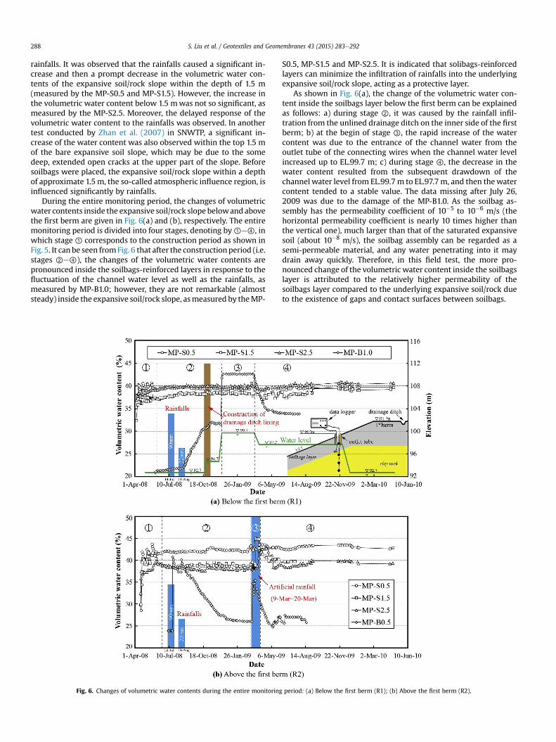
During the entire monitoring period, the changes of volumetricwater contents inside the expansive soil/rock slope belowand abovethe first berm are given in Fig. 6(a) and (b), respectively. The entiremonitoring period is divided into four stages, denoting by①e④, inwhich stage ① corresponds to the construction period as shown inFig. 5. It can be seen fromFig. 6 that after the constructionperiod (i.e.stages ②e④), the changes of the volumetric water contents arepronounced inside the soilbags-reinforced layers in response to thefluctuation of the channel water level as well as the rainfalls, asmeasured by MP-B1.0; however, they are not remarkable (almoststeady) inside the expansive soil/rock slope, asmeasured by theMP-
Fig. 6. Changes of volumetric water contents during the entire monitoring
S0.5, MP-S1.5 and MP-S2.5. It is indicated that solibags-reinforcedlayers can minimize the infiltration of rainfalls into the underlyingexpansive soil/rock slope, acting as a protective layer.
As shown in Fig. 6(a), the change of the volumetric water con-tent inside the soilbags layer below the first berm can be explainedas follows: a) during stage ②, it was caused by the rainfall infil-tration from the unlined drainage ditch on the inner side of the firstberm; b) at the begin of stage ③, the rapid increase of the watercontent was due to the entrance of the channel water from theoutlet tube of the connecting wires when the channel water levelincreased up to EL.99.7 m; c) during stage ④, the decrease in thewater content resulted from the subsequent drawdown of thechannel water level from EL.99.7m to EL.97.7 m, and then thewatercontent tended to a stable value. The data missing after July 26,2009 was due to the damage of the MP-B1.0. As the soilbag as-sembly has the permeability coefficient of 10�5 to 10�6 m/s (thehorizontal permeability coefficient is nearly 10 times higher thanthe vertical one), much larger than that of the saturated expansivesoil (about 10�8 m/s), the soilbag assembly can be regarded as asemi-permeable material, and any water penetrating into it maydrain away quickly. Therefore, in this field test, the more pro-nounced change of the volumetric water content inside the soilbagslayer is attributed to the relatively higher permeability of thesoilbags layer compared to the underlying expansive soil/rock dueto the existence of gaps and contact surfaces between soilbags.
period: (a) Below the first berm (R1); (b) Above the first berm (R2).
S. Liu et al. / Geotextiles and Geomembranes 43 (2015) 283e292 289
As the slope above the first berm is protected with permeableeco-soilbags, the changes of the volumetric water contents inresponse to the rainfalls and evaporation above the first berm arerelatively more significant than those below the first berm, espe-cially inside the soilbags layer. During stage ②, the slope experi-enced one heavy rainfall with a total precipitation as high as 90mm(July 14, 2008), Fig. 6(b) shows that the volumetric water contentinside the soilbags layer increased rapidly from 24% to 41%, thendecreased to 37.5% due to the evaporation and infiltration, andagain increased to 40% due to the 22 mm rainfall on Aug. 13, 2008.From Aug. 13, 2008 to Jan. 26, 2009, the continuous drought in thetest site caused the decrease of the volumetric water content insidethe soilbags layer from 40% to 26%, but the water contents insidethe expansive soil/rock slope remained nearly steady, indicatingthe good water retention ability of the soilbag assembly layer forthe underlying expensive soil/rock slope in an arid climate condi-tion. During Mar. 9 to Mar. 20, 2009, the artificial rainfalls with amean intensity of about 50 mm/d were simulated to furtherinvestigate the effect of the soilbags layer. It can be seen fromFig. 6(b) that during the artificial rainfalls (stage ③), the changes ofthe volumetric water content inside the soilbags layer are moresignificant than those inside the underlying expansive soil/rockslope, as measured by MP-B0.5, MP-S0.5, MP-S1.5 and MP-S2.5. Itwas attributed to the relatively high permeability of the soilbagsassembly, especially along the horizontal inter-layers. Thus, thesoilbag assembly has an effect of reducing the infiltration of rain-falls into the underlying expansive soil/rock slope. After the artifi-cial rainfalls (stage ④), the water content inside the soilbags layerdecreased gradually and tended to a stable value although therewas some slight fluctuation due to some small natural rainfalls. Thesubsequent missing data of MP-B0.5 and MP-S1.5 were due to thedamage of the sensors.
5.2. Earth pressure
Fig. 7 shows the measured earth pressures inside the soilbagslayer and the underlying expansive soil/rock slope. As stated pre-viously, the PC-U on the upper side of the U-shaped steel was usedtomeasure the overburden pressure of the soilbags layer, while thePC-D1 and PC-D2 on the opposite face of the U-shaped steel weredesigned to approximately measure the swelling pressures of theunderlying expansive soil/rocks. The changes of the measuredearth pressures may also be analyzed in four stages, in which stage① refers to the period before the completion of the soilbags layerconstruction. Before the construction of the soilbags layer, nooverburden pressure was measured by the PC-U, and themaximum swelling pressures due to rainfalls, measured by the PC-D1 and PC-D2, were averagely about 26.3 kPa and 14.5 kPa belowand above the first berm, respectively. During the construction ofthe soilbags layer, the measurement values of the three PCsincreased greatly due to the influence of the construction ma-chines and compaction, as shown in Fig. 7(c) and (d). After thecompletion of the soilbags layer construction, the values measuredby the PCs decreased gradually. During stage ②, as shown inFig. 7(a) and (b), the values measured by the PC-U tended to theoverburden pressures of 30 kPa of the 2 m thick soilbags layerbelow the first berm and 22.5 kPa of the 1.5 m thick soilbags layerabove the first berm. The average values measured by the PC-D1and PC-D2 below and above the first berm were 54.2 kPa and28.4 kPa, respectively, nearly the swelling pressures of clay rockand marlite at the moisture and density of the site measured byYangtze River Scientific Research Institute (2010). Below the firstberm, the channel water level increased up to 99.7 m and thewater flowed into the outlet tube of the connecting wires duringstage ③. The wetting-induced weight increase of the soilbags led
to the increase of the overburden pressure by about 8.7 kPa, asshown in Fig. 7(a). Above the first berm, an artificial rainfall wasproduced, resulting in the increases of the overburden pressureand the swelling pressure during stage ③, as shown in Fig. 7(b).However, the increase of the overburden pressure induced by theweight increase of the soilbags is more prominent than the in-crease of the swelling pressure of the expansive soil/rock causedby the limited infiltration of the artificial rainfall. During stage ④,the measurement values of the PCs approached to those asmeasured at the end of stage ②, although there were some smallvariations caused by natural rainfalls.
As aforementioned, the measurement by the PC-D1 and PC-D2is approximately the swelling pressure in the underlying expan-sive soil/rock slope. The comparison of Fig. 6 with Fig. 7 indicatesthat the swelling pressure is inter-linked with the water contentmeasured nearby (MP-S0.5) after the completion of the soilbagslayer construction. During that period, as a result of the protectionof the soilbags layer, the changes of both the measured watercontent and the swelling pressure are small in the underlyingexpansive soil/rock slope. During stage ③ above the first berm, theincrease of the water content caused by the infiltration of theartificial rainfall leads to the increase in the swelling pressure.However, it is noticed that this inter-linked relationship is notobvious in the soilbags-reinforced layer because the swellingdeformation of expansive soils is restrained by the bags and thesoilbags layer is equivalent to a non-expansive layer. The reducedswelling of the expansive soil was attributed to the tensile forces Talong the perimeters of the bags, which developed due to theextension of the bag under the heaving deformation action occur-ring during the wetting process, which is also validated in a modeltest by Wang et al. (2015).
5.3. Lateral displacement
Fig. 8 gives the distributions of the lateral displacements alongthe slope depth, measured by IT-1 and IT-2 that were installed inthe outer side of the first berm and the third berm, respectively. Thepositive value denotes the lateral displacement toward the channel.The maximum lateral displacements measured by IT-1 and IT-2 are25.5 mm and 15 mm, respectively. The relatively large lateral dis-placements measured by IT-1 are within the soilbags layer (aboveEL.99.7 m), and those measured by IT-2 are within the slope depthbetween EL.104 m and EL.113.7 m. In Fig. 8(a), the smaller lateraldisplacements at the topmost than those at the subsequent shallowdepth (EL.101.2 m) may result from the restraint of the concretelining. The similar phenomena observed by IT-2 in May 8 and July25, 2009, as shown in Fig. 8(b), may be attributed to the shrinkageof the expansive soils contained in the surface soilbags.
Fig. 9 shows the evolutions of the lateral displacementsmeasured at some typical elevations. It is seen from Fig. 9(a) thatthe evolutions of the lateral displacements measured at the threedifferent elevations are almost the same, but the magnitudes atEL.101.2 m are much greater than those at EL.99.7 m and EL.96.7 m.Before November, 2008, the increase in the lateral displacements(aeb in Fig. 9(a)) was mainly caused by the construction machinesrunning at the first berm, the rainfall infiltration from the slopesurface and the unlined drainage ditch at the inner side of the firstberm; impounding of the channel water up to EL.99.7 m caused aslight decrease (about 4 mm, ced in Fig. 9(a)) in the lateraldisplacement (backward the slope); Subsequently, as the outlettube of the connecting wires at EL.99.7 m was not well sealed, thechannel water entered into the soilbags layer from the outlet tube.As a result, the interface friction between the wetting soilbagsdecreased and thereby the lateral displacement increased (eef inFig. 9(a)). When the channel water level fell from EL.99.7 m to
Fig. 7. Changes of earth pressures measured by PCs: (a) Below the first berm (R1); (b) Above the first berm (R2); (c) Stage ① below the first berm; (d) Stage ① above the first berm.
S. Liu et al. / Geotextiles and Geomembranes 43 (2015) 283e292290
EL.97.7 m, the water inside the soilbags layer drained gradually andthe lateral displacement recovered under the action of the channelwater pressure at EL.97.7 m and tended to a relative stable value(fegeh in Fig. 9(a)).
The soilbags above the second berm were constructed duringAugust 5 and September 3, 2008. Before August 5, 2008, thelateral displacements measured by IT-2 were mainly caused bythe excavation unloading and the rainfall infiltration into the bareexpansive soil/rock slope. After the completion of the soilbagsconstruction, the lateral displacements measured by IT-2 at thefour different elevations changed slightly even during the artifi-cial rainfalls, as shown in Fig. 9(b). The effectiveness of the
soilbags on the stability of the expansive soil/rock slope was thusindicated.
6. Conclusions
A full-scale field study of treatment for expansive soil/rockchannel slope with soilbags was conducted to investigate the in-fluence of soilbags construction, variation of channel water leveland rainfalls on the changes of water content, earth pressure andlateral displacement in the soilbags layer and the underlyingexpansive soil/rock slope. Based on the field monitored results, thefollowing conclusions can be obtained:
Fig. 8. Distributions of lateral displacements of the slope along the depth: (a) Measured by IT-1; (b) Measured by IT-2.
S. Liu et al. / Geotextiles and Geomembranes 43 (2015) 283e292 291
(1) The water content in the bare expansive soil/rock channelslope was significantly affected by rainfalls and evaporation.After the completion of soilbags construction, the watercontent inside the soilbags layer exhibited certain changeswith the variation of the channel water level and rainfalls,but it was almost unchanged inside the underlying expansive
Fig. 9. Evolutions of lateral displacements of the slope at some typical elevations: (a) At EL.1
soil/rock slope. These results indicated that the soilbags layercan effectively retard the moisture movement into the un-derlying expansive soil/rock slope.
(2) The earth pressures measured in the interface between thesoilbags layer and the expansive soil/rock slope were greatlyaffected by the construction of soilbags. After the completion
01.2 m, 99.7 m and 96.7 m (IT-1); (b) At EL.113.1 m, 111.1 m, 107.1 m and 101.1 m (IT-2).
S. Liu et al. / Geotextiles and Geomembranes 43 (2015) 283e292292
of the soilbags layer construction, the earth pressuresmeasured inside the expansive soil/rock slope nearly tendedto the swelling pressures of the expansive soil/rock and thosemeasured under the soilbags layer were close to the over-burden pressures of the soilbags layer. This measurementsuggests that the soilbags layer acts as a non swelling rein-forcement layer, and presses the underlying expansive soil/rock slope.
(3) The lateral displacements of the expansive soil/rock channelslope were mainly caused by the slope excavation unloadingand the soilbags construction. After the completion of soil-bags construction, they changed slightly even though thechannel slope was subjected to rainfalls.
Acknowledgments
The authors would like to acknowledge the constructive sug-gestion and the great help from Yisen Wang. This work was sup-ported by the National Natural Science Foundation of China(51379066) and the Key Projects in the National Science andTechnology Pillar Program during the 11th 5-year Plan Period of PRChina (Grant No. 2006 BAB04A10). It was also a part of work in theproject funded by the Priority Academic Program Development ofJiangsu Higher Education Institutions (PAPD) (Grant No. YS11001).These supports are gratefully acknowledged. The authors alsoappreciate the assessors' excellent comments and constructivesuggestions to the study.
References
Al-Omari, R.R., Hamodi, F.J., 1991. Swelling resistant geogrid e a new approach forthe treatment of expansive soils. Geotext. Geomembr. 10 (4), 295e317.
Aytekin, M., 1997. Numerical modeling of EPS geofoam used with swelling soil.Geotext. Geomembr. 15 (1), 133e146.
Al-Rawas, A.A., Hago, A.W., Al-Sarmi, H., 2005. Effect of lime, cement and Sarooj(artificial pozzolan) on the swelling potential of an expansive soil from Oman.Build. Environ. 40 (5), 681e687.
Bouazza, A., Singh, R.M., Rowe, R.K., Gassner, F., 2014. Heat and moisture migrationin a geomembraneeGCL composite liner subjected to high temperatures andlow vertical stresses. Geotext. Geomembr. 42 (5), 555e563.
Chen, F.H., 1988. Foundation on Expansive Soils. Elsevier, Amsterdam, Netherlands.Cokca, E., 2001. Use of class C fly ashes for the stabilization of an expansive soil.
J. Geotech. Geoenviron. Eng. 127 (7), 568e573.Calik, U., Sadoglu, E., 2014. Classification, shear strength, and durability of expansive
clayey soil stabilized with lime and perlite. Nat. Hazards 71 (3), 1289e1303.Desai, I.D., Oza, B.N., 1977. Influence of anhydrous calcium chloride on the shear
strength of expansive soil. In: Proc. of the 1st National Symposium on Expan-sive Soils, HBTI-Kanpur, India, pp. 4-1e4-5.
Dif, A.E., Bluemel, W.F., 1991. Expansive soils under cyclic drying and wetting.Geotech. Test. J. 14 (1), 96e102.
Estabragh, A.R., Rafatjo, H., Javadi, A.A., 2014. Treatment of an expansive soil bymechanical and chemical techniques. Geosynth. Int. 21 (3), 233e243.
Heibaum, M., 2014. Geosynthetics for waterways and flood protection structures econtrolling the interaction of water and soil. Geotext. Geomembr. 42 (4),374e393.
Ikizler, S.B., Aytekin, M., Nas, E., 2008. Laboratory study of expanded polystyrene(EPS) geofoam used with expansive soils. Geotext. Geomembr. 26 (2), 189e195.
Ikizler, S.B., Aytekin, M., Vekli, M., 2009. Reductions in swelling pressure ofexpansive soil stabilized using EPS geofoam and sand. Geosynth. Int. 16 (3),216e221.
Ito, M., Azam, S., 2010. Determination of swelling and shrinkage properties of un-disturbed expansive soils. Geotech. Geol. Eng. 28, 413e422.
Katti, R.K., 1979. Search for solutions to problems in black cotton soils. IndianGeotech. J. 9 (1), 1e80.
Liu, S.H., Bai, F.Q., Wang, Y.S., Wang, S., Li, Z., 2012. Treatment for expansive soilchannel slope with soilbags. J. Aerosp. Eng. 26 (4), 657e666.
Li, X.W., Wang, Y., Yu, J.W., Wang, Y.L., 2012. Unsaturated expansive soil fissurecharacteristics combined with engineering behaviors. J. Cent. South Univ. 19,3564e3571.
Li, Z., Liu, S.H., Wang, L.J., Zhang, C.C., 2013. Experimental study on the effect of frostheave prevention using soilbags. Cold Regions Sci. Technol. 85, 109e116.
Liu, S.H., Gao, J.J., Wang, Y.Q., Weng, L.P., 2014. Experimental study on vibrationreduction by using soilbags. Geotext. Geomembr. 42 (1), 52e62.
Matsuoka, H., Liu, S.H., 2006. A New Earth Reinforcement Method Using Soilbags.Taylor & Francis/Balkema, The Netherlands.
Madhyannapu, R.S., Puppala, A.J., Nazarian, S., Yuan, D., 2009. Quality assessmentand quality control of deep soil mixing construction for stabilizing expansivesubsoils. J. Geotech. Geoenviron. Eng. 136 (1), 119e128.
Martinelli, M., Zanuttigh, B., Nigris, N.D., Preti, M., 2011. Sand bag barriers for coastalprotection along the Emilia Romagna littoral, Northern Adriatic Sea, Italy.Geotext. Geomembr. 29 (4), 370e380.
Madhyannapu, R.S., Puppala, A.J., 2014. Design and construction guidelines for deepsoil mixing to stabilize expansive soils. J. Geotech. Geoenviron. Eng. 140 (9),1e15.
Satyanarayana, B., 1969. Behavior of expansive soil treated or cushioned with sand.In: Proceedings of 2nd International Conference on Expansive Soils, Texas,pp. 308e316.
Sharma, R.S., Phanikumar, B.R., Rao, B.V., 2008. Engineering behavior of a remoldedexpansive clay blended with lime, calcium chloride, and rice-husk ash. J. Mater.Civ. Eng. 20 (8), 509e515.
Safari, E., Jalili Ghazizade, M., Abduli, M.A., Gatmiri, B., 2014. Variation of crackintensity factor in three compacted clay liners exposed to annual cycle of at-mospheric conditions with and without geotextile cover. Waste Manag. 34,1408e1415.
Trouzine, H., Bekhiti, M., Asroun, A., 2012. Effects of scrap tyre rubber fibre onswelling behaviour of two clayey soils in Algeria. Geosynth. Int. 19 (2), 124e132.
Viswanadham, B.V.S., Phanikumar, B.R., Mukherjee, R.V., 2009b. Effect of poly-propylene tape fibre reinforcement on swelling behaviour of an expansive soil.Geosynth. Int. 16 (5), 393e401.
Wang, L.J., Liu, S.H., Zhou, B., 2015. Experimental study on the inclusion of soilbagsin retaining walls constructed in expansive soils. Geotext. Geomembr. 43 (1),89e96.
Yangtze River Scientific Research Institute, 2010. Research Report on FailureMechanism and Treatment Technology for Expansive Soil Channel Slope(Wuhan, China).
Zhan, T.L., Ng, C.W.W., Fredlund, D.G., 2007. Field study of rainfall infiltration into agrassed unsaturated expansive soil slope. Can. Geotech. J. 44 (4), 392e408.
Zemenu, G., Martine, A., Roger, C., 2009. Analysis of the behaviour of a naturalexpansive soil under cyclic drying and wetting. Bull. Eng. Geol. Environ. 68 (3),421e436.