RIVISTA ITALIANA DI GEOTECNICA 1/2010 Field tests on effect of concrete age on pile integrity testing Johann Brückl, Xue-Tao Wang, Wei Wu* Summary This article reports on a series of integrity tests on four bored piles in a construction site near Vienna. The aim of these tests is to investigate the effect of concrete age on pile integrity tests. Extensive field tests were carried out within the 156 days after pile installation. The field tests were supplemented by laboratory tests (ultrasound measurements and compres- sion tests) on core samples from bored piles. Based on the test results, some recommendations are made for the practice. 1. Introduction Bored piles are widely used in foundation engi- neering. The prediction of the behaviour of bored piles requires both engineering knowledge and practical experience. The behaviour of foundation piles is affected by several factors, which are difficult to quantify, such as the installation methods, rate of installation and workmanship. The bearing capacity of piles depends not only on the physical properties of piles and soil conditions but also on the method of construction. Better knowledge of the soil behav- iour and higher construction quality give rise to bet- ter design and increase the higher vertical and hor- izontal bearing capacity of piles. This in turn im- plies an increased demand on the material quality and workmanship. The quality control of bored piles has increasingly gained importance. The integrity test, also called sonic integrity test (SIT), is a non-destructive testing method that can indicate anomalies in piles such as major cracks, necking, soil inclusions or voids, which may have negative impact on strength behaviour of piles [FINNO and GASSMAN, 1996; KIRSCH and KLING- MÜLLER, 2003; MIDDENDORP and VERBEEK, 2006]. Pile integrity testing can provide valuable information on the integrity of the pile shaft and therefore en- sure the quality of pile construction. The integrity tests are usually carried out on matured concrete be- fore construction of the superstructure. In practice, integrity tests are sometimes carried out at early stage, e.g. 7 days after pile installation. Frequently, short construction time requires integrity testing at early concrete age. The properties of the concrete depend on the age which in turn influences the wave propagation characteristics. An estimation of the shaft length and the pile integrity are both depend- ent upon the wave propagation velocity in concrete [NIEDERLEITHINGER and TAFFE, 2006].This paper in- vestigates the effects of the concrete age on the re- sults of pile integrity testing. In addition, we look into the minimum time after placing concrete, when non-destructive testing methods can be reliably evaluated. 2. Testing method In the present investigation, field measurements of wave velocities were carried out on four installed bored piles with a length of about 13 m and a dia- meter of about 90 cm. Both the ground conditions and the pile installation were carefully documented. The field wave velocities were compared with the measurements in laboratory. Those laboratory measurements were performed on a concrete beam with an ultrasonic device. Moreover, some axial compression tests were carried out on cylindrical specimens obtained from bore cores of the test piles. 2.1. Field conditions For the purpose of field testing, four bored piles (without steel reinforcement) with a diameter of about 90 cm and length of 13 m were installed (Fig. 1). Before the integrity testing, the pile heads were cut by about 80 cm to remove the disturbed concrete. The field tests were carried out within a period of 156 days. The properties of the concrete material are given in table I. The pile length and di- ameter are selected so that the difference in com- pressive strength at measured level and at the pile tip is minimal. For this purpose the ratio of length to diameter of the pile is chosen to be about 14. The ground conditions are depicted in figure 2. The top layer consists of fine sand with a thickness of about 1.1 m. It is followed by a massive stratum of * Institut für Geotechnik, Universität für Bodenkultur (BOKU), Vienna, Austria
Transcript
RIVISTA ITALIANA DI GEOTECNICA 1/2010
Field tests on effect of concrete age on pile integrity testing
Johann Brückl, Xue-Tao Wang, Wei Wu*
SummaryThis article reports on a series of integrity tests on four bored piles in a construction site near Vienna. The aim of these
tests is to investigate the effect of concrete age on pile integrity tests. Extensive field tests were carried out within the 156days after pile installation. The field tests were supplemented by laboratory tests (ultrasound measurements and compres-sion tests) on core samples from bored piles. Based on the test results, some recommendations are made for the practice.
1. Introduction
Bored piles are widely used in foundation engi-neering. The prediction of the behaviour of boredpiles requires both engineering knowledge andpractical experience. The behaviour of foundationpiles is affected by several factors, which are difficultto quantify, such as the installation methods, rate ofinstallation and workmanship. The bearing capacityof piles depends not only on the physical propertiesof piles and soil conditions but also on the methodof construction. Better knowledge of the soil behav-iour and higher construction quality give rise to bet-ter design and increase the higher vertical and hor-izontal bearing capacity of piles. This in turn im-plies an increased demand on the material qualityand workmanship. The quality control of boredpiles has increasingly gained importance.
The integrity test, also called sonic integrity test(SIT), is a non-destructive testing method that canindicate anomalies in piles such as major cracks,necking, soil inclusions or voids, which may havenegative impact on strength behaviour of piles[FINNO and GASSMAN, 1996; KIRSCH and KLING-MÜLLER, 2003; MIDDENDORP and VERBEEK, 2006]. Pileintegrity testing can provide valuable informationon the integrity of the pile shaft and therefore en-sure the quality of pile construction. The integritytests are usually carried out on matured concrete be-fore construction of the superstructure. In practice,integrity tests are sometimes carried out at earlystage, e.g. 7 days after pile installation. Frequently,short construction time requires integrity testing atearly concrete age. The properties of the concretedepend on the age which in turn influences the wavepropagation characteristics. An estimation of theshaft length and the pile integrity are both depend-
ent upon the wave propagation velocity in concrete[NIEDERLEITHINGER and TAFFE, 2006].This paper in-vestigates the effects of the concrete age on the re-sults of pile integrity testing. In addition, we lookinto the minimum time after placing concrete, whennon-destructive testing methods can be reliablyevaluated.
2. Testing method
In the present investigation, field measurementsof wave velocities were carried out on four installedbored piles with a length of about 13 m and a dia-meter of about 90 cm. Both the ground conditionsand the pile installation were carefully documented.The field wave velocities were compared with themeasurements in laboratory. Those laboratorymeasurements were performed on a concrete beamwith an ultrasonic device. Moreover, some axialcompression tests were carried out on cylindricalspecimens obtained from bore cores of the test piles.
2.1. Field conditions
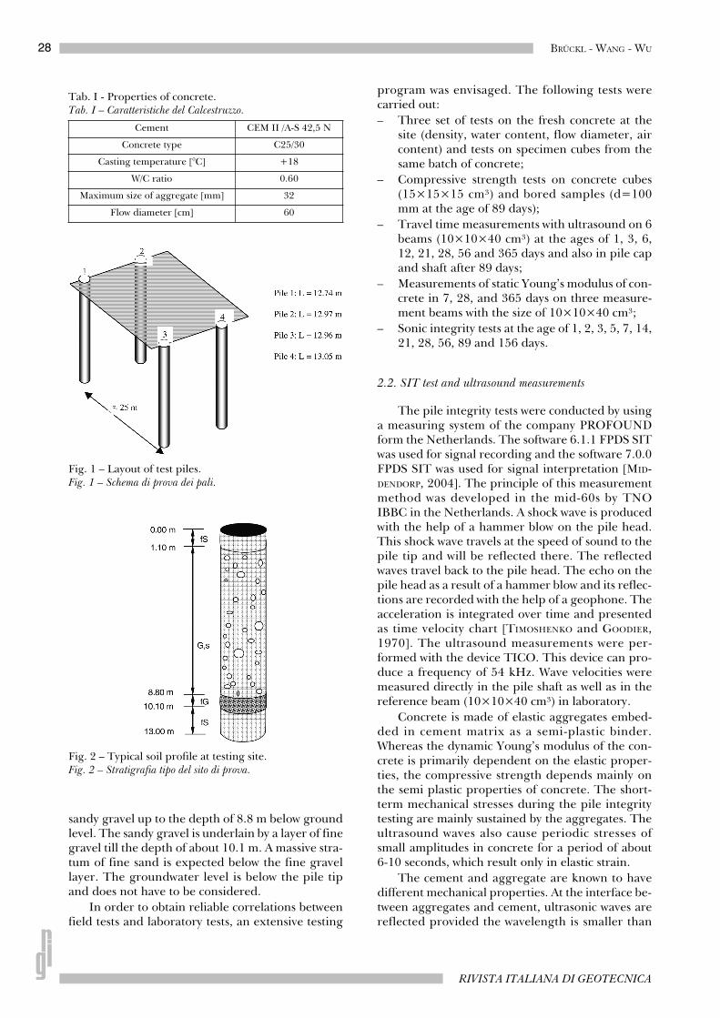
For the purpose of field testing, four bored piles(without steel reinforcement) with a diameter ofabout 90 cm and length of 13 m were installed(Fig. 1). Before the integrity testing, the pile headswere cut by about 80 cm to remove the disturbedconcrete. The field tests were carried out within aperiod of 156 days. The properties of the concretematerial are given in table I. The pile length and di-ameter are selected so that the difference in com-pressive strength at measured level and at the piletip is minimal. For this purpose the ratio of lengthto diameter of the pile is chosen to be about 14.
The ground conditions are depicted in figure 2.The top layer consists of fine sand with a thicknessof about 1.1 m. It is followed by a massive stratum of
* Institut für Geotechnik, Universität für Bodenkultur (BOKU), Vienna, Austria
28 BRÜCKL - WANG - WU
RIVISTA ITALIANA DI GEOTECNICA
sandy gravel up to the depth of 8.8 m below groundlevel. The sandy gravel is underlain by a layer of finegravel till the depth of about 10.1 m. A massive stra-tum of fine sand is expected below the fine gravellayer. The groundwater level is below the pile tipand does not have to be considered.
In order to obtain reliable correlations betweenfield tests and laboratory tests, an extensive testing
program was envisaged. The following tests werecarried out:– Three set of tests on the fresh concrete at the
site (density, water content, flow diameter, aircontent) and tests on specimen cubes from thesame batch of concrete;
– Compressive strength tests on concrete cubes(15×15×15 cm³) and bored samples (d=100mm at the age of 89 days);
– Travel time measurements with ultrasound on 6beams (10×10×40 cm³) at the ages of 1, 3, 6,12, 21, 28, 56 and 365 days and also in pile capand shaft after 89 days;
– Measurements of static Young’s modulus of con-crete in 7, 28, and 365 days on three measure-ment beams with the size of 10×10×40 cm³;
– Sonic integrity tests at the age of 1, 2, 3, 5, 7, 14,21, 28, 56, 89 and 156 days.
2.2. SIT test and ultrasound measurements
The pile integrity tests were conducted by usinga measuring system of the company PROFOUNDform the Netherlands. The software 6.1.1 FPDS SITwas used for signal recording and the software 7.0.0FPDS SIT was used for signal interpretation [MID-DENDORP, 2004]. The principle of this measurementmethod was developed in the mid-60s by TNOIBBC in the Netherlands. A shock wave is producedwith the help of a hammer blow on the pile head.This shock wave travels at the speed of sound to thepile tip and will be reflected there. The reflectedwaves travel back to the pile head. The echo on thepile head as a result of a hammer blow and its reflec-tions are recorded with the help of a geophone. Theacceleration is integrated over time and presentedas time velocity chart [TIMOSHENKO and GOODIER,1970]. The ultrasound measurements were per-formed with the device TICO. This device can pro-duce a frequency of 54 kHz. Wave velocities weremeasured directly in the pile shaft as well as in thereference beam (10×10×40 cm³) in laboratory.
Concrete is made of elastic aggregates embed-ded in cement matrix as a semi-plastic binder.Whereas the dynamic Young’s modulus of the con-crete is primarily dependent on the elastic proper-ties, the compressive strength depends mainly onthe semi plastic properties of concrete. The short-term mechanical stresses during the pile integritytesting are mainly sustained by the aggregates. Theultrasound waves also cause periodic stresses ofsmall amplitudes in concrete for a period of about6-10 seconds, which result only in elastic strain.
The cement and aggregate are known to havedifferent mechanical properties. At the interface be-tween aggregates and cement, ultrasonic waves arereflected provided the wavelength is smaller than
Tab. I - Properties of concrete.Tab. I – Caratteristiche del Calcestruzzo.
Cement CEM II /A-S 42,5 N
Concrete type C25/30
Casting temperature [°C] +18
W/C ratio 0.60
Maximum size of aggregate [mm] 32
Flow diameter [cm] 60
Fig. 1 – Layout of test piles.Fig. 1 – Schema di prova dei pali.
Fig. 2 – Typical soil profile at testing site.Fig. 2 – Stratigrafia tipo del sito di prova.
29FIELD TESTS ON EFFECT OF CONCRETE AGE ON PILE INTEGRITY TESTING
GENNAIO - MARZO 2010
the mean diameter of the aggregates. As for themeasurement of longitudinal waves, a frequency of54 kHz was selected. With this frequency it can beensured that inelasticity of concrete does not affectthe measurements. With an expected wave velocityof about 4000 m/s and a test frequency of 54 kHz, awave length well above the maximum size of aggre-gate can be obtained.
The sound wave for the integrity tests gives riseto deformation in both longitudinal and lateral di-rection. However, the signals in the lateral directionwere not measured. Note that the material particlesmove under the imparted stress with the particle ve-locity, which in contrast to the ultrasonic wave veloc-ity, is independent of the applied force.
3. Analysis and interpretation
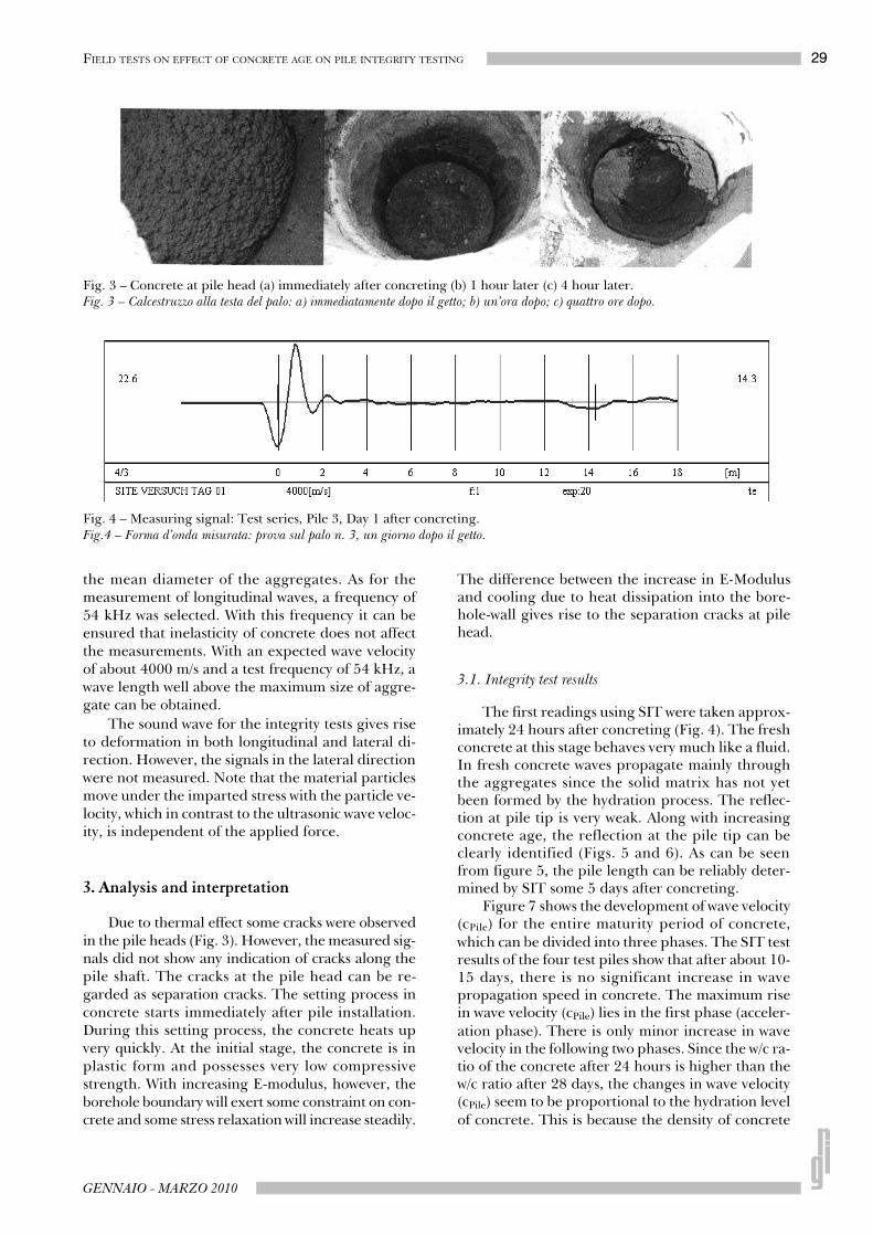
Due to thermal effect some cracks were observedin the pile heads (Fig. 3). However, the measured sig-nals did not show any indication of cracks along thepile shaft. The cracks at the pile head can be re-garded as separation cracks. The setting process inconcrete starts immediately after pile installation.During this setting process, the concrete heats upvery quickly. At the initial stage, the concrete is inplastic form and possesses very low compressivestrength. With increasing E-modulus, however, theborehole boundary will exert some constraint on con-crete and some stress relaxation will increase steadily.
The difference between the increase in E-Modulusand cooling due to heat dissipation into the bore-hole-wall gives rise to the separation cracks at pilehead.
3.1. Integrity test results
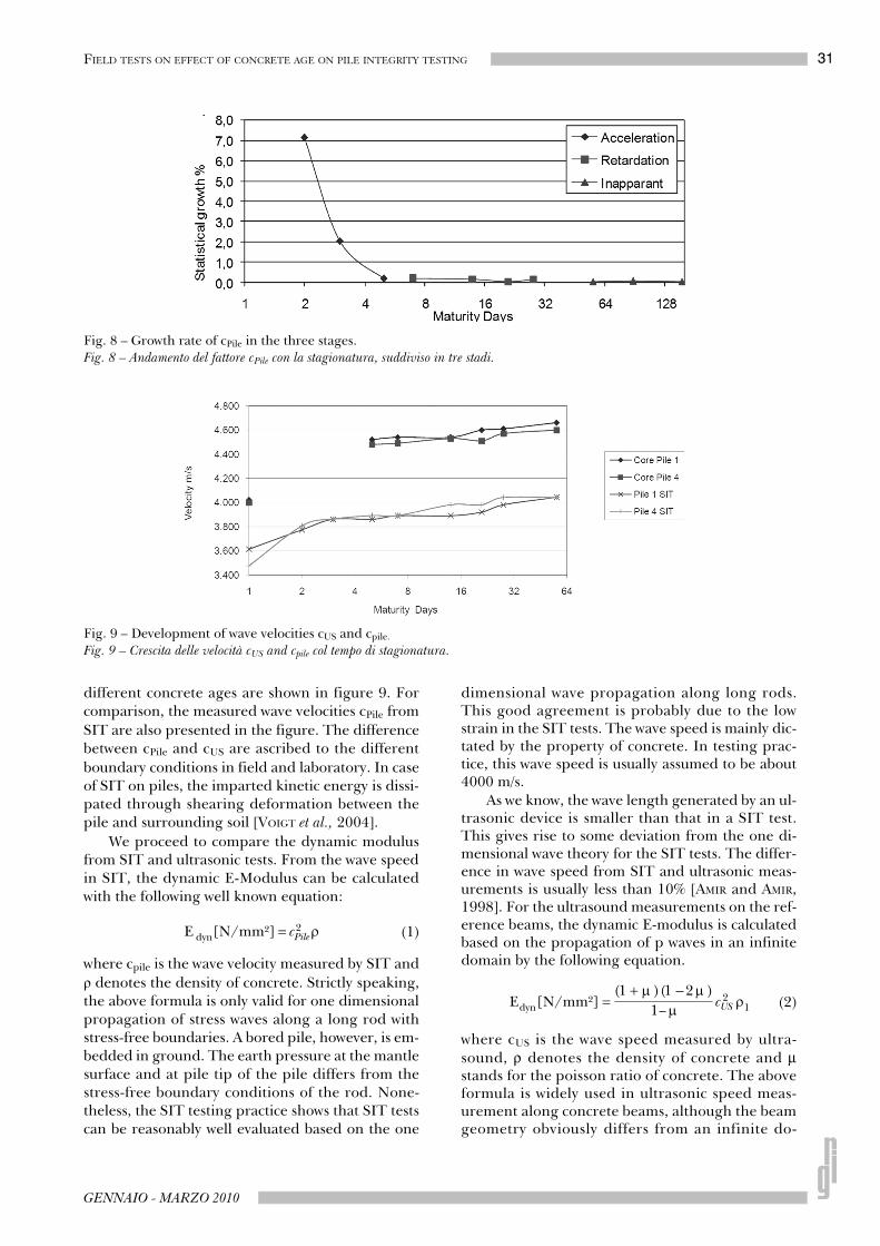
The first readings using SIT were taken approx-imately 24 hours after concreting (Fig. 4). The freshconcrete at this stage behaves very much like a fluid.In fresh concrete waves propagate mainly throughthe aggregates since the solid matrix has not yetbeen formed by the hydration process. The reflec-tion at pile tip is very weak. Along with increasingconcrete age, the reflection at the pile tip can beclearly identified (Figs. 5 and 6). As can be seenfrom figure 5, the pile length can be reliably deter-mined by SIT some 5 days after concreting.
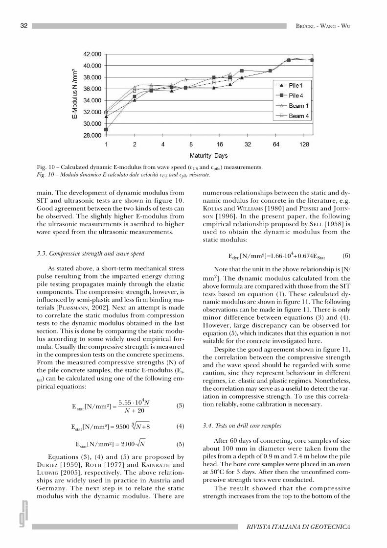
Figure 7 shows the development of wave velocity(cPile) for the entire maturity period of concrete,which can be divided into three phases. The SIT testresults of the four test piles show that after about 10-15 days, there is no significant increase in wavepropagation speed in concrete. The maximum risein wave velocity (cPile) lies in the first phase (acceler-ation phase). There is only minor increase in wavevelocity in the following two phases. Since the w/c ra-tio of the concrete after 24 hours is higher than thew/c ratio after 28 days, the changes in wave velocity(cPile) seem to be proportional to the hydration levelof concrete. This is because the density of concrete
Fig. 3 – Concrete at pile head (a) immediately after concreting (b) 1 hour later (c) 4 hour later.Fig. 3 – Calcestruzzo alla testa del palo: a) immediatamente dopo il getto; b) un’ora dopo; c) quattro ore dopo.
Fig. 4 – Measuring signal: Test series, Pile 3, Day 1 after concreting.Fig.4 – Forma d’onda misurata: prova sul palo n. 3, un giorno dopo il getto.
30 BRÜCKL - WANG - WU
RIVISTA ITALIANA DI GEOTECNICA
and soil remain unchanged. These changes in wavevelocities also imply changes in tensile and com-pressive stresses of concrete along with the degreeof maturity.
The three maturity phases are characterized bydifferent growth rates of wave velocity (cPile), whichare specified by the standard in Austria [ÖNORM B4710-1, 2004]. The highest growth rate in wave ve-locity occurs in the acceleration phase because it isin this phase that the development of concrete fromfresh concrete to fully matured concrete takes place.
The growth rate of cPile in figure 8 is estimatedfrom the data in figure 7. It can be seen from figure8 that the growth rate decreases after concrete
placement. The decrease is most significant in thefirst phase till day 3 and 5. In the subsequent phasesthe wave speed (cPile) rises only marginally by about0.05% per day. This growth rate is only about one-tenth of the previous period.
3.2. Ultrasound measurements
In order to correlate the field measurementswith laboratory data, some tests were carried out onconcrete beams to measure the wave speed with anultrasonic device. The measured wave velocity (cUS)on a reference beam with an ultrasound device at
Fig. 5 – Measuring signal: Test Series, Pile 3, Day 5 after concreting.Fig. 5 – Forma d’onda misurata: prova sul palo n. 3, cinque giorni dopo il getto.
Fig. 6 – Measuring signal: Test Series, Pile 3, Day 156 after concreting.Fig. 6 – Forma d’onda misurata: prova sul palo n. 3, 156 giorni dopo il getto.
Fig. 7 – Development of wave velocities.Fig. 7 – Incremento della velocità con il tempo di stagionatura.
31FIELD TESTS ON EFFECT OF CONCRETE AGE ON PILE INTEGRITY TESTING
GENNAIO - MARZO 2010
different concrete ages are shown in figure 9. Forcomparison, the measured wave velocities cPile fromSIT are also presented in the figure. The differencebetween cPile and cUS are ascribed to the differentboundary conditions in field and laboratory. In caseof SIT on piles, the imparted kinetic energy is dissi-pated through shearing deformation between thepile and surrounding soil [VOIGT et al., 2004].
We proceed to compare the dynamic modulusfrom SIT and ultrasonic tests. From the wave speedin SIT, the dynamic E-Modulus can be calculatedwith the following well known equation:
(1)
where cpile is the wave velocity measured by SIT and denotes the density of concrete. Strictly speaking,
the above formula is only valid for one dimensionalpropagation of stress waves along a long rod withstress-free boundaries. A bored pile, however, is em-bedded in ground. The earth pressure at the mantlesurface and at pile tip of the pile differs from thestress-free boundary conditions of the rod. None-theless, the SIT testing practice shows that SIT testscan be reasonably well evaluated based on the one
dimensional wave propagation along long rods.This good agreement is probably due to the lowstrain in the SIT tests. The wave speed is mainly dic-tated by the property of concrete. In testing prac-tice, this wave speed is usually assumed to be about4000 m/s.
As we know, the wave length generated by an ul-trasonic device is smaller than that in a SIT test.This gives rise to some deviation from the one di-mensional wave theory for the SIT tests. The differ-ence in wave speed from SIT and ultrasonic meas-urements is usually less than 10% [AMIR and AMIR,1998]. For the ultrasound measurements on the ref-erence beams, the dynamic E-modulus is calculatedbased on the propagation of p waves in an infinitedomain by the following equation.
(2)
where cUS is the wave speed measured by ultra-sound, ρ denotes the density of concrete and μstands for the poisson ratio of concrete. The aboveformula is widely used in ultrasonic speed meas-urement along concrete beams, although the beamgeometry obviously differs from an infinite do-
Fig. 8 – Growth rate of cPile in the three stages.Fig. 8 – Andamento del fattore cPile con la stagionatura, suddiviso in tre stadi.
Fig. 9 – Development of wave velocities cUS and cpile.
Fig. 9 – Crescita delle velocità cUS and cpile col tempo di stagionatura.
32 BRÜCKL - WANG - WU
RIVISTA ITALIANA DI GEOTECNICA
main. The development of dynamic modulus fromSIT and ultrasonic tests are shown in figure 10.Good agreement between the two kinds of tests canbe observed. The slightly higher E-modulus fromthe ultrasonic measurements is ascribed to higherwave speed from the ultrasonic measurements.
3.3. Compressive strength and wave speed
As stated above, a short-term mechanical stresspulse resulting from the imparted energy duringpile testing propagates mainly through the elasticcomponents. The compressive strength, however, isinfluenced by semi-plastic and less firm binding ma-terials [PLASSMANN, 2002]. Next an attempt is madeto correlate the static modulus from compressiontests to the dynamic modulus obtained in the lastsection. This is done by comparing the static modu-lus according to some widely used empirical for-mula. Usually the compressive strength is measuredin the compression tests on the concrete specimens.From the measured compressive strengths (N) ofthe pile concrete samples, the static E-modulus (Es-
tat) can be calculated using one of the following em-pirical equations:
(3)
(4)
(5)
Equations (3), (4) and (5) are proposed byDURIEZ [1959], ROTH [1977] and KAINRATH andLUDWIG [2005], respectively. The above relation-ships are widely used in practice in Austria andGermany. The next step is to relate the staticmodulus with the dynamic modulus. There are
numerous relationships between the static and dy-namic modulus for concrete in the literature, e.g.KOLIAS and WILLIAMS [1980] and PESSIKI and JOHN-SON [1996]. In the present paper, the followingempirical relationship proposed by SELL [1958] isused to obtain the dynamic modulus from thestatic modulus:
(6)
Note that the unit in the above relationship is [N/mm2]. The dynamic modulus calculated from theabove formula are compared with those from the SITtests based on equation (1). These calculated dy-namic modulus are shown in figure 11. The followingobservations can be made in figure 11. There is onlyminor difference between equations (3) and (4).However, large discrepancy can be observed forequation (5), which indicates that this equation is notsuitable for the concrete investigated here.
Despite the good agreement shown in figure 11,the correlation between the compressive strengthand the wave speed should be regarded with somecaution, sine they represent behaviour in differentregimes, i.e. elastic and plastic regimes. Nonetheless,the correlation may serve as a useful to detect the var-iation in compressive strength. To use this correla-tion reliably, some calibration is necessary.
3.4. Tests on drill core samples
After 60 days of concreting, core samples of sizeabout 100 mm in diameter were taken from thepiles from a depth of 0.9 m and 7.4 m below the pilehead. The bore core samples were placed in an ovenat 50°C for 3 days. After then the unconfined com-pressive strength tests were conducted.
The result showed that the compressivestrength increases from the top to the bottom of the
Fig. 10 – Calculated dynamic E-modulus from wave speed (cUS and cpile) measurements.Fig. 10 – Modulo dinamico E calcolato dale velocità cUS and cpile misurate.
33FIELD TESTS ON EFFECT OF CONCRETE AGE ON PILE INTEGRITY TESTING
GENNAIO - MARZO 2010
piles. Moreover, the compressive strength increasesfrom the centre to the boundary of the piles. Thedensity of concrete remains fairly independent ofdepth and position. The average values of compres-sion strengths and wave velocities from ultrasoundmeasurements are given in table II.
Using equations (3) and (6), the static and dy-namic modulus and the wave velocity of the coresamples as well as in piles are calculated and pre-sented in table III. The calculated values show thatwhile using equation (3), there is a very good corre-lation between the wave velocity cpile and the com-pressive strength. Therefore the compressive
strength of concrete can be reliably estimated fromthe measured wave velocity.
Conclusions
The present investigation shows that the SITmeasurements are capable of describing the settingand hardening process as well as the compressivestrength of concrete in a reliable way. The test re-sults show that the integrity test after 2 days of con-creting can provide reliable results. However, inpractice integrity test after 3 days of concreting will
Fig. 11 – Comparison of static E-modulus using different empirical formula. The dynamic modulus calculated from (3), (4)and (5) are based on uniaxial compression tests on concrete specimens from concrete batches before placement. The dy-namic modulus Edyn calculated from cPile are based on the SIT tests with the help of formula (1).Fig. 11 – Confronto del modulo statico E calcolato usando 3 diverse espressioni. Il modulo calcolato dalla (3), dalla (4) e dalla (5) è ricavato da prove di compressione uniassiali su provini preparati da calcestruzzo prelevato dalla betoniera prima del getto. Il modulo dinamico Edyn calcolato dalla velocità cPile si basa sui risultati di prove di integrità utilizzando l’espressione (1).
Tab. II - Results of drill core sample test.Tab. II – Risultati delle prove sui provini carotati.
Unconfined compressive strength, N [N/mm²] 52.9 60.4
Wave velocity cUS [m/s] 4230 4400
Tab. III - E-modulus and wave speed obtained from tests on drill core sample.Tab. III – Modulo E e velocità delle onde ricavati da prove su provini carotati nei pali.
be more realistic and appropriate, as suggested byNIEDERLEITHINGER and TAFFE [2006]. As a matter offact, the hardening process of concrete in piles afterplacement is rather complex and depends on thesize and length of piles and on the properties ofconcrete. Although reliable testing results were ob-tained in our tests after 2 days, it ought to be recom-mended to conduct some tests after some time, e.g.3 or 5 days after placement. The comparison amongthem shall provide some insight into the validity ofthe SIT tests at such early stage.
The wave speed measured in SIT correlates wellwith that from laboratory tests on concrete beamswith ultrasonic method. Further correlations are ob-tained by relating the static properties from com-pression tests to the dynamic properties from SITand ultrasonic tests. However, these correlationsshould be used with some care and some calibrationwork is recommended.
Acknowledegements
We would like to thank Mr. Kainrath and Mr.Ludwig from BPV in Austria and Mr. Beneke fromFPDS from Germany for their help. The second au-thor likes to thank the Pregl Foundation for Geo-technical Fundamental Research for financial sup-port.
References
AMIR E.I., AMIR J.M. (1998) – Recent advances in ultra-sonic pile testing. In Proc. Deep Foundations onBored and Auger Piles, Van Impe, W.F. andHaegeman, W. (eds.), Balkema, Rotterdam,pp.181-185.
DGGT (1998) – Empfehlungen für die statische und dy-namische Pfahlprüfungen. Arbeitskreis 2.1 derDeutschen Gesellschaft für Geotechnik, Institutfür Grundbau und Bodenmechanik an der Tech-nischen Universität Braunschweig.
FINNO R.J., GASSMAN S.L. (1998) – Impulse responseevaluation of drilled shafts. Journal of Geotechnicaland Geoenvironmental Engineering, 124, pp.965-975.
KAINRATH G., LUDWIG J. (2005) – Wellengeschwindigkeitund Maturity. Internal Report, BPV Ltd, Austria.
KIRSCH F., KLINGMÜLLER O. (2003) – Experiences from25 years of pile integrity testing in Germany - A reportfrom the committee for dynamic pile tests of the workinggroup. 2.1 “piles” of the German Geotechnical So-ciety, Bautechnik, 80, pp. 640-650.
KOLIAS S., WILLIAMS R.I.T. (1980) – Relationships be-tween the static and the dynamic modulus of elasticity incement stabilised materials. Materials and Struc-tures, 13, pp. 90-107.
MIDDENDORP, P. (2004) – Method statement Sonic Integ-rity Testing (Pile Integrity Testing).
MIDDENDORP P., VERBEEK G.E.H. (2006) – 30 Years ofexperience with the wave equation solution based on themethod of characteristics. GeoCongress 2006: Geo-technical Engineering in the Information Tech-nology Age, pp.172-182.
NIEDERLEITHINGER E., TAFFE A. (2006) – Early stageelastic wave velocity of concrete piles. Cement & Con-crete Composites, 28, pp. 317-320.
PESSIKI S., JOHNSON M. R. (1996) – NondestructiveEvaluation of Early-Age Concrete Strength in PlateStructures by the Impact-Echo Method. ACI MaterialJournal, 93, pp. 260-271.
PLASSMANN B. (2002) – Zur Optimierung der Messtech-nik und der Auswertemethodik bei Pfahlintegritätsprü-fungen. Mitteilungen des Instituts für Grundbauund Bodenmechanik an der Technischen Uni-versität Braunschweig, Heft 67.
ÖNORM B 4710-1 (2004) – Beton – Teil 1. Festlegung,Herstellung, Verwendung und Konformitätsnachweis(Regeln zur Umsetzung der ÖNORM EN 206-1).
ÖNORM EN 1536 (1999) – Ausführung von beson-deren geotechnischen Arbeiten (Spezialtiefbau), Bohrp-fähle.
SELL R. (1958) – The E-Modulus of Concrete. PhD The-sis, Department of Civil Engineering, TechnicalUniversity of Munich.
TIMOSHENKO S. P., GOODIER J. N. (1970) – Theory of Elas-ticity. Third Edition, McGraw-Hill Book Company.
VAN KOTEN H. (1977) – The Determination of the Formand Size of Discontinuities in Foundation Piles byMeans of Sonic Testing. TNO Delft.
VOIGT T., DEHN F., SHAH S. P. (2004) – Zerstörungs-freie Prüfung von jungem Beton mittels einer Ultras-challreflexionsmethode in Bautechnik. 81, n.6.
Sperimentazione in situ sugli effetti della stagionatura del calcestruzzo nei test di integrità strutturale dei pali
SommarioL’articolo descrive una serie di prove per la verifica
dell’integrità di quattro pali trivellati realizzati in un cantiere vicino Vienna. Scopo delle prove è indagare l’incidenza della stagionatura del calcestruzzo sui risultati delle prove. Una vasta campagna di prove è stata condotta durante i 156 giorni successivi alla realizzazione dei pali. Le prove in sito sono state integrate da prove in laboratorio (misura delle velocità delle onde elastiche con metodi ultrasonici e prove di compressione) su provini carotati dai pali. Sulla base dei risultati delle prove, si propongono alcune raccomandazioni per la pratica professionale.