MECHANICS OF
MATERIALS
Fifth SI Edition
Ferdinand P. Beer
E. Russell Johnston, Jr.
John T. DeWolf
David F. Mazurek
Lecture Notes:
J. Walt Oler
Texas Tech University
CHAPTER
© 2009 The McGraw-Hill Companies, Inc. All rights reserved.
4 Pure Bending
MECHANICS OF MATERIALS
Fifth
E
ditio
n
Beer • Johnston • DeWolf • Mazurek
4- 2
Pure Bending
Pure Bending:
Prismatic members
subjected to equal
and opposite
couples acting in
the same
longitudinal plane
MECHANICS OF MATERIALS
Fifth
E
ditio
n
Beer • Johnston • DeWolf • Mazurek
4- 3
Other Loading Types
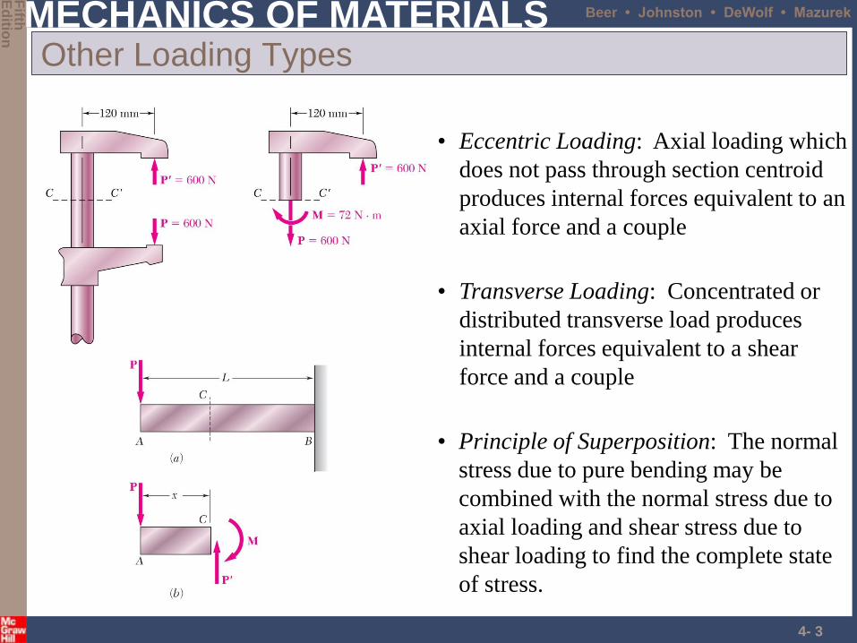
• Principle of Superposition: The normal
stress due to pure bending may be
combined with the normal stress due to
axial loading and shear stress due to
shear loading to find the complete state
of stress.
• Eccentric Loading: Axial loading which
does not pass through section centroid
produces internal forces equivalent to an
axial force and a couple
• Transverse Loading: Concentrated or
distributed transverse load produces
internal forces equivalent to a shear
force and a couple
MECHANICS OF MATERIALS
Fifth
E
ditio
n
Beer • Johnston • DeWolf • Mazurek
4- 4
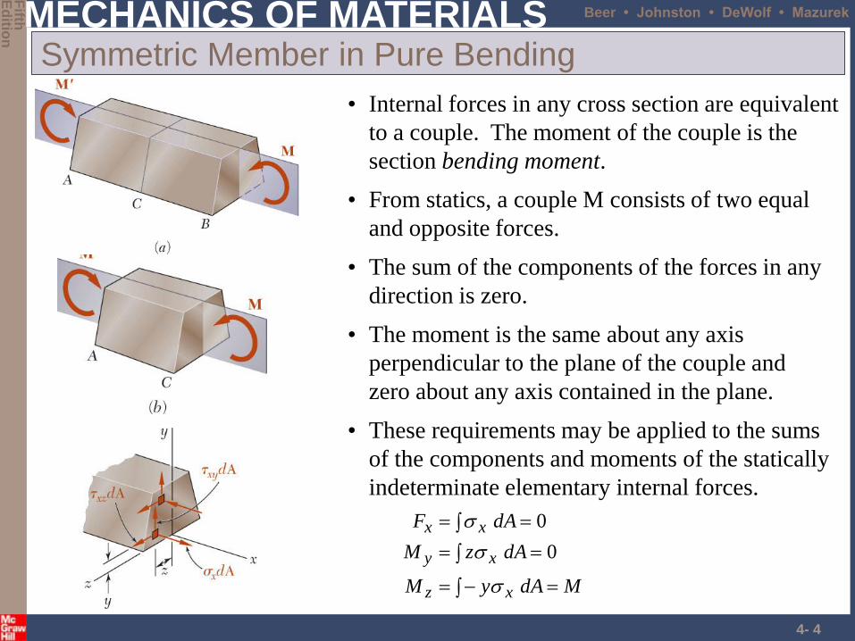
Symmetric Member in Pure Bending
• From statics, a couple M consists of two equal
and opposite forces.
• The sum of the components of the forces in any
direction is zero.
• The moment is the same about any axis
perpendicular to the plane of the couple and
zero about any axis contained in the plane.
• Internal forces in any cross section are equivalent
to a couple. The moment of the couple is the
section bending moment.
MdAyM
dAzM
dAF
xz
xy
xx
0
0
• These requirements may be applied to the sums
of the components and moments of the statically
indeterminate elementary internal forces.
MECHANICS OF MATERIALS
Fifth
E
ditio
n
Beer • Johnston • DeWolf • Mazurek
4- 5
Bending Deformations
• bends uniformly to form a circular arc
• cross-sectional plane passes through arc center
and remains planar
• length of top decreases and length of bottom
increases
• a neutral surface must exist that is parallel to the
upper and lower surfaces and for which the length
does not change
• stresses and strains are negative (compressive)
above the neutral plane and positive (tension)
below it
Beam with a plane of symmetry in pure
bending:
• member remains symmetric
MECHANICS OF MATERIALS
Fifth
E
ditio
n
Beer • Johnston • DeWolf • Mazurek
4- 6
Strain Due to Bending
Consider a beam segment of length L.
After deformation, the length of the neutral
surface remains L. At other sections,
mx
mm
x
c
y
cρ
c
yy
L
yyLL
yL
or
linearly) ries(strain va
MECHANICS OF MATERIALS
Fifth
E
ditio
n
Beer • Johnston • DeWolf • Mazurek
4- 7
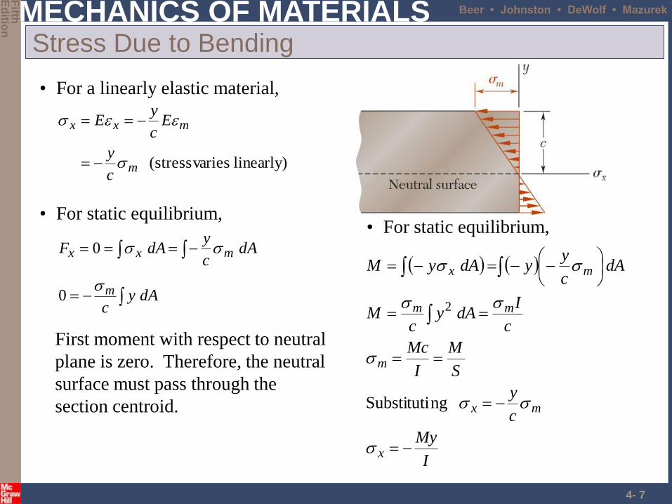
Stress Due to Bending
• For a linearly elastic material,
• For static equilibrium,
dAyc
dAc
ydAF
m
mxx
0
0
First moment with respect to neutral
plane is zero. Therefore, the neutral
surface must pass through the
section centroid.
• For static equilibrium,
I
My
c
y
S
M
I
Mc
c
IdAy
cM
dAc
yydAyM
x
mx
m
mm
mx
ngSubstituti
2
linearly) varies(stressm
mxx
c
y
Ec
yE
MECHANICS OF MATERIALS
Fifth
E
ditio
n
Beer • Johnston • DeWolf • Mazurek
4- 8
Beam Section Properties
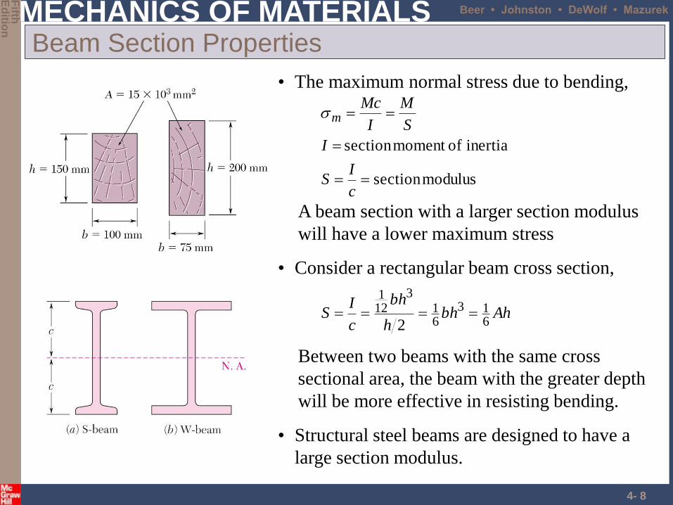
• The maximum normal stress due to bending,
modulussection
inertia ofmoment section
c
IS
I
S
M
I
Mcm
A beam section with a larger section modulus
will have a lower maximum stress
• Consider a rectangular beam cross section,
Ahbhh
bh
c
IS
613
61
3
121
2
Between two beams with the same cross
sectional area, the beam with the greater depth
will be more effective in resisting bending.
• Structural steel beams are designed to have a
large section modulus.
MECHANICS OF MATERIALS
Fifth
E
ditio
n
Beer • Johnston • DeWolf • Mazurek
4- 9
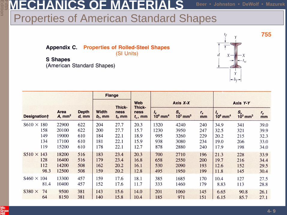
Properties of American Standard Shapes
MECHANICS OF MATERIALS
Fifth
E
ditio
n
Beer • Johnston • DeWolf • Mazurek
4- 10
Deformations in a Transverse Cross Section
• Deformation due to bending moment M is
quantified by the curvature of the neutral surface
EI
M
I
Mc
EcEcc
mm
11
MECHANICS OF MATERIALS
Fifth
E
ditio
n
Beer • Johnston • DeWolf • Mazurek
4- 11
Example 4.01
MECHANICS OF MATERIALS
Fifth
E
ditio
n
Beer • Johnston • DeWolf • Mazurek
4- 12
Example 4.02
MECHANICS OF MATERIALS
Fifth
E
ditio
n
Beer • Johnston • DeWolf • Mazurek
4- 13
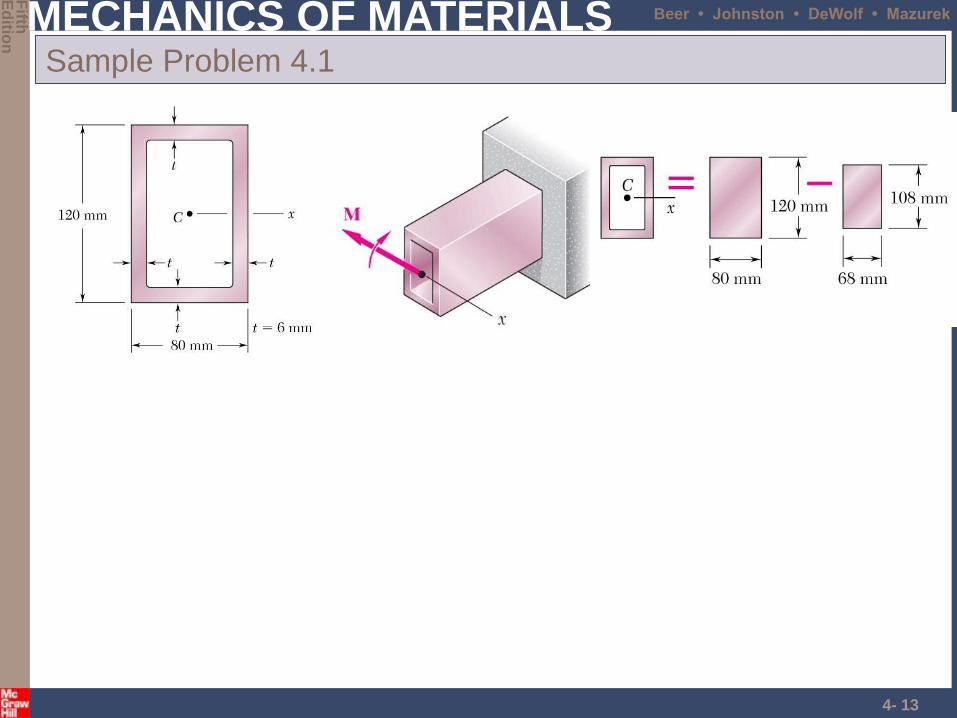
Sample Problem 4.1
MECHANICS OF MATERIALS
Fifth
E
ditio
n
Beer • Johnston • DeWolf • Mazurek
4- 14
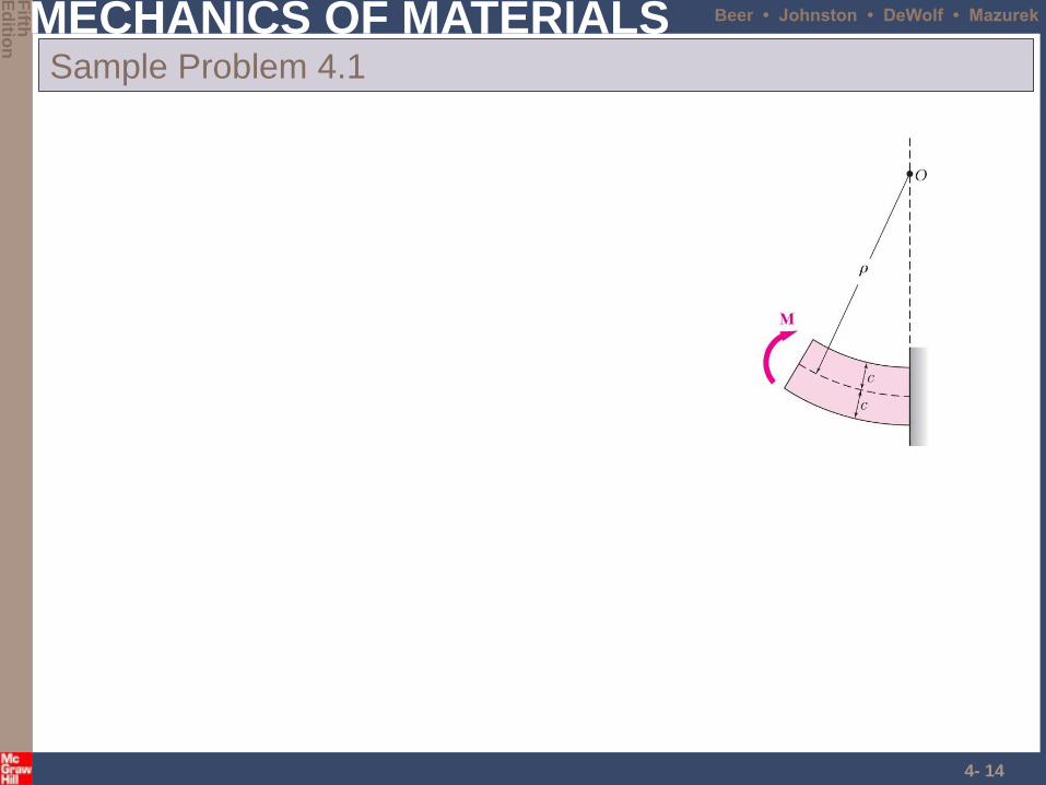
Sample Problem 4.1
MECHANICS OF MATERIALS
Fifth
E
ditio
n
Beer • Johnston • DeWolf • Mazurek
4- 15
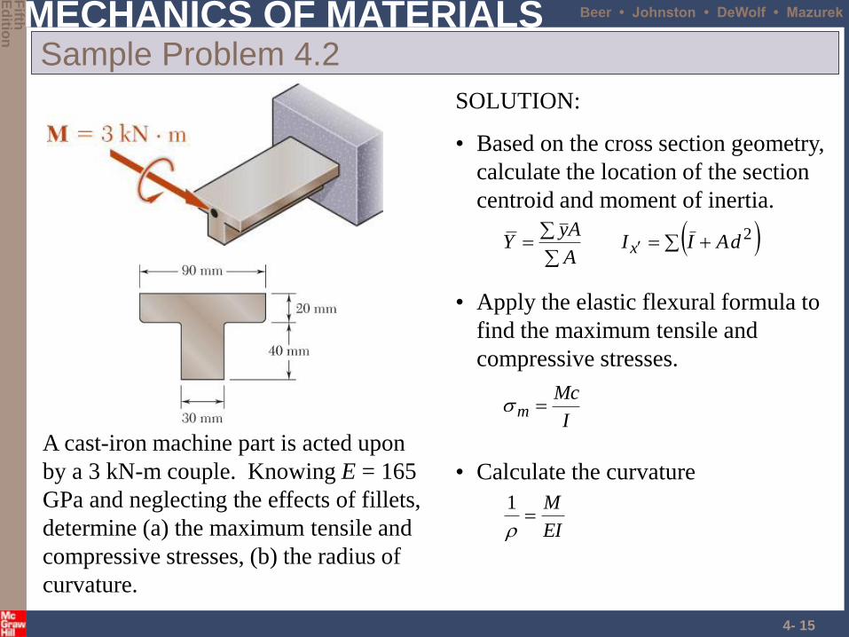
Sample Problem 4.2
SOLUTION:
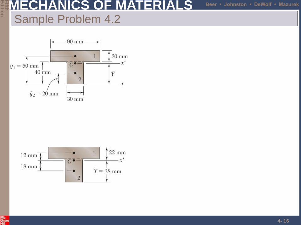
• Based on the cross section geometry,
calculate the location of the section
centroid and moment of inertia.
2dAIIA
AyY x
• Apply the elastic flexural formula to
find the maximum tensile and
compressive stresses.
I
Mcm
• Calculate the curvature
EI
M
1
A cast-iron machine part is acted upon
by a 3 kN-m couple. Knowing E = 165
GPa and neglecting the effects of fillets,
determine (a) the maximum tensile and
compressive stresses, (b) the radius of
curvature.
MECHANICS OF MATERIALS
Fifth
E
ditio
n
Beer • Johnston • DeWolf • Mazurek
4- 16
Sample Problem 4.2
MECHANICS OF MATERIALS
Fifth
E
ditio
n
Beer • Johnston • DeWolf • Mazurek
4- 17
Sample Problem 4.2
MECHANICS OF MATERIALS
Fifth
E
ditio
n
Beer • Johnston • DeWolf • Mazurek
4- 18
Problems
• Page 226
– 4-18, 4-19
MECHANICS OF MATERIALS
Fifth
E
ditio
n
Beer • Johnston • DeWolf • Mazurek
4- 19
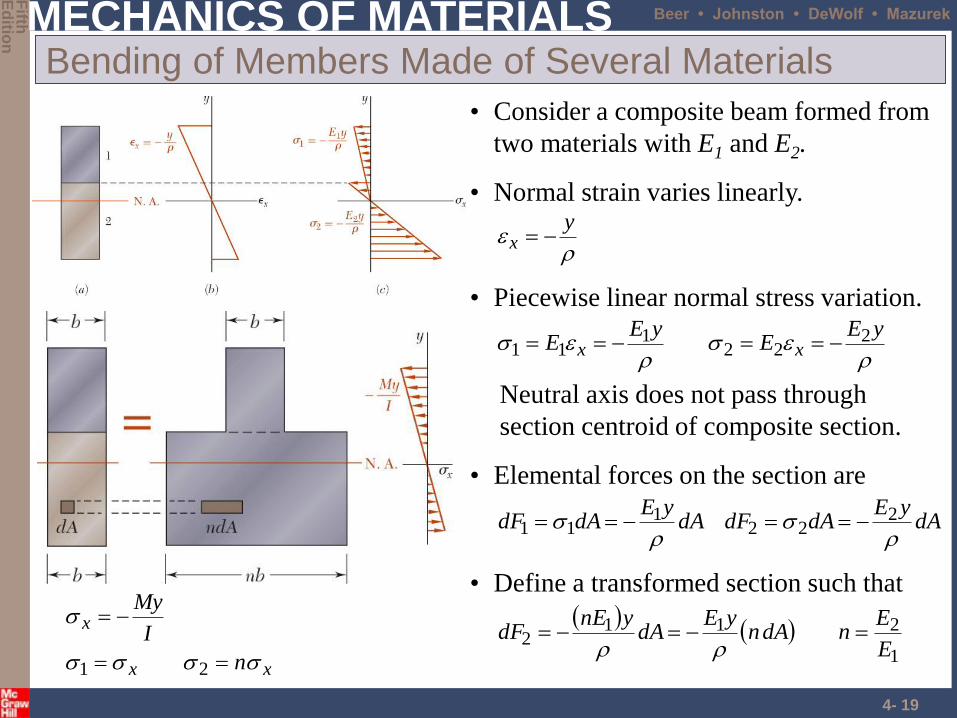
Bending of Members Made of Several Materials
• Normal strain varies linearly.
yx
• Piecewise linear normal stress variation.
yEE
yEE xx
222
111
Neutral axis does not pass through
section centroid of composite section.
• Elemental forces on the section are
dAyE
dAdFdAyE
dAdF
222
111
• Consider a composite beam formed from
two materials with E1 and E2.
xx
x
n
I
My
21
1
2112
E
EndAn
yEdA
ynEdF
• Define a transformed section such that
MECHANICS OF MATERIALS
Fifth
E
ditio
n
Beer • Johnston • DeWolf • Mazurek
4- 20
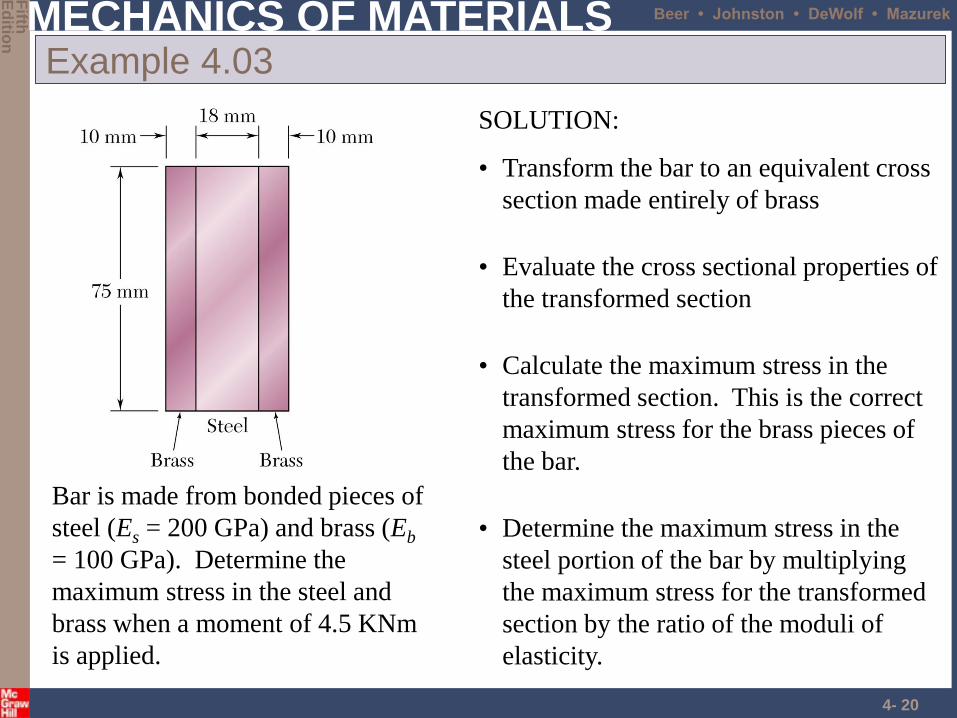
Example 4.03
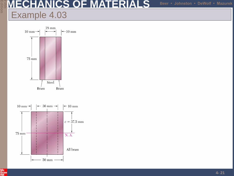
SOLUTION:
• Transform the bar to an equivalent cross
section made entirely of brass
• Evaluate the cross sectional properties of
the transformed section
• Calculate the maximum stress in the
transformed section. This is the correct
maximum stress for the brass pieces of
the bar.
• Determine the maximum stress in the
steel portion of the bar by multiplying
the maximum stress for the transformed
section by the ratio of the moduli of
elasticity.
Bar is made from bonded pieces of
steel (Es = 200 GPa) and brass (Eb
= 100 GPa). Determine the
maximum stress in the steel and
brass when a moment of 4.5 KNm
is applied.
MECHANICS OF MATERIALS
Fifth
E
ditio
n
Beer • Johnston • DeWolf • Mazurek
4- 21
Example 4.03
MECHANICS OF MATERIALS
Fifth
E
ditio
n
Beer • Johnston • DeWolf • Mazurek
4- 22
Sample Problem 4.3
MECHANICS OF MATERIALS
Fifth
E
ditio
n
Beer • Johnston • DeWolf • Mazurek
4- 23
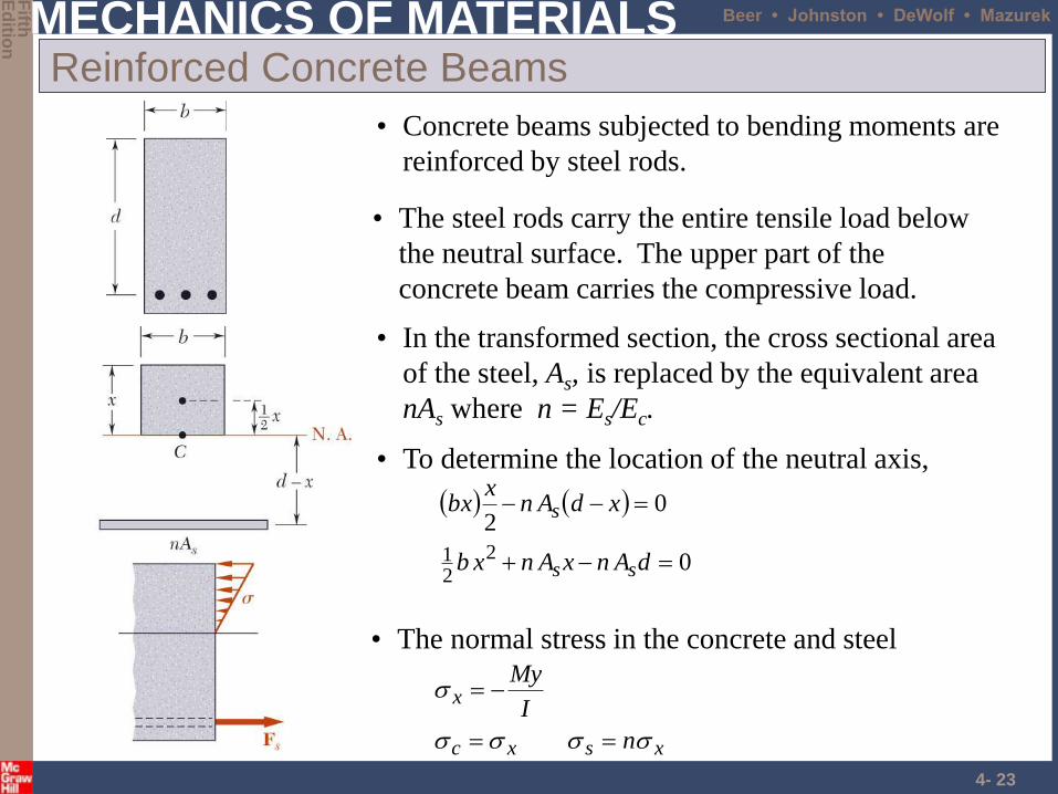
Reinforced Concrete Beams
• Concrete beams subjected to bending moments are
reinforced by steel rods.
• To determine the location of the neutral axis,
0
022
21
dAnxAnxb
xdAnx
bx
ss
s
• The steel rods carry the entire tensile load below
the neutral surface. The upper part of the
concrete beam carries the compressive load.
• In the transformed section, the cross sectional area
of the steel, As, is replaced by the equivalent area
nAs where n = Es/Ec.
• The normal stress in the concrete and steel
xsxc
x
n
I
My
MECHANICS OF MATERIALS
Fifth
E
ditio
n
Beer • Johnston • DeWolf • Mazurek
4- 24
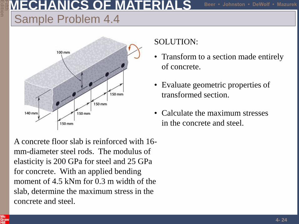
Sample Problem 4.4
SOLUTION:
• Transform to a section made entirely
of concrete.
• Evaluate geometric properties of
transformed section.
• Calculate the maximum stresses
in the concrete and steel.
A concrete floor slab is reinforced with 16-
mm-diameter steel rods. The modulus of
elasticity is 200 GPa for steel and 25 GPa
for concrete. With an applied bending
moment of 4.5 kNm for 0.3 m width of the
slab, determine the maximum stress in the
concrete and steel.
MECHANICS OF MATERIALS
Fifth
E
ditio
n
Beer • Johnston • DeWolf • Mazurek
4- 25
Sample Problem 4.4
MECHANICS OF MATERIALS
Fifth
E
ditio
n
Beer • Johnston • DeWolf • Mazurek
4- 26
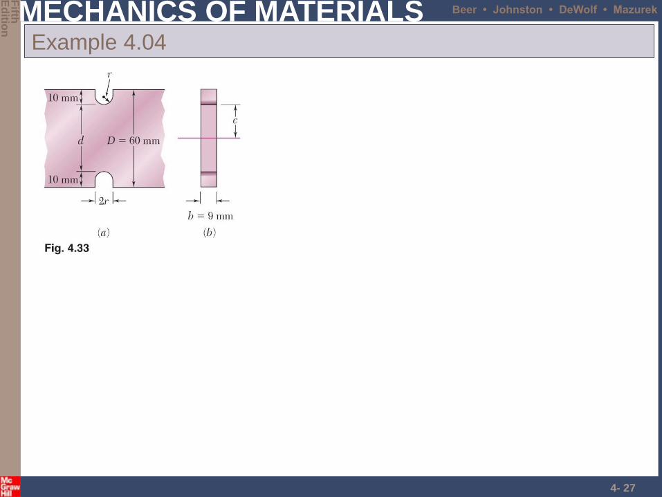
Stress Concentrations
Stress concentrations may occur:
• in the vicinity of points where the
loads are applied
I
McKm
• in the vicinity of abrupt changes
in cross section
MECHANICS OF MATERIALS
Fifth
E
ditio
n
Beer • Johnston • DeWolf • Mazurek
4- 27
Example 4.04
MECHANICS OF MATERIALS
Fifth
E
ditio
n
Beer • Johnston • DeWolf • Mazurek
4- 28
Problems
• Page 240
– 4-50, 4-51, 4-63,4-64
MECHANICS OF MATERIALS
Fifth
E
ditio
n
Beer • Johnston • DeWolf • Mazurek
4- 29
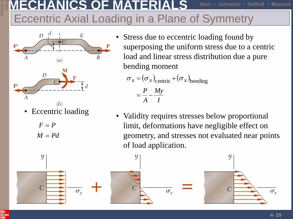
Eccentric Axial Loading in a Plane of Symmetry
• Validity requires stresses below proportional
limit, deformations have negligible effect on
geometry, and stresses not evaluated near points
of load application.
• Eccentric loading
PdM
PF
• Stress due to eccentric loading found by
superposing the uniform stress due to a centric
load and linear stress distribution due a pure
bending moment
I
My
A
P
xxx
bendingcentric
MECHANICS OF MATERIALS
Fifth
E
ditio
n
Beer • Johnston • DeWolf • Mazurek
4- 30
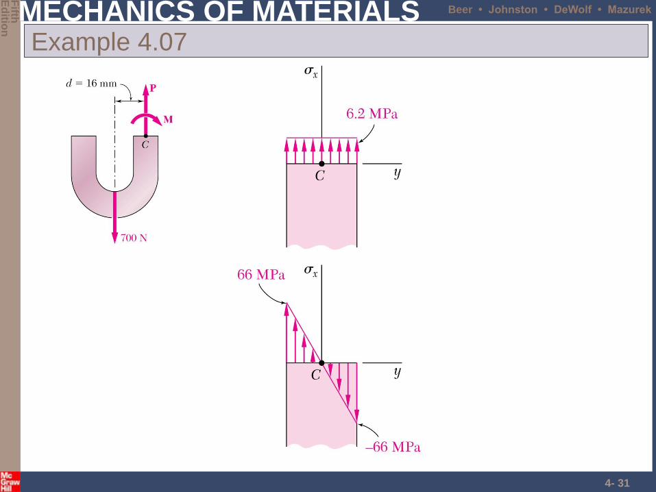
Example 4.07
An open-link chain is obtained by
bending low-carbon steel rods into the
shape shown. For 700 N load, determine
(a) maximum tensile and compressive
stresses, (b) distance between section
centroid and neutral axis
SOLUTION:
• Find the equivalent centric load and
bending moment
• Superpose the uniform stress due to
the centric load and the linear stress
due to the bending moment.
• Evaluate the maximum tensile and
compressive stresses at the inner
and outer edges, respectively, of the
superposed stress distribution.
• Find the neutral axis by determining
the location where the normal stress
is zero.
MECHANICS OF MATERIALS
Fifth
E
ditio
n
Beer • Johnston • DeWolf • Mazurek
4- 31
Example 4.07
MECHANICS OF MATERIALS
Fifth
E
ditio
n
Beer • Johnston • DeWolf • Mazurek
4- 32
Example 4.07
• Maximum tensile and compressive
stresses
662.6
662.6
0
0
mc
mt
MPa2.72t
MPa8.59c
• Neutral axis location
Nm.211
m109.1017Pa102.6
0
4126
0
0
M
I
A
Py
I
My
A
P
mm56.00 y
MECHANICS OF MATERIALS
Fifth
E
ditio
n
Beer • Johnston • DeWolf • Mazurek
4- 33
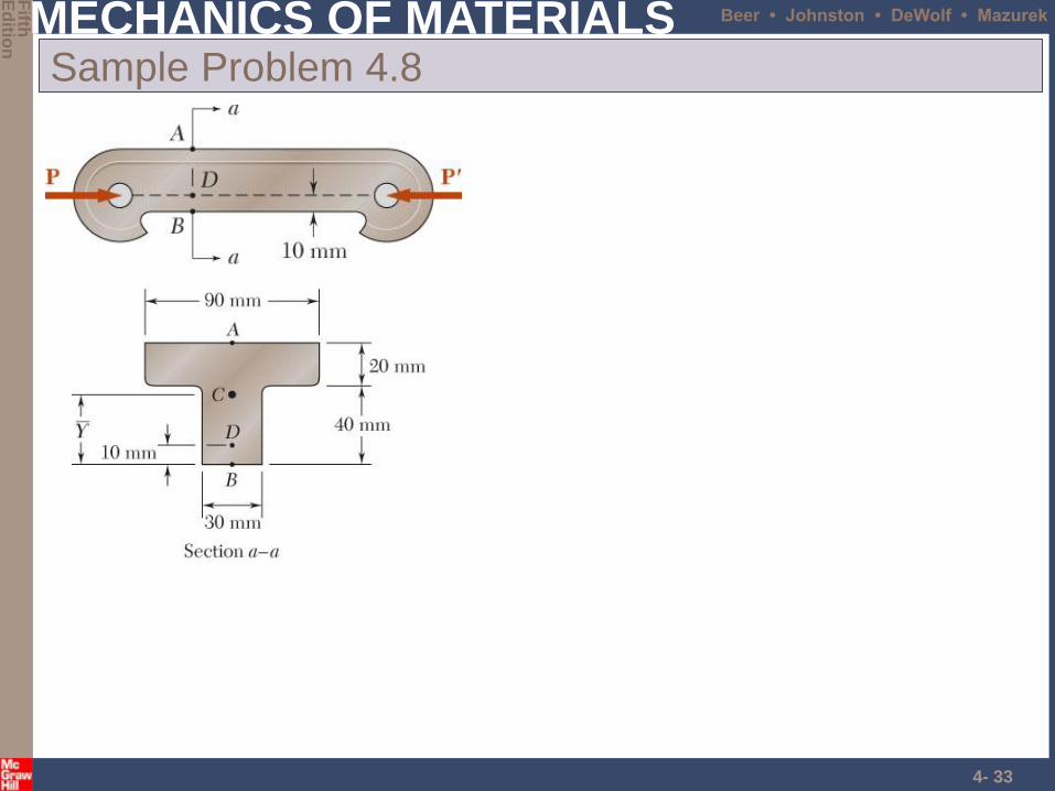
Sample Problem 4.8
MECHANICS OF MATERIALS
Fifth
E
ditio
n
Beer • Johnston • DeWolf • Mazurek
4- 34
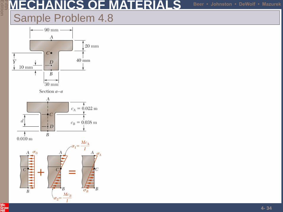
Sample Problem 4.8
MECHANICS OF MATERIALS
Fifth
E
ditio
n
Beer • Johnston • DeWolf • Mazurek
4- 35
Problems
• Page 256
– 4-75, 4-76
• Page 264,265
– 4-102, 4-103