11
GATE VALVE SERIES GATE VALVE SERIES 01-31P

FIGURE NUMBER SYSTEM
Steel Gate Valve Figure Number System
1 Use "W" to express seat sealing surface material which is processed directly by valve body.
2 When the materials of sealing surface are different, use low hardness material symbol to express.
3 Special requirements not shown ,should be indicated in the purchase order
The models listed in the sample book have no reference to pressure sizes and valve material symbols, they are to be
decided by users.
Gate valve 10 ANSI CLASS150 Raised Face Ends Flexible wedge Body&Bonnet&Wedge Cast Steel WCB Seat sealing
face material 13Cr Cone Gear operated
80-Z2RF08W
10 -5Z1RF0CH
Gate valve DN80 PN25 Raised Face Ends Flexible wedge Body&Bonnet& Wedge Stainless Steel CF8 Seat sealing face Body
machined Handwheel operated
For example:
Note:
1
2
3
4
5
6
7
8
Size
Operation type
Valve Type
Pressure
Connection Ends
Structure Type
Basic Material
Material of Seat
face or Liner
xxin xx mm
1-Bare Stem2-Chain-Wheel
Operated
4-Spur Gear
Operated
5-Cone Gear
Opearted
9-Electric
Operated
Manual Operated
(omit)
Z- Gate Valve
0-PN1.0 1-PN1.6 CLASS150 2-PN2.5 3-CLASS300 4-PN4.0 CLASS400 6-PN6.4 CLASS600
9-CLASS900 10-PN10.0 15-CLASS1500 16-PN16.0 20-PN20.0 25-CLASS2500
RF-Raised Face FF-Flat FaceMFM-Male and
Female Face
TG-Tongue and
Groove FaceRJ-Ring Joint BW-Buttweld
0-Flexible
Wedge1-Solid Wedge
2-Solid Double
Wedge
3-Parellel Single Disc
3T-Adjust Type
3L-Adiversion Hole Type
4-Parellel Double
Disc
C-WCB C5-C5 C6-WC6 C9-WC9 BL-LCB CL-LCC
8-CF8 8M-CF8M 3-CF3 3M-CF3M
H-Cr13 Cr13 S.S E-18-8 18-8 S.S R-Mo2Ti Mo2Ti S.S
D- Nitriding Steel M- Monel Alloy Y- Stellited
ML-MONEL
1 2 3 4 5 6 7 8
GATE VALVE SERIESGATE VALVE SERIES01-31P
01
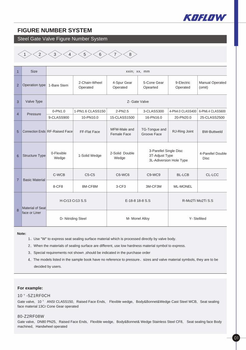
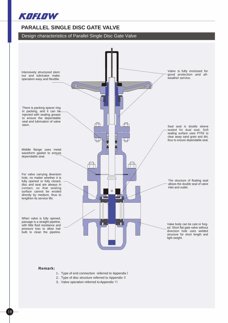
Design characteristics of Parallel Single Disc Gate Valve
Valve is fully enclosed forgood protection and all-weather service. .
Seal seat is double sleeve sealed for dual seal. Soft sealing surface uses PTFE to clear away sand grain and dirt, thus to ensure dependable seal.
The structure of floating seat allows the double seal of valve inlet and outlet. .
Valve body can be cast or forg-ed. Short flat gate valve without diversion hole uses welded structure for short length and light weight. .
Intensively structured stem nut and lubricator make operation easy and flexible.
Middle flange uses metal waveform gasket to ensure dependable seal. .
For valve carrying diversion hole, no matter whether it is fully opened or fully closed, disc and seat are always in contact, so that sealing surface cannot be eroded directly by medium, thus to lengthen its service life. .
When valve is fully opened, passage is a straight pipeline, with little fluid resistance and pressure loss to allow hair bulb to clean the pipeline.
There is packing spacer ring in packing, and it can be injected with sealing grease to ensure the dependable seal and lubrication of valve stem. .
PARALLEL SINGLE DISC GATE VALVE
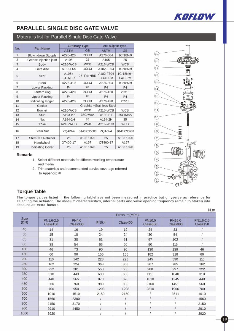
Materails list for Parallel Single Disc Gate Valve
No. Part Name
1
2
3
4
5
6
7
8
9
10
11
12
13
14
15
16
17
18
19
Blown down Stopple
Grease injection joint
Body
Gate disc
Seat
Stem
Lower Packing
Lantern ring
Upper Packing
Indicating Finger
Gasket
Bonnet
Stud
Nut
Yoke
Stem Nut
Stem Nut Retainer
Handwheel
Indicating Cover
Graphite +Stainless Steel
GB
2Cr13
25
WCB
1Cr13
25+F4+NBR
1Cr13
F4
2Cr13
F4
2Cr13
WCB
35CrMoA
35
WCB
ZQAl9-4
25
QT400-17
25
ASTM
A276-420
A105
A216-WCB
A182-F6a
A105+
F4+NBR
A276-410
F4
A276-420
F4
A276-420
A216-WCB
A193-B7
A194-2H
A216-WCB
B148 C95600
A108 1020
A197
A108 1020
GB
1Cr18Ni9
25
WCB
1Cr18Ni9
1Cr18Ni9+
F4+FPM
1Cr18Ni9
F4
2Cr13
F4
2Cr13
WCB
35CrMoA
35
WCB
B148 C95600
A108 1020
A197
A108 1020
19
18
17
16
15
14
13
12
11
10
9
8
7
6
5
4
3
2
1
Remark:
PARALLEL SINGLE DISC GATE VALVE
The torque values listed in the following table have not been measured in practice but only serve as reference for selecting the actuator. The medium characteristics, internal parts and valve opening frequency remain to be taken into account as extra factors.
N.m
Size(DN)
Pressure(MPa)
40
50
65
80
100
150
200
250
300
350
400
450
500
600
700
800
900
1000
14
15
31
38
46
60
110
162
222
310
440
560
700
1010
1560
2150
2910
3920
16
18
38
54
73
90
142
224
281
443
565
760
950
1510
2300
3170
4450
19
24
51
66
90
156
228
368
550
630
870
980
1208
2150
/
/
/
/
19
24
51
66
90
156
228
368
550
630
870
980
1208
2150
/
/
/
/
24
30
67
90
130
182
245
367
980
1118
1618
2160
2810
/
/
/
/
/
33
54
102
115
139
318
590
785
997
1040
1245
1451
1966
3611
/
/
/
/
/
/
/
/
46
60
110
162
222
310
440
560
700
1010
1560
2150
2910
3920
Torque Table
PN1.6-2.5Class150
PN4.0Class300
PN6.4 Class400PN10.0
Class600PN16.0
Class900PN1.6-2.5Class150
1 Select different materials for different working temperature
and media
2 Trim materials and recommended service coverage referred
to Appendix
ZQAl9-4
25
QT400-17
25
ASTM
A276-304
A105
A216-WCB
A182-F304
A182-F304
+F4+FPM
A276-304
F4
A276-420
F4
A276-420
A216-WCB
A193-B7
A194-2H
A216-WCB
1 Type of end connection referred to Appendix
2 Type of disc structure referred to Appendix
3 Valve operation referred to Appendix
Remark:
18 19
Ordinary Type Anti-sulphur Type
Design characteristics of Parallel Single Disc Gate Valve
Valve is fully enclosed forgood protection and all-weather service. .
Seal seat is double sleeve sealed for dual seal. Soft sealing surface uses PTFE to clear away sand grain and dirt, thus to ensure dependable seal.
The structure of floating seat allows the double seal of valve inlet and outlet. .
Valve body can be cast or forg-ed. Short flat gate valve without diversion hole uses welded structure for short length and light weight. .
Intensively structured stem nut and lubricator make operation easy and flexible.
Middle flange uses metal waveform gasket to ensure dependable seal. .
For valve carrying diversion hole, no matter whether it is fully opened or fully closed, disc and seat are always in contact, so that sealing surface cannot be eroded directly by medium, thus to lengthen its service life. .
When valve is fully opened, passage is a straight pipeline, with little fluid resistance and pressure loss to allow hair bulb to clean the pipeline.
There is packing spacer ring in packing, and it can be injected with sealing grease to ensure the dependable seal and lubrication of valve stem. .
PARALLEL SINGLE DISC GATE VALVE
Materails list for Parallel Single Disc Gate Valve
No. Part Name
1
2
3
4
5
6
7
8
9
10
11
12
13
14
15
16
17
18
19
Blown down Stopple
Grease injection joint
Body
Gate disc
Seat
Stem
Lower Packing
Lantern ring
Upper Packing
Indicating Finger
Gasket
Bonnet
Stud
Nut
Yoke
Stem Nut
Stem Nut Retainer
Handwheel
Indicating Cover
Graphite +Stainless Steel
GB
2Cr13
25
WCB
1Cr13
25+F4+NBR
1Cr13
F4
2Cr13
F4
2Cr13
WCB
35CrMoA
35
WCB
ZQAl9-4
25
QT400-17
25
ASTM
A276-420
A105
A216-WCB
A182-F6a
A105+
F4+NBR
A276-410
F4
A276-420
F4
A276-420
A216-WCB
A193-B7
A194-2H
A216-WCB
B148 C95600
A108 1020
A197
A108 1020
GB
1Cr18Ni9
25
WCB
1Cr18Ni9
1Cr18Ni9+
F4+FPM
1Cr18Ni9
F4
2Cr13
F4
2Cr13
WCB
35CrMoA
35
WCB
B148 C95600
A108 1020
A197
A108 1020
19
18
17
16
15
14
13
12
11
10
9
8
7
6
5
4
3
2
1
Remark:
PARALLEL SINGLE DISC GATE VALVE
The torque values listed in the following table have not been measured in practice but only serve as reference for selecting the actuator. The medium characteristics, internal parts and valve opening frequency remain to be taken into account as extra factors.
N.m
Size(DN)
Pressure(MPa)
40
50
65
80
100
150
200
250
300
350
400
450
500
600
700
800
900
1000
14
15
31
38
46
60
110
162
222
310
440
560
700
1010
1560
2150
2910
3920
16
18
38
54
73
90
142
224
281
443
565
760
950
1510
2300
3170
4450
19
24
51
66
90
156
228
368
550
630
870
980
1208
2150
/
/
/
/
19
24
51
66
90
156
228
368
550
630
870
980
1208
2150
/
/
/
/
24
30
67
90
130
182
245
367
980
1118
1618
2160
2810
/
/
/
/
/
33
54
102
115
139
318
590
785
997
1040
1245
1451
1966
3611
/
/
/
/
/
/
/
/
46
60
110
162
222
310
440
560
700
1010
1560
2150
2910
3920
Torque Table
PN1.6-2.5Class150
PN4.0Class300
PN6.4 Class400PN10.0
Class600PN16.0
Class900PN1.6-2.5Class150
1 Select different materials for different working temperature
and media
2 Trim materials and recommended service coverage referred
to Appendix
ZQAl9-4
25
QT400-17
25
ASTM
A276-304
A105
A216-WCB
A182-F304
A182-F304
+F4+FPM
A276-304
F4
A276-420
F4
A276-420
A216-WCB
A193-B7
A194-2H
A216-WCB
1 Type of end connection referred to Appendix
2 Type of disc structure referred to Appendix
3 Valve operation referred to Appendix
Remark:
18 19
Ordinary Type Anti-sulphur Type
PARALLEL SINGLE DISC GATE VALVE PARALLEL SINGLE DISC GATE VALVE
Parallel Single Disc Gate Valve Product Line
DN
NPS
25
1
3211- /4
4011- /2
50
2
6512- /2
80
3
100
4
125
5
150
6
200
8
250
10
300
12
350
14
400
16
450
18
500
20
600
24
650
26
700
28
750
30
800
32
900
36
1000
40
Hand operated
Gear operated
Electricoperated
* * *
*
*
*
*
*
*
*
*
*
*
*
*
*
*
*
*
*
*
*
*
*
*
*
*
*
*
*
*
*
*
*
*
*
*
*
*
*
*
*
*
*
*
*
*
*
*
*
*
*
*
*
*
*
*
*
*
*
*
*
*
*
*
*
*
*
*
*
*
*
*
*
*
*
*
*
*
*
*
*
*
*
*
*
*
*
*
*
*
*
*
PN
1.6
2.5
4.0
6.4
10.0
16.0
*
*
*
*
*
*
*
*
*
*
*
*
*
*
*
*
*
*
*
*
*
*
*
*
*
*
*
*
*
*
*
*
*
*
*
*
*
*
*
*
*
*
*
*
*
*
*
*
*
*
*
*
*
*
*
*
*
*
*
*
*
*
*
*
*
*
*
*
*
*
*
*
*
*
*
*
*
CL
AS
S
150
300
400
600
900
*
*
*
*
*
*
*
*
*
*
*
*
*
*
*
*
*
*
*
*
*
*
*
*
*
*
*
*
*
*
*
*
*
*
*
*
*
*
*
*
*
*
*
*
*
*
*
*
*
*PN
1.6
2.5
4.0
6.4
10.0
16.0
*
*
*
*
*
*
*
*
*
*
*
*
*
*
*
*
*
*
*
*
*
*
*
*
*
*
*
*
*
*
*
*
*
*
*
*
*
*
*
*
*
*
CL
AS
S
150
300
400
600
900
* * * * * * * * * * * * * *
*
*
*
*
*
*
*
*
*
*
*
*
*
*
*
*
*
*
*
*
*
*
*
*
*
*
*
*
*
*
*
*
*
*
*
*
*
*
*
*
*
*
*
*
*
*
*
*
*
*
*
*
*
*
*
*
*
*
*
*
*
*
*
*
*
*
*
*
*
*
*
*
*
*
*
*
*
*
*
*
*
*
*
*
*
*
*
*
*
*
*
*
*
*
*
PN
1.6
2.5
4.0
6.4
10.0
16.0
* * * * * * * * * * * * * *
*
*
*
*
*
*
*
*
*
*
*
*
*
*
*
*
*
*
*
*
*
*
*
*
*
*
*
*
*
*
*
*
*
*
*
*
*
*
*
*
*
*
*
*
*
*
*
*
*
*
*
*
*
*
*
*
*
*
*
*
*
*
*
*
*
*
*
*
*
*
*
*
*
*
*
CL
AS
S
150
300
400
600
900
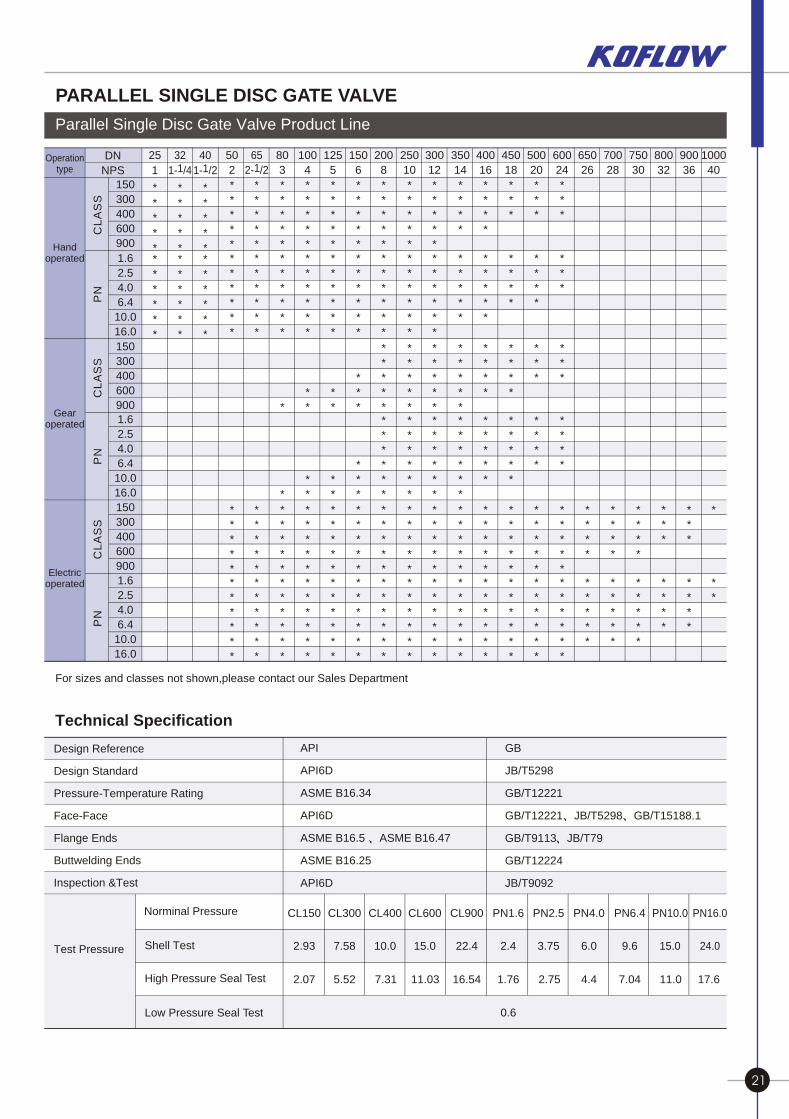
For sizes and classes not shown,please contact our Sales Department
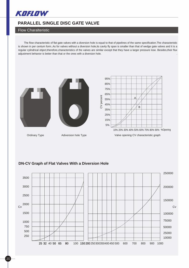
Flow Charalteristic
The flow characteristic of flat gate valves with a diversion hole is equal to that of pipelines of the same specification.The characteristic
is shown in per centum form..As for valves without a diversion hole,its cavity fly span is smaller than that of wedge gate valves and it is a
regular cylindrical object,therefore,characteristics of the valves are similar except that they have a larger pressure lose. Besides,their flux
adjustment behavior is better than that or the ones with a diversion hole. .
A
B
95%
85%
75%
65%
55%
45%
35%
25%
15%
5%
CV
pe
rce
nt
Ordinary Type Adiversion hole Type
DN-CV Graph of Flat Valves With a Diversion Hole
25 32 40 50 80 100 150
250
500
1000
750
1500
2000
2500
3000
3500
65 200 250300350400 450 500 600 700 800 900 1000
250000
200000
150000
100000
75000
50000
25000
10000
Cv Cv
25 32 50 80 15065 200
Valve opening CV characteristic graph
Technical Specification
Design Reference
Design Standard
Pressure-Temperature Rating
Face-Face
Flange Ends
Buttwelding Ends
Inspection &Test
Test Pressure Shell Test
High Pressure Seal Test
Low Pressure Seal Test
GB
JB/T5298
GB/T12221
GB/T12221 JB/T5298 GB/T15188.1
GB/T9113 JB/T79
GB/T12224
JB/T9092
PN1.6
2.4
PN2.5
3.75
PN4.0
6.0
PN6.4
9.6
PN10.0
15.0
PN16.0
24.0
1.76 2.75 4.4 7.04 11.0 17.6
0.6
CL150
2.93
CL300
7.58
CL400
10.0
CL600
15.0
CL900
22.4
2.07 5.52 7.31 11.03 16.54
API
API6D
ASME B16.34
API6D
ASME B16.5 ASME B16.47
ASME B16.25
API6D
Norminal Pressure
Operation type
10% 20% 30% 40% 50% 60% 70% 80% 90% %Opening
20 21
PARALLEL SINGLE DISC GATE VALVE PARALLEL SINGLE DISC GATE VALVE
Parallel Single Disc Gate Valve Product Line
DN
NPS
25
1
3211- /4
4011- /2
50
2
6512- /2
80
3
100
4
125
5
150
6
200
8
250
10
300
12
350
14
400
16
450
18
500
20
600
24
650
26
700
28
750
30
800
32
900
36
1000
40
Hand operated
Gear operated
Electricoperated
* * *
*
*
*
*
*
*
*
*
*
*
*
*
*
*
*
*
*
*
*
*
*
*
*
*
*
*
*
*
*
*
*
*
*
*
*
*
*
*
*
*
*
*
*
*
*
*
*
*
*
*
*
*
*
*
*
*
*
*
*
*
*
*
*
*
*
*
*
*
*
*
*
*
*
*
*
*
*
*
*
*
*
*
*
*
*
*
*
*
*
*
PN
1.6
2.5
4.0
6.4
10.0
16.0
*
*
*
*
*
*
*
*
*
*
*
*
*
*
*
*
*
*
*
*
*
*
*
*
*
*
*
*
*
*
*
*
*
*
*
*
*
*
*
*
*
*
*
*
*
*
*
*
*
*
*
*
*
*
*
*
*
*
*
*
*
*
*
*
*
*
*
*
*
*
*
*
*
*
*
*
*
CL
AS
S
150
300
400
600
900
*
*
*
*
*
*
*
*
*
*
*
*
*
*
*
*
*
*
*
*
*
*
*
*
*
*
*
*
*
*
*
*
*
*
*
*
*
*
*
*
*
*
*
*
*
*
*
*
*
*PN
1.6
2.5
4.0
6.4
10.0
16.0
*
*
*
*
*
*
*
*
*
*
*
*
*
*
*
*
*
*
*
*
*
*
*
*
*
*
*
*
*
*
*
*
*
*
*
*
*
*
*
*
*
*
CL
AS
S
150
300
400
600
900
* * * * * * * * * * * * * *
*
*
*
*
*
*
*
*
*
*
*
*
*
*
*
*
*
*
*
*
*
*
*
*
*
*
*
*
*
*
*
*
*
*
*
*
*
*
*
*
*
*
*
*
*
*
*
*
*
*
*
*
*
*
*
*
*
*
*
*
*
*
*
*
*
*
*
*
*
*
*
*
*
*
*
*
*
*
*
*
*
*
*
*
*
*
*
*
*
*
*
*
*
*
*
PN
1.6
2.5
4.0
6.4
10.0
16.0
* * * * * * * * * * * * * *
*
*
*
*
*
*
*
*
*
*
*
*
*
*
*
*
*
*
*
*
*
*
*
*
*
*
*
*
*
*
*
*
*
*
*
*
*
*
*
*
*
*
*
*
*
*
*
*
*
*
*
*
*
*
*
*
*
*
*
*
*
*
*
*
*
*
*
*
*
*
*
*
*
*
*
CL
AS
S
150
300
400
600
900
For sizes and classes not shown,please contact our Sales Department
Flow Charalteristic
The flow characteristic of flat gate valves with a diversion hole is equal to that of pipelines of the same specification.The characteristic
is shown in per centum form..As for valves without a diversion hole,its cavity fly span is smaller than that of wedge gate valves and it is a
regular cylindrical object,therefore,characteristics of the valves are similar except that they have a larger pressure lose. Besides,their flux
adjustment behavior is better than that or the ones with a diversion hole. .
A
B
95%
85%
75%
65%
55%
45%
35%
25%
15%
5%
CV
pe
rce
nt
Ordinary Type Adiversion hole Type
DN-CV Graph of Flat Valves With a Diversion Hole
25 32 40 50 80 100 150
250
500
1000
750
1500
2000
2500
3000
3500
65 200 250300350400 450 500 600 700 800 900 1000
250000
200000
150000
100000
75000
50000
25000
10000
Cv Cv
25 32 50 80 15065 200
Valve opening CV characteristic graph
Technical Specification
Design Reference
Design Standard
Pressure-Temperature Rating
Face-Face
Flange Ends
Buttwelding Ends
Inspection &Test
Test Pressure Shell Test
High Pressure Seal Test
Low Pressure Seal Test
GB
JB/T5298
GB/T12221
GB/T12221 JB/T5298 GB/T15188.1
GB/T9113 JB/T79
GB/T12224
JB/T9092
PN1.6
2.4
PN2.5
3.75
PN4.0
6.0
PN6.4
9.6
PN10.0
15.0
PN16.0
24.0
1.76 2.75 4.4 7.04 11.0 17.6
0.6
CL150
2.93
CL300
7.58
CL400
10.0
CL600
15.0
CL900
22.4
2.07 5.52 7.31 11.03 16.54
API
API6D
ASME B16.34
API6D
ASME B16.5 ASME B16.47
ASME B16.25
API6D
Norminal Pressure
Operation type
10% 20% 30% 40% 50% 60% 70% 80% 90% %Opening
20 21
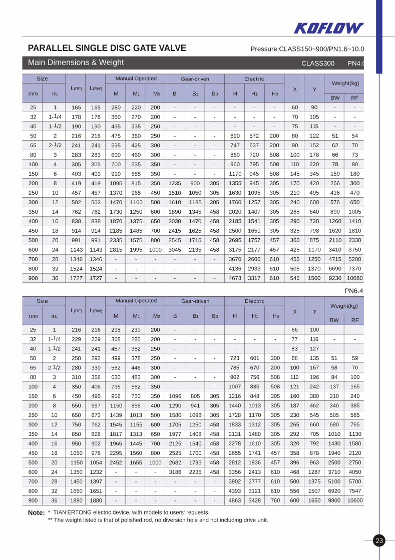
PARALLEL SINGLE DISC GATE VALVE PARALLEL SINGLE DISC GATE VALVE
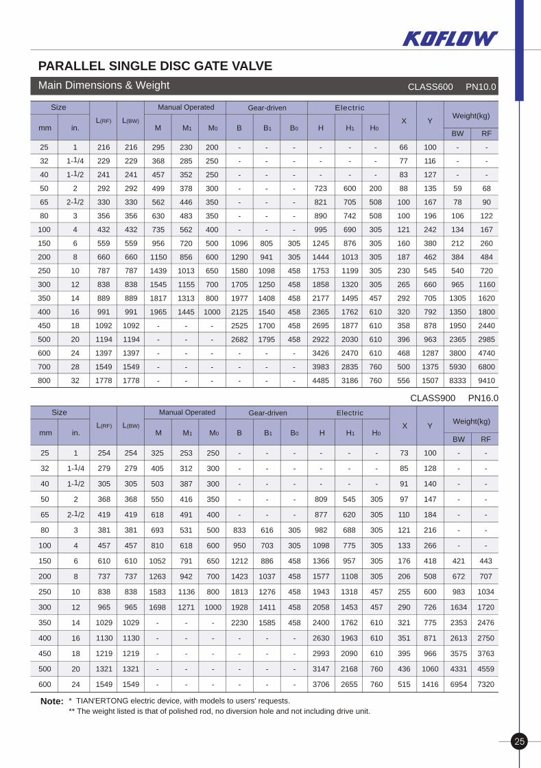
Main Dimensions & Weight CLASS300 PN4.0
PN6.4
* TIAN'ERTONG electric device, with models to users' requests.
** The weight listed is that of polished rod, no diversion hole and not including drive unit. Note:
mm in.L(RF) L(BW) X Y
Weight(kg)
M M1 M0 B B1 B0 H H1 H0
25
32
40
50
65
80
100
150
200
250
300
350
400
450
500
600
700
800
900
1
11- /4
11- /2
2
12- /2
3
4
6
8
10
12
14
16
18
20
24
28
32
36
165
178
190
216
241
283
305
403
419
457
502
762
838
914
991
1143
1346
1524
1727
165
178
190
216
241
283
305
403
419
457
502
762
838
914
991
1143
1346
1524
1727
280
350
435
475
535
600
700
910
1095
1370
1470
1730
1870
2185
2335
2815
-
-
-
220
270
335
360
425
460
535
685
815
965
1100
1250
1375
1485
1575
1995
-
-
-
200
200
250
250
300
300
350
350
350
450
500
600
650
700
800
1000
-
-
-
-
-
-
-
-
-
-
-
1235
1510
1610
1890
2030
2415
2545
3045
-
-
-
-
-
-
-
-
-
-
-
900
1050
1185
1345
1470
1625
1715
2135
-
-
-
-
-
-
-
-
-
-
-
305
305
305
458
458
458
458
458
-
-
-
-
-
-
690
747
860
960
1170
1355
1630
1760
2020
2185
2500
2695
3175
3670
4136
4673
-
-
-
572
637
720
795
945
945
1095
1257
1407
1541
1651
1757
2177
2606
2933
3317
-
-
-
200
200
508
508
508
305
305
305
305
305
305
457
457
610
610
610
60
70
75
80
90
100
110
145
170
210
240
265
290
325
360
425
455
505
545
90
105
115
122
152
178
220
345
420
495
600
640
720
798
875
1170
1250
1370
1500
BW
-
-
-
51
62
66
78
159
266
416
576
890
1260
1620
2110
3410
4715
6690
9230
RF
-
-
-
54
70
73
90
180
300
470
650
1005
1410
1810
2330
3750
5200
7370
10080
Electric Manual Operated Gear-drivenSize
mm in.L(RF) L(BW) X Y
Weight(kg)
M M1 M0 B B1 B0 H H1 H0
25
32
40
50
65
80
100
150
200
250
300
350
400
450
500
600
700
800
900
1
11- /4
11- /2
2
12- /2
3
4
6
8
10
12
14
16
18
20
24
28
32
36
216
229
241
250
280
310
350
450
550
650
750
850
950
1050
1150
1350
1450
1650
1880
216
229
241
292
330
356
406
495
597
673
762
826
902
978
1054
1232
1397
1651
1880
295
368
457
499
562
630
735
956
1150
1439
1545
1817
1965
2295
2452
-
-
-
-
230
285
352
378
446
483
562
720
856
1013
1155
1313
1445
1560
1655
-
-
-
-
200
200
250
250
300
300
350
350
400
500
600
650
700
800
1000
-
-
-
-
-
-
-
-
-
-
-
1096
1290
1580
1705
1977
2125
2525
2682
3186
-
-
-
-
-
-
-
-
-
-
805
941
1098
1250
1408
1540
1700
1795
2235
-
-
-
-
-
-
-
-
-
-
305
305
305
458
458
458
458
458
458
-
-
-
-
-
-
723
785
902
1007
1216
1440
1728
1833
2131
2278
2655
2812
3356
3902
4393
4863
-
-
-
601
670
756
835
848
1013
1170
1312
1480
1610
1741
1936
2413
2777
3121
3428
-
-
-
200
200
508
508
305
305
305
305
305
305
457
457
610
610
610
760
66
77
83
88
100
110
121
160
187
230
265
292
320
358
396
468
500
556
600
100
116
127
135
167
196
242
380
462
545
660
705
792
878
963
1287
1375
1507
1650
BW
-
-
-
51
58
84
137
210
340
505
680
1010
1430
1940
2500
3710
5100
6920
9800
RF
-
-
-
59
70
100
165
240
385
565
765
1130
1580
2120
2750
4050
5700
7547
10600
Electric Manual Operated Gear-drivenSize
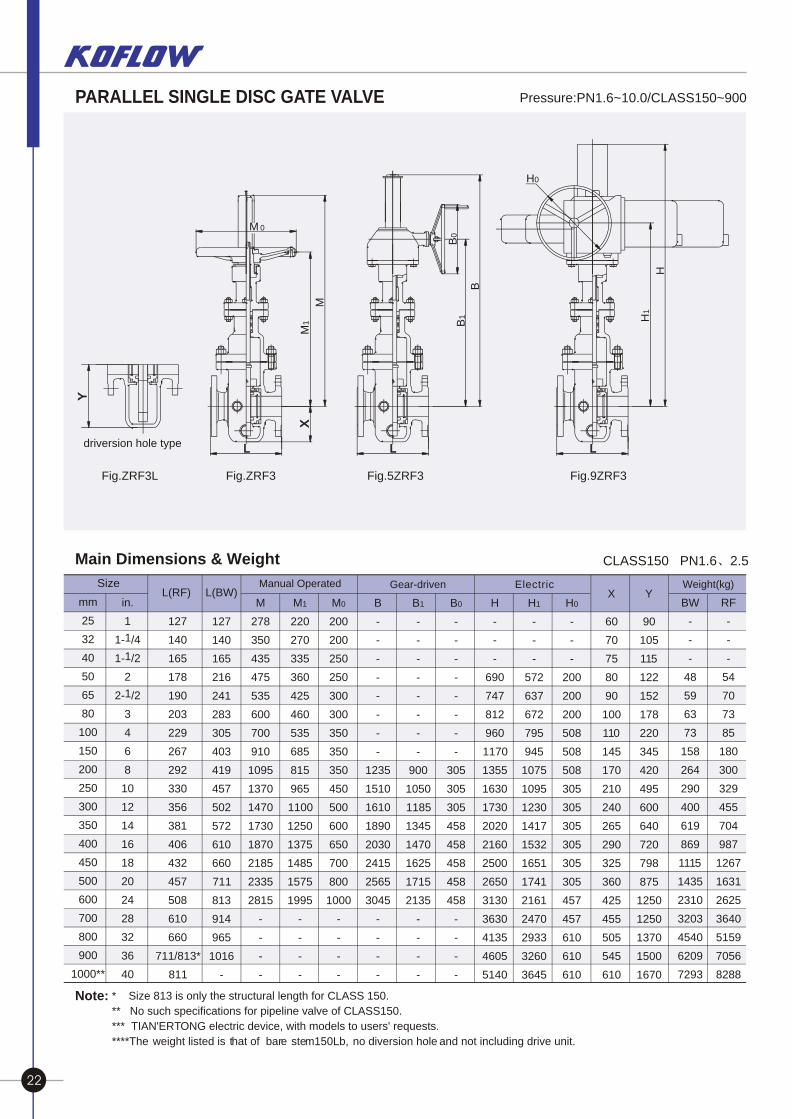
Main Dimensions & Weight CLASS150 PN1.6 2.5
Note: * Size 813 is only the structural length for CLASS 150.
** No such specifications for pipeline valve of CLASS150.
*** TIAN'ERTONG electric device, with models to users' requests.
****The weight listed is that of bare stem150Lb, no diversion hole and not including drive unit.
Pressure:PN1.6~10.0/CLASS150~900
mm
25
32
40
50
65
80
100
150
200
250
300
350
400
450
500
600
700
800
900
1000**
in.
1
11- /4
11- /2
2
12- /2
3
4
6
8
10
12
14
16
18
20
24
28
32
36
40
L(RF) L(BW)Weight(kg)
127
140
165
178
190
203
229
267
292
330
356
381
406
432
457
508
610
660
711/813*
811
127
140
165
216
241
283
305
403
419
457
502
572
610
660
711
813
914
965
1016
-
M
278
350
435
475
535
600
700
910
1095
1370
1470
1730
1870
2185
2335
2815
-
-
-
-
M1
220
270
335
360
425
460
535
685
815
965
1100
1250
1375
1485
1575
1995
-
-
-
-
M0
200
200
250
250
300
300
350
350
350
450
500
600
650
700
800
1000
-
-
-
-
B
-
-
-
-
-
-
-
-
1235
1510
1610
1890
2030
2415
2565
3045
-
-
-
-
B1
-
-
-
-
-
-
-
-
900
1050
1185
1345
1470
1625
1715
2135
-
-
-
-
B0
-
-
-
-
-
-
-
-
305
305
305
458
458
458
458
458
-
-
-
-
H
-
-
-
690
747
812
960
1170
1355
1630
1730
2020
2160
2500
2650
3130
3630
4135
4605
5140
H1
-
-
-
572
637
672
795
945
1075
1095
1230
1417
1532
1651
1741
2161
2470
2933
3260
3645
H0
-
-
-
200
200
200
508
508
508
305
305
305
305
305
305
457
457
610
610
610
X Y
60
70
75
80
90
100
110
145
170
210
240
265
290
325
360
425
455
505
545
610
90
105
115
122
152
178
220
345
420
495
600
640
720
798
875
1250
1250
1370
1500
1670
BW
-
-
-
48
59
63
73
158
264
290
400
619
869
1115
1435
2310
3203
4540
6209
7293
RF
-
-
-
54
70
73
85
180
300
329
455
704
987
1267
1631
2625
3640
5159
7056
8288
Electric Manual Operated Gear-drivenSize
driversion hole type
M1
M
M 0
B1
B
B0
H1
H
H0
Fig.ZRF3L Fig.ZRF3 Fig.5ZRF3 Fig.9ZRF3
Pressure:CLASS150~900/PN1.6~10.0
22 23
PARALLEL SINGLE DISC GATE VALVE PARALLEL SINGLE DISC GATE VALVE
Main Dimensions & Weight CLASS300 PN4.0
PN6.4
* TIAN'ERTONG electric device, with models to users' requests.
** The weight listed is that of polished rod, no diversion hole and not including drive unit. Note:
mm in.L(RF) L(BW) X Y
Weight(kg)
M M1 M0 B B1 B0 H H1 H0
25
32
40
50
65
80
100
150
200
250
300
350
400
450
500
600
700
800
900
1
11- /4
11- /2
2
12- /2
3
4
6
8
10
12
14
16
18
20
24
28
32
36
165
178
190
216
241
283
305
403
419
457
502
762
838
914
991
1143
1346
1524
1727
165
178
190
216
241
283
305
403
419
457
502
762
838
914
991
1143
1346
1524
1727
280
350
435
475
535
600
700
910
1095
1370
1470
1730
1870
2185
2335
2815
-
-
-
220
270
335
360
425
460
535
685
815
965
1100
1250
1375
1485
1575
1995
-
-
-
200
200
250
250
300
300
350
350
350
450
500
600
650
700
800
1000
-
-
-
-
-
-
-
-
-
-
-
1235
1510
1610
1890
2030
2415
2545
3045
-
-
-
-
-
-
-
-
-
-
-
900
1050
1185
1345
1470
1625
1715
2135
-
-
-
-
-
-
-
-
-
-
-
305
305
305
458
458
458
458
458
-
-
-
-
-
-
690
747
860
960
1170
1355
1630
1760
2020
2185
2500
2695
3175
3670
4136
4673
-
-
-
572
637
720
795
945
945
1095
1257
1407
1541
1651
1757
2177
2606
2933
3317
-
-
-
200
200
508
508
508
305
305
305
305
305
305
457
457
610
610
610
60
70
75
80
90
100
110
145
170
210
240
265
290
325
360
425
455
505
545
90
105
115
122
152
178
220
345
420
495
600
640
720
798
875
1170
1250
1370
1500
BW
-
-
-
51
62
66
78
159
266
416
576
890
1260
1620
2110
3410
4715
6690
9230
RF
-
-
-
54
70
73
90
180
300
470
650
1005
1410
1810
2330
3750
5200
7370
10080
Electric Manual Operated Gear-drivenSize
mm in.L(RF) L(BW) X Y
Weight(kg)
M M1 M0 B B1 B0 H H1 H0
25
32
40
50
65
80
100
150
200
250
300
350
400
450
500
600
700
800
900
1
11- /4
11- /2
2
12- /2
3
4
6
8
10
12
14
16
18
20
24
28
32
36
216
229
241
250
280
310
350
450
550
650
750
850
950
1050
1150
1350
1450
1650
1880
216
229
241
292
330
356
406
495
597
673
762
826
902
978
1054
1232
1397
1651
1880
295
368
457
499
562
630
735
956
1150
1439
1545
1817
1965
2295
2452
-
-
-
-
230
285
352
378
446
483
562
720
856
1013
1155
1313
1445
1560
1655
-
-
-
-
200
200
250
250
300
300
350
350
400
500
600
650
700
800
1000
-
-
-
-
-
-
-
-
-
-
-
1096
1290
1580
1705
1977
2125
2525
2682
3186
-
-
-
-
-
-
-
-
-
-
805
941
1098
1250
1408
1540
1700
1795
2235
-
-
-
-
-
-
-
-
-
-
305
305
305
458
458
458
458
458
458
-
-
-
-
-
-
723
785
902
1007
1216
1440
1728
1833
2131
2278
2655
2812
3356
3902
4393
4863
-
-
-
601
670
756
835
848
1013
1170
1312
1480
1610
1741
1936
2413
2777
3121
3428
-
-
-
200
200
508
508
305
305
305
305
305
305
457
457
610
610
610
760
66
77
83
88
100
110
121
160
187
230
265
292
320
358
396
468
500
556
600
100
116
127
135
167
196
242
380
462
545
660
705
792
878
963
1287
1375
1507
1650
BW
-
-
-
51
58
84
137
210
340
505
680
1010
1430
1940
2500
3710
5100
6920
9800
RF
-
-
-
59
70
100
165
240
385
565
765
1130
1580
2120
2750
4050
5700
7547
10600
Electric Manual Operated Gear-drivenSize
Main Dimensions & Weight CLASS150 PN1.6 2.5
Note: * Size 813 is only the structural length for CLASS 150.
** No such specifications for pipeline valve of CLASS150.
*** TIAN'ERTONG electric device, with models to users' requests.
****The weight listed is that of bare stem150Lb, no diversion hole and not including drive unit.
Pressure:PN1.6~10.0/CLASS150~900
mm
25
32
40
50
65
80
100
150
200
250
300
350
400
450
500
600
700
800
900
1000**
in.
1
11- /4
11- /2
2
12- /2
3
4
6
8
10
12
14
16
18
20
24
28
32
36
40
L(RF) L(BW)Weight(kg)
127
140
165
178
190
203
229
267
292
330
356
381
406
432
457
508
610
660
711/813*
811
127
140
165
216
241
283
305
403
419
457
502
572
610
660
711
813
914
965
1016
-
M
278
350
435
475
535
600
700
910
1095
1370
1470
1730
1870
2185
2335
2815
-
-
-
-
M1
220
270
335
360
425
460
535
685
815
965
1100
1250
1375
1485
1575
1995
-
-
-
-
M0
200
200
250
250
300
300
350
350
350
450
500
600
650
700
800
1000
-
-
-
-
B
-
-
-
-
-
-
-
-
1235
1510
1610
1890
2030
2415
2565
3045
-
-
-
-
B1
-
-
-
-
-
-
-
-
900
1050
1185
1345
1470
1625
1715
2135
-
-
-
-
B0
-
-
-
-
-
-
-
-
305
305
305
458
458
458
458
458
-
-
-
-
H
-
-
-
690
747
812
960
1170
1355
1630
1730
2020
2160
2500
2650
3130
3630
4135
4605
5140
H1
-
-
-
572
637
672
795
945
1075
1095
1230
1417
1532
1651
1741
2161
2470
2933
3260
3645
H0
-
-
-
200
200
200
508
508
508
305
305
305
305
305
305
457
457
610
610
610
X Y
60
70
75
80
90
100
110
145
170
210
240
265
290
325
360
425
455
505
545
610
90
105
115
122
152
178
220
345
420
495
600
640
720
798
875
1250
1250
1370
1500
1670
BW
-
-
-
48
59
63
73
158
264
290
400
619
869
1115
1435
2310
3203
4540
6209
7293
RF
-
-
-
54
70
73
85
180
300
329
455
704
987
1267
1631
2625
3640
5159
7056
8288
Electric Manual Operated Gear-drivenSize
driversion hole type
M1
M
M 0
B1
B
B0
H1
H
H0
Fig.ZRF3L Fig.ZRF3 Fig.5ZRF3 Fig.9ZRF3
Pressure:CLASS150~900/PN1.6~10.0
22 23
PARALLEL SINGLE DISC GATE VALVE PARALLEL SINGLE DISC GATE VALVE
Main Dimensions & Weight
CLASS900 PN16.0
CLASS600 PN10.0
Electric
* TIAN'ERTONG electric device, with models to users' requests.
** The weight listed is that of polished rod, no diversion hole and not including drive unit. Note:
mm in.L(RF) L(BW) X Y
Weight(kg)
M M1 M0 B B1 B0 H H1 H0
25
32
40
50
65
80
100
150
200
250
300
350
400
450
500
600
700
800
1
11- /4
11- /2
2
12- /2
3
4
6
8
10
12
14
16
18
20
24
28
32
216
229
241
292
330
356
432
559
660
787
838
889
991
1092
1194
1397
1549
1778
216
229
241
292
330
356
432
559
660
787
838
889
991
1092
1194
1397
1549
1778
295
368
457
499
562
630
735
956
1150
1439
1545
1817
1965
-
-
-
-
-
230
285
352
378
446
483
562
720
856
1013
1155
1313
1445
-
-
-
-
-
200
250
250
300
350
350
400
500
600
650
700
800
1000
-
-
-
-
-
-
-
-
-
-
-
-
1096
1290
1580
1705
1977
2125
2525
2682
-
-
-
-
-
-
-
-
-
-
805
941
1098
1250
1408
1540
1700
1795
-
-
-
-
-
-
-
-
-
-
305
305
458
458
458
458
458
458
-
-
-
-
-
-
723
821
890
995
1245
1444
1753
1858
2177
2365
2695
2922
3426
3983
4485
-
-
-
600
705
742
690
876
1013
1199
1320
1495
1762
1877
2030
2470
2835
3186
-
-
-
200
508
508
305
305
305
305
305
457
610
610
610
610
760
760
66
77
83
88
100
100
121
160
187
230
265
292
320
358
396
468
500
556
100
116
127
135
167
196
242
380
462
545
660
705
792
878
963
1287
1375
1507
BW
-
-
-
59
78
106
134
212
384
540
965
1305
1350
1950
2365
3800
5930
8333
RF
-
-
-
68
90
122
167
260
484
720
1160
1620
1800
2440
2985
4740
6800
9410
Manual Operated Gear-drivenSize
mm in.L(RF) L(BW) X Y
Weight(kg)
M M1 M0 B B1 B0 H H1 H0
25
32
40
50
65
80
100
150
200
250
300
350
400
450
500
600
1
11- /4
11- /2
2
12- /2
3
4
6
8
10
12
14
16
18
20
24
254
279
305
368
419
381
457
610
737
838
965
1029
1130
1219
1321
1549
254
279
305
368
419
381
457
610
737
838
965
1029
1130
1219
1321
1549
325
405
503
550
618
693
810
1052
1263
1583
1698
-
-
-
-
-
253
312
387
416
491
531
618
791
942
1136
1271
-
-
-
-
-
250
300
300
350
400
500
600
650
700
800
1000
-
-
-
-
-
-
-
-
-
-
833
950
1212
1423
1813
1928
2230
-
-
-
-
-
-
-
-
-
616
703
886
1037
1276
1411
1585
-
-
-
-
-
-
-
-
-
305
305
458
458
458
458
458
-
-
-
-
-
-
-
809
877
982
1098
1366
1577
1943
2058
2400
2630
2993
3147
3706
-
-
-
545
620
688
775
957
1108
1318
1453
1762
1963
2090
2168
2655
-
-
-
305
305
305
305
305
305
457
457
610
610
610
760
760
73
85
91
97
110
121
133
176
206
255
290
321
351
395
436
515
100
128
140
147
184
216
266
418
508
600
726
775
871
966
1060
1416
BW
-
-
-
-
-
-
-
421
672
983
1634
2353
2613
3575
4331
6954
RF
-
-
-
-
-
-
-
443
707
1034
1720
2476
2750
3763
4559
7320
Electric Manual Operated Gear-drivenSize
Main Dimensions & Weight
Y
driversion hole type L
X
M1
M
M0
L B
1
B
B0
L
H1
H
H0
CLASS400
Electric Size
mm in.L(RF) L(BW) X Y
Weight(kg)
M M1 M0 B B1 B0 H H1 H0
25
32
40
50
65
80
100
150
200
250
300
350
400
450
500
600
700
800
900
1
11- /4
11- /2
2
12- /2
3
4
6
8
10
12
14
16
18
20
24
28
32
36
216
229
241
292
330
356
406
495
597
673
762
826
902
978
1054
1232
1397
1650
1880
216
229
241
292
330
356
406
495
597
673
762
826
902
978
1054
1232
1397
1650
1880
295
368
457
499
562
630
735
956
1150
1439
1545
1818
1965
2295
2452
-
-
-
-
230
285
352
378
446
483
562
720
856
1013
1155
1313
1445
1560
1655
-
-
-
-
200
200
250
250
300
300
350
350
400
500
600
650
700
800
1000
-
-
-
-
-
-
-
-
-
-
-
1096
1290
1580
1705
1977
2125
2525
2682
3186
-
-
-
-
-
-
-
-
-
-
805
941
1098
1250
1408
1540
1700
1795
2235
-
-
-
-
-
-
-
-
-
-
305
305
305
458
458
458
458
458
458
-
-
-
-
-
-
723
785
902
1007
1216
1440
1728
1833
2131
2278
2655
2812
3356
3902
4393
4863
-
-
-
601
670
756
835
848
1013
1170
1312
1480
1610
1741
1936
2413
2777
3121
3428
-
-
-
200
200
508
508
305
305
305
305
305
305
457
610
610
610
610
760
66
77
83
88
100
110
121
160
187
230
265
292
320
358
396
468
500
556
600
100
116
127
135
167
196
242
380
462
545
660
705
792
878
963
1287
1375
1507
1650
BW
-
-
-
51
58
84
137
210
340
505
680
1010
1430
1940
2500
3710
5100
6920
9800
RF
-
-
-
59
70
100
165
240
385
565
765
1130
1580
2120
2750
4050
5700
7547
10600
Manual Operated Gear-driven
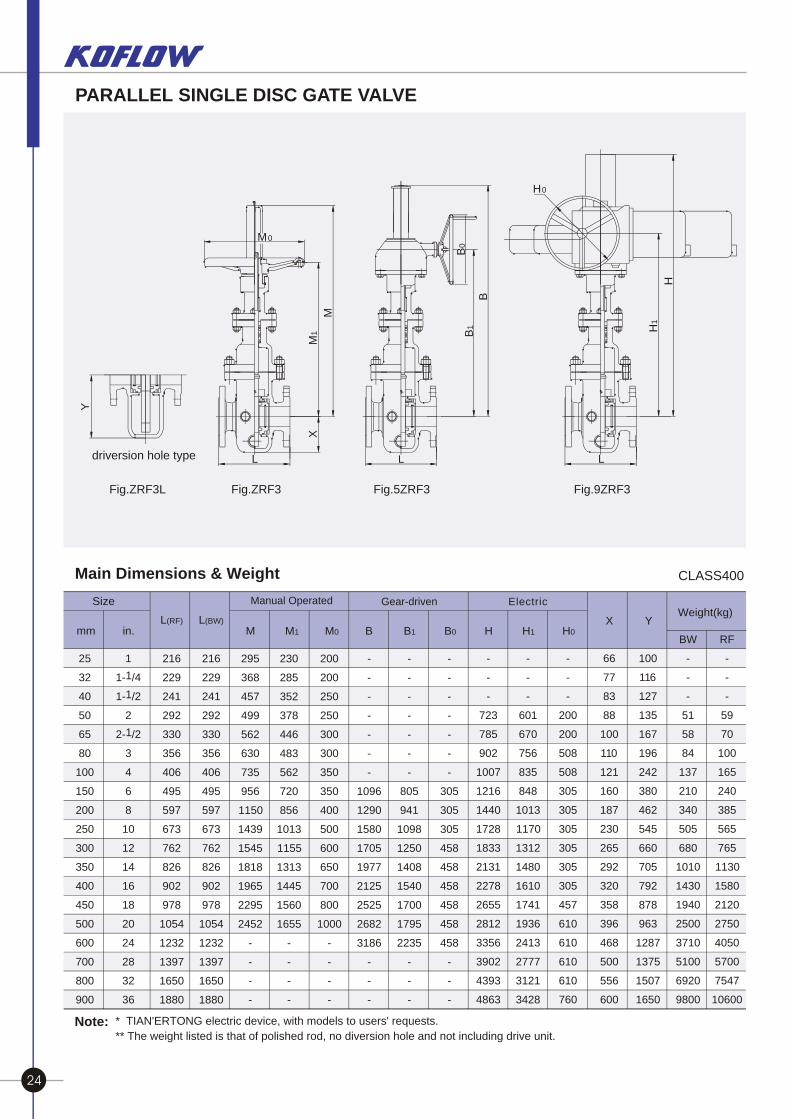
Fig.ZRF3L Fig.ZRF3 Fig.5ZRF3 Fig.9ZRF3
* TIAN'ERTONG electric device, with models to users' requests.
** The weight listed is that of polished rod, no diversion hole and not including drive unit. Note:
24 25
PARALLEL SINGLE DISC GATE VALVE PARALLEL SINGLE DISC GATE VALVE
Main Dimensions & Weight
CLASS900 PN16.0
CLASS600 PN10.0
Electric
* TIAN'ERTONG electric device, with models to users' requests.
** The weight listed is that of polished rod, no diversion hole and not including drive unit. Note:
mm in.L(RF) L(BW) X Y
Weight(kg)
M M1 M0 B B1 B0 H H1 H0
25
32
40
50
65
80
100
150
200
250
300
350
400
450
500
600
700
800
1
11- /4
11- /2
2
12- /2
3
4
6
8
10
12
14
16
18
20
24
28
32
216
229
241
292
330
356
432
559
660
787
838
889
991
1092
1194
1397
1549
1778
216
229
241
292
330
356
432
559
660
787
838
889
991
1092
1194
1397
1549
1778
295
368
457
499
562
630
735
956
1150
1439
1545
1817
1965
-
-
-
-
-
230
285
352
378
446
483
562
720
856
1013
1155
1313
1445
-
-
-
-
-
200
250
250
300
350
350
400
500
600
650
700
800
1000
-
-
-
-
-
-
-
-
-
-
-
-
1096
1290
1580
1705
1977
2125
2525
2682
-
-
-
-
-
-
-
-
-
-
805
941
1098
1250
1408
1540
1700
1795
-
-
-
-
-
-
-
-
-
-
305
305
458
458
458
458
458
458
-
-
-
-
-
-
723
821
890
995
1245
1444
1753
1858
2177
2365
2695
2922
3426
3983
4485
-
-
-
600
705
742
690
876
1013
1199
1320
1495
1762
1877
2030
2470
2835
3186
-
-
-
200
508
508
305
305
305
305
305
457
610
610
610
610
760
760
66
77
83
88
100
100
121
160
187
230
265
292
320
358
396
468
500
556
100
116
127
135
167
196
242
380
462
545
660
705
792
878
963
1287
1375
1507
BW
-
-
-
59
78
106
134
212
384
540
965
1305
1350
1950
2365
3800
5930
8333
RF
-
-
-
68
90
122
167
260
484
720
1160
1620
1800
2440
2985
4740
6800
9410
Manual Operated Gear-drivenSize
mm in.L(RF) L(BW) X Y
Weight(kg)
M M1 M0 B B1 B0 H H1 H0
25
32
40
50
65
80
100
150
200
250
300
350
400
450
500
600
1
11- /4
11- /2
2
12- /2
3
4
6
8
10
12
14
16
18
20
24
254
279
305
368
419
381
457
610
737
838
965
1029
1130
1219
1321
1549
254
279
305
368
419
381
457
610
737
838
965
1029
1130
1219
1321
1549
325
405
503
550
618
693
810
1052
1263
1583
1698
-
-
-
-
-
253
312
387
416
491
531
618
791
942
1136
1271
-
-
-
-
-
250
300
300
350
400
500
600
650
700
800
1000
-
-
-
-
-
-
-
-
-
-
833
950
1212
1423
1813
1928
2230
-
-
-
-
-
-
-
-
-
616
703
886
1037
1276
1411
1585
-
-
-
-
-
-
-
-
-
305
305
458
458
458
458
458
-
-
-
-
-
-
-
809
877
982
1098
1366
1577
1943
2058
2400
2630
2993
3147
3706
-
-
-
545
620
688
775
957
1108
1318
1453
1762
1963
2090
2168
2655
-
-
-
305
305
305
305
305
305
457
457
610
610
610
760
760
73
85
91
97
110
121
133
176
206
255
290
321
351
395
436
515
100
128
140
147
184
216
266
418
508
600
726
775
871
966
1060
1416
BW
-
-
-
-
-
-
-
421
672
983
1634
2353
2613
3575
4331
6954
RF
-
-
-
-
-
-
-
443
707
1034
1720
2476
2750
3763
4559
7320
Electric Manual Operated Gear-drivenSize
Main Dimensions & Weight
Y
driversion hole type L
X
M1
M
M0
L
B1
B
B0
L
H1
H
H0
CLASS400
Electric Size
mm in.L(RF) L(BW) X Y
Weight(kg)
M M1 M0 B B1 B0 H H1 H0
25
32
40
50
65
80
100
150
200
250
300
350
400
450
500
600
700
800
900
1
11- /4
11- /2
2
12- /2
3
4
6
8
10
12
14
16
18
20
24
28
32
36
216
229
241
292
330
356
406
495
597
673
762
826
902
978
1054
1232
1397
1650
1880
216
229
241
292
330
356
406
495
597
673
762
826
902
978
1054
1232
1397
1650
1880
295
368
457
499
562
630
735
956
1150
1439
1545
1818
1965
2295
2452
-
-
-
-
230
285
352
378
446
483
562
720
856
1013
1155
1313
1445
1560
1655
-
-
-
-
200
200
250
250
300
300
350
350
400
500
600
650
700
800
1000
-
-
-
-
-
-
-
-
-
-
-
1096
1290
1580
1705
1977
2125
2525
2682
3186
-
-
-
-
-
-
-
-
-
-
805
941
1098
1250
1408
1540
1700
1795
2235
-
-
-
-
-
-
-
-
-
-
305
305
305
458
458
458
458
458
458
-
-
-
-
-
-
723
785
902
1007
1216
1440
1728
1833
2131
2278
2655
2812
3356
3902
4393
4863
-
-
-
601
670
756
835
848
1013
1170
1312
1480
1610
1741
1936
2413
2777
3121
3428
-
-
-
200
200
508
508
305
305
305
305
305
305
457
610
610
610
610
760
66
77
83
88
100
110
121
160
187
230
265
292
320
358
396
468
500
556
600
100
116
127
135
167
196
242
380
462
545
660
705
792
878
963
1287
1375
1507
1650
BW
-
-
-
51
58
84
137
210
340
505
680
1010
1430
1940
2500
3710
5100
6920
9800
RF
-
-
-
59
70
100
165
240
385
565
765
1130
1580
2120
2750
4050
5700
7547
10600
Manual Operated Gear-driven
Fig.ZRF3L Fig.ZRF3 Fig.5ZRF3 Fig.9ZRF3
* TIAN'ERTONG electric device, with models to users' requests.
** The weight listed is that of polished rod, no diversion hole and not including drive unit. Note:
24 25
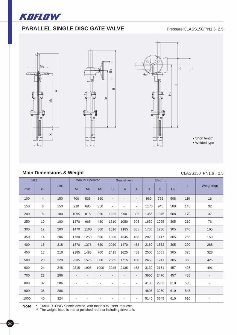
Main Dimensions & Weight CLASS150 PN1.6 2.5
* TIAN'ERTONG electric device, with models to users' requests.** The weight listed is that of polished rod, not including drive unit.
Note:
mm in.L(RF) X Weight(kg)
M M1 M0 B B1 B0 H H1 H0
100
150
200
250
300
350
400
450
500
600
700
800
900
1000
4
6
8
10
12
14
16
18
20
24
28
32
36
40
150
150
180
180
200
206
218
218
229
248
286
286
286
324
700
910
1095
1370
1470
1730
1870
2185
2335
2815
-
-
-
-
535
685
815
965
1100
1250
1375
1485
1575
1995
-
-
-
-
350
350
350
450
500
600
650
700
800
1000
-
-
-
-
-
-
1235
1510
1610
1890
2030
2415
2565
3045
-
-
-
-
-
-
900
1050
1185
1345
1470
1625
1715
2135
-
-
-
-
-
-
305
305
305
458
458
458
458
458
-
-
-
-
960
1170
1355
1630
1730
2020
2160
2500
2650
3130
3660
4135
4605
5140
795
945
1075
1095
1230
1417
1532
1651
1741
2161
2470
2933
3260
3645
508
508
508
305
305
305
305
305
305
457
457
610
610
610
110
145
170
210
240
265
290
325
360
425
455
505
545
610
16
32
37
76
105
150
288
328
425
491
-
-
-
-
Electric Manual Operated Gear-drivenSize
Short length
Welded type
B1
B
B0
L
H0
H1
H
L L
X
M1
M
M0
PARALLEL DOUBLE--DISC GATE VALVE
Design characteristics of Parallel Double-Disc Gate Valve
Intensively structured stem nut and lubricator make operation easy and flexible. .
Packing spacer ring can be mounted in packing if requested by users, and it can be injected with sealing grease to ensure the dependable seal and lubrication of valve stem. .
Back the conditions of high temperature and high pressure, the disc at inlet side may be designed to pressure relieving type to avoid the abnormal pressure rise inside the cavity resulted from temperature changes, thus to ensure safe operation. .
When valve is fully opened, passage is a straight pipeline, with little fluid resistance and pressure loss to allow hair bulb to clean the pipeline. .
The valve uses a seal structure composed of two parallel discs and wedging device instead of the conventional wedged gate valve structure. .
The parts in valve sealing mechanism are isolated from each other, thus to ensure good sea l even upon deformation resulted from temperature variation, and that disc cannot be jammed due to high temperature expansion. .
Middle flange uses metal waveform gasket to ensure dependable seal. .
Two-piece design of packing gland to avoid stem clogging caused by squishing. .
Valve is fully enclosed for good protection and all-weather service. .
1 Type of end connection referred to Appendix
2 Type of disc structure referred to Appendix
3 Structure of packing spacer ring referred to Appendix
4 Valve operation referred to Appendix
Remark:
PARALLEL SINGLE DISC GATE VALVE Pressure:CLASS150/PN1.6~2.5
26 27


