‘\luly 29. 1924. _ I 0 1,503,300 ' E. C. CLARK ET AL - . AUTOMATIC FILM WINDING CAMERA Filed Dec. 15‘, 1922 5 Sheets-Sheet l 921 q I INVENTORS [2/34 6‘ CZARK _ Jam/F POLHEMVJ ' BY _ , J3 / ' ATT NEY
Transcript
‘\luly 29. 1924. _ I 0 1,503,300 ' E. C. CLARK ET AL - .
AUTOMATIC FILM WINDING CAMERA
Filed Dec. 15‘, 1922 5 Sheets-Sheet l
921 q I
INVENTORS [2/34 6‘ CZARK _ Jam/F POLHEMVJ
' BY _ ,
J3 / ' ATT NEY
July 29 , 1924. 1,503,300 E. C. CLARK ET AL
"AUTOMATIC FILM WINDING CAMERA
Filed Dec. 15 , 1922 5 Sheets-Shéet 2
7
F9. 7. ‘ ‘INVENTORS EZRA vC CLARK JOHN F POLH£M(_/5
'J?ly 2919 1924.‘
40 56
70 77 47
26
Jul.
E. c, CLARK ET 1,503,300 AL
AUTOMATIC FILM WINDING CAMERA ‘
‘. Filed Dec. 15, 1922
‘82 51
tigrij' |
5 Sheets-Sheet 3 v
Fig.4 INVENTORS
£224 a‘ CLARK JOHN F POLHEMl/S BY
% a a, ATTEY
> " . 1,503,300 E. c. CLARK ET AL
AUTOMATIC FILM WINDING CAMERA
Filed Dec. 15 , 1922 5 Sheets-Sheet 4
I ' - ’ INVENTORS
J6 '53? ’ EZRA C CLARK '
BY _ _
wf/ .0 ATT N EY
July 29. 1924. 1,503,300 ' E. c. CLARK ET AL
AUTOMATIC FILM WINDING CAMERA
Filed Dec. 15, 1922 5 Sheets-Sheet 5
5
15
20
25
30
, tive compensating nieei-i'is'htis been p'i‘ovided
35
40
4
50
Patented July 29, 1924.
"LFNETE it stemseet _ isessee
m“ eseiee, EZRA c. CLARK, ‘0F BINGHAMTON, AND JOHN F. PotHEstUs, 0F troiilvsoiw CITY, iiEW
Yo-RK, ASSIGNORS, BY MESN'E ASSIGNM NEW YORK, N; Y.-, A CORPORATION OF Ems, To ensco rnoti‘ornbiitrows, 1110., OF NEW YORK.
AUTOMATIC FiLM-W'I-NZUING CAMERA.
Be it known‘ that We, EZRA ‘C. Omit}; and J OHN F.- Pommms, both citizens of the Ui'iite‘d States, andre‘siderits, respectively, of the city of Bivng‘haiht’on, coiuit'y of 1315061116, and Stete‘ of New York, and John so'n City, cottinty of Bi‘ooine, aiid State of New York, have i?vented eerteinv'new and useful,‘linproyeiiiehts in‘ en ‘Aiitom‘atic Fili?e‘llviiidihg Camera, of which the follow ing’is a‘ description, refefenceheing had to the accompziilying drawings, in which like reference‘ iiiimerals indiczite?like‘ parts. This iii‘vehtio‘il iielate‘s particulai'lylto' that
type of cali'heifew'li'ereiii the strip of sensi tized ?liii is etit'omatically 'sliiftedvafter (each operation of the camera to‘ iiiétke an ex‘ posure 011' said ?lm, thus placing- an iiii'e'x posed portion‘ ofthe ?lm into position for the next exposure. By this method of Opf eréttioh, which is vcon‘ti'olleol entirely by the I shutter acttititing' mechanism of the ‘camera, do'tihle exposures oil a single section of ?lm ate completely avoided; else‘ the necessary hen'd winding of the ?lm is eliminated which essui‘es ihiich ‘greater speed in‘ the operation of the céimer‘a. , ' _ '
rHeretofore the principal objection‘ to ‘cameras ‘of the automatic ?lm winding type has beeii‘ the fact that no adequate ahd posi
for the iii‘e‘chzinishi which di‘ites' the take up spool of the ean'iei'a to Win'd’the ?lm .thei‘eon. ‘ The diameter of the take up spool varies as the ?lm‘ is Wotiiid theiie'o‘ii, therefoi'e‘. some n‘iean's miist be provided to compensate for such Vai‘yihg' diéi‘i'iietef of the spool, in order thztt thesaiil'e leiigth e13 ?lm Will be dra'?irii
‘ across the exposure chétiiiher at each opera‘ tion‘ of the device; is . 7
It is the pi'incip‘al object of this in‘tieiitioil therefore‘, to‘ provide the automatiewind'ing ine'chenishi with a coinp’eii'séttol" fo‘i' posi tiveljf and acciii‘etely causing » {deform leiigths of ?lm to be suecessively '?os‘itiotlied for expesure. It is 2% fiii‘the'f é’hj'éét ‘of our iiii'eiitio‘il to proviee, the ,iiio‘toi" di‘iveh ‘mechanism of this‘, device with a go'i'ier’ 0&1 to regulate the speed of the motor‘ aiidkeep the saline unifdnii throiig‘hoiit its“, ép‘e'iat‘io?. It is very esse?tiéilt'o the pfét‘c‘ti'c‘al op’e i1» tion of this‘ type of miner , that some i?esiis he‘ p'i'oi/‘ided fol" this“ put-‘page and We be‘ l-iei/‘e' theft have dé'il?éd 9L Iidi’él Eiiid ie'i‘jf
~ ‘ Apblicétioii iiled December 15, 1922. Serial No. 607,246.
practical type ,ef governor, which is es: pecially adapted forthi's sei‘vice'. , s n ,A third object is the provisioii of device fof iiisuriiig‘ the operation of the releasing mechanism~= Itv has very fi*eqiieiitly oe ciu‘i‘ed iii the operatioii of ti gamers ofthis c'hei'a'eter that due to the qiii’cik ecti'o'fiof the re easing iiieéin's, the releasing pawl Will snap‘ back into festiraining' positioi'i before the motor has 'stzii‘ted the winding i'?echa ii'ishi. ,We have, thei'efofe, ,pi‘ovided 21 del vvice which cooperates With the i‘elea‘sing 21nd resti‘ainin'g ,iheans to coiiipel c'o'i'np'lete ‘operation ofthe'seme. , , 1"
It 1s a stlll fiirthet obye‘ct ofour lnven ‘tion' to provide etii' improvedstop' device forthe di‘iving‘ inechéi?ij‘siii, and to associate ,tvith the same it hovel idem ofvre ea'si?g means which 'is actuatedv ai‘itoiii'ztticztlly at each opei‘z'tti'o‘h of the shutter ihe'chaiiisin; _ ,
k Our‘ invention is'rxztn improvement upon that patented iii‘ Lahfclhfy United States‘ Let ters Patent No‘. 1,197,901, déite'd Sept'e'ihher 12,, 1916; No. 1,215,543, dated Feb‘ftiefy 20, 1917,; and No. 1,268,805, dated Julie 4, 1918, till issued [to Ansco Company es,_'t11’e,,as_
of constructioii and oper'a‘tion Will be ap p'zii-ent {is the deseript-ion pi‘ocee'ds, ljefe'i'ence Being had to the zi'c'co‘ii‘ipaiiyingj drawings Whe‘fei? like iiefei'en'ce' iiiiiiierétls indicate
In the drawingsa . ' _ V
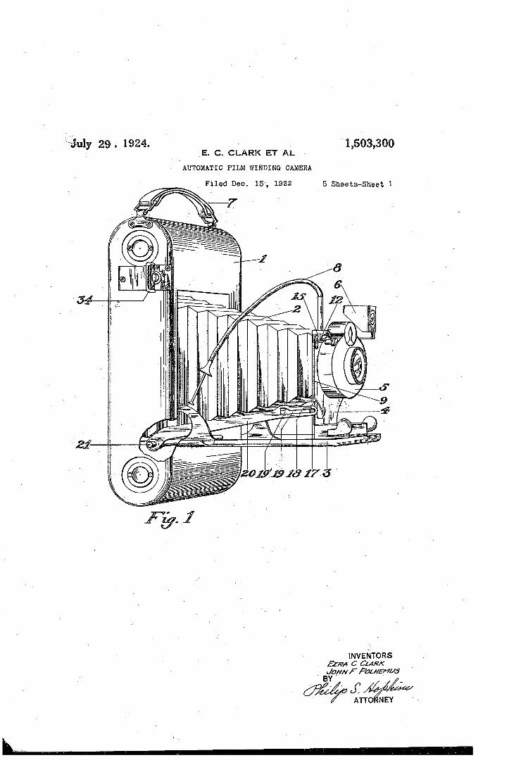
Figiiiiie l is a peiisp‘ectivevieiw‘f ‘of a camera of the character described, ‘ ~ shoitrihg‘i the 'ineehgi?isin for eoh-tijolling the operation of it ie. ‘shutter and of: the ?lih wliidlng injechtt nisin, certain parts being b'ir‘o‘k'e'h may to’ show details of consti‘iic'tioii. Figure 2 1s fto‘nt View oflthe cz‘iinera is its 1301
ijfiniery eerie-ting parts when the‘, Cilll?éféi is iii‘ its closed pdsities; éilso iii thisi?g‘iil‘e a‘ sectio'ri oh the side of‘ the genie 5 lies been removed to show inv side ele’iialtio‘h the ?lhi Win‘diiig ine'c'hzniis'riii ' Fig-me 3 is .a'1 rear‘ View‘ of the camera
with the’ hack and side re‘iiioiied thefeffoi'h and i'v'ith ,p‘zifts broken awziy showing de t'ziilsl (if éUhsttiidtio’n of ‘the meter and the ?iiiidiiig" iheeli?iiistih. '
55
60
65
75
80
35
95
ded fp'olsiit'io'n and with the from; h'ozird lo’we'fedto show thepositionv of the
100
' Q
Figured is a side view of the camera with the cover removed showing the complete as sembly of parts which make up the winding mechanism. ~ '
,Figure 5 is a detail side view showing the ~ gear train which drives the operating parts
10
of the Winding mechanism. Figure 6 is a view similar to Figure 5
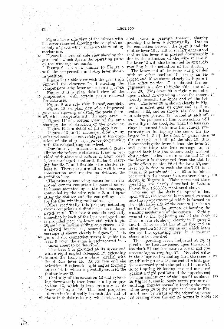
with the compensator and stop lever shown in position. Figure 7 is a side view with the gear train
‘ removed for clearness in illustrating the
es , enlarged scale successive stagesin the oper~
compensator, stop lever and operating levels. Figure 8 18 a plan deta1l.v1ew"of the
compensator, with certain parts . removed ' for clearness. ,
' Figure 9 is a sideyview thereof, complete. Figure 10 IS a plan view of our improved
governor showingin detail the parts there of, whichcooperate with the stop lever.
Figure‘ 11 is a bottom view of the same showing the construction of the governor. Figure12 is ‘a detail of the stop lever. F1guresl3 vto 16 inclusive show on an
ation oifthe stop lever pawls cooperating with the notched ring and wheel. Our improved camera is indicated gener—.
ally bythe reference character 1, and is pros ‘ ‘vided withthe usual'bellows 2, front board
8, lens carriage 4', shutter 5, ?nder 6, carry ing handle 7 , and ?exible wire shutter re lease 8; These parts are all of well known construction and require no detailed de scription here. The primary actuating means for our im
proved camera comprises in general an at tachment mounted upon the lenscarriage, controlled by the wire release 8, and oper ating the shutter and the controlling lever for the ?lm winding mechanism,’ More speci?cally this primary actuating
means comprises a sliding bar or lever desig vnated at 9.‘ This bar 9 extends vertically
c0,
65
immediately back of the lens carriage 4 and is provided near its lower end with a pin 10, said 3111 having sliding engagement with a slotted bracket 11, secured to the lens carriage as shown clearly in ?gure 2. This pin and slot connection serves to guide the lever'9 when the same is reciprocated in a manner‘ about to be described. ' The lever 9 is provided at its upper end
with a right angled extension 12, extending toward the front to a plane parallel with the shutter lever 13; At its free end the extension 12 isbent at right angles forming
, an ear 14, to which is pivotally secured the shutter lever‘13. ‘ .
‘Centrally of the extension 12 and extend ing downwardly therefrom is a lip or pro jection 15, which is bent inwardly at its lower end ‘as at 16._ This bent projection 16 terminates directly‘ beneath the end of the wire shutter release 8, which when oper
1,503,300
ated exerts a pressure thereon, thereby 'pr'essingthe lever 9 downwardly. Due to the connection between the lever 9 and the shutter lever 13 it will be readily understood that as the lever 9 is pressed downwardly “ due to the actuation of the wire release 8, the lever 13 will also be carried downwardly resulting in the actuation of the shutter. The lower end of the lever 9 is provided
with an offset portion 17 having an en— larged end 18 as shown clearly in Figure 1. This offset portion 17 is adapted for en gagement in a slot 19 inthe outer end of a lever 20. This lever 20 is rigidly mounted upon a shaft 21'extending across the camera directly beneath the inner end of the bel lows. The lever 20‘ as shown clearly in Fig ure 2 isotl'set near its outer end as illus trated. at 22, and as shown, the slot 19 has an enlarged portion 19’ located at such ott set The purpose of this construction will be readily understood, for when the lens car_ riage is pushed back into the camera pre paratory to folding up the same, the en larged ‘end 18 of the offset 17 passes thru the enlarged end 19’ of the slot 19, thus disconnecting the lever 9 from the lever 20 and permitting the lens carriage to be pushed back into the camera body without obstruct-ion. Also as soon as the end 17 of the'lever 9 is disengaged from the slot 19 in the offeset portion 22 of the lever 20, said lever 20 is ‘free to rock the shaft 21 in a manner to permit said lever 20 to be folded back within the camera in a manner clearly shown in Figure 2. These parts and their operation are clearly described in Letters Patent ‘No. 1,268,805 mentioned above. The end of the shaft 21, opposite that
upon which .the lever 20 is mounted, extends int) the-compartment 23 which. is formed on the right hand side of the camera (as shown in Figure 2) for the purpose of housing the windingmechanism of the camera. Rigidly secured‘ to this projecting end of the shaft 21 is an arm 24-, shown clearly in Figures 3 and a. This arm 24: has at its free end an offset portion 25 forming an ear which bears against the operating lever in a manner about to be described. This operating lever, indicated at 26, is
pivoted for free movement upon the end of the shaft 21 and has near its lower end two upstanding bearing lugs 27. Mounted with in these lugs and extending thru the same is an adjusting screw 28, one end of which pro jects outwardly into the path of the car 25. A coil spring 29 having one end anchored against a rigid post 80. and the opposite end bearing against one of the lugs 27 as shown in Figure 4:, continuously exerts pressure on said lug, thereby normally forcing the oper ating lever 26 to the right as shown in Fig ure 4:, and by virtue of the adjusting screw 28 be ring upon the ear 25 normally holds
80
95
101)
105
110
120
130 -
1,503,300‘
the shaft 21 in such position as to cause the lever 20 to be slightly raised in position to engage the end 17 of the sliding bar 9, and as will be readily understood, such position can be adjusted to varying degrees thru the operation of the adjusting screw 28. Because of the construction just described '
it will be seen that the great simplicity in arrangement of parts provides an efficient and easily operated camera attachment, which in no way interferes with the ordinary or regular operationof the camera. “Then the lever 20 is folded back into the camera into the position shown in Figure 2, the shaft 21 is rocked in its bearings,and the arm 24 at the opposite end thereof, assumes the position shown in dotted lines in Fig ure 4. . i .
Referring now to Figure 3, it will be seen that the motor for driving the winding mechanism is located entirely within the
'7 camera directly beneath the take up spool.
cs (Jl
p. m
.69
It may be covered over with any suitable covering, such as a metal casing which con ceals the same and renders it dustproof. The motor used in this’ camera, and which is the preferred form because of its'small ness in size and adaptability to the conven tional type of cameras, is the-same as that shown and described clearly in Letters Pat ent No. 1,197,901, above mentioned and com prises generally an ordinary spiral spring indicated at 31, and a smaller spiral spring’ indicated at 32 ?tting telescopically within said spring 31. A shaft 33'6Xt611ClS thru these springs and is attached thereto in the‘ manner clearly described in the-before men tioned patent. Suliice it to say here that such motor is provided with a winding key 34,- and a pawl and ratchet device 35 at one end, and at the opposite end with a driving gear 36, the arrangement‘ of these parts be- 7 ing such that upon the manual rotation of the winding key 34, the spring motor is thereby placed under tension and so held by ‘the. pawl and ratchet device 35, inmuch ‘the same 'manner of operation as the ordinary clock spring. The function of this motor is of course to drive the take up spool of the camera to wind the ?lm thereon. ' The driving gear 36 of the motor shaft < 3
meshes with a pinion 37, journaled at 38 on the base plate 39. This base plate extends ' lengthwise alono' theside of the camera and upon the same is mounted the gear train and other mechanism, which drives the take up‘ spool. . 9
Rigid with the gear 37 is a larger gear 40, the teeth of which mesh with a pinion '41» mounted upon the driving trunnion 42 of the take up spool 43. The operation of this gear 41 together with the operation of its cor related parts, including ' a manually con— trolled winding key 44 and pawl and ratchet connection, between the shaft 42 and gear 41,
3
is clearly described in the above mentioned Letters Patent N 0. 1,197,901 and therefore needs no detailed description herein. It will be understood of course that. such con struction permits of rotating the take up spool 43, which is removably trunnioned on said shaf‘ 42, by a conventional key and slot arrangement, by manual manipulation of the winding key 44, independent of the mo tor ‘driven mechanism, and also provides for the rotation of said shaft in the same direc tion thru the medium of gears 36, 37, 40 and 41. Because of the extraordinary strength of
the motor required to wind the film upon the take up spool it is essential that some means be provided for regulating the speed of such a motor. lVe have therefore, provided a 'governorfor this purpose which is driven from the motor by a train of gears as fol—
45, journaled on the base plate 39 at'46, which pinion carries a larger gear 47 mesh ing with a pinion 48, journaled at 49, and, carrying the gear 50, which-1n turn meshes- with pinion 51, j ournaled at 52 and carrying the gear 53. The gear 53 meshes with and drives the small pinion 54, which is rigidly secured to a rotatable disk 55'. As shown clearly in Figure 11 this disk 55 has loosely pivoted thereon three small levers'indicated at 56, 57, and. 58. The disk 55 is'journaled at59 and acts as a rotatable top for a small circular housing 60 into which the pivoted levers 56, 57, and 58 extend. It will be; readily understood that as the disk 55'is ro tated thru the medium of gear 54, the free ends of the said levers secured to the disk will be thrown outwardly thereon by centrif- ' ugal force and will bear against. the inner wall of the housing 60. The ‘greater the speed of rotation of the disk 55, the greater the force with which said levers will bear against the wall of the housing 60 and thus govern the speed of the driving mechanism. This type of governor is'especially to- be preferred over the familiar escapement type or other forms because of its smallness and particularly because of its quietness in oper ation. ' p
Also rigidly secured to the disk 55, be tween the gear-54 and said disk, is a wheel 61 having two oppositely directed teeth or stops indicated at 62 and 63. The purpose of this disk 61 will be more fully described as the description proceeds. The compensating mechanism heretofore
mentioned is comprised as follows: Loosely mounted upon the hub 38 of gear 40 is a wheel 64 having internal gear teeth 65 and provided in its outer periphery with un evenly spaced notches ‘66. Superimposed upon the wheel 64 1s a ring 67, also having unevenly spaced notches 68 in its outer oe riphery, said notches being slightly 0‘
75
'85 lows: The gear 40 meshes with the pinion. '
90
100
105
110
115
.120
125
10
15
25
.30
45
50
60
65
Mb
from. the notches 66. The purpose o't‘ this ring 6'? will be described later.
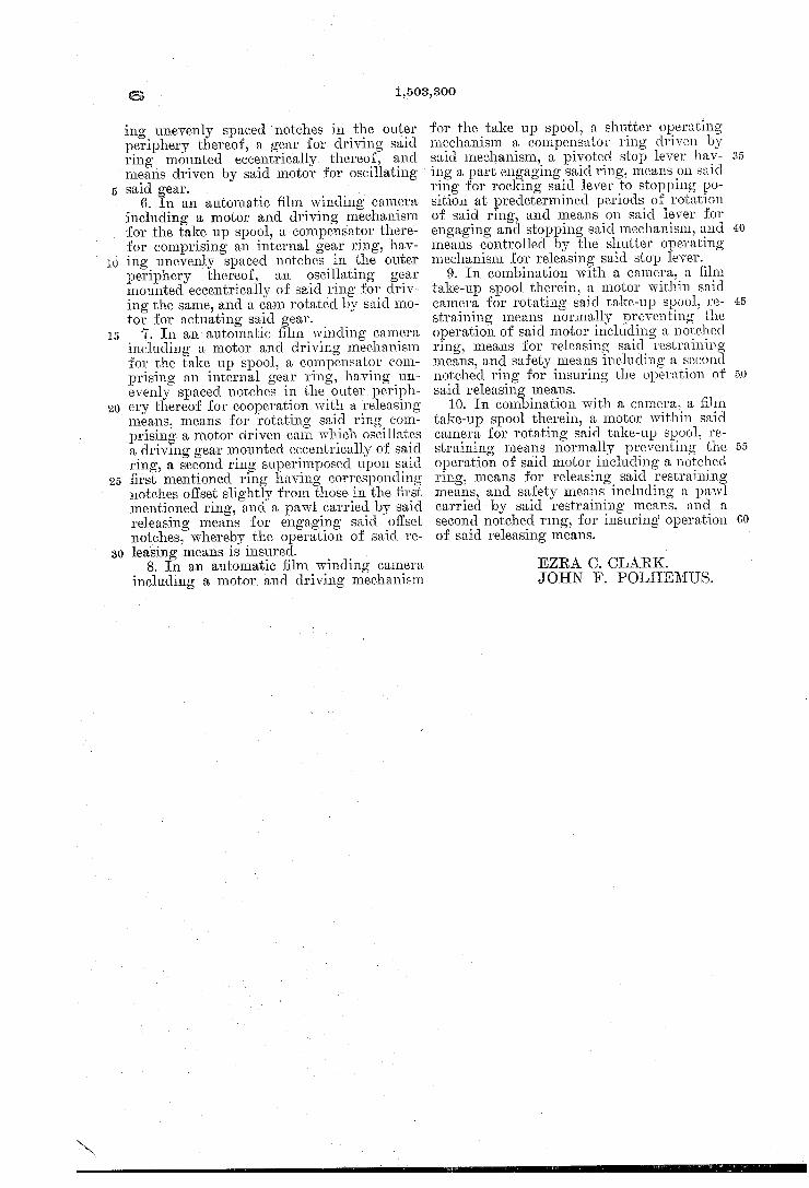
Carried by the gear 40 and mounted ec centrically of the center thereof is a cam 69, which is eccentrically mounted upon and rotates with the gear 40. Loosely mounted around the cam member 69 is a gear 7‘), the teeth of which mesh with the internal gear teeth 65 of the wheel 6%. Mounted upon the gear 70 is a guide plate 71 (shown clearly in Figure 8), the free end of which is provided with a slot 72, which engage with and is guided by the journal pin 46. It will be readily understood that upon ro tation oi”: the cam 69, an oscillatory move ment will be imparted to the gear 70 which, guided ‘by the slot 72 sliding on the post as, will bring the teeth of said gear into mesh with the internal gear till-,causingthe same to rotate slowly. As shown in Figures L1, 6 and 7, the ring 67 is provided with the numerals 1 to 12 inclusive. These numerals are spaced apart ‘in. accordance with the un ven spacing of the notches 68. suit able window or peep/opening may be pro vided in the cover 73 which encloses the driving mechanism, and which may be re movably secured to the camera in any con ventional manner in order to provide ready access to such mechanism. This peep hole (not shown) may be so positioned that the numerals above referred to will appear successively thereunder and thus indicate to the operator the number 0t exposures al ready taken and the number left on his ?lm. Such an arrangement is clearly shown and described in the above mentioned Patent No. 1,197,901. For the purpose of rel-easably holding the
driving mechanism from operation. there is provided a stop lever 74, shown in detail in Figure 12, and in operative position in Figure 6. The stop lever 7% is pivoted to the base plate 39 at 75, and has at its upperv end a nose or dog 76 for engaging the notches 66 of the compensator wheel 64-. The nose 76 is normally held against the wheel 6:1 by means of a coil spring 77 hav~ ing one end thereoii attached to the lower extremity of the stop lever 74-, as at 78, and the other end anchored to the cover plate 79, which, as shown in Figure 4}, is spaced from and secured to the base plate 39. Near the lower end of the stop lever 74 there is provided a shoulder 80. which, due to the action of spring 77. is normally pulled into engagement with one of the teeth of the stop disk 61. A slot 81 is provided at the lower end of stop lever 74-, which slides on a pin 82, mounted ‘on a base plate 39. for the purpose of guiding the lever 74. A guide arm 82’ is formed at the upper end of the stop lever and bears against a guide pin 83. Pivotally mounted at 84 on an up standing arm 85 of the lever 74, is a pawl
1, 503,300
86, which is normally held in the position shown in Figures 4 and 7, bearing against a stop pin 87, by means of one end of coil spring 88. A second pawl 89 is piv
oted at 90 upon the upper end of the lever ‘Til, and said pawl is provided with a nose 91 'lt'or engagement with the notches 68 in the ring 67. The nose 91 is normally forced into engagement with the ring 67 by the opposite end of the spring 88 as shown clearly in Figure 4. A stop pin 89’ is provided on the lever 74 which limits the movement of pawl 89 in one direction. Pivoted upon the cover plate 79 is a pawl
92, one end of which is notched as at 93 for the reception of the upper end of the operating lever 26. A dish 9% holds the pawl 92 on the plate 79. The nose of the pawl 92 is so located as to engage the pawl 86 and to move the same when motion is imparted to the lever 26 thru the shaft 21. The operation of the mechanism described
is as "follows: The operator of the camera having ?rst inserted a roll of ?lm in the supply spool'chamher 95, and having at tached the free end of the ?lm to the take up spool 43, then rotates the said take up spool 48 by hand thru the medium of. the winding key 4A until the usual ?gure “1’7 printed on the black paper covering of the film, appears beneath the usual peep hole in the back of the camera. The nose 7 6 of the lever 74 should be positioned within the ?rst of the series of notches in the ring 64. The spring motor should be wound tightly by turning the winding key 361-, and then with the camera opened and lens carriage pulled out in the proper position, the camera is ready for operation. The operator ?nds his subject- in the ?nder 6 in the usual manner and presses the wire release 8. This con veys a downward motion to the sliding bar 9, and upon such downward motion the shut ter will be operated thru the medium of the connection between the shutter lever 13, and the upper part of the bar 9. The downward motion of the bar 9 also rocks the lever 20 downwardly and consequently the shaft 21. Such movement of the shaft 21 brings the lip 25 of the lever 2d into engagement with the adjusting screw 28, and thru this rocks the lever 26 to the left (in Figure 4) against the tension of the spring This move ment to the left, of the lever 26.v rocks the pawl 92 upon. its pivot causing the same to snap past the pawl 86, said pawl 86 being returned to the position shown in Figure 4 by the action of the spring 88. XVhen the op erator releases his pressure on the wire re lease 8, the lever 26 will be thrown back to the right by the spring 29, such movement causing the pawl 92 to engage the upper side of the pawl 86 and force the same to the left (in Figure ll). Because of the pawl 86 hearing against the pin 8'7 on the stop
70
75
85
90
100
165
110
115
15
1,503,300
lever 74 the movement of the pawl 86 is thus lmparted to the lever 74-, which, rock 1ng upon its pivot 75, disengages the shoul~ der 80 from the stop dislr 61 and also the V nose 76 from the notch 66 in the ring 64. This permits the spring motor to exert its force on: the’ train of gears and thus to ro tate the take up spool until the next notch in the compensator ring6e reaches the nose 76. As soon as the ring 64 has moved Su? cient distance to‘bring the ‘next notch to the nose 76, said nose will immediately‘ drop into the notch thus permitting the lever 74 to rock on its pivot, due to the action of spring 77 and thus bring the shoulder 80 into path of the teeth 62 and 63 on the stop disk 61. It may be noted here that by po~ sitioning the stop disk 61 and the cooperat ing shoulder 86011 the stop‘ lever, remote from the motor or the source, of power we have lessened to a marked degree the shock
V which necessarily results from a sudden
ill)
cn GI
60
stopping of the, action of the motor; also that by correlating the stop disk 61 and the governor we'have simpli?ed this mecha nism and provided for a more uniform and positive stop action than has hitherto been utilized.
It is well known in cameras of this char acter that due to therapid’snapping action by which the cameras are operated, fre quently the releasing mechanism does not have time to release the motor and permit the winding of the ?lm. In other words the releasing movement is so rapid that it often happens that the releasing mechanism snaps back into restraining position before the motor has had time to start its winding movement. To overcome this di?culty we have provided the pawl 89 and the ring 67. It will be noted by reference to Figure 4 that upon‘the movement of the lever 74 to' withdraw the nose 76 from its notch 66, the nose 91 of the pawl 89 is also being with drawn from its corresponding notch 68, which as shown, is slightly in advance of the corresponding not-ch 66. As soon as the nose 91 is withdrawn from its notch the spring 88, forcing the same towards the right in Figs. 4 and 7 until the tail of the pawl 89 engages the pin 89’ causes said nose 91 to engage upon the periphery of said ring 67 between the adjacent notches. Therefore as soon as the‘ nose 91 engages upon the pe riphery of the ring 67, instantly upon the operation of the lever 74, the nose 76 is pos itively withheld from returning into its notch 66 until the compensator ring has been started by the action of the motor. Also due to the offsetting of the notches 66 and 68 the pawl 89 first drops into its corre sponding notch thus relieving the pressure on the lever 74. and leaving the spring 77 free to pull the nose 76 into its proper notch when the, same is presented. It will thus
S
be seen that we have provided a novel and positive means for insuring the operation of the releasing mechanism when the same is actuated. V
In conclusion, we believe we have here de 70 scribed and illustrated a novel, and practical . automatic ‘?lm winding camera, provided with simple e?icient and accurate compen sating means, and a desirable type of gov ernor for rendering such a camera service able for speedy and unfailing use. ‘While the embodiment shown and described herein is the preferred form of our invention, it is to‘ be understood of course that’ the same is sus ceptible to many changes in details of con struction and parts, and’ we do not limit our selves therefore to the exact form shown other than by the appended claims. lVe claim— .
1. In combination with camera a ?lm take up spool therein, a motor within said camera for rotating said spool, a train of gears connecting said motor and said spool, a‘stop mechanism operating upon said gear train for automatically stopping said motor after‘ a predetermined rotation of said spool, a compensator controlling said stop mecha nism comprising an internal gear ring hav ing unevenly‘, spaced notches‘ in the outer periphery thereof with which said stop en gages. I
2. In combination with a camera, a film take up spool therein, a motor within said camera for rotating said spool, a train of gears connecting said motor and said spool, a stop mechanism operating upon said gear train for automatically stopping said motor after a predetermined rotation of said spool, a compensator controlling said mechanism comprising an internal gear ring having unevenly spaced notches in the outer periphe ery thereof, with which said stop engages, said compensator being driven by an eccen tric gear from said motor. ‘
3. In combination with a camera, a film take up spool therein, a motor within said camera ‘for rotating said take up spool, means to compensate for the varying diam eter of said spool as the film is wound there on comprising a gear ring having unevenly spaced notches on the periphery thereof, said gear ring being driven by said motor thru a cam driving an internal gear mount ed eccentrically to said gear ring.
4. In an automatic ?lm winding camera including a motor and driving mechanism for'the take up spool, a compensator there for comprising an internal gear ring having unevenly spaced notches in the outer periph ery thereof, and means driven by said motor for rotating said gear ring.
5. In an automatic ?lm winding camera including a motor and driving mechanism’ for the take up spool, a compensator there for comprlsmg an internal gear ring hav
75
90
100
105
110
115
13-1)"
20
30
@
ing unevenly spaced notches in the outer periphery thereof, a gear for driving said ring mounted eccentrically thereof, and means driven by said motor for oscillating said gear.
6. In an automatic ?lm winding camera including a motor and driving mechanism vfor the take up spool, a compensator there for comprising an internal gear ring, hav ing unevenly spaced notches in the outer periphery thereof, an oscillating gear mounted eccentrically of said ring for driv~ ing the same, and a cam rotated by said mo tor for actuating said gear.
7. In an automatic ?lm winding camera including a motor and driving mechanism for the take up spool, a compensator com prising an internal gear ring, having un evenly spaced notches in the outer periph— ery thereof for cooperation with a releasing means, means for rotating said ring com prising’ a motor driven cam which oscillates a driving gear mounted eccentrically of said ring, a second ring superimposed upon said ?rst mentioned ring having corresponding notches o?set slightly from those in the ?rst mentioned ring, and a pawl carried by said releasing means for engaging said offset notches, whereby the operation of said re leasing means is insured.
8. In an automatic ?lm winding camera including a motor and driving mechanism
1,503,300
for the take up spool, a shutter operating mechanism a compensator ring driven by said mechanism, a pivoted stop lever hav ing a part engaging said ring, means on said ring for rocking said lever to stopping po sition at predetermined periods of rotation of said ring, and means on said lever for engaging and stopping said mechanism, and means controlled by the shutter operating mechanism for releasing said stop lever.
9. In combination with a camera, a ?lm take-up spool therein, a motor within said camera for rotating said take-up spool, re straining means normally preventing the operation of said motor including a notched ring, means for releasing said restraining means, and safety means including a second notched ring for insuring the operation of said releasing means.
10. In combination with a camera, a ?lm take-up spool therein, a motor within said camera for rotating said take-up spool, re straining means normally preventing the operation of said motor including a notched ring, means for releasing said restraining means, and safety means including a pawl carried by said restraining means, and a second notched ring, for insuring‘ operation of said releasing means.