13 Fin-Tube Heat Exchanger Optimization Piotr Wais Cracow University of Technology, Department of Thermal Power Engineering Poland 1. Introduction Saving material and energy are common objectives for optimization. One of the important issues that should be defined during the design work, taking in consideration the cost of material, is the optimization of the heat efficiency. The optimization function can consider minimum weight for a specified heat flow, placement of individual fins to form channels or fin profile based on a set of specified conditions (for instance the dissipation from the fin faces, minimum mass, minimum pressure drop etc). In order to intensify the heat transfer from the heat exchanger surface to fluid, it is possible to increase convection coefficient (by growing the fluid velocity), widen temperature difference between surface and fluid or increase the surface area across which convection occurs. Extended surfaces, in the form of longitudinal or radial fins are common in applications where the need to enhance the heat transfer between a surface and an adjacent fluid exists. Fins are commonly used in extended surface exchangers. Conventional fin-tube exchangers often characterize the considerable difference between liquids’ heat transfer coefficients. In a gas-to-liquid exchanger, the heat transfer coefficient on the liquid side is generally one order of magnitude higher than that on the gas side. To minimize the size of heat exchangers, fins are used on the gas side to increase the surface area and the heat transfer rate between the heat exchanger surface and the surroundings. Both the conduction through the fin cross section and the convection over the fin surface area take place in and around the fin. When the fin is hotter than the fluid to which it is exposed then the fin surface temperature is generally lower than the base (primary surface) temperature. If the heat is transported by convection to the fin from the ambient fluid, the fin surface temperature will be higher than the fin base temperature, which in turn reduces the temperature differences and the heat transfer through the fin. Exchangers with fins are also used when one fluid stream is at high pressure. The temperature value is limited by the type of material and production technique. All above causes that finned tube heat exchangers are used in different thermal systems for applications where heat energy is exchanged between different media. Applications range from very large to the small scale (tubes in heat exchangers, the temperature control of electronic components). The subject, which is investigated in the chapter, is inspired by the increasing need for optimization in engineering applications, aiming to rationalize use of the available energy. The performance of the heat transfer process in a given heat exchanger is determined for different fin profiles, considering the fluid flow as a variability often neglected for the fin optimization. The optimization task, defined in the chapter, is to increase heat transfer rates and reduce the www.intechopen.com
Transcript
13
Fin-Tube Heat Exchanger Optimization
Piotr Wais Cracow University of Technology, Department of Thermal Power Engineering
Poland
1. Introduction
Saving material and energy are common objectives for optimization. One of the important issues that should be defined during the design work, taking in consideration the cost of material, is the optimization of the heat efficiency. The optimization function can consider minimum weight for a specified heat flow, placement of individual fins to form channels or fin profile based on a set of specified conditions (for instance the dissipation from the fin faces, minimum mass, minimum pressure drop etc). In order to intensify the heat transfer from the heat exchanger surface to fluid, it is possible to increase convection coefficient (by growing the fluid velocity), widen temperature difference between surface and fluid or increase the surface area across which convection occurs. Extended surfaces, in the form of longitudinal or radial fins are common in applications where the need to enhance the heat transfer between a surface and an adjacent fluid exists.
Fins are commonly used in extended surface exchangers. Conventional fin-tube exchangers often characterize the considerable difference between liquids’ heat transfer coefficients. In a gas-to-liquid exchanger, the heat transfer coefficient on the liquid side is generally one order of magnitude higher than that on the gas side. To minimize the size of heat exchangers, fins are used on the gas side to increase the surface area and the heat transfer rate between the heat exchanger surface and the surroundings. Both the conduction through the fin cross section and the convection over the fin surface area take place in and around the fin. When the fin is hotter than the fluid to which it is exposed then the fin surface temperature is generally lower than the base (primary surface) temperature. If the heat is transported by convection to the fin from the ambient fluid, the fin surface temperature will be higher than the fin base temperature, which in turn reduces the temperature differences and the heat transfer through the fin. Exchangers with fins are also used when one fluid stream is at high pressure. The temperature value is limited by the type of material and production technique. All above causes that finned tube heat exchangers are used in different thermal systems for applications where heat energy is exchanged between different media. Applications range from very large to the small scale (tubes in heat exchangers, the temperature control of electronic components).
The subject, which is investigated in the chapter, is inspired by the increasing need for optimization in engineering applications, aiming to rationalize use of the available energy. The performance of the heat transfer process in a given heat exchanger is determined for different fin profiles, considering the fluid flow as a variability often neglected for the fin optimization. The optimization task, defined in the chapter, is to increase heat transfer rates and reduce the
www.intechopen.com
Heat Exchangers – Basics Design Applications
344
fin mass by means of changing the shape of the fin. The fin shape modification influences not only the mass of the heat exchanger, but also affects the flow direction that causes the temperature changes on the fin contact surfaces. The air flow is considered in all 3D models. The numerical outcome of heat transfer coefficient is compared to the results received from the empirical equation for the fin-tube heat exchanger of uniform fin thickness. The correlation function is cited and the procedure how to verify the models is described. For modified fin shapes, mass flow weighted average temperatures of air volume flow rate are calculated in the outlet section and compared for different fin/tube shapes in order to optimize the heat transfer between the fin material and the air during the air flow in the cross flow heat exchanger.
2. Heat transfer from fins
The analysis of heat transfer from finned surfaces involves solving second-order differential
equations and is often a subject of researches including also the variable heat transfer
coefficient as a function of temperature or the fin geometrical dimensions. To analyze the
heat transfer problem, a set of assumptions is introduced so that the resulting theoretical
models are simple enough for the analysis. Analytical investigations and search activities,
which allow finding the optimal profile of the fin, are available under assumptions that
simplify the problem of heat transfer. These basic assumptions are proposed by Murray
(1938) and Gardner (1945) and are called Murray-Gardner assumptions (Kraus et al., 2001):
- the heat flow in the fin and its temperatures remain constant with time - the fin material is homogeneous, its thermal conductivity is the same in all directions,
and it remains constant - the convective heat transfer on the faces of the fin is constant and uniform over the
entire surface of the fin - the temperature of the medium surrounding the fin is uniform - the fin thickness is small, compared with its height and length, so that temperature
gradient across the fin thickness and heat transfer from the edges of the fin may be neglected
- the temperature at the base of the fin is uniform - there is no contact resistance where the base of the fin joins the prime surface - there are no heat sources within the fin itself - the heat transferred through the tip of the fin is negligible compared with the heat
leaving its lateral surface - heat transfer to or from the fin is proportional to the temperature excess between the fin
and the surrounding medium - radiation heat transfer from and to the fin is neglected
In general, the study of the extended surface heat transfer compromises the movement of the heat within the fin by conduction and the process of the heat exchange between the fin and the surroundings by convection.
2.1 Straight fin analysis
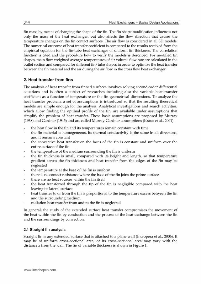
Straight fin is any extended surface that is attached to a plane wall (Incropera et al., 2006). It may be of uniform cross–sectional area, or its cross–sectional area may vary with the distance x from the wall. The fin of variable thickness is shown in Figure 1.
www.intechopen.com
Fin-Tube Heat Exchanger Optimization
345
Fig. 1. Straight fin of variable cross section.
Both the conduction through the fin cross section and the convection over the fin surface area take place in and around the fin. When the fin temperature is lower than the base (primary surface) temperature 0T , the heat is transferred from the fin to the surroundings
(Shah & Sekulic, 2003).
The fin height is l , width is w , variable thickness ( )x . Its perimeter for surface convection
depends on coordinate x and is ( ) 2[ ( )]P x w x . Its cross-sectional area for heat
conduction at any cross section is ( ) ( )A x x w , where – fin thickness as a function of
x , w - fin width.
The temperature distribution can be calculated taking into consideration an energy balance
on a typical element between x and x d x , shown in Figure 2.
Fig. 2. Energy balance on a typical element.
)x(
xd
xdx x
CONV
.
Qd
x
.
Q xdx
.
Q
x
l
w
)x(
w)x()x(A 0T
)]x(w[2)x(P
CONVQ
0Q
www.intechopen.com
Heat Exchangers – Basics Design Applications
346
The energy balance:
. . .
0x x d x CONVQ Q d Q (1)
where
.
,f k xx
dTQ k A
d x (2)
.
, ,( ( ) )f k x k xx d x
dT d dTQ k A A d x
d x d x d x (3)
.
( ) ( )f S SCONVdQ h A T T h P d x T T (4)
Where
fk – fin thermal conductivity
h – heat transfer coefficient
ST – surrounding temperature
fA – fin surface area
,k xA – cross-sectional area as a function of k and x
P - perimeter (function of x )
Then
,( ) ( )f k x S
d dTk A d x h P d x T T
d x d x (5)
and
2
,2
, ,
1( ) 0k x
Sk x f k x
d Ad T dT h PT T
A d x d x k Ad x (6)
or
2
, 22
(ln )( ) 0k x
S
d Ad T dTm T T
d x d xd x (7)
where
2
,f k x
h Pm
k A (8)
Both P and ,k xA are the function of x or a variable cross section.
To simplify the equation, the new dependent variable is introduced:
www.intechopen.com
Fin-Tube Heat Exchanger Optimization
347
( ) ( ) Sx T x T (9)
where
– temperature difference between a point on a fin surface and the surroundings, 0C
Because the ambient (surrounding) temperature is assumed to be constant, then:
d dT
d x d x
(10)
and
2
, 22
(ln )0k xd Ad d
md x d xd x
(11)
This second order, linear, homogeneous ordinary differential equation with nonconstant coefficients is valid for any thin fins of variable cross section. Once the boundary conditions and the fin geometry are specified, its solution will provide the temperature distribution and subsequently, the heat transfer rate through the fin (Shah & Sekulic, 2003)
2.2 Circular fin analysis
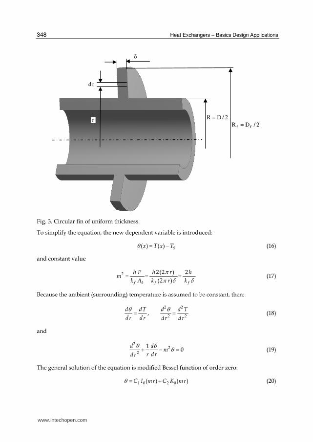
The fin of uniform thickness of circular fin that can be applied on the outside of a tube is shown in Figure 3. Such fins have extensive application in liquid-gas heat exchangers (Mills, 1995).
The energy balance on a typical element of circular fin between r and r dr can be
written as:
( 2 ) ( 2 ) 2 (2 ) ( ) 0r r d r Sq r q r h r dr T T (12)
where
f
dTq k
dr (13)
fk – fin thermal conductivity
– fin thickness
ST – surrounding temperature
then:
( ) ( ) 02
S
dr q hr T T
dr
(14)
2
( ) ( ) 0Sf
dT hrdr T T
dr dr k (15)
www.intechopen.com
Heat Exchangers – Basics Design Applications
348
Fig. 3. Circular fin of uniform thickness.
To simplify the equation, the new dependent variable is introduced:
( ) ( ) Sx T x T (16)
and constant value
2 2(2 ) 2
(2 )f k f f
h P h r hm
k A k r k
(17)
Because the ambient (surrounding) temperature is assumed to be constant, then:
2 2
2 2,
d dT d d T
dr dr dr dr
(18)
and
2
22
10
d dm
r drdr
(19)
The general solution of the equation is modified Bessel function of order zero:
1 0 2 0( ) ( )C I mr C K mr (20)
rd
r2/DR ff
2/DR
www.intechopen.com
Fin-Tube Heat Exchanger Optimization
349
where 0I and 0K are modified, zero-order Bessel functions of the first and second kind
respectively.
Assuming the constant and known base temperature and zero heat flow through the tip of the fin:
0 0 0 Sr R T T T T (21)
0 0f ff r R r R
dT dr R
dr dr
(22)
where
fR – radial coordinate of fin tip ( / 2f fR D )
R – radial coordinate of fin base (external tube radius / 2R D )
From the first condition:
0 1 0 2 0( ) ( )C I mR C K mR (23)
From the second condition and according to differentiation rules
1 0 1 1[ ( )] ( )d
C I mr C mI mrdr
(24)
2 0 2 1[ ( )] ( )d
C K mr C mK mrdr
(25)
we obtain:
1 1 2 1 1 1 2 1( ) ( ) ( ) ( ) 0f fr R r R f f
dC mI mr C mK mr C mI mR C mK mR
dr
(26)
1C and 2C can be evaluated to find a temperature distribution:
0 1 0 1
0 0 1 0 1
( ) ( ) ( ) ( )
( ) ( ) ( ) ( )
f f
f f
I mr K mR K mr I mR
I mR K mR K mR I mR
(27)
where
01
[ ( )]( )
( )
d I mrI mr
d mr and 0
1
[ ( )]( )
( )
d K mrK mr
d mr are modified, first order Bessel functions of
the first and second kind.
Heat dissipated by the fin and its efficiency can be expressed as:
.
(2 )f k r R f r R
dT dQ k A k R
dr dr
(28)
www.intechopen.com
Heat Exchangers – Basics Design Applications
350
where is the fin thickness.
Then
.
1 1 1 10
0 1 0 1
( ) ( ) ( ) ( )2
( ) ( ) ( ) ( )
f ff
f f
K mR I mR I mR K mRQ R k m
K mR I mR I mR K mR (29)
and fin efficiency
.
1 1 1 1
2 2 2 20 1 0 10
( ) ( ) ( ) ( )2
( ) ( ) ( ) ( )2 ( ) ( )
f ff
f ff f
K mR I mR I mR K mRRQ
K mR I mR I mR K mRh R R m R R
(30)
This result may be applied for an “active” tip (no zero heat flow through the tip of the fin) if
the tip radius fR is replaced by the corrected radius of the form _2
f COR fR R
(Incropera et al., 2006). The fin tip area can be also neglected, taking into consideration the fact that the heat transfer at the fin tip is small. Some authors propose using simpler expressions for hand calculations (Shah & Sekulic, 2003).
2.3 Circular fin thickness optimization
The simple radial fin with a rectangular profile is sketched in Figure 3. The fin profile and its optimization issue is often the subject of research. Different authors eliminate some of Murray-Gardner assumptions in their investigations that make the problem more complex. The literature includes a large number of publications dealing with convective heat transfer for different surface geometry, fluid flow type, fluid composition, and thermal boundary conditions but without considering the fluid flow motion.
For the ideal case, if the convection is considered in a fin heat exchanger and the surrounding temperature is equal to ST , the temperature difference between any point on
the fin surface and the surrounding temperature can be written as:
( ) ST r T (31)
where:
( )T r is the fin surface temperature that varies from the fin base to the fin tip
The optimized profile of the symmetrical radial fin of least material can be found from the generalized differential equation (Kraus et al., 2001):
2
2
( ) ( )( ) 0
f
f r d f rd d d hf r
r kd r d r d r d r
(32)
assuming that the temperature excess changes linearly:
0 1
f
f
r R
R R
(33)
www.intechopen.com
Fin-Tube Heat Exchanger Optimization
351
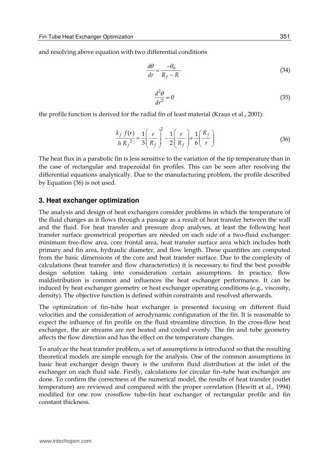
and resolving above equation with two differential conditions
0
f
d
dr R R
(34)
2
20
d
dr
(35)
the profile function is derived for the radial fin of least material (Kraus et al., 2001):
2
2
( ) 1 1 1
3 2 6
f f
f ff
k f r Rr r
R R rh R
(36)
The heat flux in a parabolic fin is less sensitive to the variation of the tip temperature than in
the case of rectangular and trapezoidal fin profiles. This can be seen after resolving the
differential equations analytically. Due to the manufacturing problem, the profile described
by Equation (36) is not used.
3. Heat exchanger optimization
The analysis and design of heat exchangers consider problems in which the temperature of the fluid changes as it flows through a passage as a result of heat transfer between the wall and the fluid. For heat transfer and pressure drop analyses, at least the following heat transfer surface geometrical properties are needed on each side of a two-fluid exchanger: minimum free-flow area, core frontal area, heat transfer surface area which includes both primary and fin area, hydraulic diameter, and flow length. These quantities are computed from the basic dimensions of the core and heat transfer surface. Due to the complexity of calculations (heat transfer and flow characteristics) it is necessary to find the best possible design solution taking into consideration certain assumptions. In practice, flow maldistribution is common and influences the heat exchanger performance. It can be induced by heat exchanger geometry or heat exchanger operating conditions (e.g., viscosity, density). The objective function is defined within constraints and resolved afterwards.
The optimization of fin–tube heat exchanger is presented focusing on different fluid velocities and the consideration of aerodynamic configuration of the fin. It is reasonable to expect the influence of fin profile on the fluid streamline direction. In the cross-flow heat exchanger, the air streams are not heated and cooled evenly. The fin and tube geometry affects the flow direction and has the effect on the temperature changes.
To analyze the heat transfer problem, a set of assumptions is introduced so that the resulting theoretical models are simple enough for the analysis. One of the common assumptions in basic heat exchanger design theory is the uniform fluid distribution at the inlet of the exchanger on each fluid side. Firstly, calculations for circular fin–tube heat exchanger are done. To confirm the correctness of the numerical model, the results of heat transfer (outlet temperature) are reviewed and compared with the proper correlation (Hewitt et al., 1994) modified for one row crossflow tube-fin heat exchanger of rectangular profile and fin constant thickness.
www.intechopen.com
Heat Exchangers – Basics Design Applications
352
3.1 Optimization and objective function
The optimization process should lead to project the heat exchanger that meets the stated criteria (for instance heat transfer required, minimum weight, heat exchanger efficiency or performance, allowable pressure drop etc).
There are different types of the optimization for radial fin heat exchangers. The optimization can consider (Kraus et al., 2001):
- minimum weight for a specified heat flow - fin profile based on a set of specified conditions (for instance the dissipation from the
fin faces and calculation of minimum volume as well as minimum profile area) - placement of individual fins to form channels
One of the important issues that should be defined during the design work is the optimization of the heat efficiency, taking into consideration the cost of material and the whole heat exchanger.
As an example, the objective function is to maximize the heat transfer ratio for elementary heat exchanger mass (or volume for known material density) in fin-tube heat exchanger. It
means that the fin profile is optimized to find the maximum value of function , defined as
the ratio between the heat removed from the tube/fin component to the tube/fin weight:
.
s
Q
m (37)
where
.
Q – heat flow removed from the fluid to the fin and tube
sm – tube and fin mass (solid).
Introducing fc – fluid (air) specific heat capacity, fm
– fluid mass flow rate, INT – fluid
temperature in the inlet section, TT – internal tube surface temperature, s – material
density of solid (tube and fin), sV – volume of tube and fin material, the ratio is equal:
( )f f IN OUT
s s
m c T T
V
(38)
If the values of fc , s do not change during the air flow, then the optimization problem can
be resolved by finding the maximum value of the optimization function, :
. .
( )max
f fIN OUT Fluid
s s
m T T m T
V V (39)
where
Fluid IN OUTT T T - difference in fluid temperature between outlet and inlet section.
www.intechopen.com
Fin-Tube Heat Exchanger Optimization
353
The temperature difference is found numerically and the solid volume is calculated for different fin profile shapes. The air temperature value is also computed numerically in the outlet section and the average air temperature is evaluated.
3.2 Numerical optimization of fin shape
To analyze the exchanger heat transfer problem, a model of heat exchanger is built under some assumptions:
- the heat exchanger operates under steady-state conditions - heat losses to or from the surroundings are negligible - there are no thermal energy sources or sinks in the exchanger walls or fluids, - there is no thermal resistance between tube and fins, - the physical properties of material and fluid do not depend on temperature (specific
heat, density, heat conduction …) - the velocity and temperature of the fluid at the entrance of the heat exchanger are
uniform over the flow cross section. - the fluid flow rate is uniformly distributed through the exchanger - there is no flow leakages in any stream.
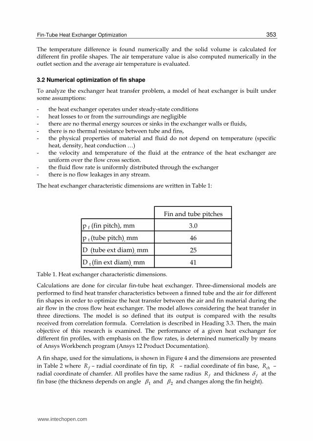
The heat exchanger characteristic dimensions are written in Table 1:
Calculations are done for circular fin-tube heat exchanger. Three-dimensional models are
performed to find heat transfer characteristics between a finned tube and the air for different
fin shapes in order to optimize the heat transfer between the air and fin material during the
air flow in the cross flow heat exchanger. The model allows considering the heat transfer in
three directions. The model is so defined that its output is compared with the results
received from correlation formula. Correlation is described in Heading 3.3. Then, the main
objective of this research is examined. The performance of a given heat exchanger for
different fin profiles, with emphasis on the flow rates, is determined numerically by means
of Ansys Workbench program (Ansys 12 Product Documentation).
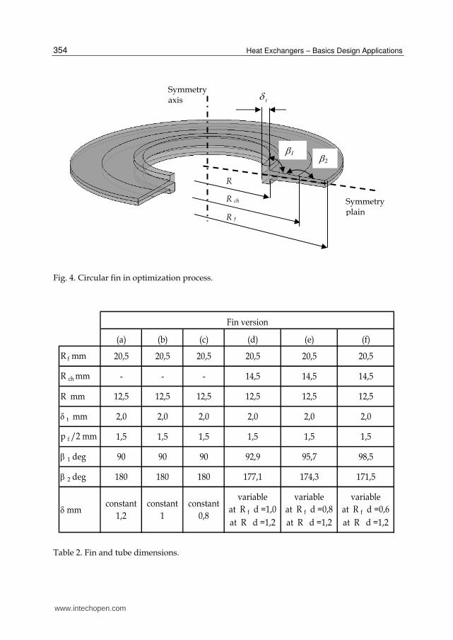
A fin shape, used for the simulations, is shown in Figure 4 and the dimensions are presented
in Table 2 where fR – radial coordinate of fin tip, R – radial coordinate of fin base, chR –
radial coordinate of chamfer. All profiles have the same radius fR and thickness f at the
fin base (the thickness depends on angle 1 and 2 and changes along the fin height).
www.intechopen.com
Heat Exchangers – Basics Design Applications
354
Fig. 4. Circular fin in optimization process.
(a) (b) (c) (d) (e) (f)
R f mm 20,5 20,5 20,5 20,5 20,5 20,5
R ch mm - - - 14,5 14,5 14,5
R mm 12,5 12,5 12,5 12,5 12,5 12,5
t mm 2,0 2,0 2,0 2,0 2,0 2,0
p f /2 mm 1,5 1,5 1,5 1,5 1,5 1,5
1 deg 90 90 90 92,9 95,7 98,5
2 deg 180 180 180 177,1 174,3 171,5
mmconstant
1,2
constant
1
constant
0,8
variable
at R f d =1,0
at R d =1,2
variable
at R f d =0,8
at R d =1,2
variable
at R f d =0,6
at R d =1,2
Fin version
Table 2. Fin and tube dimensions.
R f
R
Symmetry plain
Symmetry axis
1
R ch
2
t
www.intechopen.com
Fin-Tube Heat Exchanger Optimization
355
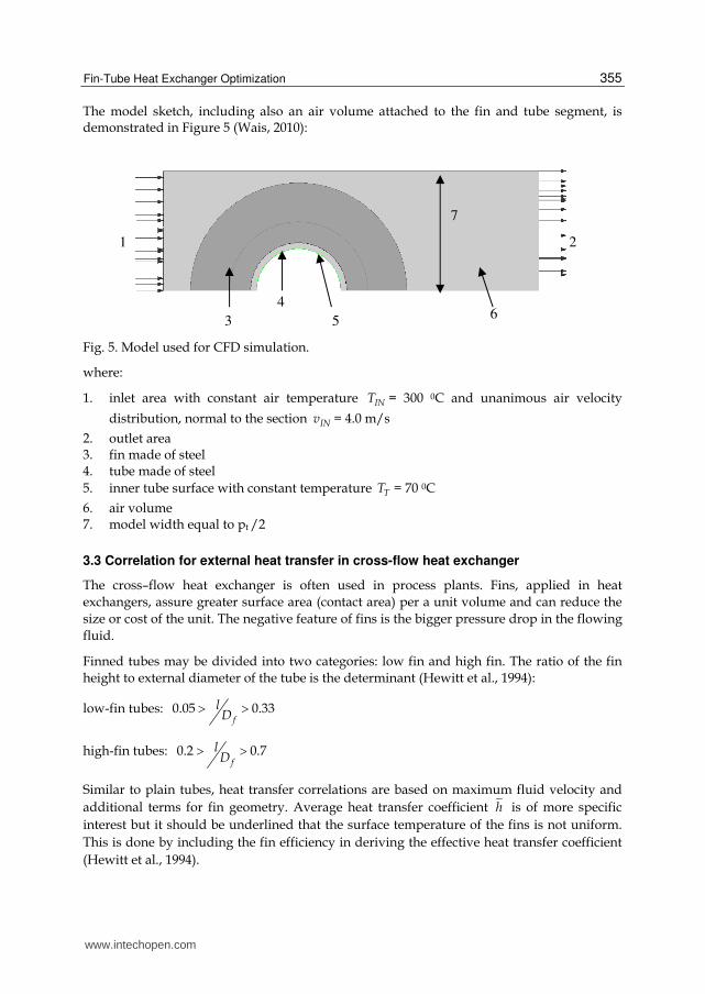
The model sketch, including also an air volume attached to the fin and tube segment, is demonstrated in Figure 5 (Wais, 2010):
Fig. 5. Model used for CFD simulation.
where:
1. inlet area with constant air temperature INT = 300 0C and unanimous air velocity
distribution, normal to the section INv = 4.0 m/s
2. outlet area 3. fin made of steel 4. tube made of steel
5. inner tube surface with constant temperature TT = 70 0C
6. air volume 7. model width equal to pt /2
3.3 Correlation for external heat transfer in cross-flow heat exchanger
The cross–flow heat exchanger is often used in process plants. Fins, applied in heat
exchangers, assure greater surface area (contact area) per a unit volume and can reduce the
size or cost of the unit. The negative feature of fins is the bigger pressure drop in the flowing
fluid.
Finned tubes may be divided into two categories: low fin and high fin. The ratio of the fin
height to external diameter of the tube is the determinant (Hewitt et al., 1994):
low-fin tubes: 0.05 0.33f
lD
high-fin tubes: 0.2 0.7f
lD
Similar to plain tubes, heat transfer correlations are based on maximum fluid velocity and
additional terms for fin geometry. Average heat transfer coefficient h is of more specific
interest but it should be underlined that the surface temperature of the fins is not uniform.
This is done by including the fin efficiency in deriving the effective heat transfer coefficient
(Hewitt et al., 1994).
1 2
5
7
3
46
www.intechopen.com
Heat Exchangers – Basics Design Applications
356
Therefore:
maxReD
v D (40)
.
maxmin
fmv
S (41)
f
hDNu
k (42)
where
D – external tube diameter,
maxv – maximum fluid velocity (in minimum flow area),
– fluid density,
– fluid dynamic viscosity,
minS – minimum flow area,
fk – fin thermal conductivity,
h – average heat transfer coefficient
Typical fin-tube geometry, with surface area equation and minimum cross-sectional area, are presented in Figure 6.
Surface area of one sector (consists of fin and tube) are defined as:
Surface area of fins: 2 21( )
2f f fA D D D
Surface area of tube between fins: tA D s
Total surface area: 2 21( )
2f fA D D D D s
Total tube surface (with fin removed): ( )TA D s
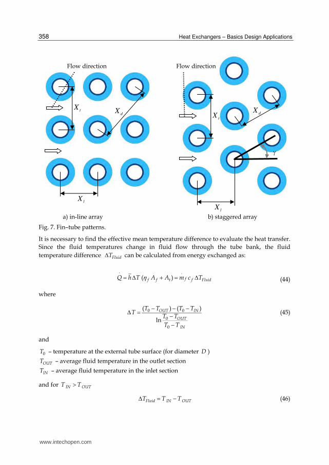
Characteristic fin–tube heat exchanger configurations are shown in Figure 7.
Average heat transfer coefficient h is of more specific interest for the whole process, which
is correlated with the maximum velocity between tubes maxv .
Total heat transfer can be calculated taking into consideration fin efficiency:
( ) 'f f tQ h T A A h T A (43)
www.intechopen.com
Fin-Tube Heat Exchanger Optimization
357
where
f – fin efficiency
h - average heat transfer coefficient
'h – effective heat transfer coefficient
T – effective mean temperature difference,
A – total external area of the tubes and fins
Fig. 6. Fin–tube geometry.
l
s
fp
D
fD
t
One sector
tp
www.intechopen.com
Heat Exchangers – Basics Design Applications
358
a) in-line array b) staggered array
Fig. 7. Fin–tube patterns.
It is necessary to find the effective mean temperature difference to evaluate the heat transfer.
Since the fluid temperatures change in fluid flow through the tube bank, the fluid
temperature difference FluidT can be calculated from energy exchanged as:
.
( ) ff f t f FluidQ h T A A m c T (44)
where
0 0
0
0
( ) ( )
ln
OUT IN
OUT
IN
T T T TT
T T
T T
(45)
and
0T – temperature at the external tube surface (for diameter D )
OUTT – average fluid temperature in the outlet section
INT – average fluid temperature in the inlet section
and for IN OUTT T
Fluid IN OUTT T T (46)
lX
dXt
X
lX
dX
tX
Flow direction Flow direction
www.intechopen.com
Fin-Tube Heat Exchanger Optimization
359
After transformation
.
( )f f tFluid
f f
h A AT T
m c
(47)
.
( )f f tOUT IN
f f
h A AT T T
m c
(48)
finally
.
0
.
( )1 exp
( )( )
f f t
f f
INf f t
f f
h A A
m cT T T
h A A
m c
(49)
The value of heat transfer depends on local fluid velocity, fluid properties and details of the
tube bank geometry. Correlations that allow calculating average heat transfer coefficient, h ,
are derived from experimental data and take into account geometrical features.
Having calculated average heat transfer coefficient, h , effective mean temperature
difference, T , and fin efficiency, f , the rate of heat transfer equals:
( )f f tQ h T A A (50)
3.3.1 Correlation for low fin tube
The average Nusselt number for low fin tube can be calculated from below correlation
(Hewitt et al., 1994):
0.06 0.110.360.7 0.36
1 2 30.183 Re Prt
f f
Xs lNu F F F
l D D
(51)
where
1F – factor for fluid property variation (significant only at high temperatures),
0.26
_1
Pr
PrFluid Ave
S
F ,
_PrFluid Ave – Prandtl number of fluid for bulk temperature _Fluid AveT
PrS – Prandtl number of fluid for mean tube and fin surface temperature, ST
www.intechopen.com
Heat Exchangers – Basics Design Applications
360
2F – factor for number of fin – tube raws
for number of raws > 10: 2F = 1.000
for number of raws = 8: 2F = 0.985
for number of raws = 6: 2F = 0.955
for number of raws = 4: 2F = 0.900
3F – factor for staggered arrangement ( = 30 , 45 ,60o o o , see Fig. 5. for definition) 3F =1
3F – factor for in-line arrangement 3 o
for plain tube (in-line)
for plain tube staggered array ( 30 )
NuF
Nu
Above recommended correlation is applicable for Reynolds number 3 510 Re 8 10 ,
0.19 0.66s
l , 1.1 4.92t
f
X
D , 0.058 0.201
f
l
D (Hewitt et al., 1994)
3.3.2 Correlation for high fin tube
Recommended correlation to calculate the average Nusselt number for staggered tube banks by Engineering Science Data (Hewitt et al., 1994) and Reynolds number range
3 42 10 Re 4 10 , 0.13 0.57s
l , 1.15 1.72t
l
X
X :
0.0910.2971 30.658
1 20.242 Re Prt
l
XsNu F F
l X
(52)
where
1F – factor for fluid property variation (significant only at high temperatures)
2F – factor for number of fin – tube raws
1.0 for four or more raws, 0.92 for three raws 0.84 for two raws 0.76 for one raw
For high fin-tube and in–line array the correlation that can be applied for Reynolds number
3 55 10 Re 10 , and 5 12T
A
A :
0.375
0.625 0.3330.30 Re PrT
ANu
A
(53)
where
TA – total tube surface area of one sector, ( )TA D s
A – total surface area of one sector, 2 21( )
2f fA D D D D s
www.intechopen.com
Fin-Tube Heat Exchanger Optimization
361
Calculating the average Nusselt number, the fin efficiency value f can be achieved from
(McQuiston & Tree, 1972):
tanh( 2 /( ) )
2 /( )
f
f
f
h k
h k
(54)
where
1 1 0.35 ln2
f fD DD
D D (55)
4. Results
The heat exchange optimization function is defined as the amount of dissipated heat to the
heat exchanger weight for a one raw heat exchanger (optimization parameter is the profile
shape). The shape of the fin is modified to calculate heat transfer, reduce the total mass that
refers to the cost of the whole heat exchanger. The performance of the heat transfer process
in a given heat exchanger is determined for different fin profiles, considering the fluid flow.
Fin geometry affects the heat transfer phenomenon between the plate itself and the air.
Changing the fin profile, the fluid streamline can be modified in a way that it affects the
temperature changes on the fin surface and heat convection conditions.
Numerical analyses are carried out to examine a modified finned tube heat exchanger. The
tube material is kept fixed as well as the heat exchanger fin and tube pitches (spacing). No
changes are done to the inlet and outlet temperature and pressure values. The shape of the
fin and tube is modified to calculate heat transfer for different conditions, reduce the total
mass that refers to the cost of the whole heat exchanger. The temperature difference is found
numerically and the solid volume is calculated for different fin profile shapes.
To confirm the correctness of the numerical model, the results of the heat transfer are
reviewed and compared with those received from the correlation recommended by
Engineering Sciences Data Unit, Equation (52), modified for one row crossflow tube-fin heat
exchanger of rectangular profile and fin constant thickness - fin profile (a), (b) and (c).
Results are presented in Table 3.
Comparison, shown in Table 3, should be used only as a reference. Correlations for the heat
transfer of air flow are expressed for at least 4 tube raws. Then factors are introduced to
recalculate Nu number for one raw heat exchanger. The standard deviation of correlation
for external flow is about 25% for laminar flow and 15% for turbulent flow (Hewitt et al.,
1994). Presented correlation is used to check the model accuracy in relation to fin shape
modifications.
After model verification, the fin of variable thickness is considered and the optimized
function is calculated. The fin thickness near the tube is set up to be constant and equal
to model (a) thickness (for manufacturing and operating reason) and the mass flow in outlet
section .
fm does not change in different models.
www.intechopen.com
Heat Exchangers – Basics Design Applications
362
(a) (b) (c)
T_model [0C] 45.5 44.7 43.9
T_correl [0C] 45.7 43.3 41.4
-0.4% 3.2% 6.0%
Fin version
T_correlΔT_correlΔT_modelΔ
Table 3. Results from numerical calculation and correlation.
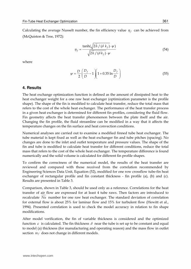
The values of the optimization function are found and presented in Table 4 where:
( )IN OUT
s
T T
V from Equation (39) for constant
.
fm , model ( ) m odel ( )
m odel ( )
i ai
a
T TT
T
,
model ( ) model ( )
model ( )
i ai
a
:
(d) (e) (f)
T_model [0C] 42,8 40,9 37,8
T_model (a) [0C] 45,5 45,5 45,5
-5,9% -10,1% -16,9%
5,2% 13,6% 20,9%
Fin version
iTi
Table 4. Results from numerical calculation for profile modification.
The results illustrate how the fin dimensions and configuration influence the heat transfer.
The function i is higher for models with profile modification.
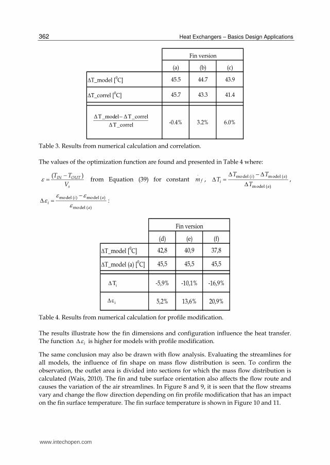
The same conclusion may also be drawn with flow analysis. Evaluating the streamlines for
all models, the influence of fin shape on mass flow distribution is seen. To confirm the
observation, the outlet area is divided into sections for which the mass flow distribution is
calculated (Wais, 2010). The fin and tube surface orientation also affects the flow route and
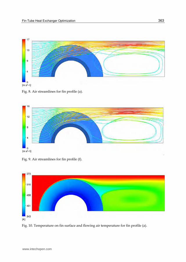
causes the variation of the air streamlines. In Figure 8 and 9, it is seen that the flow streams
vary and change the flow direction depending on fin profile modification that has an impact
on the fin surface temperature. The fin surface temperature is shown in Figure 10 and 11.
www.intechopen.com
Fin-Tube Heat Exchanger Optimization
363
Fig. 8. Air streamlines for fin profile (a).
Fig. 9. Air streamlines for fin profile (f).
Fig. 10. Temperature on fin surface and flowing air temperature for fin profile (a).
www.intechopen.com
Heat Exchangers – Basics Design Applications
364
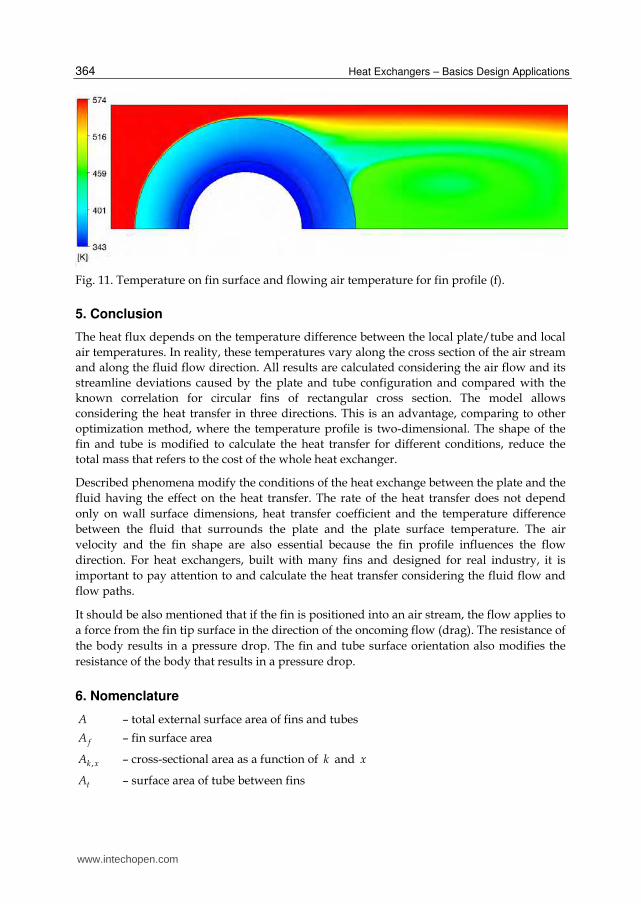
Fig. 11. Temperature on fin surface and flowing air temperature for fin profile (f).
5. Conclusion
The heat flux depends on the temperature difference between the local plate/tube and local
air temperatures. In reality, these temperatures vary along the cross section of the air stream
and along the fluid flow direction. All results are calculated considering the air flow and its
streamline deviations caused by the plate and tube configuration and compared with the
known correlation for circular fins of rectangular cross section. The model allows
considering the heat transfer in three directions. This is an advantage, comparing to other
optimization method, where the temperature profile is two-dimensional. The shape of the
fin and tube is modified to calculate the heat transfer for different conditions, reduce the
total mass that refers to the cost of the whole heat exchanger.
Described phenomena modify the conditions of the heat exchange between the plate and the
fluid having the effect on the heat transfer. The rate of the heat transfer does not depend
only on wall surface dimensions, heat transfer coefficient and the temperature difference
between the fluid that surrounds the plate and the plate surface temperature. The air
velocity and the fin shape are also essential because the fin profile influences the flow
direction. For heat exchangers, built with many fins and designed for real industry, it is
important to pay attention to and calculate the heat transfer considering the fluid flow and
flow paths.
It should be also mentioned that if the fin is positioned into an air stream, the flow applies to
a force from the fin tip surface in the direction of the oncoming flow (drag). The resistance of
the body results in a pressure drop. The fin and tube surface orientation also modifies the
resistance of the body that results in a pressure drop.
6. Nomenclature
A – total external surface area of fins and tubes
fA – fin surface area
,k xA – cross-sectional area as a function of k and x
tA – surface area of tube between fins
www.intechopen.com
Fin-Tube Heat Exchanger Optimization
365
TA – total tube surface (with fin removed)
fc – fluid (air) specific heat capacity
D – external tube diameter (also diameter of fin base),
fD – diameter of fin tip
h – average heat transfer coefficient
'h – effective heat transfer coefficient
0I – modified, zero-order Bessel function of the first kind
1I – modified, first-order Bessel function of the first kind
0K – modified, zero-order Bessel function of the second kind
1K – modified, first-order Bessel function of the second kind
fk – fin thermal conductivity,
l – fin height
fm
– fluid mass flow rate
sm – tube and fin mass (solid).
Nu – average Nusselt number
P - perimeter (function of x)
fp – fin pitch
tp – tube pitch
.
Q – heat flow removed from the fluid to the fin and tube
R – radial coordinate of fin base (external tube radius / 2R D )
chR – radial coordinate of chamfer
fR – radial coordinate of fin tip ( / 2f fR D )
Re – Reynolds number
minS – minimum flow area
s – spacing between adjacent fins
0T – temperature at the external tube surface (for diameter D )
INT – fluid temperature in the inlet section
OUTT – average fluid temperature in the outlet section
ST – surrounding temperature
TT – inner tube surface temperature
sV – volume of tube and fin material
INv – air velocity in the inlet section
maxv – maximum fluid velocity (in minimum flow area)
w – fin width
dX – diagonal tube pitch ( 2 2t tX X )
lX – longitudinal (parallel to the flow) tube pitch
www.intechopen.com
Heat Exchangers – Basics Design Applications
366
tX – transverse tube pitch (perpendicular to the flow) tube pitch
Greek symbols
T – effective mean temperature difference
_T correl –difference in air temperature between inlet and outlet section calculated from
correlation
_ modelT –difference in air temperature between inlet and outlet section received from
numerical computation
Fluid IN OUTT T T - difference in fluid temperature between outlet and inlet section
– fin thickness
t – tube thickness
– optimization function – fluid dynamic viscosity,
f – fin efficiency
– temperature difference between a point on a fin surface and the surroundings
– ratio between the heat removed from the tube/fin component to the tube/fin
weight – fluid density
s – material density of solid (tube and fin)
7. References
Ansys 12 Product Documentation, Available from ANSYS Customer Portal, https://www1.ansys.com/customer/default.asp
Hewitt G. H., Shires G. L., Bott T. R. (1994). Process Heat Transfer, CRC Press Inc., ISBN 0–8493–9918–1, USA
Incropera F. P., Dewitt D. P., Bergman T. L., Lavine A. S. (2006), Fundamentals of Heat and Mass Transfer, John Wiley & Sons, ISBN 978–0–471–45728–2, USA
Kraus A., Aziz A., Welty J. (2001) Extended surface heat transfer, A Willey-Interscience Publication, ISBN 0–471–39550–1, USA
Mills A. F. (1995), Heat and Mass Transfer, Richard D. Irwin Inc., ISBN 0–256–11443–9, USA McQuiston F. C., Tree D. R. (1972), Optimum space envelopes of the finned tube heat transfer
surface, ASHRAE Transactions, Vol. 78, Part 2, pp. 144-152, ISSN: 0001–2505 Shah R. K., Sekulic D. P. (2003), Fundamentals of Heat Exchanger Design, John Wiley & Sons,
ISBN 0–471–32171–0, USA Wais P. (2010), Fluid flow consideration in fin-tube heat exchanger optimization, Archives of
InTech ChinaUnit 405, Office Block, Hotel Equatorial Shanghai No.65, Yan An Road (West), Shanghai, 200040, China
Phone: +86-21-62489820 Fax: +86-21-62489821
Selecting and bringing together matter provided by specialists, this project offers comprehensive informationon particular cases of heat exchangers. The selection was guided by actual and future demands of appliedresearch and industry, mainly focusing on the efficient use and conversion energy in changing environment.Beside the questions of thermodynamic basics, the book addresses several important issues, such asconceptions, design, operations, fouling and cleaning of heat exchangers. It includes also storage of thermalenergy and geothermal energy use, directly or by application of heat pumps. The contributions arethematically grouped in sections and the content of each section is introduced by summarising the mainobjectives of the encompassed chapters. The book is not necessarily intended to be an elementary source ofthe knowledge in the area it covers, but rather a mentor while pursuing detailed solutions of specific technicalproblems which face engineers and technicians engaged in research and development in the fields of heattransfer and heat exchangers.
How to referenceIn order to correctly reference this scholarly work, feel free to copy and paste the following: