FINAL CONTROL TECHNOLOGY ASSESSMENT FOR COAL GASIFICATION AND LIQUEFACTION PROCESSES Coal Gasification Facility Pennsylvania Report for the Site Visit of May 1981 Contract No. 210-78-0084 Apri 1 1982 Submi tted to: Phillip A. Froehlich, Project Officer National Institute for Occupational Safety and Health Division of Physical Sciences and Engineering Robert A. Taft Laboratories 4676 Columbia Parkway Cincinnati, Ohio 45226 Submitted by: Donato R. Manager Engineering Department Dynamac Corporation Enviro Control Division Dynamac Building 11140 Rockville Pike Rockville, Maryland 20852
Transcript
FINAL
CONTROL TECHNOLOGY ASSESSMENT FOR
COAL GASIFICATION AND LIQUEFACTION PROCESSES
Coal Gasification FacilityPennsylvania
Report for the Site Visit of May 1981
Contract No. 210-78-0084
Apri 1 1982
Submi tted to:
Phillip A. Froehlich, Project Officer National Institute for Occupational
Safety and Health Division of Physical Sciences and Engineering
Robert A. Taft Laboratories 4676 Columbia Parkway
Cincinnati, Ohio 45226
Submitted by:
Donato R. Te1~sca, Manager Engineering Department
Dynamac Corporation Enviro Control Division
Dynamac Building11140 Rockville Pike
Rockville, Maryland 20852
FOREWORD
On August 18, 1980 and May 7, 1981 visits were made to the gasification
facility at the Caterpillar Tractor Company in York, Pennsylvania. The purpose of these visits was to study the technology used to control occupa
tional exposure to chemical and physical hazards at the gasification facil ity. On August 18, 1980 the study was conducted in conjunction with an
ind~strial hygiene characterization study of the facility. The following
people were in attendance at the initial meeting of the August 1980 visit:
For Caterpillar Tractor Company
Mr. K. Thompson, Corporate Manger, Industrial Hygiene Mr. C. Williams, Industrial Hygienist, Corporate Office
Peoria, Illinois
Mr. R. Julian, Manager, Plant Services, York, Pennsylvania Mr. W. Glass, Safety Supervisor, York, Pennsylvania Dr. G. Sprague, M.D., Medical Department, York, Pennsylvania Mr. W. Norton, Plant Engineer, York, Pennsylvania Mr. J. Misiolek, Supervising Engineer, York, Pennsylvania
Mr. J. King, Staff Engineer, York, Pennsylvania
For Enviro Control, Inc.
Mr. D. Telesca, Program Manager
Mr. J. Scopel, Chemical Engineer
Mr. R. Tanita, Industrial Hygienist
i i
I. INTRODUCTION
A. Background
The objective of the IlControl Technology Assessment for Coal Gasification
and Liquefaction Processes" program is to study the control technologies that are currently used to prevent occupational exposure to hazardous agents
in coal conversion plants. This information is gathered during site visits to engineering firms, gasification facilities, and liquefaction facilities.
Of particular importance is the industrial use of low-Btu coal gasification
processes because of their potential for replacing lnore expensive and scarce
fuels such as natural gas and oil. The low-Btu gasifier used by the Penn
sylvania manufacturing plant is a Lwo-stage gasifier. This report discusses
the control technologies and work practices in use at the coal gasification
facility in Pennsylvania during the site visits of August 18, 1980 and May 7, 1981. This facility is one of the first privately fihanced low-Btu coal gasification operations in the United States, and represents the first com
mercial operation designed to gasify a high sulfur coal to produce a clean fuel gas.
B. Project History
The gasification project at the Pennsylvania manufacturing plant represents
one of the first privately financed low-Btu gaSification operations in the
United States. The objective of the project is to provide a supply of fuel
gas to the plant carburizer furnaces at a price linked to the supply and cost of coal rather than natural gas. Gi lbert Associates in Reading, Penn
sylvania, designed the 150 ton-per-day facility. The impetus'to proceed with Ule project was the natural gas curtailments in 1973 and continuing
during following years which forced production cutbacks at the manufacturing plant. Two gasifiers were purchased from Black, Sivalls, &Bryson (8S&8),
an engineering firm that designed and sold the Wellman-Incandescent gasifier under 1 icense from We llman of Eng 1 and. Each gas ifi er consumes 67.5 tons of
coa 1 per day to produce approximately 14 mi 11 ion cubi c feet of lOYJ-8tu gas
per day. The gas is produced for onsite use in the carburizer furnaces of
the manufacturing plant.
- 1
A six week test run of the facility in the fall of 1979 pointed out numerous problems with the system, including minor probl~ns with the coal preparation
screens, improper coal bed distribution, and a few gas leaks. These pro
blems were corrected and the unit was restarted during Apri 1 1980. In sub
sequent test runs in May and June 1980, critical temperature rises in the carburizer furnaces using the coal derived gas were identical to those when
using natural gas.
The gasifiers are designed for a specific bituminous coal to produce gas,
but startup and shutdown are accomplished using low-sulfur anthracite. The
reas9n for this is that during startup and shutdown the gas produced must be
flared. Gas produced from anthracite is sufficiently free of sulfur and
other impurities to permit flaring without cleanup. Bituminous coal pro
duces a raw gas containing tars and sulfur compounds which must be removed
before use or flaring.
NIOSH Industrial Hygiene Characterization Programs were conducted by Enviro
Control, Inc. at the gasification facility during both anthracite and
bituminous coal gasification. Description and results of the programs are
presented in Section VI of this report. Appendix A presents the sampling
and analytical protocols used in obtaining the data. Results from these
surveys aided in identifying th~ hazards present at the gasification
facility.
During the site survey in August 1980, one ga~ifier was operated on anthra
cite coal to enable a NIOSH sampling program to be conducted. The gas was
flared as described in Section II-D. A similar program was conducted during
the May 1981 visit with the gasifier operating as designed on Ohio bitu
minous coal.
C. Bituminous Coal
1. Process Description
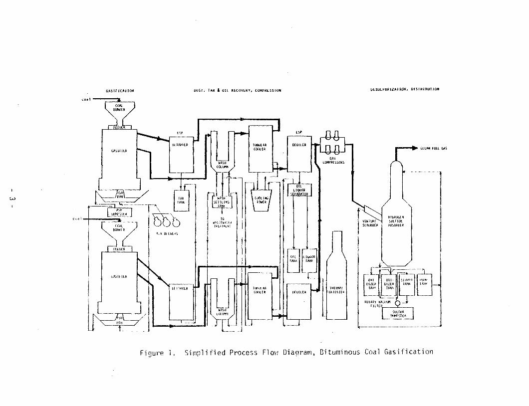
A simplified process flow diagram of the gasification facility is shown in
Figure 1. The major process operations include Coal Storage ana Handling,
GaSification, Ash Removal. Product Gas Cleaning/By-Product Recovery, and
- 2
UESUlFURIZAllOlf, DIS rHIBUIIONGASIFICATlOIf OUST, TAR & OTl RECOVERV, COMPRESSION
(0. J I.
..--..... 'lEAH run UAS
w
co,
Oil 1111~~'lI! IAN, TANr
liTHE kflAtl. ID .oW"
0 --""
10 1IJ.',.i[WAi(ii Ikl},lMlN1
JAR rAlii.
'GDb AIR 810W(rfS
GAS C(I1PR£;.SOkS
A8~OR8ER
Figure 1. Simplified Process Flow Dia~ram, Bituminous Coal Gasification
Desulfurization. Each gasifier train includes dust, tar, and oil recovery equipment. Common facilities are used for coal and ash handling, by-product
storage, desu1furization, and waste treatment.
Coal reclaimed from storage, or delivered by truck is dumped through a grate
outside the gasification facility building into an underground bin. A
vibrating feeder transfers the coal to a belt conveyor which discharges into a bucket elevator. The bucket elevator feeds a vibrating screen which in
turn feeds a screw conveyor. The screw conveyor transfers the coal ~o a storage bin on top of the gasifier. A rotary valve feeds the coal through a
knif~ valve into the top of the gasifier. Off gas from the feeding opera
tion is vented through a baghouse to the atmosphere.
In the gasifier, coal flows counterLurrently to air and steam introduced
through a grate at the bottom of the gasifier. In moving from the top to
the bottom of the gasifier, the coal passes through three reaction zones; . devolatilization, gasification, and combustion. Ash from the combustion
zone exits the bottom of the gasifier to a water-filled ash pan and is conveyed to an ash dumpster for disposal. The operating temperature of the
gasifier ranges from 1800-2100 F (982-1149 C) in the combustion zone to
200-300 F (93-149 C) at the top of the gasifier. The gasifier operating pressure is approximately 20 inches of water.
Two gas streams are removed as product: a top gas which exits at 200-300 F
(93-149 C), and a bottom gas which exits at 800-1000 F (427-538 C). The top gas is sent through an electrostatic precipitator ("detarrer") for tar
removal. The tar is collected in a "day tankll before being pumped to the tar storage tank. The bottom gas is scrubbed in a wash water column for
dust removal. The bottom gas and top gas streams are combined and cooled in the tubular cooler. The mixed product gas flows through a second electro
static precipitator (the "deoiler") to remove oil and phenolic liquor. The oil is separated from the liquor in a settling tank, and is pumped to stor
age. The liquor is first pumped to a liquor storage tank, and then to the thermal oxidizer.
- 4
The mixed product gas is compressed and fed to a Stretford desulfurfzation
unit. Elemental sulfur is collected as a salable by-product. The clean,
low-Btu gas is piped out of the gas plant to the carburizer furnaces in the
manufacturing plant.
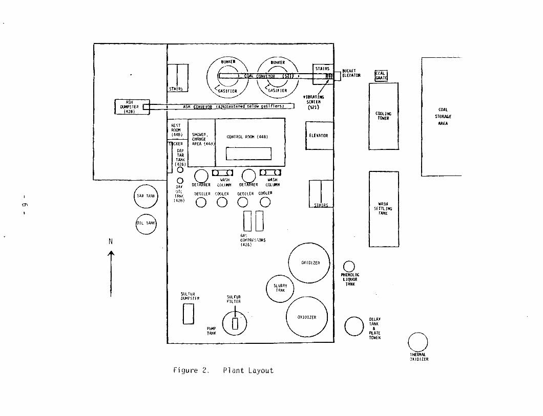
2. Physical Description of Facility
The gasification facility is enclosed in a multi-level steel structure.
Figure 2 is a plot plan showing the location of the major equipment.
Figure 3 is an elevation drawing of the plant showing the location of major
equipment by building level. The coal handling equipment, gasifiers, and
the tar, dust, and oil removal a~d recovery units are located on the upper levels. The Stretford oxidizer slurry tank and pump tanks, the gas com
pressors, and the ash handling e~uipment are located on the lower levels.
The delay tank and plate tower, wash settling tank, cooling tower, thermal
oxidizer, coal storage piles, and the main tar and oil storage tanks are
located outside the structure.
3. Potential Hazards
Many of the process streams associated with this gasification operation contain potentially hazardous chemical and physical agents. Those agents that
are of concern due to their toxic and/or fla~nable nature dre presented by process area in Table 1. Work practices, including administrative controls,
personal protective equipment, personal hygi~ne, and workplace monitoring supplement the engineering controls used to control exposure to these agents.
Low-sulfur anthracite coal, when gasified during st~rtup and shutdown, pro
duces a gas that is essentially free of sulfur, tars, and oils. The gas, after paSSing through a cyclone/condensor to remove particulates, is flared.
During the August 1980 site survey one gasifier was operated using anthracite to permit NIOSH to conduct a sampling survey of an anthracite gasifica
tion operation. When using anthracite in the gasifiers the product gas
cleaning, by-product recovery, and desulfurization units are bypassed.
Instead, all of the gas is taken from the top gas exit, passed through a
cyclone to remove dust (coal fines, carbon, and ash), and flared. The
pro~ess operations required for anthracite gasification are coal storage and
handling, gasification, ash removal, particulate removal, and flaring. The flow diagram for anthracite gasification is shown in Figure 4.
The process for anthracite is the same as for bituminous coal except for the
last two operations. Particulates collected in the cyclone are disposed of
with the tar, and the flared gas dissipates in the atmosphere as carbon dioxide and water.
2. Physical Description of Facility
The plant layout is the same as when bituminous coal is gasified with the
exception that only the coal.handling, gasifying, and ash-handling equip
ment, shown in Figures 1 and 2, are used. The cyclone and flare, which are
only used with anthracite coal, are not shown in Figures 1 and 2.
3. Potential Hazards
As with bituminous coal, there are potentially hazardous chemical and physical agents associated with anthracite gasification. However, due to the low
volatile matter and sulfur content of anthracite, tars and oils (and thus PNAs), and sulfur compounds will essentially be absent. Table 2 lists, by
process area, agents of concern.
- 9
GASIFICATION OUST RECOVERY
COil --;:=:::7t.._-,
CYCLiJN[ GASifIER
FLARE
AIR aUN(05
co. J I--;:~=L.._-,
Figure 4. Simplified Process Flow Diagram Anthracite Coal Gasification
- 10
TABLE 2
Potential Hazards By Process Area Gasification Facility, Pennsylvania
(Anthracite Coal)
Process Area Potential Hazard
Coal Storage and ~andling Respirable Coal Dust Noise Fire Carbon Monoxide
A two part discussion of each process area of the gasification facility is
presented. The first part is a process description. The second part is a discussion of potentially hazardous chemical and physical agents and asso
ciated engineering controls. The term "engineering controls" includes the
use, modification and/or substitution of hardware, chemical feedstocks,
oper9ting conditions, process design, and instrumentation/process controls
that result in reduction or elimination of occupational exposures to poten
tially hazardous agents.
The primary form of engineering control is a closed-system operation from
the time coal enters the system through the outside grate, to the actual use of the clean low-Btu product gas. Only poking operations for fire-bed aepth
determinations and periodic maintenance require breaking into the system.
Other engineering measures include dilution ventildtion and explosion-proof electrical equipment throughout the gas plant.
The dilution ventilation system consists of ten exhaust fans and nine intake
vents. The location of the exhaust fans is shown in Figure 5. The intake vents are located at various levels. The vents are equipped with heaters,
but the system does not provide for cooling of makeup air. The control room is vent 11 ated by a separate system \'Ih1 ch provi des heat i ng alld
air-conditioning. The rectifier and motor control rooms are under positive pressure from outside air. To prevent gas accumulation within the facility,
the dilution ventilation system is designed to provide six air changes per hour within the structure with the doors and windows closea. However,
during the summer months, doors at the ground level are kept open because of the absence of air-conditioning, and this results in an increase of air flow
through the building.
- 12
Door " 426 level"
:.Iall fan
Stairwell
(521 floor' level) '\ exhausts / above ash dumps ter 1-----' unit
Doer '\. 426 level '\
GAilf llR flAY
x Roof (dns x "all fans <:,xhausting above roof of this section (521 tloor neignt)
CO'iTROL ROOM
OUST, TAR. Oil RECOVERY BAY
X Koof tans X
x
Door '\ 426 level'\.
Roof (ans
ST;\EFORS SAY
x
5ta i r well
Fan 455 level
- - -
ELEVATOR
v f\
r--r---1 426
-t> 425
Door ;evel
level
Figure 5.
Exhaust Fan and Door Locations Coal Gasification Facility, Pennsylvania
- 13
B. Coal Storage and Handling
1. Process Description
Coal storage and handling includes all operations from coal receiving to
coal bunker storage just prior to the gasifier feeding system. Coal is
brought to the gasification faci 1 ity storage yards by truck. A front-end
loader moves the coal to coal storage piles where it is stacked eight to
nine feet high.
When_required, the loader dumps coal into a grate located outside of the
gasifier building. The coal drops through the grate to an underground hopper
that feeds a vibrating feeder. Coal from the feeder is conveyed to a bucket
elevator. The bucket elevator carr ies the coal to the 521 level of the gas plant (see Figure 3). The coal is dropped onto a vibrating screen to remove
coal which is less than 1/2 inch by 1/2 inch. This undersized coal drops
through a downleg to a storage bin and is sent to the steam plant.
From the screen, the sized coal drops into an enclosed screw conveyor.
Half-way along the conveyor, coal can be diverted to the coal bunker for the
east gasifier (not in operation at the time of the visit). Coal car~ied to the end of the conveyor is dropped through a dowllleg to the west coal stor
age bunker. The down leg uses a "pants-leg" design to provide a more even distribution of coal in the bunker. A coal bunker dump downleg is provided
on each bunker to evacuate the stored coal to the north side of the building in the event of an emergency such as a fire. A shuttle conveyor just under
the coal bunker enables coal to be used from either bunker to feed botn gasifiers.
2. Control Technology
Undersized coal and fines are removed using the vibrating screen located
between the bucket elevator and the inclined screw conveyor. A separate
storage yard is provided for this reject coal for use in the adjacent steam plant.
- 14
All coal handling equipment above the 410 elevation is now enclosed. All enclosed equipment is under negative pressure. This air is passed through a
baghouse before being exhausted to the atmosphere. The enclosure also reduced the level of noise caused by coal dropping onto the vibrating screen
on the 521 level.
Another problem in this process area is the accumulation of high concentra
tions of carbon monoxide in the coal pit located in the basement of the
facility (410 level). Levels of carbon 1lI0noxide are usually less than 5 ppm
but levels of 50 to 100 ppm have been reported. On occasion levels in the 500 to 1500 ppm range have been reported. Ga ses escape from the gas ifi er
durin~ the coal feeding operation. This gas, which is 26% carbon monoxide, enters the coal feed bunker. The gases that accumulate in the bunker are
norma lly exhausted to the atmosrhen; through a baghouse; however, when the baghouse is plugged the gases are pulled from the coal bunker through the enclosed coal handling equipment and into the coal pit area (410 level) by
the building ventilation system. This situation is made worse when ail the outside doors of the building are closed. Cleaning and replacing the filter
bags more often has only partially solved this problem.
C. Gasification
1. Process Description
Coal from the storage bunker above the gasifier drops into a rotating drum
feeder and is held there until the gasifier is ready to accept another load
of coal. The coal drops through a DeZurik knife valve into the top of the gasifier. The knife valve shuts and the feeder rotates to accept another
load of coal from the coal storage bunker.
The gasifiers are two-stage, air-blown, fixed-bed, dry ash units. A simplified diagram of a two-stage gasifier is shown in Figure 6. Each gasifier is
designed to consume 67.5 tons of coal per day, and produce 7 million cubic feet of low-Btu gas. The bed pressure of the gasifier is 20 inches of
water. The bed temperature varies with the type of coal and location within
- 15
.... RBIBI--110041
...--- AII/IlUIIIUT
Figure 6. Schell1ati c Di agrarn of a Two-Stagf Gil5 i fi er
- 16
the gasifier. The highest allowable temperature is determined by the coal ash fusion temperature. A typical temperature range for the fire bed (com
bustion zone) is 1800 to 2100 F (982 to 1149 C). The top of the gasifier
(devolatilization zone) operates at 200 to 300 F (93 to 149 C), while the
temperature in the gasification zone is 800 to 1000 F (427 to 538 C). ASh
withdrawn from the water quench is at ambient temperature. As ash is re
moved from the bottom of the gasifier, devolatilized coal moves downward . .
into the gasification zone where an endothermic reaction takes place with
steam rising from the bottom of the reactor. The gasification reaction produces a gas composed principally of carbon monoxide, hydrogen, and nitrogen. One portion of this gas is directed into the devolatilization zone to
heat and devolatilize the entering coal. The gas leaving the devolatiliza
tion zone is composed primarily of CO, H2, N2 and vaporized tars and
oils. This stream is called the top gas. The remaining portion is removed directly from the gasification zone as a product stream called the bottom
gas, composed primarily of CO, H2, and N2.
The char remaining after gasification moves into the combustion zone where
the remaining carbon is burned with air to produce heat for the gasification
zone above. Ash is removed through the circumferential gap between the rotating grate and the gasifier wall to the water sealed asn pan. Tempera
ture in the combustion zone is maintained below the ash fusion temperature by using a water jacketed gasifier wall and controlling the anlount of steam
introduced through the grate. Sixteen poke holes in the combustion zone are used to determine fire-bed depth and to break up any bridging or agglomera
tion just above the fire-bed. The fire-bed is checked twice each shift. During each check, two holes, 90 degrees apart, are poked. The rotational speed of the ash grate is adjusted to keep 18 to 24 inches of ash over the grate.
2. Control Technology
The major potential hazards associated with the operation of the two-stage
gasifier include exposure to carbon monoxide and polynuclear aromatics {PNAs}. Carbon monoxide is a product of the gasification reaction, while
- 17
PNAs are present in the tars and oils produced in the devolatilization section of gasifier. Other potential hazards are hydrogen sulfide, noise,
heat, and fire. General engineering controls include dilution ventilation
and explosion-proof electrical equipment.
Primary control of exposure to many of the hazards mentioned is achieved by
maintaining the integrity of the closed system. Operations which require opening the system include coal feeding, and fire-bed depth checking. The
following engineering controls minimize the emissions of gasifier products
into the workplace during the coal feeding operations.
• The DeZurick knife gate valve is open only while coal is being fed. This minimizes the emission of prod~ct gas, and tar and oil vapors from the gasifier into the coal feeding equipment where condensing tars and oils can clog the equipment. Cleaning the equipment would expose maintenance workers to PNA and other hydrocarbons.
• Just prior to coal feeding, the knife gate valve is opened. As the feed drum is rotated, coal is dropped through the open valve and into the top of the gasifier. Since the knife gate does not come into contact with the coal, wear on the gate and seals is minimized. This helps prevent leakage of product gases when the valve is closed and also reduces valve maintenance, resulting in less exposure of the maintenance workers.
• A vent line to the roof is used to draw off gases that escape from the gasifier when the DeZurik knife gate is withdrawn. This minimizes equipment plugging and exposure problems that would occur if the gases and vapors entered the coal feedin0 equipment.
• Any gases not vented to the roof that enter the coal bunker are exhausted through a baghouse to the atn~sphere. This prevents the accumulation of toxic and explosive gases in the bunker and around the coal feeding equipment.
• A muffler was installed on the DeZurik knife valve exhaust port to reduce noise during the venting of gases from the gasifier.
• The rotary drum feeder originally rotated in one direction only. This caused coal to be loaded into one side of the gasifier, result ing in unsteady gasifier operations. Unsteady gasifier operation can cause increased exposure because of increased poking requirements, or gasifier shutdown for maintenance and repair caused by uneven heating. The drum was modified to rotate in alternate clockwise and counterclockwise direction thus providing a symmetrical feed to the gasifier.
- 18
The following engineering controls are used to minimize the emission of
gasifier products into the workplace during poking operations.
• Both upper and lower gasifier poke holes have been fitted with venturi steam injectors. Steam pressure and flow must be Y'eliablymaintained so that there is no loss of injector operation while poking is conducted. The venturi injectors are designed so that the steam enters the gasifier tangentially. When adjusted properly, the swirling steam forms a vortex which pulls outside air into the gasifier. The injectors do not operate continuously. Before the gasifier ;s poked, the steam valve to the poke hole is opened. After approximately 2 minutes, the poke hole cover is removed and a steel poke rod is inserted. The 2-minute warm-up period is necessary to achieve proper steam flow to the poke hole. This procedure is repeated at a second poke hole which is 90 degrees from the first hole. Two additional holes are poked later in the shift.
• The poke holes are equipped with special foot-operated dogs* and covers which enable the ooelator to manipulate the cover without having to place his face close to the poke hole.
• Poke hole leakage is minimized by proper gasketing with syntheticgasket, maintaining the gasket, and properly seating the cover after poking. Individual poke holes are periodically checked with a portable CO monitor. If a hole is leaking, it is reseated and checked again. If the leaking continues, the hole number is reported for regasketing.
• Upper pokeholes are provided to check for bridging since the two~ stage gasifier is not equipped with a stirrer. The frequency of poking depends on the type of coal. A highly caking coal is checked more frequently.
• During the start-up mode, non-caking anthracite coal is fed to the gasifier. This prevents bridging problems which require excessive poking and result in potential exp,Osure to gases as vlell as providing tar and sulfur free gas which can be flared without cleanup.
D. Ash Removal
1. Process Description
A wet granular ash is produced by the two-stage gasifier. Because of the
high carbon conversion rate associated with this fixed-bed gasifier (approximately 1% unconverted carbon), the ash is suitable for landfill, for
the manufacture of cinderblock, or for road cover.
*A dog is any of various simple mechanical devices for holding or fastening.
- 19
Ash is removed from the gasifier by a rotating unit consisting of a conical,
screw-shaped grate, a lobed ash grate holder, and a water-filled ash pan.
This mechanism rotates beneath the suspended gasifier.
The function of the grate is to continuously remove dry ash from the combus
tion zone to allow for the downward movement of coal from the top of the
gasifier. The screw-shaped design of the grate forces the ash downward and
radially outward. The ash drops past a lobed grate holder, which breaks
clinkers, to the water-filled ash pan. The ash pan is attached to and
rotates with the grate via the grate holder. A plow on each side of the gasifier accumulates and directs the quenched ash to an overflow catch and
drop chute. The wet ash drops onto a belt conveyor located on the 426
level. The conveyor passes through the west wall of the gas plant and drops
the ash into a dumpster.
2. Control Technology
The wet ash removal system is an effective method of controlling exposure to
ash dust~ a potential hazard associated with gasifiers using dry-ash removal
systems. Enclosed conveyors for asl1 removal are not necessary for dust
suppression.
The depth of the water forms a seal that prevents combustion zone gases from entering the workplace through the ash removal system.
E. Product Gas Cleaning/By-Product Recovery
1. Process Description
Top gas exits the gasifier at a temperature of approximately 250 F (121 C)
and flows to an electrostatic precipitator (detarrer) for tar removal. Approximately 1000 gallons of tar are produced from 70 tons of Ohio bitu
minous coal. The operating temperature of the detarrer is approximately 200 to 300 F (93 to 149 C). Proper tar flO\'i has been maintained by heat tracing
and insulating the lines.
- 20
The tar flows by gravity to a "day tank" located on the 426 level. The tar, which at this point is about 200 F (93 e), is pumped to an outside 16,000
gallon storage tank. This tank is insulated and steam traced to maintain the tar at 200 F (93 C).
The bottom product gas stream exits the gasifier at approximately 1000 F
(538 C) and enters a U-shaped water wash column. The gas enters the top of one end of the wash column, contacts water in the column, and exits the column at the top of the other end. This operation removes particulate matter -entrained in the gas and cools the yas before it is mixed with the
detarred top gas at the outlet of the tubular cooler. The wash water is
sent to a wash settling tank located outside along the east side of the gasifier facility. The wash water cools while in the settler. In order-to
contro 1 the bui 1dup of so 1ids in tilt! sett 1er, the sludge is blown dm'ln once
a day to the common wastewater treatment plant serving the manufacturing plant.
Detarred top gas enters a tubular cooler where it is mixed with bottom
product gas from the water wash column. Cooling water in the tubular cooler flows inside vertical tubes while the mixed product gas passes over the out
side of the tubes. The temperature of the exit stream is sufficiently low so that any remaining condensibles are droplets when they reach the deoiler.
The deoiler is an electrostatic precipitator which removes the condensibles
present in the entering stream. No additional heat tracing or insulation is
required for proper oi 1 flow. The resulting low-Btu gas, which is now 80 to
100 F (27 to 38 C) and free of particulate nlatter and condensible hydrocarbons, is compressed and sent to the Stretford unit for hydrogen sulfide (H S) removal.
Recovery of by-product oil from the deoiler requires the separation of oil
from phenolic liquor. This is accomplished in a series of holding vessels.
The oil and phenolic wastewater from the deoiler flows to an oi l/liquor
separator tank. The phenolic liquor forms a bottom layer which flows to a
phenolic liquor storage tank. Liquor from this tank is pumped to a storage tank located outside the structure and from there to a producer gas fired thermal oxidizer.
- 21
2
Oil, which forms a top layer in the separator tank, flows by gravity to a
"day tank" located on the 426 level of the gasifier facility. Oil from this
tank is pumped to an outside 6500 gallon storage tank.
2. Control Technology
The major potential hazards associated with the Product Gas cleaning and
By-Product Recovery process area are exposure to polynuclear aromatic hydro
carbons, carbon monoxide, fire, and explosions. Other potential hazards are
hydrogen sulfide, and phenols.
The general engineering controls throughout this process area include explo
sion proof electrical equipment and general dilution ventilation. These controls minimize the risk of flre, explosion, and exposures to process con
stituents once they enter the workplace. The primary methods of reducing emissions of process constituents into the workplace are maintenance of a
closed system.
Examples of this control strategy are listed below.
• Metal tops on the seal pots were inadequate because the metal to metal seal and the vapor vent allowed vapor emissions into the workplace. The vapor vent was sealed and rubber gaskets were installed eliminating the source of emissions.
• The tar and oil day tanks and pumps located on the 426 level leak hydrocarbons. This skid-mounted equipment is the source of an odor problem and a potential source of PNA exposure. This equipment is to be moved outside and enclosed in a separate room.
• The oil, which is suitable for use as a substitute for No.2 boiler fuel, can be pumped directly to the steam plant, minimizing the handling of this material and consequently reducing the potential for exposure of the plant operators.
• With the exception of the detarrer electrostatic precipitator, the entire tar collection system is steam traced and insulated to provide proper tar flow. Proper tar flow is important in reducing maintenance of the collection system and minimizing exposure to the PNA-containing tar.
• Phenolic liquor is separated, collected in the phenolic liquor storage tank, and then sent to a thermal oxidizer for destruction rather than being processed for phenol recovery.
- 22
I The detarrer and deoiler electrostatic precipitators have operated very reliably. The one notable exception was plugging of the detarrer during a start-up on anthracite coal. Anthracite coal gasification produces very little tar and oil; however, the top gas exiting the gasifier contained a sufficient amount of dust to plug the detarrer. All gas produced during start-up is now passed through a cyclone/condenser and vented to a flare on the roof.
I The vent valves (for N2 purge) on the detarrers and deoilers we~e previously vented to the workplace. To reduce workplace contamlnation, all vents are now located outside the building above the roof level.
• The wash water settling tank and phenolic liquor storage tank are located outside of the gasification building. The wash settling tank, which was previously open, is now covered to reduce evaporation.
F. Desulfurization
1. Process Description
Low-Btu gas from the deoi1er is compressed and sent to the ,Stretford unit
for H2S removal. The gas first enters the venturi scrubber where the gas
is intimately mixed with Stretford solution. The gas then passes to the
Stretford plate tower where the gas is contacted countercurrent1y with additional Stretford solution.
The Stretford solution ~onsists of an aqueous solution of the following
is oxidized in this solution to elemental sulfur. During this reaction the
vanadium ;s reduced from the pentavalent state to its quadrivalent state.
The reduced vanadium is subsequently oxidized by a redox reaction with ADA.
Since the quadrivalent vanadium could precipitate out ;n the alkaline
solution, citric acid is used as a complexing agent to keep the vanadium dissolved.
The H2S free gas exits the top of the plate tower. The Stretford solution goes to two oxidizer tanks where air is blown through the liquor to reoxi
dize the ADA and separate the elemental sulfur by froth flotation. The
- 23
sulfur froth flows to the sulfur slurry tank, and the regenerated Stretford solution goes to the pump tank. From the pump tank, the solution is cooled
and recirculated to the absorber.
Sulfur from the slurry tank is pumped to a rotary vacuum fi lter. Fi lter
cake is discharged to the sulfur dumpster, and filtrate is returned to the pump tank.
2. Control Technology
The potential hazards associated with the desulfurization process area include inhalation of carbon monoxide (CO) and hydrogen sulfide (H2S),
fires, and explosions. As a commercially proven process for the removal of H2S, the Stretford process operates reliably.
The oxidizer and slurry pump tanks for the Stretford unit are located inside
the gasifier building. The walk-through survey team took CO meter readings near the slurry tank before and after covers were fitted. Degassing of
process constituents from this open-topped tank resulted in excessive emissions into the workplace. CO concentration readings near this vessel
were consistently above 300 ppm. After the cover was placed on the tank, CO readings ranged from background levels to 10 ppm.
- 24
III. WORK PRACTICES
A. Introduction
Plant management considers hydrogen sulfide, carbon monoxide, and the poly
nuclear aromatics contained in the tar to be the major health hazards; hydrogen sulfide and carbon monoxide because of their acute toxicity and
high concentrations in the product gas, and polynuclear aromatics because
they are potential carcinogens. Plant management also considers the flammable and explosive nature of the product gas to constitute a major hazard.
Regulations to protect workers against the flammable and toxic nature of the
product gas include protocols for entry into confined spaces and for break
ing into process lines. There is also an established training program covering the selection, use. and maintenance of respirators. These regulations and prog~ams have been designed either in accordance with current OSHA requirements or were based on recommendations found in NIOSH documents on Entry Into Confined Spaces, Coal Tar Pitch Volatiles, Coal Gasification Plants, and Coal Liquefaction Plants.
The safety program for the gasifier facility is described in the plant Oper
ations Manual and other plant communications which modify or expand elements within tile manual. The manual and all safety communications are available
to the workers. The safety procedures described below are taken from these sources. These procedures are designed to protect visitors and personnel
working in the gasification facility from inhalation exposure and skin contact with toxic substances. Most of these measures are for specific activi
ties where exposure to these substances is most likely to occur.
B. Administrative Controls
The gasifier facility has been designated as a lilnited access area and entry
into this facility is carefully regulated and monitored. The facility and
associated equipment are fenced in or enclosed, and all gates and doors are locked to facilitate monitoring of personnel entry. Doors designated as emergency exits are equipped with panic-bar hard\vare and an alarm system to
- 25
alert the control room in the event these doors are opened. The main entrance to the facility is equipped with an electric lock operated from the
control room. Cameras are located at the main entrance and other sections of the facility for remote monitoring of entry/exit points and process
equipment by the control room operator.
All visitors are required to use the page phone located next to the main
entrance to contact the control room and identify themselves. The control
room operator activates the electric lock giving the party 20 seconds to enter the facility. Upon entering the facility, all visitors must report direttly to the control room located on the third level to check in with the control room operator and sign in on the personnel log. If the visitor1s
business requires entering the process area he is accompanied by a plant escort with a portable carbon monoxide monitor equipped with an audible
alarm set to be activated if CO levels exceed 50 ppm. Upon completing their business, visitors are required to report to the control room and sign out.
When leaving the facility, they must use the page phone to inform the control room that they have left the premises. A ratio of at least one trained
person to two untrained visitors is required.
The plant recognizes three categories of visitors: outside maintenance contractor, company employee, and visitor. Visitors follow the basic procedure
outlined above with one portable CO monitor per group. Each group of visitors must be accompanied by plant personnel trained in the safty procedures
for the gasifier unit. Plant personnel carry the CO monitor.
Contract employees also follow the entry and exit basic procedures. However, they do not have to sign out when they leave the facility if they plan
to return that same day. Instead they must report to the control room their intent to temporarily leave the facility, turn in the CO monitor, and inform
the control room by the page phone that they have left the facility. Returning to the facility, they follow the basic procedure for entry but are
not required to sign in again. One portable CO monitor is provided per group. They must sign out when they leave for the day.
- 26
Company employees must also adhere to the entry/exit procedures; however, they are allowed to leave the facility without signing out if they will be
out only briefly. Upon re-entering they ilave to follow the entry procedures except they do not have to sign in again.
Any employee seeking entry into the gasification facility must also have participated in a training program given by the Safety Office and Security within the past year; Most maintenance of the gasification facility is per
formed by manufacturing plant employees. Company maintenance workers must have completed training within the past 6 months. Training records and dates
for each company employee are kept in the control room. The control room operator refers to this list to determine if the worker seeking entry meets
the training requirement. If not, the worker is refused entry.
The training program is designed to inform the employee of the health hazards present, the symptoms of overexposure, and the types of protective
clothing and equipment required. Employees are also told when respirators should be used, how to put them on, and what additional safety equipment is available for optional use.
Special precautions are required for anyolle entering the coal pit located in the basement of the facility. ~hese precautions are taken because of excess
levels of CO in the coal pit. Whenever anyone enters the coal pit the following precautions must be taken:
1. Take a CO reading at the top step (elev. 426) before proceeding down the stairs.
a. If the reading is above 50 ppm, a second man is required. Both men will have CO monitors and check for CO as they go down into the pit; highest reading will be logged. (Notify the Coal Gas foreman.)
b. If below 50 ppm, descend into the pit -- leave CO display on and read all the way into the pit •.. see #2.
2. If the level exceeds 50 ppm, a second man is required in descending the stairs and entering the pit; log the highest reading. (Notifythe Coal Gas foreman.)
- 27
3. In any case, if the CO level exceeds 50 ppm and the exposure period is 5 minutes or more, breathing apparatus must be used (notify the Coal Gas foreman); i.e., to investigate the cause of the high CO. If the exposure period is 8 hours, do not exceed 50 ppm for that time peri od.
C. Housekeeping and Personal Hygiene
Operators on the three shifts are responsible for keeping the facility
clean. A daily cleaning schedule which includes floors and vessels distri butes the work among the shifts. Soap and water or steam cleaning is used
for general clean-up and spills, with waste water being sent to the waste treatment plant. All concrete floors are protected with epoxy-base paint to minimize absorption' of tars and oils.
Although not mandatory, thorough washing with soap and water is encouraged
whenever contact with tars or oils occurs. Shower facilities are provided for use at the end of a shift and for immediate use in cases of skin contact involving large areas of the body. Shower and locker facilities are located
on the same level as the control room. Each worker permanently assigned to
the gasifier is provided with separate lockers to keep street clothing and
work coveralls separated.
D. Job Descriptions
The project manager, shift supervisor, and shift operators are permanently
assigned to the gasification facility. The operators are stationed in the control room on the third level (455 level) and the supervisor in an office
outside the facility. The maintenance workers and laboratory technicians enter the gasification facility as needed to complete their assignments.
The project manager has the overall responsibility for meeting the objec
tives of the gasification project while the shift supervisor has the respon
sibility for the day-to-day operation of the fac·ility. Their exposure to process contaminants occurs during inspections of the facility. Maximum exposure will occur during the initial phases of start-up and during process
- 28
upsets which place an additional demand on their time. During normal operations they spend up to 40 percent of their time in the facility, increasing
to 80 percent during start-up and process upsets.
Nonrotating shifts are used at the gasification facility which is operated
on a 24 hour per day, 7 day per week schedule. The use of nonrotating shifts
is not expected to produce differences in exposure levels among the three daily shifts because duties and responsibilities, for each job type are the sa~e in all three shifts and because the enclosed gasification facility should reduce the effects of daily variations in weather conditions on
worker exposure.
Maintenance workers and laboratory technicians are not assigned to the gasification facility on a full-time basis. These workers enter the facility as
needed to complete their work. Laboratory technicians enter the area once
per week to obtain a Stretford gas sample. There are no formal regulations
to ensure that the same workers are sent to this facility to perform maintenance and sampling; however, three maintenance workers are given a majority
of the assignments because of their experience and familiarity with the gasification system. Workers who are familiar with the hazards in the facility
will perform their jobs more safely.
There are two classes of operators in the workforce assigned to the gasification unit. These include the control room operator and the remote operator
(roamer). Duties of the two types of operators are handled differently on
the three shifts. On two of the three shifts the control room operators exchange duties with the remote operators daily. Therefore, personal san~
ling on these shifts can differentiate between the exposure level of the two
operator job types. On the remaining shift, the operators share the duties of the two jobs thereby masking exposure differences
that may exist between the two jobs.
One control room operator is assigned to each shift. He spends nearly 100 percent of his time in the control room. The control room has a separate
ventilation system with makeup air from outside the facility; nevertheless
- 29
personal and area sampling indicates that there is no significant difference
between the exposures of the control room operator and the remote operator.
The reasons for this are discussed later in the report.
One remote operator is assigned to each shift. On one day per week there
are two remote operators.
The remote operator regulates valves and makes adjustments to the system as
required. These tasks are performed during his inspection of the process area, which takes place every 2 hours. The first tour of inspection takes
30 minutes with subsequent trips lasting 20 minutes. Other duties performed by the remote operator include:
• Determine the depth of the fire-bed once per shift. This activitytakes 15 minutes.
• Obtain a wash settling tank sample once per week.
• Take a sample of the boiler water condensate once per shift.
• Collect a sample of the cooling water once per week.
• Add chemicals to the cooling water once per week as directed.
• Mix and add Stretford solution to Stretford unit. Frequency varies from 10 times in a 3-week period during the initial phases of startup to once every 3 weeks while the plant is running. The chemicals added include ADA, sodium vanadate, sodium carbonate, and citric acid.
• Conduct minor maintenance.
• Assist maintenance mechanics in major repair activities.
The remote operator spends on the average 40 percent of his time in the
process area completing these activities.
Fire-bed depth determination presents the potential for acute exposures to
high levels of toxic gases such as carbon monoxide and hydrogen sulfide.
Pokeholes are located around the circumference of the gasifier at the 455 level. In determining the fire-bed depth one pokehole is selected and a
steam valve is opened. After 2 minutes the cover is removed and a rod is
- 30
inserted into the opening along the side of the gasifier until it reaches the bottom of the gasifier. This procedure is repeated at a second pokeho1e
which is 90 degrees from the first opening; however, in the second pokeho1e the rod is inserted towards the bottom center of the gasifier. After 3 min
utes the two rods are removed, the covers are closed, and steam valves turned off. The cherry-red section of the rods is measured and this repre
sents the depth of the fire-bed. The section below the cherry-red portion
represents the depth of the ash bed.
In this procedure the steam creates a negative pressure in the pokeho1e pre
venting process gases from leaking into the working environment. An exposure problem can occur if the steam system does not operate properly. A failure of the steam control mechanism was observed during the survey of this plant, but was immediately corrected by adjusting the steam valve.
For the remote operatprs, contact with tars, oils, and phenolics can be
health hazards. Tars and oils are encountered primarily while cleaning the
detarrer and deoiler and while assisting pipefitters in replacement or
cleaning of process lines.
Two utility helpers are assigned to each shift. The helper has job respon
sibilities at the gasification unit and at the heating plant, another facility. Because of his duties at these facilities, the utility helper is in the field at least 7 hours per shift.
The duties of the utility helper and the hazardous agents he is exposed to
are discussed below. The he lper monitors the ash bins and moves them wi th a 966 front end loader. When full, a contract hauler removes the bins. An ash sample is taken once per week. Since the ash is wet as it enters the bin, ash dust exposure is not a problem.
The coal feed system, consisting of two vibrating screens, a vibrating
feeder, a bucket elevator, a screw conveyor, and a belt conveyor, to size and transport coal to the coal bunker located on the 521 level, is monitored
and regulated by the helper according to instructions from the control room
- 31
\
operator. Other duties in this area include taking a coal sample once per week and cleaning the vibrating screens and feeder. The helper time in this
area depends on the amount of coal required.
The belt conveyor and vibrating feeder are located in the gasification unit basement, the 410 level. The bucket elevator conveys coal to the vibrating
screen at elevation 521 which feeds the screw conveyor. All equipment above level 410 ;s enclosed during operation to keep the generation of coal dust under control minimizing worker exposure. It is reported that dust does not pose a problem under these conditions. However, at the time of the first
survey, the screen was not enclosed during operation because frequent monitoring by the helper was required to keep the screen from clogging. Operation of the screen without the cover produced a dust pr9blem and worker protection was a half-mask particulate respirator. There were no complaints by the helpers with regard to the use of the respirator.
The primary problem with the coal feed system is noise produced by th~
vibrating feeder. The helper time in this area varies depending on the amount of coal needed. With reported noise levels in excess of 90 dBas, overexposure can occur if the helper is in the area for the entire shift. For these circumstances ear muffs are provided.
Seven maintenance crafts are used in the gasification unit. These crafts and their respective duties are given below.
Millwright installation, servicing, and repair of mechanical equipment
- assist other crafts
Sheet Metal Workers fabricate, install, and items of equipment
repair sheet metal
- assist other crafts
Pipefitters install, service, and repair piping and plumbing system
- assist other crafts
- 32
E 1 ectri ci an builds, installs, and repairs electrical and electronic circuits used on machine tools and plant equipment
- tests faulty equipment to diagnose malfunctions - aligns, balances, and calibrates equipment
Maintenance Laborer - performs tasks such as concrete breaking and pouring; sewer, pit, machine, and conveyor cleaning; floating and leveling; excavation
Welder - gas and arc welding - brazing and soldering - assist other crafts
Machine Repairman - repairs, adjusts, overhauls, and rebuilds machine tools and allied equipment.
None of these crafts are assigned full-time to the gasification unit. Instead, crafts serve the unit on an on-call basis, entering the facility only when needed to perform maintenance. Exposure is expected to be intermittent and variable depending on the job, and chronic exposure to low concentrations of toxicants is not expected to be a problem. The major hazard is believed to be acute exposure to high levels of toxic gases such
as carbon monoxide while entering vessels, or breaking into process lines to
make repairs. Standard protective equipment for these activities are full-body suits with supplied-air respirators and rubber boots.
The greatest potential long-term hazard is skin contact with tar-contaminated equipment. Wipe tests (Table 3) suggest that these deposits are likely to
contain high molecular weight PNAs which have been associated with skin cancer. Protection is provided by rubber gloves. Face shields and coveralls are also worn if face or body contact is possible.
Gas samples are tak.en three times per day at the laboratory sample 1 ine. This line runs from the gas distribution system to the laboratory, directly to the gas chromatograph. Once per week laboratory personnel obtain a sample of the Stretford unit solution. This sample is analyzed under a laboratory hood.
- 33
I W .j:>o I
~t! fll:)Hl. i l'lllll. Cnnlll()tltld octt-::cted. compouni not detected . 1l samples not analyzed for these com.pounds.• !~~:U i pme!~ 1;: Toolfi Clothini. Control Iloom !'u1 k Samp1e,~
wipe Samoles Sulk
sample Site: E uiPlllent Tools Clothing Control 1lo0Ql Sa...les
" oil/liquor separator, weir hanole F usC"tl on tar pump rubber glove, outside surface 0 bathroom handles S 1: tar from dl !l handr., i 1 i1bov(: cnmprc5sor G - st.ored jn control .J rubber glove, outside surface P desk top tar tank C hilf\(lr.111 bf'low Strf~tforcl uni t room K rubher glove, inside surface Q desk top T oil from d. () lJandr.1it on l.op ('If gasi fit:r II uricd on qas I, -=-- rubber glove, inside surface II !:ita ir ra i1 oil tank h ~; ide of qasi f it'r compressor M gloves of millwriqht at tar pump
N trc'\uscrn: (ur.1el' coveralls) of tar pump worker
-0 ;;Z
» »:::s 01 --'
n ~ 0 M-Ol
(")
01 (i) -' 01 In ;;0
C1) -t\ In ...... e (") --' 01 MM VI
0 :::s
-t\ 0 ~ -l
'"TI 01 :E:
» OJ
(") r ...... 1:1 ,.." C1)
W M VI ~ 01
3 1:1
" ~ (!l C1) ::::'l VI ::::'l In ~
01 :::s 0
< 01 :::s
OJ e
III 7'
VI 01 3
1:1 ~
C1) In
IV. PROTECTIVE CLOTHING AND EQUIPMENT
The plant safety program requires the use of safety glasses in any plant
facility and prohibits wearing rings within the plant. In the gasification facility, the safety program recommends the use of additional protective
clothing and equipment.
Protective clothing that is available to the workers includes:
t Cotton or polyester coveralls mandatory for operators/helpers
• Disposable paper coveralls with vinyl coating
• Gloves - polyvinyl chloride (PVC) - neoprene
leather/heat-treated cotton
• Neoprene full-body suits
• Neoprene boots
• Hardhats
• Safety goggles
The plant Safety Office reported good worker acceptance of the program.
Cotton coveralls are issued to workers permanently assigned to the facility to provide protection against contact with coal tars. Coveralls are to be
worn whenever the worker is within the facility. Seven coveralls are issued to provide each worker with spares and a set for cleaning.
Disposable coveralls are available at the plant Safety Office supply room
and are to be used by maintenance personnel when performing activities with a potential for contact with coal tars. Workers permanently assigned to the
unit are also encouraged to use these disposable coveralls in place of cotton coveralls in completing duties where there ;s a possibility of contamination. The contaminated disposable coveralls should be removea upon completion of the job and disposed of with the ash. Contaminated suits should not be taken out of the facility.
- 35
Rubber or PVC gloves are used while handling tars, oils, and phenolic liquor. Leather gloves inserted in the cotton gloves are used by the operators to grasp the rods during poking operations. Slip-on boots are provided to prevent contamination of the worker's shoes while in an area contaminated with oils or tars. Boots should be removed when leaving the contaminated area.
A full-body suit is used in any activity requiring entry into a vessel contaminated with tars, oil, or phenolics. This includes the detarrer, deoiler, and cooler. The suit is steam cleaned after each use. However, because steam cleaning is not completely effective in removing tars and oils these suits are discarded when judged to be too contaminated by the supervisor.
Available safety equipment includes ear muffs and respirators. Ear muffs are recommended for workers entering the coal pit (410 level) when the vibrating feeder is in operation. The five types of respirators available include:
• Comfo II full-mask with acid gas/organic vapor cartridges.
All respirators are made by the Mine Safety Appliances Company.
The 5-minute pack is intended to provide the worker with sufficient time to
evacuate an area under emergency conditions. Emergency situations include fire, explosion, and high CO levels greater than 1500 ppm. Two air packs are located in each of three locations to provide ready accessibility in an
emergency. These areas are the rectifier room (475 level), control room (448 level) and the coal bunker (521 level). Plant policy requires that
these packs be serviced by the Safety Office after each use.
- 36
The SCBAs are intended for use during emergencies to enter or evacuate the area. Entry is limited to periods of less than 30 minutes, and all SCBAs
are equipped with an audible low air supply warning device. The SCBAs are located in the elevator, control room, coal bunker area (521 level), and
coal pit (410 level). The SCBAs are maintained and serviced by Security personne1.
The other respirators are kept in the control room. The supplied-air respirators are not used when repacking poke holes, disassembling gas lines, cleaning spills, or for repair work where there is a potential for release
of toxic material. These respirators are not used in IDLH (immediately dangerous to 1 He and heat lh) areas. The Cornfo II respirator is used whi le mixing soda ash. Disposable dust masks are intended for use in areas such as the coal pit (410 level) where there is coal dust.
All workers entering the facility must participate in a training program
that includes the proper use of respirators. Training is required semiannually for maintenance workers and yearly for other workers. Each employee is responsible for the proper function of his assigned respirator. Used and malfunctioning respirators are given to the Safety Office for cleaning and repair.
All respirators except SCBAs are inspected every two weeks by the Safety
Office. SCBAs are inspected every two weeks by Security. In addition, the second shift security supervisor, who is certifieu, inspects all respirators in the control room on a periodic basis.
- 37
V. MONITORING
A. Continuous CO Monitoring
Carbon monoxide is a major constituent of the product gas (26%) and has
therefore been selected as an indicator gas for detecting leaks in the system or identifying; areas with high levels of process constituents. Continuous CO monitors are located throughout the facility and are designed to trigger an alarm in the control room when CO levels exceed 50 ppm, and an
audible/visual alarm outside the control room when levels exceed 200 ppm. The visual alarm, a flashing red light, is situated outside the control room
to notify anyone entering the facility that a condition of high CO level exists within the facility. Only properly trained personnel are admitted to
the facility under these conditions. The only persons admitted are those who are properly equipped to assist with the emergency.
There are 12 CO sensor probes, located in the gasifier bay; in the dust, tar, and oil recovery bay; at the 426 level; and in the 521 level (vibrating screen area). The system is equipped with an audible alarm with the trigger point set at 50 ppm and an audible/visual alarm set at 200 ppm. The audible
and vi~ual alarms are located outside the control room (448 level) and at the control panel. Hand-held CO monitors are also provided. Provisions for their use as well as guidelines for responding to the audible and visual
alarms were presented previously.
The audible alarm is used to alert workers already in the facility of the problem. Because the audible alarm for high CO levels is the same as that signifying process upsets, the control room operator will use the page phone to inform all workers of the reason for the alarm. This message is repeated
twice. If any worker cannot decipher the message because of noise he is required to pick up the nearest page phone and request that the message be repeated.
- 38
B. Industrial Hygiene Monitoring
Guidelines and regulations to protect workers from the flammable and toxic
nature of the product gas constituents are supplemented by monitoring
and the polynuclear aromatics in the tars and oils to be the major health concerns.
- 39
VI. NIOSH SAMPLING PROGRAM
Although the gasifier operates on bituminous coal, startup and shutdown are performed with anthracite. The NIOSH sampling program included two sets of
samples, one taken when operating on each coal type.
A. Bituminous Coal Gasification
1. Wa lk-Through Survey August 18-20, 1980
Area and grab samples were collected at this facility under NIOSH Contract
210-78-0040 (Industrial Hygiene Characterization of Coal Gasification Plants) to identify emissions during bituminous coal gasification. Sampling and analytical procedures used in this survey were the same as those used in performing the anthracite gasification survey (Section VI-B and Appendix A).
Low-sulfur anthracite coal is used to start-up the gasifier because the gas
produced is clean. After the gasifier has achieved steady-state operation on anthracite, the ope~ators begin feeding bitulninous coal to the gasifier. The anthracite gasification cyclone/condenser and flare stack are not used during pituminous coal gasification. Instead, product gas from the gasifier
is passed through a clean-up system consisting of a detarrer, washer, cooler, deoiler, and Stretford unit. The only equipment used during both
anthracite and bituminous coal gasification is the coal feed system, the gasifier, and the ash systems. The results of this sampling show the
following:
• Benzene, toulene, and xylene were not detected.
• Airborne and aromatic amines were not detected.
• Analysis for ionizing radiation showed background levels or less.
• PNA's were detected at or below ug/m3 levels as shown in Table 4.
• Total particulates detected were 0.1 mg/m3 or less as shown in Table 5.
- 40
I
Compound
Naphtha lene
Quinoline
2-Methylnaphthalene I-Methyl naphthalene Acenaphtha I ene Acenaphthene Fluorene Phenanthrene Anthracene Acridine Carbazol e .p.
to-' FI uoranthene Pyrene 8enlofluorene Benz(a)anthraceneChrysene 1ri phenylene Benzo(e)pyrene Benzo(a)pyrene Peryl ene Dibenz(a,j)acridine
Dibenz( a. i )carbazol e lndeno(I,2,3-cd)pyrcne Dibenzanthracene Benzo(g,h,i)perylene (oronene oi benzpyrene
• Analyses of airborne samples for trace metals showed that these were below the detection limit although they are present in both the coal and ash as shown in Table 6.
• Direct reading measurements for CO, hydrocarbons, S02, H2S, NH3, NOx, CS2' HCN, AsH3, 03, and mercaptans gavenegative results at all levels except as shown in Table 7.
• Qualitative screening of silica gel airborne samples indicated the presence of those compounds shown in Table 8.
Wipe samples were taken during bituminous coal gasification of work surfaces
in the gasifier area and in the control room and from rubber gloves used by the ~perators in handling contaminated equipment. Results show the presence
of PNAs containing three or more aromatic rings. Whether the source of these PNAs was anthracite or bituminous coal cannot be determined because the contaminated surfaces were exposed during both anthracite and bituminous coal gasification. However, these results confirm that heavier PNAs can be deposited on work ~urfaces within the facility. Since these heavier PNAs include known skin carcinogens such as benzo(a)pyrene, skin contact can be an important mode of PNA exposures if the protective clothing provided is not worn.
2. Comprehensive Survey, May 1981
A comprehensive survey of the gasification facility was conducted during the week of April 27 to May 1, 1981, while the facility was gasifying bituminous coal. In this survey 24 personal and 40 area samples were collected to evaluate worker exposure to benzene, toluene, and xylene (BTX), and to PNAs. Workers selected included the remote operators, utility helpers, and
maintenance people having assigned duties in the gasification facility. Details of the comprehensive survey are presented in Final Report, Comprehensive Industrial Hygiene Survey, Coal Gasification Plant, Enviro Control
Division, March 1982, Contract No. 210-78-0040, National Institute for Occupational Safety and Health, Cincinnati, Ohio.
BTX was not detected in 11 personal and 17 area samples indicating concentrations of less than 0.01 ppm, the detection limit of the analytical method. With potential exposure of less than 0.01 ppm, worker exposure is insignificant.
- 43
TABLE 6
Trace Metal Analytical Results for Bituminous Coal Gasification, Bulk Coal and Ash Samples, ppm by Weight, Gasification Facility, Pennsylvania
August 18-20, 1980
Coal Ash
Detection Compound Limits (ppm)
Beryll ; um 0.001 1.0 < 0.001 Cadmium 0.001 0.6 4.4 Te l1uri um 0.001 < 0.001 0.7 Copper O. 14 14.4 23.7 Manganese 0.14 7.5 4.4
Nickel O. 14 15.0 32. 1 Arsenic 0.07 8.0 9.9
Strontium O. 14 26.2 124.3 ~1agnes i um 0.14 422.5 374.2 Mercury 0.03 0.8 0.4
- 44
TABLE 7
Direct-Reading Measurements in ppm Bituminous Coal Gasification Gasification Facility, Pennsylvania
August 18-20, 1980
Location co Hydrocarbons Comments
Top of Gasifier 475 Level
Poke Hole 455 Level
Coal Conveyer to Coal Bunker 521 Level
Top of Deoiler, Washer , Cooler 475 Level
Top of Oetarrer
Ex tra 448 Level
Ash Pan 439 Level
Ground Level (426)
ND-8
ND-5
5-21
5-60
NO-55
ND-5
ND-5
ND-5
NO
NO
NO
ND-l
ND-l
ND-1
NO
NO
Compound
Not Detected: 502, H2S, NH3, NOx' C52' HCN, AsH3' 03, Mercaptan s
No other compounds testes for
H2 S HCN Mercaptans5°2
Stretford Unit a NO NO 0.5 NO NO NT 448 Level b NO NO 0.8 NT 2 NT
Wash Settling Tank ( Outdoors)
NT 2 NT NT NT 16
a-Stretford Slurry Tank NO-No t detected b-Stretford oxidizer NT-Not tested
Note: Values are concentration above background outside facility (5 ppm)
- 45
TABLE 8
Qualitative Silica Gel Sampling Results for Bituminous Coal Gasification, Gasification Facility, Pennsylvania
August 18-20, 1980
Sample Location Top of Gasifier Poke Hole 'Blank Sample Volume{L) 96 97
Sample Time 2157-0553 2207-0614
Qua 1Hat i ve NaphthaleneScreening Results l-Methylnaphthalene (Screened by Gel 2-Methylnaphthalene
MS using aliquot Trialkyl-substitutedof extract from Benzene samp 1e) Oihydro-Oimethyl
PNAs were detected both in the plant and the control room. Levels in the plant ranged from 13 to 76 ug/m3• The OSHA PEL for naphthalene is
50 mg/m3, thus the gasification process emits low ariborne levels of two and three ring aromatic hydrocarbons. Control room levels ranged from 13 to 31 ug/m3, although the control room is ventilated with outside air. A portion of the PNAs found in the control room is due to the presence of tobacco smoke in the room while the samples were being taken.
The remote operators were monitored for their exposure to PNAs. Exposures averaged 20.5 ug/m3 (10.4 ug/m3 - 26.2 ug/m3) while performing their
routine monitoring assignments. The operators sampled averaged about 70% of their time in the control room. The presence of tobacco smoke in the control room and the fact that the operators spent most of their time there makes the source of their PNA exposure indeterminate.
The utility helpers time is divided between coal handling activities outside
of the structure, activities inside the structure such as poking activities, and time spent in the control room. The two workers sampled had measured PNA levels of 14.8 ug/m3 and 15.4 ug/1n3 for an average of 15.1 ug/m3• These levels indicate that the utility helpers exposure to PNAs is not significantly different from that of the operators, and as in the previous paragraph may be due in part to tobacco smoke.
The maintenance workers had an average PNA exposure level of 124.3 ug/m3
(30.5 ug/m3 - 389.4 ug/m3). These exposure levels were associated with the performance of repair activities. Workers repairing tar and oil removal system equipment had the highest exposure levels. It should be noted that measured exposure levels of the maintenance workers to airborne PNAs are not necessarily actual exposure levels since when working inside process equipment NIOSH certified respirators are used. Thus in such situtations the measured level will represent ambient air concentrations, not the air the worker is breathing, and will be higher than the actual worker exposure.
The area and personal samples contained two and three ring PNAs such as
naphthalene and its derivatives, phenanthrene, anthracine, and fluorene.
- 47
Wipe samples of equipment in the process area also showed the presence of four-ring species such as pyrene, benz(a)anthracine, chrysene, and tri
phenylene. Operators working on or around this process equipment can be exposed to these higher molecular weight compounds through skin contact, if they do not use the protective equipment provided them.
Qualitative analysis of wipe'samples from maintenance tools and the outside
of clothing showed the presence of PNAs containing from two to seven rings. Wipe samples taken from inside gloves showed no contamination. This indicates that maintenance workers may be exposed to PNA compounds of higher mole~ular weight than other facility workers, particularly if they do not use protective equipment and observe good work practices.
B. Anthracite Coal Gasification, August 9, 1980
A total of seventeen (17) 8-hour area samples and 19 detector tube measure
ments were taken during the gasification of anthracite coal to identify the types of contaminants present in the workpTace. Appendix A provides the sampling and analytical procedures used in this survey. Area sample site selections were based on available process information and on an initial tour of the facility. These sites were selected because they represented:
• equipment known or suspected of leakage or other mechanical problems, and
• areas where an accumulation of process constituents can occur.
These area samples were analyzed to identify the types of organics, toxic gases, trace elements, and ionizing radiation present in the gasification facility and the dust levels in selected areas. The selected areas were:
the vibrating screen at level 521, • the cyclone/condensor system at level 521,• the top of the gasifier at level 475,• the pokeholes at level 455, and• the ash pan quench at level 439.•
- 48
Detector tubes were used to detect the presence of toxic gases. The toxic gases sampled for included hydrogen sulfide, sulfur dioxide, ammonia, nitrogen dioxide, ozone, arsine, carbon disulfide, and mercaptans. All detector tubes used were NIOSH approved except those used to detect arsine, carbon
disulfide, and mercaptans. Detector tube measurements were made within a foot of the gasifier at levels 475 and 455 and the cyclone/condenser system at level 521. Measurements were taken while the gasifier was on-stream.
Carbon monoxide measurements were made throughout the process area using a
portable continuous reading instrument, the I'<ISA CO Analyzer. The resu lts of
this sampling show the following:
• Benzene, toulene, and xylene were not detected.
• Analysis for ionizing radiation showed background levels or less.
• PNA's were detected at levels less than 1 ug/m3 as shown in Table 9.
• Total particulates detected were 0.10 mg/rn3 or less as shown in Table 10.
• Airborne trace metals were not detected although they are present in both the coal and ash as shown in Table 11.
• Direct reading measurements for gases gave negative results at all levels except as shown in Table 12.
• Qualitative screening of silica gel and charcoal tube airborne samples indicated the presence of those compounds shown in Table 13.
• The presence of chlorinated hydrocarbons in the charcoal tube samples probably indicates contamination of the sample since one of the blanks contained tetrachloroethane.
Analysis of the six charcoal and three silica gel samples indicate the presence of aliphatics containing up to 8 carbon atoms. The simple aromatics including benzene, toluene, xylene, the aromatic amines, and phenolics were not identified in these samples. PNAs were detected in three silver membrane/Chromosorb 102 samples and included the ~ighter molecular wei ght compounds of two and three ri ngs such as naphthalene, 2-methylnaph
A wide range of carbon monoxide levels were observed at the facility. The highest CO concentrations were recorded around the top of the gasifier (475
level) and the top gas outlet piping. Measurements taken within 6 inches of
the piping indicated levels ranging from 75 to 110 ppm. A rapid drop-off was
noted with increasing distance from the gasifier. At 1 foot, recorded levels ranged from 50 to 100 ppm and at 3 feet, 30 to 50 ppm. At distances greater
than 3 feet, CO concentrations were less than 20 ppm, levels comparable to other floors. This rapid change in concentration is attributed to the
dilution ventilation system.
The poking activity was of special_ interest because it involves opening ports in the gasifier while the facility' is operating. The steam injection system for each poke hole was being adjusted while the CO levels were being recorded. CO levels obtained, therefore, are not representative of the system under nor
mal operation but provide an indication of the CO levels that can occur when this control system is malfunctioning. With the poke hole open, CO concentra
tions climbed above SOD ppm, the maximum readout on the CO analyzer. Elevated levels continued as long as the poke hole remained open and dropped to 50 ppm within 45 minutes of closing the poke hole. At the 475 elevation, CO concentrations ranged from 200 to 450 ppm during the poking activity.
The results for CO monitoring suggest that a failure of the steam injection
controls could lead to an acute overexposure to CO for operators and other workers on adjacent levels. The audible CO alarm/page system described earlier
and the use of portable CO monitors provide a workable system to keep people in the facility aware of any potential problems arising from high CO levels. Other toxic gases were not detected.
The coal feed system including vibrating screens, vibrating feeder, and conveyor is operated on an as-needed basis. The vibrating screen at the 521 level would be considered by plant personnel to be the major dust generator if the dust cover were removed. Although the coal feed system was not used during the
sampling period, the vibrating screen at level 521 and the ash pan at level 439 were still sampled for total particulates. Results are given in Table 10 while Table 14 provides sizing data.
- 55
TABLE 14
Particle Size Distribution - Anthracite Coal Gasification Gasification Faci1ity, Pennsylvania
August 9, 1980
I Coal
0.4-0.7 10 0.7-1.0 16
-1.0-1.5 I 20
1.5-2.1 22 2.1-2.9 35
2.9-4.2 41 4.2-5.9 48 5.9-8.3 48
8.3-11.8 34
11.8-16.6 14
16.6-23.5 I 10
23.5-33.3 10
33.3-47.1 5
- Denotes none detected
r Number of Size Range (I'm) Partiel es
Ash
96 65
32
24 22
22
28 14
7
1 1
NO
NO
CUmulative Cumulative Numerical Numer ica 1 Volume VolumeI Percent Percl;!nt Percent PercentI I II I
Coal
3.2 5.1
6.4
7.0 11.2
13.1 15.3 15.3
10.9
4.5 3.2
3.2 10-3
AshAsh 1\ CoalAsh Coa 1 I i I I
-----tr-~l 0.06830.8 3.2 : 30.8 I 0.0003 20.8 8.3
51. 6 iI 0.002 I 0.161i14.7 61 . 8 ~ 0.00510.3 I
7.7 I 21. 7 I 0.01769.511 7.0 32.9 0.075: 76.6 I i 7.0 46.0
61..l9.0 4.5 76.7
2.2 87.5
0.3 i 92.0 95.2
98.4
I I °:'1
100.0 I ;
83.6 0.250i I 0.82792.6
I 2.34097.1
99.4 4.687I 99.7 I 5.459
100.0 11. U29II 31. 194-
0.224
0.476 1.234
3.491 12.566 17.771
25.182
10.155 28.722
-- .115 J
I
i I i
I i
!
i
Coal
0.0
0.002
0.007
0.024 0.099
0.349 1.176 3.516
8.203
13.662 24.691 55.885
Ash
0.226 0.453 ,
I0.929 i 2.163 I 5.654
1B. 220
35.991 61.123
71.2771 I100.0 I I_J I
- 56 ..
0.068
Four air samples collected at the coal conveyor (521 level) and ash pan (439
level) were analyzed for the following trace elements: beryllium, cadmium,
tellurium, copper, manganese, nickel, arsenic, strontium, magnesium, and
mercury. None of these elements were detected in these four air samples.
Bulk samples of anthracite and ash were then analyzeo to determine the cor
responding concentrations of these elements. Results of the bulk analyses
are shown in Table 12.
Gross alpha, beta, and gamma radiation analyses were performed on two air
samples and bulk samples of anthracite and ash. Results indicated background levels (5 to 10 counts/lOa minutes) for alpha radiation. Beta and
gamma radiation were not detected in either the air samples or bulk samples for particulates collected in these areas. Optical sizing showed that
particles less than 10 urn accounted for 87% of the coal dust at the 521 level and 99% of the ash dust at the 43~ level, Table 14.
A floor-by-floor survey of noise levels w~s conducted on August 9, 1980. Results are shown in Table 15 and represent on-stream conditions. The
observed noise levels do not suggest a potential problem in these areas. However, higher levels (85-95 dBA) were noted wilen the gasifier poke holes
were opened and steam valves adjusted. Exposures at these Iligher levels for the short time period of 15 to 20 minutes required to cOlliplete these tasks
is net expected to pose a problem.
TABLE 15
Noise Levels By Floor-Anthracite Coal Gasification Gasification Facility, Pennsylvania
Augus t 9, 1980
Floor No i se Level
Minimum (dBA) Maximum Source
475 level 455 1eve 1 439 .1 eve 1 521 1eve1
70 80 80 70
80 90 87 79
Gasifier Gasifier Gasifier Gasifier
- 57
Exposure to noise levels above 90 dBA occurs at the 410 level during the
operation of the vibrating feeder. This could not be verified because this system was not operating during the survey_ Personnel enter this area only to adjust the gate; normally no one ;s in the area during operation of the vibrating feeder. If entry during operation is necessary, ear muffs or plugs are used.
- 58
VII. MEDICAL PROGRAM
A medical program was initiated in September 1979 with the completion of the gasification facility. Workers assigned to the facility at that time consisted mostly of transfers from other facilities within the plant. These workers and new hires were given a pre-employment physical to establish a
baseline for each worker with regard to their physical condition.
The pre-employment physical consists of a detailed medical history and a
complete physical examination which includes:
• chest X-ray
• pulmonary function tests: - total forced expiratory volume - forced expiratory volume/one second - comparison graph
• SM 12 blood analyses
• urine tests including: - microscopic - pH - albumin - glucose - specific gravity
• skin examination
• ear, nose, and throat examination for respirator usage
The skin examination is given not only to workers assigned permanently to
the gasification facility, but also to \vorkers who may be assigned duties on
an as needed basis within the facility, e.g., the maintenance workers.
Examinations will be repeated on an annual basis for the first 5 years ana
semi-annually thereafter for all employees permanently assigned to the unit, and for workers who may be assigned specific duties within the gasification facility.
The type of medical tests given and the frequency of the examinations were based on guidel ines in NIOSH publ ication No. 78-120, Recommenaed Health ana
Safety Guidelines for Coal Gasification Pilot Plants.
- 59
VIII. CONCLUSIONS AND RECOMMENDATIONS
Industrial hygiene surveys conducted at this gasification facility support
plant management's assessment that the most hazardous activities are poking,
cleaning and inspection of process equipment, and equipment maintenance.
These activities are performed by the remote operators and maintenance staff; consequently, these workers have the greatest potential for exposure to hazardous agents.
Presented below are recommendations for improving the effectiveness of the
current personal hygiene and respirator programs at the coal gasification facility.
• Shower and locker facilities are located next to the control room on level 455. Separate lockers for contaminated and uncontaminated clothing should be considered. The change area for street clothes should be located in a clean area.
• Currently the control room is used as the eating facility. The presence of workers with contaminated coveralls and the use of the control room as a depository for miscellaneous tools and equipment reduces the effectiveness of requiring workers to wash to control tar ingestion before eating. A separate lunch room should be considered in which coveralls and tools are prohibited.
• Two 5-minute escape packs are located in each of three locations: the rectifier room (475 level), the control room {448 level}, and the coal bunker (521 level). SCBAs are located in the elevator, control room, and coal bunker. Other respirators, supplied air, disposable dust, and Comfo II full mask with acid gas/organic vapor cartridges, are located in the control room.
• Supplied-air respirators are not used under conditions immediately dangerous to life and health. SCBA's are necessary under such conditions.
Engineering controls that have been effective in reducing process emissions into the workplace at the gasification facility are discussed below. Also presented below are recommendations for improvements in the engineering controls to further reduce the potential for worker exposure to hazardous agents.
- 60
• All coal handling equipment above level 410 is enclosed and vented through a baghouse to the outside. This control has reduced coal dust emmissions.
• The gasifier pokeholes have been fitted with venturi steam injectors. These injectors draw air into the gasifier through the pokeholes, preventing the escape of toxic and flammable gases during the poking operation. In addition, pokeho1e covers that can be closed and latched by foot allow the operator to close the cover immediately after withdrawing the poke rod. It also allows the operator to close the cover without having to put his face close to the pokeho1e opening, where the concentration of any gases that have escaped will be greatest. Gaskets are installed on the pokeho1e covers to prevent leaks. Periodic checking of the cover gaskets for leaks with a portable CO monitor has added to the effectiveness of th is contro 1.
• The removal and handling of coal ash while it is wet effectively controls the emission of ash dust.
• The tar collection system is heat traced and insulated to ensure tar flow. Solidification of the tar will plug the tar handling equipment and transfer lines, necessitating maintenance and increasing exposure to PNA-containing material.
• CO monitors are connected to an aUdible and visual alarm outside the control room to warn workers of high concentrations of toxic gases. Currently the high CO alarm is identical to the alarm for a process upset, and workers must rely on hearing an announcement over the page system to know the reason for the alarm. Distinct audible ana visual CO alarms should be considered to elimin~te the poss"ibility of confusing other conditions with CO emissions.
• The building ventilation system is an effective means of preventing the accumulation of potentially toxic or explosive gases.
• Disposal of the off gas from the feeding system should be addressed in the design stage, either to eliminate this or to handle it byincineration.
- 61
REFERENCES
1. Taylor, D.G., NIOSH Manual of Analytical Methods, Vol. I &II, 2nd ed., pp. 127, 168, 173, 217, 255, and S167. DHEW (NIOSH) No. 77-157-A and 77-157-C (1977).
2. Enviro Control, Inc., September 1978. Criteria for a Recommended Standard •••• Occupationa1 Ex osures in Coal Gasification Plants. DHEW
lcatlon No. National Instltute or ccupational Cincinnati, Ohio.
3. Dravo Corporation, February 1976. Handbook of Gasifiers and Gas Treatment Srstems. FE-1772-11. U.S. Energy Research and Development
_.Adm;n;stratlon, Washington, D.C.
4. Bolez, C.A. and Patterson, D.R., A New Look at Low and Medium Btu Gas for Industrial Applications. Presented at AICHE 85th National Meeting and Chemical Plant Equipment Fxposition June 4-8, 1978, Philadelphia,Pennsylvania.
6. Dynamac Corporation, Enviro Control Division, March 1982. Comerehensive Industrial Hygiene Surver. Final Report for Industrial HY91ene Characterization of Coal Gasiflcation Plants under NIOSH Contract No. 210-78-0040.
- 62
APPENDIX A
Sampling and Analytical Protocol
Sampling devices used by the Enviro CTA survey team included charcoal tubes
(600 mg size), silica gel tubes (875 mg size), and silver membrane filter/
Chromosorb 102 sample cassettes (Figure A-l) for organic analyses; cellulose
acetate filters for trace elements and optical sizing of particulates; and
PVC filters for total particulates and ionizing radiation. Charcoal and
silica gel samples were collected at a flow rate of 100 ml/min. The silver membrane/Chromosorb cassette samples were taken at a flow rate of 9.2 liters
per ~inute, and the filter samples (acetate and PVC) used a flow rate of 2 liters per minute. The filter cassettes were wrapped in aluminum foil to
protect the collected sample against photoaegradation~ All samples were stored and shipped to the analytlcal labora~ory in dry ice.
Charcoal and silica gel samples were analyzed for the contaminants listed in
Table A-l, by gas chromatoqraph using NIOSH ana1ytical methods. The
selected contaminants (simple aromatics, phenolics, and aromatic amines) were chemical classes which Enviro suspected to be present in the process.
Aliquots of these samples were also qualitatively screened by gas chromatograph/mass spectrograph (GC/MS) using a computer spectral I ibrary of more
than 25,000 entries for other organic compounds.
The silver membrane/Chromosorb cassettes were ana lyzed for the 30 PNAs
listed in Table A-l for which analytical standards are available. These 30
PNAs were selected because Enviro suspects that compounds in this class are
formed in the gasifier. Analyses were by GC/MS and capillary column chromatography.
Trace element samples were analyzed by atomic absorption for arsenic, beryllium, cadmium, copper, magneSium, manganese, mercury, nickel,strontium, and tellurium. PVC filters used for total particulates were preweighea at the
analytical laboratory, and collected samples were analyzed gravimetrically.
J\- 1
CASSETTE
CRITICAL ORIFICE r-J '-'---' a ADAPTER
__----~~---I~~o 1 FLOW ):» oi N
.J
I I Y'--CELLULOSE SUPPORT PAD ~
LSILVER MEMBRANE CHROMO SORB 102
'---STAINLESS STEEL SCREEN
Figure A-l: HIGH-VOLUME SAMPLING DEVICE FOR PNA
TABLE A-l
List of Compounds for Which Quantitative Analyses Were Performed