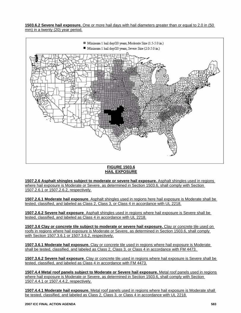
534 2007 ICC FINAL ACTION AGENDA FS103-06/07 715.3 (New), 715.3.1 (New), 715.3.2 (New), 715.3.3 (New) Proposed Change as Submitted: Proponent: Kate Steel, representing Fire & Safety Glazing Council Add new text as follows: 715.3 Classification of glazing material. Glazing material tested and rated in accordance with Section 703 and Section 715 shall be classified and labeled under the following rating classifications: 715.3.1. R-Rated glazing. Fire-resistance rated glazing determined in accordance with ASTM E119. 715.3.2. P-Rated glazing. Fire-protection rated glazing determined in accordance with NFPA 252 or NFPA 257. 715.3.3. Identification. Glazing classified in accordance with 715.3 shall be identified by a designation of R- xxx or P-xxx, where xxx states the rating period, in hours or minutes, which shall be included as a permanent mark on the labels issued in accordance with sections 706.2.1, 715.4.6.3, and 715.5.8. (Renumber subsequent sections) Reason: The classification of glazing as “R” for meeting fire-resistance and limited temperature rise criteria in accordance with ASTM E119, or “P” for fire-protection testing of fire endurance capabilities to NFPA 252 and 257, is a simple way to distinguish between two products that are both tested and listed for use in 45-and 60-minute doors, sidelites and window assemblies, where one also meets the radiant heat and temperature rise criteria of ASTM E119. The “DH-XXX” and “OH-XXX” labeling system approved last code cycle does not provide a distinction between fire-resistance and fire-protection products labeled for 45, 60-and 90-minute applications. That system is also proving to be confusing in practical application, and creates the potential for costly replacements of products shipped out and incorrectly labeled for the end-use application. The most significant inadequacy in the current DH-XXX and OH-XXX labeling system is that it does not distinguish between products that limit radiant heat transfer, and those that do not. Manufacturers and distributors who supply both types of products have pointed out that the current system provides that they mark both products the same way, and they are asking for a classification and labeling requirement that will allow them to indicate to the end user the performance distinctions in their products. Manufacturers and distributors have also pointed out the practical problems of labeling their products for a particular end use installation, when they aren’t given that information in the order process. They note that their fire-rated glazing products are tested and listed to both NFPA 252 (the door assembly fire test) and NFPA 257 (the window assembly fire test), and carry overlapping listings. More often than not, the glazing orders they receive specify the size and number of glazing panels needed, but do not indicate what the end use is, i.e., whether the installation is in a fire door or door/sidelight/transom assembly, or a window assembly. To get that information—if they can get it at all—requires substantial follow-up calls, and delays the order and supply process. Manufacturers have aptly pointed out the likely scenario of marking a product D-XXX, only to get a call from the glazing contractor that it was installed in a window assembly, and asking what to do about it because the code enforcer is calling for a different label. On large orders, where identical size panels are being shipped, some labeled DH-XXX for doors, and some OH-XXX for windows, the chances of getting the panels mixed up during the installation process, is significant. To avoid that, they can simply mark the products with both DH-XXX and OH-XXX, but then any distinction that the labeling requirement was supposed to provide the end-user, is lost. The current labeling system is cumbersome, presents practical application problems that will cost time and money to manufacturers and building owners, and, in the end, fails to achieve the important goal fire-rated glazing manufacturers and end-users share— identification of which products limit radiant heat transfer, and which don’t. The proposed classification and labeling of products as “P-XXX for fire-protection-rated, or “R-XXX” for fire-resistance rated, is simple, straight-forward, and provides that critical information. The terms “resistance “ and “protection” have specific definitions under IBC and NFPA, and the R and P classification system would help reinforce those distinctions, and provide the industry the tools to make this labeling program work. A similar classification program in Europe, where parallel designations of “I” for fire resistance (i.e., insulated) products, and “E” for fire-protection (i.e., fire endurance only) has proven widely successful, and has provided the basic framework for further clarification in specific code sections addressing permitted end-use. Cost Impact: The code change proposal will not increase the cost of construction. It may decrease costs of implementing the current labeling requirements. Analysis: As written, this code change is related to and dependent on the approval of the proponent’s code changes FS35-06/07, FS117- 05/06 and FS127-06/07 which refer to this new Section 715.3. Approval of this item without approval of the other code changes would require modification. Committee Action: Disapproved Committee Reason: The committee decided to continue with the current system of labeling. The feeling is that the current system with labels in each section is easier for the code users. The current system, which the committee just adopted 2 years ago, is working because having specific sections makes it easier to know what is required and lets people know what is required. This proposal would accept items
Transcript
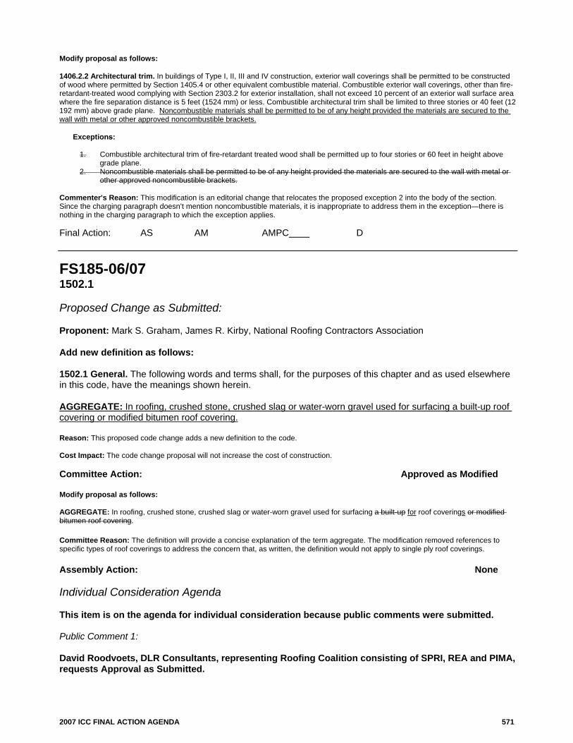
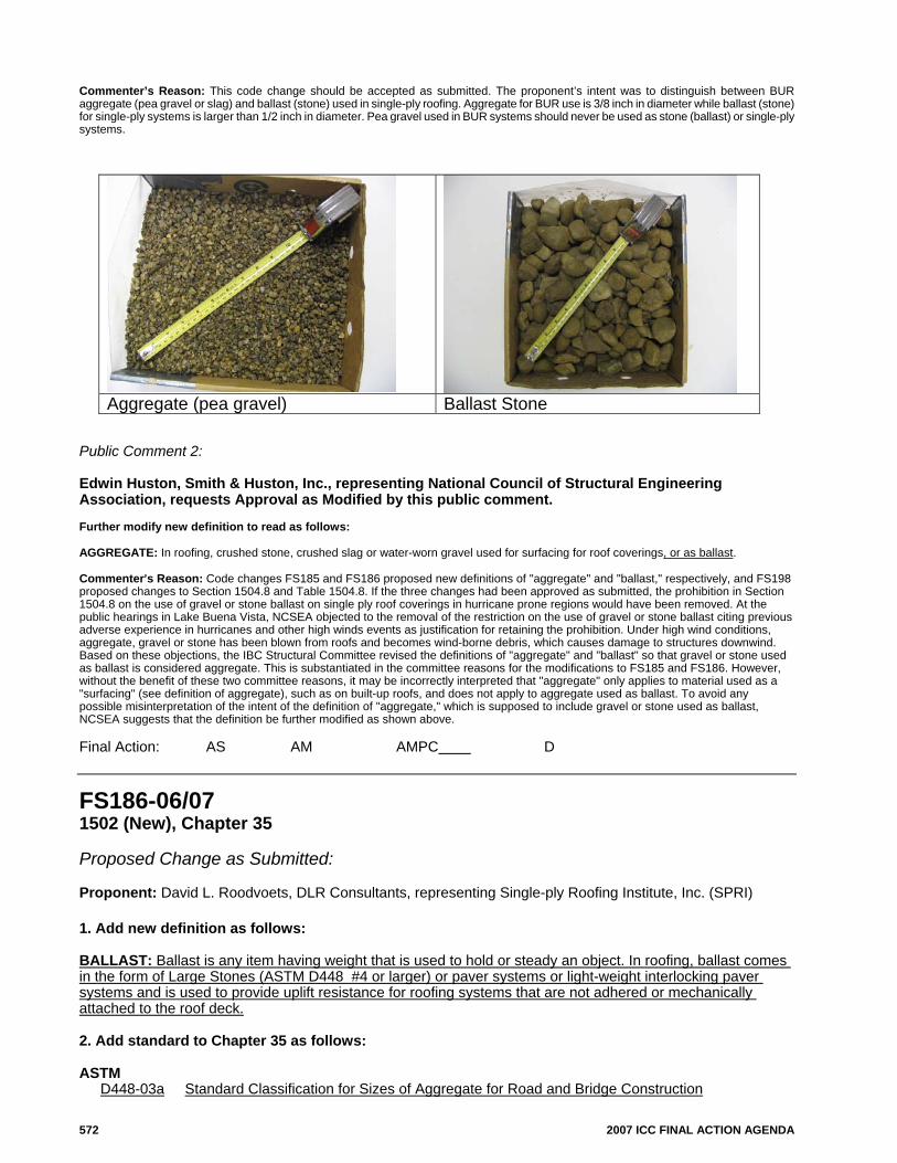
534 2007 ICC FINAL ACTION AGENDA
FS103-06/07 715.3 (New), 715.3.1 (New), 715.3.2 (New), 715.3.3 (New) Proposed Change as Submitted: Proponent: Kate Steel, representing Fire & Safety Glazing Council Add new text as follows: 715.3 Classification of glazing material. Glazing material tested and rated in accordance with Section 703 and Section 715 shall be classified and labeled under the following rating classifications: 715.3.1. R-Rated glazing. Fire-resistance rated glazing determined in accordance with ASTM E119.
715.3.2. P-Rated glazing. Fire-protection rated glazing determined in accordance with NFPA 252 or NFPA 257.
715.3.3. Identification. Glazing classified in accordance with 715.3 shall be identified by a designation of R-xxx or P-xxx, where xxx states the rating period, in hours or minutes, which shall be included as a permanent mark on the labels issued in accordance with sections 706.2.1, 715.4.6.3, and 715.5.8.
(Renumber subsequent sections) Reason: The classification of glazing as “R” for meeting fire-resistance and limited temperature rise criteria in accordance with ASTM E119, or “P” for fire-protection testing of fire endurance capabilities to NFPA 252 and 257, is a simple way to distinguish between two products that are both tested and listed for use in 45-and 60-minute doors, sidelites and window assemblies, where one also meets the radiant heat and temperature rise criteria of ASTM E119.
The “DH-XXX” and “OH-XXX” labeling system approved last code cycle does not provide a distinction between fire-resistance and fire-protection products labeled for 45, 60-and 90-minute applications. That system is also proving to be confusing in practical application, and creates the potential for costly replacements of products shipped out and incorrectly labeled for the end-use application.
The most significant inadequacy in the current DH-XXX and OH-XXX labeling system is that it does not distinguish between products that limit radiant heat transfer, and those that do not. Manufacturers and distributors who supply both types of products have pointed out that the current system provides that they mark both products the same way, and they are asking for a classification and labeling requirement that will allow them to indicate to the end user the performance distinctions in their products.
Manufacturers and distributors have also pointed out the practical problems of labeling their products for a particular end use installation, when they aren’t given that information in the order process. They note that their fire-rated glazing products are tested and listed to both NFPA 252 (the door assembly fire test) and NFPA 257 (the window assembly fire test), and carry overlapping listings. More often than not, the glazing orders they receive specify the size and number of glazing panels needed, but do not indicate what the end use is, i.e., whether the installation is in a fire door or door/sidelight/transom assembly, or a window assembly. To get that information—if they can get it at all—requires substantial follow-up calls, and delays the order and supply process. Manufacturers have aptly pointed out the likely scenario of marking a product D-XXX, only to get a call from the glazing contractor that it was installed in a window assembly, and asking what to do about it because the code enforcer is calling for a different label. On large orders, where identical size panels are being shipped, some labeled DH-XXX for doors, and some OH-XXX for windows, the chances of getting the panels mixed up during the installation process, is significant. To avoid that, they can simply mark the products with both DH-XXX and OH-XXX, but then any distinction that the labeling requirement was supposed to provide the end-user, is lost.
The current labeling system is cumbersome, presents practical application problems that will cost time and money to manufacturers and building owners, and, in the end, fails to achieve the important goal fire-rated glazing manufacturers and end-users share—identification of which products limit radiant heat transfer, and which don’t. The proposed classification and labeling of products as “P-XXX for fire-protection-rated, or “R-XXX” for fire-resistance rated, is simple, straight-forward, and provides that critical information.
The terms “resistance “ and “protection” have specific definitions under IBC and NFPA, and the R and P classification system would help reinforce those distinctions, and provide the industry the tools to make this labeling program work. A similar classification program in Europe, where parallel designations of “I” for fire resistance (i.e., insulated) products, and “E” for fire-protection (i.e., fire endurance only) has proven widely successful, and has provided the basic framework for further clarification in specific code sections addressing permitted end-use. Cost Impact: The code change proposal will not increase the cost of construction. It may decrease costs of implementing the current labeling requirements. Analysis: As written, this code change is related to and dependent on the approval of the proponent’s code changes FS35-06/07, FS117-05/06 and FS127-06/07 which refer to this new Section 715.3. Approval of this item without approval of the other code changes would require modification. Committee Action: Disapproved Committee Reason: The committee decided to continue with the current system of labeling. The feeling is that the current system with labels in each section is easier for the code users. The current system, which the committee just adopted 2 years ago, is working because having specific sections makes it easier to know what is required and lets people know what is required. This proposal would accept items
2007 ICC FINAL ACTION AGENDA 535
that are tested to NFPA 252 or NFPA 257 without a hose stream test. Glazing tested under these standards would end up being used at many locations. While currently the label would indicate that it was tested to the hose stream test, this information would not be included and could lead to misapplication. Assembly Action: None Individual Consideration Agenda This item is on the agenda for individual consideration because a public comment was submitted. Public Comment: Donn Harter, Fire & Safety Glazing Council, requests Approval as Modified by this public comment. Modify proposal as follows: 715.3 Classification of glazing material. Glazing material tested and rated in accordance with Section 703 and Section 715 shall be classified and labeled under the following rating classifications: 715.3.1 R-Rated glazing. Fire-resistance rated glazing determined in accordance with ASTM E119 shall be classified as R-Rated glazing.
715.3.2 P-Rated glazing. Fire-protection rated glazing determined in accordance with NFPA 252 or NFPA 257 shall be classified as P-Rated glazing.
715.3.3 Identification. Glazing classified in accordance with 715.3 shall be identified by a designation of R-xxx or P-xxx, where xxx states the rating period, in hours or minutes which shall be included as a permanent mark on the labels issued in accordance with Sections 706.2.1, 703.5, 715.4.6.3.1, and 715.5.8.1.1. (Renumber subsequent sections) Commenter=s Reason: The classification of glazing as “R” for meeting fire-resistance and limited temperature rise criteria in accordance with ASTM E119, or “P” for fire-protection testing of fire endurance capabilities to NFPA 252 and 257, is a simple way to distinguish between two products that are both tested and listed for use in 45-and 60-minute doors, sidelites and window assemblies, where one also meets the radiant heat and temperature rise criteria of ASTM E119.
The “DH-XXX” and “OH-XXX” labeling system approved last code cycle does not provide a distinction between fire-resistance and fire-protection products labeled for 45, 60-and 90-minute applications. That system is also proving to be confusing in practical application, and creates the potential for costly replacements of products shipped out and incorrectly labeled for the end-use application.
The most significant inadequacy in the current DH-XXX and OH-XXX labeling system is that it does not distinguish between products that limit radiant heat transfer, and those that do not. Manufacturers and distributors who supply both types of products have pointed out that the current system provides that they mark both products the same way, and they are asking for a classification and labeling requirement that will allow them to indicate to the end user the performance distinctions in their products.
The current labeling system is cumbersome, presents practical application problems that will cost time and money to manufacturers and building owners, and, in the end, fails to achieve the important goal fire-rated glazing manufacturers and end-users share—identification of which products limit radiant heat transfer, and which don’t. The proposed classification and labeling of products as “P-XXX for fire-protection-rated, or “R-XXX” for fire-resistance rated, is simple, straight-forward, and provides that critical information.
In related public comments to FS116 and FS127, the labeling system also provide for marking the hose stream test performance marking of the glazing product, which addresses the comment of the Fire Safety Committee in rejecting the original proposal because hose stream performance would not be included on the label.
In summary, the proposed public comment proposals FS35, FS103, FS116 and FS127 address the concerns of the Fire Safety Committee in disapproving those public proposals. These modified code changes provide a workable classification and labeling system that distinguishes between products that are fire-resistance rated, as opposed to fire-protection-rated, and also designate on the label whether the glazing meets the hose stream test performance requirements.
These changes will reduce the cost of construction, which are increased by implementation of the current W-XXX, D-H-NH-XXX, OH-XXX labeling provisions. Final Action: AS AM AMPC D
536 2007 ICC FINAL ACTION AGENDA
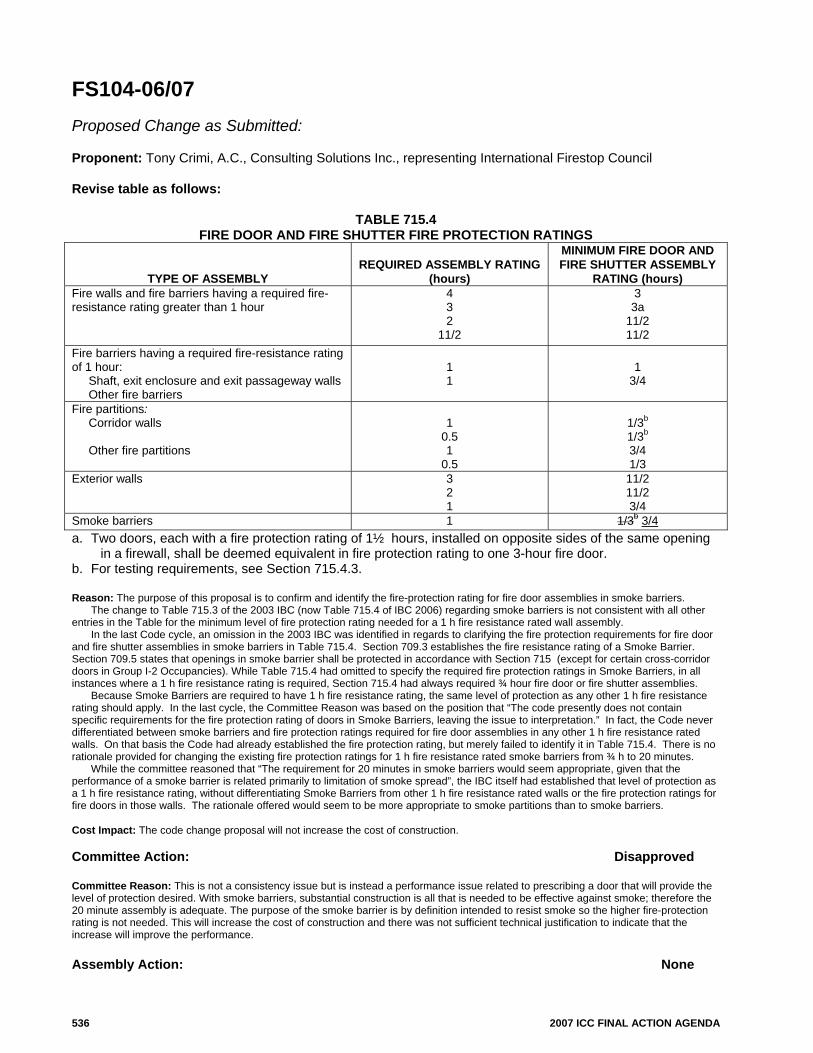
FS104-06/07 Proposed Change as Submitted: Proponent: Tony Crimi, A.C., Consulting Solutions Inc., representing International Firestop Council Revise table as follows:
TABLE 715.4 FIRE DOOR AND FIRE SHUTTER FIRE PROTECTION RATINGS
TYPE OF ASSEMBLY REQUIRED ASSEMBLY RATING
(hours)
MINIMUM FIRE DOOR AND FIRE SHUTTER ASSEMBLY
RATING (hours) Fire walls and fire barriers having a required fire-resistance rating greater than 1 hour
4 3 2
11/2
3 3a
11/2 11/2
Fire barriers having a required fire-resistance rating of 1 hour: Shaft, exit enclosure and exit passageway walls Other fire barriers
1 1
1
3/4
Fire partitions: Corridor walls Other fire partitions
1
0.5 1
0.5
1/3b 1/3b 3/4 1/3
Exterior walls
3 2 1
11/2 11/2 3/4
Smoke barriers 1 1/3b 3/4 a. Two doors, each with a fire protection rating of 1½ hours, installed on opposite sides of the same opening
in a firewall, shall be deemed equivalent in fire protection rating to one 3-hour fire door. b. For testing requirements, see Section 715.4.3. Reason: The purpose of this proposal is to confirm and identify the fire-protection rating for fire door assemblies in smoke barriers.
The change to Table 715.3 of the 2003 IBC (now Table 715.4 of IBC 2006) regarding smoke barriers is not consistent with all other entries in the Table for the minimum level of fire protection rating needed for a 1 h fire resistance rated wall assembly.
In the last Code cycle, an omission in the 2003 IBC was identified in regards to clarifying the fire protection requirements for fire door and fire shutter assemblies in smoke barriers in Table 715.4. Section 709.3 establishes the fire resistance rating of a Smoke Barrier. Section 709.5 states that openings in smoke barrier shall be protected in accordance with Section 715 (except for certain cross-corridor doors in Group I-2 Occupancies). While Table 715.4 had omitted to specify the required fire protection ratings in Smoke Barriers, in all instances where a 1 h fire resistance rating is required, Section 715.4 had always required ¾ hour fire door or fire shutter assemblies.
Because Smoke Barriers are required to have 1 h fire resistance rating, the same level of protection as any other 1 h fire resistance rating should apply. In the last cycle, the Committee Reason was based on the position that “The code presently does not contain specific requirements for the fire protection rating of doors in Smoke Barriers, leaving the issue to interpretation.” In fact, the Code never differentiated between smoke barriers and fire protection ratings required for fire door assemblies in any other 1 h fire resistance rated walls. On that basis the Code had already established the fire protection rating, but merely failed to identify it in Table 715.4. There is no rationale provided for changing the existing fire protection ratings for 1 h fire resistance rated smoke barriers from ¾ h to 20 minutes.
While the committee reasoned that “The requirement for 20 minutes in smoke barriers would seem appropriate, given that the performance of a smoke barrier is related primarily to limitation of smoke spread”, the IBC itself had established that level of protection as a 1 h fire resistance rating, without differentiating Smoke Barriers from other 1 h fire resistance rated walls or the fire protection ratings for fire doors in those walls. The rationale offered would seem to be more appropriate to smoke partitions than to smoke barriers. Cost Impact: The code change proposal will not increase the cost of construction. Committee Action: Disapproved Committee Reason: This is not a consistency issue but is instead a performance issue related to prescribing a door that will provide the level of protection desired. With smoke barriers, substantial construction is all that is needed to be effective against smoke; therefore the 20 minute assembly is adequate. The purpose of the smoke barrier is by definition intended to resist smoke so the higher fire-protection rating is not needed. This will increase the cost of construction and there was not sufficient technical justification to indicate that the increase will improve the performance. Assembly Action: None
2007 ICC FINAL ACTION AGENDA 537
Individual Consideration Agenda This item is on the agenda for individual consideration because a public comment was submitted. Public Comment: Tony Crimi, A.C., Consulting Solutions Inc., representing International Firestop Council, requests Approval as Submitted. Commenter=s Reason: The change to Table 715.3 of the 2003 IBC (now Table 715.4 of IBC 2006) regarding smoke barriers is not consistent with all other entries in the Table for the minimum level of fire protection rating needed for a 1 h fire resistance rated wall assembly. While the committee reasoned that “With smoke barriers, substantial construction is all that is needed to be effective against smoke; therefore the 20 minute assembly is adequate. The purpose of the smoke barrier is by definition intended to resist smoke so the higher fire-protection rating is not needed.”, the 2003 IBC itself had established that level of protection as a 1 h fire resistance rating, without differentiating Smoke Barriers from other 1 h fire resistance rated walls or the fire protection ratings for fire doors in those walls.
In the last Code cycle, an omission in the 2003 IBC was identified in regards to clarifying the fire protection requirements for fire door and fire shutter assemblies in smoke barriers in Table 715.4. Section 709.3 establishes the fire resistance rating of a Smoke Barrier. Section 709.5 states that openings in smoke barrier shall be protected in accordance with Section 715 (except for certain cross-corridor doors in Group I-2 Occupancies). While Table 715.4 had omitted to specify the required fire protection ratings in Smoke Barriers, in all instances where a 1 h fire resistance rating is required, Section 715.4 had always required ¾ hour fire door or fire shutter assemblies.
Because Smoke Barriers are required to have 1 h fire resistance rating, the same level of protection as any other 1 h fire resistance rating should apply. In the last cycle, the Committee Reason was based on the position that “The code presently does not contain specific requirements for the fire protection rating of doors in Smoke Barriers, leaving the issue to interpretation.” In fact, the Code never differentiated between smoke barriers and fire protection ratings required for fire door assemblies in any other 1 h fire resistance rated walls. On that basis the Code had already established the fire protection rating, but merely failed to identify it in Table 715.4. There was no rationale provided for changing the existing fire protection ratings for 1 h fire resistance rated smoke barriers from ¾ h to 20 minutes. Final Action: AS AM AMPC D
FS107-06/07 715.4.3.2 Proposed Change as Submitted: Proponent: Wayne Carson, Carson Associates Inc., SAFTIFIRST, a division of O’Keefee’s Inc. Revise as follows: 715.4.3.2 Glazing in door assemblies. In a 20-minute fire door assembly, the glazing material in the door itself shall have a minimum fire-protection rating of 20 minutes and shall be exempt from the hose stream test. Glazing material in any other part of the door assembly, including transom lites and sidelites, shall be tested in accordance with NFPA 257, including and shall be exempt from the hose stream test, in accordance with Section 715.5. Reasons: Delete current requirements for hose stream test on corridor glazing.
This code change will better align the code requirements for corridor walls and delete the inconsistency for protecting one opening (doors) from other openings (glazing) in the corridor wall.
The purpose of the corridor wall requirement was to protect the egress path from smoke and heat for the time it takes people to evacuate that floor. The one-hour wall requirement was used as a method to establish a quality of construction, a design and construction requirement that can be easily determined during plan review and inspections and not as a minimum absolute requirement of 1 hour fire resistance for protecting the corridor. The use of the 20 minute door establishes the intent of this code provision, it was not 1 hour fire resistance.
There is considerable inconsistency in the hose stream test requirement. For example, walls tested for less than one hour do not require the hose stream test, yet we test glazing over 20 minute rated.
The hose stream test is not applicable to the level of protection intended for corridors and is unnecessary. The European standards do not require the hose stream test for any glazing in fire rated construction including ISO 834-8:2002. Cost Impact: This code change will not increase the cost of construction. This code change will reduce the cost of acceptable glazing materials. Committee Action: Disapproved Committee Reason: The concern is that the door has a limited fuel load adjacent to it while a sidelight may have things in front of them or near them. By removing this limitation, it will create confusion since there is not a clear distinction between the wall and the door. Without it the only limitation would be the 25% limit and you could have a tempered glass “sidelight” taking up most of the area and be
538 2007 ICC FINAL ACTION AGENDA
susceptible to breaking with any heat differential. This has been debated and argued in NFPA 101, NFPA 80 and also the IBC legacy codes; it has always been defeated. The hose stream requirement is consistent with the NFPA 257 reference standard. It would be better to change the requirement in the standard. Assembly Action: None Individual Consideration Agenda This item is on the agenda for individual consideration because public comments were submitted. Public Comment 1: Wayne Carson, Carson Associates Inc. representing SAFTI FIRST, a division of O’Keeffe’s Inc., requests Approval as Submitted. Commenter=s Reason: The substantiation for the committee’s action is incorrect and misleading. The last full editions of the legacy codes did not include a requirement for special treatment of sidelights and transoms. Sidelights and transoms were treated as part of the door assembly and were exempt from the hose stream requirement. The SBC supplement to the 1997 edition was the first code to introduce the provision for the hose stream test for sidelights and transoms. BOCA 1999, section 717.1.1; 717.1 Fire door assemblies: Approved fire door assemblies as defined in this code shall be constructed of any material or assembly of component materials which conforms to the test requirements of NFPA 252 listed in Chapter 35 and the fire protection rating herein required in Table 717.1, unless otherwise specifically provided for in this code. Exception: Floor fire doors shall comply with Section 714.2.6 717.1.1 Twenty-minute doors: Fire doors having a fire protection rating of 20 minutes shall be tested in accordance with ASTM E152 listed in Chapter 35 without the hose stream test. SBC 1997, section 705.1.3; 705.1.3 Approved types of fire windows, doors and shutters 705.1.3.1 Wall openings required to be protected shall be protected by approved listed and labeled fire doors, windows and shutters and their accompanying hardware, including all frames, closing devises, anchorage and sills, in accordance with the requirements of NFPA 80, except as otherwise specified in the code.
705.1.3.2. Openings are classified in accordance with the character and location of the wall in which they are situated. Fire protection ratings for products intended to comply with this section shall be as determined and reported by a nationally recognized testing agency in accordance with NFPA 252 or NFPA 257. All such products shall bear an approved label. In each of the following classes, the minimum fire protection ratings are shown.
705.1.3.2.1 Fire doors are classified as 3-hour, 1-1/2 hour, 1-hour, ¾ hour or 20 minutes. 705.1.3.2.2 Unless otherwise specified, door assemblies in walls required to have a fire resistance rating of 1-hour or less shall have
a fire resistance rating of 20 minutes when tested in accordance with NFPA 252 without the hose stream. Exception: For Group I Unrestrained, corridor doors shall be in accordance with 409.41.4 UBC 1977, sections 713.7 &1004.3.4.3.2.1. Doors
713.7 Glazed Openings in Fire Doors: Glazed openings in fire doors shall not be permitted in a fire assembly required to have a three-hour fire-resistive rating. The area of glazed openings in a fire door required to have one- and one-half-hour or one-hour fire resistive rating shall be limited to 100 square inches (64 500 mm²) with a minimum dimension of 4 inches (102 mm). When both leaves of a pair of doors have observation panels, the total area of the glazed openings shall not exceed 100 square inches (64 500 mm²) for each leaf. Glazed openings shall be limited to 1,296 square inches (0.84 m²) in wood and plastic-faced composite or hollow metal doors, per light, when fire-resistive assemblies are required to have a three-fourths-hour fire-resistive rating.
1004.3.4.3.2.1 Doors. All exit-access doorways and doorways from unoccupied areas to a corridor shall be protected by tightfitting smoke- and draft-control assemblies having a fire-protection rating of not less than 20 minutes when tested in accordance with UBC Standard 7-2, Part II. Such doors shall not have louvers, mail slots or similar openings. The door and frame shall bear an approved label or other identification showing the rating thereof, followed by the letter “S”, the name of the manufacturer and the identification of the service conducting the inspection of materials and workmanship at the factory during fabrication and assembly. Doors shall be maintained self-closing or shall be automatic closing by actuation of smoke detector in accordance with Section 713.2 Smoke- and draft-control door assemblies shall be provided with a gasket installed so as to provide a seal where the door meets the stop on both sides and across the top.
Exception: View ports may be installed if they require a hole not larger than 1 inch (25 mm) in diameter through the door, have at least a ¼ inch thick (6.4mm) glass disc and the holder is of metal that will not melt out when subject to temperatures of 1,700°F (927°C).
The substantiation also states that this issue has been debated in NFPA 101 and NFPA 80 and has always been defeated. This is simply not true. NFPA 80 clearly states that the sidelights and transoms are considered part of the door assembly. NFPA 80-1999, section 1-4: Fire Door.* The door component of a fire door assembly. Fire Door Assembly. Any combination of a fire door, a frame, hardware, and other accessories that together provide a specific degree of fire protection to the opening. Fire Door Frame. A component, forming the perimeter of an opening in a fire door assembly, that is supplied welded or knocked down and anchored to the surrounding structure.
Fire Door Frame for Lights. A frame that, in addition to a door opening, contains an opening(s) for use with glazing materials. Various types include transom light, side light, and transom and side light frames. (See Figures B-66, B-67 and B-68 for elevations.)
2007 ICC FINAL ACTION AGENDA 539
NFPA 80-2007, section 3.3.52-55: 3.3.52* Fire Door. The door component of a fire door assembly. 3.3.53 Fire Door Assembly. Any combination of a fire door, a frame, hardware, and other accessories that together provide a specific degree of fire protection to the opening. 3.3.54 Fire Door Frame. A component forming the perimeter of an opening in a fire door assembly that is supplied welded or knocked down and anchored to the surrounding structure. 3.3.55* Fire Door Frame for Lights. A frame that, in addition to a door opening, contains an opening(s) for use with glazing materials. NFPA 80 does not specify separate testing for the sidelights or transoms from the glazing in the door. It simply refers to NFPA 252 for the testing of the door. 3.3.59 Fire Protection Rating. For the purposes of this standard, the designation indicating the duration of the fire test exposure to which a fire door assembly or fire window assembly was exposed and for which it successfully met all acceptance criteria as determined in accordance with NFPA 252, Standard Methods of Fire Tests of Door Assemblies, or NFPA 257, Standard on Fire Test for Window and glass Block Assemblies, respectively. (See also Annex D.) Also, NFPA 101 does not specify a separate test for sidelights and transoms. In fact when such a change was proposed to NFPA 101, the NFPA Standards Council rejected the proposed code change. A copy of the NFPA Standards Council decision is attached.
The hose stream requirement is consistent with NFPA 257 as the committee reason states; however, the introduction of NFPA 257 is inconsistent with the testing of fire rated doors as required in NFPA 252. NFPA 252 is the test standard for doors and the definition of doors clearly includes sidelights and transoms. The IBC section 715.4.3.2 now includes a conflict between the Building Code and NFPA 252.
The use of the hose stream test has never been validated as an appropriate test for evaluating the fire risk of glazing. It was originally used for cast iron columns to evaluate the risk of collapse during fire fighting operations.
The change to require separate testing of the sidelights and transoms from the testing specified in NFPA 252 for doors in the 2000 IBC was clearly to support a market position. Sidelights and transoms were used for years without the hose stream test without any documented unfavorable experience. There is no documentation to demonstrate any problem with the way the legacy codes dealt with this issue up to 1997. And there is no documentation to substation the need for separate testing of the sidelights and transoms since. We are causing the expenditure of money for glazing in sidelights when there is no documented need for such extra protection. This code change will reduce the cost of glazing in sidelights without reducing fire protection. (Editor’s note: The following document was also submitted as a part of the public comment’s reason statement.)
Decision of the Standards Council on the Complaint of W. Koffel, Koffel Associates
On Comment 101-164 for the 1997 Edition of NFPA 101, Life Safety Code®
On January 15, 1997, the Standards Council considered the complaint of W. Koffel, Koffel Associates, on behalf of O’Keefe’s Inc. The complaint sought the rejection of Comment 101-164 on the proposed 1997 edition of NFPA 101, Life Safety Code®.
Public Comment 101-164 would, in pertinent part, sharply limit an exception (which for convenience, will be referred to as “the hose stream” exception) contained in the prior edition of NFPA 101. Specifically, it would change the requirements applicable to the testing of 20-minute doors protecting openings in one hour corridor walls or smoke barriers and ½ hour fire barriers by permitting the hose stream test to be omitted only for door assemblies that do not incorporate vision panels. In the prior edition (NFPA 101-1994) all 20 minute doors were exempted form the hose stream test regardless of the presence of vision panels.
The limitation of the hose stream exception was first proposed in Public Proposal 101-128. This Proposal was rejected by the Technical Committee on Fire Protection Features and the Life Safety Technical Correlating Committee. The issue was raised again in Comment 101-164 and, this time, was Accepted in Principle by the Technical Committee and Technical Correlating Committee. A motion to reject Comment 101-164 was moved on the floor of the 1996 Fall Association Meeting. On a tie vote, the floor motion failed.
Attending a hearing on the complaints and speaking in favor of rejecting Comment 101-164 were: W. Koffel, Koffel Associates Inc. representing O’Keeffe’s Inc, and K. Steel, O’Keefe’s Inc. J. Beitel, Hughs Associates, Representing the Wired Glass Industry, was in attendance speaking in support of Comment 101-+164 as accepted in the Report on Comments.
There were numerous arguments make in the written submissions and at the hearing. Without attempting to summarize fully, some the most salient fell into the following categories. Those in favor of rejecting Comment 101-164 argued that the Comment fails to address the concerns raised by the submitter, that the testing submitted as the substantiation is not a valid reason for such a change, that the change would have a significant impact on existing assemblies without any adverse experience being documented, and that the change focuses on one specific performance characteristic which favors the wired glass industry. They also argued that the reversal of the Committee position between the Proposal and Comment stage and the tie vote of the membership at the Association Technical Meeting failed to provide a convincing evidence of consensus.
Those in favor of retaining Comment 101-164 argued that the limitation of the hose stream exception would improve safety, would eliminate inconsistency in the Code, and would close what they considered a loophole in the current requirements of NFPA 101. They also argued that test work done by one laboratory showed that one unspecified type of listed 20-minute rated glass failed early under certain circumstances when exposed to a small water spray. They also claimed that inclusion of a hose stream test would be consistent with practice in Canada and Europe.
After the hearing, the Council reviewed and considered all of the information available to it regarding the complaint and voted to uphold the complaint and reject Comment 101-164. The effect of this decision is to return to the Report on Proposals wording, which effectively retains the hose stream exception as it existed in the previous edition of NFPA 101.
Comment 101-164 has come through the standards development process with a recommendation to accept, and the Council would generally adopt that recommendation unless there were substantial reason presented for not doing so. In this case, the Council has concluded that there are substantial reasons for rejecting the Comment. The effect of this Comment would be to severely restrict the use in door assemblies of alternative types of fire rated glazings to wired glass. Because of the hose stream exception, such alternative glazings have been in use in door assemblies. The proponent of Comment 101-164, however, could point to no documented history of problems with these door assemblies. Moreover, the other arguments offered by the proponents were not persuasive. In particular, the test results offered by the proponents in favor of their position were, for reason brought out at the hearing, far from conclusive.
Prior to restricting the use of products or methods from a standard there should generally be adequate substantiation for doing so. The Council, after reviewing the entire record, does not believe that the proponents of Comment 101-164 have provided such substantiation. The Council, moreover, is influenced in its decision by the fact that, although a recommendation in favor of the Comment was technically achieved
540 2007 ICC FINAL ACTION AGENDA
under NFPA rules, there is reason to question whether a clear consensus on the issue has been achieved. The Technical Committee declined to remove the hose stream exception during the Proposal stage, and only came around to that position at the Comment stage. It did so without any clear indication of the reasons for the position change. Moreover, although the floor motion to reject the Comment failed, the membership on the floor were divided evenly on the question. In these circumstances and given the insufficiency of the substantiation in favor of the Comment, the Council believes that there is an inadequate basis to limit the hose stream exception. Of course, if further action to review and address this issue is deemed necessary, such action can be taken during the next revision cycle, or if it is determined to be of an emergency nature, through the processing of a Tentative Interim Amendment.
Council member Belles recused himself from participation in the hearing and was not present during the deliberations and vote on this issue. Note: Anyone may appeal to the Board of Directors concerning Council action on any matters in accordance with the Procedures for Appeals to the Board of Directors. Notice of the intent to file an appeal shall be submitted to the Board within 20 days of action by the Council. See section 1-7 and 3-8 of the Regulations Governing Committee Projects. SC 97-4(c)(d) D#97-3 Public Comment 2: Wayne Carson, Carson Associates Inc. representing SAFTI FIRST, a division of O’Keeffe’s Inc., requests Approval as Modified by this public comment. Modify proposal as follows: 715.4.3.2 Glazing in door assemblies. In a 20-minute fire door assembly, the glazing material in the door itself shall have a minimum fire-protection rating of 20 minutes and shall be exempt from the hose stream test. Glazing material in any other part of the door assembly greater than 30” wide, including transom lites and sidelites, shall be tested in accordance with NFPA 257 including the hose stream test, in accordance with section 715.5. Commenter=s Reason: See Public Comment 1. Final Action: AS AM AMPC D
FS113-06/07 715.4.6.1, 715.5, 715.5.3, Table 715.5.3, 715.5.4 Proposed Change as Submitted: Proponent: William F. O’Keeffe, SAFTI FIRST 1. Revise as follows: 715.4.6.1 Size limitations. Wired glass Fire-protective-rated glazing used in fire doors shall comply with Table 715.5.3. Other fire-protection-rated glazing shall comply with the size limitations of NFPA 80.
Exceptions:
1. Fire-protection-rated glazing in fire doors located in fire walls shall be prohibited except that where serving as a horizontal exit, a self-closing swinging door shall be permitted to have a vision panel of not more than 100 square inches (0.065 m2) without a dimension exceeding 10 inches (254 mm).
2. Fire-protection-rated glazing shall not be installed in fire doors having a 11/2-hour fire protection rating intended for installation in fire barriers, unless the glazing is not more than 100 square inches (0.065 m2) in area.
715.5 Fire-protection-rated glazing. Glazing in fire window assemblies shall be fire-protection rated in accordance with this section and Table 715.5. Glazing in fire door assemblies shall comply with Section 715.4.6. Fire-protection-rated glazing shall be tested in accordance with and shall meet the acceptance criteria of NFPA 257. Fire-protection-rated glazing shall also comply with NFPA 80. Openings in nonfire-resistance- rated exterior wall assemblies that require protection in accordance with Section 704.3, 704.8, 704.9 or 704.10 shall have a fire-protection rating of not less than ¾ hour.
Exceptions:
1. Wired glass in accordance with Section 715.5.3. 2. Fire-protection-rated glazing in 0.5-hour fire-resistance-rated partitions is permitted to have an 0.33-hour
fire protection rating.
2007 ICC FINAL ACTION AGENDA 541
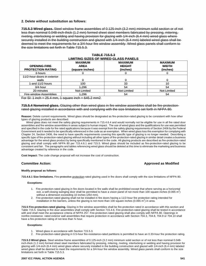
2. Delete without substitution as follows: 715.5.3 Wired glass. Steel window frame assemblies of 0.125-inch (3.2 mm) minimum solid section or of not less than nominal 0.048-inch-thick (1.2 mm) formed sheet steel members fabricated by pressing, mitering, riveting, interlocking or welding and having provision for glazing with 1/4-inch (6.4 mm) wired glass where securely installed in the building construction and glazed with 1/4-inch (6.4 mm) labeled wired glass shall be deemed to meet the requirements for a 3/4-hour fire window assembly. Wired glass panels shall conform to the size limitations set forth in Table 715.5.3.
TABLE 715.5.3 LIMITING SIZES OF WIRED GLASS PANELS
OPENING FIRE PROTECTION RATING
MAXIMUM AREA
(square inches)
MAXIMUM HEIGHT (inches)
MAXIMUM WIDTH
(inches) 3 hours 0 0 0
11/2-hour doors in exterior walls 0 0 0
1 and 11/2 hours 100 33 10 3/4 hour 1,296 54 54
20 minutes Not Limited Not Limited Not Limited Fire window Assemblies 1,296 54 54
For SI: 1 inch = 25.4 mm, 1 square inch = 645.2 mm2. 715.5.4 Nonwired glass. Glazing other than wired glass in fire window assemblies shall be fire-protection-rated glazing installed in accordance with and complying with the size limitations set forth in NFPA 80. Reason: Delete current requirements. Wired glass should be designated as fire-protection-rated glazing to be consistent with how other types of glazing products are described.
Wired glass does not meet the safety glazing requirements in 715.4.6.4 and would normally not be eligible for use in all fire rated door assemblies and fire window assemblies in areas subject to human impact. The use of wired glass and the qualifications for use was permitted and specified in the code for fire rated applications because it was exempt from the safety glazing requirements of Section 2406 by the Federal Government and it needed to be specifically referenced in the code as an exemption. When wired glass loss this exemption for complying with Chapter 24, Section 2406, the need to have specific requirements covering this specific type of glazing is no longer needed. Describing a specific type of fire-protection-rated glazing without including all other types of fire-protection-rated glazing in similar detail creates a business advantage for the wired glass product by being specifically mentioned in the code. All glazing products are described as fire-protection-rated glazing and shall comply with NFPA 80 per 715.4.6.1 and 715.5. Wired glass should be included as fire-protection-rated glazing to be consistent and fair. The paragraphs and tables referencing wired glass should be deleted at this time to eliminate the marketing and business advantage created by reference in the code. Cost Impact: The code change proposal will not increase the cost of construction. Committee Action: Approved as Modified Modify proposal as follows: 715.4.6.1 Size limitations. Fire-protective protection-rated glazing used in fire doors shall comply with the size limitations of NFPA 80. Exceptions:
1. Fire-protection-rated glazing in fire doors located in fire walls shall be prohibited except that where serving as a horizontal exit, a self-closing swinging door shall be permitted to have a vision panel of not more than 100 square inches (0.065 m2) without a dimension exceeding 10 inches (254 mm).
2. Fire-protection-rated glazing shall not be installed in fire doors having a 11/2-hour fire protection rating intended for installation in fire barriers, unless the glazing is not more than 100 square inches (0.065 m2) in area.
715.5 Fire-protection-rated glazing. Glazing in fire window assemblies shall be fire-protection rated in accordance with this section and Table 715.5. Glazing in fire door assemblies shall comply with Section 715.4.6. Fire-protection-rated glazing shall be tested in accordance with and shall meet the acceptance criteria of NFPA 257. Fire-protection-rated glazing shall also comply with NFPA 80. Openings in nonfire-resistance- rated exterior wall assemblies that require protection in accordance with Section 704.3, 704.8, 704.9 or 704.10 shall have a fire-protection rating of not less than ¾ hour. Exceptions:
1. Wired glass in accordance with Section 715.5.3. 2. Fire-protection-rated glazing in 0.5-hour fire-resistance-rated partitions is permitted to have an 0.33-hour fire protection rating.
715.5.3 Wired glass. Steel window frame assemblies of 0.125-inch (3.2 mm) minimum solid section or of not less than nominal 0.048-inch-thick (1.2 mm) formed sheet steel members fabricated by pressing, mitering, riveting, interlocking or welding and having provision for glazing with 1/4-inch (6.4 mm) wired glass where securely installed in the building construction and glazed with 1/4-inch (6.4 mm) labeled wired glass shall be deemed to meet the requirements for a 3/4-hour fire window assembly. Wired glass panels shall conform to the size limitations set forth in Table 715.5.3.
542 2007 ICC FINAL ACTION AGENDA
TABLE 715.5.3 LIMITING SIZES OF WIRED GLASS PANELS
OPENING FIRE PROTECTION RATING
MAXIMUM AREA
(square inches)
MAXIMUM HEIGHT (inches)
MAXIMUM WIDTH (inches)
3 hours 0 0 0 11/2-hour doors in exterior
walls 0 0 0 1 and 11/2 hours 100 33 10
3/4 hour 1,296 54 54 20 minutes Not Limited Not Limited Not Limited
Fire window Assemblies 1,296 54 54 For SI: 1 inch = 25.4 mm, 1 square inch = 645.2 mm2. 715.5.4 Nonwired glass. Glazing other than wired glass in fire window assemblies shall be fire-protection-rated glazing installed in accordance with and complying with the size limitations set forth in NFPA 80. Committee Reason: Wired glass is no longer permitted as a safety glazing in hazardous locations. Therefore Section 715.4.6.1 should not include wired glass since it may not be used in the doors which are considered as a hazardous location. Additionally, the code should not be product specific but should address the required performance. The committee modified the proposal to keep Section 715.5 exception 1 and also keep all of the text which was proposed to be deleted in item 2 of this proposal. The modification recognizes that the code has historically accepted wired-glass in a steel frame as equivalent to a 3/4-hour assembly. The deletion of this section and table would require a listed frame which would increase the cost of construction without justification supporting such a change. The listing of wired-glass assemblies use the steel frames specified in this section during their testing. These prescriptive steel frame products have worked well historically and the option of using this should remain in the code. The change to “fire-protection” instead of “fire-protective” in Section 715.4.6.1 is an editorial change and not a modification by the committee. This aspect of the change was discussed during the hearings and ruled to be editorial. Assembly Action: None Individual Consideration Agenda This item is on the agenda for individual consideration because public comments were submitted. Public Comment 1: William F. O’Keeffe, SAFTI FIRST, requests Approval as Modified by this public comment. Further modify proposal as follows: 715.5 Fire-protection-rated glazing. Glazing in fire window assemblies shall be fire-protection rated in accordance with this section and Table 715.5. Glazing in fire door assemblies shall comply with Section 715.4.6. Fire-protection-rated glazing shall be tested in accordance with and shall meet the acceptance criteria of NFPA 257. Fire-protection-rated glazing shall also comply with NFPA 80. Openings in nonfire-resistance-rated exterior wall assemblies that require protection in accordance with Section 704.3, 704.8, 704.9 or 704.10 shall have a fire protection rating of not less than 3/4 hour. Exceptions:
1. Wired glass in accordance with Section 715.5.3 2. Fire-protection-rated glazing in 0.5-hour fire-resistance-rated partitions is permitted to have an 0.33-hour fire-protection
rating.
715.5.3 Wired glass. Steel window frame assemblies of 0.125-inch (3.2 mm) minimum solid section or of not less than nominal 0.048-inch-thick (1.2mm) formed sheet steel members fabricated by pressing, mitering, riveting, interlocking or welding and having provision for glazing with 1/4-inch (6.4 mm) wired glass where securely installed in the building construction and glazed with 1/4-inch (6.4 mm) labeled wired glass shall be deemed to meet the requirements for a 3/4-hour fire window assembly. Wired glass panels shall conform to the size limitations set forth in Table 715.5.3.
Table 715.5.3 Limiting Sizes of Wired Glass Panels
Opening Fire Protection
Rating
Maximum Area
(square inches)
Maximum Height
(Inches)
Maximum Width
(Inches) 3 hours 0 0 0
1-1/2 hour doors in exterior walls
0 0 0
1 and 1-1/2 hours 100 33 10 3/4 hour 1,296 54 54
20 minutes Not limited Not limited Not limited Fire window Assemblies
1,296 54 54
For SI: 1 inch = 25.4 mm, 1 square inch = 645.2 mm2.
2007 ICC FINAL ACTION AGENDA 543
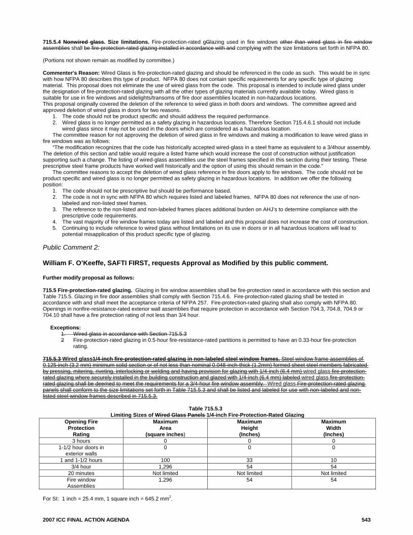
715.5.4 Nonwired glass. Size limitations. Fire-protection-rated gGlazing used in fire windows other than wired glass in fire window assemblies shall be fire-protection-rated glazing installed in accordance with and complying with the size limitations set forth in NFPA 80. (Portions not shown remain as modified by committee.) Commenter=s Reason: Wired Glass is fire-protection-rated glazing and should be referenced in the code as such. This would be in sync with how NFPA 80 describes this type of product. NFPA 80 does not contain specific requirements for any specific type of glazing material. This proposal does not eliminate the use of wired glass from the code. This proposal is intended to include wired glass under the designation of fire-protection-rated glazing with all the other types of glazing materials currently available today. Wired glass is suitable for use in fire windows and sidelights/transoms of fire door assemblies located in non-hazardous locations. This proposal originally covered the deletion of the reference to wired glass in both doors and windows. The committee agreed and approved deletion of wired glass in doors for two reasons.
1. The code should not be product specific and should address the required performance. 2. Wired glass is no longer permitted as a safety glazing in hazardous locations. Therefore Section 715.4.6.1 should not include
wired glass since it may not be used in the doors which are considered as a hazardous location. The committee reason for not approving the deletion of wired glass in fire windows and making a modification to leave wired glass in fire windows was as follows: “The modification recognizes that the code has historically accepted wired-glass in a steel frame as equivalent to a 3/4hour assembly. The deletion of this section and table would require a listed frame which would increase the cost of construction without justification supporting such a change. The listing of wired-glass assemblies use the steel frames specified in this section during their testing. These prescriptive steel frame products have worked well historically and the option of using this should remain in the code.” The committee reasons to accept the deletion of wired glass reference in fire doors apply to fire windows. The code should not be product specific and wired glass is no longer permitted as safety glazing in hazardous locations. In addition we offer the following position:
1. The code should not be prescriptive but should be performance based. 2. The code is not in sync with NFPA 80 which requires listed and labeled frames. NFPA 80 does not reference the use of non-
labeled and non-listed steel frames. 3. The reference to the non-listed and non-labeled frames places additional burden on AHJ’s to determine compliance with the
prescriptive code requirements. 4. The vast majority of fire window frames today are listed and labeled and this proposal does not increase the cost of construction. 5. Continuing to include reference to wired glass without limitations on its use in doors or in all hazardous locations will lead to
potential misapplication of this product specific type of glazing. Public Comment 2: William F. O’Keeffe, SAFTI FIRST, requests Approval as Modified by this public comment. Further modify proposal as follows: 715.5 Fire-protection-rated glazing. Glazing in fire window assemblies shall be fire-protection rated in accordance with this section and Table 715.5. Glazing in fire door assemblies shall comply with Section 715.4.6. Fire-protection-rated glazing shall be tested in accordance with and shall meet the acceptance criteria of NFPA 257. Fire-protection-rated glazing shall also comply with NFPA 80. Openings in nonfire-resistance-rated exterior wall assemblies that require protection in accordance with Section 704.3, 704.8, 704.9 or 704.10 shall have a fire protection rating of not less than 3/4 hour. Exceptions:
1. Wired glass in accordance with Section 715.5.3 2 Fire-protection-rated glazing in 0.5-hour fire-resistance-rated partitions is permitted to have an 0.33-hour fire-protection
rating.
715.5.3 Wired glass1/4-inch fire-protection-rated glazing in non-labeled steel window frames. Steel window frame assemblies of 0.125-inch (3.2 mm) minimum solid section or of not less than nominal 0.048-inch-thick (1.2mm) formed sheet steel members fabricated by pressing, mitering, riveting, interlocking or welding and having provision for glazing with 1/4-inch (6.4 mm) wired glass fire-protection-rated glazing where securely installed in the building construction and glazed with 1/4-inch (6.4 mm) labeled wired glass fire-protection-rated glazing shall be deemed to meet the requirements for a 3/4-hour fire window assembly. Wired glass Fire-protection-rated glazing panels shall conform to the size limitations set forth in Table 715.5.3 and shall be listed and labeled for use with non-labeled and non-listed steel window frames described in 715.5.3.
20 minutes Not limited Not limited Not limited Fire window Assemblies
1,296 54 54
For SI: 1 inch = 25.4 mm, 1 square inch = 645.2 mm2.
544 2007 ICC FINAL ACTION AGENDA
715.5.4 Nonwired glass. Size limitations. Fire-protection-rated gGlazing used in fire windows other than wired glass in fire window assemblies shall be fire-protection-rated glazing installed in accordance with and complying with the size limitations set forth in NFPA 80. Commenter=s Reason: Wired Glass is fire-protection-rated glazing and should be referenced in the code as such. This would be in sync with how NFPA 80 describes this type of product. NFPA 80 does not contain specific requirements for any specific type of glazing material. This proposal does not eliminate the use of wired glass from the code. This proposal is intended to include wired glass under the designation of fire-protection-rated glazing with all the other types of glazing materials currently available today.
This proposal originally covered the deletion of the reference to wired glass in both doors and windows. The committee agreed and approved deletion of wired glass in doors for two reasons.
1. The code should not be product specific and should address the required performance. 2. Wired glass is no longer permitted as a safety glazing in hazardous locations. Therefore Section 715.4.6.1 should not include
wired glass since it may not be used in the doors which are considered as a hazardous location. The committee reason for not approving the deletion of wired glass in fire windows and making a modification to leave wired glass in
fire windows was as follows: “The modification recognizes that the code has historically accepted wired-glass in a steel frame as equivalent to a 3/4hour
assembly. The deletion of this section and table would require a listed frame which would increase the cost of construction without justification supporting such a change. The listing of wired-glass assemblies use the steel frames specified in this section during their testing. These prescriptive steel frame products have worked well historically and the option of using this should remain in the code.”
The committee reasons to accept the deletion of wired glass reference in fire doors apply to fire windows. The code should not be product specific.
To address the need to maintain the non-listed and non-labeled steel frame construction, the reference to 1/4-inch wired glass has been updated to 1/4-inch fire-protection-rated glazing. This change will maintain the non-labeled and non-listed steel frame construction while deleting the product specific designation of wired glass and replacing it with terminology consistent with the code. 1/4-inch fire-protection-rated glazing will need to be listed and labeled for use in the steel window frames described in 715.5.3. Final Action: AS AM AMPC D
FS117-06/07 715.4.6.3, 715.4.6.3.1 Proposed Change as Submitted: Proponent: Kate Steel, representing Fire & Safety Glazing Council 1. Revise as follows: 715.4.6.3 Labeling requirements. Fire-protection-rated and fire-resistance rated glazing shall bear a label or other identification showing the name of the manufacturer, the test standard and information required in Section 715.5.8.1 the classification required in Section 715.3.3, that shall be issued by an approved agency and shall be permanently affixed to the glazing. 2. Delete without substitution as follows: 715.4.6.3.1 Identification. For fire-protection-rated glazing, the label shall bear the following four-part identification: “D – H or NH – T or NT – XXX.” “D” indicates that the glazing shall be used in fire door assemblies and that the glazing meets the fire resistance requirements of the test standard. “H” shall indicate that the glazing meets the hose stream requirements of the test standard. “NH” shall indicate that the glazing does not meet the hose stream requirements of the test. “T” shall indicate that the glazing meets the temperature requirements of Section 715.4.4.1. “NT” shall indicate that the glazing does not meet the temperature requirements of Section 715.4.4.1. The placeholder “XXX” shall specify the fire-protection-rating period, in minutes. Reason: This proposal coordinates with proposed new Section 715.3, for classification of glazing as “R” for meeting fire-resistance and limited temperature rise criteria in accordance with ASTM E119, or “P” for fire-protection testing of fire endurance capabilities to NFPA 252 and 257. These designations are a simple way to distinguish between two products that are both tested and listed for use in 45-, 60- and 90-minute doors, sidelites and window assemblies, where one also meets the radiant heat and temperature rise criteria of ASTM E119. See Reason in support of new section 715.3. Cost Impact: The code change proposal will not increase the cost of construction. Analysis: As written, this code change is related to and dependent on the approval of the proponent’s code change FS103-06/07 which adds a new Section 715.3. Approval of this item without approval of the other code change would require modification. Committee Action: Disapproved Committee Reason: This action is taken to be consistent with the action taken on FS103-06/07. Since FS103-06/07 was not approved, this item which is dependent upon it should not be accepted. Assembly Action: None
2007 ICC FINAL ACTION AGENDA 545
Individual Consideration Agenda This item is on the agenda for individual consideration because a public comment was submitted. Public Comment: Donn Harter, representing Fire & Safety Glazing Council, requests Approval as Modified by this public comment. Modify proposal as follows: 715.4.6.3.1. Identification. For fire protection rated glazing, the label shall bear the following four three part identification “P D-H or NH—T or NT-XXX.” “P D” indicates the glazing shall be used in fire door assemblies and meets the fire resistance protection requirements of the test standard required on the label in accordance with 715.4.6.3, for use in fire door assemblies. “H” shall indicate that the glazing meets the hose stream requirements of the test standard. “NH shall indicate that the glazing does not meet the hose stream requirements of the test. “T” shall indicate that the glazing meets the temperature rise requirements of section 715.4.4.1. “NT” shall indicate that the glazing does not meet the temperature rise requirements of section 715.4.4.1. The placeholder “XXX” shall specify the fire protection rating period, in minutes. Commenter=s Reason: This proposal coordinates with public comments on FS35-06/07, FS103-06/07, and FS127-06/07. In sum, the FSGC is proposing a simplified labeling system that marks glazing as R-XXX (instead of W-XXX) indicating its fire-resistance rated performance, or P-H or NH-XXX, indicating its fire-protection and hose stream tested performance, regardless of its end use application in a wall, door or window assembly. The Council recognizes the IBC Fire Safety Committee’s reasoning in rejecting its proposal, FS103-06/07, was that there was a benefit to identifying as a code requirement the designation of hose stream testing. This public comment proposal provides for that labeling of that aspect of fire performance as well. This public comment proposal also eliminates the labeling of T or NT as redundant, since the Committee’s action in accepting FS101 now provides for the labeling of fire resistance rated glazing as W-XXX when used in fire door and window assemblies, and the designation of glazing as W-XXX” under the current system means by definition that it meets the temperature rise requirements of ASTM E119. Of course, the Council is proposing in Public Comment to FS35-06/07 and FS36-06/07 that the designation of “W” be changed to “R” to reflect its fire resistance performance. The R-XXX designation for meeting fire-resistance and limited temperature rise criteria in accordance with ASTM E119, or “P-H or NH-XXX” designation for fire-protection testing of fire endurance and hose stream capabilities to NFPA 252 and 257, are straightforward markings of distinct fire performance characteristics. These designations are a simple way to distinguish between two products that are both tested and listed for use in 45-, 60- and 90-minute doors, sidelites and window assemblies, where one also meets the radiant heat and temperature rise criteria of ASTM E119. As a practical matter, fire-protection-rated products have multiple, overlapping listings for use in fire doors, transoms, sidelights and window assemblies. Accordingly, there is no need to require that the glazing be marked according to its end use application, as D for door assemblies, or O for window assemblies, because the glazing provides the same fire protection performance when it is listed for protecting both door and window openings. That additional end use marking requirement is burdensome to manufacturers, distributors, and glazing contractors, and will ultimately increase the cost to the end user, as explained in the following letter from Donn Harter to US Glass Magazine Editor. These code changes are expected to reduce costs. AGA Response To Thom Zaremba’s Letter to the Editor, “Labeling Glass for Fire and Life Safety” Dear Editor: As President of the Americas Glass Association (“AGA”), and Co-Chair of the Fire and Safety Glazing Council (“FSGC”), I would like to comment on the “Pilkington plan” for labeling fire rated glazing under the 2006 IBC, and point out the difficulties glazing contractors will face in trying to apply this labeling system. Although the glazing contractor sector of the industry had no input into the development of the Pilkington plan, they will perhaps be most affected by its application in the field, starting with the ordering process, and ending with installation at the job site. To begin with, instead of simply requesting from the manufacturer the number of fire-protection rated glazing panels with a specified time rating that are listed for use in doors, sidelights and windows, under the Pilkington plan, the glazier will have to specify the precise marking for each piece according to its end-use installation. For example, if the same 45-minute fire rated product is to be used in a door vision light, it must be marked D-45 H or NH, NT or T, but if used in a window, it must be marked OH-45. It isn’t clear under the Pilkington plan how to mark this same 45-minute product when used in sidelights and transoms, i.e., D-45 for a door assembly, or OH-45 for a window opening. If the glazing contractor specifies the wrong markings, he will have to reorder the glazing properly labeled for the end use. What happens at the jobsite when the glazing is installed? Let’s say the installer has a rack of 100 pieces of the same-size 45-minute fire protections-rated glazing. If the glazier puts a D-45 marked panel in a window opening, or an OH marked glazing in a door light, then he will have to absorb the added labor costs of going back out to the job and making the installation correction. Or, if he doesn’t have the right marked glazing for the opening, then he will have to reorder glass from the manufacturer. Now, all this extra effort might make some sense if it meant an improved level of fire safety. But when we are talking about marking a fire-protection rated product that has multiple listings in the same sizes for use in doors, sidelights/transoms and windows, and provides the same level of fire performance regardless of which opening it is in, where is the fire safety benefit of having the glazier specify a marking for the end use installation? This system invites difficulties for the glazing contractor from start to finish, and will require extra labor costs to sort through the labeling requirements, not to mention the added cost or reordering a correctly marked piece of glazing when a mistake is made—which is inevitable. This is one of the reasons the AGA, and Fire & Safety Glazing Council, supports labeling products according to their fire performance level---“P” for fire protection, and “R” for fire resistance. Those are the most important performance distinctions to be made, and this alternative system is a simple, effective way to communicate that information to the end-user. Final Action: AS AM AMPC D
546 2007 ICC FINAL ACTION AGENDA
FS118-06/07 715.4.6.4, 715.5.3 (New) Proposed Change as Submitted: Proponent: William E. Koffel, P.E., Koffel Associates, Inc., representing Fire Rated Glazing Industry 1. Revise as follows: 715.4.6.4 Safety glazing. Fire-protection-rated glazing installed in fire doors or fire window assemblies in areas subject to human impact in hazardous locations shall comply with Chapter 24. 2. Add new text as follows: 715.5.3 Safety glazing. Fire-protection-rated glazing installed in fire window assemblies in areas subject to human impact in hazardous locations shall comply with Chapter 24. (Renumber subsequent sections) Reason: Section 715.4.6 applies to glazing in fire door assemblies and therefore the requirement for safety glazing in fire window assemblies in incorrectly included in Section 715.4.6.4. The proposal retains the requirement but adds a new section in the fire window section (715.5) to reference the appropriate safety glazing requirements. Cost Impact: The code change proposal will not increase the cost of construction. Committee Action: Approved as Submitted Committee Reason: This proposal moves the requirement to a more appropriate section. This requirement for fire windows is difficult to find where it currently exists because the section it is currently in is applicable to doors. Assembly Action: None Individual Consideration Agenda This item is on the agenda for individual consideration because a public comment was submitted. Public Comment: William F. O’Keeffe, SAFTI FIRST, requests Approval as Modified by this public comment. Modify proposal as follows: 715.4.6.4 Safety glazing. Fire-protection-rated glazing installed in fire doors in areas subject to human impact in hazardous locations shall comply with Chapter 24 and the definition of hazardous locations as defined in Chapter 24, Section 2406. 715.5.3 Safety glazing. Fire-protection-rated glazing installed in fire window assemblies in areas subject to human impact in hazardous locations shall comply with Chapter 24 and the definition of hazardous locations as defined in Chapter 24, Section 2406. Commenter=s Reason: Presently hazardous location is referenced in the code but the code does not indicate where you can find the definition of hazardous location. With this clarification, where to find the definition of hazardous location in the code is specified. Final Action: AS AM AMPC D
FS121-06/07 715.5 Proposed Change as Submitted: Proponent: Wayne Carson, Carson Associates, Inc., representing SAFTFIRST Revise as follows: 715.5 Fire-protection-rated glazing. Glazing in fire window assemblies shall be fire-protection rated in accordance with this section and Table 715.5. Glazing in fire door assemblies shall comply with Section 715.4.6. Fire-protection-rated glazing shall be tested in accordance with and shall meet the acceptance criteria
2007 ICC FINAL ACTION AGENDA 547
of NFPA 257. Fire-protection-rated glazing shall also comply with NFPA 80. Openings in nonfire-resistance-rated exterior wall assemblies that require protection in accordance with Section 704.3, 704.8, 704.9 or 704.10 shall have a fire-protection rating of not less than 3/4 hour.
Exceptions:
1. Wired glass in accordance with Section 715.5.3. 2. Fire-protection-rated glazing in 0.5-hour fire-resistance-rated partitions is permitted to have an 0.33-
hour fire-protection rating. 3. Glazing in 1 hour corridor walls constructed in accordance with Section 1017.1 shall be exempt from
the hose stream test requirement. Reason: The purpose of the proposed code change is to delete current requirements for hose stream test on corridor glazing. This code change will better align the code requirements for corridor walls and delete the inconsistency for protecting one opening (doors) from other openings (glazing) in the corridor wall.
The purpose of the corridor wall requirement was to protect the egress path from smoke and heat for the time it takes people to evacuate that floor. The one-hour wall requirement was used as a method to establish a quality of construction, a design and construction requirement that can be easily determined during plan review and inspections and not as a minimum absolute requirement of 1 hour fire resistance for protecting the corridor. The use of the 20 minute door establishes the intent of this code provision, it was not 1 hour fire resistance. There is considerable inconsistency in the hose stream test requirement. For example, walls tested for less than one hour do not require the hose stream test, yet we test glazing over 20 minute rated. The hose stream test is not applicable to the level of protection intended for corridors and is unnecessary. The European standards do not require the hose stream test for any glazing in fire rated construction including ISO 834-8:2002. Cost Impact: The code change proposal will reduce the cost of construction by reducing the cost of acceptable glazing materials. Committee Action: Disapproved Committee Reason: The committee felt that this proposal would reduce the level of life safety which the code has generally required and provided. This action also coordinates with the committee’s previous action of disapproved taken on FS107-06/07 which would have eliminated the hose-stream test for glazing in doors. While the support for this proposal was somewhat based on the method of European requirements, this was not accepted by the committee. The two main concerns with the European standards were that their glazing ratings are tested to destruction, therefore the hose stream can not be used. Additionally the argument was made that we should continue to set our requirements based on what we feel is right and not on what others do, especially when they are testing differently. Approval of this proposal would also establish an inconsistency with Exception 2. If this proposal is approved, the glazing in a 0.5-hour rated corridor would require the hose-stream test while that in a 1-hour corridor would not. Assembly Action: None Individual Consideration Agenda This item is on the agenda for individual consideration because a public comment was submitted. Public Comment: Wayne Carson, Carson Associates, Inc., representing SAFTI FIREST, a division of O’Keeffe’s Inc., requests Approval as Submitted. Commenter=s Reason: The requirement for the one-hour corridor wall was primarily based on a quality of construction, rather than a specific fire resistance. The purpose of this requirement is to keep smoke and heat out of the corridor for the time required to evacuate that floor. That is why a ¾ hour door was never required, only a 20 minute door.
The glazing in a window in the corridor also has the same purpose. Some glazing materials that will pass the hose stream test have little ability to prevent radiant heat from passing through and therefore may prevent passage in the corridor from a fire in a room. The hose stream will be applied by the responding fire department and evacuation of the fire floor is likely complete by that time. There is no test data to show that activation of a sprinkler will cause the glazing to fall out.
The committees reason regarding testing to destruction in the European standards is of little practical application when considering the purpose of the corridor wall. Destruction will occur after the 20 minute time period and is therefore meaningless. Fire testing does do consider re-usability after fire exposure.
The storage of fuels against the glazing as noted in the committees reason has nothing to do with the hose stream test. This is more of an issue with radiant heat transmission than with any stresses that may be created by the application of water. It is important to note that some of the glazing materials that will pass the hose stream test will allow almost 100% of the radiant heat from a fire to pass through. If fuel storage next to the glazing is a concern, then the committee should be considering a radiant heat transfer requirement for the glazing, not a hose stream requirement. Final Action: AS AM AMPC D
548 2007 ICC FINAL ACTION AGENDA
FS127-06/07 715.5.8, 715.8.1 Proposed Change as Submitted: Proponent: Kate Steel, Piedmont, CA, representing Fire & Safety Glazing Council 1. Revise as follows: 715.5.8 Labeling requirements. Fire-protection-rated and fire-resistance rated glazing shall bear a label or other identification showing the name of the manufacturer, the test standard and information required in Section 715.5.8.1 the classification required in Section 715.3.3, that shall be issued by an approved agency and shall be permanently affixed to the glazing. 2. Delete without substitution: 715.5.8.1 Identification. For fire-protection-rated glazing, the label shall bear the following two-part identification: “OH – XXX.” “OH” indicates that the glazing meets both the fire-resistance and the hose-stream requirements of NFPA 257 and is permitted to be used in openings. “XXX” represents the fire-protection rating period, in minutes, that was tested. Reason: This proposal coordinates with proposed new Section 715.3, for classification of glazing as “R” for meeting fire-resistance and limited temperature rise criteria in accordance with ASTM E119, or “P” for fire-protection testing of fire endurance capabilities to NFPA 252 and 257. These designations are a simple way to distinguish between two products that are both tested and listed for use in 45-, 60- and 90-minute doors, sidelites and window assemblies, where one also meets the radiant heat and temperature rise criteria of ASTM E119. See Reason in support of new section 715.3. Cost Impact: The code change proposal will not increase the cost of construction. Analysis: As written, this code change is related to and dependent on the approval of the proponent’s code change FS103-06/07 which adds a new Section 715.3. Approval of this item without approval of the other code change would require modification. Committee Action: Disapproved Committee Reason: Based upon actions taken previously with items FS103 and FS117. As stated in the analysis, approval of this item without the approval of FS103 would require additional needed modifications in order to fit into the code. Assembly Action: None Individual Consideration Agenda This item is on the agenda for individual consideration because a public comment was submitted. Public Comment: Donn Harter, Fire and Safety Glazing Council, requests Approval as Modified by this public comment. Modify proposal as follows: Revise 715.5.8.1 as follows: 715.5.8.1 Identification. For fire-protection-rated glazing, the label shall bear the following two three-part identification “O P, H or NH– XXX” “OH P” indicates that the glazing meets both the fire-resistance protection and the hose stream requirements of the test standard required on the label in accordance with 715.5.8, NFPA 257 and is permitted to be used in fire window assemblies openings. “H” shall indicate that the glazing meets the hose stream requirements of the test standard. “NH shall indicate that the glazing does not meet the hose stream requirements of the test. “XXX” represents the fire-protection-rating period in minutes, that was tested. (Portions of proposal not shown remain unchanged) Commenter=s Reason: This proposal coordinates with Public Comments to FS35-06/07, FS103, and FS116-06/07, which collectively provide for classifying and labeling glazing as “R” for meeting fire-resistance and limited temperature rise criteria in accordance with ASTM E119, or “P” for fire-protection testing of fire endurance capabilities to NFPA 252 and 257. These designations are a simple way to distinguish between two products that are both tested and listed for use in 45-, 60- and 90-minute doors, sidelites and window assemblies, where one also meets the radiant heat and temperature rise criteria of ASTM E119.
2007 ICC FINAL ACTION AGENDA 549
This public comment proposal conforms to parallel language in section 715.4.6.3.1 providing for marking of H or NH on the label to indicate whether the product meets the hose stream testing portion of the test standard. It also makes editorial changes to make this section consistent with the labeling requirement language in Section 715.4.6.3.1. It also eliminates the ambiguous use of the term “opening,” and specifies the term fire window assemblies. Final Action: AS AM AMPC D
FS135-06/07 716.5.3 (IMC 607.5.5) Proposed Change as Submitted: Proponent: Michael Perrino, Code Consultants, Inc
Revise as follows: 716.5.3 (IMC 607.5.5) Shaft enclosures. Shaft enclosures that are permitted to be penetrated by ducts and air transfer openings shall be protected with approved fire and smoke dampers installed in accordance with their listing.
Exceptions: 1. Fire dampers are not required at penetrations of shafts where:
1.1. Steel exhaust subducts are extended at least 22 inches (559 mm) vertically in exhaust shafts, provided there is a continuous airflow upward to the outside; or
1.2. Penetrations are tested in accordance with ASTME119 as part of the rated assembly; or 1.3. Ducts are used as part of an approved smoke control system designed and installed in
accordance with Section 909 and where the fire damper will interfere with the operation of the smoke control system; or
1.4. The penetrations are in parking garage exhaust or supply shafts that are separated from other building shafts by not less than 2-hour fire-resistance-rated construction.
2. In Group B and R occupancies, equipped throughout with an automatic sprinkler system in accordance with Section 903.3.1.1, smoke dampers are not required at penetrations of shafts where: 2.1. Kitchen, clothes dryer, b Bathroom and toilet room exhaust openings are installed with steel
exhaust subducts, having a wall thickness of at least 0.019 inch (0.48 mm); and 2.2. That extend at least 22 inches (559 mm) vertically; and 2.3. An exhaust fan is installed at the upper terminus of the shaft that is, powered continuously in
accordance with the provisions of Section 909.11, so as to maintain a continuous upward airflow to the outside.
3. Smoke dampers are not required at penetration of exhaust or supply shafts in parking garages that are separated from other building shafts by not less than 2-hour fire-resistance-rated construction.
4. Smoke dampers are not required at penetrations of shafts where ducts are used as part of an approved mechanical smoke control system designed in accordance with Section 909 and where the smoke damper will interfere with the operation of the smoke control system.
5. Fire dampers and combination fire/smoke dampers are not required in kitchen and clothes dryer exhaust system when installed in accordance with the International Mechanical Code.
Reason: (In regards to the IBC): To coordinate with IMC Sections 504.2 (last sentence) and with my proposed revision to the last sentence of IMC Section 506.3.10.
The IMC addresses protection for specific equipment and such protection should not be regulated by occupancy classification. Sections 506.3.10 as proposed for change and 504.2 of the International Mechanical Code adequately address the materials, protection
and installation of grease ducts and clothes dryer exhaust ducts based on the hazards associated with such systems. There is no reason to require additional occupancy specific protection to systems which function the same in any occupancy. The new exception adds the necessary information so that the reader is directed to the proper code requirements.
(In regards to the IMC): To coordinate with Section 506.3.10 last sentence (per the proposed code change) and Section 504.2 last sentence.
The last sentence of current section 506.3.10, Grease duct enclosure, provides duct enclosure requirements which states “The duct enclosure shall serve a single grease exhaust duct system and shall not contain any other ducts, piping, wiring, or systems.”
The proposed code change to Section 607.5.5, Exception 2 is meant to coordinate with our companion change to Section 506.3.10, which will state “The duct enclosure shall serve a single grease exhaust duct system and shall not contain any other ducts, piping, wiring, fire dampers, combination fire/smoke dampers and any similar devices that will obstruct the exhaust flow.”
550 2007 ICC FINAL ACTION AGENDA
Also the last sentence of current Section 504.2, Exhaust penetrations, states “Fire dampers, combination fire/smoke dampers and any similar devices that will obstruct the exhaust flow, shall be prohibited in clothes dryer exhaust ducts.”
The provisions in Sections 506.3.10 and 504.2 are provided for the specific equipment and should not be regulated by occupancy classification.
Sections 506.3.10 as proposed for change and 504.2 of the International Mechanical Code adequately address the materials, protection and installation of grease ducts and clothes dryer exhaust ducts based on the hazards associated with such systems. There is no reason to require additional occupancy specific protection to systems which function the same in any occupancy. Cost Impact: The code change proposal will not increase the cost of construction. Committee Action: Approved as Modified Replace original proposal with the following: 716.5.3 (IMC 607.5.5) Shaft enclosures. Shaft enclosures that are permitted to be penetrated by ducts and air transfer openings shall be protected with approved fire and smoke dampers installed in accordance with their listing.
Exceptions:
1. Fire dampers are not required at penetrations of shafts where: 1.1. Steel exhaust subducts are extended at least 22 inches (559 mm) vertically in exhaust shafts, provided there is a
continuous airflow upward to the outside; or 1.2. Penetrations are tested in accordance with ASTME119 as part of the rated assembly; or 1.3. Ducts are used as part of an approved smoke control system designed and installed in accordance with Section 909
and where the fire damper will interfere with the operation of the smoke control system; or 1.4. The penetrations are in parking garage exhaust or supply shafts that are separated from other building shafts by not
less than 2-hour fire-resistance-rated construction. 2. In Group B and R occupancies, equipped throughout with an automatic sprinkler system in accordance with Section
903.3.1.1, smoke dampers are not required at penetrations of shafts where: 2.1. Kitchen, clothes dryer, bathroom and toilet room exhaust openings are installed with steel exhaust subducts, having a
wall thickness of at least 0.019 inch (0.48 mm); and 2.2. That extend at least 22 inches (559 mm) vertically; and 2.3. An exhaust fan is installed at the upper terminus of the shaft that is, powered continuously in accordance with the
provisions of Section 909.11, so as to maintain a continuous upward airflow to the outside. 3. Smoke dampers are not required at penetration of exhaust or supply shafts in parking garages that are separated from other
building shafts by not less than 2-hour fire-resistance-rated construction. 4. Smoke dampers are not required at penetrations of shafts where ducts are used as part of an approved mechanical smoke
control system designed in accordance with Section 909 and where the smoke damper will interfere with the operation of the smoke control system.
5. Fire dampers and combination fire/smoke dampers are not required in kitchen and clothes dryer exhaust system when installed in accordance with the International Mechanical Code.
Committee Reason: The committee modified the proposal to be consistent with the action taken previously on FS134-06/07. Therefore the proposal is modified so that no changes will be made to item 2.1 and only the new item 5 will move forward. The addition of exception 5 will be applicable to all occupancies and is not limited to the B and R occupancies as exception 2 is. This exception will basically serve as a cross-reference to the IMC and could be used to address items such as an industrial clothes dryer in a hospital. The IMC will prohibit the installation of dampers within these types of exhaust ducts. Assembly Action: None Individual Consideration Agenda This item is on the agenda for individual consideration because a public comment was submitted. Public Comment: Guy Tomberlin, Fairfax County Virginia, representing Virginia Building and Code Officials Association (VBOCCA) and Virginia Plumbing and Mechanical Inspectors Association (VPMIA), requests Disapproval. Commenter=s Reason: The newly added number 5 is in direct conflict with what item 2.1 permits. This was brought up at the Public Hearings and the committee discussion indicated it is okay to have exceptions conflict with one another. That seems illogical. In this case it makes exception 2.1 void, null, and simply not permitted. The IMC Section 607.5 requires fire/smoke dampers for penetrations of fire resistant rated shaft enclosures. However IMC Sections 504.2, 506.3.7 and 301.4 (listing of the damper) prohibits the installation dampers or any obstructions in these exhaust systems. But current text in exception 2.1 provides the necessary relief to permit shaft type exhaust for limited applications when utilizing subduct installation. The new proposed exception number 5 says these systems shall be installed in accordance with the Mechanical Code. What is permitted and what is not permitted? Who determines what is permitted or which exception is applicable? Is it the designer or the code official? This new text is setting up a vicious circle of questions with no clear answers. The end result is inconsistent non-uniform application of the code. The published reason for approval as modified is to address industrial clothes dryer applications in a hospital yet the new text never clearly addresses this application. We urge disapproval of this proposal based on the demonstrated confusion it will create. Final Action: AS AM AMPC D
2007 ICC FINAL ACTION AGENDA 551
FS136-06/07 716.5.3, (IMC 607.5.5) Proposed Change as Submitted: Proponent: Dave Frable, U.S. General Services Administration, representing U.S. General Services Administration Revise as follows: 716.5.3 (IMC 607.5.5) Shaft enclosures. Shaft enclosures that are permitted to be penetrated by ducts and air transfer openings shall be protected with approved fire and smoke dampers installed in accordance with their listing.
Exceptions:
1. Fire dampers are not required at penetrations of shafts where: 2. 1. Fire and smoke dampers are not required where steel exhaust subducts are extended at least 22
inches (559 mm) vertically in exhaust shafts, provided there is a continuous airflow upward to the outside; or
3. 2. Fire dampers are not required at penetrations where penetrations are tested in accordance with ASTM E119 as part of the fire-resistance rated assembly; or
4. 3. Fire and smoke dampers are not required at penetrations of shafts where ducts are used as part of an approved smoke control system designed and installed in accordance with Section 909 and where the fire damper will interfere with the operation of the smoke control system; or
5. 4. Fire and smoke dampers are not required at penetrations of shafts where the penetrations are in parking garage exhaust or supply shafts that are separated from other building shafts by not less than 2-hour fire-resistance-rated construction.
5. Smoke dampers are not required at penetrations of shafts where the building is protected throughout by an automatic sprinkler system designed and installed in accordance with Section 903.3.1, unless smoke dampers are used as part of an approved smoke control system in accordance with Section 909.
2. In Group B and R occupancies, equipped throughout with an automatic sprinkler system in accordance with Section 903.3.1.1, smoke dampers are not required at penetrations of shafts where: 2.1. Kitchen, clothes dryer, bathroom and toilet room exhaust openings are installed with steel
exhaust subducts, having a wall thickness of at least 0.019 inch (0.48 mm); and 2.2. That extend at least 22 inches (559 mm) vertically; and 2.3. An exhaust fan is installed at the upper terminus of the shaft that is, powered continuously
in accordance with the provisions of Section 909.11, so as to maintain a continuous upward airflow to the outside.
3. Smoke dampers are not required at penetration of exhaust or supply shafts in parking garages that are separated from other building shafts by not less than 2-hour fire-resistance-rated construction.
4. Smoke dampers are not required at penetrations of shafts where ducts are used as part of an approved mechanical smoke control system designed in accordance with Section 909 and where the smoke damper will interfere with the operation of the smoke control system.
Reason: The purpose of the International Building Code is to provide minimum requirements to safeguard occupants of buildings from fire and other hazards attributed to the built environment. We believe this code proposal will reduce the number of smoke dampers currently required to in Section 7.16.5.3, while still providing a reasonable level of safety to the building occupants. We also believe that the information stated below clearly indicates why the current text is overly restrictive and needs to be revised.
The current requirements in Section 7.16.5.3 were developed in the comment phase of the development for the 2000 IBC. Prior to the 2000 IBC; no requirements existed in any of the legacy Codes to install smoke dampers in addition to fire dampers at ducts of shafts. The original justification for installing smoke dampers at ducts of shafts was that smoke would be able to travel through these openings to locations remote from the fire that would then obstruct the occupant’s evacuation routes and threaten the safety of the building occupants. In addition, the original proposal made no allowances for deleting smoke dampers in shaft enclosures in buildings protected throughout with automatic sprinklers. Moreover, the original justification provided only qualitative description of the potential for smoke spread through ducts in buildings protected throughout by automatic sprinklers, but did not provide any quantitative data (i.e., life loss due to smoke spread from a fire in sprinklered buildings) to support this major code change. In addition, other Sections within the IBC already require duct smoke detectors to shut off air handling equipment to minimize the potential smoke spread through the buildings HVAC system.
552 2007 ICC FINAL ACTION AGENDA
The presence of additional smoke dampers in buildings has a significant installation and recurring maintenance cost impact that doesn’t appear to be necessary for life safety, given there is no documented life loss to smoke spread where occupant has not been intimate with the fire in a fully sprinklered building. It is estimated that the requirement for installing smoke dampers and other related equipment (e.g., additional duct smoke detectors, connections to the fire alarm system, interface with HVAC controls, etc.) costs between $1,500 to $3,000 per damper, and can be even more for larger dampers. Recurring annual inspection and testing requirements and inevitable maintenance and repairs will further increase the cost impact on building owners and operators.
Based on all the points stated above, we strongly believe that it is unreasonable to require smoke dampers to be installed at penetrations of shafts in buildings protected throughout by automatic sprinklers, without increasing the overall safety to the building occupants. Cost Impact: The code change proposal will reduce the cost of construction and recurring inspection, testing and maintenance requirements. Committee Action: Disapproved Committee Reason: The deletion of exception 2 would be inconsistent with the action the committee took with FS134 and FS135. The statistics show that 3 of 4 fire deaths are due to the smoke and not due to the fire. The revisions take what has been fairly limited to specific occupancies and opens the exceptions up to all occupancies. Sprinklers will “control” a fire but they will not necessarily extinguish it. Therefore the fire will continue to generate smoke. The provisions need to distinguish between HVAC shut down and active Section 909 smoke control systems. A passive smoke control system does need to be equipped with dampers to limit smoke migration. The proposal is lacking supporting data to justify this type of change. Because the IBC has eliminated the requirements for smoke control systems, this method of limiting spread of smoke is needed. Assembly Action: None Individual Consideration Agenda This item is on the agenda for individual consideration because a public comment was submitted. Public Comment: Dave Frable, U.S. General Services Administration/Public Buildings Service, requests Approval as Modified by this public comment. Replace proposal with the following: 716.5.3 Shaft enclosures. Shaft enclosures that are permitted to be penetrated by ducts and air transfer openings shall be protected with approved fire and smoke dampers installed in accordance with their listing.
Exceptions:
1. Fire dampers are not required at penetrations of shafts where: 1.1. Steel exhaust subducts are extended at least 22 inches (559 mm) vertically in exhaust shafts, provided there is a
continuous airflow upward to the outside; or 1.2. Penetrations are tested in accordance with ASTME119 as part of the fire resistance rated assembly; or 1.3. Ducts are used as part of an approved smoke control system designed and installed in accordance with Section 909
and where the fire damper will interfere with the operation of the smoke control system; or 1.4. The penetrations are in parking garage exhaust or supply shafts that are separated from other building shafts by not
less than 2-hour fire-resistance-rated construction. 2. In Group B and R occupancies equipped throughout with an automatic sprinkler system in accordance with Section
903.3.1.1, smoke dampers are not required at penetrations of shafts where: 2.1. Kitchen, clothes dryer, bathroom and toilet room exhaust openings are installed with steel exhaust subducts, having a
wall thickness of at least 0.019 inch (0.48 mm); and 2.2. That extend at least 22 inches (559 mm) vertically; and 2.3. An exhaust fan is installed at the upper terminus of the shaft that is, powered continuously in accordance with the
provisions of Section 909.11, so as to maintain a continuous upward airflow to the outside. 3. Smoke dampers are not required at penetration of exhaust or supply shafts in parking garages that are separated from other
building shafts by not less than 2-hour fire-resistance-rated construction. 4. Smoke dampers are not required at penetrations of shafts where ducts are used as part of an approved mechanical smoke
control system designed in accordance with Section 909 and where the smoke damper will interfere with the operation of the smoke control system.
5. In Group B occupancies equipped throughout with an automatic sprinkler system in accordance with Section 903.3.1.1, smoke dampers are not required at penetrations of shafts unless smoke dampers are used as part of an approved smoke control system in accordance with Section 909.
Commenter=s Reason: As proponent of the original code change proposal, I request Approval as Modified by submitting this public comment.
The purpose of this code change is to acknowledge that Group B occupancies protected by an operational automatic fire sprinkler system provide an acceptable level of safety for building occupants and therefore does not warrant the need for the installation of smoke dampers at all penetrations of shaft duct/air transfer opening penetrations, unless smoke dampers are used as part of an approved smoke control system.
2007 ICC FINAL ACTION AGENDA 553
The justification for smoke dampers in the original code change (FS164-99) was that smoke can travel through a duct to locations in a building that are remote from the fire. While this statement is correct, smoke travel through ducted ventilation shafts has not been a contributing factor to fire deaths in buildings in recent history. Smoke detectors at HVAC equipment have been a requirement to accomplish automatic shut off to minimize the potential of smoke spread through ventilation ducts.
In addition, all high-rise fires where smoke spread has been cited as a problem have either been in unsprinklered buildings or partially sprinklered buildings. A recent comprehensive analysis in 2005 of high-rise fires by NFPA identified that no fatalities had occurred for more than a decade in any U.S. high-rise occupancy (> 10 story) other than the 6 fatalities in the unsprinklered Cook County Office Building (2003); the 1 fatality in the unsprinklered First Interstate Bank Building (1991); and 3 firefighter fatalities in the partially sprinklered (unsprinklered on floor of fire origin and several floors above) Meridan Plaza Building (1991). The Murrah Federal Building (1995) and the World Trade Center (1993 & 2001) bombings were excluded from this analysis.
Therefore, one can conclude that smoke spread in shaft duct/air transfer opening penetrations has not been a problem in Group B occupancies protected throughout with an operational fire sprinkler system since the fire sprinklers both control the burning rate (and thus limit smoke production) and maintain near ambient temperature which limits the buoyancy forces that drive smoke to the shafts where stack affect may cause smoke spread to other floors. It is also widely accepted that operating fire sprinklers will prevent room flashover and full floor fires, and will limit the size of room fires.
The recently issued NFPA 2005 report on sprinkler reliability also indicated that automatic fire sprinklers successfully operating in reported structural fires was an exemplary 93%. In addition, NFPA also reported that two-thirds of the reported automatic fire sprinkler system failures were because the automatic fire sprinkler systems were shut off. Since the IBC requires the supervision of the automatic fire sprinkler system, one can conclude that the successful operation of an automatic fire sprinkler system designed and installed in compliance with the IBC requirements could be reasonably estimated at 98%. NFPA also reported that the percentage of successfully operating automatic fire sprinkler systems is probably higher since a large percentage of small fire extinguished by fire sprinklers are not reported. Therefore, for an automatic fire sprinkler system designed and installed in accordance with the IBC requirements, the successful operation of an automatic fire sprinkler system could be reasonably estimated at 98% or more.
Please also keep in mind that the purpose of the IBC is to provide minimum requirements to safeguard occupants of buildings from fire and other hazards attributed to the built environment that are based on sound technical documentation.
Based on all these points stated above, we strongly believe that it unreasonable to state that Group B occupancies protected throughout with automatic fire sprinkler system is not a rationale alternative to installing smoke dampers in shaft duct/air transfer opening penetrations and that automatic fire sprinklers are not an effective method for slowing or stopping the spread of smoke throughout a building protected throughout with an operational automatic fire sprinkler system.
In addition, we believe the current requirement for installing smoke dampers in shaft duct/air transfer opening penetrations in Group B occupancies, protected throughout by an operational automatic fire sprinkler system has not been based on sound technical documentation and has significantly increased building construction and maintenance costs without increasing the overall safety to the building occupants. A rough cost estimate for the installation of smoke dampers and associated required equipment range from $1500-$3000 per damper or even more for large dampers. This does not include the ongoing cost of testing the dampers and detectors.
Lastly, it should also be noted that some jurisdictions (e.g., Commonwealth of Virginia) are granting similar modifications to the requirement for smoke dampers in exhaust ducts because it is impractical to comply with the IBC and there is no demonstrated need. Final Action: AS AM AMPC D
FS137-06/07 716.5.3, (IMC 607.5.5) Proposed Change as Submitted: Proponent: Raymond A. Grill, P.E., Arup Fire, representing himself, Washington, DC Delete and substitute as follows: 716.5.3 (IMC 607.5.5) Shaft enclosures. Shaft enclosures that are permitted to be penetrated by ducts and air transfer openings shall be protected with approved fire and smoke dampers installed in accordance with their listing.
Exceptions:
1. Fire dampers are not required at penetrations of shafts where: 1.1. Steel exhaust subducts are extended at least 22 inches (559 mm) vertically in exhaust shafts,
provided there is a continuous airflow upward to the outside; or 1.2. Penetrations are tested in accordance with ASTME119 as part of the rated assembly; or 1.3. Ducts are used as part of an approved smoke control system designed and installed in
accordance with Section 909 and where the fire damper will interfere with the operation of the smoke control system; or
1.4. The penetrations are in parking garage exhaust or supply shafts that are separated from other building shafts by not less than 2-hour fire-resistance-rated construction.
2. In Group B and R occupancies, equipped throughout with an automatic sprinkler system in accordance with Section 903.3.1.1, smoke dampers are not required at penetrations of shafts where:
554 2007 ICC FINAL ACTION AGENDA
2.1. Kitchen, clothes dryer, bathroom and toilet room exhaust openings are installed with steel exhaust subducts, having a wall thickness of at least 0.019 inch (0.48 mm); and
2.2. That extend at least 22 inches (559 mm) vertically; and 2.3. An exhaust fan is installed at the upper terminus of the shaft that is, powered continuously in
accordance with the provisions of Section 909.11, so as to maintain a continuous upward airflow to the outside.
1. Fire and smoke dampers are not required where steel exhaust subducts extend at least 22 inches
(559 mm) vertically in exhaust shafts provided there is a continuous airflow upward to the outside. 2. Fire dampers are not required where penetrations are tested in accordance with ASTM E 119 as part
of the fire-resistance rated assembly. 3. Fire and smoke dampers are not required where ducts are used as part of an approved smoke-
control system in accordance with Section 909. 4. Fire and smoke dampers are not required where the penetrations are in parking garage exhaust or
supply shafts that are separated from other building shafts by not less than 2-hour fire-resistance rated construction.
5. Smoke dampers are not required where the building is equipped throughout with an automatic sprinkler system in accordance with Section 903.3.1.
Reason: FS164-99 was the original code change to the International Building Code that required smoke dampers in addition to fire dampers at duct penetrations of shafts. This change was incorporated during the comment phase of the development of the first edition of the International Building Code.
This requirement did not exist in any of the model building codes (BOCA, UBC & SBC) or in NFPA 101 (Life Safety Code). The justification for smoke dampers in the original code change is that smoke can travel through a duct to locations in a building that
are remote from the fire. While this statement is correct, smoke travel through ducted ventilation shafts has not been a contributing factor to fire deaths in buildings in recent history. Smoke detectors at HVAC equipment have been a requirement to accomplish automatic shut off to minimize the potential of smoke spread through ventilation ducts. For example, the majority of fire deaths in upper stories of the MGM grand fire of 1980 were due to smoke spread through stair shafts and seismic joints that were not protected. Fancoil units in guestrooms drew air from the corridors which also contributed to fatalities. While the HVAC system was cited as a potential source of smoke spread, smoke detectors were not present to provide automatic shutoff of equipment (NFPA Preliminary Report of the MGM Grand Hotel Fire). There was only one fatality in an upper story of the San Juan DuPont fire in 1986 which was not readily explained. Smoke travel through ventilation shafts was not a contributing factor in the First Interstate fire in Los Angeles or the Meridian fire in Philadelphia.
Even in the World Trade Center bombing of 1993, 6 fatalities were attributed to the explosion, but there were no fatalities due to the effects of smoke (Isner, Michael S. and Klem, Thomas J., "World Trade Center Explosion and Fire," National Fire Protection Association).
While these fires were thoroughly investigated, and code changes promulgated to address fire safety issues, smoke dampers in duct penetrations of shafts were never adopted as changes to any of the model codes as a result of these fires.
The original code change (FS164-99) did not present any technical substantiation for the additional requirement for smoke dampers at all penetrations of shafts. The comments submitted by Mr. Frable of the GSA and Mr. Perry of BOMA to the original proposal continue to be valid. In Mr. Frable’s comment he stated, “In addition, no technical information or justification was provided on why the steel exhaust sub-duct exception, with continuous air-flow, is inadequate, and requires the addition of a smoke damper. The proponent fails to point out that the exceptions apply only to fire dampers, meaning that even where the exceptions are applied, a smoke damper is required.” In Mr. Perry’s comment to the original proposal, he states, “This proposal includes either an inadvertent oversight on behalf of the proponent, or an interesting new approach to exponentially expanding the market for smoke dampers. In either case, it should be disapproved.” He concludes his comment with, “There was virtually no justification offered to substantiate the addition of smoke dampers to all shaft duct/air transfer opening penetrations, regardless of building size and height. There was none at all offered to essentially eliminate the exceptions which have been used in the model codes for years.”
The 2003 addition of the IBC was modified so that smoke dampers are not required in toilet exhaust duct penetrations in fully sprinklered Group B Occupancy buildings only. While fire dampers can be eliminated if a steel subduct complying with the IBC is installed, a smoke damper would be required in all other occupancy types including hotels and apartment buildings. Performance of Fully Sprinklered Buildings
It is important to note that the IBC requires sprinkler protection for most buildings of any significant size or occupant load (see section 903). Therefore, the performance of sprinklered buildings is relevant. There has never been a multiple life loss fire in a fully sprinkler building of any occupancy type where the occupants have not been intimate with the fire or where an explosive or terrorist event has occurred.
The original submitter of the code change in adding the additional smoke dampers does not question the reliability of sprinklers, he questions whether a 98% success factor is adequate to justify not having smoke dampers at duct penetrations and shafts. There were no fire incidents identified as part of the code change to demonstrate the need. The need for smoke dampers at ventilation shafts as a general requirement had never before been considered to be necessary to provide a reasonable level of life safety even in unsprinkler buildings.
Implications of the Requirement
The requirement for installation of smoke dampers drives additional features and requirements. These include a smoke detector in the duct to activate the damper which would be required to be supervised and connected to a fire alarm panel. HVAC controls and logic would be required to cause the appropriate damper operation upon smoke detector initiation. Ongoing maintenance and testing of the above devices is required on a regular frequency to assure operability.
Implementation of these requirements is not feasible in many instances. Smoke detectors in exhaust ducts from showers, dryers, kitchens, and other locations that produce aerosols or other materials that could trigger smoke detectors, are subject to unwanted alarms. Unwanted alarms on systems that are monitored off-site result in the fire department responding unnecessarily. This presents an added risk to firefighters.
2007 ICC FINAL ACTION AGENDA 555
A rough installed cost estimate for the smoke dampers and associated required equipment ranges from $1500-$3000 per damper or even more for large dampers. This does not include the ongoing cost of testing the dampers and detectors.
Some jurisdictions are granting modifications to the requirement for smoke dampers in exhaust ducts because it is impractical to comply with the code and there is no demonstrated need.
It should also be noted that the Commonwealth of Virginia has adopted this code change with their adoption of the 2003 edition of the IBC. Cost Impact: The code change proposal will not increase the cost of construction. The proposed code change will reduce the cost of construction. Committee Action: Disapproved Committee Reason: The loss of exception 1 means the loss of the connection to Section 909 and therefore the power requirements contained there which will keep the fan running. Exception 3 is also a big change because it can apply to all Section 909 systems including a passive system. So while the provisions of Section 909 may provide a reasonable solution when connected to an active mechanical system with the proper emergency power back-up, they don’t work with passive systems. This action also coordinates with the discussion and actions taken by the committee on FS134, FS135 and FS136 related to the existing exception 2. Assembly Action: None Individual Consideration Agenda This item is on the agenda for individual consideration because a public comment was submitted. Public Comment: Raymond A. Grill, P.E., Arup Fire, representing himself, Washington, DC, requests Approval as Modified by this public comment. Modify proposal as shown: 716.5.3 (IMC 607.5.5) Shaft enclosures. Shaft enclosures that are permitted to be penetrated by ducts and air transfer openings shall be protected with approved fire and smoke dampers installed in accordance with their listing.
Exceptions:
1. Fire and smoke dampers are not required where steel exhaust subducts extend at least 22 inches (559 mm) vertically in exhaust shafts provided there is a continuous airflow upward to the outside.
2. Fire dampers are not required where penetrations are tested in accordance with ASTM E 119 as part of the fire-resistance rated assembly.
3. Fire and smoke dampers are not required where ducts are used as part of an approved smoke-control system in accordance with Section 909 and the installation of dampers could interfere with the proper operation of the smoke control system.
4. Fire and smoke dampers are not required where the penetrations are in parking garage exhaust or supply shafts that are separated from other building shafts by not less than 2-hour fire-resistance rated construction.
5. Smoke dampers are not required where the building is equipped throughout with an automatic sprinkler system in accordance with Section 903.3.1.
Commenter=s Reason: The code proposal was submitted to simplify the code and to address the problem of installing smoke detector activated smoke dampers in ducts that regularly carry materials that are likely to cause unwanted alarms. Fire service fatalities and injuries most commonly occur whole responding to and returning from incidents. Minimizing unwanted alarms to limit unnecessary response by fire service personnel is also a reason for this code change.
In rejecting the proposal, the committee expressed the following reasons: 1. “ The loss of exception 1 means the loss of the connection to Section 909 and therefore the power requirements contained there
which will keep the fan running.” This statement doesn’t make any sense since the current exception 1 only deals with fire dampers and the reference to 909 deals with fire dampers impacting the performance of a smoke control system.
2. “Exception 3 is also a big change because it can apply to all Section 909 systems including a passive system. So while the provisions of Section 909 may provide a reasonable solution when connected to an active mechanical system with the proper emergency power back-up, they don’t work with passive systems.” Section 909.5 addresses penetrations of smoke barriers and 909.5.2.1 specifically requires smoke dampers in duct and transfer openings through smoke barriers. The proposed code change doesn’t impact that requirement.
The committee approved FS135-06/07 which exempts smoke dampers in kitchen and dryer exhausts regardless of whether the building is protected by sprinklers. This condition will occur with the highest frequency in residential occupancies. These occupancies are the most likely location of fires and injuries due to fires. It is also important to note that most of these injuries are due to the injured occupant being intimate with the fire versus injuries to occupants in other dwelling units.
I have added language to clarify that dampers otherwise required would only be exempt in ducts of smoke control systems when they are detrimental to the function of the system. This is the manner in which the code is intended to be applied when dealing with smoke control systems.
There was no documented justification for the incorporation of the requirement for smoke dampers at all shaft penetrations. Please also refer to the substantiation submitted with the original code proposal for FS137-06/07. Final Action: AS AM AMPC D
556 2007 ICC FINAL ACTION AGENDA
FS139-06/07 716.5.6 (New) [IMC 607.5.6 (New)] Proposed Change as Submitted: Proponent: Gregory R. Keith, Professional heuristic Development, representing The Boeing Company
Add new text as follows: 716.5.6 (IMC 607.5.6) Exterior walls. Ducts and air transfer openings in fire-resistance rated exterior walls in accordance with Section 704.14 shall be protected with listed fire dampers installed in accordance with their listing. Reason: Although Section 704.14 contains very explicit requirements for protection of duct and air transfer openings in fire-resistance rated exterior walls required to have protected openings, the cross referenced Section 716 contains no duct and air transfer opening protection requirements specifically applicable to exterior walls. Section 716.5 provides general charging language while the following subsections state specific requirements for the various fire-resistance rated assemblies. This proposal provides necessary charging language in Section 716 that responds to the requirement in Section 704.14. A basic fire damper requirement consistent with the protection of exterior wall openings has been provided. It is recommended that this fundamental charging language be approved in this code development cycle. This will allow interested parties the opportunity to modify the technical requirement as they feel necessary. Approval of this proposal will provide necessary charging language that currently does not exist in the International Building Code. Cost Impact: The code change proposal will not increase the cost of construction. Committee Action: Approved as Submitted Committee Reason: This helps to create a section to place these requirements in so that they are addressed and can be regulated. There is currently no section that picks up the protection requirements for ducts and air transfer openings through an exterior wall even though it is implied. Code users starting in Section 704.14 are referenced to Section 716.5 to determine where dampers are required. By placing this into the general “where required” section it provides clarity and gets to the damper listing provisions. In addition, it also provides consistency with fire walls, fire barriers and fire partitions. The intent is not to override Table 704.8 and permit openings in the 0 to 3 foot range even if they are protected with a damper. Assembly Action: None Individual Consideration Agenda This item is on the agenda for individual consideration because a public comment was submitted. Public Comment: Lawrence G. Perry, representing BOMA International, requests Approval as Modified by this public comment. Modify proposal as follows: 716.5.6 (IMC 607.5.6) Exterior Walls. Ducts and air transfer openings in fire-resistance rated exterior walls required to have protected openings in accordance with Section 704.14 shall be protected with listed fire dampers in accordance with their listing. Commenter=s Reason: Without the addition of ‘required to have protected openings’ it is not clear whether this ‘pointer’ is requiring dampers on all ducts and air-transfer openings in rated exterior walls, or only those specifically required to have protected openings. Although it might be argued that this is covered by the reference to 704.14, it isn’t clear, and it doesn’t make much sense to make someone go digging through the book to find 5 extra words.
An additional question, not addressed by this comment, is whether the existing text at 704.14 and this new text could be read to imply that a fire damper is required on the exhaust duct for an emergency generator, which would be problematic. Final Action: AS AM AMPC D
2007 ICC FINAL ACTION AGENDA 557
FS140-06/07 716.5.6 (New), 716.5; IMC 607.5.6 (New), IMC 607.5 Proposed Change as Submitted: Proponent: Gregory R. Keith, Professional heuristic Development, representing The Boeing Company 1. Add new text as follows: 716.5.6 (IMC 607.5.6) Smoke partitions. A listed smoke damper designed to resist the passage of smoke shall be provided at each point that an air transfer opening penetrates a smoke partition. Smoke dampers and smoke damper actuation methods shall comply with Section 716.3.2.1.
Exception: Smoke dampers are not required where the openings in ducts are limited to a single smoke compartment and the ducts are constructed of steel.
2. Revise as follows: 716.5 (IMC 607.5) Where required. Fire dampers, smoke dampers, combination fire/smoke dampers and ceiling radiation dampers shall be provided at the locations prescribed in Sections 716.5.1 through 716.5.5 716.5.6. Where an assembly is required to have both fire dampers and smoke dampers, combination fire/smoke dampers or a fire damper and smoke damper shall be required. Reason: Presently, Section 716.5 has no smoke damper charging language provisions specific to smoke partitions although Section 710.7 requires smoke dampers at air transfer openings. The language proposed for Section 716.5.6 is consistent with the technical requirements of Section 710.7. It is also consistent with the detailed installation requirements for smoke dampers in smoke barriers in accordance with Section 716.5.5. It is only reasonable that an exception to more stringent smoke barrier requirements should also apply to smoke partitions. Approval of this proposal will assist in the proper determination of smoke damper requirements in smoke partitions. Cost Impact: The code change proposal will not increase the cost of construction. Committee Action: Disapproved Committee Reason: While the intent is to provide a section for the reference from Section 710.7 to send the users to, this proposal and some of the potential modifications that were discussed during the testimony created confusion. The concern with this proposal is that while the base paragraph addresses air transfer openings, the exception deals with ducts. If the word duct is added into the base paragraph, it would then conflict with Section 710.7 which does not require a damper in a ducted system. Assembly Action: None Individual Consideration Agenda This item is on the agenda for individual consideration because a public comment was submitted. Public Comment: Gregory R. Keith, Professional heuristic Development, representing The Boeing Company, requests Approval as Modified by this public comment. Modify proposal as follows: 716.5.6 Smoke partitions. A listed smoke damper designed to resist the passage of smoke shall be provided at each point that an air transfer opening penetrates a smoke partition. Smoke dampers and smoke damper actuation methods shall comply with Section 716.3.2.1.
Exception: Smoke dampers are not required where the openings in ducts are limited to a single smoke compartment and the ducts are constructed of steel. Where the installation of a smoke damper will interfere with the operation of a required smoke control system in accordance with Section 909, approved alternate protection shall be utilized.
716.5 Where required. Fire dampers, smoke dampers, combination fire/smoke dampers and ceiling radiation dampers shall be provided at the locations prescribed in Sections 716.5.1 through 716.5.6. Where an assembly is required to have both fire dampers and smoke dampers, combination fire/smoke dampers shall be required.
558 2007 ICC FINAL ACTION AGENDA
Commenter=s Reason: Presently, Section 716.5 has no smoke damper charging language provisions specific to smoke partitions although Section 710.7 requires smoke dampers at air transfer openings. The language proposed for Section 716.5.6 is consistent with the detailed installation requirements for smoke dampers in smoke barriers in accordance with Section 716.5.5. It was pointed out during discussion of the item in Orlando, and as noted in the published reason for disapproval, that a proposed exception addressing smoke dampers in ducts was inappropriate in that Section 710.7 only requires smoke dampers at air transfer openings. That exception has been deleted from the proposal. Approval of this proposal will assist in the proper determination of smoke damper requirements in smoke partitions. Final Action: AS AM AMPC D
FS148-06/07 719.4 Proposed Change as Submitted: Proponent: Rick Thornberry, P.E., The Code Consortium, Inc., representing Cellulose Insulation Manufacturers Association (CIMA) Revise as follows: 719.4 Loose-fill insulation. Loose-fill insulation materials that cannot be mounted in the ASTM E 84 apparatus without a screen or artificial supports shall comply with the flame spread and smoke-developed limits of Sections 719.2 and 719.3 when tested in accordance with CAN/ULC S102.2.
Exception: Cellulose loose-fill insulation shall not be required to comply with the flame spread index requirement of CAN/ULC S102.2, provided such insulation complies with the requirements of Section 719.6.
Reason: This code change proposal deletes the requirement that cellulose loose-fill insulation be tested in accordance with CAN/ULC S102.2 for smoke-developed. It should be noted that testing cellulose loose-fill insulation per CAN/ULC S102.2 for flame spread is already preempted by federal regulations promulgated by the Consumer Product Safety Commission (CPSC). However, those regulations do not specifically preempt it from being tested for smoke development. That is why the code currently requires cellulose loose-fill insulation to be tested per ASTM E84 for smoke developed. See the exceptions to Section 719.2 and 719.3.
CAN/ULC S102.2 was originally developed in Canada for testing attic insulation but it never caught on, primarily because of ASTM E970, the critical radiant flux test for attic floor insulation. ASTM E970 is required by both the IRC and IBC and it is specified throughout the world simply because it is a better test for attic insulation. Another major drawback to the CAN/ULC S102.2 test is that it requires major modifications to the ASTM E84 test apparatus. In fact, there are only a couple of Canadian laboratories that can do this test because they made the modifications but there are no US laboratories that can. Furthermore, a Health Canada Laboratories representative who conducts this test publicly stated it is “unreliable and inconsistent”. And, the standard hasn’t had a consensus revision in more than 18 years.
Several member companies of CIMA have conducted significant numbers of both the ASTM E84 and the CAN/ULC S102.2 tests on cellulose insulation at considerable expense and noted that they get virtually the same “smoke-developed” numbers from both tests. The cost to comply with the current requirement will likely run in the tens of thousands of dollars for the cellulose insulation industry. Thus, we believe there is no technical basis or benefit for testing cellulose loose-fill insulation to CAN/ULC for the sole purpose of obtaining a smoke developed number.
Finally, due to a lack of interest in Canada, CAN/ULC S102.2 has been earmarked by Health Canada for removal from the Canadian government’s Product Safety Act.
For all of the above reasons, we respectfully urge the committee to approve this code change proposal which deletes the requirement for testing cellulose loose-fill insulation in accordance with CAN/ULC S102.2 to determine a smoke-developed number. Cost Impact: The code change proposal will not increase the cost of construction. Committee Action: Disapproved Committee Reason: The ASTM E 84 is not appropriate for the testing of the loose fill insulation. There are testing agencies within the states that do conduct testing to the Canadian standard. The committee discussion focused on the issue of an inconsistency that the proposal would create between Sections 719.3 and 719.4. The proposal would effectively eliminate the smoke-development testing requirement for cellulose loose-fill insulation. Assembly Action: None Individual Consideration Agenda This item is on the agenda for individual consideration because a public comment was submitted.
2007 ICC FINAL ACTION AGENDA 559
Public Comment: Rick Thornberry, P.E., The Code Consortium, Inc., representing Cellulose Insulation Manufacturers Association (CIMA), requests Approval as Modified by this public comment. Replace proposal as follows: Revise as follows: 719.4 Loose-fill insulation. Loose-fill insulation materials that cannot be mounted in the ASTM E84 apparatus without a screen or artificial supports shall comply with the flame spread and smoke-developed limits of Sections 719.2 and 719.3 when tested in accordance with CAN/ULC S102.2.
Exception: Cellulose loose-fill insulation shall not be required to comply with the flame spread index requirements of be tested in accordance with CAN/ULC S102.2, provided such insulation complies with the requirements of Section 719.2 or 719.3, as applicable, and Section 719.6.
Commenter=s Reason: The Cellulose Insulation Manufacturers Association (CIMA) has filed this Public Comment to request the ICC voting membership to approve this code change proposal based on the substitute proposal contained in this Public Comment to revise the Exception to Section 719.4 regarding the fire and smoke testing of cellulose loose-fill insulation. We believe, the proposed revisions will better clarify the intent of the original code change proposal to exempt cellulose loose-fill insulation from being tested to two separate fire tests for determination of the smoke developed index (rating). We would also like to respond to some of the statements made in the Committee Reason for recommending disapproval of our original code change proposal.
The Committee states that the ASTM E84 test is not an appropriate test for loose-fill insulation. In general, we agree, certainly from the perspective of determining a flame spread index. However, the way the present code is structured for testing of cellulose loose-fill insulation, the ASTM E84 test is only used to determine the smoke developed index. That index is allowed to be as high as 450, whereas the flame spread index could not be greater than 25. Since there is more than an order of magnitude difference in the required limits, the accuracy of the ASTM E84 test method is not nearly as critical for determining the smoke developed index of a material as it is for determining the flame spread index. Furthermore, cellulose loose-fill insulation tested to ASTM E84 generally results in smoke developed indexes of less than 50. So even if there was a significant error in the test results, there would be no jeopardy of approaching the 450 limit specified in the code.
The Committee has also indicated that testing agencies in the United States do test to the CAN/ULC S102.2. However, it should be clarified that there are testing agencies in the United States that are qualified to test to this standard but they must modify their typical ASTM E84 test apparatus to accomplish that. Currently, there are no such testing labs in the United States that have modified their equipment for this testing. Therefore, any manufacturer wishing to test to the Canadian standard must go to Canada. We do not believe that such a hardship which involves significant additional costs and time is justified for determining a smoke developed rating which by ASTM E84 testing has been shown to be very low. In fact, several cellulose insulation manufacturers who do sell their insulation in Canada or who manufacture their materials in Canada have tested to the CAN/ULC S102.2 test and have shown that the smoke developed ratings are even lower than those determined by the ASTM E84 test method for the same materials. Therefore, the ASTM E84 test method should be adequate for determining the smoke developed index of cellulose loose-fill insulation.
The Committee is also concerned that there is an inconsistency between Sections 719.3 and 719.4. We would also point out that Section 719.2 has a similar exception to that in Section 719.3 that allows the cellulose loose-fill insulation tested in accordance with ASTM E84 to not have to be tested for a flame spread index but only for a smoke developed index. This is not an inconsistency in that the original code requirements incorporated into the International Building Code (IBC) were structured in such a manner as to recognize the unique characteristics of cellulose loose-fill insulation and the Federal preemption on many of the requirements for limiting its combustibility. We have clarified this issue to eliminate what may appear to be an inconsistency by clearly stating in the Exception to Section 719.3 that the cellulose loose-fill insulation is required to comply with Section 719.2 or 719.3, as appropriate, as well as with Section 719.6 which prescribes the Federal preemptive regulations for fire testing of cellulose loose-fill insulation. Under these conditions there is no need to require the cellulose loose-fill insulation to be tested to CAN/ULC S102.2 to determine a smoke developed limit. However, the current code does require cellulose loose-fill insulation to be tested in accordance with ASTM E84 to determine a smoke developed index.
The Committee Reason also indicates that the originally proposed revision to the Exception to Section 719.4 would virtually eliminate smoke developed testing for cellulose loose-fill insulation. We believe this is based on an incorrect interpretation of the code requirements which we have corrected with the above mentioned revisions proposed in this Public Comment. It has always been the intent, as well as the requirement, of the IBC to specify smoke developed index testing in accordance with ASTM E84 for cellulose loose-fill insulation. Furthermore, because of the combustibility test requirements specified by the Federal government through the CPSC that preempt the application of any other fire test requirements, the cellulose loose-fill insulation cannot be mandated to be tested to the Canadian standard for determining a flame spread limitation. Therefore, if the CAN/ULC S102.2 standard cannot be mandated for determining a flame spread limitation for cellulose loose-fill insulation, why should it be invoked for testing to determine a smoke developed limitation when testing that insulation in accordance with ASTM E84 will provide suitable test results for determining a smoke developed index to satisfy compliance with the 450 limitation presently prescribed in the code for all insulation materials?
In conclusion, we believe that the proposed revisions contained in this Public Comment should satisfy the Committee’s concerns about the application of the appropriate test methods to cellulose loose-fill insulation. Therefore, we sincerely request that the Committee recommendation for disapproval be overturned and this Public Comment be approved with the modifications shown to the Exception to Section 719.4. Final Action: AS AM AMPC D
560 2007 ICC FINAL ACTION AGENDA
FS151-06/07 Table 720.1(2) Proposed Change as Submitted: Proponent: Rick Thornberry, P.E., The Code Consortium, Inc., representing Western States Clay Products Association (WSCPA) Revise table as follows:
TABLE 720.1(2) RATED FIRE-RESISTANCE PERIODS FOR VARIOUS WALLS AND PARTITIONSa,o,p
MINIMUM FINISHED THICKNESS FACE-TO-
FACEb (inches)
MATERIAL ITEM
NUMBER CONSTRUCTION
4 hour
3 hou
r
2 hou
r
1 hour
15-2.1
3 5/8” No. 16 gage steel studs at 24” on center or 2” x 4” wood studs at 24” on center. Metal lath attached to the exterior side of studs with minimum 1” long No. 6 drywall screws at 6” on center and covered with minimum ¾” thick portland cement plaster. Thin veneer brick units of clay or shale complying with ASTM C1088, Grade TBS or better, installed in running bond in accordance with Section 1405.9. Combined total thickness of the portland cement plaster, mortar, and thin veneer brick units shall be not less than 1 ¾”. Interior side covered with one layer of 5/8” thick Type X gypsum wallboard attached to studs with 1” long No. 6 drywall screws at 12” on center.
6
15-2.2
3 5/8” No. 16 gage steel studs at 24” on center or 2” x 4” wood studs at 24” on center. Metal lath attached to the exterior side of studs with minimum 1” long No. 6 drywall screws at 6” on center and covered with minimum ¾” thick portland cement plaster. Thin veneer brick units of clay or shale complying with ASTM C1088, Grade TBS or better, installed in running bond in accordance with Section 1405.9. Combined total thickness of the portland cement plaster, mortar, and thin veneer brick units shall be not less than 2”. Interior side covered with two layers of 5/8” thick Type X gypsum wallboard. Bottom layer attached to studs with 1” long No. 6 drywall screws at 24” on center. Top layer attached to studs with 1 5/8” long No. 6 drywall screws at 12” on center.
6 7/8
15-2.3
3 5/8” No. 16 gage steel studs at 16” on center or 2” x 4” wood studs at 16” on center. Where metal lath is used attach to the exterior side of studs with minimum 1” long No. 6 drywall screws at 6” on center. Brick units of clay or shale installed in accordance with Section 1405.5. Interior side covered with one layer of 5/8” thick Type X gypsum wallboard attached to studs with 1” long No. 6 drywall screws at 12” on center.
6 ¾
15. Exterior or interior walls
15-2.4
3 5/8” No. 16 gage steel studs at 16” on center or 2” x 4” wood studs at 16” on center. Where metal lath is used attach to the exterior side of studs with minimum 1” long No. 6 drywall screws at 6” on center. Brick units of clay or shale installed in accordance with Section 1405.5. Interior side covered with two layers of 5/8” thick Type X gypsum wallboard. Bottom layer attached to studs with 1” long No. 6 drywall screws at 24” on center. Top layer attached to studs with 1 5/8” long No. 6 drywall screws at 12” on center.
7 7/8
(Portions of table not shown do not change) Reason: The purpose of this code change is to incorporate generic exterior/interior wall constructions into Table 720.1(2) for 1-hour and 2-hour walls constructed utilizing thin veneer brick units or brick units in conjunction with 5/8 inch thick Type X gypsum wallboard. These wall assemblies are currently contained in the ICBO Evaluation Service, Inc. Evaluation Report ER-5058. The basis for their evaluation and listing in the evaluation report as complying 1-hour and 2-hour fire-resistance rated exterior/interior wall assemblies is fire test data developed in 1993 by Walter Dickey, Consulting Engineer, who conducted a series of fire tests at Warnock Hersey at their fire testing lab in Pittsburg, CA.
2007 ICC FINAL ACTION AGENDA 561
We have reviewed the ICBO Evaluation Service, Inc. Evaluation Report, as well as the fire test data, to verify that it will demonstrate compliance with the 2006 International Building Code (IBC). The result is the text contained in the proposed revisions to Table 720.1(2) for the various wall assemblies of 1-hour and 2-hour fire-resistance ratings utilizing either thin veneer brick units or standard brick units attached as adhered veneer or anchored veneer. Copies of the Evaluation Service Report and the fire test reports are available upon request. Cost Impact: This proposal will not increase the cost of construction. Analysis: To view or download copies of ICBO Evaluation Service, Inc. Evaluation Report ER-5058 go to http://www.icc-es.org and then select the “Evaluation Reports” link in the left margin. Committee Action: Approved as Modified Modify proposal as follows:
TABLE 720.1(2) RATED FIRE-RESISTANCE PERIODS FOR VARIOUS WALLS AND PARTITIONSa,o,p
MINIMUM FINISHED
THICKNESS FACE-TO-FACEb (inches)
MATERIAL ITEM
NUMBER CONSTRUCTION 4
hour 3
hour 2
hour 1 hour
15-2.1
3 5/8” No. 16 gage steel studs at 24” on center or 2” x 4” wood studs at 24” on center. Metal lath attached to the exterior side of studs with minimum 1” long No. 6 drywall screws at 6” on center and covered with minimum ¾” thick portland cement plaster. Thin veneer brick units of clay or shale complying with ASTM C1088, Grade TBS or better, installed in running bond in accordance with Section 1405.9. Combined total thickness of the portland cement plaster, mortar, and thin veneer brick units shall be not less than 1 ¾”. Interior side covered with one layer of 5/8” thick Type X gypsum wallboard attached to studs with 1” long No. 6 drywall screws at 12” on center.
6
15-2.2
3 5/8” No. 16 gage steel studs at 24” on center or 2” x 4” wood studs at 24” on center. Metal lath attached to the exterior side of studs with minimum 1” long No. 6 drywall screws at 6” on center and covered with minimum ¾” thick portland cement plaster. Thin veneer brick units of clay or shale complying with ASTM C1088, Grade TBS or better, installed in running bond in accordance with Section 1405.9. Combined total thickness of the portland cement plaster, mortar, and thin veneer brick units shall be not less than 2”. Interior side covered with two layers of 5/8” thick Type X gypsum wallboard. Bottom layer attached to studs with 1” long No. 6 drywall screws at 24” on center. Top layer attached to studs with 1 5/8” long No. 6 drywall screws at 12” on center.
6 7/8
15-2.3
3 5/8” No. 16 gage steel studs at 16” on center or 2” x 4” wood studs at 16” on center. Where metal lath is used attach to the exterior side of studs with minimum 1” long No. 6 drywall screws at 6” on center. Brick units of clay or shale not less than 2 5/8" thick complying with ASTM C 216 installed in accordance with Section 1405.5 with a minimum 1" air space. Interior side covered with one layer of 5/8” thick Type X gypsum wallboard attached to studs with 1” long No. 6 drywall screws at 12” on center.
6 ¾ 7 7/8
15. Exterior or interior walls
15-2.4
3 5/8” No. 16 gage steel studs at 16” on center or 2” x 4” wood studs at 16” on center. Where metal lath is used attach to the exterior side of studs with minimum 1” long No. 6 drywall screws at 6” on center. Brick units of clay or shale not less than 2 5/8" thick complying with ASTM C 216 installed in accordance with Section 1405.5 with a minimum 1" air space. Interior side covered with two layers of 5/8” thick Type X gypsum wallboard. Bottom layer attached to studs with 1” long No. 6 drywall screws at 24” on center. Top layer attached to studs with 1 5/8” long No. 6 drywall screws at 12” on center.
7 7/8 8 1/2
(Portions of table not shown remain unchanged) Committee Reason: The proposal adds additional prescriptive assemblies which use a clay brick veneer. The modifications provide more information within the code rather than relying upon the reference standard to find this requirement. The standard is currently referenced and used in the IBC. The second change that the modification makes is to add the 1-inch air gap. The code currently has this requirement in other sections due to the code’s reference to ACI 530.1. The modification simply adds the air gap requirement and dimension into the assembly so that it is clearly seen and not inadvertently constructed in violation of the standard. Assembly Action: None
562 2007 ICC FINAL ACTION AGENDA
Individual Consideration Agenda This item is on the agenda for individual consideration because a public comment was submitted. Public Comment: Maureen Traxler, City of Seattle Department of Planning and Development, requests Approval as Modified by this public comment. Modify proposal as follows:
TABLE 720.1(2) RATED FIRE-RESISTANCE PERIODS FOR VARIOUS WALLS AND PARTITIONSa,o,p
MINIMUM FINISHED THICKNESS FACE-TO-FACEb
(inches)
MATERIAL ITEM
NUMBER CONSTRUCTION 4
hour 3
hour 2
hour 1 hour
15-2.1d
3 5/8” No. 16 gage steel studs at 24” on center or 2” x 4” wood studs at 24” on center. Metal lath attached to the exterior side of studs with minimum 1” long No. 6 drywall screws at 6” on center and covered with minimum ¾” thick portland cement plaster. Thin veneer brick units of clay or shale complying with ASTM C1088, Grade TBS or better, installed in running bond in accordance with Section 1405.9. Combined total thickness of the portland cement plaster, mortar, and thin veneer brick units shall be not less than 1 ¾”. Interior side covered with one layer of 5/8” thick Type X gypsum wallboard attached to studs with 1” long No. 6 drywall screws at 12” on center.
6
15-2.2d
3 5/8” No. 16 gage steel studs at 24” on center or 2” x 4” wood studs at 24” on center. Metal lath attached to the exterior side of studs with minimum 1” long No. 6 drywall screws at 6” on center and covered with minimum ¾” thick portland cement plaster. Thin veneer brick units of clay or shale complying with ASTM C1088, Grade TBS or better, installed in running bond in accordance with Section 1405.9. Combined total thickness of the portland cement plaster, mortar, and thin veneer brick units shall be not less than 2”. Interior side covered with two layers of 5/8” thick Type X gypsum wallboard. Bottom layer attached to studs with 1” long No. 6 drywall screws at 24” on center. Top layer attached to studs with 1 5/8” long No. 6 drywall screws at 12” on center.
6 7/8
15-2.3d
3 5/8” No. 16 gage steel studs at 16” on center or 2” x 4” wood studs at 16” on center. Where metal lath is used attach to the exterior side of studs with minimum 1” long No. 6 drywall screws at 6” on center. Brick units of clay or shale not less than 2 5/8" thick complying with ASTM C 216 installed in accordance with Section 1405.5 with a minimum 1" air space. Interior side covered with one layer of 5/8” thick Type X gypsum wallboard attached to studs with 1” long No. 6 drywall screws at 12” on center.
7 7/8
15. Exterior or interior walls
15-2.4d
3 5/8” No. 16 gage steel studs at 16” on center or 2” x 4” wood studs at 16” on center. Where metal lath is used attach to the exterior side of studs with minimum 1” long No. 6 drywall screws at 6” on center. Brick units of clay or shale not less than 2 5/8" thick complying with ASTM C 216 installed in accordance with Section 1405.5 with a minimum 1" air space. Interior side covered with two layers of 5/8” thick Type X gypsum wallboard. Bottom layer attached to studs with 1” long No. 6 drywall screws at 24” on center. Top layer attached to studs with 1 5/8” long No. 6 drywall screws at 12” on center.
8 1/2
(Portions of proposed changes to table not shown do not change) For SI: 1 inch = 25.4 mm, 1 square inch = 645.2 mm2, 1 cubic foot = 0.0283 m3. a. Staples with equivalent holding power and penetration shall be permitted to be used as alternate fasteners to nails for attachment to wood framing. b. Thickness shown for brick and clay tile is nominal thicknesses unless plastered, in which case thicknesses are net. Thickness shown
for concrete masonry and clay masonry is equivalent thickness defined in Section 721.3.1 for concrete masonry and Section 721.4.1.1 for clay masonry. Where all cells are solid grouted or filled with silicone-treated perlite loose-fill insulation; vermiculite loose-fill insulation; or expanded clay, shale or slate lightweight aggregate, the equivalent thickness shall be the thickness of the block or brick using specified dimensions as defined in Chapter 21. Equivalent thickness may also include the thickness of applied plaster and lath or gypsum wallboard, where specified.
c. For units in which the net cross-sectional area of cored brick in any plane parallel to the surface containing the cores is at least 75 percent of the gross cross-sectional area measured in the same plane.
d. Shall be used for nonbearing purposes only.
2007 ICC FINAL ACTION AGENDA 563
e. For all of the construction with gypsum wallboard described in this table, gypsum base for veneer plaster of the same size, thickness and core type shall be permitted to be substituted for gypsum wallboard, provided attachment is identical to that specified for the wallboard, and the joints on the face layer are reinforced and the entire surface is covered with a minimum of 1/16-inch gypsum veneer plaster.
f. The fire-resistance time period for concrete masonry units meeting the equivalent thicknesses required for a 2-hour fire-resistance rating in Item 3, and having a thickness of not less than 75/8 inches is 4 hours when cores which are not grouted are filled with silicone-treated perlite loose-fill insulation; vermiculite loose-fill insulation; or expanded clay, shale or slate lightweight aggregate, sand or slag having a maximum particle size of 3/8 inch.
g. The fire-resistance rating of concrete masonry units composed of a combination of aggregate types or where plaster is applied directly to the concrete masonry shall be determined in accordance with ACI 216.1/TMS 0216. Lightweight aggregates shall have a maximum combined density of 65 pounds per cubic foot.
h. See also Note b. The equivalent thickness shall be permitted to include the thickness of cement plaster or 1.5 times the thickness of gypsum plaster applied in accordance with the requirements of Chapter 25.
i. Concrete walls shall be reinforced with horizontal and vertical temperature reinforcement as required by Chapter 19. j. Studs are welded truss wire studs with 0.18 inch (No. 7 B.W. gage) flange wire and 0.18 inch (No. 7 B.W. gage) truss wires. k. Nailable metal studs consist of two channel studs spot welded back to back with a crimped web forming a nailing groove. l. Wood structural panels shall be permitted to be installed between the fire protection and the wood studs on either the interior or
exterior side of the wood frame assemblies in this table, provided the length of the fasteners used to attach the fire protection is increased by an amount at least equal to the thickness of the wood structural panel.
m. The design stress of studs shall be reduced to 78 percent of allowable F c with the maximum not greater than 78 percent of the calculated stress with studs having a slenderness ratio le/d of 33.
n. For properties of cooler or wallboard nails, see ASTM C 514, ASTM C 547 or ASTM F 1667. o. Generic fire-resistance ratings (those not designated as PROPRIETARY* in the listing) in the GA 600 shall be accepted as if herein
listed. p. NCMA TEK 5-8A shall be permitted for the design of fire walls. q. The design stress of studs shall be equal to a maximum of 100 percent of the allowable F c calculated in accordance with Section
2306. Commenter=s Reason: A condition of the test used to justify the assemblies added to the table in FS151-06/07 is that the assembly was used for non-bearing walls only. Editor’s note: The only change that is being proposed by this public comment is the insertion of the reference to footnote “d” at each of the four new item numbers. Final Action: AS AM AMPC D
FS168-06/07 915 (New) Proposed Change as Submitted: Proponent: Robert J Davidson, Davidson Code Concepts, Tinton Falls, NJ, representing himself Add new text as follows:
SECTION 915 EMERGENCY RESPONDER SAFETY FEATURES
915.1 Shaftway markings. Vertical shafts shall be identified as required by this section. 915.1.1 Exterior access to shaftways. Outside openings accessible to the fire department and which open directly on a hoistway or shaftway communicating between two or more floors in a building shall be plainly marked with the word SHAFTWAY in red letters at least 6 inches (152 mm) high on a white background. Such warning signs shall be placed so as to be readily discernible from the outside of the building. 915.1.2 Interior access to shaftways. Door or window openings to a hoistway or shaftway from the interior of the building shall be plainly marked with the word SHAFTWAY in red letters at least 6 inches (152 mm) high on a white background. Such warning signs shall be placed so as to be readily discernible.
Exception: Marking shall not be required on shaftway openings which are readily discernible as openings onto a shaftway by the construction or arrangement.
915.2 Pitfalls. The intentional design or alteration of buildings to disable, injure, maim or kill intruders is prohibited. No person shall install and use firearms, sharp or pointed objects, razor wire, explosives, flammable or combustible liquid containers, or dispensers containing highly toxic, toxic, irritant or other hazardous
564 2007 ICC FINAL ACTION AGENDA
materials in a manner which may passively or actively disable, injure, maim or kill an emergency responder who forcibly enters a building for the purpose of controlling or extinguishing a fire, rescuing trapped occupants or rendering other emergency assistance 915.3 Equipment room identification. Fire protection equipment shall be identified in an approved manner. Rooms containing controls for air-conditioning systems, sprinkler risers and valves, or other fire detection, suppression or control elements shall be identified for the use of the fire department. Approved signs required to identify fire protection equipment and equipment location, shall be constructed of durable materials, permanently installed and readily visible. Reason: This proposal provides correlation between the International Building Code and the International Fire Code by copying existing language from the IFC into the IBC.
The IBC’s stated intent in Section 101.3 includes the safety of emergency responders when operating in buildings and structures. Recognizing the multitude of different ways that the IBC, the IFC, or both are adopted and enforced, these codes must work either together or separately to accomplish the desired result. There are a number of construction (brick & mortar) provisions related to emergency responder safety which appear in the IFC but not the IBC. This potentially results in a gap in certain scenarios, especially jurisdictions which adopt the IBC but not the IFC, or where the IFC is enforced by a fire code official outside the building permitting and inspection process.
The labeling of shaft hazards, prohibition of pitfalls and the marking of equipment doors for identification of controls are important at all times and should be addressed by the IBC at the time of construction in addition to be identified and maintained during maintenance inspections under the IFC.
Certainly it is not the intent to build a structure without critical safety features necessary for Emergency responder activities that routinely occur before a maintenance inspection is scheduled at newly constructed buildings and structures.
Recognizing the multitude of different ways that the IBC, the IFC, or both are adopted and enforced, these codes must work either together or separately to accomplish the desired result.
This effort was initiated by an action item from ICC’s Federal Agency Codes and Standards Forum. There is a need for this in jurisdictions without the IFC, and this change will streamline the design process in jurisdictions where both codes were in effect. Cost Impact: The code change proposal will not increase the cost of construction. Analysis: The maintenance of the technical contents of IFC Sections 507.2, 507.3 and 510.1 (source of this proposal) rests with the IFC Code Development Committee. The need for and suitability of duplicating the text of these sections into the IBC is a matter to be determined by the IBC-Fire Safety Code Development Committee. Note that this proposed code change does not include any technical modifications to the content of IFC Sections 507.2, 507.3 and 510.1. Committee Action: Approved as Modified Modify proposal as follows:
SECTION 915 EMERGENCY RESPONDER SAFETY FEATURES
915.1 Shaftway markings. Vertical shafts shall be identified as required by this section. 915.1.1 Exterior access to shaftways. Outside openings accessible to the fire department and which open directly on a hoistway or shaftway communicating between two or more floors in a building shall be plainly marked with the word SHAFTWAY in red letters at least 6 inches (152 mm) high on a white background. Such warning signs shall be placed so as to be readily discernible from the outside of the building. 915.1.2 Interior access to shaftways. Door or window openings to a hoistway or shaftway from the interior of the building shall be plainly marked with the word SHAFTWAY in red letters at least 6 inches (152 mm) high on a white background. Such warning signs shall be placed so as to be readily discernible. Exception: Marking shall not be required on shaftway openings which are readily discernible as openings onto a shaftway by
the construction or arrangement. 915.2 Pitfalls. The intentional design or alteration of buildings to disable, injure, maim or kill intruders is prohibited. No person shall install and use firearms, sharp or pointed objects, razor wire, explosives, flammable or combustible liquid containers, or dispensers containing highly toxic, toxic, irritant or other hazardous materials in a manner which may passively or actively disable, injure, maim or kill an emergency responder who forcibly enters a building for the purpose of controlling or extinguishing a fire, rescuing trapped occupants or rendering other emergency assistance 915.3 Equipment room identification. Fire protection equipment shall be identified in an approved manner. Rooms containing controls for air-conditioning systems, sprinkler risers and valves, or other fire detection, suppression or control elements shall be identified for the use of the fire department. Approved signs required to identify fire protection equipment and equipment location, shall be constructed of durable materials, permanently installed and readily visible. Committee Reason: The items such as shaftway markings do address hazards which affect the safety of the fire fighters from the first day of occupancy and therefore need to be included within the building code so that the protection is there whenever it is first needed. The committee did feel that these items are related to the building construction, relate to the scope of the document found in IBC Section 101.3 since they are related to fire fighter safety. The committee did modify the proposal by deleting Section 915.2 believing that this element does not belong in the building code but is more of an operational and maintenance issue which should remain in the IFC.
2007 ICC FINAL ACTION AGENDA 565
Assembly Action: Disapproved Individual Consideration Agenda This item is on the agenda for individual consideration because an assembly action was successful. Final Action: AS AM AMPC D
FS171-06/07 1403.2, 1403.2.1 (New) Proposed Change as Submitted: Proponent: Lawrence Brown, CBO, National Association of Home Builders Revise as follows: 1403.2 Weather protection. Exterior walls shall provide the building with a weather-resistant exterior wall envelope. The exterior wall envelope shall include flashing, as described in Section 1405.3. The exterior wall envelope shall be designed and constructed in such a manner as to prevent the accumulation of water within the wall assembly by providing a water-resistive barrier behind the exterior veneer, as described in Section 1404.2, and a means for draining water that enters the assembly to the exterior. Protection against condensation in the exterior wall assembly shall be provided in accordance with the International Energy Conservation Code.
Exceptions:
1. A weather-resistant exterior wall envelope shall not be required over concrete or masonry walls designed in accordance with Chapters 19 and 21, respectively.
2. Compliance with the requirements for a means of drainage, and the requirements of Sections 1404.2 and 1405.3, shall not be required for an exterior wall envelope that has been demonstrated through testing to resist wind-driven rain, including joints, penetrations and intersections with dissimilar materials, in accordance with ASTM E 331 under the following conditions: 2.1. Exterior wall envelope test assemblies shall include at least one opening, one control joint,
one wall/eave interface and one wall sill. All tested openings and penetrations shall be representative of the intended end-use configuration.
2.2. Exterior wall envelope test assemblies shall be at least 4 feet by 8 feet (1219 mm by 2438 mm) in size.
2.3. Exterior wall envelope assemblies shall be tested at a minimum differential pressure of 6.24 pounds per square foot (psf) (0.297 kN/m2).
2.4. Exterior wall envelope assemblies shall be subjected to a minimum test exposure duration of 2 hours.
The exterior wall envelope design shall be considered to resist wind-driven rain where the results of testing indicate that water did not penetrate control joints in the exterior wall envelope, joints at the perimeter of openings or intersections of terminations with dissimilar materials.
1403.2.1 Condensation. Protection against condensation in the exterior wall assembly shall be as follows: All framed walls, floors and ceilings not ventilated to allow moisture to escape shall be provided with an approved vapor retarder having a permeance rating of 1 perm (5.7 × 10 -11
kg/Pa · s · m2) or less, when tested in accordance with the dessicant method using Procedure A of ASTM E 96. The vapor retarder shall be installed on the warm-in-winter side of the insulation.
Exceptions:
1. Buildings located in Climate Zones 1 through 3 as indicated in Figure 301.1 and Table 301.1 of the International Energy Conservation Code.
2. In construction where moisture or its freezing will not damage the materials.
566 2007 ICC FINAL ACTION AGENDA
3. Where other approved means to avoid condensation in unventilated framed wall, floor, roof and ceiling cavities are provided.
Reason: The text in the 2003 IBC relating to vapor retarders was deleted by Proposal FS172-04/05. While not in disagreement with the intent of the proposal, that being the IECC provides the appropriate provisions, there is still a need for the IBC to also contain these provisions, extracted from the IECC, for those jurisdictions where the IECC is not adopted. The actual text to be extracted cannot be ascertained at this time due to the Proposal being submitted during this 2006-07 Code Development Cycle. The intent of this proposal is to extract the text relating to protection against condensation in exterior walls that will be contained in the next and all future editions of the IECC. Cost Impact: The code change proposal will not increase the cost of construction. Analysis: Copies of and information about code changes from previous code change cycles can be obtained at http://www.iccsafe.org/cs/codes. Committee Action: Approved as Submitted Committee Reason: This proposal brings the condensation control provisions from the IECC into the IBC. The committee indicated that it is their intention that the IECC code development committee keep the control of this section with the IECC so that the codes remain coordinated. Because the vapor barrier provisions were deleted from the code in the last cycle this brings the requirement back for those jurisdictions which do not adopt the IECC and provides guidance for designers and enforcers which are only familiar with the IBC. The building code does need to keep moisture control issues in the code as a part of building construction requirements. Assembly Action: None Individual Consideration Agenda This item is on the agenda for individual consideration because public comments were submitted. Public Comment 1: Wm. Michael Brady, Ohio Board of Building Standards, representing himself, requests Approval as Modified by this public comment. Modify proposal as follows: 1403.2 Weather protection. Exterior walls shall provide the building with a weather-resistant exterior wall envelope. The exterior wall envelope shall include flashing, as described in Section 1405.3. The exterior wall envelope shall be designed and constructed in such a manner as to prevent the accumulation of water within the wall assembly by providing a water-resistive barrier behind the exterior veneer, as described in Section 1404.2, and a means for draining water that enters the assembly to the exterior.
Exceptions:
1. A weather-resistant exterior wall envelope shall not be required over concrete or masonry walls designed in accordance with
Chapters 19 and 21, respectively. 2. Compliance with the requirements for a means of drainage, and the requirements of Sections 1404.2 and 1405.3, shall not be
required for an exterior wall envelope that has been demonstrated through testing to resist wind-driven rain, including joints, penetrations and intersections with dissimilar materials, in accordance with ASTM E 331 under the following conditions: 2.1. Exterior wall envelope test assemblies shall include at least one opening, one control joint, one wall/eave interface
and one wall sill. All tested openings and penetrations shall be representative of the intended end-use configuration. 2.2. Exterior wall envelope test assemblies shall be at least 4 feet by 8 feet (1219 mm by 2438 mm) in size. 2.3. Exterior wall envelope assemblies shall be tested at a minimum differential pressure of 6.24 pounds per square foot
(psf) (0.297 kN/m2). 2.4. Exterior wall envelope assemblies shall be subjected to a minimum test exposure duration of 2 hours.
The exterior wall envelope design shall be considered to resist wind-driven rain where the results of testing indicate that water did not penetrate control joints in the exterior wall envelope, joints at the perimeter of openings or intersections of terminations with dissimilar materials.
1403.2.1 Condensation. Protection against condensation in the exterior wall assembly shall be as follows: All framed exterior walls, floors and ceilings not ventilated to allow moisture to escape shall be provided with an approved vapor retarder having a permeance rating of 1 perm (5.7 × 10 -11 kg/Pa · s · m2) or less, when tested in accordance with the dessicant method using Procedure A of ASTM E 96. The vapor retarder shall be installed on the warm-in-winter side of the insulation.
Exceptions:
1. Buildings located in Climate Zones 1 through 3 as indicated in Figure 301.1 and Table 301.1 of the International Energy Conservation Code.
2. In construction where moisture or its freezing will not damage the materials. 3. Where other approved means to avoid condensation in unventilated framed wall, floor, roof and ceiling cavities are provided.
2007 ICC FINAL ACTION AGENDA 567
Commenter=s Reason: The scope of section 1403 and, in particular, section 1403.2.1 limits application to exterior wall assemblies. The text incorrectly refers to floors and ceilings and, therefore, should be stricken. This section also limits the scope to exterior walls so the text is revised to address exterior walls, not all walls. Public Comment 2: Craig Conner, representing himself, requests Disapproval. Commenter=s Reason: This code change made a copy of the existing commercial vapor retarder requirements and placed those requirements in the IBC so that the IBC code user can more conveniently find the vapor retarder requirements. Subsequently another code change (EC28) extensively modified those same vapor retarder requirements, making the copy put into the IBC incorrect. The incorrect copy should be removed. Final Action: AS AM AMPC D
FS177-06/07 1405.5.2 Proposed Change as Submitted: Proponent: Charles Clark, Brick Industry Association (BIA) Revise as follows: 1405.5.2 Seismic requirements. Anchored masonry veneer located in Seismic Design Category C, D, E or F shall conform to the requirements of Section 6.2.2.10 ofACI530/ASCE5/ TMS 402. Anchored masonry veneer located in Seismic Design Category D shall conform to the requirements for Seismic Design Category E or F. Reason: To have masonry veneer comply with the seismic requirements of Section 6.2.2.10 of ACI530/ ASCE5/ TMS 402.
Requiring anchored masonry veneer constructed in Seismic Design Category D to meet the same requirements as if constructed in Seismic Design Category E and F is totally unfounded for the following reasons: 1. TECHNICAL – There is no research, testing or analysis to support changing the ACI 530/ASCE 5/TMS 402 provisions. If the standard’s provisions were changed, they would result in the most restrictive code provisions for anchored masonry veneer in the world. No other nation in the world requires masonry veneer to be detailed in this manner. Canada, not understanding why it’s U.S. neighbor could even think of imposing such requirements, sponsored shake-table testing to investigate and concluded that they were not necessary. No research, testing or analysis has ever been put forward that would substantiate these more restrictive provisions.
However, there IS technical research, testing and analysis that supports the anchored masonry veneer provisions of ACI 530/ASCE 5/TMS 402. In particular, the following research paper and testing are of significance:
McGinley, M., Bennett, R., Johnson, E., “Effects of Horizontal Joint Reinforcement on the Seismic Behavior of Masonry Veneers,” 6th International Masonry Conference, November, 2002.
Turek, Ventura, “Out-of-Plane Shake-Table Testing of Brick Veneer With and Without Wire Joint Reinforcement,” The University of British Columbia, June, 2002.
2. LIFE SAFETY – There is research testing to support that changing the detailing provisions for anchored masonry veneer in Seismic Design Category D in ACI 530/ASCE 5/TMS 402 is detrimental, not beneficial, to the performance of the veneer under seismic loading. Research shows that the horizontal joint reinforcement required for Seismic Design Category D actually facilitates the cracking of the veneer at the joint where it is included. If it is included, it can become a life safety issue.
3. CONSENSUS STANDARD – The Building Code Requirements for Masonry Structures (ACI 530/ASCE 5/TMS 402) is a consensus standard overseen by three organizations. These provisions are written under an ANSI-accredited, balanced process to ensure their objectivity.
For these reasons, we urge the body to adopt this modification returning the anchored masonry veneer provisions to those found in ACI 530/ASCE 5/TMS 402. Bibliography: McGinley, M., Bennett, R., Johnson, E., “Effects of Horizontal Joint Reinforcement on the Seismic Behavior of Masonry Veneers,” 6th International Masonry Conference, November, 2002. McEwen, William, Wibowo, A., Adebar, P., Anderson, D., Effect of Veneer Joint Reinforcement on Brick Tie Embedment, Ninth Canadian Masonry Symposium, June, 2001. Turek, Ventura, “Out-of-Plane Shake-Table Testing of Brick Veneer With and Without Wire Joint Reinforcement,” The University of British Columbia, June, 2002. Two videos of University of British Columbia Test above. Cost Impact: The code change proposal will not increase the cost of construction. This code change will reduce the cost of construction. Analysis: All of the items listed in the bibliography above were submitted along with this proposal. Committee Action: Disapproved Committee Reason: With the clarification made by FS 176-06/07 the committee prefers retaining the current requirements for anchored masonry veneer. It is suggested that the brick and masonry industry work through the detailing of anchored masonry veneer in Seismic Design Category D in conjunction with the Building Seismic Safety Council whose concern is with the accelerations on the high end of the Seismic Design Category D classification being almost, but not quite, at near-fault levels.
568 2007 ICC FINAL ACTION AGENDA
Assembly Action: None Individual Consideration Agenda This item is on the agenda for individual consideration because a public comment was submitted. Public Comment: Charles Clark, Brick Industry Association (BIA), requests Approval as Submitted. Commenter=s Reason: To have masonry veneer comply with the seismic requirements of Section 6.2.2.10 of ACI530/ ASCE5/ TMS 402. Requiring anchored masonry veneer constructed in Seismic Design Category D to meet the same requirements as if constructed in Seismic Design Category E and F is totally unfounded for the following reasons: 1. TECHNICAL – There is no research, testing or analysis to support changing the ACI 530/ASCE 5/TMS 402 provisions. If the standard’s provisions were changed, they would result in the most restrictive code provisions for anchored masonry veneer in the world. No other nation in the world requires masonry veneer to be detailed in this manner. Canada, not understanding why it’s U.S. neighbor could even think of imposing such requirements, sponsored shake-table testing to investigate and concluded that they were not necessary. No research, testing or analysis has ever been put forward that would substantiate these more restrictive provisions.
However, there IS technical research, testing and analysis that supports the anchored masonry veneer provisions of ACI 530/ASCE 5/TMS 402.
In particular, the following research paper and testing are of significance: McGinley, M., Bennett, R., Johnson, E., “Effects of Horizontal Joint Reinforcement on the Seismic Behavior of Masonry Veneers,” 6th International Masonry Conference, November, 2002. Turek, Ventura, “Out-of-Plane Shake-Table Testing of Brick Veneer With and Without Wire Joint Reinforcement,” The University of British Columbia, June, 2002.
2. LIFE SAFETY – There is research testing to support that changing the detailing provisions for anchored masonry veneer in Seismic Design Category D in ACI 530/ASCE 5/TMS 402 is detrimental, not beneficial, to the performance of the veneer under seismic loading. Research shows that the horizontal joint reinforcement required for Seismic Design Category D actually facilitates the cracking of the veneer at the joint where it is included. If it is included, it can become a life safety issue.
3. CONSENSUS STANDARD – The Building Code Requirements for Masonry Structures (ACI 530/ASCE 5/TMS 402) is a consensus standard overseen by three organizations. These provisions are written under an ANSI-accredited, balanced process to ensure their objectivity.
For these reasons, we urge the body to adopt this modification returning the anchored masonry veneer provisions to those found in ACI 530/ASCE 5/TMS 402.
Bibliography: McGinley, M., Bennett, R., Johnson, E., “Effects of Horizontal Joint Reinforcement on the Seismic Behavior of Masonry Veneers,” 6th International Masonry Conference, November, 2002. McEwen, William, Wibowo, A., Adebar, P., Anderson, D., Effect of Veneer Joint Reinforcement on Brick Tie Embedment, Ninth Canadian Masonry Symposium, June, 2001. Turek, Ventura, “Out-of-Plane Shake-Table Testing of Brick Veneer With and Without Wire Joint Reinforcement,” The University of British Columbia, June, 2002. Two videos of University of British Columbia Test above. Final Action: AS AM AMPC D
FS178-06/07 1405.13 Proposed Change as Submitted: Proponent: Matthew Dobson, Vinyl Siding Institute, Washington, D.C. Revise as follows: 1405.13 Vinyl siding. Vinyl siding conforming to the requirements of this section and complying with ASTM D 3679 Sections 1404.9 and 1406 shall be permitted on exterior walls of buildings of Type I, II, III, IV and V construction located in areas where the basic wind speed specified in Chapter 16 does not exceed 100 miles per hour (45 m/s) and the building height is less than or equal to 40 feet (12 192 mm) in Exposure C. Where construction is located in areas where the basic wind speed exceeds 100 miles per hour (45 m/s), or building heights are in excess of 40 feet (12 192 mm), tests or calculations indicating compliance with Chapter 16 shall be submitted. Vinyl siding shall be secured to the building so as to provide weather protection for the exterior walls of the building.
2007 ICC FINAL ACTION AGENDA 569
Reason : This code change makes two changes: 1. The first change references the section of the code on material requirements verses the standard and is simply editorial. 2. The second change helps to clarify when vinyl siding can be used and with what type of construction. Like other types of
cladding, vinyl siding can be used with all types of construction when it meets the provision of section 1406. This is not clear and the changes to this section will help to clarify this section.
Polyvinyl chloride (PVC or vinyl) materials and products have excellent fire performance properties. Rigid vinyl building products, such as vinyl siding, have the following characteristics.
• Limited combustibility • Low energy release rate • High self-ignition temperature • High limited oxygen index • Low flame spread index
Rigid vinyl siding has been in use for over 30 years. During this period of use, when structure fires have occurred, the presence of rigid vinyl siding has never been reported as producing an unreasonable fire hazard, or as preventing fire service personnel from effectively fighting the fire. Vinyl siding is an accepted product in fire resistive construction. • Vinyl is one of the few materials meeting the stringent National Fire Protection Association requirements for insulating electrical and data transmission cables including in plenum applications.
The proponent shall clearly state the purpose of the proposed code change (e.g., clarify the Code; revise outdated material; substitute new or revised material for current provision of the Code; add new requirements to the Code; delete current requirements, etc.)
The proponent shall justify changing the current code provisions, stating why the proposal is superior to the current provisions of the Code. Proposals that add or delete requirements shall be supported by a logical explanation which clearly shows why the current Code provisions are inadequate or overly restrictive, specifies the shortcomings of the current Code provisions and explains how such proposals will improve the Code.
The proponent shall substantiate the proposed code change based on technical information and substantiation. Substantiation provided which is reviewed in accordance with Section 4.2 and determined as not germane to the technical issues addressed in the proposed code change shall be identified as such. The proponent shall be notified that the proposal is considered an incomplete proposal in accordance with Section 4.3, and the proposal shall be held until the deficiencies are corrected. The proponent shall have the right to appeal this action in accordance with the policy of the ICC Board. The burden of providing substantiating material lies with the proponent of the code change proposal. A minimum of two copies of all substantiating information shall be submitted. (3.4) Bibliography: The proponent shall submit a bibliography of any substantiating material submitted with the code change proposal. The bibliography shall be published with the code change and the proponent shall make the substantiating materials available for review at the appropriate ICC office and during the public hearing. Cost Impact: The code change proposal will not increase the cost of construction as product is now being manufactured and used which meets these changed provisions. Committee Action: Disapproved Committee Reason: The direct reference to ASTM D3679 is better than the reference to Sections 1404.9 and 1406 even though Section 1404.9 does reference the same standard. The reference to Section 1406 and the testimony that this was related to Section 1406.2.1 created confusion. Section 1406.2.1 would require compliance with the NFPA 268 test while exception 2 would limit its application to “other than vinyl sidings” and exception 4 would only exclude the Type V buildings. This would appear to be counter to the addition of the other types of construction proposed in 1405.13. There was confusion regarding where the reference to the sections ever required the fire testing. Assembly Action: None Individual Consideration Agenda This item is on the agenda for individual consideration because a public comment was submitted. Public Comment: Matthew Dobson, Vinyl Siding Institute, Washington, D.C., requests Approval as Modified by this public comment. Replace proposal with the following: 1405.13 Vinyl siding. Vinyl siding conforming to the requirements of this section and complying with ASTM D 3679 shall be permitted on exterior walls of buildings of Type I, II, III, IV and V construction located in areas where the basic wind speed specified in Chapter 16 does not exceed 100 miles per hour (45 m/s) and the building height is less than or equal to 40 feet (12 192 mm) in Exposure C. Where construction is located in areas where the basic wind speed exceeds 100 miles per hour (45 m/s), or building heights are in excess of 40 feet (12 192 mm), tests or calculations indicating compliance with Chapter 16 shall be submitted. Vinyl siding shall be secured to the building so as to provide weather protection for the exterior walls of the building. Commenter=s Reason: The current code language creates confusion about when vinyl siding can be used depending on the type of construction. As is noted in the IBC Commentary relating to section 1406 Combustible Materials on the Exterior Side of Exterior Walls, “The requirements given in this section apply to exterior elements of combustible construction. The elements included are exterior wall veneers such as vinyl or wood siding…the code provides limitations as well as requirements for flame spread and radiant heat exposure testing in order to mitigate the hazards associated with combustible materials as permitted elements of noncombustible construction.” It is clear that when vinyl siding meets the requirements of section 1406, it is permitted in all types of construction.
570 2007 ICC FINAL ACTION AGENDA
There were some additional questions about Exception 1406.2.1, Exception 2 – this exception applies to combustible house wrap or tar paper and not vinyl siding. Although this section of the code is confusing, it has nothing to do with relevance of the use of vinyl siding’s with different types of construction.
Vinyl siding continues to be a dominant cladding in both commercial and residential applications. Vinyl, as a building material, is used as sheathing for wiring, with flooring and pipe. It is clearly accepted as a product in all types of construction including on the interior of non-combustible types of construction.
It is a safe material and can meet the requirements of Section 1406 and more specifically tolerable levels of radiant heat energy as the code requires with testing in accordance with NFPA 268. Final Action: AS AM AMPC D
FS182-06/07 1406.2.2 Proposed Change as Submitted: Proponent: Gene Boecker, Code Consultants, Inc. Revise as follows: 1406.2.2 Architectural trim. In buildings of Type I, II, III and IV construction that do not exceed three stories or 40 feet (12 192 mm) in height above grade plane, exterior wall coverings shall be permitted to be constructed of wood where permitted by Section 1405.4 or other equivalent combustible material. Combustible exterior wall coverings, other than fire-retardant-treated wood complying with Section 2303.2 for exterior installation, shall not exceed 10 percent of an exterior wall surface area where the fire separation distance is 5 feet (1524 mm) or less. Architectural trim that exceeds 40 feet (12 192 mm) in height above grade plane shall be constructed of approved noncombustible materials and shall be secured to the wall with metal or other approved noncombustible brackets. Combustible architectural trim shall be limited to three stories or 40 feet (12 192 mm) above grade plane.
Exceptions:
1. Combustible architectural trim of fire-retardant treated wood shall be permitted up to four stories or 60 feet in height above grade plane.
2. Noncombustible materials shall be permitted to be of any height provided the materials are secured to the wall with metal or other approved noncombustible brackets.
Reason: This proposed change coordinates language and requirements between Section 1405.4 (FS174-06/07) and this section for consistency. A companion change to Section 1405.4 will add text that addresses the height in feet in addition to stories. Because Section 1406.2.2 uses both feet and stories, this section has a height representative of that for the added story increase. The exceptions are extracted from the code text and set out as such for clarity. Because of the limits which have existed in Section 1405.4, no technical change will result from this code change, but the change is needed to bring consistency and clarity to these requirements. Cost Impact: The code change proposal will not increase the cost of construction. Committee Action: Approved as Submitted Committee Reason: This is a nice clean up which makes the provisions easier to understand and determine what the section is requiring and accepting. It appropriately limits the height of the trim instead of addressing it based on the height of the building that the trim is applied to. Assembly Action: None Individual Consideration Agenda This item is on the agenda for individual consideration because a public comment was submitted. Public Comment: Maureen Traxler, City of Seattle Department of Planning and Development, requests Approval as Modified by the public comment.
2007 ICC FINAL ACTION AGENDA 571
Modify proposal as follows: 1406.2.2 Architectural trim. In buildings of Type I, II, III and IV construction, exterior wall coverings shall be permitted to be constructed of wood where permitted by Section 1405.4 or other equivalent combustible material. Combustible exterior wall coverings, other than fire-retardant-treated wood complying with Section 2303.2 for exterior installation, shall not exceed 10 percent of an exterior wall surface area where the fire separation distance is 5 feet (1524 mm) or less. Combustible architectural trim shall be limited to three stories or 40 feet (12 192 mm) above grade plane. Noncombustible materials shall be permitted to be of any height provided the materials are secured to the wall with metal or other approved noncombustible brackets.
Exceptions:
1. Combustible architectural trim of fire-retardant treated wood shall be permitted up to four stories or 60 feet in height above grade plane.
2. Noncombustible materials shall be permitted to be of any height provided the materials are secured to the wall with metal or other approved noncombustible brackets.
Commenter=s Reason: This modification is an editorial change that relocates the proposed exception 2 into the body of the section. Since the charging paragraph doesn’t mention noncombustible materials, it is inappropriate to address them in the exception—there is nothing in the charging paragraph to which the exception applies. Final Action: AS AM AMPC D
FS185-06/07 1502.1 Proposed Change as Submitted: Proponent: Mark S. Graham, James R. Kirby, National Roofing Contractors Association Add new definition as follows: 1502.1 General. The following words and terms shall, for the purposes of this chapter and as used elsewhere in this code, have the meanings shown herein. AGGREGATE: In roofing, crushed stone, crushed slag or water-worn gravel used for surfacing a built-up roof covering or modified bitumen roof covering. Reason: This proposed code change adds a new definition to the code. Cost Impact: The code change proposal will not increase the cost of construction. Committee Action: Approved as Modified Modify proposal as follows: AGGREGATE: In roofing, crushed stone, crushed slag or water-worn gravel used for surfacing a built-up for roof coverings or modified bitumen roof covering. Committee Reason: The definition will provide a concise explanation of the term aggregate. The modification removed references to specific types of roof coverings to address the concern that, as written, the definition would not apply to single ply roof coverings. Assembly Action: None Individual Consideration Agenda This item is on the agenda for individual consideration because public comments were submitted. Public Comment 1: David Roodvoets, DLR Consultants, representing Roofing Coalition consisting of SPRI, REA and PIMA, requests Approval as Submitted.
572 2007 ICC FINAL ACTION AGENDA
Commenter’s Reason: This code change should be accepted as submitted. The proponent’s intent was to distinguish between BUR aggregate (pea gravel or slag) and ballast (stone) used in single-ply roofing. Aggregate for BUR use is 3/8 inch in diameter while ballast (stone) for single-ply systems is larger than 1/2 inch in diameter. Pea gravel used in BUR systems should never be used as stone (ballast) or single-ply systems.
Aggregate (pea gravel) Ballast Stone
Public Comment 2: Edwin Huston, Smith & Huston, Inc., representing National Council of Structural Engineering Association, requests Approval as Modified by this public comment. Further modify new definition to read as follows: AGGREGATE: In roofing, crushed stone, crushed slag or water-worn gravel used for surfacing for roof coverings, or as ballast. Commenter=s Reason: Code changes FS185 and FS186 proposed new definitions of "aggregate" and "ballast," respectively, and FS198 proposed changes to Section 1504.8 and Table 1504.8. If the three changes had been approved as submitted, the prohibition in Section 1504.8 on the use of gravel or stone ballast on single ply roof coverings in hurricane prone regions would have been removed. At the public hearings in Lake Buena Vista, NCSEA objected to the removal of the restriction on the use of gravel or stone ballast citing previous adverse experience in hurricanes and other high winds events as justification for retaining the prohibition. Under high wind conditions, aggregate, gravel or stone has been blown from roofs and becomes wind-borne debris, which causes damage to structures downwind. Based on these objections, the IBC Structural Committee revised the definitions of "aggregate" and "ballast" so that gravel or stone used as ballast is considered aggregate. This is substantiated in the committee reasons for the modifications to FS185 and FS186. However, without the benefit of these two committee reasons, it may be incorrectly interpreted that "aggregate" only applies to material used as a "surfacing" (see definition of aggregate), such as on built-up roofs, and does not apply to aggregate used as ballast. To avoid any possible misinterpretation of the intent of the definition of "aggregate," which is supposed to include gravel or stone used as ballast, NCSEA suggests that the definition be further modified as shown above. Final Action: AS AM AMPC D
FS186-06/07 1502 (New), Chapter 35 Proposed Change as Submitted: Proponent: David L. Roodvoets, DLR Consultants, representing Single-ply Roofing Institute, Inc. (SPRI) 1. Add new definition as follows: BALLAST: Ballast is any item having weight that is used to hold or steady an object. In roofing, ballast comes in the form of Large Stones (ASTM D448 #4 or larger) or paver systems or light-weight interlocking paver systems and is used to provide uplift resistance for roofing systems that are not adhered or mechanically attached to the roof deck. 2. Add standard to Chapter 35 as follows: ASTM D448-03a Standard Classification for Sizes of Aggregate for Road and Bridge Construction
2007 ICC FINAL ACTION AGENDA 573
Reason: This addition to the code provides a definition that segregates ballast materials used for wind uplift resistance from other aggregates used on roofs.
There is no definition given for ballast in the standard therefore causing confusion for users of the code between the materials used to provide wind uplift on roofs and smaller aggregate that is used on adhered roofing systems to add fire and weather protection.
The term ballasted was adopted by the roofing industry in the 1970’s to describe the use of large stones or pavers to provide wind resistance for roofing systems that were not adhered to the deck. These systems have had extensive use for over 25 years, and have had extensive wind tunnel testing and field evaluations, as well as an excellent track record for performance in high winds. Cost Impact: The code change proposal will not increase the cost of construction. Analysis: Results of the review of the proposed standard(s) will be posted on the ICC website by August 20, 2006. Note: The following analysis was not in the Code Change Proposal book but was published in the “Errata to the 2006/2007 Proposed Changes to the International Codes and Analysis of Proposed Referenced Standards” provided at the code development hearing. Analysis: Review of proposed new standard indicated that, in the opinion of staff, the standard did comply with ICC standards criteria Committee Action: Approved as Modified Modify proposal as follows: BALLAST: Ballast is any item having weight that is used to hold or steady an object. In roofing, ballast comes in the form of Large aggregate Stones (ASTM D448 #4 or larger) or paver systems or light-weight interlocking paver systems and is used to provide uplift resistance for roofing systems that are not adhered or mechanically attached to the roof deck. Chapter 35: ASTM D448-03a Standard Classification for Sizes of Aggregate for Road and Bridge Construction Committee Reason: The definition of ballast will help code users differentiate between aggregate used for wind uplift resistance versus other aggregate roofs. The modification changes “stone” to aggregate for consistency with the changes made in FS186-06/07. Assembly Action: None Individual Consideration Agenda This item is on the agenda for individual consideration because a public comment was submitted. Public Comment: David L. Roodvoets, DLR Consultants, representing Single-ply Roofing Institute, Inc. (SPRI) , requests Approval as Modified by this public comment. Further modify proposal as follows: BALLAST: Ballast is any item having weight that is used to hold or steady an object. In roofing, ballast comes in the form of large stones aggregate or paver systems or light-weight interlocking paver systems, and is used to provide uplift resistance for roofing systems that are not adhered or mechanically attached to the roof deck. Commenter=s Reason: The wording as modified by the committee could allow the use of aggregate which can be as small as ¼” in diameter. Although the very small stone is not likely to be dangerous in itself it can be blown off the roof and be a source of debris in windstorms. The proposed modification is a more precise definition and the minimum size stone can be easily observed by an inspector. Final Action: AS AM AMPC D
FS187-06/07 1503.4, 1503.4.1 (New), 1503.4.2 (New), 1503.4.3 (New), 1611.1 Proposed Change as Submitted: Proponent: Daniel J. Walker, P.E., Metal Building Manufacturers Association, Inc. (MBMA) 1. Revise as follows: [P] 1503.4 Roof drainage. Design and installation of roof drainage systems shall comply with Section 1503 and the International Plumbing Code.
574 2007 ICC FINAL ACTION AGENDA
1503.4.1 Roof design. Roofs shall be designed for the maximum possible depth of water that will pond thereon as determined by the relative levels of roof deck and overflow weirs, scuppers, edges or serviceable drains in combination with the deflected structural elements. In determining the maximum possible depth of water, all primary roof drainage means shall be assumed to be blocked. 1503.4.2 Secondary drainage required. Secondary (emergency) roof drains or scuppers shall be provided where the roof perimeter construction extends above the roof in such a manner that water will be entrapped if the primary drains allow buildup for any reason. 1503.4.3 Scuppers. When scuppers are used for secondary (emergency overflow) roof drainage, the quantity, size, location and inlet elevation of the scuppers shall be sized to prevent the depth of ponding water from exceeding that for which the roof was designed as determined by Section 1503.4.1. Scuppers shall not have an opening dimension of less than 4 inches (102 mm). The flow through the primary system shall not be considered when locating and sizing scuppers. (Renumber subsequent sections) 2. Revise as follows: 1611.1 Design rain loads. Each portion of a roof shall be designed to sustain the load of rainwater that will accumulate on it if the primary drainage system for that portion is blocked plus the uniform load caused by water that rises above the inlet of the secondary drainage system at its design flow. The design rainfall shall be based on the 100-year hourly rainfall rate indicated in Figure 1611.1 or on other rainfall rates determined from approved local weather data. 3. Insert figure as shown: Insert all of IPC Figure 1106.1 and renumber as shown
2007 ICC FINAL ACTION AGENDA 575
FIGURE 1611.1 IPC 1106.1 100-YEAR, 1-HOUR RAINFALL (INCHES) EASTERN UNITED STATES
For SI: 1 inch = 25.4 mm. Source: National Weather Service, National Oceanic and Atmospheric Administration, Washington D.C.
576 2007 ICC FINAL ACTION AGENDA
FIGURE 1611.1 IPC1106.1—continued 100-YEAR, 1-HOUR RAINFALL (INCHES) CENTRAL UNITED STATES
For SI: 1 inch = 25.4 mm. Source: National Weather Service, National Oceanic and Atmospheric Administration, Washington D.C.
2007 ICC FINAL ACTION AGENDA 577
FIGURE 1611.1 IPC1106.1—continued 100-YEAR, 1-HOUR RAINFALL (INCHES) WESTERN UNITED STATES
For SI: 1 inch = 25.4 mm. Source: National Weather Service, National Oceanic and Atmospheric Administration, Washington D.C.
For SI: 1 inch = 25.4 mm. Source: National Weather Service, National Oceanic and Atmospheric Administration, Washington D.C.
2007 ICC FINAL ACTION AGENDA 579
FIGURE 1611.1 IPC1106.1—continued 100-YEAR, 1-HOUR RAINFALL (INCHES) HAWAII
For SI: 1 inch = 25.4 mm. Source: National Weather Service, National Oceanic and Atmospheric Administration, Washington D.C. Reason: To make the code more user friendly and to make sure that the structural designer is aware of these design requirements that currently only reside in the IPC.
This code change proposal copies the pertinent roof drainage requirements contained in International Plumbing Code (IPC) Chapter 11 into Chapter 15 of the International Building Code (IBC) to make it more readily available to designers who are responsible for the structural load carrying capacity of roofs. This code change also adds verbiage from the IPC to IBC Section 1611.1 for determining the design rainfall, and copies the rainfall intensity map found in the IPC (Figure 1106.1). Currently this information is only available in the International Plumbing Code.
Section 8.3 of ASCE 7 and IBC Section 1611.1 both state that “Each portion of a roof shall be designed to sustain the load of all rainwater that will accumulate on it if the primary drainage system for that portion is blocked plus the uniform load caused by water that rises above the inlet of the secondary drainage system at its design flow”. This code change proposal copies the applicable sections of the IPC into the IBC and puts the information into the hands of those who are responsible for the structural adequacy of the roof for these
580 2007 ICC FINAL ACTION AGENDA
loads. The design of scuppers as the only secondary roof overflow mechanism is typically the responsibility of the design professional of record, and this information should be copied from the IPC into the IBC to make this information more available. All of the provisions of the IPC will remain, as this proposal suggests only copying the applicable ones into the IBC. Cost Impact: The code change proposal will not increase the cost of construction. Analysis: The text proposed for inclusion into Section 1503.4.1 is from IPC Section 1101.7 and is identical to it. The text proposed for Section 1503.4.2 is from IPC 1107.1 and is identical to it. The text proposed for Section 1503.4.3 is from IPC1107.3 with modifications since this proposed section only addresses scuppers. The changes that are being made to IPC 1107.3 for the new IBC Section 1503.4.3 are:
IPC 1107.3 Sizing of secondary drains. 1503.4.3 Scuppers. Secondary (emergency) roof drain systems shall be sized in accordance with Section 1106 based on the rainfall rate for which the primary system is sized in Tables 1106.2, 1106.3 and 1106.6. Where scuppers are used for secondary (emergency overflow) roof drainage, the quantity, size, location and inlet elevation of the S scuppers shall be sized to prevent the depth of ponding water from exceeding that for which the roof was designed as determined by Section 1101.7. Scuppers shall not have an opening dimension of less than 4 inches (102 mm). The flow through the primary system shall not be considered when locating and sizing the scuppers secondary roof drain system.
Committee Action: Approved as Submitted Committee Reason: The proposal provides guidance on roof drainage systems that will benefit designers, particularly if the IPC is not adopted. Assembly Action: None Individual Consideration Agenda This item is on the agenda for individual consideration because a public comment was submitted. Public Comment: Daniel J. Walker, P.E., Metal Building Manufacturers Association, Inc. (MBMA), requests Approval as Modified by this public comment. Modify proposal as follows: 1503.4.1 Roof design. Roofs shall be designed for the maximum possible depth of water that will pond thereon as determined by the relative levels of roof deck and overflow weirs, scuppers, edges or serviceable drains in combination with the deflected structural elements. In determining the maximum possible depth of water, all primary roof drainage means shall be assumed to be blocked. (Renumber subsequent sections) (Portions of proposal not shown remain unchanged) Commenter=s Reason: The purpose for the modification is to remove the language for roof design from the original proposal. This specific language is already addressed in both ASCE 7 (Section 8.1) and IBC Chapter 16, Section 1611.1. What we had originally proposed for 1503.4.1 was taken from the International Plumbing Code, but is in conflict with ASCE 7 and IBC. Both ASCE and IBC direct the designer to calculate the rain load using the undeflected shape of the roof, where the plumbing code directs designers to use the deflected shape of the roof. We therefore request that the proposal be modified to be in sync with ASCE 7 Section 8.1 and IBC Section 1611.1 since those are the authoritative source for design information. Final Action: AS AM AMPC D
FS189-06/07 1503.6 (New), Figure 1503.6 (New), 1503.6.1 (New), 1503.6.2 (New), 1510.3 Proposed Change as Submitted: Proponent: T. Eric Stafford, Institute for Business and Home Safety
1. Add new text and figure as follows: 1503.6 Hail exposure. Hail exposure, as specified in Sections 1503.6.1 and 1503.6.2, shall be determined using Figure 1503.6.
2007 ICC FINAL ACTION AGENDA 581
1503.6.1 Moderate hail exposure. One or more hail days with hail diameters greater than 1.5 in (38 mm) in a twenty (20) year period. 1503.6.2 Severe hail exposure. One or more hail days with hail diameters greater than or equal to 2.0 in (50 mm) in a twenty (20) year period.
FIGURE 1503.6
HAIL EXPOSURE 2. Revise as follows: 1510.3 Recovering versus replacement. New roof coverings shall not be installed without first removing all existing layers of roof coverings where any of the following conditions occur:
1. Where the existing roof or roof covering is water soaked or has deteriorated to the point that the existing roof or roof covering is not adequate as a base for additional roofing.
2. Where the existing roof covering is wood shake, slate, clay, cement or asbestos-cement tile. 3. Where the existing roof has two or more applications of any type of roof covering. 4. For asphalt shingles, when the building is located in an area subject to moderate or severe hail
exposure according to Figure 1503.6.
Exceptions:
1. Complete and separate roofing systems, such as standing-seam metal roof systems, that are designed to transmit the roof loads directly to the building’s structural system and that do not rely on existing roofs and roof coverings for support, shall not require the removal of existing roof coverings.
2. Metal panel, metal shingle and concrete and clay tile roof coverings shall be permitted to be installed over existing wood shake roofs when applied in accordance with Section 1510.4.
3. The application of a new protective coating over an existing spray polyurethane foam roofing system shall be permitted without tear-off of existing roof coverings.
Reason: This code change proposal would make the IBC consistent with the IRC with regard to reroofing with asphalt shingles in areas prone to hail damage. Code change proposal RB202-04/05 was approved as modified as shown in this proposal.
582 2007 ICC FINAL ACTION AGENDA
The stiffness of the roof deck plays an important role in hail resistance. Too much flexibility in the system reduces the effectiveness of the systems impact resistance. Recovering over an existing roof system significantly reduces the impact resistance of the roof. Hailstones impacting a roof with two or more layers of asphalt shingles results in a “sponge” effect with the top layer being more susceptible to penetration by the hailstone, thus increasing the potential for water penetration under the roof covering. Cost Impact: The code change proposal will increase the cost of construction. Committee Action: Disapproved Committee Reason: The proposal needs better justification. In particular, an explanation of the development of hail exposure map. The committee encourages the proponent to work with the roofing industry on this issue. Assembly Action: None Individual Consideration Agenda This item is on the agenda for individual consideration because a public comment was submitted. Public Comment: Wanda Edwards, Institute for Business and Home Safety, requests Approval as Submitted. Commenter=s Reason: As a nation, the United States averages 3,000 hailstorms per year that threaten all but a handful of states. According to the National Climatic Data Center, there have been three major hail storms in the US since 1998 resulting in damages totaling $5 billion dollars with each event exceeding 1 billion dollars. The Insurance Information Institute reports hail damage accounts for nearly half of home insurance claims in Texas, Kansas, Oklahoma, and Nebraska, and ranks among the most expensive insurance risks in the country as a whole. Some of the largest payouts by insurance companies were caused by hail.
FS 189 proposes adding Section 1503.6 to the IBC to include a map delineating areas of severe and moderate hail exposures. As a result of the September hearings, the Structural Committee requested more information about the development of the map. The map was developed by Haag Engineering utilizing data obtained from the National Climate Data Center (www. ncdc.noaa.gov/oa/ncdc.html). Data was compiled from the past twenty years, and included airport data as well as eye witness accounts. A computer program was created to analyze and map the data. The program also considered that reports in less populated areas were less than those in more populous areas, otherwise the data would conclude that it hailed more in populous areas versus sparsely populated areas. The program also considered that eyewitness accounts tend to overestimate the size of the hail. All these factors combined to produce a more conservative interpretation of the data, than the raw data would provide. Areas shown on the map as severe hail exposure represent a risk of 1 or more hail days in 20 years with hail diameters greater than 2 inches. Areas shown as moderate risk represent a risk of 1 hail day in 20 years with hail diameters greater than 1.5 inches. It is important to note that the map is based upon actual meteorological data rather than modeling, such as the ASCE-7 wind map. Additionally, FS 189 requires that all existing roofing coverings be removed prior to installing new asphalt shingles in hail prone areas. The stiffness plays an important role in hail resistance. Too much flexibility in the system reduces the effectiveness of the of the system’s resistance. Recovering over an existing roof system significantly reduces the impact resistance of the roof. Hailstones impacting a roof with two or more layers of asphalt shingles results in a “sponge” effect with the top layer being more susceptible to penetration by the hailstone, thus increasing the potential for water penetration under the roof covering. This sponge effect was observed and reported by the Roofing Industry Committee on Weather Issues (RICOWI) in its Hailstorm Investigation Report. The report confirmed that roofs with asphalt shingles overlaid over other roof coverings experienced damage at smaller size hail than roofs on solid decks. The hail exposure map is currently included in the International Residential Code in Section R903.5. Including the map in the International Building Code would make the codes consistent with one another. Final Action: AS AM AMPC D
FS190-06/07, Part I 1503.6 (New), Figure 1503.6 (New), 1507.2.6 (New), 1507.3.6 (New), 1507.4.4 (New), 1507.5.5 (New), 1507.7.6 (New), 1507.8.7 (New), 1507.9.8 (New), 1510.3, Chapter 35 Proposed Change as Submitted: Proponent: T. Eric Stafford, Institute for Business and Home Safety, Birmingham, AL PART I – IBC STRUCTURAL 1. Add new text as follows: 1503.6 Hail exposure. Hail exposure, as specified in Sections 1503.6.1 and 1503.6.2, shall be determined using Figure 1503.6. 1503.6.1 Moderate hail exposure. One or more hail days with hail diameters greater than 1.5 in (38 mm) in a twenty (20) year period.
2007 ICC FINAL ACTION AGENDA 583
1503.6.2 Severe hail exposure. One or more hail days with hail diameters greater than or equal to 2.0 in (50 mm) in a twenty (20) year period.
FIGURE 1503.6
HAIL EXPOSURE 1507.2.6 Asphalt shingles subject to moderate or severe hail exposure. Asphalt shingles used in regions where hail exposure is Moderate or Severe, as determined in Section 1503.6, shall comply with Section 1507.2.6.1 or 1507.2.6.2, respectively. 1507.2.6.1 Moderate hail exposure. Asphalt shingles used in regions here hail exposure is Moderate shall be tested, classified, and labeled as Class 2, Class 3, or Class 4 in accordance with UL 2218. 1507.2.6.2 Severe hail exposure. Asphalt shingles used in regions where hail exposure is Severe shall be tested, classified, and labeled as Class 4 in accordance with UL 2218. 1507.3.6 Clay or concrete tile subject to moderate or severe hail exposure. Clay or concrete tile used on roofs in regions where hail exposure is Moderate or Severe, as determined in Section 1503.6, shall comply with Section 1507.3.6.1 or 1507.3.6.2, respectively. 1507.3.6.1 Moderate hail exposure. Clay or concrete tile used in regions where hail exposure is Moderate shall be tested, classified, and labeled as Class 2, Class 3, or Class 4 in accordance with FM 4473. 1507.3.6.2 Severe hail exposure. Clay or concrete tile used in regions where hail exposure is Severe shall be tested, classified, and labeled as Class 4 in accordance with FM 4473. 1507.4.4 Metal roof panels subject to Moderate or Severe hail exposure. Metal roof panels used in regions where hail exposure is Moderate or Severe, as determined in Section 1503.6, shall comply with Section 1507.4.4.1 or 1507.4.4.2, respectively. 1507.4.4.1 Moderate hail exposure. Metal roof panels used in regions where hail exposure is Moderate shall be tested, classified, and labeled as Class 2, Class 3, or Class 4 in accordance with UL 2218.
584 2007 ICC FINAL ACTION AGENDA
1507.4.4.2 Severe hail exposure. Metal roof panels used in regions where hail exposure is Severe shall be tested, classified, and labeled as Class 4 in accordance with UL 2218. 1507.5.5 Metal roof shingles subject to Moderate or Severe hail exposure. Metal roof shingles used in regions where hail exposure is Moderate or Severe, as determined in Section 1503.6, shall comply with Section 1507.5.5.1 or 1507.5.5.2, respectively. 1507.5.5.1 Moderate hail exposure. Metal roof shingles used in regions where hail exposure is Moderate shall be tested, classified, and labeled as Class 2, Class 3, or Class 4 in accordance with UL 2218. 1507.5.5.2 Severe hail exposure. Metal roof shingles used in regions where hail exposure is Severe shall be tested, classified, and labeled as Class 4 in accordance with UL 2218. 1507.7.6 Slate shingles subject to Moderate or Severe hail exposure. Slate shingles used in regions where hail exposure is Moderate or Severe, as determined in Section 1503.6, shall comply with Section 1507.7.6.1 or 1507.7.6.2, respectively. 1507.7.6.1 Moderate hail exposure. Slate shingles used in regions where hail exposure is Moderate shall be tested, classified, and labeled as Class 2, Class 3, or Class 4 in accordance with FM 4473. 1507.7.6.2 Severe hail exposure. Slate shingles used in regions where hail exposure is Severe shall be tested, classified, and labeled as Class 4 in accordance with FM 4473. 1507.8.7 Wood shingles subject to Moderate or Severe hail exposure. Wood shingles used in regions where hail exposure is Moderate or Severe, as determined in Section 1503.6, shall comply with Section 1507.8.7.1 or 1507.8.7.2, respectively. 1507.8.7.1 Moderate hail exposure. Wood shingles used in regions where hail exposure is Moderate shall be tested, classified, and labeled as Class 2, Class 3, or Class 4 in accordance with UL 2218. 1507.8.7.2 Severe hail exposure. Wood shingles used in regions where hail exposure is Severe shall be tested, classified, and labeled as Class 4 in accordance with UL 2218. 1507.9.8 Wood shakes subject to Moderate or Severe hail exposure. Wood shakes used in regions where hail exposure is Moderate or Severe, as determined in Section 1503.6, shall comply with Section 1507.9.8.1 or 1507.9.8.2, respectively. 1507.9.8.1 Moderate hail exposure. Wood shakes used in regions where hail exposure is Moderate shall be tested, classified, and labeled as Class 2, Class 3, or Class 4 in accordance with UL 2218. 1507.9.8.2 Severe hail exposure. Wood shakes used in regions where hail exposure is Severe shall be tested, classified, and labeled as Class 4 in accordance with UL 2218. 2. Revise as follows: 1510.3 Recovering versus replacement. New roof coverings shall not be installed without first removing all existing layers of roof coverings where any of the following conditions occur:
1. Where the existing roof or roof covering is water soaked or has deteriorated to the point that the existing roof or roof covering is not adequate as a base for additional roofing.
2. Where the existing roof covering is wood shake, slate, clay, cement concrete or asbestos-cement concrete tile.
3. Where the existing roof has two or more applications of any type of roof covering. 4. For asphalt shingle roofs, metal roof panels, and metal roof shingles, when the building is located in
an area subject to moderate or severe hail exposure according to Figure 1503.6 unless the roof covering has been successfully tested as required in Sections 1507.2.6, 1507.4.4, and 1507.5.5 for installation over an existing roof covering.
2007 ICC FINAL ACTION AGENDA 585
Exceptions:
1. Complete and separate roofing systems, such as standing-seam metal roof systems, that are designed to transmit the roof loads directly to the building’s structural system and that do not rely on existing roofs and roof coverings for support, shall not require the removal of existing roof coverings.
2. Metal panel, metal shingle and concrete and clay tile roof coverings shall be permitted to be installed over existing wood shake roofs when applied in accordance with Section 1510.4.
3. The application of a new protective coating over an existing spray polyurethane foam roofing system shall be permitted without tear-off of existing roof coverings.
3. Add standards to Chapter 35 as follows: UL
2218-02 Standard for Impact Resistance of Prepared Roof Covering Materials
FM 4473(2005) Specification Test Standard for Impact Resistance Testing of Rigid Roofing Materials by
Impacting with Freezer Ice Balls
Reason: (PART I) Most types of residential roof coverings are especially susceptible to damage from hail. A recent study conducted by the Institute for Business and Home Safety (IBHS) has shown that approximately 44% of all “non-impact resistant” single family residential roofs investigated in the study needed repair or replacement after being struck by hailstones with diameters between 1.0” and 2.0”. On a nationwide basis, this amounts to an average annual insured loss of about $1.6 billion for all roof types combined.
The design life of residential roofing systems can generally be assumed to be at least 20 years. Although the lifespan of an asphalt shingle roof varies with respect to product line and environmental conditions, most are warranted (excluding damage from hail) for 20 years or more. The impact resistance of clay and concrete tile varies widely, but most are susceptible to damage from impacts by hailstones of 1.5” and larger. Most clay and concrete roofing tiles have a life expectancy of 20 years or more.
Another recent study conducted by the Institute for Business and Home Safety (IBHS) has shown that metal roofing is no exception to this rule: Approximately 27% of the “non-impact resistant” metal roofs investigated in the study needed repair or replacement after being struck by hailstones with diameters between 1.0” and 2.0”. On a nationwide basis, this amounts to an average annual insured loss of about $1.6 billion for all roof types combined. The loss rate for “impact resistant” metal roofs, on the other hand, was about 53% lower, at 13%. Although the lifespan of a metal roof varies with respect to product line and environmental conditions, most have life expectancies of 20 years or more.
Throughout large portions of the Great Plains and Southeastern US, hailstorms producing hail with diameters of 1.5” or larger are expected at mean recurrence intervals of 20 years or less. Thus, in such regions, damaging hail is expected within a period of time less than or equal to the lifetime of most residential roofing systems.
The IBC does not currently require the consideration of impact resistance in the selection of roofing materials. Products classified in accordance with UL 2218 have been shown to sustain significantly less damage after being impacted by hailstones with diameters between 1.0 and 2.0 inches. FM 4473, which uses ice balls as an impact medium, allows relative comparisons of impact resistance between rigid roofing materials. In areas of the country where damaging hail is expected within the design life of a roof covering, building codes should mandate that such impact resistant roofing systems be used.
This proposal will increase the cost of construction and reroofing in moderate and severe hail exposure areas. However, it will substantially reduce losses (about 50% reduction) from these events. Based on a recent hail-loss investigation of 320,000 homes in 115 zip codes, with 77,000 claims, the study showed that there were 40% fewer claims and losses were reduced by 55% for homes with impact resistant roofs. Homeowner savings were $200 to $300.
The change to Section 1510.3 simply requires that during a reroof, that the existing roof covering be removed unless the impact resistance test show the system can be successfully installed over an existing roof covering. Committee Action: Disapproved Committee Reason: The proposed standard, FM 4473, is not a consensus standard. In addition, the studies referred to in the reason should be provided to the committee in order to substantiate this proposal. Assembly Action: None Individual Consideration Agenda This item is on the agenda for individual consideration because a public comment was submitted. Public Comment: Wanda Edwards, Institute for Business and Home Safety, requests Approval as Submitted for Part I. Commenter=s Reason: As a nation, the United States averages 3,000 hailstorms per year that threaten all but a handful of states. According to the National Climatic Data Center, there have been three major hail storms in the US since 1998 resulting in damages totaling $5 billion dollars with each event exceeding 1 billion dollars. The Insurance Information Institute reports hail damage accounts for
586 2007 ICC FINAL ACTION AGENDA
nearly half of home insurance claims in Texas, Kansas, Oklahoma, and Nebraska, and ranks among the most expensive insurance risks in the country as a whole. Some of the largest payouts by insurance companies were caused by hail storms. Damage to roofs is not always detected immediately by homeowners after a hail storm. Damage is not always visible unless the roof is inspected. Often, damage is not detected until leaks become apparent inside the home and result in more repair costs and inconvenience to homeowners.
FS 190 will require the installation of impact resistant roofing in hail prone areas as shown on the map included in the proposal. As a result of the September hearings, the Structural Committee requested more information about the development of the map. The map was developed by Haag Engineering utilizing data obtained from the National Climate Data Center (www. ncdc.noaa.gov/oa/ncdc.html). Data was compiled from the past twenty years, and included airport data as well as eye witness accounts. A computer program was created to analyze and map the data. The program also considered that reports in less populated areas were less than those in more populous areas, otherwise the data would conclude that it hailed more in populous areas versus sparsely populated areas. The program also considered that eyewitness accounts tend to overestimate the size of the hail. All these factors combined to produce a more conservative interpretation of the data, than the raw data would provide. Areas shown on the map as severe hail exposure represent a risk of 1 or more hail days in 20 years with hail diameters greater than 2 inches. Areas shown as moderate risk represent a risk of 1 hail day in 20 years with hail diameters greater than 1.5 inches. It is important to note that the map is based upon actual meteorological data rather than modeling, such as the ASCE-7 wind map.
Insurance companies offer discounts for the installation of impact resistant roofing. The National Association of Insurance Commissioners website reports the average premium in TX in 2003 was $1,328 and for a hail prone county the discounts averaged 26%. This represents a discount of $345 per year. High deductibles and frequent roof replacements can amount to heavy financial burdens for homeowners who live in hail prone areas.
Additionally FS 190 requires roofing materials to meet UL 2218 or FM 4473 depending on the roofing material. The Structural committee noted that FM 4473 was not a consensus document. FM 4473 has been submitted to ASTM for approval, is scheduled for the April, 2007 ballot and is expected to be approved by ASTM within 6-12 months.
A study performed by the Institute for Business and Home Safety which examined claim data on 320,000 homeowner’s policies showed that homes with impact resistant roofing had significantly lower claims rate than homes without impact resistant roofing. Considering only those claims resulting in indemnity paid, the claims rate for home with impact resistant roofs was 55% lower than for home without impact resistant roofing. The study also showed for impact resistant asphalt shingle roofs, the decrease in the percentage of homes with claims resulting in insurance payments varied between 40% and 60% depending upon the size of hail to which the roofs were subjected. For homes with impact-resistant metal roofs, the decrease was between 60% and 80%.
FS 190 Part II requires the International Residential Code to have all existing roofing coverings be removed prior to installing new asphalt shingles in hail prone areas. The stiffness plays an important role in hail resistance. Too much flexibility in the system reduces the effectiveness of the of the system’s resistance. Recovering over an existing roof system significantly reduces the impact resistance of the roof. Hailstones impacting a roof with two or more layers of asphalt shingles results in a “sponge” effect with the top layer being more susceptible to penetration by the hailstone, thus increasing the potential for water penetration under the roof covering. This sponge effect was observed and reported by the Roofing Industry Committee on Weather Issues (RICOWI) in its Hailstorm Investigation Report. The report confirmed that roofs with asphalt shingles overlaid over other roof coverings experienced damage at smaller size hail than roofs on solid decks. Final Action: AS AM AMPC D
FS190-06/07, Part II IRC R905.2.5 (New), R905.3.6 (New), R905.4.6 (New), R905.6.6 (New), R905.7.6 (New), R905.8.8 (New), R905.10.5 (New), R907.3, Chapter 43 Proposed Change as Submitted: Proponent: T. Eric Stafford, Institute for Business and Home Safety, Birmingham, AL PART II – IRC BUILDING/ENERGY 1. Add new text as follows: R905.2.5 Asphalt shingles subject to Moderate or Severe hail exposure. Asphalt shingles used in regions where hail exposure is Moderate or Severe, as determined in Section R903.5, shall comply with Section R905.2.5.1 or R905.2.5.2, respectively. R905.2.5.1 Moderate hail exposure. Asphalt shingles used in regions here hail exposure is Moderate shall be tested, classified, and labeled as Class 2, Class 3, or Class 4 in accordance with UL 2218. R905.2.5.2 Severe hail exposure. Asphalt shingles used in regions where hail exposure is Severe shall be tested, classified, and labeled as Class 4 in accordance with UL 2218. R905.3.6 Clay or concrete tile subject to Moderate or Severe hail exposure. Clay or concrete tile used on roofs in regions where hail exposure is Moderate or Severe, as determined in Section R903.5, shall comply with Section R905.3.6.1 or R905.3.6.2, respectively. R905.3.6.1 Moderate hail exposure. Clay or concrete tile used in regions where hail exposure is Moderate shall be tested, classified, and labeled as Class 2, Class 3, or Class 4 in accordance with FM 4473.
2007 ICC FINAL ACTION AGENDA 587
R905.3.6.2 Severe hail exposure. Clay or concrete tile used in regions where hail exposure is Severe shall be tested, classified, and labeled as Class 4 in accordance with FM 4473. R905.4.6 Metal roof shingles subject to Moderate or Severe hail exposure. Metal roof shingles used in regions where hail exposure is Moderate or Severe, as determined in Section R903.5, shall comply with Section R905.4.6.1 or R905.4.6.2, respectively. R905.4.6.1 Moderate hail exposure. Metal roof shingles used in regions where hail exposure is Moderate shall be tested, classified, and labeled as Class 2, Class 3, or Class 4 in accordance with UL 2218. R905.4.6.2 Severe hail exposure. Metal roof shingles used in regions where hail exposure is Severe shall be tested, classified, and labeled as Class 4 in accordance with UL 2218. R905.6.6 Slate and slate-type shingles subject to Moderate or Severe hail exposure. Slate and slate-type shingles used in regions where hail exposure is Moderate or Severe, as determined in Section R903.5, shall comply with Section R905.6.6.1 or R905.6.6.2, respectively. R905.6.6.1 Moderate hail exposure. Slate and slate-type shingles used in regions where hail exposure is Moderate shall be tested, classified, and labeled as Class 2, Class 3, or Class 4 in accordance with FM 4473. R905.6.6.2 Severe hail exposure. Slate and slate-type shingles used in regions where hail exposure is Severe shall be tested, classified, and labeled as Class 4 in accordance with FM 4473. R905.7.6 Wood shingles subject to Moderate or Severe hail exposure. Wood shingles used in regions where hail exposure is Moderate or Severe, as determined in Section R903.5, shall comply with Section R905.7.6.1 or R905.7.6.2, respectively. R905.7.6.1 Moderate hail exposure. Wood shingles used in regions where hail exposure is Moderate shall be tested, classified, and labeled as Class 2, Class 3, or Class 4 in accordance with UL 2218. R905.7.6.2 Severe hail exposure. Wood shingles used in regions where hail exposure is Severe shall be tested, classified, and labeled as Class 4 in accordance with UL 2218. R905.8.8 Wood shakes subject to Moderate or Severe hail exposure. Wood shingles used in regions where hail exposure is Moderate or Severe, as determined in Section R903.5, shall comply with Section R905.8.8.1 or R905.8.8.2, respectively. R905.8.8.1 Moderate hail exposure. Wood shakes used in regions where hail exposure is Moderate shall be tested, classified, and labeled as Class 2, Class 3, or Class 4 in accordance with UL 2218. R905.8.8.2 Severe hail exposure. Wood shakes used in regions where hail exposure is Severe shall be tested, classified, and labeled as Class 4 in accordance with UL 2218. R905.10.5 Metal roof panels subject to Moderate or Severe hail exposure. Metal roof panels used in regions where hail exposure is Moderate or Severe, as determined in Section R903.5, shall comply with Section R905.10.5.1 or R905.10.5.2, respectively. R905.10.5.1 Moderate hail exposure. Metal roof panels used in regions where hail exposure is Moderate shall be tested, classified, and labeled as Class 2, Class 3, or Class 4 in accordance with UL 2218. R905.10.5.2 Severe hail exposure. Metal roof panels used in regions where hail exposure is Severe shall be tested, classified, and labeled as Class 4 in accordance with UL 2218. 2. Revise as follows: R907.3 Re-covering versus replacement. New roof coverings shall not be installed with out first removing existing roof coverings where any of the following conditions occur:
1. Where the existing roof or roof covering is water-soaked or has deteriorated to the point that the existing roof or roof covering is not adequate as a base for additional roofing.
588 2007 ICC FINAL ACTION AGENDA
2. Where the existing roof covering is wood shake, slate, clay, concrete cement or asbestos- concrete cement tile. 3. Where the existing roof has two or more applications of any type of roof covering. 4. For asphalt shingles, metal roof shingles, and metal roof panels when the building is located in an area
subject to moderate or severe hail exposure according to Figure R903.5 unless the roof covering has been successfully tested as required in Sections R905.2.5, R905.4.6, and R905.10.5 for installation over an existing roof covering.
3. Add standard to Chapter 43 as follows: UL 2218-02 Standard for Impact Resistance of Prepared Roof Covering Materials FM
4473(2005) Specification Test Standard for Impact Resistance Testing of Rigid Roofing Materials by Impacting with Freezer Ice Balls
(PART II) Most types of residential roof coverings are especially susceptible to damage from hail. A recent study conducted by the
Institute for Business and Home Safety (IBHS) has shown that approximately 44% of all “non-impact resistant” single family residential roofs investigated in the study needed repair or replacement after being struck by hailstones with diameters between 1.0” and 2.0”. On a nationwide basis, this amounts to an average annual insured loss of about $1.6 billion for all roof types combined.
The design life of residential roofing systems can generally be assumed to be at least 20 years. Although the lifespan of an asphalt shingle roof varies with respect to product line and environmental conditions, most are warranted (excluding damage from hail) for 20 years or more. The impact resistance of clay and concrete tile varies widely, but most are susceptible to damage from impacts by hailstones of 1.5” and larger. Most clay and concrete roofing tiles have a life expectancy of 20 years or more.
Another recent study conducted by the Institute for Business and Home Safety (IBHS) has shown that metal roofing is no exception to this rule: Approximately 27% of the “non-impact resistant” metal roofs investigated in the study needed repair or replacement after being struck by hailstones with diameters between 1.0” and 2.0”. On a nationwide basis, this amounts to an average annual insured loss of about $1.6 billion for all roof types combined. The loss rate for “impact resistant” metal roofs, on the other hand, was about 53% lower, at 13%. Although the lifespan of a metal roof varies with respect to product line and environmental conditions, most have life expectancies of 20 years or more.
Throughout large portions of the Great Plains and Southeastern US, hailstorms producing hail with diameters of 1.5” or larger are expected at mean recurrence intervals of 20 years or less. Thus, in such regions, damaging hail is expected within a period of time less than or equal to the lifetime of most residential roofing systems.
The IRC does not currently require the consideration of impact resistance in the selection of roofing materials. Products classified in accordance with UL 2218 have been shown to sustain significantly less damage after being impacted by hailstones with diameters between 1.0 and 2.0 inches. FM 4473, which uses ice balls as an impact medium, allows relative comparisons of impact resistance between rigid roofing materials. In areas of the country where damaging hail is expected within the design life of a roof covering, building codes should mandate that such impact resistant roofing systems be used.
This proposal will increase the cost of construction and reroofing in moderate and severe hail exposure areas. However, it will substantially reduce losses (about 50% reduction) from these events. Based on a recent hail-loss investigation of 320,000 homes in 115 zip codes, with 77,000 claims, the study showed that there were 40% fewer claims and losses were reduced by 55% for homes with impact resistant roofs. Homeowner savings were $200 to $300.
The change to Section R907.3 simply requires that during a reroof, that the existing roof covering be removed unless the impact resistance tests show the system can be successfully installed over an existing roof covering. Cost Impact: The code change proposal will increase the cost of construction. Analysis: Results of the review of the proposed standard(s) will be posted on the ICC website by August 20, 2006. Note: The following analysis was not in the Code Change Proposal book but was published in the “Errata to the 2006/2007 Proposed Changes to the International Codes and Analysis of Proposed Referenced Standards” provided at the code development hearings: Analysis: Review of proposed new standard (UL 2218-02) indicated that, in the opinion of staff, the standard did comply with ICC standards criteria. Review of proposed new standard (FM 4473-05) indicated that, in the opinion of staff, the standard did not comply with ICC standards criteria, Section 3.6.2.11. The standard was not provided prior to publication of the monograph. Committee Action: Disapproved Committee Reason: There was no technical data submitted to show that this is a needed change. This is a local or regional issue and is not appropriate for a national standard. Assembly Action: None Individual Consideration Agenda This item is on the agenda for individual consideration because a public comment was submitted.
2007 ICC FINAL ACTION AGENDA 589
Public Comment: Wanda Edwards, Institute for Business and Home Safety, requests Approval as Submitted for Part II. Commenter=s Reason: As a nation, the United States averages 3,000 hailstorms per year that threaten all but a handful of states. According to the National Climatic Data Center, there have been three major hail storms in the US since 1998 resulting in damages totaling $5 billion dollars with each event exceeding 1 billion dollars. The Insurance Information Institute reports hail damage accounts for nearly half of home insurance claims in Texas, Kansas, Oklahoma, and Nebraska, and ranks among the most expensive insurance risks in the country as a whole. Some of the largest payouts by insurance companies were caused by hail storms. Damage to roofs is not always detected immediately by homeowners after a hail storm. Damage is not always visible unless the roof is inspected. Often, damage is not detected until leaks become apparent inside the home and result in more repair costs and inconvenience to homeowners.
FS 190 will require the installation of impact resistant roofing in hail prone areas as shown on the map included in the proposal. As a result of the September hearings, the Structural Committee requested more information about the development of the map. The map was developed by Haag Engineering utilizing data obtained from the National Climate Data Center (www. ncdc.noaa.gov/oa/ncdc.html). Data was compiled from the past twenty years, and included airport data as well as eye witness accounts. A computer program was created to analyze and map the data. The program also considered that reports in less populated areas were less than those in more populous areas, otherwise the data would conclude that it hailed more in populous areas versus sparsely populated areas. The program also considered that eyewitness accounts tend to overestimate the size of the hail. All these factors combined to produce a more conservative interpretation of the data, than the raw data would provide. Areas shown on the map as severe hail exposure represent a risk of 1 or more hail days in 20 years with hail diameters greater than 2 inches. Areas shown as moderate risk represent a risk of 1 hail day in 20 years with hail diameters greater than 1.5 inches. It is important to note that the map is based upon actual meteorological data rather than modeling, such as the ASCE-7 wind map.
Insurance companies offer discounts for the installation of impact resistant roofing. The National Association of Insurance Commissioners website reports the average premium in TX in 2003 was $1,328 and for a hail prone county the discounts averaged 26%. This represents a discount of $345 per year. High deductibles and frequent roof replacements can amount to heavy financial burdens for homeowners who live in hail prone areas.
Additionally FS 190 requires roofing materials to meet UL 2218 or FM 4473 depending on the roofing material. The Structural committee noted that FM 4473 was not a consensus document. FM 4473 has been submitted to ASTM for approval, is scheduled for the April, 2007 ballot and is expected to be approved by ASTM within 6-12 months.
A study performed by the Institute for Business and Home Safety which examined claim data on 320,000 homeowner’s policies showed that homes with impact resistant roofing had significantly lower claims rate than homes without impact resistant roofing. Considering only those claims resulting in indemnity paid, the claims rate for home with impact resistant roofs was 55% lower than for home without impact resistant roofing. The study also showed for impact resistant asphalt shingle roofs, the decrease in the percentage of homes with claims resulting in insurance payments varied between 40% and 60% depending upon the size of hail to which the roofs were subjected. For homes with impact-resistant metal roofs, the decrease was between 60% and 80%.
FS 190 Part II requires the International Residential Code to have all existing roofing coverings be removed prior to installing new asphalt shingles in hail prone areas. The stiffness plays an important role in hail resistance. Too much flexibility in the system reduces the effectiveness of the of the system’s resistance. Recovering over an existing roof system significantly reduces the impact resistance of the roof. Hailstones impacting a roof with two or more layers of asphalt shingles results in a “sponge” effect with the top layer being more susceptible to penetration by the hailstone, thus increasing the potential for water penetration under the roof covering. This sponge effect was observed and reported by the Roofing Industry Committee on Weather Issues (RICOWI) in its Hailstorm Investigation Report. The report confirmed that roofs with asphalt shingles overlaid over other roof coverings experienced damage at smaller size hail than roofs on solid decks. Final Action: AS AM AMPC D
FS193-06/07, Part I 1504.3.1 Proposed Change as Submitted: Proponent: Mark S. Graham, James R. Kirby, National Roofing Contractors Association PART I – IBC FIRE SAFETY Revise as follows: 1508.1 General. The use of above-deck thermal insulation shall be permitted provided such insulation is covered with an approved roof covering and passes the tests of FM 4450 or UL 1256 when tested as an assembly.
Exceptions:
1. Foam plastic roof insulation shall conform to the material and installation requirements of Chapter 26. 2. Where a concrete roof deck is used and the above-deck thermal insulation is covered with an
approved roof covering. Reason: This proposal omits from the Code a reference standard that does not appear to comply with ICC's criteria for reference standards. FM 4450 was added to the Code's initial development before ICC's guidelines for reference standards were as strict. Omission of FM 4450 does not change the code's requirements in that other acceptable reference standards are already included in this section.
590 2007 ICC FINAL ACTION AGENDA
Cost Impact: The code change proposal will not increase the cost of construction. Analysis: This standard appears at several sections in the code. See Chapter 35 for a list of sections. Committee Action: Disapproved Committee Reason: Although this standard does not meet the current ICC requirements, it was acceptable as a reference standard when first included within the code. The committee was not comfortable taking action on one specific non-complying standard without taking comprehensive action on all non-complying standards. Assembly Action: None Individual Consideration Agenda This item is on the agenda for individual consideration because a public comment was submitted. Public Comment: Mark S. Graham, James R. Kirby, National Roofing Contractors Association, requests Approval as Submitted for Part I. Commenter=s Reason: This proposed change is intended to remove an existing reference standard (FM 4450) from the code that does not comply with ICC’s current criteria for reference standards as is defined in ICC’s CP# 28-05--Code Development.
At the initial public hearing in Orlando, this proposal was heard by both the IBC Fire Safety Committee and the IBC Structural Committee. The Fire Safety Committee acknowledged FM 4450 does not meet ICC’s current requirements for referenced standards, but they were uncomfortable taking action to remove one non-complying reference standard without taking comprehensive action on all non-complying reference standards in the Codes. The Structural Committee indicated their preference to retain the non-complying standard based upon its record of successful use.
The committees’ actions on this proposal are clearly not consistent with ICC’s guidelines. Specifically, ICC CP# 28-05 Sec. 3.6—Reference Standards indicates “In order for a standard…. to continue to be referenced by the Codes, a standard shall meet the following criteria:…” ICC’s guidelines contains no provisions for only removing existing standards after a review of all existing reference standards or for allowing non-complying, but successfully performing, reference standards to remain in the Codes.
Since the I-Codes since have been developed, ICC’s code development committees have disapproved a number of code change proposals attempting to add new reference standards to the Codes on the basis these newly-submitted standards did not comply with ICC’s guidelines. Disapproving some newly-submitted reference standards on the basis of their non-compliance with ICC’s guidelines, while still allowing existing non-complying reference standards to remain in the Codes creates an unfair situation in both the codes and standards development communities.
Also, ICC’s code development committees have previously removed some existing non-complying reference standards from the Codes. For example, RMA RP-1, RP-1 and RP-3 where included in the original 2000 Edition of the International Building Code but were removed, based upon non-compliance with ICC’s guidelines, during the code development cycles prior to the publication of the 2003 Edition.
Overturning the committees’ actions and approving FS 193-06/07 as submitted is consistent with ICC’s current criteria for reference standards and the action of previous code development committees. Final Action: AS AM AMPC D
FS193-06/07, Part II 1504.3.1 Proposed Change as Submitted: Proponent: Mark S. Graham, James R. Kirby, National Roofing Contractors Association PART II – IBC STRUCTURAL Revise as follows: 1504.3.1 Other Roof Systems. Roof systems with built-up, modified bitumen, fully adhered or mechanically attached single-ply through fastened metal panel roof systems, and other types of membrane roof coverings shall also be tested in accordance with FM 4450, FM 4470, UL 580 or UL 1897. Reason: This proposal omits from the Code a reference standard that does not appear to comply with ICC's criteria for reference standards. FM 4450 was added to the Code's initial development before ICC's guidelines for reference standards were as strict. Omission of FM 4450 does not change the code's requirements in that other acceptable reference standards are already included in this section. Cost Impact: The code change proposal will not increase the cost of construction. Analysis: This standard appears at several sections in the code. See Chapter 35 for a list of sections.
2007 ICC FINAL ACTION AGENDA 591
Committee Action: Disapproved Committee Reason: The committee prefers to retain FM 4450 as a reference standard due to its record of successful use. Assembly Action: None Individual Consideration Agenda This item is on the agenda for individual consideration because a public comment was submitted. Public Comment: Mark S. Graham, James R. Kirby, National Roofing Contractors Association, requests Approval as Submitted for Part II. Commenter=s Reason: This proposed change is intended to remove an existing reference standard (FM 4450) from the code that does not comply with ICC’s current criteria for reference standards as is defined in ICC’s CP# 28-05--Code Development.
At the initial public hearing in Orlando, this proposal was heard by both the IBC Fire Safety Committee and the IBC Structural Committee. The Fire Safety Committee acknowledged FM 4450 does not meet ICC’s current requirements for referenced standards, but they were uncomfortable taking action to remove one non-complying reference standard without taking comprehensive action on all non-complying reference standards in the Codes. The Structural Committee indicated their preference to retain the non-complying standard based upon its record of successful use.
The committees’ actions on this proposal are clearly not consistent with ICC’s guidelines. Specifically, ICC CP# 28-05 Sec. 3.6—Reference Standards indicates “In order for a standard…. to continue to be referenced by the Codes, a standard shall meet the following criteria:…” ICC’s guidelines contains no provisions for only removing existing standards after a review of all existing reference standards or for allowing non-complying, but successfully performing, reference standards to remain in the Codes.
Since the I-Codes since have been developed, ICC’s code development committees have disapproved a number of code change proposals attempting to add new reference standards to the Codes on the basis these newly-submitted standards did not comply with ICC’s guidelines. Disapproving some newly-submitted reference standards on the basis of their non-compliance with ICC’s guidelines, while still allowing existing non-complying reference standards to remain in the Codes creates an unfair situation in both the codes and standards development communities.
Also, ICC’s code development committees have previously removed some existing non-complying reference standards from the Codes. For example, RMA RP-1, RP-1 and RP-3 where included in the original 2000 Edition of the International Building Code but were removed, based upon non-compliance with ICC’s guidelines, during the code development cycles prior to the publication of the 2003 Edition.
Overturning the committees’ actions and approving FS 193-06/07 as submitted is consistent with ICC’s current criteria for reference standards and the action of previous code development committees. Final Action: AS AM AMPC D
FS194-06/07 1504.7 Proposed Change as Submitted: Proponent: Mark S. Graham, James R. Kirby, National Roofing Contractors Association Revise as follows: 1504.3.1 Other Roof Systems. Roof systems with built-up, modified bitumen, fully adhered or mechanically attached single-ply through fastened metal panel roof systems, and other types of membrane roof coverings shall also be tested in accordance with FM 4450, FM 4470, UL 580 or UL 1897. 1504.7 Impact Resistance. Roof coverings installed on low-slope roofs (roof slope < 2:12) in accordance with Section 1507 shall resist impact damage based on the results of tests conducted in accordance with ASTM D 3746, ASTM D 4272, and CGSB 37-GP-52M or the "Resistance to Foot Traffic Test" in Section 5.5 of FM 4470. Reason: This proposal omits from the Code a reference standard that does not appear to comply with ICC's criteria for reference standards. FM 4470 was added to the Code's initial development before ICC's guidelines for reference standards were as strict. Omission of FM 4470 does not change the code's requirements in that other acceptable reference standards are already included in these sections. Cost Impact: The code change proposal will not increase the cost of construction.
592 2007 ICC FINAL ACTION AGENDA
Committee Action: Disapproved Committee Reason: There is no need to remove the standard, FM 4470, at this time. Assembly Action: None Individual Consideration Agenda This item is on the agenda for individual consideration because a public comment was submitted. Public Comment: Mark S. Graham, James R. Kirby, National Roofing Contractors Association, requests Approval as Submitted. Commenter=s Reason: This proposed change is intended to remove an existing reference standard (FM 4470) from the code that does not comply with ICC’s current criteria for reference standards as is defined in ICC’s CP# 28-05--Code Development.
At the initial public hearing in Orlando, this proposal was heard by the IBC Structural Committee. The Fire Safety Committee acknowledged during their discussion that FM 4470 does not meet ICC’s current requirements for referenced standards, but in their reasoning for disapproving this code change proposal, they cited there is no need to remove the standard.
The committee’s action on this proposal is clearly not consistent with ICC’s guidelines. Specifically, ICC CP# 28-05 Sec. 3.6—Reference Standards indicates “In order for a standard…. to continue to be referenced by the Codes, a standard shall meet the following criteria:…”
ICC’s code development committees’ have previously removed some existing non-complying reference standards from the Codes. For example, RMA RP-1, RP-1 and RP-3 where included in the original 2000 Edition of the International Building Code but were removed, based upon non-compliance with ICC’s guidelines, during the code development cycles prior to the publication of the 2003 Edition.
Overturning the committees’ actions and approving FS 194-06/07 as submitted is consistent with ICC’s current criteria for reference standards and action of previous code development committees. Final Action: AS AM AMPC D
FS195-06/07 1504.3.2 Proposed Change as Submitted: Proponent: Daniel J. Walker, P.E., Metal Building Manufacturers Association, Inc. (MBMA) Delete and substitute as follows: 1504.3.2 Metal panel roof systems. Metal panel roof systems through fastened or standing seam shall be tested in accordance with UL 580 or ASTM E 1592.
Exception: Metal roofs constructed of cold-formed steel, where the roof deck acts as the roof covering and provides both weather protection and support for structural loads, shall be permitted to be designed and tested in accordance with the applicable referenced structural design standard in Section 2209.1.
1504.3.2 Metal roofs constructed of cold-formed steel, where the roof deck acts as the roof covering and provides both weather protection and support for structural loads, shall be designed and tested in accordance with the applicable referenced structural design standard in Section 2209.1. 1504.3.3 Metal panel roof systems not defined in 1504.3.2 shall be tested in accordance with UL 580 or ASTM E1592. Reason: The purpose of this change is to clarify the Code.
The current language is contradictory to the testing requirements for standing seam roofs in the North American Specification for the Design of Cold-formed Steel Structural Members (NAS-01) that is specified in Section 2209.1. NAS-01 requires that standing seam roofs constructed of cold-formed steel must be tested according to ASTM E1592 (UL580 is not an acceptable test method for these roof systems). Therefore, the proposed change eliminates this contradiction by making the existing exception a requirement and defaulting to NAS-01
The AISI Specification is clear that steel standing seam metal roofs shall be tested using ASTM E1592 only. Through-fastened metal roofs constructed of any material, and standing seam metal roofs constructed of materials other than steel, can be tested using either UL 580 or ASTM E1592. This code change makes the testing requirements consistent with NAS-01.
2007 ICC FINAL ACTION AGENDA 593
Cost Impact: The code change proposal will not increase the cost of construction. Committee Action: Approved as Modified Modify proposal as follows: 1504.3.2 Cold-formed steel roofs. Metal roofs constructed of cold-formed steel, where the roof deck acts as the roof covering and provides both weather protection and support for structural loads, shall be designed and tested in accordance with the applicable referenced structural design standard in Section 2209.1. 1504.3.3 Other metal panel roof systems. Metal panel roof systems not defined in 1504.3.2 shall be tested in accordance with UL 580 or ASTM E1592. Committee Reason: This change reformats test requirements for metal roofs to eliminate potential conflicts with the applicable referenced standard. The modification removes the reference to UL 580. Assembly Action: None Editor’s note: Section headings have been added to both Sections 1504.3.2 and 1504.3.3 as follows: Section 1504.3.2 Cold-formed steel roofs; Section 1504.3.3 Other metal panel roof systems. These sections did not have title headings in the original proposal but they will be added if FS195-06/07 is ultimately approved. Individual Consideration Agenda This item is on the agenda for individual consideration because public comments were submitted. Public Comment 1: Bob Eugene, Underwriters Laboratories, Inc., requests Approval as Submitted. Commenter=s Reason: The intent of the proposal was to clarify the code through a re-formatting of Section 1504.3.2. The committee approved the re-formatting, but also modified the proposal to delete the existing reference to UL 580 without providing any technical justification. UL 580 remains referenced in the immediately previous sub-section 1504.3.1, which the committee previously acted on. Removal of UL580 causes major adverse impact on the construction and enforcement community, as there are currently over 180 manufacturers that have metal roof deck panels Classified for uplift resistance in accordance with UL 580. Approval as Submitted would provide the re-formatting accepted by the committee and retain the reference to UL 580. UL580 is maintained under UL’s consensus process using the UL580 Standards Technical Panel. The 5th edition of UL 580 was issued November 2, 2006. If this agenda item is not Approved as Submitted, it should be disapproved in its entirety. Bibliography: http://ulstandardsinfonet.ul.com/scopes/scopes.asp?fn=0580.html http://database.ul.com/cgi-bin/XYV/template/LISEXT/1FRAME/showpage.html?name=TJPV.GuideInfo&ccnshorttitle=Metal+Roof+Deck+Panels&objid=1074353671&cfgid=1073741824&version=versionless&parent_id=1073993662&sequence=1 Public Comment 2: W. Lee Shoemaker, Thomas Associates, Inc., representing Metal Building Manufacturers Association, Inc., requests Approval as Submitted. Commenter=s Reason: The committee removed UL 580 as a test option because it is not an ANSI consensus standard. This had nothing to do with the proposal, which was submitted to make the IBC consistent with the test requirements in the AISI Cold-formed Steel Specification. This wind uplift test has been in all three model codes before the merger within the ICC process, and it was accordingly grandfathered in. Furthermore, it would not be consistent to remove UL 580 as an option in Section 1504.3.2 but to keep it in Section 1504.3.1. Public Comment 3: James R. Kirby, National Roofing Contractors Association, requests Disapproval. Commenter=s Reason: This code change proposal was submitted by the proponent (Daniel Walker, P.E., Metal Building Manufacturers Association) simply to clarify the code, not to change its technical requirements.. The IBC Structural Committee modified the code change proposal by deleting a test method (UL 580) that has been used in the roofing industry for decades to determine uplift resistance of many types of roof assemblies, including metal panel roof systems. It is inappropriate for the IBC Structural Committee to change a code change proposal beyond the proponent's intent. Removal of the UL 580 test method creates a large hole in the code. Specifically, there will be no test method to determine uplift resistance of metal panel roof systems installed over solid substrates (e.g., wood decks). ASTM E1592 specifically only tests structural metal panel roof systems over spaced supports (e.g., metal purlins). E1592 is not capable of testing metal panel roof systems over solid decks.
594 2007 ICC FINAL ACTION AGENDA
Additionally, the UL 580 test method was developed using UL's STP process which ICC has previously found to meet ICC's guidelines for standards development. I recommend disapproval of FS195-06/07. Final Action: AS AM AMPC D
FS196-06/07 1504.4 Proposed Change as Submitted: Proponent: David L. Roodvoets, DLR Consultants, representing Single-ply Roofing Institute, Inc. (SPRI) Revise as follows: 1504.4 Ballasted low-slope roof systems. Ballasted low-slope (roof slope < 2:12) single-ply roof system coverings installed in accordance with Sections 1507 1507.12 and 1507.13 shall be designed in accordance with Section 1504.8 and ANSI/SPRI RP-4. Reason: Clarify which specific sections in 1507 - Requirements for Roof Coverings, involve low slope Ballasted systems and that the ballast used is large stone.
There is confusion by users of the code between the materials used to provide wind uplift on roofs and smaller aggregate that is used on adhered roofing systems to add fire and weather protection.
Ballasted single ply membranes performed very well in the recent hurricanes, see examples from the RICOWI report, again verifying that ANSI/SPRI RP-4 provides the design tools to install roofing systems that meet the required design. This change clearly separates the requirements for systems that use ballast for wind resistance from those systems that use smaller aggregate for fire and weather protection. 2.02 West Florida Hospital, East Patient Hospital, 8383 N. Davis Highway, Pensacola TYPE OF STRUCTURE—Hospital EXPOSURE—B WALL CONSTRUCTION—Concrete with EIFS cladding ROOF TYPE—Single-ply membrane ROOF PITCH—¼ " : 12 ROOF DECK—Cast-in-place concrete
CONSTRUCTION—The building is one of many on the site and is constructed mostly of substantial steel frame construction with original rock aggregate precast concrete exterior panels that had been retrofitted with an EIFS exterior cladding system. The roof deck, which is about 30 ft above grade, appears to be cast-in-place concrete. This roof has a gravel stop edge.
The Escambia inlet bay could be seen to the east and south from the roofs, yet the surrounding terrain would qualify as Exposure B, according to ASCE 7-02, with a height of surface roughness of about 25 to 30 ft above grade. Streets and parking lots create open areas on the east, northeast, south, and southeast side of the structure across the street, as well as adjacent to the structure.
ROOF MEMBRANE SYSTEM—The membrane was a loose-laid ballasted white reinforced elastomeric sheet single-ply membrane (Hypalon), The ballast was similar to ASTM 448 #4 or larger (average 1.5-in. with stones up to 2 in.) The membrane was installed over tapered Isocyanurate insulation.
DAMAGE CONDITIONS—No membrane damage was noted. There was a small amount of gravel scour at the windward side, at corners, and around penthouses. There were no signs that gravel had left the roof. Ballast scour may occur, based on previous wind studies, for winds over 115 mph at this building height. Some of the partially adhered, 1/2-in.-thick rubber walk pads had become loose from the membrane; some may have blown off the roof. A 30 to 40 ft segment of the snap on fascia edge metal cover become disengaged from its cleat and had blown off. An exhaust fan had also blown off the roof.
DAMAGE INITIATION—The shop-fabricated metal edge was clamped over an existing gravel stop. The cleat, although continuous, was thin and could not resist the bending forces of the fascia.
OTHER COMMENTS —This roof was a survivor. There were no known leaks, and the ballast remained on the roof. The damage to the edge was repairable. The section of the hospital had been closed because the windows in the east-facing wall leaked so badly that water was blowing into the patient rooms. They expected to have the area back in operation as soon as the rooms were dried out. Cost Impact: The code change proposal will not increase the cost of construction. Committee Action: Approved as Modified Modify proposal as follows: 1504.4 Ballasted low-slope roof systems. Ballasted low-slope (roof slope < 2:12) single-ply roof system coverings installed in accordance with Sections 1507.12 and 1507.13 shall be designed in accordance with Section 1504.8 and ANSI/SPRI RP-4. Committee Reason: The proposal clarifies the installation of ballasted low-slope roof systems by providing more specific section references. The modification retains the reference to Section 1504.8 for design because no reason was given to justify removing it.
2007 ICC FINAL ACTION AGENDA 595
Assembly Action: None Individual Consideration Agenda This item is on the agenda for individual consideration because a public comment was submitted. Public Comment: David L. Roodvoets, DLR Consultants, representing Single-ply Roofing Institute, Inc. (SPRI), requests Approval as Submitted. Commenter=s Reason: The Committee Modification prevents the use of ballasted systems where they have been proven effective for over 30 years. The concern is wind blow-off, but the table in section 1504.8 does not do the job of preventing blow-off as well as the scientifically based ANSI/SPRI RP-4. The Table in section 1504.8 may be acceptable for use with aggregate surfaced roofs but should not be used for stone ballasted single-ply roofs. ANSI/SPRI RP-4 is based on field verified wind tunnel data; it has been processed through the ASNI consensus process and has been an ANSI industry standard for 20 years. References:
Kind, R.J. and Wardlaw, R.L., Design of Rooftops Against Gravel Blow-Off, National Research Council of Canada, Report No. 15544, September 1976.
Hurricanes Charley and Ivan Wind Investigation Report, RICOWI Inc. Powder Springs, GA 30127,2006 ANSI/SPRI RP-4-2002 SPRI Waltham MA 02454
Final Action: AS AM AMPC D
FS199-06/07, Part I 1505.2, 1505.3 Proposed Change as Submitted: Proponent: John C. Dean, The National Association of State Fire Marshals PART I – IBC FIRE SAFETY Revise as follows: 1505.2 Class A roof assemblies. Class A roof assemblies are those that are effective against severe fire test exposure. Class A roof assemblies and roof coverings shall be listed and identified as Class A by an approved testing agency. Class A roof assemblies shall be permitted for use in buildings or structures of all types of construction.
Exception: Class A roof assemblies include those with coverings of brick, masonry, slate, clay or concrete roof tile, or exposed concrete roof deck, ferrous or copper shingles or sheets.
1505.3 Class B roof assemblies. Class B roof assemblies are those that are effective against moderate fire-test exposure. Class B roof assemblies and roof coverings shall be listed and identified as Class B by an approved testing agency.
Exception: Class B roof assemblies include those with coverings of metal sheets and shingles. Reason: All roof assemblies with metal roof covering should be tested in accordance with ASTM E 108 or UL 790. The increasingly wide range of materials and configurations used as metal roofing now available in the market can no longer support a general exemption from fire testing these assemblies. Cost Impact: The code change proposal will increase the cost of construction. Committee Action: Disapproved Committee Reason: This would be a substantial change which would remove a provision which was permitted by all three legacy codes. This issue was debated during the IBC development and since then and has been disapproved because structures with steel roofs do have a good fire history. While there are new materials being introduced, they still are required to meet the material standards of Section 1507.4.3 and Table 1507.3(1). If there is a problem with a new material then those products should be addressed without creating a prohibition against a product without a history of problems. The proposal lacked technical support. Assembly Action: None
596 2007 ICC FINAL ACTION AGENDA
Individual Consideration Agenda This item is on the agenda for individual consideration because a public comment was submitted. Public Comment: John C. Dean, The National Association of State Fire Marshals, requests Approval as Modified by this public comment for Part I. Modify proposal as follows: 1505.2 Class A roof assemblies. Class A roof assemblies are those that are effective against severe fire test exposure. Class A roof assemblies and roof coverings shall be listed and identified as Class A by any approved testing agency. Class A roof assemblies shall be permitted for use in buildings or structures of all types of construction.
Exceptions:
1. Class A roof assemblies include those with coverings of brick, masonry, slate, clay or concrete roof tile, or and exposed concrete roof deck.
2. Class A roof assemblies also include ferrous or copper shingles or sheets, installed on non-combustible decks. 1505.3 Class B roof assemblies. Class B roof assemblies are those that are effective against moderate fire-test exposure. Class B roof assemblies and roof coverings shall be listed and identified as Class B by an approved testing agency. Commenter=s Reason: These proposals were mischaracterized by the committee as eliminating the use of products that have previously been acceptable. In fact, the proposal makes no such assertion. The proposals only seek to remove language and exceptions that automatically confer Class A or Class B status to certain materials. The increasingly wide range of materials and configurations used as metal roofing now available in the market can no longer support a general exemption from fire testing these assemblies. All roof assemblies with metal roof covering should be tested in accordance with ASTM E108 or UL 790. The modification recognizes that metal roof coverings on non-combustible decks do not constitute a hazard.
In addition, these proposals will remove discrepancies between the IBC and IRC. In Section 902.1 of the IRC it confers Class A status to metal and copper materials. Section 1505.2 and 1505.3 of the IBC, copper is considered Class A, and metal is considered Class B. The same roofing material would have a different rating in each code. Revising the language and exceptions will provide clarification and consistency throughout the ICC documents.
The committee also indicated that they were unaware of data that suggests the exceptions are not warranted. Representative roofing material was tested on January 10, 2007i. These materials were subjected to the Burning Brand test in accordance with the ANSI/UL790 (Eighth Edition) standard. The test decks were constructed in accordance with paragraph 4.2, roof covering material applied in accordance with paragraph 4.4, and test samples conditioned in accordance with paragraph 4.5. The test decks were constructed using 15/32 seconds plywood in accordance with UL790. Testing was conducted in the UL lab and photo and video documentation were recorded. All tests were conducted using ASTM D226 Type 1underlayment. Sustained flaming of the underside of the deck, indicating test FAILURE, occurred as follows:
30 gauge steel shingle – Class A test: Failed in 3 minutes 9 seconds. 0.040 Aluminum panel – Class B test: Failed in 7 minutes 39 seconds 24 gauge steel sheet – Class A test: Failed in 10 minutes 25 seconds Slate shingle 14X10 - Class A test: Failed 14 minutes 29 seconds.
These results are significant for several reasons. 1. The representative tests substantiate the original proposals as they certainly create a doubt that the automatic classification afforded by the codes is appropriate, 2. The tests indicate that sustained burning would occur in the attic space of buildings, in many cases before local fire departments could respond, and 3. Roof covering systems should be rated, not just the covering material.
In the document entitled Roofing Materials & Systems Directory, 2006 Edition, UL defines the roof system requirements for the various classifications. Most Class A ratings require the use of an additional layer of protection. With the automatic classifications now allowed by the code, it is creating a false sense of safety.
i “Report on Fact-Finding Investigation of Metal and Slate Prepared Roof Coverings”. UL Report: Project 07CA03538/ File SV16680. January 2007. Final Action: AS AM AMPC D
FS199-06/07, Part II R902.1 Proposed Change as Submitted: Proponent: John C. Dean, The National Association of State Fire Marshals PART II – IRC BUILDING/ENERGY Revise as follows: R902.1 Roofing covering materials. Roofs shall be covered with materials as set forth in Sections R904 and R905. Class A, B or C roofing shall be installed in areas designated by law as requiring their use or when the edge of the roof is less than 3 feet (914 mm) from a property line. Classes A, B and C roofing required to be
2007 ICC FINAL ACTION AGENDA 597
listed by this section shall be tested in accordance with UL 790 or ASTM E 108. Roof assemblies with coverings of brick, masonry, slate, clay or concrete roof tile, or exposed concrete roof deck, ferrous or copper shingles or sheets, and metal sheets and shingles, shall be considered Class A roof coverings. Reason: All roof assemblies with metal roof covering should be tested in accordance with ASTM E 108 or UL 790. The increasingly wide range of materials and configurations used as metal roofing now available in the market can no longer support a general exemption from fire testing these assemblies. Cost Impact: The code change proposal will increase the cost of construction. Committee Action: Disapproved Committee Reason: There was no technical data submitted to show that the current code language is inadequate. Assembly Action: None Individual Consideration Agenda This item is on the agenda for individual consideration because a public comment was submitted. Public Comment: John C. Dean, The National Association of State Fire Marshals , requests Approval as Modified by this public comment for Part II. Modify proposal as follows: R902.1 Roofing covering materials. Roofs shall be covered with materials as set forth in Sections R904 and R905. Class A, B or C roofing shall be installed in areas designated by law as requiring their use or when the edge of the roof is less than 3 feet (914 mm) from a property line. Classes A, Band C roofing required to be listed by this section shall be tested in accordance with UL790 or ASTM E 108. Roof assemblies with coverings of brick, masonry, slate, clay or concrete roof tile, or exposed concrete roof deck shall be considered Class A roof coverings.
Exceptions:
1. Class A roof assemblies include those with coverings of brick, masonry, slate, clay or concrete roof tile, and exposed concrete roof deck.
2. Class A roof assemblies also include ferrous or copper shingles or sheets, metal sheets and shingles, installed on noncombustible decks.
Commenter=s Reason: These proposals were mischaracterized by the committee as eliminating the use of products that have previously been acceptable. In fact, the proposal makes no such assertion. The proposals only seek to remove language and exceptions that automatically confer Class A or Class B status to certain materials. The increasingly wide range of materials and configurations used as metal roofing now available in the market can no longer support a general exemption from fire testing these assemblies. All roof assemblies with metal roof covering should be tested in accordance with ASTM E108 or UL 790. The modification recognizes that metal roof coverings on non-combustible decks do not constitute a hazard.
In addition, these proposals will remove discrepancies between the IBC and IRC. In Section 902.1 of the IRC it confers Class A status to metal and copper materials. Section 1505.2 and 1505.3 of the IBC, copper is considered Class A, and metal is considered Class B. The same roofing material would have a different rating in each code. Revising the language and exceptions will provide clarification and consistency throughout the ICC documents.
The committee also indicated that they were unaware of data that suggests the exceptions are not warranted. Representative roofing material was tested on January 10, 2007i. These materials were subjected to the Burning Brand test in accordance with the ANSI/UL790 (Eighth Edition) standard. The test decks were constructed in accordance with paragraph 4.2, roof covering material applied in accordance with paragraph 4.4, and test samples conditioned in accordance with paragraph 4.5. The test decks were constructed using 15/32 seconds plywood in accordance with UL790. Testing was conducted in the UL lab and photo and video documentation were recorded. All tests were conducted using ASTM D226 Type 1underlayment. Sustained flaming of the underside of the deck, indicating test FAILURE, occurred as follows:
30 gauge steel shingle – Class A test: Failed in 3 minutes 9 seconds. 0.040 Aluminum panel – Class B test: Failed in 7 minutes 39 seconds 24 gauge steel sheet – Class A test: Failed in 10 minutes 25 seconds Slate shingle 14X10 - Class A test: Failed 14 minutes 29 seconds.
These results are significant for several reasons. 1. The representative tests substantiate the original proposals as they certainly create a doubt that the automatic classification afforded by the codes is appropriate, 2. The tests indicate that sustained burning would occur in the attic space of buildings, in many cases before local fire departments could respond, and 3. Roof covering systems should be rated, not just the covering material.
In the document entitled Roofing Materials & Systems Directory, 2006 Edition, UL defines the roof system requirements for the various classifications. Most Class A ratings require the use of an additional layer of protection. With the automatic classifications now allowed by the code, it is creating a false sense of safety.
i “Report on Fact-Finding Investigation of Metal and Slate Prepared Roof Coverings”. UL Report: Project 07CA03538/ File SV16680. January 2007. Final Action: AS AM AMPC D