Submitted to: Submitted by: PPG Industries AECOM Allison Park, Pennsylvania Piscataway, New Jersey 60137548.0407 July 2010 Environment Final Interim Remedial Measures Work Plan #2 2 Dakota Street – PPG Site 114 Jersey City, New Jersey
Transcript
Submitted to: Submitted by:PPG Industries AECOMAllison Park, Pennsylvania Piscataway, New Jersey
60137548.0407July 2010
Environment
Final Interim Remedial Measures Work Plan #22 Dakota Street – PPG Site 114Jersey City, New Jersey
Submitted to: Submitted by:PPG Industries AECOMAllison Park, Pennsylvania Piscataway, New Jersey
60137548.0407July 2010
Environment
Final Interim Remedial Measures Work Plan #22 Dakota Street – PPG Site 114Jersey City, New Jersey
__________________________ _________________________________Prepared By Lead EngineerHue Quan, P.E. Craig MacPhee, P.E.
_________________________________Reviewed ByScott H. Mikaelian, Program Manager
AECOM Interim Remedial Measures WP#2 Environment
http://portal.env.aecomnet.com/projects/PPGChrome/GarfieldAve/WorkplansReports AECOM only/IRMWP-2/Final Submittal/2010_06_24 AdditionalComments/2010_07 FINAL IRMWP2_FD.docx July 2010
i
ContentsList of Acronyms/Definitions
1.0 Introduction ............................................................................................................... 1-11.1 Site History ................................................................................................................. 1-2
2.4 Conceptual Site Model ................................................................................................ 2-32.4.1 Shallow Soil – Fill Material ............................................................................. 2-32.4.2 Intermediate and Deep Soils.......................................................................... 2-52.4.3 Bedrock ........................................................................................................ 2-5
2.5 Hydrogeologic and Subsurface Infrastructure Factors on Groundwater Flow Patterns ... 2-62.5.1 Horizontal Flow ............................................................................................. 2-62.5.2 Vertical Flow ................................................................................................. 2-62.5.3 Soil and Groundwater Contaminant Distribution Summary .............................. 2-7
3.0 Goals for IRM#2 ......................................................................................................... 3-1
4.0 Sampling, Laboratory Analysis, and Data Quality Objectives ................................. 4-1
5.0 Permits ...................................................................................................................... 5-15.1 Soil Erosion and Sediment Control Plan (SESCP) ........................................................ 5-1
5.2 Treatment Works Approval .......................................................................................... 5-2
6.0 Construction Activities ............................................................................................. 6-16.1 Site Preparation and Mobilization ................................................................................ 6-1
6.2 Dust Control, Health and Safety Plan and Air Monitoring Plan ...................................... 6-1
6.3 Well Protection ........................................................................................................... 6-1
6.4 Site Truck Routes ....................................................................................................... 6-2
6.5 Soil and Sediment Erosion Control .............................................................................. 6-2
6.6 Buried Utilities Location and Handling .......................................................................... 6-2
AECOM Interim Remedial Measures WP#2 Environment
http://portal.env.aecomnet.com/projects/PPGChrome/GarfieldAve/WorkplansReports AECOM only/IRMWP-2/Final Submittal/2010_06_24 AdditionalComments/2010_07 FINAL IRMWP2_FD.docx July 2010
7.0 Other Related Program and Project Documents ...................................................... 7-17.1 Health and Safety Plan ............................................................................................... 7-1
7.2 Field Sampling-Quality Assurance Project Plan ............................................................ 7-1
7.3 Air Monitoring and Control of Dust ............................................................................... 7-27.3.1 Air Monitoring Plan (AMP) ............................................................................. 7-27.3.2 Dust Control Plan (DCP) ............................................................................... 7-3
7.4 Traffic Safety and Control Plan .................................................................................... 7-3
7.5 Soil Erosion and Sediment Control Plan (SESCP) ........................................................ 7-4
7.6 Stockpile Management Plan ........................................................................................ 7-4
http://portal.env.aecomnet.com/projects/PPGChrome/GarfieldAve/WorkplansReports AECOM only/IRMWP-2/Final Submittal/2010_06_24 AdditionalComments/2010_07 FINAL IRMWP2_FD.docx July 2010
iii
List of Tables
Table 4-1 Sample Summary
List of Figures
Figure 1-1 Site Location Map IRM #2
Figure 2-1 Stratigraphic Cross Sections
Figure 2-2 Estimated Extent of Mixed Fill/COPR
Figure 2-3 Estimated Extent of Green Gray Mud
Figure 2-4 Estimated Extent of Peat
Figure 3-1 Proposed IRM#2 Location
Figure 3-2 Conceptual Site Layout IRM#2
Figure 3-3 Detailed Plan View of IRM#2 Location
Figure 6-1 Proposed Site Grading Plan IRM#2
Figure 6-2 Test Pit Locations
Figure 10-1 IRM#2 Work Plan Schedule
AECOM Interim Remedial Measures WP#2 Environment
http://portal.env.aecomnet.com/projects/PPGChrome/GarfieldAve/WorkplansReports AECOM only/IRMWP-2/Final Submittal/2010_06_24 AdditionalComments/2010_07 FINAL IRMWP2_FD.docx July 2010
iv
List of AppendicesThe following Appendices were submitted to NJDEP in as part of the 2010 Interim RemedialMeasures Work Plan #1 for Site 114. These Appendices are not reproduced in this InterimRemedial Measures Work Plan #2, but are referenced and/or discussed in the narrative:
Appendix A Dewatering Calculation, Treatment and Supporting Documentation
Appendix B Health and Safety Plan (HASP)
Appendix C Dust Control Plan (DCP)
Appendix D Air Monitoring Plan (AMP)
Appendix E Traffic Safety and Control Plan (TSCP)
Appendix F Stockpile Management Plan (SMP)
Appendix G AECOM SH&E SOP No. 726 Identifying Underground Installations
Appendix H Approved Soil Erosion and Sediment Control Plan (SESCP)
AECOM Interim Remedial Measures WP#2 Environment
http://portal.env.aecomnet.com/projects/PPGChrome/GarfieldAve/WorkplansReports AECOM only/IRMWP-2/FinalSubmittal/2010_06_24 Additional Comments/2010_07 FINALIRMWP2_FD.docx July 2010
v
List of Acronyms/Definitions
AECOM AECOM Environment
AMP Air Monitoring Plan
Bench scale testing Testing of materials, methods, or chemical processes on a small scale, such as ona laboratory worktable.
bgs below ground surface
Cap A layer of impermeable material installed on top of impacted soil to prevent director airborne exposure to contaminants.
C&D Waste Construction & demolition waste includes waste building material and rubbleresulting from construction, remodeling, repair, and demolition operations onhouses, commercial buildings, pavements and other structures, including treatedand untreated wood scrap; tree parts, tree stumps and brush; concrete, asphalt,bricks, blocks and other masonry; plaster and wallboard; roofing materials;corrugated cardboard and miscellaneous paper; ferrous and nonferrous metal;non-asbestos building insulation; plastic scrap; dirt; carpets and padding; glass(window and door); and other miscellaneous materials and land-clearing debris.
CCPW Chromium Chemical Production Waste, a by-product generated from theproduction of sodium bichromate, including, but not limited to chromium oreprocessing residue.
Chromium An element found in nature that is commonly used in manufacturing activities.Chromium may be present in soil or water as trivalent chromium and hexavalentchromium. Trivalent chromium is an essential nutrient at trace concentrations.Hexavalent chromium can be present in many forms, some of which arecarcinogenic at high concentrations. Total chromium, as measured in soil orgroundwater, is the sum of trivalent and hexavalent chromium.
COPR Chromite Ore Processing Residue is a specific type of CCPW generallycharacterized as a reddish brown, coarse to fine, gravel with varying amounts ofsand and silt particles. The gravel portion of the matrix is typically defined asnodules from the chromium manufacturing process that range in size from 3/4 to1/8 inches. However, nodules have been infrequently detected at diameters ofover an inch. Different size nodules may be found cemented together to formlarger clusters. The matrix of these clusters may consist of a cement-like silt.These nodules can be disintegrated easily with a hammer. Occasionally whendetected in the saturated zone, COPR nodules may appear as a fine grainedmaterial that has been weathered. The permeability of this material is variable.The inner matrix of COPR nodules typically contains higher concentrations ofhexavalent chromium than the surface of the nodules but lower concentrationsthan Green-Gray Mud. Typical approximate range of hexavalent chromium isbetween 300 and 5,000 ppm.
COC Contaminant of concern
AECOM Interim Remedial Measures WP#2 Environment
http://portal.env.aecomnet.com/projects/PPGChrome/GarfieldAve/WorkplansReports AECOM only/IRMWP-2/FinalSubmittal/2010_06_24 Additional Comments/2010_07 FINALIRMWP2_FD.docx July 2010
vi
CrSCC Chromium soil cleanup criteria pursuant to the Chromium Soil Cleanup Criteria(NJDEP, September 2008, last revised April 20, 2010)
CSM Conceptual Site Model
Environmental media A major environmental category that surrounds or contacts humans, animals,plants and other organisms, such as surface water, groundwater, soil or air, whichmay be impacted by contaminants.
Ex-Situ Treatment Ex situ technologies are remediation options where the affected medium (soil,water) is removed from its original location and treated on-site or off-site.Examples: bioremediation or soil washing.
Feasibility Study A study designed to develop and evaluate options for remedial action using datagathered during the remedial investigation to develop the objectives of the remedialaction, and to develop possible remedial action alternatives, to evaluate thosealternatives and create a list of feasible alternatives, and to analyze theengineering, scientific, institutional, human health, environmental, and cost of eachselected alternative.
FSP-QAPP Field Sampling Plan / Quality Assurance Project Plan
FSPM NJDEP Field Sampling Procedures Manual (August 2005)
GIS Global Information System
GGM Green-Gray Mud is generally a lime green dense silt, with minor amounts of finesand and clay. When found in the saturated zone, the grain size of this materialmay have been affected further due to weathering processes. This can give thematerial a wet, clayey silt or silty clay appearance with little or no physical orstructural integrity. This material has a low permeability. The pH of this material isgenerally 11 to 12 units. Typical approximate range of hexavalent chromium isgreater than 5,000 ppm.
gpm gallons per minute
Groundwater The supply of fresh water found beneath the Earth's surface, which can beextracted by wells or through natural springs.
In-Situ Treatment In situ technologies are remediation options where the affected medium (soil,water) remains in its original location as it is treated on-site. Examples: soilblending and groundwater injections.
IRM Interim Remedial Measure. Remedial action taken at a contaminated site toreduce the potential for human health or environmental exposure to contaminantsat a site before a remedial investigation is complete.
ISRA Industrial Site Recovery Act. Pertaining to Industrial Site Recovery Act (ISRA)Rules, pursuant to N.J.A.C. 7:26B.
JCO Judicial Consent Order
AECOM Interim Remedial Measures WP#2 Environment
http://portal.env.aecomnet.com/projects/PPGChrome/GarfieldAve/WorkplansReports AECOM only/IRMWP-2/FinalSubmittal/2010_06_24 Additional Comments/2010_07 FINALIRMWP2_FD.docx July 2010
vii
Mixed Fill/COPR A matrix that in addition to COPR nodules, may contain, soil and miscellaneous fillmaterials including cinders, brick, glass, metal and concrete fragments. Althoughisolated samples contain high levels of hexavalent chromium, the averagehexavalent chromium content of this material is much lower than COPR(hexavalent chromium concentrations typically found at less than 300 ppm).
Meadow Mat A naturally occurring peat layer, which is located at a range of 15 to 20 feet belowthe Site surface. It covers approximately 60% of the Site and ranges in thicknessfrom a few inches to ten feet. Where competent, this layer acts as a retardingbarrier to both groundwater flow and hexavalent chromium transport by naturallyreducing and immobilizing hexavalent chromium. Evidence of this is confirmed inthe fact that hexavalent chromium has not been detected above 20 mg/kg in themeadow mat.
mg/kg Milligram per Kilogram
mg/L Milligram per Liter
MGP Manufactured gas plant
ml Milliliter
N.J.A.C. New Jersey Administrative Code, Title 7 Environmental Protection (N.J.A.C. 7)
NJDEP New Jersey Department of Environmental Protection
Pilot scale treatment A pilot test usually involves simulating the actual data collection process on a smallscale to get feedback on whether or not the instruments/processes are likely towork as expected in a "real world" situation.
PID Photoionization Detector
PM10 or PM10 Airborne Particulates less than 10 microns in size
PPE Personal Protection Equipment
PPG PPG Industries, Inc. (PPG)
PPG Site 114 Garfield Avenue site
PPM or ppm parts per million
QA Quality Assurance
QAPP Quality Assurance Project Plan
QA/QC Quality Assurance/Quality Control
RAWP Remedial Action Workplan. A document describing how a responsible partyintends to remediate a contaminated site.
RCRA Resource Conservation and Recovery Act
Remedial Design Includes development of engineering drawings and specifications for a sitecleanup.
Remediation Actions to reduce, isolate, or remove contamination with the goal of protectinghuman health and the environment.
AECOM Interim Remedial Measures WP#2 Environment
http://portal.env.aecomnet.com/projects/PPGChrome/GarfieldAve/WorkplansReports AECOM only/IRMWP-2/FinalSubmittal/2010_06_24 Additional Comments/2010_07 FINALIRMWP2_FD.docx July 2010
viii
Responsible Party (RP) Individuals, businesses or other entities accountable for remediating acontaminated site.
RI Remedial Investigation. A study to determine the nature and extent of impacts tosoil and ground water.
RIWP Remedial Investigation Work Plan
SESCP Soil Erosion and Sediment Control Plan
Site Administrator (SA) Under terms of an agreement among PPG, the New Jersey Department ofEnvironmental Protection and the City of Jersey, this court-appointed individual isresponsible for:
• Developing a master schedule • Resolving issues that might arise; • Obtaining technical expertise required for the review of PPG’s submittals; and • Maintaining regular communications with community representatives.
SMP Stockpile Management Plan
TAL Target Analyte List
TCLP Toxicity Characteristics Leaching Procedure. Toxicity characteristic leachingprocedure (TCLP) is a soil sample extraction method for chemical analysisemployed as an analytical method to simulate leaching through a landfill.
TSCP Traffic Safety and Control Plan
Treatability Study Treatability studies, bench scale and pilot scale studies are generally used toevaluate experimental or innovative technologies that have little or no history ofapplication at the field scale and to provide data to support remedy selection andimplementation. The purpose of the studies is to demonstrate the feasibility oreffectiveness of a new technology by testing it at a laboratory or on a small field-scale before applying the technology to the larger field problem. In some cases,these studies are reported in the scientific literature. In other cases, especially withpilot scale studies, the studies would be completed by the consultant for theresponsible party or by a subcontractor marketing the technology.
TVOC Total Volatile Organic Compounds
ug/kg Micrograms per Kilogram
ug/L Micrograms per Liter
USEPA United States Environmental Protection Agency
USDOT United States Department of Transportation
VOC Volatile Organic Compound
XRF X-Ray Fluorescence (XRF) Spectrometry is a non-destructive analytical techniqueused to identify and determine the concentrations of elements present in soil. Thespectrometer measures the individual component wavelengths of the fluorescentemission produced by a sample when irradiated with X-rays.
AECOM Interim Remedial Measures WP#2 Environment
http://portal.env.aecomnet.com/projects/PPGChrome/GarfieldAve/WorkplansReports AECOM only/IRMWP-2/Final Submittal/2010_06_24 AdditionalComments/2010_07 FINAL IRMWP2_FD.docx July 2010
1-1
1.0 Introduction
On behalf of PPG Industries, Inc. (PPG), AECOM has prepared this Interim Remedial Measures Work
Plan #2 (IRMWP #2) for the Garfield Avenue Site 114, in Jersey City, New Jersey (Site). This IRMWP
#2 describes excavation activities designed to remove Chromium Chemical Production Waste (CCPW),
specifically targeting Green-Gray Mud waste, that is present beneath the footprint of the 2 Dakota Street
slab (the IRM#2 Area). This IRM#2 activity will also remove concrete and masonry debris materials
within the IRM#2 Area. IRM#2 is not intended to be a final remedial action for the area.
The location of the Site is shown in Figure 1-1. This IRMWP #2 references and discusses several of the
Appendices submitted in the February 2010 IRMWP #1, and are not reproduced herein. Consult the
February 2010 IRMWP #1 for these referenced Appendices, as identified in the Table of Contents. The
IRM#2 Area is depicted in Figure 3-1.
Green-Gray Mud material will be excavated and sent off-site for disposal. Following completion of this
remedial activity, the IRM#2 Area will be re-graded and restored with a layer of topsoil (approximately six
inches) and vegetated. Pilot scale studies will be on-going at locations adjacent to IRM#2. The purpose
of these studies is to provide data for the selection of a final remedy for the entire site, including the IRM
#2 Area which is the subject of this Work Plan. The design and implementation of these future activities
will be detailed in future submittals.
Analytical testing of soil and groundwater at the Site will be addressed as part of a future Site-wide
Remedial Action Work Plan (RAWP). No chemical analysis other than that required for waste
classification is planned during IRM#2. Site activities included in IRM#2 will be generally performed in
three phases:
1. 2 Dakota Street Slab Removal - Former warehouse floor slabs and foundations will be
removed for off-site disposal.
2. Shallow Zone Soil Excavation and Foundation Removal - Green-Gray Mud waste beneath
the surface slab will be excavated, along with any foundation structures encountered, and
removed for off-site disposal. All other fill and CCPW will remain in-place and will be
addressed in future remedial activities. Test pits will be excavated (on approximately 50 ft
by 50 ft grids) to ensure all Green-Gray Mud has been removed and to evaluate the extent
of shallow (0-15 feet) manufactured gas plant (MGP) impacts beneath the 2 Dakota Street
AECOM Interim Remedial Measures WP#2 Environment
http://portal.env.aecomnet.com/projects/PPGChrome/GarfieldAve/WorkplansReports AECOM only/IRMWP-2/Final Submittal/2010_06_24 AdditionalComments/2010_07 FINAL IRMWP2_FD.docx July 2010
1-2
slab. Test pit soils will be visually inspected, subject to field screening techniques and
characterized. Material removed from test pits will be returned to the excavation following
examination except for any oily material that represents potential MGP waste. Any
excavated MGP waste will be separately stockpiled and classified for off-site disposal.
3. Site Restoration – The area will be restored with vegetative cover that will provide a slope to
drain storm water toward the center of the Site. This cover will provide an improvement
over the existing Site drainage.
As part of IRM#2, approximately 2,300 cubic yards (4,300 tons) of concrete and a range of 500 to 1,500
cubic yards (750 to 2,250 tons) of chromium-impacted Green-Gray Mud in shallow zone soil will be
removed from one of the most highly impacted areas on-site.
In addition to making significant progress in cleaning up the site, the activities described in this IRMWP
#2 will also provide key data for the development and design of the final remedies for the site-wide
RAWP which will be developed following completion and evaluation of all IRM and pilot testing activities.
Characterization of soil and waste types in the IRM#2 area will be conducted in conjunction with the slab
and Green-Gray Mud removal. The procedures for soil characterization are presented in Section 6.11.
Adequate notice, consistent with the recent Public Notification Guidance issued by New Jersey
Department of Environmental Protection (NJDEP) Office of Community Relations, has been provided to
property owners and NJDEP before proceeding with remedial activities.
1.1 Site History
The Site is a 16.6 acre property formerly used for the processing of chromium ore. The western half of
Site 114 was the location of a former chromate production facility that operated between approximately
1911 and 1963. The chromate operation included a COPR storage pile located at the southeastern
quadrant of Site 114. The locations of the plant and COPR storage pile were previously determined
from aerial photographs and a more detailed discussion of chromate plant production processes are
provided in the April 2003 Remedial Investigation Work Plan (RIWP). A former MGP facility operated in
the northeastern portion of Site 114 between 1886 and the mid-1930s.
Subsequent to 1963, the property was sold and three warehouses were built. In the late summer of
2002, PPG Industries, Inc. began demolishing the warehouses. The demolition was completed in early
2003. At the present, the site remains vacant with three warehouse slabs and approximately 4 acres of
paved areas (roadways and parking), including Dakota Street, which bisects the Site in an east-west
direction starting at Garfield Avenue. Dakota Street is not currently a public right of way; it is a vacated
AECOM Interim Remedial Measures WP#2 Environment
http://portal.env.aecomnet.com/projects/PPGChrome/GarfieldAve/WorkplansReports AECOM only/IRMWP-2/Final Submittal/2010_06_24 AdditionalComments/2010_07 FINAL IRMWP2_FD.docx July 2010
1-3
street currently included within the fenced area of the Site. The IRM# 2 Area, also referred to as the 2
Dakota Street slab is the northeastern-most slab. Site 114 is currently completely enclosed by a barrier
fence and remains secure.
1.2 Report Organization
Section 2 provides a summary of the Site 114 Remedial Investigation (RI) results. Section 3 provides
an overview of the goals of the IRM#2. Section 4 provides information related to sampling and analysis
as well as data quality objectives during the IRM#2. Section 5 provides details of the IRM#2 design and
permitting. Section 6 presents a construction activity summary that includes site preparation and
mobilization, buried utilities location and handling, demolition of the concrete slabs, and soil and
sediment erosion control. Other related program and project documents, including those detailing
information regarding the Health and Safety Plan (HASP), Field Sampling Plan / Quality Assurance
Project Plan (FSP-QAPP), Air Monitoring Plan (Air Monitoring Plan), Dust Control Plan (Dust Control
Plan), Traffic Safety and Control Plan (TSCP), Soil Erosion and Sediment Control Plan (SESCP), and
Stockpile Management Plan (SMP) are discussed in Section 7. Subsequent sections detail waste
management (Section 8), community relations (Section 9), scheduling and reporting requirements
(Section 10), and document references (Section 11).
AECOM Interim Remedial Measures WP#2 Environment
http://portal.env.aecomnet.com/projects/PPGChrome/GarfieldAve/WorkplansReports AECOM only/IRMWP-2/Final Submittal/2010_06_24 AdditionalComments/2010_07 FINAL IRMWP2_FD.docx July 2010
2-1
2.0 Remedial Investigation Report (RIR)
Remedial activities at Site 114 have included multimedia sampling and monitoring to characterize and
delineate subsurface conditions. During RI activities, concrete coring, soil boring, and monitoring well
and piezometer installation and sampling activities were conducted at Site 114 and on surrounding
properties. Concrete, soil, and groundwater samples were collected and submitted to NJDEP-certified
laboratories for analysis. In addition to RI activities, samples were also collected in October 2005 and
2007 to evaluate the feasibility of future remedial options and the treatability of the materials
encountered on-site. This section presents a summary of RI activities performed at Site 114. The most
stringent (non-residential) chromium soil cleanup criteria (CrSCC) of 20 mg/kg for hexavalent chromium,
and the most stringent (residential) soil cleanup criteria of 120,000 mg/kg for trivalent chromium, was
utilized for soil delineation purposes pursuant to the Chromium Soil Cleanup Criteria (NJDEP,
September 2008, last revised April 20, 2010).
2.1 Surface and Subsurface Concrete Results
The analysis of certain concrete cores from surface slabs indicated that hexavalent chromium
concentrations exceeded the most stringent (non-residential) CrSCC of 20 mg/kg. However these
exceedances were limited to certain areas of the 880 and 900 Garfield Avenue concrete slabs. The 880
Garfield Avenue Eastern Addition and 2 Dakota Street slabs did not exhibit any concentrations above
CrSCCs. Visual impacts were generally observed in the bottom-most portions of certain cores. These
cores were generally four to six inches thick. This indicates that the exposed surfaces of these slabs are
not impacted. Concrete core samples collected for Toxicity Characteristics Leaching Procedure (TCLP)
waste characterization may be used to evaluate disposal options for the concrete slabs.
2.2 Soil Results
Hexavalent chromium represents the primary contaminant of concern (COC) detected in the soil at Site
114. It was detected above the most stringent (non-residential) chromium soil cleanup criteria (CrSCC)
of 20 mg/kg in 55% of the samples analyzed and represented the most frequently-detected parameter in
excess of the NJDEP clean-up criteria in on-site soils. In general, concentrations of total chromium are
three to five times higher than concentrations of hexavalent chromium in on-site soils, but significantly
below soil cleanup criteria for total chromium. The highest concentrations of total and hexavalent
chromium were associated with the Green-Gray Mud. These source materials are encountered above a
confining layer of peat commonly called the meadow mat, which is typically observed approximately 16
AECOM Interim Remedial Measures WP#2 Environment
http://portal.env.aecomnet.com/projects/PPGChrome/GarfieldAve/WorkplansReports AECOM only/IRMWP-2/Final Submittal/2010_06_24 AdditionalComments/2010_07 FINAL IRMWP2_FD.docx July 2010
2-2
feet below ground surface (bgs). Elevated concentrations of hexavalent chromium above the CrSCC
are present primarily in shallow (<16 feet bgs) soils. However they have also been detected in the
intermediate zone (16 to 40 feet bgs) soils and are generally limited to areas where the meadow mat
layer is absent. The hexavalent chromium concentrations detected in the intermediate soils are believed
to be due to contaminated pore water. However, concentrations of hexavalent chromium are
substantially less in soils in the deep zone compared to intermediate zone and shallow zone soils.
2.3 Groundwater Results
At Site 114, depth to groundwater ranged from ground surface (0.04 feet bgs) to 10.97 feet bgs and
groundwater elevations typically ranged from 7.60 to 10.16 feet above the North American Vertical
Datum (NAVD) of 1988. Groundwater flow directions in the shallow groundwater zone are multi-
directional with components of flow toward Garfield Avenue, Carteret Avenue, Halladay Street, and
Forrest Street. At the southern end of the Site, flow appears to divide and flow both to the southwest
and southeast. This division may be influenced by the lower permeability of the former Morris Canal.
Shallow groundwater elevations appear to fluctuate with specific precipitation events rather more than
seasonal variations at Site 114. Potential groundwater recharge areas tend to be limited by impervious
structures such as pavement, buildings, and subsurface structures. Groundwater flow from the
intermediate zone appears to flow toward Garfield Avenue, Carteret Avenue and Halladay Street.
Groundwater elevations in the deep zone indicate groundwater flow towards the south/southeast. In
addition, an upward vertical gradient from the deep groundwater zone to the intermediate zone was
observed.
In general, the most elevated hexavalent chromium concentrations in shallow groundwater were
predominantly detected on the northwestern portion of the Site.
In the intermediate groundwater zone, groundwater concentrations of hexavalent chromium follow a
similar pattern as the shallow zone. Higher concentrations were observed in the north central portion of
the Site and lower concentrations observed on the northern and eastern edges. Unlike the shallow zone
however, higher concentrations of hexavalent chromium were observed at the southern boundary of Site
114. Several factors may influence intermediate groundwater concentrations including the absence of a
meadow mat in some areas, a downward vertical gradient allowing hexavalent chromium concentrations
from the shallow zone to be transferred into the intermediate zone, and an upward vertical gradient from
the deep to intermediate zones. Hexavalent chromium concentrations in deep zone groundwater were
markedly lower than those detected in the intermediate and shallow zones on-site.
AECOM Interim Remedial Measures WP#2 Environment
http://portal.env.aecomnet.com/projects/PPGChrome/GarfieldAve/WorkplansReports AECOM only/IRMWP-2/Final Submittal/2010_06_24 AdditionalComments/2010_07 FINAL IRMWP2_FD.docx July 2010
2-3
Data was reviewed from several monitoring wells that are located in the northern area of the site in the
vicinity of the proposed IRM during the conceptual design of this phase of the IRMs. These wells
include MW-1S&D, MW-2A&B; MW-3A&B; MW6A,B,&C; PZ-6; PZ-7; PZ-8; MW-9A,B&C; PZ-9; and
MW-11A&B. One or more Target Analyte List (TAL) metals were observed above Groundwater Quality
Criteria (GWQC) in each of these according to RI sampling results. In addition, MW-1S&D, MW-6A&C,
organic compounds (SVOC) concentrations of one or more constituent above GWQC. Each well within
the northern quadrant contained total chromium results above the GWQC of 70 parts per billion (ppb).
2.4 Conceptual Site Model
The Conceptual Site Model (CSM) represents an assessment of the Site hydrogeological conditions and
contaminant distribution, including estimates of waste material volumes. In general, the CSM suggests
that the distribution of total and hexavalent chromium in soil horizontally and vertically correlates directly
to the presence of CCPW (Green-Gray Mud, COPR, mixed fill). Where present, the low-permeability
meadow mat provides a barrier to downward groundwater migration and is a natural reductant, as
supported by lower concentrations of total and hexavalent chromium observed below the meadow mat.
The overall fate and transport of hexavalent chromium is most likely a function of the location of the
source material and leaching of hexavalent chromium from the source material, horizontal migration of
hexavalent chromium in the groundwater zones, vertical migration of groundwater in the absence of the
meadow mat, and possible sorption and desorption of hexavalent chromium onto intermediate native
soils, which may serve as a secondary source to groundwater.
The following sections provide additional information regarding the CSM at Site 114.
2.4.1 Shallow Soil – Fill Material
The shallow soils (including fill and buried industrial by-products) at Site 114 were characterized to
identify the nature and extent of the chemicals associated with these soils. Findings indicate that the
shallow soils are physically characterized by non-native silts and sands. Man-made materials included:
cinders, construction debris, and COPR (the dominant by-product of the chromate production process),
and Green-Gray Mud (also a chromate production by-product).
AECOM Interim Remedial Measures WP#2 Environment
http://portal.env.aecomnet.com/projects/PPGChrome/GarfieldAve/WorkplansReports AECOM only/IRMWP-2/Final Submittal/2010_06_24 AdditionalComments/2010_07 FINAL IRMWP2_FD.docx July 2010
2-4
The distributions of the different types of shallow soils were interpreted site-wide using the
Environmental Visualization System® (EVS®) model. Based on the field visual characterization
information from the subsurface soil sampling conducted at the various borings and monitoring well
locations, a three dimensional subsurface geologic data visualization model was constructed. Cross-
sections and three dimensional images of this model are included on Figures 2-1, 2-2, 2-3, and 2-4 and
are summarized as follows.
Mixed fill containing varying percentages of COPR is found across the majority of Site 114. Green-Gray
Mud was observed most frequently at the northwest and southeast portions of Site 114 and along and
within the former Morris Canal. The occurrence of Green-Gray Mud in the southeast portion of Site 114
extending to the south beyond Site 114 is consistent with the location of the former storage pile.
Figure 2-4 shows the interpreted EVS® model image of the extent of meadow mat across the Site 114.
This layer represents evidence that a historic shoreline was once present in the Site area. Meadow mat
was not observed in portions of the northwest and northeast portions of the Site, as well as some areas
proximate to the former Morris Canal. Cross-sections B-B’ and C-C’ in Figure 2-1 show the absence of
meadow mat in the northwest portion of Site 114. This absence is noted beneath portions of the existing
900 Garfield Avenue slab (primary location of the former Chromate Plant). The absence of the meadow
mat may be attributed to possible excavation of former meadow mat in these areas during construction
of the former Morris Canal and Plant structures, and the shallower bedrock along the western boundary
of Site 114. Cross-sections A-A’, C-C’ and D-D’ depict the absence of meadow mat where Garfield
Avenue exists. The absence of meadow mat in the northeastern portion of Site 114 may be due to a
glacial deposit that elevated that portion of site above 10 feet mean sea level (msl). This would limit the
inundation of the water to this area from the transgressing bay or river. The top of the observed
meadow mat layer is located at the bottom of the fill and typically is a natural vertical demarcation
between the shallow and intermediate soil zones. The meadow mat layer, where present, is
approximately 15 to 20 feet bgs, typically close to or at 0 feet msl, and can range from approximately
one to ten feet thick, depending on the location. Meadow mat thickness generally increases toward the
south and east (Section C-C’, Figure 2-1). Figure 2-2 shows the estimated areal extent of mixed fill and
COPR; and Figure 2-3 shows the estimated areal extent of Green-Gray Mud identified at the Site.
Aquifer testing was also completed to estimate the groundwater flow of the shallow saturated soils at
Site 114. The groundwater velocity for saturated soils ranged between 0.04 to 0.13 feet per day.
AECOM Interim Remedial Measures WP#2 Environment
http://portal.env.aecomnet.com/projects/PPGChrome/GarfieldAve/WorkplansReports AECOM only/IRMWP-2/Final Submittal/2010_06_24 AdditionalComments/2010_07 FINAL IRMWP2_FD.docx July 2010
2-5
2.4.2 Intermediate and Deep Soils
Intermediate and deep soil zones are believed to be native below the meadow mat, and are
characterized by a general lack of COPR, Green-Gray Mud, and other man-made material.
Interbedding of silt, clay, and sand generally describes the intermediate soils. With depth, grain-size
tends to increase and lenses of clay and coarser sands were observed. The bottom of the intermediate
soil is generally defined by a low permeability silt or clay zone that is fairly laterally extensive and is
found between 32 to 40 feet bgs. The thickness of the intermediate zone is approximately 20 feet and
generally ranges from the bottom of the meadow mat to 40 feet bgs. The deep soil zone extends to the
top of the bedrock which increases with depth towards the south and east. Beneath Site 114, silts
tended to be the predominate lithology of the deep soil zone. Aquifer testing was completed to estimate
the velocity of the intermediate aquifer soils at Site 114; a velocity of 0.03 feet per day is considered
representative of these soils. To date, aquifer testing has not been completed for the deep zone aquifer,
but given the soil characteristics, the velocity is expected to be greater than 0.26 feet per day.
2.4.3 Bedrock
Bedrock was encountered between 58 and 77 feet bgs inside the boundaries of Site 114, with shallower
bedrock observed on the western portion of the site, along Garfield Avenue. Bedrock is generally
characterized by competent diabase, with a gradational contact and/or interfingering with the Lockatong
and Stockton Formations which may exist near the site. The diabase consists of fine-grained dikes;
medium to coarse grained intrusions of dark greenish-gray to black diabase. The diabase is dense,
hard, and sparsely fractured.
Hydrogeologic properties of the diabase bedrock are not well-documented. Groundwater is extremely
sparse and the dikes are variably fractured; therefore, the diabase is generally a poor aquifer. The
water-bearing properties of the bedrock aquifer (i.e., storage capacity and transmissivity) are due to
secondary porosity and permeability, which is characterized by flow within fractures. The thickness of
water-bearing zones is small, with estimates ranging from a few inches to 20 feet. Groundwater
occurrence and flow is controlled either by vertical or near-vertical fractures. Well yields range from a
fraction of a gallon per minute (gpm) to five to ten gpm, with yields generally decreasing with depth.
Groundwater is found in unconfined to semi-confined conditions depending upon discontinuities in the
overlying meadow mat, the local extent of silty clay lenses in the intermediate and deep zones and the
local extent of the till layer at the bedrock surface.
AECOM Interim Remedial Measures WP#2 Environment
http://portal.env.aecomnet.com/projects/PPGChrome/GarfieldAve/WorkplansReports AECOM only/IRMWP-2/Final Submittal/2010_06_24 AdditionalComments/2010_07 FINAL IRMWP2_FD.docx July 2010
2-6
2.5 Hydrogeologic and Subsurface Infrastructure Factors on Groundwater FlowPatterns
2.5.1 Horizontal Flow
Groundwater elevation data in the shallow groundwater zone were used to define the groundwater flow
directions at Site 114. An evaluation of this data indicates that shallow flow is multi-directional and likely
driven by overburden heterogeneities, areal variations in recharge during rain events, and preferential
pathways due to subsurface structures within the shallow soils. Intermediate groundwater flow
directions are also multi-directional, but trend in general toward the south. Deep groundwater flow
suggests components of flow both to the south and southeast. The potentiometric surface of deep
groundwater substantially decreases in elevation southeast of Halladay Street. This may be due to the
sharp decline of the bedrock surface towards the southeast as determined when the deep wells were set
just above bedrock. Additionally, these flow patterns appear to be generally consistent with the
distribution of hexavalent chromium in groundwater. Due to the small number of bedrock wells and the
relative lack of interconnected fractures and flow zones, groundwater elevation contouring of the
bedrock zone was not evaluated.
In addition, the general extent of subsurface concrete slabs in the western portion of Site 114 was
confirmed during the RI efforts through the compilation of auger and probe refusal data collected during
this RI effort. The subsurface concrete slabs were predominantly identified on the 900 Garfield Avenue
parcel and the 880 Garfield Avenue parcel (Lots 1 and 2A, respectively) at Site 114. Subsurface
concrete slabs were generally encountered between 1.5 and 9.0 feet below slab surface grade and/or
pavement grade, where refusal was observed during drilling activities. Based on an evaluation of this
refusal location data, refusal locations are consistent with the previously-estimated locations of the
former plant structures based on historic Sanborn maps. Furthermore, the presence of these
subsurface slab features also effects shallow groundwater flow in the Site 114 area.
2.5.2 Vertical Flow
At Site 114, water levels are generally higher in shallow wells than in intermediate wells and water levels
in deep wells are higher than intermediate wells. Water level differences between groundwater zones
can be caused by: 1) presence of a geologic heterogeneity, such as a zone of very low or very high
permeability; 2) proximity to a recharge boundary, where groundwater would enter the system; and/or 3)
proximity to a discharge boundary, where groundwater would leave the system. At Site 114, the
meadow mat, where present, acts as a geologic heterogeneity, which retards groundwater flow.
AECOM Interim Remedial Measures WP#2 Environment
http://portal.env.aecomnet.com/projects/PPGChrome/GarfieldAve/WorkplansReports AECOM only/IRMWP-2/Final Submittal/2010_06_24 AdditionalComments/2010_07 FINAL IRMWP2_FD.docx July 2010
2-7
The data supports the conclusion that the vertical gradient between the shallow and intermediate
groundwater zones is downward. The absence of meadow mat in the northwest corner of the property
provides a higher permeability conduit for increased downward groundwater flow.
The water levels are generally higher in deeper wells than in the intermediate. This would support a
vertical gradient that is upward between the deep and intermediate zones. This effect is likely to be a
remnant of a former era, when this area was a regional hydrogeologic discharge zone to Upper New
York Bay. These upward gradients, coupled with the clay layer observed at depth would be expected to
impede the transport of groundwater toward bedrock.
2.5.3 Soil and Groundwater Contaminant Distribution Summary
The key factors which characterize chromium distribution and fate and transport at Site 114 can be
described by the following:
Horizontal and vertical distribution of total chromium and hexavalent chromium in soil is strongly
correlated to the presence of waste materials (Green-Gray Mud, COPR, mixed fill).
Concentrations of hexavalent chromium in soil decrease with depth.
Average concentrations of total chromium and hexavalent chromium in samples collected from
within the meadow mat layer are significantly less than the Green-Gray Mud, COPR, and mixed
fill, indicating that the reductive capacity of the meadow mat results in lower concentrations.
High concentrations of hexavalent chromium in shallow soils are the source of the high
concentrations of hexavalent chromium in shallow and intermediate zone groundwater.
Chromium in groundwater is typically present as hexavalent chromium at Site 114.
The highest concentrations of hexavalent chromium in intermediate zone groundwater appear to
be located where the meadow mat is absent (in the northwestern portion of the site), along the
former Morris Canal.
As hexavalent chromium in groundwater migrated into the intermediate zone from the shallow
zone it may have sorbed onto the intermediate zone soils and may now be desorbing back into
groundwater, thus the weakly bound hexavalent chromium in intermediate soils may act as a
secondary source of hexavalent chromium to groundwater at Site 114.
Overall, the fate and transport of hexavalent chromium at Site 114 is a function of:
Location of source material;
AECOM Interim Remedial Measures WP#2 Environment
http://portal.env.aecomnet.com/projects/PPGChrome/GarfieldAve/WorkplansReports AECOM only/IRMWP-2/Final Submittal/2010_06_24 AdditionalComments/2010_07 FINAL IRMWP2_FD.docx July 2010
2-8
Leaching of the hexavalent chromium from source material;
Horizontal migration of hexavalent chromium in the shallow, intermediate and deep
groundwater;
Vertical migration of hexavalent chromium where meadow mat is absent; and
Sorption and desorption of hexavalent chromium onto intermediate native soils, which then
act as a secondary source to groundwater.
AECOM Interim Remedial Measures WP#2 Environment
http://portal.env.aecomnet.com/projects/PPGChrome/GarfieldAve/WorkplansReports AECOM only/IRMWP-2/Final Submittal/2010_06_24 AdditionalComments/2010_07 FINAL IRMWP2_FD.docx July 2010
3-1
3.0 Goals for IRM#2
The activities described in this Work Plan were designed to achieve several goals within the IRM#2
Area of the Site. The goals and how they will be achieved are as follows:
IRM#2 will make progress toward site-wide clean-up by removing Green-Gray Mud. It is
estimated that approximately 5,000 to 7,000 tons of impacted material and concrete debris will
be removed from the IRM#2 Area.
In the process of conducting IRM#2, information will be obtained that will help in the design of
future remedial actions. Issues such as approaches to dewatering will be evaluated during the
IRM. The rate of water recharge and methods to handle extracted water will be key issues for
future remedial actions. Also, the IRM will provide data on production rates for the various
operations. Furthermore, the contaminants levels and other parameters necessary to determine
disposal approaches for extracted water, including MGP impacts, will be obtained. Soils will be
closely examined and subject to field screening in an effort to better define the relative
proportions of various materials present at the site. This information will assist in the selection
of an appropriate remedial approach.
The removal of concrete, inactive utilities and other debris in the IRM#2 Area will facilitate future
remedial actions at the site. Contaminated materials in this area will be removed and drainage
improved.
The area will be left in a stable and protective condition until future remedial actions are
undertaken.
As discussed previously, this IRM is not intended to be the final remedial action at the Site or in the
IRM#2 Area. Additional remedial actions are planned as part of the overall Site remediation.
AECOM Interim Remedial Measures WP#2 Environment
http://portal.env.aecomnet.com/projects/PPGChrome/GarfieldAve/WorkplansReports AECOM only/IRMWP-2/Final Submittal/2010_06_24 AdditionalComments/2010_07 FINAL IRMWP2_FD.docx July 2010
4-1
4.0 Sampling, Laboratory Analysis, and Data QualityObjectives
Waste classification sampling and analysis will be performed during field activities and subsequent to
completion of the IRM. Additional details on the specific sampling to be conducted for IRM#2 are
provided in Section 6 and Section 8. Since the primary objective of IRM#2 activities is to remove
surface slabs and buried foundations to facilitate Green-Gray Mud removal and improve site drainage as
well as to prepare the Site for subsequent remedial activities, chemical analyses will be limited to
parameters that are required by the disposal facilities for acceptance of wastes. All sampling will be
performed in accordance with the FSP-QAPP.
For all soil sampling activities, visual classification of soil samples will be performed. Field screening
and analytical testing will be conducted as part of the IRMWP #1, IRMWP#2, and Feasibility Study (FS)
activities. The anticipated field screening of sample locations from within the IRM and FS areas are
included in Table 4-1 and on Figure 6-2. Soils will be visually logged and field screened with a
Photoionization Detector (PID) for VOCs. Other field screening to be conducted during FS activities may
include: 1) test pit profiling, 2) physical screening for screen size, 3) visual screening for percent COPR,
4) XRF screening for metals, and/or 5) calcium field screening with hydrochloric acid. Separate from
post-excavation sampling and test pit field screening, waste classification samples will be collected in
accordance with the Stockpile Management Plan (Appendix F in IRMWP #1).
Soil and subsurface debris samples for laboratory analysis will be placed in pre-cleaned containers. The
containers will be clearly labeled with the same identification, depth, date of collection, and analysis to
be performed. Standard chain-of-custody procedures will be followed. In general, soil samples will be
analyzed for total chromium and hexavalent chromium (including Eh and pH), and waste classification
parameters as necessary. The anticipated IRM post-excavation and field screening, feasibility study,
and waste classification sample parameters are shown in Table 4-1. The final list of waste classification
sample parameters will be dependent upon disposal facility selection.
The analysis of all samples will be performed by a NJ certified laboratory. Analyses will be performed in
accordance with EPA- and NJDEP-approved analytical protocols and the revised FSP-QAPP, which
was submitted to NJDEP under separate cover. Quality assurance analytical measures will be
AECOM Interim Remedial Measures WP#2 Environment
http://portal.env.aecomnet.com/projects/PPGChrome/GarfieldAve/WorkplansReports AECOM only/IRMWP-2/Final Submittal/2010_06_24 AdditionalComments/2010_07 FINAL IRMWP2_FD.docx July 2010
4-2
implemented in accordance with the Technical Requirements for Site Remediation (N.J.A.C. 7:26E;
TRSR) and will comply with the requirements for a NJDEP-certified laboratory.
In general, the validation of analytical data will be conducted using NJDEP validation Standard
Operating Procedures (SOPs) as discussed in the FSP-QAPP. Guidelines will be adapted for SW-846
methodologies where appropriate.
New Jersey Soil Remediation Standards (SRS), adopted June 2, 2008, pursuant to the Remediation
Standards (N.J.A.C. 7:26D et. seq.), last amended November 4, 2009, will be utilized for soil delineation
purposes for non-chromium compounds. The most stringent (non-residential) chromium soil cleanup
criteria (CrSCC) of 20 mg/kg for hexavalent chromium, and the most stringent (residential) soil cleanup
criteria of 120,000 mg/kg for trivalent chromium, will be utilized for soil delineation purposes pursuant to
the Chromium Soil Cleanup Criteria (NJDEP, September 2008, last revised April 20, 2010).
Groundwater results will be compared to the Ground Water Quality Standards (N.J.A.C. 7:9C), last
amended November 4, 2009. Development of site-specific Impact to Groundwater (IGW) and Allergic
Contact Dermatitis (ACD) standards for hexavalent chromium at the Site is being deferred, as NJDEP
has previously indicated was allowable at other Hudson County Chromium sites. Development of these
standards will be addressed at a later date as part of Site wide remedial activities.
AECOM Interim Remedial Measures WP#2 Environment
http://portal.env.aecomnet.com/projects/PPGChrome/GarfieldAve/WorkplansReports AECOM only/IRMWP-2/Final Submittal/2010_06_24 AdditionalComments/2010_07 FINAL IRMWP2_FD.docx July 2010
5-1
5.0 Permits
Prior to implementation of the IRM activities, the following permits will be obtained:
Soil Erosion and Sediment Control Plan (SESCP) approval from Hudson-Essex-Passaic Soil
Conservation District.
Permits required by the City of Jersey City and/or Hudson County will be obtained prior to
initiation of IRM activities. These permits may include, but are not limited to: building permit (for
electrical power to air monitoring stations), zoning department approval for large excavations,
and temporary sidewalk/road closure.
New Jersey One-Call will be contacted prior to any intrusive actives to assure that buried utilities
are marked to the property line. In addition, a private utility location/geophysical contractor will
be contacted to locate possible buried utilities within the boundaries of the IRM. Any
abandonment of on-site utilities will be coordinated with the appropriate utility companies and
the City of Jersey City.
Treatment Works Approval for groundwater storage tanks and/or for discharge to storm sewers.
The SESCP and Treatment Works Approval are discussed in more detail below in Section 5.1 andSection 5.2. The requirements of some of these permits and activities, and the progress to date for
obtaining the permits are discussed in subsequent sections. Additionally, a Water Use Registration
Application has been submitted to the NJDEP Bureau of Water Allocation due to the anticipated
combined capacity to pump groundwater at a rate equal or greater than 70 gallons per minute (gpm)
during remedial activities.
5.1 Soil Erosion and Sediment Control Plan (SESCP)
The site work will disturb an estimated 102,500+/- square feet of land. The IRM Area consists mostly of
concrete pavement and gravel. Vegetation is minimal. A SESCP has been developed to assure that silt
laden runoff is not transported outside the IRM#2 Area. A revised SESCP was submitted to the Hudson
Essex Passaic Soil Conservation District (HEPSCD) on March 19, 2010 and was approved by the
HEPSCD on April 14, 2010. A copy of the approved SESCP is provided as Appendix H in IRMWP #1.
AECOM Interim Remedial Measures WP#2 Environment
http://portal.env.aecomnet.com/projects/PPGChrome/GarfieldAve/WorkplansReports AECOM only/IRMWP-2/Final Submittal/2010_06_24 AdditionalComments/2010_07 FINAL IRMWP2_FD.docx July 2010
5-2
5.2 Treatment Works Approval
AECOM has submitted a General Industrial Treatment Works Approval application to NJDEP for review
and approval for proposed holding tanks to collect dewater related to proposed remedial activities at
880-900 Garfield Avenue, Jersey City, New Jersey. The Treatment Works Approval application was
submitted as required for holding tanks used to store construction water that will be disposed of off-site
at a rate greater than 8,000 gallons per day. Seven (7) 21,000-gallon tanks are proposed for the
remediation project. The holding tanks will temporarily contain construction water (groundwater from
dewatering activities during excavation, storm water that contacts and accumulates within the excavation
trenches, and washdown water utilized for construction vehicles).
The stored construction water will be transported to one of three receiving facilities via tanker truck:
DuPont Secure Environmental Treatment facility located in Deepwater, New Jersey;
Envirite facility located in York, Pennsylvania; or
Passaic Valley Sewerage Commission facility located in Newark, New Jersey.
The receiving facility will be determined by the concentrations of pollutants, particularly hexavalent
chromium in the construction water as determined via laboratory analysis. The concentrations are
expected to fluctuate through the remediation period.
AECOM Interim Remedial Measures WP#2 Environment
http://portal.env.aecomnet.com/projects/PPGChrome/GarfieldAve/WorkplansReports AECOM only/IRMWP-2/Final Submittal/2010_06_24 AdditionalComments/2010_07 FINAL IRMWP2_FD.docx July 2010
6-1
6.0 Construction Activities
6.1 Site Preparation and Mobilization
Because IRM#2 follows IRM#1 or may run concurrently with the end of IRM#1 activities, the set up of
Site trailers, sanitary facilities, implementation of proactive dust control components, construction of
stockpile and wash water containment areas, construction of truck wash and decontamination pads, and
mobilization of excavation equipment to the Site will already be in place. Additional Site preparation
tasks may include installing additional SESCP measures (Appendix H in IRMWP #1) to include IRM#2
activities. The Site is currently secured with a perimeter chain link fence. A security guard is currently
and will continue to be on-site 24 hours a day, 7 days a week during IRM#2 activities.
The conceptual Site layout including locations of soil stockpile areas, soil loading areas, and tracking
pads is provided as Figure 3-2. Truck routes within the site will be paved prior to the start of excavation
and loading work. The final arrangement of these features may be slightly modified in the field by the
excavation contractor, who has not yet been selected. Upon selection of the contractor, additional
technical specifications, operation plans, health and safety plans, and related documents pertaining to
the IRM activities will be forwarded to NJDEP.
6.2 Dust Control, Health and Safety Plan and Air Monitoring Plan
Air monitoring and dust control measures and protocols will be in use for the duration of intrusive
activities (see Appendices B, C and D in IRMWP #1, for the Health and Safety Plan, Dust Control Plan
and Air Monitoring Plan, respectively).
6.3 Well Protection
As discussed in the previously submitted IRMWP #1, several wells will be abandoned prior to
implementation of IRM activities. It is anticipated that wells MW-11A and MW-11B will remain in place
and will, therefore, require protection within the IRM excavation area. Prior to construction activities, the
wells will be circled with high visibility spray paint and marked with a high visibility signpost. The field
engineer will closely supervise excavation activities to ensure excavator operator care is taken not to
impact the wells while excavating near and around the wells. The field engineer will determine whether
any well requires support, removal or other action (e.g., cut casing down to grade, or abandonment) and
appropriate permits will be secured and actions taken as necessary.
AECOM Interim Remedial Measures WP#2 Environment
http://portal.env.aecomnet.com/projects/PPGChrome/GarfieldAve/WorkplansReports AECOM only/IRMWP-2/Final Submittal/2010_06_24 AdditionalComments/2010_07 FINAL IRMWP2_FD.docx July 2010
6-2
If a well filter pack is comprised in any way, the well will be properly abandoned. A well will not be saved
if the excavation proceeds to a depth where the screen is exposed or if the well casement is damaged.
At the conclusion of the IRM, protected wells will be restored, and fitted with new protective casing if
needed (flush mount or riser type) and locking cap.
6.4 Site Truck Routes
The construction contractor will follow the Traffic Safety and Control Plan in Appendix E in IRMWP #1,
which details truck routes, waiting areas, and other aspects of the transportation of impacted soil.
Access to the Site will be via the gate on Carteret Avenue. All proposed truck routes on-site will be re-
paved with asphalt prior to intrusive activities. The Site truck routes will be maintained, as needed, to
provide easy access to the project area and to reduce tracking of soil out of the excavation area.
A stone-lined anti-tracking pad will be installed near the excavation area. The pad will be constructed of
a 12-inch-thick layer of clean crushed stone. The anti-tracking pad, in combination with truck washing
areas, will be used for decontamination of construction equipment leaving the exclusion zone and to
prevent the tracking of soils off site. Inspection and cleaning of trucks is discussed in the Dust Control
Plan (DCP) provided in Appendix C of IRMWP #1.
6.5 Soil and Sediment Erosion Control
A Soil Erosion Sediment Control Plan (SESCP) has been developed in accordance with the Hudson-
Essex and Passaic County Soil Conservation District (SCD) requirements and the Standards for Soil
Erosion and Sediment Control in New Jersey. The SESCP includes the necessary drawings, details,
and notes for the soil erosion and sediment control measures that will be implemented for the proposed
IRM activities. A copy of the approved SESCP is provided in Appendix H in IRMWP #1 for reference.
Temporary erosion and sediment control measures will be installed prior to and during construction
activities. Silt fencing or hay bales secured with rebar will be installed along the materials stockpile area
or where construction activities will occur and will remain in-place during construction activities and until
the IRM area has been adequately restored.
6.6 Buried Utilities Location and Handling
New Jersey One Call will be contacted for the required utility mark-out to the property line and a private
utility location contractor will be contacted for utility location on-site in the areas of the IRM. If necessary,
a geophysical investigation will be performed on-site to identify buried utilities in the excavation areas.
The locations of utilities will be clearly marked in the field to avoid damage, and to prepare for their
removal or relocation, if located within the proposed excavation areas. In addition to contacting New
AECOM Interim Remedial Measures WP#2 Environment
http://portal.env.aecomnet.com/projects/PPGChrome/GarfieldAve/WorkplansReports AECOM only/IRMWP-2/Final Submittal/2010_06_24 AdditionalComments/2010_07 FINAL IRMWP2_FD.docx July 2010
6-3
Jersey One Call and private contractors, previous drawings and investigations will be used to identify
buried utilities, to the extent practical, prior to excavation. Additional information on underground utilities
can be found in AECOM’s SH&E SOP No. 726 Identifying Underground Installations is provided as
Appendix G in IRMWP #1.
Additional measures to address utilities beyond New Jersey One Call will also be implemented. The site
engineer will discuss the project directly with the Jersey City water department, the local gas company,
the local electrical company and other applicable utility companies. If possible, the engineer will meet
the utility companies on-site to discuss the project before starting. The water department and other
utilities will be asked to verify that service is terminated on the Site and to provide locations for the
termination points (valve in the road for example). The on-site engineer will have all utility phone
numbers readily available before the start of construction. The utilities will be contacted to confirm
requirements for sealing abandoned lines on-site. The on-site engineer will be familiar with typical utility
pipe types (materials, diameters) used in the area. As buried utilities are encountered, work will stop
until a determination can be made whether the utility is active or inactive. If a utility is determined to be
active, the appropriate utility company will be contacted to inspect it and advise the course of action.
Techniques for identification of active versus inactive utilities may be developed by the site engineer in
consultation with the utility companies. Copies of sewer and water utility maps have been obtained from
the Jersey City Municipal Utilities Authority (JCMUA). AECOM has also obtained a Schoor DePalma
remedial investigation report figure that depicts the sewer, water and gas lines for the former Halladay
Street Gas Works, to supplement AECOM’s compiled utility map for the Site. Electronic copies of these
maps have been provided to NJDEP under separate cover.
6.7 Excavation Shoring
Excavation shoring may be required where deeper excavation is required. Shoring has been proposed
for two primary reasons: to maintain structural stability of the excavation and to minimize groundwater
infiltration.
For the deeper excavation in the former canal area, shoring is expected to be necessary. Final shoring
design will be done by a New Jersey Professional Engineer. Other shoring systems besides sheet piling
such as trench boxes or slide rail systems may also be deployed where required. It is anticipated that
the excavation strategy will be executed such that an area no larger than 20 feet by 30 feet in size will
be open at any one time to minimize dewatering efforts.
Materials excavated to prepare for shoring will be managed and disposed, as discussed in Section 8.
AECOM Interim Remedial Measures WP#2 Environment
http://portal.env.aecomnet.com/projects/PPGChrome/GarfieldAve/WorkplansReports AECOM only/IRMWP-2/Final Submittal/2010_06_24 AdditionalComments/2010_07 FINAL IRMWP2_FD.docx July 2010
6-4
6.8 Demolition of Concrete Slab
The contractor will use hydraulic jackhammer mounted on the excavator or other means to break-up the
concrete slab. Concrete will be broken down to a size suitable for transport and acceptance at the
disposal facility (typically less than 3 feet diameter). Cutting of rebar, if present, may also be needed.
Dust control measures will be implemented and dust closely monitored. The site engineer will stop work
and require changes in approach if dust generation is not adequately controlled. The specific measures
and action levels identified in the Dust Control Plan (provided in the IRMWP #1) and the Air Monitoring
Plan will be followed.
The contractor will likely choose to break-up all the surface concrete in one pass. Concrete and asphalt
materials will be segregated and either placed in roll-off containers or stockpiles pending waste
classification for off-site disposal or live loaded. These materials will be disposed of as demolition, non-
hazardous, or hazardous wastes depending upon waste classification sampling results and
requirements of the disposal facility. In addition to breaking the concrete down to acceptable size, caked
on soil will be scraped off prior to loading.
6.9 Dewatering
Portions of the excavation work are expected to extend to a maximum depth of 8 to 15 feet below the
water table. To minimize the need for managing saturated soils and to allow for better visual
examination of the pit bottom, dewatering will be conducted during excavation activities. Temporary
sumps will be installed in or near the excavation as needed. Dewatering directly from the excavation pit
is also anticipated. All water removed during dewatering will be temporarily stored on-site in 21,000
gallon fractionation (frac) tanks.
The following best management practices/standard operating procedures will be followed during liquid
waste load out:
Only licensed hauler will be used.
All shipments will be scheduled in advance.
Upon arrival, the waste hauler will check in with the Field Construction Manager (FCM) and
present shipping documents.
The waste hauler will be given instructions on where to park the vehicle.
The truck operator will meet with an AECOM employee to supervise and assist in off loading.
Loading will occur within a contained pump station area.
The truck operator will chock wheels, inspect all hoses and connection for damage.
The truck operator will activate the pump and check for leaks.
AECOM Interim Remedial Measures WP#2 Environment
http://portal.env.aecomnet.com/projects/PPGChrome/GarfieldAve/WorkplansReports AECOM only/IRMWP-2/Final Submittal/2010_06_24 AdditionalComments/2010_07 FINAL IRMWP2_FD.docx July 2010
6-5
The liquid level in the tank will be monitored at all times.
When the capacity is reached, the pump will be turned off. Any excess liquid will be drained into
a bucket. The hosing will be decontaminated or left in the containment area.
The truck operator will proceed to the truck wash station and check back in with the FCM to sign
the manifest.
The FCM will keep track of on-site shipments of liquid waste by truck number and volume.
6.10 Disposal Option for Extracted Water
Dewatering for IRM#2 activities will be minimal relative to the amount of dewatering required for IRM#1
activities. All construction dewater in this area will be collected in separate frac tanks from the
dewatering for IRM#1 and will be disposed of off-site.
6.11 Excavation Protocols, Field Screening, Sampling and Analysis
Surface soil and buried foundations will be excavated once the groundwater table has been depressed
to an acceptable level. Buried concrete slabs and foundations will be removed and sized within the
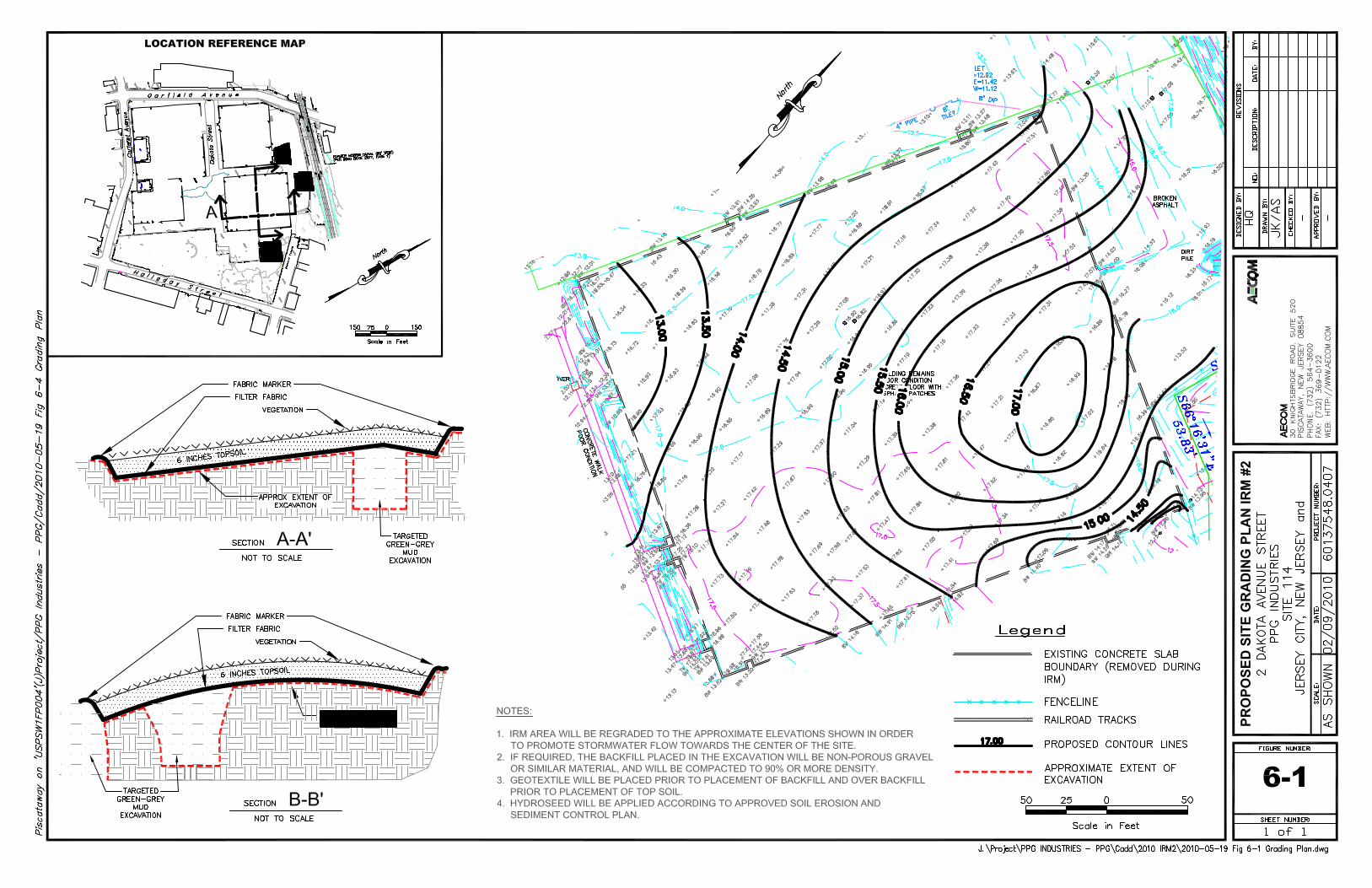
limits of the excavation. Materials may be stockpiled in the designated area as shown in Figure 3-2 if
direct loading is not practical. Figure 3-3 provides a detailed plan view of the IRM #2 Area that depicts
the anticipated excavation limits. Handling and disposal of debris is discussed in Section 8.
If required by the disposal facility, soil will be scraped or washed from the debris (metal, concrete, etc.),
as needed, using a high pressure washer within a bermed area to control runoff. Washed debris will be
stored in stockpiles, as needed. Soil removed from debris will be transferred from the bermed
containment area to a soil stockpile or drummed for disposal. Water used in the removal process will be
pumped from the bermed containment area, and transferred to on-site frac tanks for disposal. All waste
classification sampling, handling and disposal will be performed in accordance with Section 8 of this
work plan. All waste management activities will be documented in the final IRM Report. Once disposal
facilities have been selected, waste classification and sampling requirements for solids and liquids will
be determined and provided to NJDEP.
Based on available soil data, limited excavations to a maximum depth of 14 feet bgs is expected within
the northern portion of the IRM#2 Area, and excavation extending to approximately 20 feet bgs along
the western portion of the IRM#2 Area where the former Morris Canal is located is anticipated. The
excavation progress will be closely monitored by a remediation engineer or geologist.
While not expected, in the event a significant meadow mat layer (¾- to 1-foot thick, more than a 20 by
20 feet area) is encountered in the former Morris Canal location, excavation activities will be halted as to
AECOM Interim Remedial Measures WP#2 Environment
http://portal.env.aecomnet.com/projects/PPGChrome/GarfieldAve/WorkplansReports AECOM only/IRMWP-2/Final Submittal/2010_06_24 AdditionalComments/2010_07 FINAL IRMWP2_FD.docx July 2010
6-6
not disturb the meadow mat layer. When the meadow mat layer is encountered, the excavator operator
will be instructed to carefully peel back a small patch of the meadow mat with the excavator bucket
teeth. If the meadow mat is continuous (greater than 3/4- to 1-foot thickness), the excavator bucket will
be used to level off the disturbed area and no deeper excavation will occur in this area. Typically each
50-foot by 50-foot grid area will be tested. If the meadow mat layer does not exceed ¾- to 1-foot in
thickness, then the excavation will continue at that location until all apparent Green-Gray Mud is
excavated. Dewatering will be conducted to allow visual inspection of the excavation bottom.
Approximately 750 to 2,250 tons of Green-Gray Mud will be excavated during IRM mass removal
activities. Excavation limits will be surveyed following the completion of the excavation to document the
remediated areas. Receiving facility weight tickets will be used to document the quantity of soil
disposed. The objectives of the IRM#2 Area are presented below.
Excavation in the IRM#2 Area will continue until all Green-Gray Mud, concrete, utilities and debris are
removed. All other CCPW and other soil with concentrations above cleanup criteria will remain in place.
These remaining materials will be remediated as part of future remedial actions.
The following criteria and decision tree will be used to determine if Green-Gray Mud is present:
Sometimes paste-like material with a green or grey color (color is the primary criteria);
Material has a high pH (over 11);
Material effloresces when a drop of hydrochloric acid is applied (due to the presence of
calcium); and/or
Field screening indicates high (over 5,000 ppm) chromium levels.
AECOM Interim Remedial Measures WP#2 Environment
http://portal.env.aecomnet.com/projects/PPGChrome/GarfieldAve/WorkplansReports AECOM only/IRMWP-2/Final Submittal/2010_06_24 AdditionalComments/2010_07 FINAL IRMWP2_FD.docx July 2010
6-7
Decision Tree for IRMs 1 and 2 for Green Gray Mud (GGM) Determination
No
Fine grain material, (lessthan 200 microns)
Yes
What is the color?
See Limb 2
Lime Green orGray
Remove from Site
Indeterminate (not green or gray)
Apply Field Screening inthe following order.
XRF results greater than5,000 ppm total Cr? No
Leave on-site
pH above 11?Yes
Remove from Site
Does material efflorescewhen a drop of HCl is
applied? YesRemove from Site
Yes
No
No
Leave on-site.
Note: All GGM will be removed to the extentpractical. Where mixed material is present,GGM will be separated out or the blendedmaterial will be removed.
AECOM Interim Remedial Measures WP#2 Environment
http://portal.env.aecomnet.com/projects/PPGChrome/GarfieldAve/WorkplansReports AECOM only/IRMWP-2/Final Submittal/2010_06_24 AdditionalComments/2010_07 FINAL IRMWP2_FD.docx July 2010
6-8
Limb 2 of Decision Tree for IRMs 1 and 2 for Green Gray Mud (GGM) Determination
The site engineer will look for Green-Gray Mud as the building slab and other debris are removed. If
there is no surface evidence of Green-Gray Mud, test pits to 15 feet (or meadow mat) will be conducted.
The spacing of test pits will be determined by the site engineer but will not exceed a 50- by 50-foot grid
spacing.
No post-excavation sampling is proposed for the IRM#2 Area since source material (i.e., COPR) will
remain in place and will be subject to future soil remedial measures. Additionally, no laboratory analysis,
other than waste classification, will be performed. However, field characterization and sieving
technologies will be performed on test pit soils and the general field testing procedure for characterizing
them is summarized below.
The site engineer will establish 50 by 50 foot grids within the IRM#2 Area (Refer to Figure 6-2).
Samples from each grid will be collected in five gallon buckets. Typically three samples will be collected
from each grid (one sample from 0-5 feet bgs, one sample from 5-10 feet bgs and one sample from 10-
15 feet bgs).
Visual examination: Notes will be taken to document the presence or absence of COPR and
Green-Gray Mud based on visual inspection.
No
Fine grainmaterial, (less
than 200microns)
No
Is the material limegreen?
Is the material nativesoil? Leave on-site
Remove from Site
Yes
Yes
Leave on-siteNo
Note: All GGM will be removed tothe extent practical. Where mixedmaterial is present, GGM will beseparated out or the blendedmaterial will be removed.
AECOM Interim Remedial Measures WP#2 Environment
http://portal.env.aecomnet.com/projects/PPGChrome/GarfieldAve/WorkplansReports AECOM only/IRMWP-2/Final Submittal/2010_06_24 AdditionalComments/2010_07 FINAL IRMWP2_FD.docx July 2010
6-9
Field sieving: Soil will be physically screened on-site. Varying screen sizes will be used to
determine the relative proportions of soil in various size distribution ranges between 1 inch and
a No. 200 sieves. Prior to sieve analysis, soils will be weighed.
Field test for calcium: High levels of calcium (percent levels) would be expected in Green-
Gray Mud and possibly COPR. The XRF may provide an estimation of calcium content.
Testing with a drop of hydrochloric acid may also be used to assess the presence of calcium.
Field test for chromium: If reliable, screening with an XRF or other field instrument will be
conducted. This equipment can provide real-time measurements of total chromium in soil
samples. While XRF cannot distinguish between hexavalent and trivalent chromium, elevated
total chromium levels will provide an indication of the potential for higher levels of hexavalent
chromium in the sample and can be helpful as a tool to identify if COPR or Green-Gray Mud is
present.
Standard Operating Procedures for field characterization will be provided as an addendum to the FSP-
QAPP under separate cover.
6.12 Loading and Disposal
Excavated materials will be segregated according to visual observations and material type, and direct-
loaded into trucks for off-site hazardous disposal, or placed in stockpiles on-site for later classification
and removal. The overall waste management strategy is discussed in Section 8. Soil which is too wet
for immediate shipment will be placed in a dewatering area or dry cell within the excavation boundaries.
Any water draining from saturated soils will either drain into the excavation, or will be transferred via
pumps to on-site frac tanks pending disposal. Stabilizing agents will be utilized, if needed, prior to
loading for transport. On-site stabilization may be needed for off-site transportation of soil to meet the
paint filter test to avoid transport issues and to assure acceptance of the material at the designated
disposal facility. A paint filter apparatus will be set-up on-site. Potential absorbent materials and other
details will be identified in the Contractors Technical Execution Plan. Soil in stockpiles will be visually
observed and tested using the paint filter test. If a stockpile fails the paint filter test, the absorbent
material will be blended with the soil on-site using an excavator bucket or similar means.
The typical stockpile design is shown in the SESCP (Appendix H in IRMWP #1). All stockpiles will
include heavy duty plastic and tear resistant (fiber reinforced) bottom and top liners. All stockpiles will
include berms for containment of any water that drains from the soil. Stockpiles will be inspected at
least three times a day and repaired as needed. At the end of each shift, all piles will be securely
covered with a heavy duty plastic and tear resistant (fiber reinforced) liner and inspected. It is
anticipated that the Contractor will stockpile soil adjacent to the excavation within the IRM area. These
AECOM Interim Remedial Measures WP#2 Environment
http://portal.env.aecomnet.com/projects/PPGChrome/GarfieldAve/WorkplansReports AECOM only/IRMWP-2/Final Submittal/2010_06_24 AdditionalComments/2010_07 FINAL IRMWP2_FD.docx July 2010
6-10
temporary soil stockpiles within the work area will be within the IRM footprint and will be depleted
(removed) as the contractor progresses through the IRM excavation area. As the work progresses to
the full extent of the IRM excavation area, the temporary stockpile area outside the IRM area will be
used for both IRMs if needed.
Loading of excavated materials for disposal will be performed continuously during slab removal,
excavation and regrading activities. Trucks will be washed with a low pressure rinse and bed liners will
be installed in each truck upon entering the site. Wash water will be collected and routed to on-site frac
tanks for disposal. Trucks will then be carefully loaded in the designated loading area within the
exclusion zone. Truck operators will not be allowed to leave their vehicle upon entering the exclusion
zone. Once the trucks are filled, the liners will be closed by on-site personnel and each truck will be
inspected and decontaminated prior to leaving the exclusion zone. Prior to leaving the Site, each truck
will again be washed with a low pressure rinse to remove any remaining soil from the truck. Soil washed
from trucks and wash water will be collected in a truck washing area and routed to frac tanks or soil
stockpiles for disposal. Soil and water will be sampled and shipped as appropriately waste classified.
Applicable manifesting, licensing procedures, transportation requirements, and disposal requirements
under RCRA will be followed. Once a disposal facility is selected, additional information regarding
handling, loading and transportation of wet soils will be submitted to NJDEP, in order to demonstrate
how the methods used for saturated soil will meet regulatory and disposal facility requirements.
After slab removal, the contractor will likely deploy multiple teams working at the same time to reduce
the time required to complete the work. Each team will include an excavator, a front end loader,
operators and a site engineer to direct the Green-Gray Mud removal. Work in the IRM #2 Area is
estimated to take 15 to 30 working days.
6.13 Backfill and Grading
Only Green-Gray Mud and concrete will be excavated for off-site disposal during IRM#2, and all other fill
and CCPW will remain in-place. Following completion of the FS field testing and final technology
selection, remaining soil and groundwater impacts within the IRM Areas will be addressed under later
phases of remediation at Site 114. Accordingly, following removal of Green-Gray Mud, the IRM#2 Area
will be regraded using soil, fill, and CCPW remaining in the area.
No imported materials from an off-site source are anticipated for IRM#2 other than topsoil for use as
surface cover as described below. However, if additional off-site backfill (e.g., clean gravel) is required,
documentation will be submitted to NJDEP regarding the source and the physical properties of the
backfill and to confirm that the material is not contaminated. Any new backfill materials, including
AECOM Interim Remedial Measures WP#2 Environment
http://portal.env.aecomnet.com/projects/PPGChrome/GarfieldAve/WorkplansReports AECOM only/IRMWP-2/Final Submittal/2010_06_24 AdditionalComments/2010_07 FINAL IRMWP2_FD.docx July 2010
6-11
topsoil, brought onto the site will be certified clean in accordance with NJAC 7:26E-6.4(b)2. If needed,
Type II backfill will be used as agreed upon between PPG and the property owner/developers.
The entire IRM#2 Area will be completed by installing a permeable geotextile marker after regrading,
then a graded top soil cover, and hydroseeding. Certified clean topsoil will be imported to Site 114 for
temporary capping of the IRM#2 Area. To minimize run-off, the IRM#2 Area will be revegetated with
grass until subsequent remediation phases are conducted. The proposed surface finish is shown in
Figure 6-1.
6.14 Excavation Demobilization
Following completion of excavation and regrading activities, any dewatering sumps in the IRM area may
be deactivated and removed. Equipment will be decontaminated in designated areas. Any soil and/or
water produced during decontamination activities will be stored on-site in appropriate containers for
future disposal, or as otherwise described in Section 8. Water storage tanks will be decontaminated
following completion of all other decontamination activities and will be removed from the site, unless
maintained on-site for possible future use to support potential future IRM work or other future
remediation at the site. Sheet piling will be left in place for future remedial activities.
Stockpile containment areas will be demolished and removed from the site. Containment areas will be
decontaminated, dismantled and loose materials will be disposed of off-site. Wash water from the
containment areas will be pumped into on-site frac tanks for disposal following conclusion of IRM field
activities. Since stockpiles will be stored on layers of fiber reinforced liners located on either concrete or
asphalt impervious caps, subsurface soil sampling will not be necessary. Any soil observed on the
concrete or asphalt cap that originated from a stockpile will be removed via pressure washer and/or
vacuum and properly disposed. Following removal of soil stockpiles and decontamination of frac tanks,
any remaining materials (soil, debris, or water) will be contained on-site in 55-gallon drums pending
disposal or as otherwise described in Section 8.
Excavators, front end loaders, and any other on-site equipment utilized during excavation activities will
be decontaminated by high pressure water and/or steam prior to removal from the site. The tracking
pad, decontamination areas, and site trailer may remain in place for use during future remedial activities.
All soil, debris, and trash will be removed and disposed as described in Section 8. Any infrastructure
damaged on or off-site as a result of IRM activities will be returned to pre-existing conditions following
conclusion of field activities. Site features will be returned to pre-existing conditions following conclusion
of all IRM field activities.
AECOM Interim Remedial Measures WP#2 Environment
http://portal.env.aecomnet.com/projects/PPGChrome/GarfieldAve/WorkplansReports AECOM only/IRMWP-2/Final Submittal/2010_06_24 AdditionalComments/2010_07 FINAL IRMWP2_FD.docx July 2010
6-12
A survey of the IRM#2 area will be conducted at the conclusion of remedial activities to develop “as-
built” drawings as part of the IRM Report.
AECOM Interim Remedial Measures WP#2 Environment
http://portal.env.aecomnet.com/projects/PPGChrome/GarfieldAve/WorkplansReports AECOM only/IRMWP-2/Final Submittal/2010_06_24 AdditionalComments/2010_07 FINAL IRMWP2_FD.docx July 2010
7-1
7.0 Other Related Program and Project Documents
PPG has prepared several documents specifically related to the scope of work addressed in this Work
Plan and related to PPG’s overall Jersey City Chromium Remediation Program. These documents
include a Health and Safety Plan (HASP), a Field Sampling Plan / Quality Assurance Project Plan (FSP-
QAPP), an Air Monitoring Plan (AMP), a Dust Control Plan (DCP), a Traffic Safety and Control Plan
(TSCP), a Soil Erosion and Sediment Control Plan (SESCP), and a Stockpile Management Plan (SMP),
as discussed in the following sections.
7.1 Health and Safety Plan
A site specific HASP has been developed and was included as Appendix B in IRMWP #1. The
document presents program health and safety requirements and has been modified to specifically
address activities to be performed during both IRM and FS activities.
The HASP establishes health and safety procedures for activities to be conducted at the site. Once an
excavation contractor has been selected and final construction and health and safety specifications have
been determined, technical specifications and contractor health and safety information will be submitted
to NJDEP as an addendum. Requirements such as training program protocols, medical surveillance
program, equipment maintenance programs, personal hygiene practices, and other requirements of a
non-site specific nature are included in the HASP. The HASP has been and will continue to be updated
as needed to reflect new information, changes in site personnel, etc. Additional HASP(s) developed by
the excavation contractor for IRM field activities will be maintained on-site during construction and
forwarded to NJDEP.
7.2 Field Sampling-Quality Assurance Project Plan
The Field Sampling Plan / Quality Assurance Program Plan (FSP-QAPP) was submitted to NJDEP in
March 2006, and a revised version was submitted in February 2010. NJDEP provided comments to the
February 2010 FSP-QAPP and a subsequent version of the document is currently being developed.
The FSP-QAPP establishes the overall quality assurance objectives for the program, and documents the
sampling and analytical procedures to be used in collecting and analyzing samples. It also sets forth
procedures for equipment decontamination, sample handling, sample chain-of-custody, and other QA
procedures, which will be standard throughout the program.
AECOM Interim Remedial Measures WP#2 Environment
http://portal.env.aecomnet.com/projects/PPGChrome/GarfieldAve/WorkplansReports AECOM only/IRMWP-2/Final Submittal/2010_06_24 AdditionalComments/2010_07 FINAL IRMWP2_FD.docx July 2010
7-2
7.3 Air Monitoring and Control of Dust
In order to ensure that excavation and other intrusive activities do not pose an air quality hazard to off-
site areas, robust air monitoring and dust control programs will be implemented. The program will
consist of perimeter fenceline monitoring prior to commencement of field activities to establish baseline
conditions, and perimeter fenceline, exclusion zone, and personnel monitoring during the excavation.
The DCP and AMP were presented in Appendix C and Appendix D in IRMWP #1, respectively. Each
plan is described briefly below.
7.3.1 Air Monitoring Plan (AMP)
Eight air monitoring stations, four permanent and four mobile, will be set up around the perimeter of the
site and baseline air monitoring will be performed for five consecutive 24-hour periods preceding the
startup of planned IRM activities. The baseline air monitoring will be conducted not only to acquire
information about the site air quality prior to commencement of any site activities, but also to ensure that
all equipment is in proper working order and “debugged.” The background monitoring will consist of the
collection of real-time perimeter air quality data and integrated sampling for total dust and hexavalent
chromium (in dust). Integrated sampling for total dust and hexavalent chromium in dust will be
conducted at all air monitoring station locations.
Specific dedicated equipment at each station will include equipment for collecting continuous total
particulate readings, sampling ambient air for total dust and hexavalent chromium analysis, provide
programmable alarms to alert site personnel of exceedances, radio telemetry equipment to
communicate to on-site computers and pagers, and environmental enclosures to reduce the likelihood of
equipment damage from the elements. During IRM activities, continuous air quality monitoring and
sampling will be conducted 24 hours a day, 7 days a week. During onsite remedial activity periods, daily
and weekly reporting protocols will be established by the site managers with guidance from NJDEP and
PPG. These weekly reports will be produced in electronic and/or hard copy formats (including potential
web updates) to be determined by PPG with guidance from NJDEP. Reports depicting a summary of
the air monitoring results will be provided on a minimum of a monthly basis. A summary of all air
monitoring and sampling data, including weather station and daily wind rose data, will be provided as
indicated in the AMP.
During intrusive site activities, the air monitoring program will include operation of perimeter fenceline
stations, and ongoing monitoring in the work/exclusion zone via mobile units and portable handheld units
for worker protection. Work/exclusion zone air monitoring procedures are presented in the site specific
HASP (Appendix B in IRMWP #1). Air monitoring during site activities will occur for the duration of the
site work. A detailed AMP was presented as Appendix D in IRMWP #1.
AECOM Interim Remedial Measures WP#2 Environment
http://portal.env.aecomnet.com/projects/PPGChrome/GarfieldAve/WorkplansReports AECOM only/IRMWP-2/Final Submittal/2010_06_24 AdditionalComments/2010_07 FINAL IRMWP2_FD.docx July 2010
7-3
7.3.2 Dust Control Plan (DCP)
As most of the intrusive activities will occur below the water table, dusty conditions are not expected.
However, initial surface excavation work, breaking up of concrete foundations, soil loading, regrading,
truck travel on-site, and the stockpiling of soils have the potential to generate dust. A site specific DCP
has been developed for the IRM activities (Appendix C in IRMWP #1) and includes the following:
Listing of potential dust sources from on-site activities (DCP Section 2);
Explanation of goals for the Dust Control Plan (DCP Section 3);
Description of equipment used for air/dust monitoring perimeter fenceline, exclusion zone, and
personal monitoring within the exclusion zone (DCP Section 4);
Identification of proactive and responsive controls implemented for dust suppression (DCP
Section 5);
Dust control application protocols for the excavation area, on-site transportation routes, and
stockpiles (DCP Section 6); and
Dedicated dust control personnel will be in charge of inspecting all activities, directing any dust
suppression activities, monitor air monitoring/sampling equipment, and applying dust
suppression agents (DCP Section 7).
7.4 Traffic Safety and Control Plan
A TSCP has been prepared for the IRM and FS field work to assist in traffic control, and motorist and
community safety during the IRM trucking activities, and to facilitate early discussion with stakeholders
regarding the potential impact of IRM activities on local traffic and the community. In addition,
emergency responders will be informed and consulted regarding the location of the truck routes and
safety measures described in this plan. The TSCP may be updated as necessary and also used for
future remedial activities at the Site. The TSCP is included as Appendix E in IRMWP #1.
The purpose of the TSCP plan is to provide a description of protocols to assist in traffic control and
safety during IRM activities at the Site. The TSCP includes specific information about truck travel
routes, truck operator certifications, and perimeter road signage associated with activities at and around
the Site during IRM activities. Included in the TSCP are sections describing truck safety measures,
travel routes and tracking, truck operator requirements, and recordkeeping procedures.
AECOM Interim Remedial Measures WP#2 Environment
http://portal.env.aecomnet.com/projects/PPGChrome/GarfieldAve/WorkplansReports AECOM only/IRMWP-2/Final Submittal/2010_06_24 AdditionalComments/2010_07 FINAL IRMWP2_FD.docx July 2010
7-4
7.5 Soil Erosion and Sediment Control Plan (SESCP)
The Site is relatively flat and is developed with asphalt, concrete, and/or processed gravel and poses no
special concerns for the SESCP. The SESCP erosion control measures will be implemented prior to
intrusive activities and will include measures such as hay bales, sediment fences, storm sewer inlet
protection, equipment tracking pad, equipment decontamination pad and wash water collection system.
In addition, should material unintentionally be deposited on paved surfaces on or off-site, surfaces will
be vacuumed and/or pressure washed to remove potential for direct contact. Daily inspections of
roadways and sidewalks surrounding the site will be performed to ensure any spilled material is cleaned
up expediently. Wash water will be collected and stored in on-site frac tanks for later disposal. The total
area of disturbance is greater than one-half acre; therefore, a SESCP approval permit is required and
has been approved by the Soil Conservation District and is provided in Appendix H of IRMWP #1.
7.6 Stockpile Management Plan
A Stockpile Management Plan (SMP) has been prepared for this field work to assist in segregating
concrete for disposal and meet the requirements of respective disposal facilities. The concrete will be
segregated into concrete and demolition (C&D) waste, non-hazardous contaminated concrete waste,
and hazardous waste. The SMP was provided as Appendix F in IRMWP#1.
AECOM Interim Remedial Measures WP#2 Environment
http://portal.env.aecomnet.com/projects/PPGChrome/GarfieldAve/WorkplansReports AECOM only/IRMWP-2/Final Submittal/2010_06_24 AdditionalComments/2010_07 FINAL IRMWP2_FD.docx July 2010
8-1
8.0 Waste Management Procedures
This section describes the material handling procedures to be followed during excavation activities
associated with this phase of the IRM. Specifically this section describes the procedures for the
evaluation, handling, testing (if applicable) and final disposition of the soil, debris, waste material and
groundwater that may be encountered during these activities.
Construction activities associated with this phase of the IRM#2 will include excavation with potential
dewatering and off-site disposal of soil and other materials. Green-Gray Mud excavated from the IRM#2
area will be classified as hazardous and disposed in appropriately permitted facilities.
8.1 Excavated Material Management
For the area to be excavated, the primary contaminant of concern will be chromium, and other metals.
Low levels of volatile organics (VOCs) have also been detected in the IRM area. Visual examination of
excavated soil and screening of the excavation limits with a photoionization detector (PID) will be
conducted. Should any PID readings around the excavation limits be observed above 100 ppm or if
obvious MGP odors are detected by on-site personnel, the soil will be screened using a PID. If MGP
waste is encountered and odor control is required, foam may be employed and applied directly to the
soils. Stockpile covers will also reduce the potential for MGP waste odor issues, if encountered. If soil
screening reveals PID readings above 100 ppm, the soil in question will be segregated within the
temporary soil stockpile area (shown in Figure 3-2), headspace readings collected, and soil samples
collected for laboratory analysis in accordance with disposal facility requirements.
Disposal facility sampling requirements will be forwarded to NJDEP determined based on the selection
of facilities prior to the commencement of IRM activities. The following procedures will be implemented
as part of the excavation process:
The management of excavated materials will be conducted in such a manner as to prevent the
spread of contamination and/or contaminated materials. All work must be performed in
accordance with the approved Soil Erosion and Sediment Control Plan (SESCP).
Soils and concrete/debris material will be stockpiled on the 880 Garfield Avenue slab, in the
areas designated as temporary stockpile area in the Figure 3-2.
AECOM Interim Remedial Measures WP#2 Environment
http://portal.env.aecomnet.com/projects/PPGChrome/GarfieldAve/WorkplansReports AECOM only/IRMWP-2/Final Submittal/2010_06_24 AdditionalComments/2010_07 FINAL IRMWP2_FD.docx July 2010
8-2
Visually impacted chromium contaminated materials (i.e. Green-Gray Mud) will be stockpiled
separately from materials not showing visual impacts.
Soils with visual or olfactory evidence of petroleum contamination or with PID readings greater
than 100 ppm will be segregated separately for further analysis.
Concrete/debris will be stockpiled separately as required by the disposal facilities. Excess soils
will be shaken or scraped from concrete/debris to the reasonable extent possible prior to
stockpiling.
Detailed records of sampling activities and laboratory analyses will be maintained.
Sampling procedures will conform to the most recent guidance in NJAC 7:26E Technical
Requirements for Site Remediation and the NJDEP Field Sampling Procedures Manual.
All wastes generated during the field operations at the Site will be handled as generally detailed in the
NJDEP Guidance Document for the Remediation of Contaminated Soils (1998), and the most current
FS-QAPP and disposed of off-site as either non-hazardous or hazardous waste. Wastes that will be
generated include excavated soils, concrete and debris, contaminated clothing, decontamination fluids,
purge water, dewatering liquids, and general garbage. Solids such as well abandonment cuttings and
decontamination solids will be containerized in United States Department of Transportation (USDOT)
approved 55-gallon drums or stockpiled for disposal off-site. All drums will be stored on-site in the
stockpile area shown on Figure 3-2. Waste characterization sampling will be performed as required by
the disposal facility.
Excavated materials will be staged in the designated stockpile area, as depicted on Figure 3-2.
Dewatering fluids will be pumped directly into frac tanks for off-site disposal as non-hazardous
contaminated waste or as hazardous waste. Stockpiles of saturated soils will allow water to drain,
collected in frac tanks, and disposed off-site. All waste will be transported in compliance with regulatory
and the disposal facility’s requirements.
8.2 Stockpile Sampling and Waste Classification
The following discussion applies to segregated materials that are stockpiled during construction
activities. The following procedures will also be used to determine the appropriate option for the ultimate
off-site disposal of each material.
AECOM Interim Remedial Measures WP#2 Environment
http://portal.env.aecomnet.com/projects/PPGChrome/GarfieldAve/WorkplansReports AECOM only/IRMWP-2/Final Submittal/2010_06_24 AdditionalComments/2010_07 FINAL IRMWP2_FD.docx July 2010
8-3
8.2.1 Soil Stockpile Sampling
If required by disposal facilities, soil will be characterized in place prior to excavation or samples will be
collected from soil stockpiles. Sampling frequency and parameters will be determined by the receiving
facility. Sampling of stockpiled material, as required, will be conducted in general accordance with
Section V.C.2.a (4) of the NJDEP Guidance Document for the Remediation of Contaminated Soils
(1998), or as required by disposal facilities. Any deviation from the guidance documents will be
documented and addressed with NJDEP. It is anticipated that the majority of excavated material will be
shipped and disposed of as hazardous waste. Therefore, a relatively small sampling frequency may be
used and all the soil will be assumed to contain elevated levels of chromium dependent upon disposal
facility selection. Soils not exhibiting visual impacts will be segregated and stockpiled separately for
waste classification and off-site disposal.
8.2.2 Concrete and Debris Stockpile Sampling
Stockpiling of concrete and debris (e.g. rebar and underground utilities) is not anticipated, unless
required by disposal facilities, during IRM activities. Concrete that is visibly contaminated (e.g., green in
color) will be assumed hazardous and segregated from other concrete not exhibiting visual impacts. All
other concrete that is not visually assumed hazardous will be classified for offsite disposal. Where
possible, direct loading for offsite waste disposal will be considered when in-situ waste classification
sampling is performed and waste profile acceptance is received prior to exhuming the waste.
To the extent possible, concrete and debris will be demolished inside the IRM excavation limits and live
loaded into lined disposal trucks. Concrete or debris that does not show visual impairment will be
stockpiled for waste classification. Concrete and debris sampling and analysis will also be performed in
general accordance with the NJDEP Guidance Document for the Remediation of Contaminated Soils, or
as required by the disposal facilities. If a stockpile is needed for debris, it will be constructed in the same
area as the soil stockpile south of the IRM excavation area as depicted in Figure 3-2. No concrete will
be sent off-site for recycling.
8.3 Off-Site Disposal
All materials excavated during this phase of the IRM will be handled, transported and disposed of as
non-hazardous contaminated waste or hazardous waste dependent upon waste classification sampling.
Waste characterization sampling will be performed as required by the disposal facilities. Details
regarding waste classification sampling requirements will be determined based on the disposal facilities
selected. Details regarding sampling requirements by disposal facilities, if any, will be submitted to
NJDEP in an addendum when details have been determined with the disposal facilities. Transportation
AECOM Interim Remedial Measures WP#2 Environment
http://portal.env.aecomnet.com/projects/PPGChrome/GarfieldAve/WorkplansReports AECOM only/IRMWP-2/Final Submittal/2010_06_24 AdditionalComments/2010_07 FINAL IRMWP2_FD.docx July 2010
8-4
and disposal of all materials will be in accordance with applicable disposal facility requirements and
federal, state, and local regulations. The appropriate transport documentation will be completed before
any materials are removed from the Site. Transport and disposal documentation will be included in an
IRM report submitted to NJDEP following completion of IRM activities.
8.4 Stormwater and Stockpile Management
As necessary, all stockpiles will be placed on a minimum of one layer of 20-mil polyethylene sheeting or
similar heavy duty plastic and tear resistant (fiber reinforced) liner. Separate stockpiles for soil,
concrete, and/debris will be limited in size and located south of the IRM excavation area as shown in
Figure 3-2. The stockpiles will be securely covered with a tear resistant, fiber reinforced liner during
inclement weather and when soils are not actively being added or removed from the stockpile. A water
spray will be utilized for dust suppression and foam will be utilized for stabilization of stockpiles, if
necessary. The containment area will be maintained for the duration of the staging period in order to
prevent runoff from contaminated soil, leaching of contaminants into runoff water and fugitive dust
emissions. Any stockpiles which may receive saturated soil will be equipped with diversionary structures
in order to contain and collect all water which may drain from the soils. Stormwater which enters any
active excavation or stockpile location will be collected and containerized for disposal as needed.
Detailed information regarding stockpiles is provided in the SMP (Appendix F in IRMWP #1).
AECOM Interim Remedial Measures WP#2 Environment
http://portal.env.aecomnet.com/projects/PPGChrome/GarfieldAve/WorkplansReports AECOM only/IRMWP-2/Final Submittal/2010_06_24 AdditionalComments/2010_07 FINAL IRMWP2_FD.docx July 2010
9-1
9.0 Community Relations during IRM Activities
PPG will work with the Site Administrator (SA) under the JCO to conduct public relations with community
stakeholders regarding Site 114 in compliance with N.J.A.C. 7:26E-1.4(a), and to address the
Department's recent Public Outreach Guidance. The SA is responsible for maintaining regular
communications with community representatives to solicit their opinions and ideas and communicate
community concerns to the partnership. PPG continues to coordinate closely with the NJDEP's Office of
Community Relations, and has provided numerous fact sheets and other documentation related to
ongoing and future public relation efforts. The SA will continue to host public meetings and coordinate
additional public outreach to keep the communities apprised of plans and progress. During execution of
the IRM, AECOM will assist PPG and the SA in these efforts by providing frequent detailed updates of
the status of field activities, remedial objectives, goals, and schedule.
In the event of an incident with off-site impact, PPG will supplement Jersey City’s municipal emergency
communications plan with telephone calls and e-mails to a list of community contacts the company has
developed. The list includes elected officials as well as the leaders from area block associations and
non-profit organizations. Additionally, the members of this list have been provided with telephone
numbers and e-mail addresses for contacting the SA or the company’s community relations consultants,
24 hours a day, seven days a week. In conjunction with the SA, the company will also develop fact
sheets for distribution and use at its community information center at the Garfield Avenue
Redevelopment Corporation office, located approximately eight blocks from the site and in the heart of
the neighborhood’s business district.
PPG’s community information center is staffed Tuesdays and Thursdays, from 10 a.m. to 2 p.m. Also,
interested parties can schedule appointments with the SA to coordinate discussions with the company’s
community relations consultants. The center contains a map of Jersey City that lists all sites for which
PPG is responsible, including those that have received a No Further Action (NFA) approval. The center
also serves as a repository for documents filed with the NJDEP and contains binders with the latest filing
for each site. A meeting room in the rear of the center is made available to community groups in the
neighborhood.
AECOM Interim Remedial Measures WP#2 Environment
http://portal.env.aecomnet.com/projects/PPGChrome/GarfieldAve/WorkplansReports AECOM only/IRMWP-2/Final Submittal/2010_06_24 AdditionalComments/2010_07 FINAL IRMWP2_FD.docx July 2010
10-1
10.0 Schedule and Reporting
Upon completion of NJDEP review and approval of this IRMWP, PPG will select the contractor to
complete the remedial activities. Following contractor selection, technical specifications, contractor
operational plans, HASPs, and other relevant documentation will be submitted to NJDEP. Excavation
activities are expected to begin within 100 days of receipt of NJDEP approval of IRMWP #2. A
preliminary draft schedule is provided as Figure 10-1. The following are major milestones and
estimated completion timeframes for the proposed activities:
Acquisition/Approval of Local Building/Construction Permits will be performed under IRMWP #1.
One application will be submitted to cover all IRM and FS activities. (Ongoing)
Slab Removal/Excavation (November 2010).
IRM#2 Draft Interim Remedial Action Report (IRAR) Submittal to NJDEP for Review and
Approval (Estimated to be submitted in March 2011).
AECOM will submit the IRM#2 IRAR to NJDEP summarizing the overall performance of IRM#2
implemented at the Site. The report will include:
Summary of previous investigations;
Description of IRM#2 activities completed;
“As-built” survey drawings showing the extent of excavation(s);
Description of site restoration activities; and
Remedial action costs incurred to date.
The overall performance of the remedial measures, excavation and shoring, water management, waste
management, dewatering data, laboratory documentation, and air monitoring data will also be
summarized and/or included in the report. Supporting tables and figures will be included with the report
detailing the IRM treatment areas, volume of impacted soil removed, and sampling results. Fully
executed manifests and weight tickets documenting off-site disposal will be included in an appendix.
AECOM Interim Remedial Measures WP#1 Environment
http://portal.env.aecomnet.com/projects/PPGChrome/GarfieldAve/WorkplansReports AECOM only/IRMWP-2/Final Submittal/2010_06_24 AdditionalComments/2010_07 FINAL IRMWP2_FD.docx July 2010
11-1
11.0 References
AECOM, 2010, Field Sampling Plan-Quality Assurance Field Sampling Plan / Quality Assurance ProjectPlan Non-Residential Chromium Sites, Hudson County, New Jersey.
Drake, A.A., Jr., Volkert, R.A., Monteverde, D.H., Herman, G.C., Houghton, H.F., Parker, R.A., andDalton, R.F., 1996. Bedrock geologic map of northern New Jersey, US Geological Survey,Miscellaneous Investigations Series, I-2540-A, 1:100,000.
ENSR, 2006. Remedial Investigation Report, PPG Site 114 – Garfield Avenue, Jersey City, New Jersey.
ENSR, 2006. Off-Site Remedial Investigation Workplan, Site 114 – Garfield Avenue, Jersey City, NewJersey.
ENSR, 2006. Field Sampling Plan / Quality Assurance Program Plan.
ENSR, 2005. Health and Safety Plan, On-Going Remedial Investigations, Non-Residential Site 114,Garfield Avenue, Jersey City, New Jersey.
New Jersey Department of Environmental Protection (NJDEP), November 2009. AdministrativeRequirements for the Remediation of Contaminated Sites (ARRCS), N.J.A.C. 7:26C et. seq., adoptedNovember 4, 2009, last amended April, 19, 2010.
NJDEP, August 2005. Field Sampling Procedures Manual.
NJDEP, November 2009. Groundwater Quality Standards (N.J.A.C. 7:9C), last amended November 4,2009.
NJDEP, January 1998. Guidance Document for the Remediation of Contaminated Soils.
NJDEP, November 2009. Remediation Standards, N.J.A.C. 7:26D et. seq., last amended November 4,2009.
NJDEP, July 5, 2005. Technical Requirements for Site Remediation, N.J.A.C. 7:26E et. seq., lastamended April 19, 2010.
NJDEP, September 2008. Chromium Soil Cleanup Criteria, last revised April 20, 2010.
NJDEP, February 2007. NJDEP Commissioner Jackson’s February 8, 2007 Memorandum RegardingChromium Moratorium.
NJDEP. Letter to W. Michael McCabe. 5 May 2010. Comments on March 2010 Draft Interim RemedialMeasures Work Plan #2; 2 Dakota Street – PPG Site 114; Jersey City, New Jersey.
NJDEP, Soil Cleanup Criteria, last revised May 1999.
AECOM Interim Remedial Measures WP#1 Environment
http://portal.env.aecomnet.com/projects/PPGChrome/GarfieldAve/WorkplansReports AECOM only/IRMWP-2/Final Submittal/2010_06_24 AdditionalComments/2010_07 FINAL IRMWP2_FD.docx July 2010
11-2
SECOR, 2008. Column Study Report, Former PPG Garfield Facility.
USEPA, In Situ Treatment of Soil and Groundwater Contaminated with Chromium, October, 2000.
USGS, 1967, Photorevised 1981, Jersey City-NJ-NY Jersey City Quadrangle. 7.5 Minute Series.Topographic Map (Northeastern Quadrant-Latitude: 4037.5N Longitude: 7400 W).
USGS, 1898, Staten Island-New Jersey Quadrangle. 15 Minute Series. Topographic Map (NortheasternQuadrant-Latitude: 40.6250 N Longitude: 74.125 W).
AECOM Interim Remedial Measures WP#2 Environment
http://portal.env.aecomnet.com/projects/PPGChrome/GarfieldAve/WorkplansReports AECOM only/IRMWP-2/Final Submittal/2010_06_24 AdditionalComments/2010_07 FINAL IRMWP2_FD.docx July 2010
Cr - Total chromiumCr+6 - Hexavalent chromiumEh - laboratory based oxidation reduction potentialpH - pH standard unitsCOPR - Chromate Chemical Production WasteNA - Not applicableSPLP - Synthetic Precipitation Leaching Procedure
Field Exam - Visual and sieve analysis for percent COPR and presence of Green-Gray MudRCRA 8 - 8 RCRA metalsTCLP - Toxicity Characteristics Leaching Procedure (TCLP)TCLVOC - TCL Volatile organicsTCLSVOC - TCL Semi-volatile organicsTALMetals - Target Analyte List MetalsPCB - Polychlorinated biphenylsTOC - Total Organic CarbonRCRA - RCRA Characteristics of Ignitability, Corrosivity and Cyanide/Sulfide ReactivityTPH - Total Petroleum Hydrocarbons
## - Sample number to be determined
In-Situ Treatment
Waste Classification for All Remedial Activities
QA Samples for All Remedial Activities
5 Waste classification samples will be generally analyzed at a frequency of 1 composite per 500 tons. Field sample frequency and/or sample parameters will bedependent upon disposal facility selection.
4 The number of waste classification samples will vary dependent upon the total quantity and type of waste generated for offsite disposal. A1 = Stockpile designationwhich varies. YY = Last two digits of the year; MM = month; DD = day.
2 Soils will be visually logged (test pit profiling, physical screening for screen size, visual screening for percent COPR) and field screened with a Photoionization Detector(PID) for VOCs . Other field screening may include: 1) XRF screening for metals, and/or 2) calcium field screening with hydrochloric acid. 10% of samples will beanalyzed for Cr+6, Eh, pH, TAL metals, VOC, and SVOC.
1 Sample depth for excavation bottom will be field selected.
3 Refer to Section 7.2 of Feasibility Study (Additional Data for Groundwater and Saturated Soil Treatment) .
http://portal.env.aecomnet.com/projects/PPGChrome/GarfieldAve/WorkplansReports AECOM only/IRMWP-2/Final Submittal/2010_06_24 AdditionalComments/2010_07 FINAL IRMWP2_FD.docx July 2010
1 Interim Remedial Measures at Site 114 (IRM2) - Slab Removal / Excavation 20.1 mo Fri 10/30/09 Tue 6/7/112 Permits (under IRM#1) 5.25 mo Mon 11/30/09 Thu 4/29/103 IRM#2 - 2 Dakota Slab removal and excavation 20.1 mo Fri 10/30/09 Tue 6/7/114 IRM#2 Work Plan 7.75 mo Fri 10/30/09 Fri 6/11/105 IRM#2 - Implementation 13.1 mo Fri 5/21/10 Tue 6/7/116 Remedial action 8.85 mo Fri 5/21/10 Fri 2/4/117 Finalize Bid Specification and Contractor Selection 1.5 mo Fri 5/21/10 Fri 7/2/108 Slab Removal/Excavation 3.25 mo Mon 11/1/10 Fri 2/4/119 Air Monitoring/Oversight 3 mo Mon 11/1/10 Fri 1/28/11
10 Soil Excavation, stockpiling, T&D 2.5 mo Mon 11/1/10 Thu 1/13/1111 Site Restoration (grading, topsoil, seed) 3 mo Mon 11/8/10 Fri 2/4/1112 Interim Remedial Action Report (IRAR) #2 5.5 mo Thu 12/30/10 Tue 6/7/1113 Draft IRAR preparation 1.5 mo Thu 12/30/10 Fri 2/11/1114 PPG Presentation/Overview Meeting Summarizing Future Submittal 0.25 mo Mon 2/7/11 Fri 2/11/1115 JCO Team Feedback to PPG from presentation 0.25 mo Mon 2/14/11 Fri 2/18/1116 PPG Finalize Draft Submittal to SA, NJDEP, JC, Developer/Owner 1 mo Tue 2/22/11 Mon 3/21/1117 SA provide Report to TC 0 days Mon 3/21/11 Mon 3/21/1118 JC Review and Submit Comments to NJDEP, TC, SA, PPG 0.5 mo Tue 3/22/11 Mon 4/4/1119 Developer/Owner Review and Submit Comments to NJDEP, TC, SA, PPG 1 mo Tue 3/22/11 Mon 4/18/1120 TC Review and Submit Comments/Recommendations to NJDEP 1.25 mo Tue 3/22/11 Mon 4/25/1121 NJDEP Review and Comments to PPG and SA 0.5 mo Tue 4/26/11 Mon 5/9/1122 PPG Revisions and Resubmittal 0.25 mo Tue 5/10/11 Mon 5/16/1123 NJDEP Review 0.25 mo Tue 5/17/11 Mon 5/23/1124 NJDEP Final and/or Conditional Approval 0 days Mon 5/23/11 Mon 5/23/1125 PPG Finalize Submittal 0.5 mo Tue 5/24/11 Tue 6/7/11