* * CE SCIENCES 9 . ’ FINAL REPORT INCORPORATED 301 BEAR HILL ROAD. WALTHAM. MASS. DEVELOPMENT OF A CONTINUOUSLY OPERATING SOURCE OF VACUUM ULTRAVIOLET AND SOFT X-RADIATION Contract NAS 5-39 10 . 653 July 65 Prepared By Space Sciences Inc. 30 1 Bear Hill Road Waltham Massachusetts Goddard Space Flight Center Greenbelt, Maryland https://ntrs.nasa.gov/search.jsp?R=19660017586 2018-06-22T14:57:48+00:00Z
Transcript
*
*
CE SCIENCES
9 .
’ FINAL REPORT
INCORPORATED
301 BEAR HILL ROAD. WALTHAM. MASS.
DEVELOPMENT OF A CONTINUOUSLY OPERATING SOURCE O F VACUUM
DEVELOPMENT OF A CONTINUOUSLY OPERATING SOURCE O F VACUUM
ULTRAVIOLET AND SOFT X-RADIATION
Contract NAS 5-3910
Prepared BY
Space Sciences Inc. 30 1 Bear Hill Road
Waltham Massachusetts
Goddard Space Flight Center Greenbelt, Maryland
i
ABSTRACT
This final report describes the research and development of an intense vacuum ultraviolet and soft X-radiation source which provides line radiation et wavelengths less than 500 Angstroms. The method developed utilizes a vacuum arc where the arc is confined within a magnetic mirror field (Duo Plasma- tron Type Source). With this source bright line spectra of Helium f Bod Helium I1 have been obtained.
This report contalns a summary of pertinent activities during the development program. The design of the instrumen- tation which is to be delivered to NASA is reviewed.
CONTENTS
ABSTRACT
TABLE OF CONTENTS
TABLE OF FIGURES
1. Introduction
2 . Background and Feasibility
2 . 1
2.2
2 .3
2 . 4 Experimental Considerations
The Energetic Arc of Luce
The Magnetic Mirror of Alexeff The Duo Plasmatron of Von Ardenne
2 . 4 . 1
2.4.2 Line Radiation Bremsstrahlung Radiation
3 . The Experimental Apparatus
3 . 1
3.2 The Grazing Incidence Spectrometer
3.3 The Duo Plasmatron Source
3.4 The Electronic Chassis
The Vacuum System
4 . Results and Conclusions.
ii
i
ii
iii
1
3
4
5
7
9 9
11
14
14
14
18
22
29
LIST OF REFERENCES
iil
Number
FIGURES
T i t l e
1
- 2
3
4
5
6
7
8
9
10
11
1 2
13
14
15
16
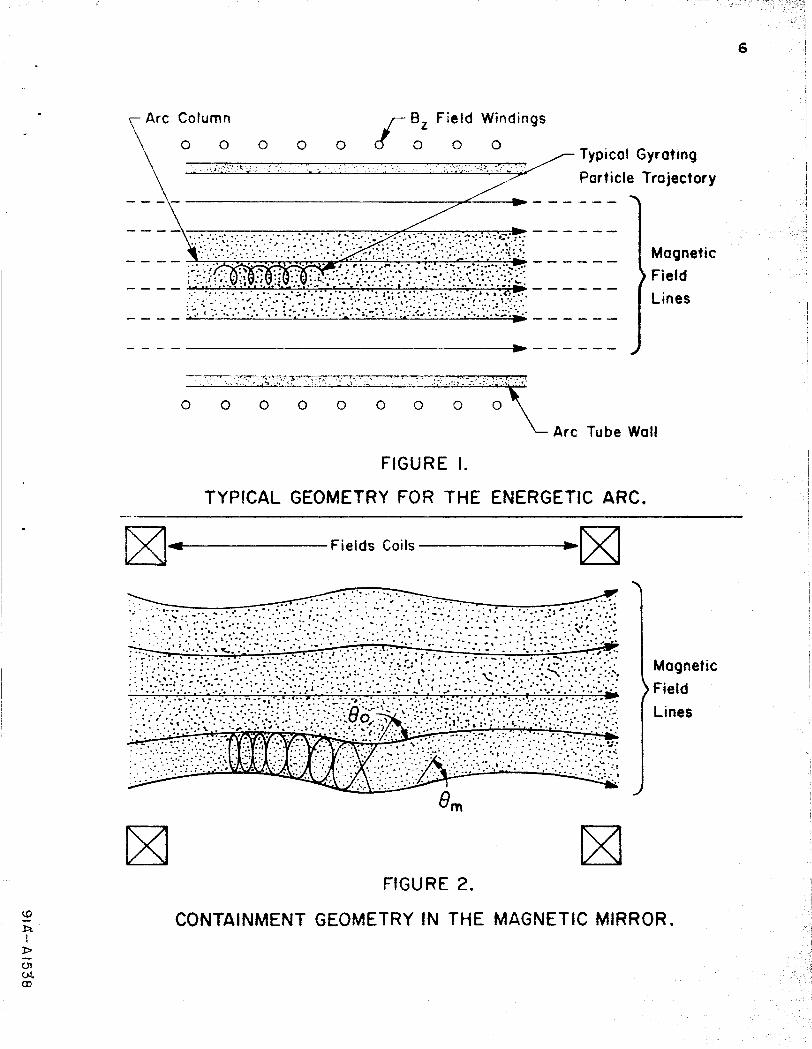
Typical Geometry for the Energetic Arc.
Containment Geometry in the Magnetic Mirror.
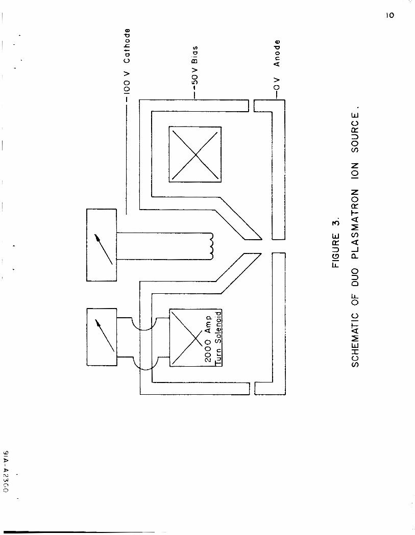
Schematic of Duo Plasmatron Ion Source.
Bremsstrahlung Radiation for kT = 30 ev.
The Experimental System.
The Fiducial Marker System.
The Duo Pla smatron Type Source.
Magnetic Field Measurement in the Duo Plasmatron
Type Source.
Schematic of Anode Electrode.
The Duo Plasmatron Source and System Electronics.
General Wiring Diagram.
Current Regulated Arc Power Supply.
The Filament Supply Circuit.
The Magnet Supply Circuit.
Typical Vacuum Ultraviolet Helium Spectra
Spectrometer Calibration.
e
Page
G
6
10
12
15
16
17
20
2 1
23
25
26
27
28
30
3 1
1
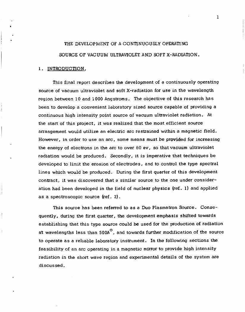
THE DEVELOPMENT OF A CONTINUOUSLY OPERATING
SOURCE OF VACUUM ULTRAVIOLET AND SOFT X-RADIATION.
1 . INTRODUCTION.
Th i s final report describes the development of a continuously operating
source of vacuum ultraviolet and soft X-radiation for u s e in the wavelength
region between 10 and 1000 Angstroms. The objective of this research has
been to develop a convenient laboratory sized source capable of providing a
continuous high intensity point source of vacuum ultraviolet radiation. A t
the start of this project, it was realized that the m o s t efficient source
arrangement would uti l ize an electric arc restrained within a magnetic field.
However, in order to u s e an a rc , some means must be provided for increasing
the energy of electrons in the arc to over 60 ev , so that vacuum ultraviolet
radiation would be produced. Secondly, it is imperative that techniques be
developed to l i m i t the erosion of electrodes, and to control the type spectral
l ines which would be produced. During the first quarter of th i s development
contract , it was discovered that a similar source to the one under consider-
ation had been developed in the field of nuclear physics (ref. 1) and applied
as a spectroscopic source (ref. 2).
This source has been referred to as a Duo Plasmatron Source. Conse-
quently, during the first quarter, the development emphasis shifted towards
establishing that th i s type source could be used for the production of radiation
at wavelengths less than 500A0, and towards further modification of the source
to operate as a reliable laboratory instrument. In the following sections the
feasibility of a n arc operating in a magnetic mirror to provide high intensity
radiation in the short wave region and experimental detai ls of the system are
d iscussed .
2
In Section 2 , background and feasibility are discussed. Here, the
natural evolution of ideas which has culminated
Plasmatron source are reviewed. As an adjunct to th i s , the conditions for
producing vacuum ultraviolet radiation a re analyzed as they apply to the
Duo Plasmatron source. In Section 3 , a complete description of the exper-
imental system is given. Section 4 , shows typical spectal resul ts which
have been obtained using Helium gas in the Duo Plasmatron type source.
A discussion of resul ts and experimental problems is also included here.
with the u s e of a Duo
3
2. RRcr<aour .JD AND FFASIBILITY
The Space Sciences' approach to the physical design for the arc source
has evolved as a natural summation of two techniques which have been reported
in the literature. These techniques include an energetic vacuum arc, and the
compression of a n electron beam induced discharge by means of a magnetic
mirror. The merger of these two techniques is the Duo Plasmatron technique,
and it is shown in the following sections that this technique will provide the
solar spectroscopist with a strong continuously operating source of radiation
spanning the soft x-ray region.
The energetic arc, studied extensively by Luce (Reference 3) and reviewed
briefly in the next section , has shown remarkable efficiency in producing cop-
ious vacuum ultraviolet radiation. Measurements have indicated that a s much
as 50% of the input arc power appears as radiation below about 1200 A . The
input power in this instance was about 30 kilowatts and the arc was 6 fee t i n
length. Clearly, the arc in this form is unsuitable as a feasible and flexible
laboratory source. However, the arc and its power requirements can be scaled
down to values more reasonable for the application to a laboratory vacuum ultra-
violet source. The energetic arc column employed by Luce was constrained by
means of an axial magnetic field between widely separated electrodes.
0
By shaping the magnetic field so that it closes at the ends, the flow of
current can be restricted, and power conserved. One such application has been
reported by klexeff (Reference 4). Alexeff has observed the radiation charac-
ter is t ics from a weak plasma generated i n a mirror field by means of an energetic
electron beam. This study demonstrates s o m e of the techniques for effective
plasma trapping in the mirror field. However, in Alexeff's work , the charge
carrier density was not high, and consequently, the radiation rate was lower
than that reported by Luce.
4
2 .1 The Enerqetic Arc of Luce.
The energetic a rcs which have been s tudied , range i n arc column length
from 6 inches to 6 feet. For arc currents of 250 amp, the arc voltage drop was
120 v for the 6-foot a r c , and 55 v for the 12-inch arc . With the configuration
employed the 12-inch arc was operated at currents down to 50 amp (i.e., at a
power level of 2 .5 kilowatts, approximately). The energy radiated by a 1 -foot
section of the 6-foot arc operating at a power level of 30 kilowatts (SKW/ft) was
determined by a calorimetric technique. The resul ts indicated between 2 .5 and
3 K W of radiant power suggesting a radiation effkiency.of more than 50%. More-
oyer;; m&st of this radiation was determined to lie in the vacuum ultraviolet
spectrum below 1200OA. Experiments show that the ion and electron tempera-
tures are comparable numerically to t h e a rc drop voltage, i.e. k T % k T % 50
t o 100 electron volts. The ion-electron density in the a rc plasma was deter-
mined to lie in the range of 1013 to 10
e i
14 -3 c m . In the energetic vacuum arc, a large current is passed between two
electrodes in vacuum. By passing a large current through the system, the
surface of the a rc electrodes is volatalized. It is the molecules from the
electrodes which ionize and migrate between electrodes constituting the
current. This is a "bootstrap" effect where the flow of current is usually
limited by an external circuit resistor. Obviously, t he current flow must be
great enough to supply the charge carriers by volatalization.
Although the current density must be high at the electrodes, the charge
carriers will normally diffuse from t h e axis of the arc. In the Luce arc, a
solenoidal field is used to restrict th i s radial migration. In the proposal of
t h i s contract, Document Number SSI-P-91A, it was shown that t h i s magnetic
restriction is beneficial i n increasing t h e electron-ion density (n) i n the arc
column (Refs. 3-8). It was shown that i n this arc n = n = 10 c m and - - 14 -3 i e
5
2 that the power radiated in the Bremsstrahlung continuum is proportional t o n
according to the equation
3 -21 3 2 - 1.9 x 10 z n exp (- 1*24 lo4) erg/cm sec A
e I/ 2 XkT 8 ( k T ) e p1 -
- 14 -3 5 3 With n = 10 c m , the total Bremsstrahlung yield is about 10 ergs/cm sec.
In addition there is a bright line spectrum where power radiated is described
by the proportionality
3 P2 = n 0 v g f exp (-E/kT)
and it was estimated that individual spectrum lines may account for as much 8 3 as 10 ergs/cm sec.
These radiation levels are desirable for a useable laboratory source
but the power requirements are not satisfactory for spectroscopic instrumenta-
tion. One way t o l i m i t the power in the arc is to shape the magnetic field
so as to restrict t h e flow of current except very close to the tube axis. In the
energetic vacuum arc the magnetic confinement is two dimensional (Figure 1).
A method to conserve more power involves enhanced magnetic Confinement
as shown i n the next section.
2.2 The Magnetic Mirror of Alexeff
11 -3 In the technique of Alexeff, the electron densi ty was only 10 cm ,
3 3 the radiated power density 10 ergs/cm sec and the input power approximately
2.5 kilowatts. Although the radiation levels are not a s desirable as those used
by Luce , the power requirements are obviously more applicable . Again, as s h m n
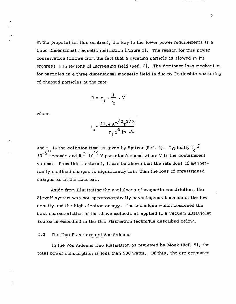
in the proposal for this contract, the key to the lower power requirements is a
three dimensional magnetic restriction (Figure 2). The reason for th i s power
conservation follows from the fact that a gyrating particle is slowed in its
progress into regions of increasing field (Ref. 5). The dominant loss mechanism
for particles in a three dimensional magnetic field is due to Coulombic scattering
of charged particles a t t h e rate
. v 1 i t
R = n . - C
where
11.4 A '/ 2T3/ 4 t =
C ni z In A
- and t is t h e collision t i m e a s given by Spitzer (Ref . 5). Typically t =
-5 10
volume. From th is treatment, it can be shown that the rate loss of magnet-
ica l ly confined charges is significantly less than the loss of unrestrained
charges as in the Luce arc.
C - C seconds and R = lo1' V par.-ticles/second where V is the containment
Aside from illustrating the usefulness of magnetic constriction, the
Alexeff system was not spectroscopically advantageous because of the low
densi ty and the high electron energy. The technique which combines the
b e s t characterist ics of the above methods as applied to a vacuum ultraviolet
source is embodied in the Duo Plasmatron technique described below.
2 . 3 The Duo Plasmatron of Von Ardenne
In the Von Ardenne Duo Plasmatron as reviewed by Moak (Ref . 9 ) , t he
total power consumption is l e s s than 500 watts. Of th i s , the a rc consumes
8
150 wat t s , the magnetic field requires 250 watts, and the filament used to
initiate the arc requires 70 watts. Typical arc voltage drops are 70 volts,
and typical arc currents are 2 amps. In this mode of operation, the separa-
tion between electrodes is less than one inch. The energy radiated from this
plasma has not been determined, however line spectra have been shown by
Samson (Ref. 2) in the range between 1500 and 500 8. The remainder of the
spectral parameters still need to be determined.
14 -3 In the Duo Plasmatron, ion densities as high as 10 c m have been
reported, a value similar to that reported for t he energetic arc in spite of the
lower power consumption. In addition , the entire source assembly requires
a volume of only 100 in . 3
Although the general characteristics of th i s source have been reviewed,
very little description has been given regarding the operation of the Duo
Plasmatron source. The original source was designed by Von Ardenne and
named by him. The source was designed to deliver proton currents of the
order of an ampere. Several of these sources have been built and it appears
they operate well in accelerator applications.
There are two design concepts which are bas ic to a Duo Plasmatron
source . 1. The bas ic discharge is a three-electrode arrangement. The electrode
placed between the cathode and anode has a small aperture which
restricts the arc.
2. To the basic discharge is added a magnetic mirror field in the s m a l l
region of high ion density. As mentioned earlier, th is mirror field
acts t o reflect the electrons so that escape is possible only very near
the axis. The arc is thus caused to draw down to a very s m a l l conical
envelope coming t o a point a the anode. It is E the point of t h 14 3
t ip where ion densit ies of 6 x 10 ions/cm occur.
9
arc-
This s y s t e m is shown diagramatically in Figure 3. In this design, the
electrodes serve simultaneously as magnetic pole pieces , eliminating the need
for a relatively ineffective air cored solenoid. Here the magnetic field can be
concentrated across two electrodes where the spacing and diameter is Smal l ,
thereby increasing the system efficiency. In addition, the voltage of the
middle electrode and the magnetic field can be altered , which changes the
total energy across the arc.
2.4 Experimental Considerations
It has been pointed out that th i s source is capable of producing both a
bright line spectra, and a continua due to bremsstrahlung radiation. I t is
interesting t o note the conditions for producing each of these types of radia-
t ion in the Duo Plasmatron type source.
2.4.1 Bremsstrahlunq Radiation
In Section 2 . 1 , it was shown that when monoenergetic electrons lose
energy by free-free interactions , the bremsstrahlung radiation is emitted.
The total power radiated for a transparent plasma, expressed in terms of
power per unit wavelength interval is
1 . 9 0 ~ 1 0 -21 Z 3 n 2 exp (- 1.24 lo4 ) 2 1/ 2 X kT,
ergs
c m s e c A " 3 PA = We)
where Z is t h e effective atomic number, kT, is the electron temperature in
electron volts , and n is the electron density in electrons per c m and whereX 3
l -
Q) rn 0 r 0 V
> 0 0 I
c
-
a 0 0 c a > 0
lL 0 3 n
IO
11
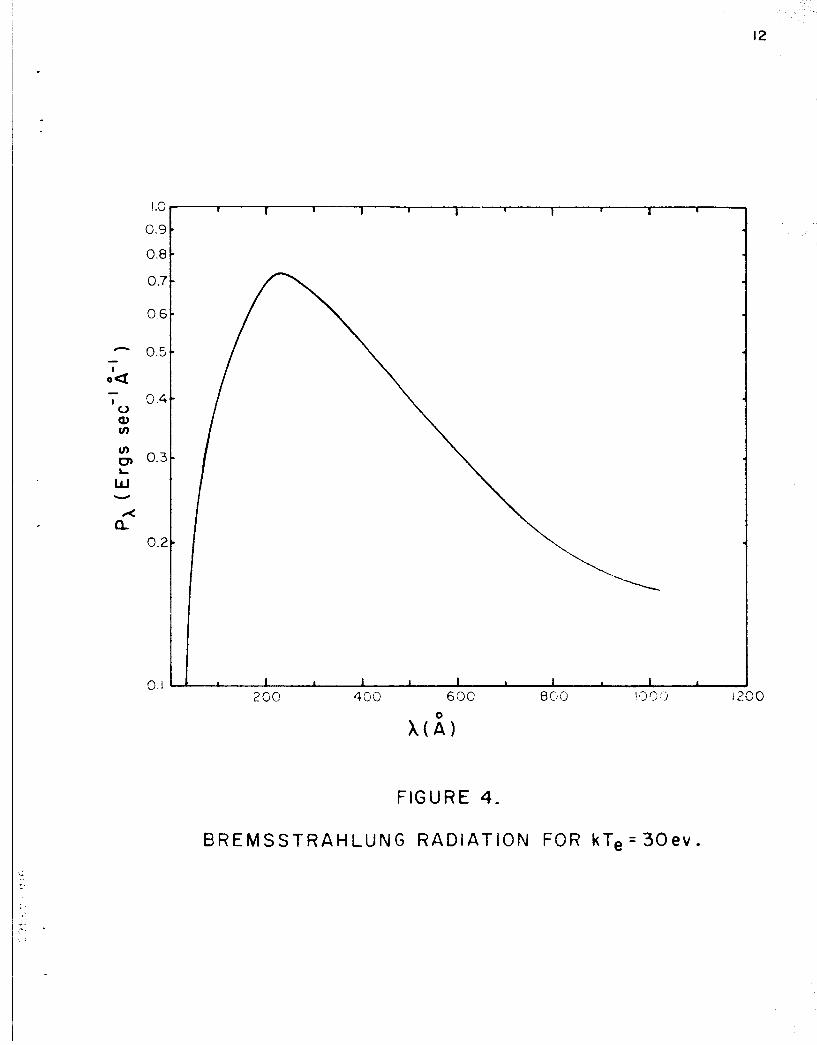
is in Angstroms. The spectrum has a maximum at
3 0 h (kT ) = 6.2 x 10 (A ev) m e (3)
Under ordinary source operating conditions , the filament is 150 volts negative
with respect t o the anode, while 30-40 volts may be measured between the grid
and anode , (a dis tance of .025 "). It has been reported 14 3 the a r c t ip ion densi t ies of 6 x 10 ions/ c m occur. The bremsstrahlung
radiation may be computed from equations (2) and (3) . For th i s calculation
Z = 4(He), and kT = 30 ev. This equation gives thepowerperunitvolume and
the actual radiating volume has been estimated at .001 c m . The results are
shown in Figure 4 from which it can be seen that bremsstrahlung radiation ac-
counts for energy levels of about 1 / 2 erg sec
probably less than our scattered light background, and has not been detected
by us . In order t o be ab le t o detect bremsstrahlung radiation a n interesting
possibil i ty is to increase the Z number of the gas used. For instance the use
of Argon instead of Helium might increase the bremsstrahlung radiation yield
1000 t i m e s .
that at the point of
3 e
-1 -8 or 5 x 10 watts. This is
2.4.2 Line Radiation
In our Duo Plasmatron type source, a voltage difference of 30 volts
exists across the a r c gap, but a few electrons are accelerated from cathode
potential (-150 volts) to the anode at ground potential. Those electrons
which are accelerated without collision will have an energy up to 150 volts.
Any l ines with excitation potential less than 30 ev will be excited by the
Duo Plasmatron source assuming that the energy is not great enough for
complete ionization t o exist. By adjusting the system pressure and the cur-
rent transported by the a rc the case of total ionization can be avoided.
I P 0.
0.
0 .
0
0.
9.
0.
0.
1 I I I 1 I I I I I
0.. 200
12
400 600
FIGURE 4.
B R E M S S T R A H L U N G R A D I A T I O N FOR kT, = 3 0 e v .
13
Unlike the case for bremsstrahlung radiation, the prediction of l ine
intensit ies is extremely difficult. It is more feasible to experimentally
evaluate line intensity. The theoretical l ine intensity is given by the
proportionality
(4 1 3 I - n 0 y gf exp (-E/kT)
where n is the number density of atoms in the ground state, g is the de-
generacy of the upper energy state at the energy level E and f is the
transition probability. Uncertainty in f-values and in n impose severe
limitations in accuracy in carrying out prediction calculations.
0
0
The gas which has been used for l ine investigation is ilelium. In the
vacuum ultravoilet region Helium I is excited at potentials less than 24.4 volts
and Helium I1 is excited at potentials less than 53.8 volts.
From the source characterist ics, it is apparent that He I l ines should
be produced by the arc. For He I1 to be produced by the a rc , excitation must
be produced by electrons which are emitted from the cathode, and which
collide between t h e bias and anode electrodes.
have been detected.
Both types of spectral l ines
14
3. TriE EXPERIMENTAL APPARATUS
The apparatus which has been used for the experimental portion of the
development program cons is t s of four distinct parts, i. e . , a vacuum system,
a one half meter grazing incidence spectrometer, a Duo Plasmatron Source,
and the source electronics. The important features of each of these com-
ponents will be described in the following text .' 3.1 The Vacuum System.
The vacuum system used is of conventional design, incorporating a
valve system which permits protection of the hot diffusion pump oil. The
system combines a 140 l i ter /minute Welch Duo Seal Pump and an NRC air
cooled oil diffusion pump with a speed of 285 liters/second at 10-6Torr. The
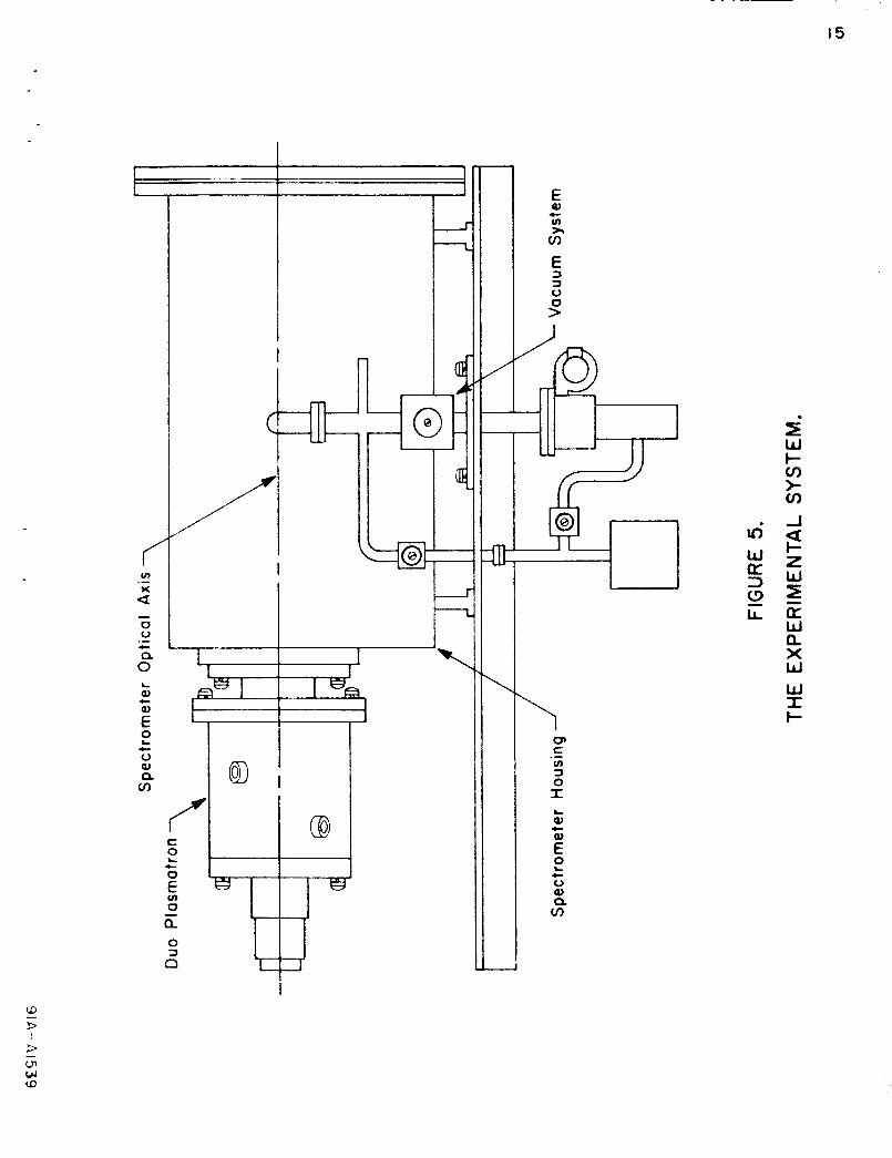
s y s t e m is capable of a base pressure of approximately 1 0-6mm Hg . The vacuum system is connected directly to a chamber which houses
the grazing incidence spectrometer. The entrance slit of the grazing inci-
dence spectrometer fits against a port in the vacuum chamber. The Duo
Plasmatron source is mounted to the outside of this vacuum chamber and
oriented so that the point source of radiation is along the optical axis of the
vacuum ultraviolet spectrometer. This system is illustrated in Figure 5.
G a s is injected into the vacuum system through the Duo Plasmatron
source.
and it is this gas which supports the arc during operation.
3 . 2 The Grazing Incidence Spectrometer.
The gas which is injected is the gas whose spectra is to be detectea,
The Grazing Incidence Spectrometer is the same spectrometer which has
been used under contract NAS 5-3365. It is a 1/2 meter grazing incidence
type , with a grating density of 576 lines/mm and a n 88 0 angle of ihcidence.
Two changes have been made from the standard spectrometer during
the past development program. First, scattered light h a s been reduced.
E 0)
v) ZI
c
v, E 3 3 0
P
\
\ v c u) 13 0 I
0,
W
.-
L
c
E 2 c 0 Q, a. v,
16
, 11’ F i l m P lane
/-- ,- R u b b e r
FIGURE 6.
THE FIDUCIAL MARKER SYSTEM.
Mold
..
. ight Bulb
\
Gas
Viewin Port
FIGURE 7. THE DUO PLASMATRON TYPE OPTICAL SOURCE.
de
.
18
A l l non-critical parts have been black anodized in order to prevent multiply
reflected light from reaching the Kodak SWR Film. In addition, extra baffles
have been added a t the interface between the spectrometer and vacuum chamber.
The second change which has been made comprises a reconstruction of the f i l m
holder. A new f i lm holder was made because it was found that the first holder
did not provide sufficient accuracy in adhering to the Rowland Circle. The new
holder has a 50 centimeter radius of curvature, and conforms to the Rowland
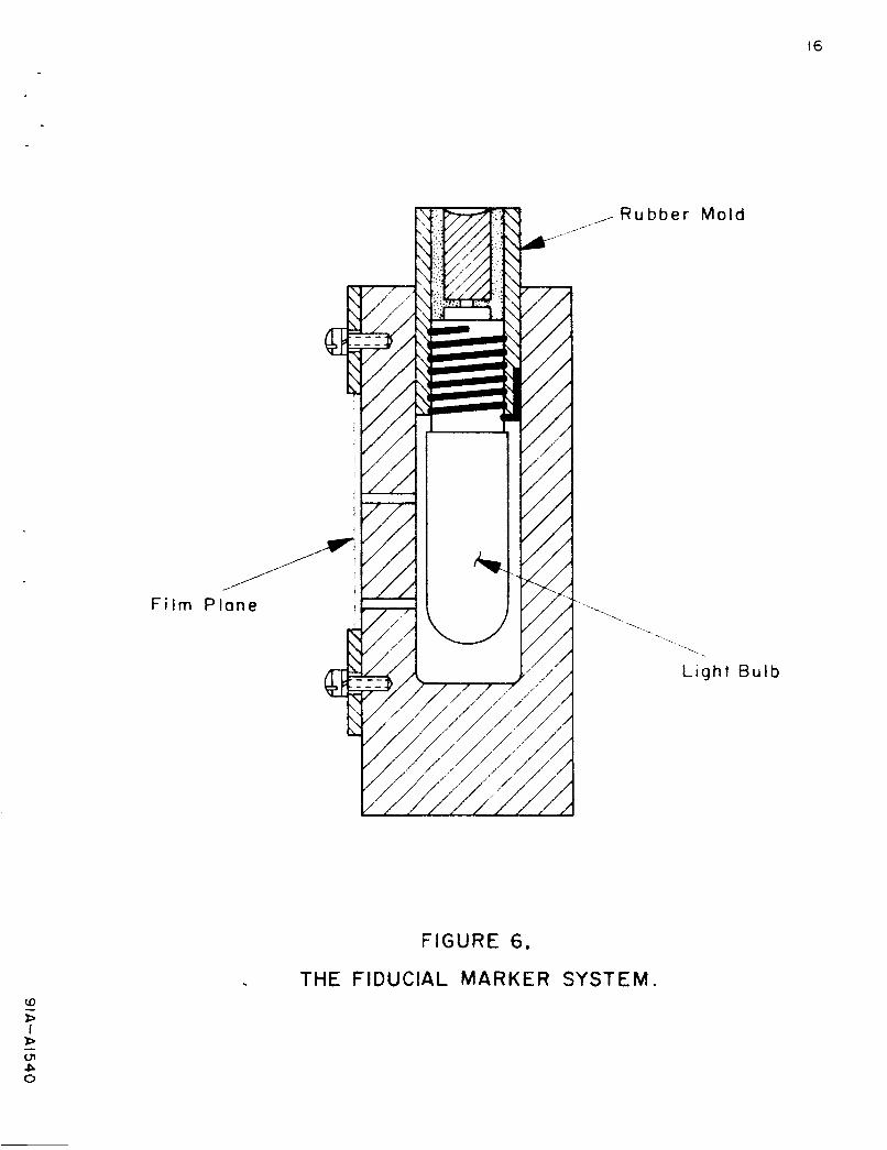
Circle with a deviation less than +.OOS c m . In addition, a simple fiducial
marker arrangement has been added in order to facilitate the superimposing of
various spectra. This fiducial marker arrangement was found exceptionally
useful since it also provided a constant exposure reference i n order to check
the f i lm development process. The fiducial marker consis ts of two s m a l l holes
( . 0 13 ") i n the f i l m holder , perpendicular to the position of the f i l m . A s m a l l
light bulb is positioned behind the two holes and shielded so as not to scatter
light onto other portions of the fi lm . This system is demonstrated i n figure 6
The light is activated in the darkroom after the spectrometer has been removed
from the vacuum chamber. In this arrangement, one bulb electrode is connected
to the spectrometer internally and the other is positioned on top of the fiducial
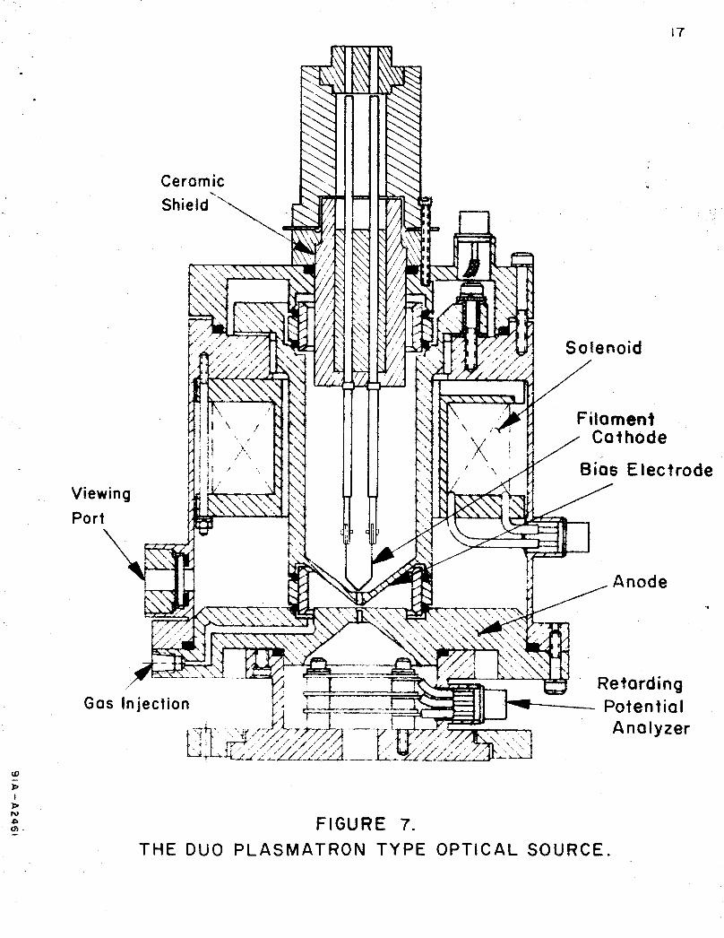
marker as se mbly . 3 . 3 The Duo Plasmatron Source .
The Duo Plasmatron Source which has been developed during the develop-
ment program is shown schematically in Figure 7. In order to assist the
understanding of this source, reference to Figure 3 should be made.
The components which consitute the magnetic circuit are composed of
soft iron. These components include the anode, the bias electrode, and that
portion of the outer chamber which is between these two electrodes. The sole-
noid used for producing the magnetic field is supplied by 1000 turns of number
18 copper wire. The nose cone of the bias electrode is that portion of the
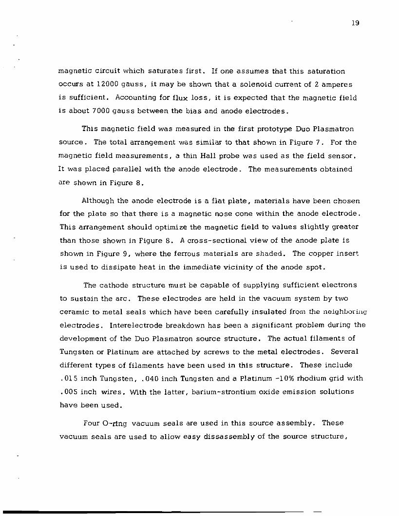
19
magnetic circuit which saturates first. If one assumes that this saturation
occurs at 12000 gauss , it may be shown that a solenoid current of 2 amperes
is sufficient. Accounting for flux loss, it is expected that the magnetic field
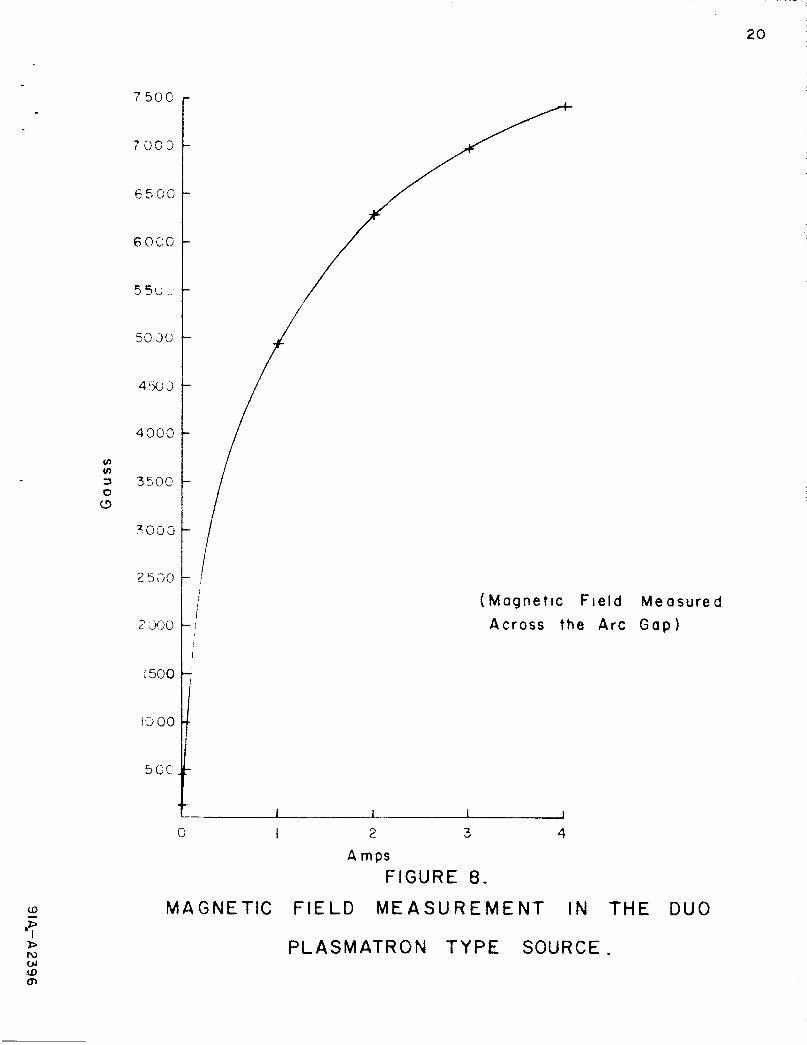
is about 7000 gauss between the bias and anode electrodes.
This magnetic field was measured in the first prototype Duo Plasmatron
source. The total arrangement was similar to that shown in Figure 7 . For the
magnetic field measurements, a thin Hall probe was used as the field sensor.
It was placed parallel with the anode electrode. The measurements obtained
are shown in Figure 8.
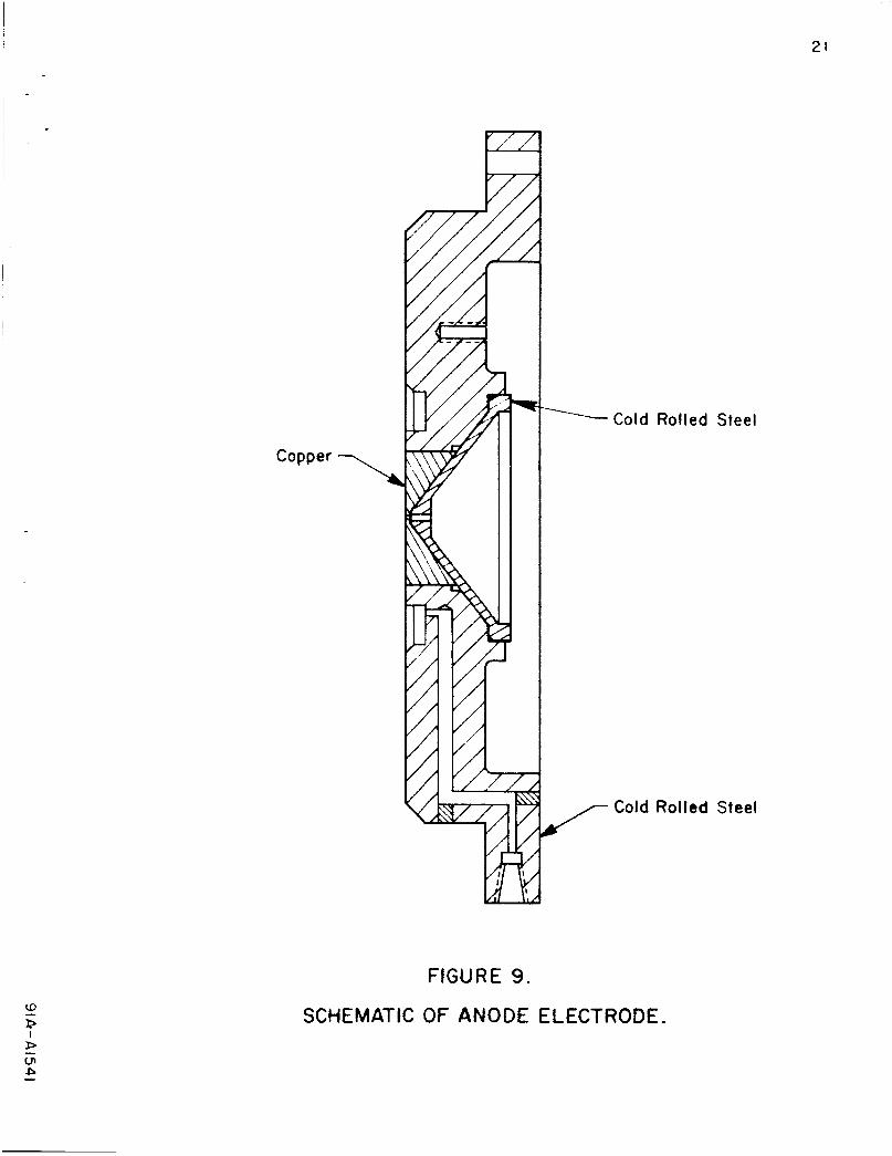
Although the anode electrode is a flat plate, materials have been chosen
for the plate so that there is a magnetic nose cone within the anode electrode.
This arrangement should optimize the magnetic field to values slightly greater
than those shown in Figure 8. A cross-sectional view of the anode plate is
shown in Figure 9 , where the ferrous materials are shaded. The copper insert
is used to dissipate heat in the immediate vicinity of the anode spot.
The cathode structure must be capable of supplying sufficient electrons
to sustain the arc. These electrodes are held in the vacuum system by two
ceramic to metal seals which have been carefully insulated from the neighborins
electrodes. Interelectrode breakdown has been a significant problem during the
development of the Duo Plasmatron source structure. The actual filaments of
Tungsten or Platinum are attached by screws to the m e t a l electrodes. Several
different types of filaments have been used in this structure. These include
.015 inch Tungsten, .040 inch Tungsten and a Platinum -10% rhodium grid with
.005 inch wires. With the latter, barium-strontium oxide e m i s s i o n solutions
have been used.
Four O-ring vacuuni seals are used i n this source assembly. These
vacuum sea l s are used to allow easy dissassembly of the source structure,
7 50Ci
6 0 0 0
4 W 3
4300
ln
250 '3
2 xx
! 500
IO 00
5 G C .
I
( M a g n e t i c F i e l d M e a s u r e d A c r o s s t h e A r c G a p )
0 I 2 3 4
A mps FIGURE 8.
MAGNETIC FIELD M E A S U R E M E N T I N THE DUO
P L A S M A I R O N TYPE SOURCE.
21
Copper -7
CD B i
FIGURE 9.
-------Cold Rolled Steel
/ Cold Rolled Steel
SCHEMATIC OF ANODE ELECTRODE,
should dissassembly be required. These seals are employed at the interfaces
between the various electrodes. The O-rings are positioned between the outer
surface of a glass tube and a polished metal groove. A Plexiglas ring is used
to force the O-ring against both the polished metal ring and the glass cylinder.
Each Plexiglas ring is used for two O-ring seals.
The glass to metal seals are cooled by circulating oil. This cooling is
essent ia l since 1 KW is dissipated in the source region.
A t f irst Freon 113 was used a s the coolant, but it was found difficult to
use because of vapor formation once the. circulating pump became warm. For
this reason, insulating oil was selected a s the final choice in coolants.
Besides providing the required cooling facilities, this oil also acts as a n
insulation preventing breakdown outside the vacuum between the bias and anode
electrodes. It is particularly useful where the iztterelectrode spacing is close.
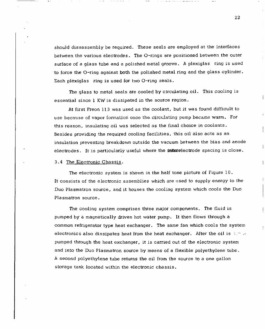
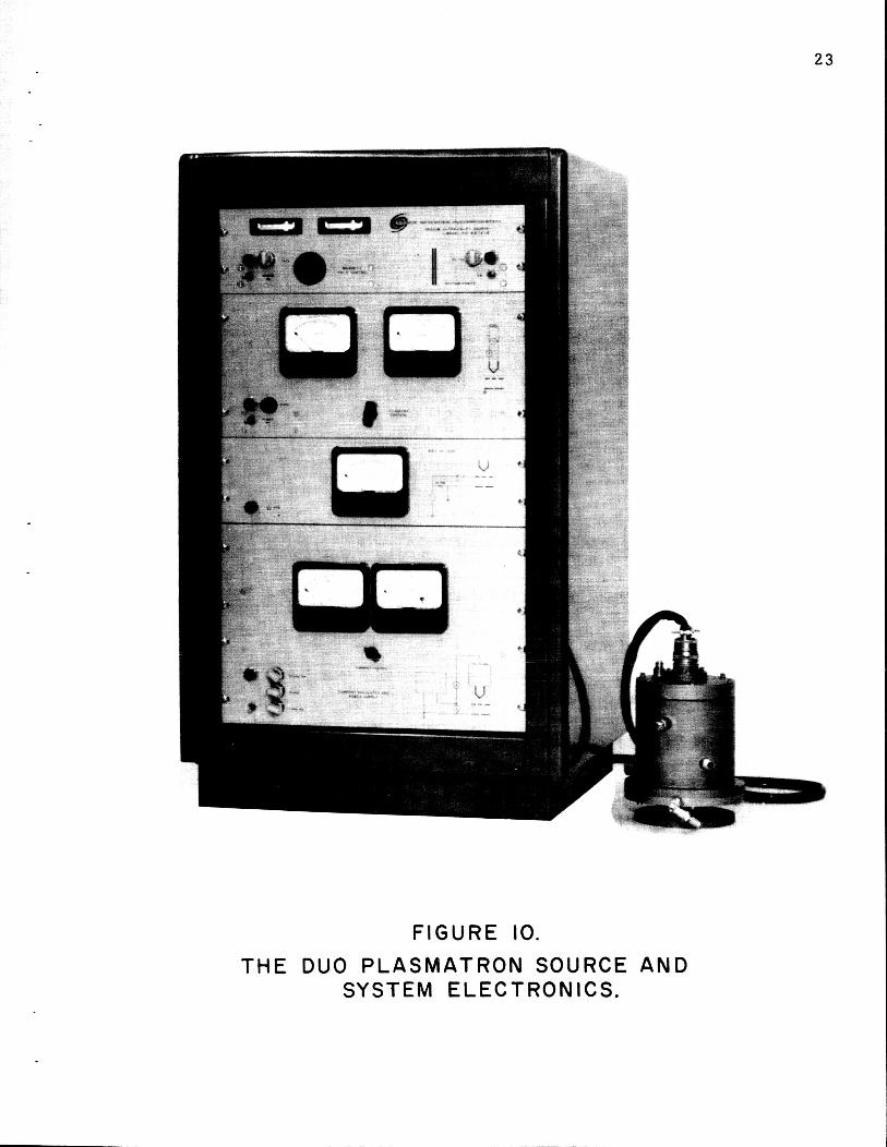
3 . 4 The Electronic Chass i s .
Th-e eiectronic system is shown in the half tone picture of Figure 1 0 .
It cons is t s of the electronic assemblies which are iised to supply energy to the
Duo Plasmatron source, and it houses the cooling system which cools the Duo
Pla smatron source.
The cooling system comprises three major components, The fluid is
pumped by a magnetically driven hot water pump. It then flows through a
common refrigerator type heat exchanger. The same fan which cools the system
electronics also diss ipates heat from the heat exchanger. After the oil is .::- - a .
pumped through the heat exchanger, it is carried out of the electronic system
and into the Duo Plasmatron source by means of a flexible polyethylene tube.
A second polyethylene tube returns the oil from the source to a one gallon
storage tank located within the electronic chass i s .
23
F I G U R E IO.
SYSTEM E L E C T R O N I C S . T H E DUO P L A S M A T R O N SOURCE A N D
24
It was found necessary to place the heat exchanger after the circulating
pump since the pump itself was found to heat up the circulating oil. By this
re-positioning of the heat exchanger, the greatest ratio of output temperature
to input temperature of the oil could be obtained.
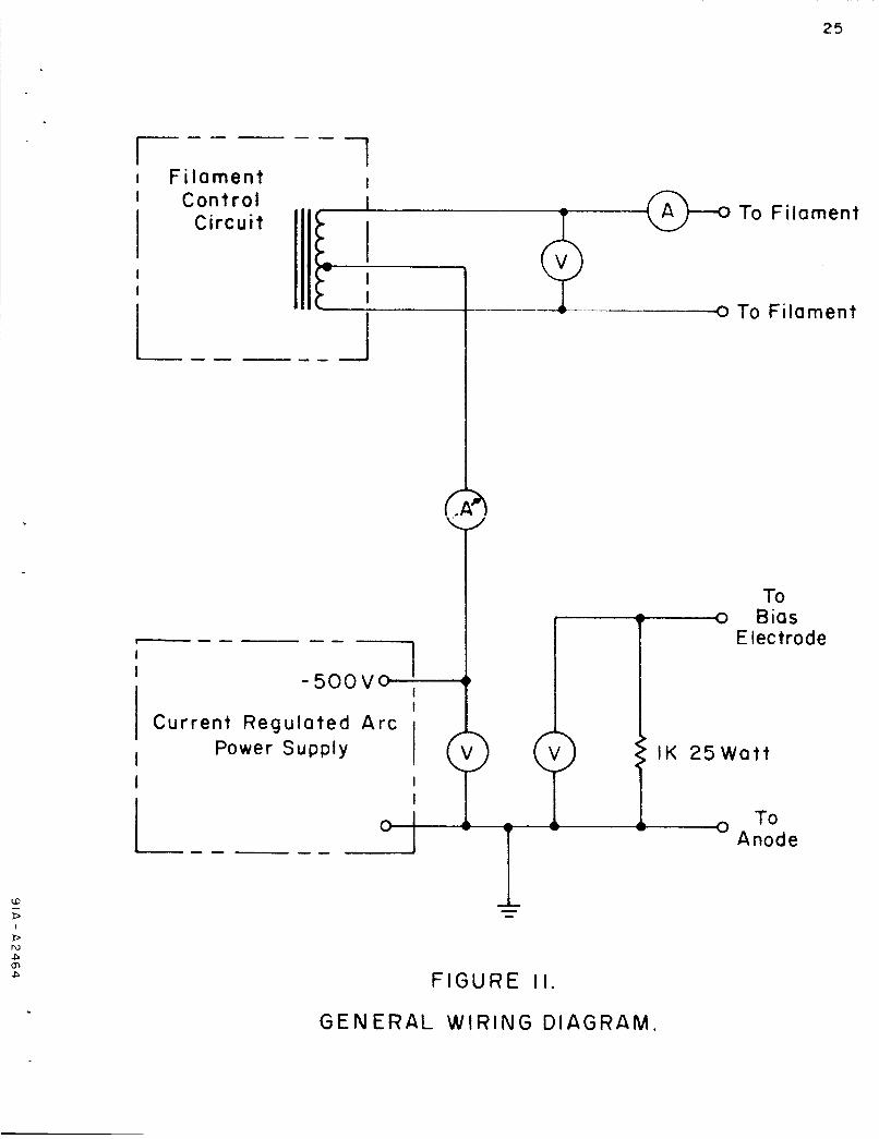
The electronic circuits used incorporate seven panel meters i n order to
permit continual monitoring of the source behavior. The position of each of
these meters is shown schematically in Figure 11. The interconnections
between the filament supply, the bias supply and the current regulated arc
power supply are also shown.
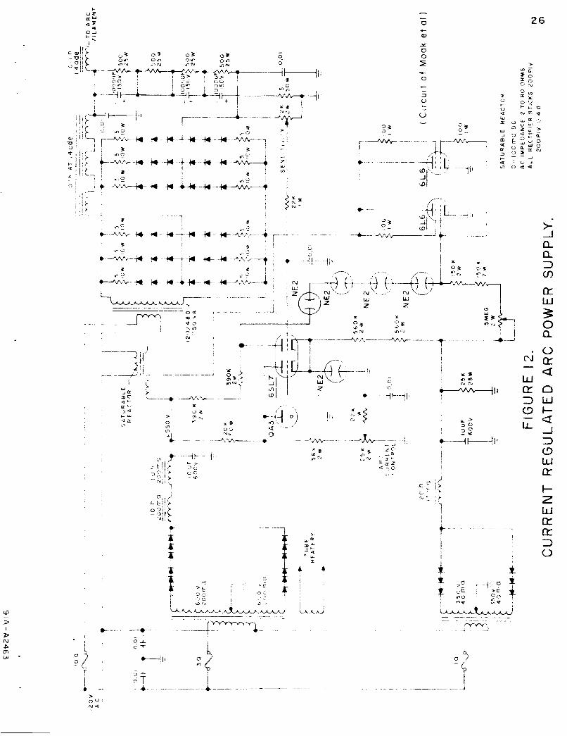
The circuit used for the current regulated arc power supply is shown in
Figure 1 2 . This circuit is the one shown by Moak et a1 (ref. 9) and has been
en ly slightly modified for our use.
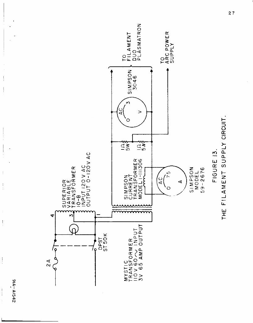
The filament supply is composed of a variac in series with a step down
transformer capable of delivering 60 amperes at3 volts. This is sufficient to
heat .040 inch Tungsten to sufficiently high temperatures for electron e m i s s i o n
to occur. The filament supply circuit is shown in Figure 1 3 .
The magnet supply is a l o w voltage rectified and filtered D. C . circuit .
which provides currents of 3 amperes and 30 volts. It is filtered for better
than 1 % ripple. Because the magnetic field coil is oil cooled, current
regulation is not necessary in this supply. The magnet supply circuit is shown
in Figure 14 . The system power connections are also made in the magnet
supply panel. The collant pump and fan are turned on automatically, when . the main power switch is activated. Power to each of the electronic sub-
assemblies is then controlled individually.
25
I Fi lament I Cnn t rnl
C'rcu't I L L I Fi lament I
I T To Filament I Control
Circuit I
I 1 I
Ill\
I
I 2 To Filament W
9 --A- --o To Filament --I_-
(..A3
T -- 1 ---
I
- 5 00 V eL+ I
1 Current Regulated A r c
I I
Power Supply
FIGURE 1 1 .
G E N E R A L W I R I N G D I A G R A M .
Electrode
I K 2 5 W a t t
To Anode
_I__o
26
t - 2 V L x z I
I -- 1 -.I .
% - 1 I
3
N '\ ... 1 w z W w
z z L
, v v V - - - - -7 I
CJ -
3 (3
lL -
e-+ t-1 I '
R 4 ? I !
q I
9 /
- 5
I
I - -
I .
0
> a
z 0
c u 2 + U Q
a oa = z
0
ircD W O
a N
Y
I- +=) 3a at-
=z= W - 0
2 8
I Q :
w w
-I
>f 0- - V -a
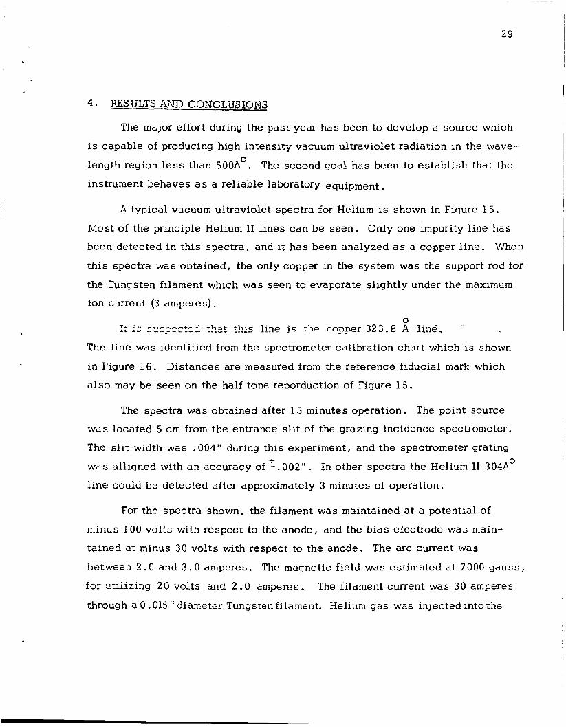
4. RESULTS AND CONCLUSIONS
The mc,jor effort during the past year h a s been to develop a source which
is capable of producing high intensity vacuum ultraviolet radiation in the wave-
length region less than 500AO. The second goal has been to establ ish that the
instrument behaves a s a reliable laboratory equipment.
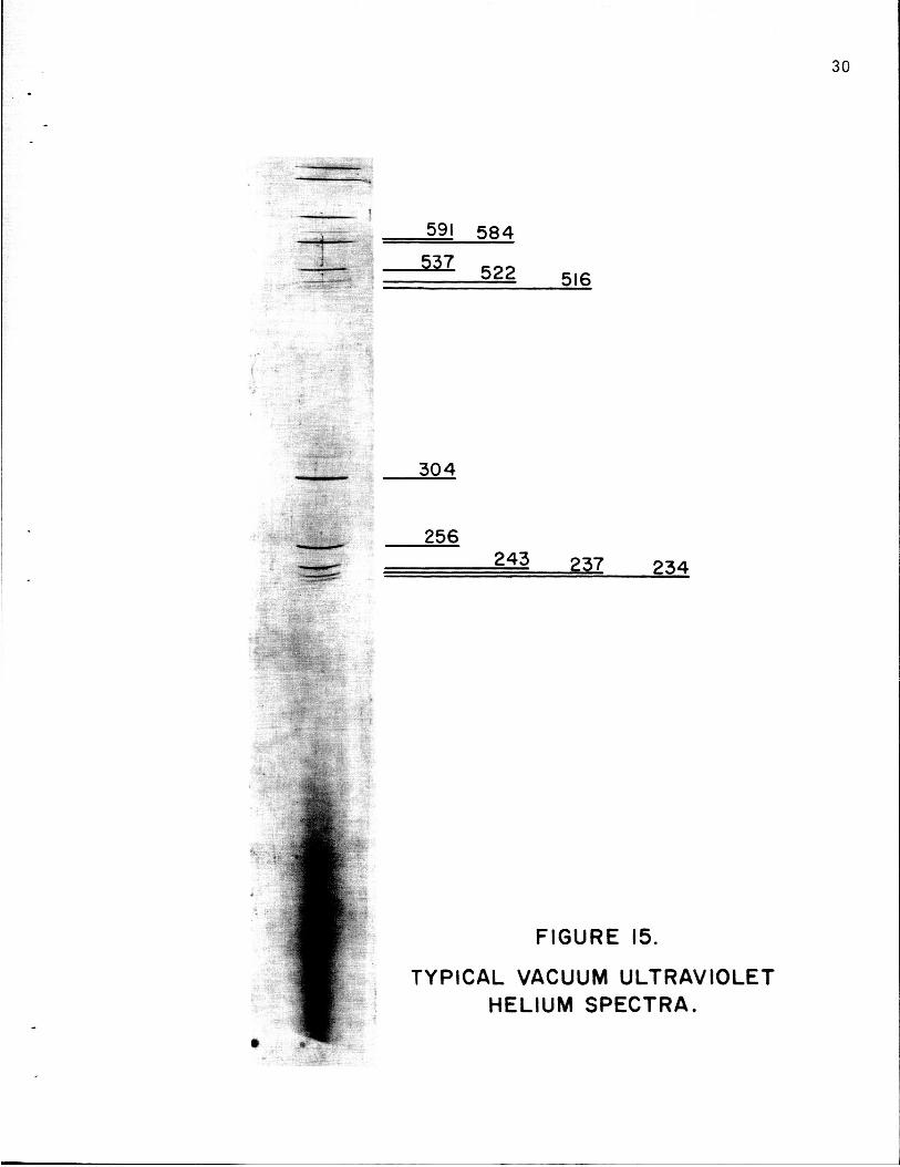
A typical vacuum ultraviolet spectra for Helium is shown in Figure 1 5 .
M o s t of the principle Helium I1 l i n e s can be seen. Only one impurity l i n e has
been detected in this spectra, and it has been analyzed a s a copper l ine. When
this spectra was obtained, the only copper in the system was the support rod for
the Tungsten filament which was seen to evaporate slightly under the maximum
ion current (3 amperes). 0 I: fs sxp:ctcd that t!!is line ic: the copper 323 .8 A line.
The l ine was identified from the spectrometer calibration chart which is shown
in Figure 16 . Distances are measured from the reference fiducial mark which
also m a y be seen on the half tone reporduction of Figure 15.
The spectra was obtained after 15 minutes operation. The point source
was located 5 c m from the entrance slit of the grazing incidence spectrometer.
The slit width was .004" during this experiment, and the spectrometer grating
was alligned with a n accuracy of -.002". In other spectra the Helium I1 304A0
l ine could be detected after approximately 3 minutes of operation.
+
f o r the spectra shown, the filament was maintained at a potential of
minus 100 volts with respect to the anode, and the bias electrode was main-
tained at minus 30 volts with respect to the anode. The arc current was
between 2.0 and 3.0 amperes. The magnetic field was estimated at 7000 gauss ,
for utilizing 20 volts and 2 .O amperes. The filament current was 30 amperes
through a 0.015 " diameter Tungsten filament. Helium gas was injected into the
30
" . . - !
304
256
z43 237 234
FIGURE 15.
TYPICAL VACUUM ULTRAVIOLET HELIUM SPECTRA.
600 1 1 I I I I I 1 1 I I 1 1
580
560
540
520
500
480
460
440
E 420 2 g,ntC)C! a
n
c
c
3 8 0 -
360
340
320
300
200
260
240
220
/<
-
- -
-
-
-
-
-
-
-
-
-
-
-
-
-
-
-
31
32
system with a flow rate estimated at 10-’torr liters/sec. and the base pressure
of the system during operation was 1 x 10 -4 Torr.
The f i l m used was a Kodak SWR f i l m . It was developed in Kodak D-19
developer diluted 1:l from the standard solution with distilled water. The
developer was maintained at 54 F during development. The f i l m was then left
in d standard fixer solution, Mr. Fix01 , for five minutes. Before drying, the
negative was rinsed for 30 seconds in a standard solution of Kodak photoflush.
0
The print was retouched slightly to remove the darkening of the f i l m
which was caused by scattered incident light. The relative intensity of the
l ines remains unchanged.
Problems with the operation of the source demanded a disproportionate
amount or aeveiopmeni iii:ie a11d h u s i;;utvoz:c=! sther spectra from being
obtained. These problems included the failure of Freon 11 3 to provide adequate
cooling, and internal breakdowns between the filament and ground at points close to where the filament electrodes entered the system. Also, an examina-
t ion of the conditions for maximum filament l i f e t i m e was required.
The breakdown problem was finally rectified by changing to the electrode
system shown in Figure 7 . The earlier structure is shown in the Third quarterly
report of this project (Figure 2).
using the platinum mesh filament purchase from Englehard Industries which
w a s dipped into a standard barium-strontium emission solution which was ob-
tained from Raytheon Co. It was found that t he filament limitation was the
sputtering rate of the solution from the platinum grid. With the coated plat-
inum filament there was no control of the cathode potential. Because of the
efficient electron emission it remained at 70 volts during operation.
The longest filament (4 hours) were found
.
33
\ivith Tungsten filaments, t h e cathode fall potential could be contin-
uously varied by adjusting the filament temperature. It is expected that this
is important since this cathode fall potential difference determines the energy
of the electrons which interact in the arc region. With the coated filament ,
no filament heat was required and consequently the cathode voltage was a t a
minimum value of approximately 70 volts. If these cathode fall electrons are
the ones which are essential for causing the high energy spectra, the behavior
of the source is seriously limited with the coated filaments.
The source is now operating satisfactorily and several experiments of
technical interest remain to be performed. The exact requirements for good
spectral behavior have not yet been established. I t is expected that the high
energy specua are obrainea i rom ihe hiyii e ~ e i - j y e i e e t i G Z 5 :kcit cxigiz~tc f r m
the filament. The optimum value h a s not been determined; once this is deter-
mined the modus operandi can be deduced. Other pure gases l i k e Nitrogen and
Hydrogen have not been used with the source. These gases have many excita-
tion l ines in the wavelength range less than 500A". In addition, gases con-
sist ing of m e t a l compounds like iron carbonyl (Reference 10) can be added to
th i s source in order to duplicate portions of the solar spectra. Because the
spectra produced is determined almost completely by the gas injected into
the Duo Plasmatron source, it is expected that the resul ts will be of high
technical value. In addition, the source operates continuously, and from this
beneficial measurements may be made on both detectors and filters which are
effective in this wavelength range.
REFERENCES
1.
2.
8
I .
I L
I .
I
3.
4.
5.
6.
7.
8.
9.
10.
Von Ardenne, M., Tab len Der Electromen Physik Lomenphysik