Available board contains only one.A 3 processor system needs to be
simulated.Random errors are generated in order
to test the system.
Actual ImplementationActual Implementation
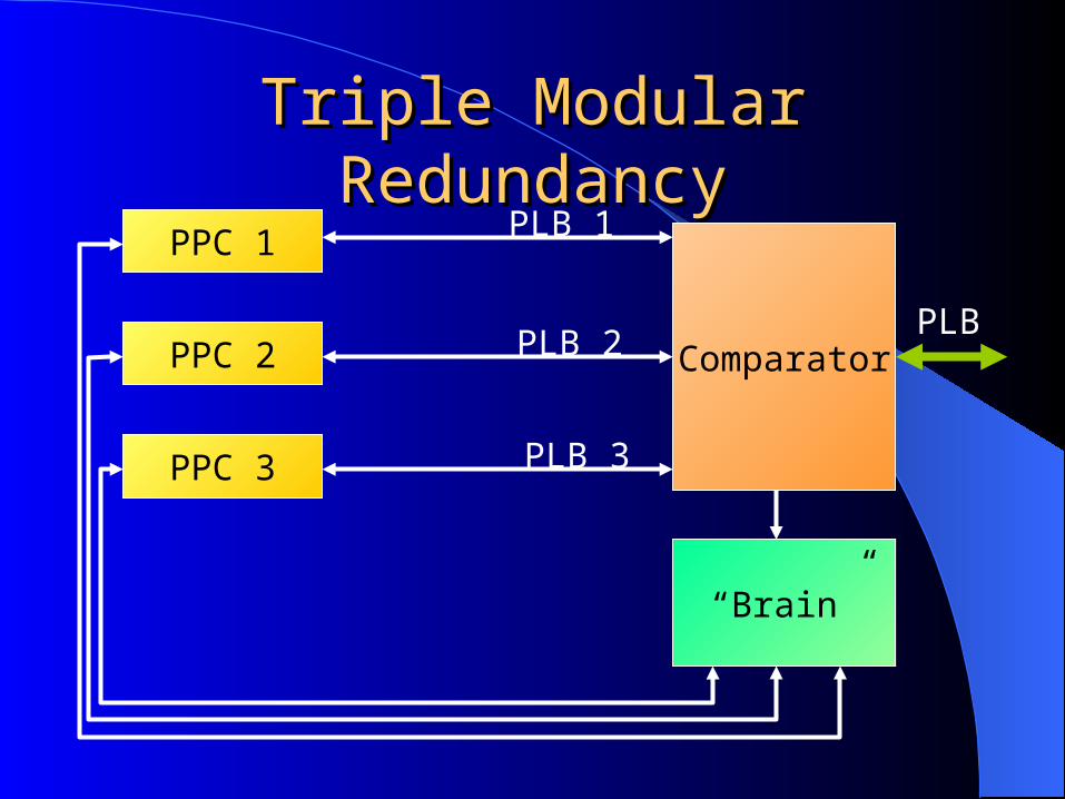
PPC Comparator
Brain
PLB 1
PLB 2
PLB 3
PLB
Bus M
ultiplier
Random
Error G
enerator
Multiple Processor Simulation
Detailed System DiagramDetailed System DiagramPPC
PLB Arbiter
Signal Collector Bus Multiplier
Corrector Arc PLB Sigs
Bus CollectorError Generator
Bus 1Bus 2Bus 3
Comparator
WD
Output Bus
Reset Resolver
TMR Brain
PPC Reset Signals
WDWD
Single Sampler
Capturer
Signal Collection & Signal Collection & ConcatenationConcatenation
Unit Name Source Width
Signal_Collector PowerPC 23
Corrector_Arc PLB Arbiter 133 X 3
PLB_Sigs Corrector_Arc 133
Bus_Multiplier Signal_Collector 23 X 3
Bus_Collector PLB_Sigs & Bus_Multiplier
156
Random Error Generator Random Error Generator Receives the 3 identical busses from the “big
bus” multipliers, and applies an error to one of the busses at random.
ComparatorComparator
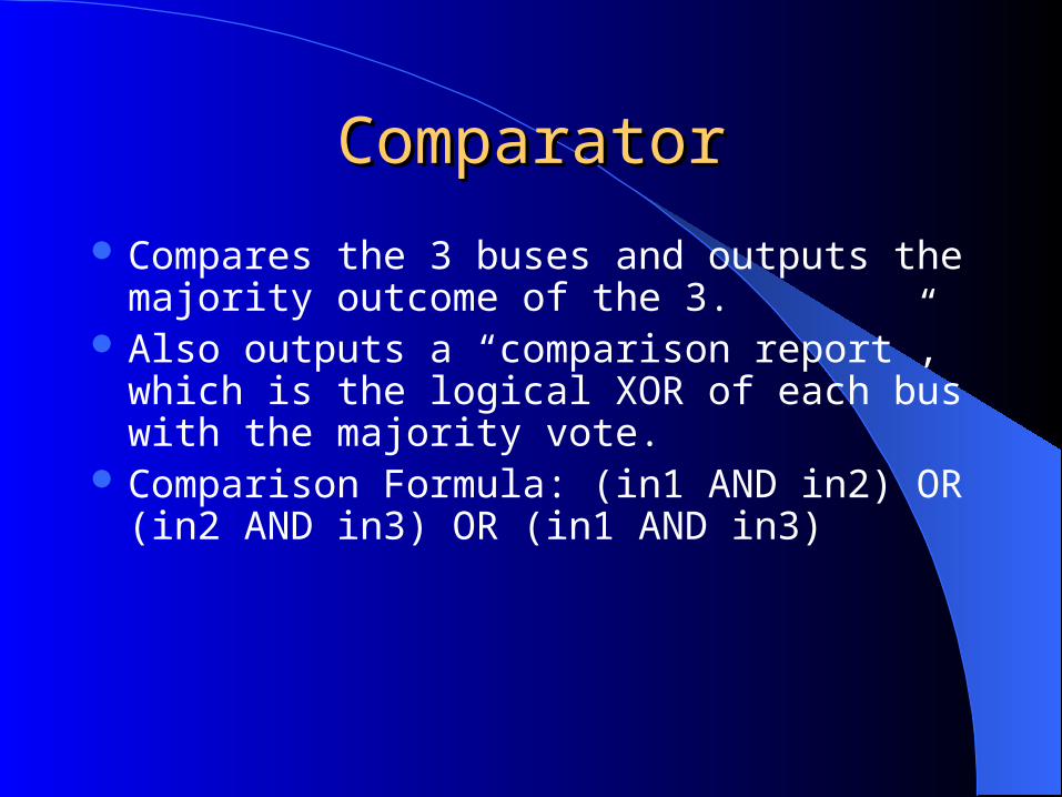
Compares the 3 buses and outputs the majority outcome of the 3.
Also outputs a “comparison report”, which is the logical XOR of each bus with the majority vote.
Comparison Formula: (in1 AND in2) OR (in2 AND in3) OR (in1 AND in3)
Single SampleSingle Sample
Generates a very short error (one clock cycle). Relays the output signals from the comparator to the reset
resolver as usual until a flag signal is asserted. Upon assertion continues relaying the signals for one
more clock cycle and then zeros the signals as if there was no error at all.
Reset ResolverReset Resolver
reads the Comparator’s error reports and checks them for errors.
If one of the signals isn’t all ‘0’, a corresponding error signal is asserted, designating which processor must be reset.
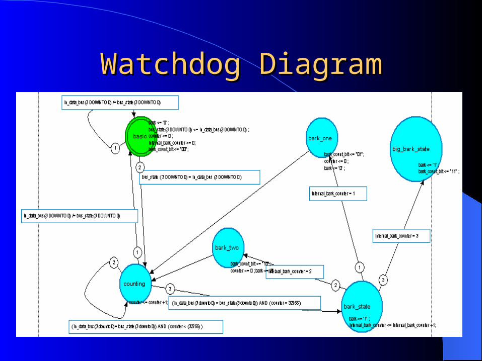
Watchdog UnitsWatchdog Units
listens to bus activity and issues a “bark” signal if the bus becomes idle for an extended period of time.
Issues 3 “warnings” before entering a final bark state.
After 3 counting cycles of no bus activity, the watchdog issues a “big bark”, which requires handling before the watchdog can return to normal operation.
Watchdog DiagramWatchdog Diagram
Watchdog DemonstrationWatchdog Demonstration
TMR BrainTMR Brain
Receives all the monitoring units’ outputs and is in charge of initiating the appropriate correctional activity.
Capturer Capturer
Captures and displays short errors generated by the error generator.
Regularly, displays the outputs of the “Brain”.
Whenever a short error is detected, holds the corresponding error detection signals asserted until a reset occurs.