96
GordonHall RehabilitationMasterPlan
Gordon�Hall��
Rehabilitation�Master�Plan��������������� ���� ��� ��� ���
������������
�
REPORT INTRODUCTION
REHABILITATION MASTER PLAN – AUGUST 2011 GORDON HALL LOCAL HISTORIC DISTRICT PAGE 0-1
TABLE�OF�CONTENTS�REPORT INTRODUCTION .................................................................................................. 0-2
EXECUTIVE SUMMARY .................................................................................................. 0-2ADMINISTRATIVE DATA ................................................................................................. 0-4
NARRATIVE DESCRIPTION ........................................................................................ 0-4STATEMENT OF SIGNIFICANCE ................................................................................ 0-4
SCOPE OF WORK ........................................................................................................... 0-5PROJECT TEAM .............................................................................................................. 0-5DEFINITIONS ................................................................................................................... 0-6
PART 1: DEVELOPMENTAL HISTORY .............................................................................. 1-1HISTORICAL BACKGROUND AND CONTEXT ............................................................... 1-1PERIOD OF SIGNIFICANCE ........................................................................................... 1-2CHRONOLOGY OF DEVELOPMENT AND USE ............................................................. 1-3
EPISODE 1 – THE SAMUEL DEXTER YEARS (1841 – 1843) ..................................... 1-4EPISODE 2 – THE MILLICENT DEXTER YEARS (1863 – MID-1870S) ....................... 1-5EPISODE 3 – THE YEARS OF DECLINE ..................................................................... 1-5EPISODE 4 – THE KATHARINE DEXTER MCCORMICK YEARS ............................... 1-6EPISODE 5 – THE UNIVERSITY OF MICHIGAN YEARS ............................................ 1-7EPISODE 6 – THE DEXTER AREA HISTORICAL SOCIETY AND MUSEUM YEARS 1-7REMARKS .................................................................................................................... 1-8
PART 2: CONDITION AND SYSTEMS ................................................................................ 2-1PHYSICAL DESCRIPTION .............................................................................................. 2-1
SITE .............................................................................................................................. 2-1BUILDINGS ................................................................................................................... 2-3STRUCTURAL SYSTEMS OBSERVATIONS ............................................................. 2-12MECHANICAL SYSTEMS ........................................................................................... 2-16ELECTRICAL SYSTEMS ............................................................................................ 2-18
SYSTEMS ANALYSIS .................................................................................................... 2-23GENERAL ................................................................................................................... 2-23SITE ............................................................................................................................ 2-23BUILDING EXTERIOR................................................................................................ 2-23INTERIOR ................................................................................................................... 2-26HISTORIC INTEGRITY ............................................................................................... 2-28HAZARDOUS MATERIALS ........................................................................................ 2-29CAPACITY FOR EXPANSION.................................................................................... 2-30STRUCTURAL SYSTEMS ANALYSIS ........................................................................ 2-30MECHANICAL SYSTEMS ANALYSIS ........................................................................ 2-34ELECTRICAL SYSTEMS ANALYSIS .......................................................................... 2-36
PART 3: TREATMENT AND USE ........................................................................................ 3-1PLANNING AND ALTERNATIVES ................................................................................... 3-1
BUILDING PROGRAMMING ........................................................................................ 3-1PRESERVATION ZONES ............................................................................................. 3-2
ULTIMATE TREATMENT AND USE ................................................................................ 3-3GENERAL ..................................................................................................................... 3-3RECOMMENDED ALTERNATIVE ................................................................................ 3-4REQUIREMENTS FOR TREATMENT ........................................................................ 3-17
APPENDIX ........................................................................................................................... 4-1 HABS DRAWINGS ........................................................................................................... 4-1HABS PHOTOGRAPHS ................................................................................................... 4-1HABS DATA PAGES ........................................................................................................ 4-1
REPORT INTRODUCTION
REHABILITATION MASTER PLAN – AUGUST 2011 GORDON HALL LOCAL HISTORIC DISTRICT PAGE 0-2
REPORT�INTRODUCTION�
EXECUTIVE�SUMMARY�
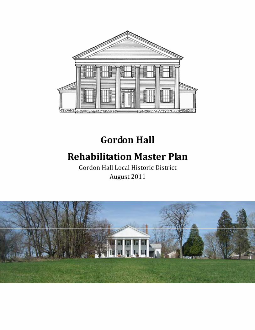
Gordon Hall, owned by the Dexter Area Historical Society and Museum (DAHSM), is a striking example of Greek Revival architecture, on a sweeping 68 acre piece of land just west of Dexter, Michigan. Judge Samuel W. Dexter, founder of the Village of Dexter, built the house in 1843. The house has gone through a long succession of owners, and prior to its purchase by Dexter’s granddaughter Katherine Dexter McCormick - a significant figure in her own right - in 1939 it had fallen into a severe state of disrepair and might have been lost if it were not for her efforts to restore it. Although she did not complete her restoration vision, she saved the house, and donated it to the University of Michigan in 1951. Unfortunately, the University significantly modified the interior, gutting it, converting it to apartments, and obscuring or removing almost all of its interior historic character. However its exterior retained the essential features that gave it a majestic presence that existed since the day it was completed. In 2006 DAHSM purchased the house with the intent of making it a community resource and an extension of its museum activities.
In 2011, DAHSM commissioned the HopkinsBurns Design Studio to produce this Rehabilitation Master Plan to guide and support its future restoration and fundraising efforts.
The Master Plan determined that although Gordon Hall’s historic integrity was compromised by the University of Michigan’s modifications, it was well maintained, and today is in relatively good condition. However, its electrical systems are inadequate, and its central heating system long ago failed, resulting in the installation of an expensive and inefficient electrical radiant heating system. Modifications to the building’s floor framing over time have created some structural inadequacies. The exterior has been completely clad with aluminum siding, although the original clapboard is still present underneath.
The most unfortunate condition is the modifications made to the interior when it was converted to apartments. The arrangement of spaces bears little resemblance to the original dramatic central hall arrangement, and offers little material to help tell the story of the house, its original owner, and its role in the community. Spaces are also small and cramped and thus do not permit the house to be used in a manner that will serve the community and generate an revenue stream necessary to support the house’s maintenance and help pay a large mortgage.
The Master Plan team determined that the a large part of the basic structure that defined the building’s original configuration was still present under the modifications. Accurate
REPORT INTRODUCTION
REHABILITATION MASTER PLAN – AUGUST 2011 GORDON HALL LOCAL HISTORIC DISTRICT PAGE 0-3
restoration of the interior to its historic configuration was found to be feasible due to the existence of detailed drawings from the Historic American Building Survey (HABS) archives. In addition, reconstructing a missing “ell” that was once attached to the north wall of the house could create additional useful space that could be used to generate revenue.
The Master Plan Team also worked with the DAHSM to determine programming for the facility based on the organization’s vision that Gordon Hall should be a resource to the community, and developed a plan for implementation that would lead to the restoration of the interior and exterior, and permit the building to be available to the community, generate revenue, and provide space for the museum’s historical exhibits, outreach programs and educational efforts.
The plan was prioritized into three levels, based on urgency of work required. Work needed to protect the integrity of the building would be the highest priority. Subsequent phases would move toward the eventual full restoration of the building.
Budgets were established for the priority levels as follows:
� Priority One: $80,106
� Priority Two: $105,288
� Priority Three: $52, 492.
In addition, to this work, major restoration work on the building and site was identified as follows:
� Interior and Exterior Restoration: $836,880
� Reconstruction of the “Ell”: $499,421
� Construction of new Outbuildings: $1,813,359 (includes the construction of a barn with modern amenities and climate control to accommodate a new museum.)
The outbuildings would be compatible with the historic character of the property, and would seek to recall the imagery of the 19th century farm yard.
Because the major restoration work is highly dependant on fundraising, the budget is structured so that the restoration items could be implemented as part of either Priority Two or Three.
At the conclusion of this work, Gordon Hall will be restored to its 19th century glory and will be on the road to self sufficiency, while providing an important historical resource and focal point for the community.

REPORT INTRODUCTION
REHABILITATION MASTER PLAN – AUGUST 2011 GORDON HALL LOCAL HISTORIC DISTRICT PAGE 0-4
ADMINISTRATIVE�DATA�The Gordon Hall Historic District, herein referred to as Gordon Hall, is located at:
8347 Island Lake Road Dexter, MI Washtenaw County
It is currently owned and maintained by the Dexter Area Historical Society & Museum (DAHSM).
Gordon Hall was listed on the State of Michigan Register of Historic Sites on February 19, 1958, and listed in the National Register of Historic Places on November 9, 1972. The Gordon Hall Historic District was designated as a Washtenaw County Local Historic District on October 17, 2001. The national register listing indicates the period of significance as 1826-1865.
Gordon Hall was commissioned by Judge Samuel W. Dexter, a significant person and was built by Calvin T. Fillmore.
The following summaries of Gordon Hall are drawn from the Michigan Historic Sites Online website: www.mcgi.state.mi.us/hso/sites/14898.htm.
� NARRATIVE�DESCRIPTION�“The Judge Samuel W. Dexter House (Gordon Hall) is a rectangular, temple-front, Greek Revival frame building with a two-story central mass flanked by one-and-one-half-story, side-gable wings. A massive full-height tetrastyle [sic, hexastyle] Doric portico fronts the entrance facade flanked by slope-roofed single-story porches. The house is currently covered with aluminum siding but retains many of its original exterior features. The interior has been significantly remodeled into apartments.”
� STATEMENT�OF�SIGNIFICANCE�“The Judge Samuel W. Dexter House is one of the most striking Greek Revival homes in Michigan, unique for its grand scale with well-balanced proportions and massive tetrastyle [sic, hexastyle] portico. The house was completed in 1844 for Judge Samuel W. Dexter, chief justice of Washtenaw County from 1826 to 1833, founder of the city of Dexter, and a University of Michigan Regent. Restored in the 1940s by Emil Lorch, professor emeritus of architecture at the University of Michigan, the interior of the house was altered radically when the house was converted into apartments in 1951. Gordon Hall is currently used for faculty housing.*”
* When the Statement of Significance was written Gordon Hall was used as faculty housing. As of 2011 it is unoccupied, and used intermittently for tours, to host student group events.
REPORT INTRODUCTION
REHABILITATION MASTER PLAN – AUGUST 2011 GORDON HALL LOCAL HISTORIC DISTRICT PAGE 0-5
SCOPE�OF�WORK�In November, 2010, Washtenaw County Government, a Certified Local Government, and the Dexter Area Historical Society and Museum, a 501(c)(3) non-profit, commissioned HopkinsBurns Design Studio to develop a Rehabilitation Master Plan for Gordon Hall, a Washtenaw County Local Historic District.
The intent of the Master Plan as stated in the project’s Request For Proposal was as follows:
“…The DAHSM Board and current benefactors of Gordon Hall desire to form a clear plan for the care, use, and future maintenance of the historic 19th century house and ancillary buildings. Little funding has been available for the maintenance or rehabilitation of this site, which has mounting issues related to its long-term preservation. This present lack of management plan has also placed limitations on the public, private, and school programs held at Gordon Hall.
The purpose of this project is to conduct an existing conditions assessment of Gordon Hall, its ancillary structures, and surrounding landscape. This assessment will result in a prioritized schedule of recommended actions for the near-term, mid-term, and long-term maintenance and rehabilitation of the property. A thorough investigation of the site’s existing conditions, historical development and significance, maintenance issues, and action steps for rehabilitation would provide direction for the DAHSM’s future maintenance of the site. This rehabilitation master plan would complement an existing National Register listing and local historic designation, the latter of which is presently overseen by the Washtenaw County Historic District Commission…”
This project is funded in part with federal funds from the U.S. Department of the Interior, National Park Service through the Michigan State Housing Development Authority (MSHDA). The grant for this project is based on a grant agreement between Washtenaw County Government and Michigan State Housing Development Authority, State Historic Preservation Office.
PROJECT�TEAM�The HopkinsBurns project team consisted of:
HopkinsBurns Design Studio Architecture and Historic Preservation Services
� Eugene C. Hopkins, FAIA, Team Leader, Historic Preservation Architect � Gregory A. Jones, AIA, Technical Preservation Architect � David B. Rochlen, Assoc. AIA, Technical Staff/Intern Architect
Robert Darvas Associates Consulting Structural Engineers
REPORT INTRODUCTION
REHABILITATION MASTER PLAN – AUGUST 2011 GORDON HALL LOCAL HISTORIC DISTRICT PAGE 0-6
� Stephen M. Rudner, P. E., Structural Engineer
TAC Associates, LLC Consulting Engineers
� Thomas G. Crow, P.E., LEED AP, Electrical Engineer
Potapa - Van Hoosear Engineering, Inc. Consulting Engineers
� Karl Potapa, P. E., Mechanical Engineer
Johnson Hill Land Ethics Landscape Architecture
� Chester B. Hill, ASLA, Landscape Architect
DEFINITIONS�Main Block: The central 2-story portion of Gordon Hall.
The Building, Main Building: Refers to the entire main structure on the site (Gordon Hall), including the two attached wings
Historical Displays: Boards, photographs, and small free standing exhibits depicting or describing historical events.
Wings: The small 1½ story structures attached to the northwest and southwest corners of the Main Block.
Outbuildings: Structures on the site, other than the Main Building, Gordon Hall.
Site: The entire Gordon Hall Site, including buildings, structures, roads, walkways, site amenities, land, and vegetation
PART 1: DEVELOPMENTAL HISTORY
REHABILITATION MASTER PLAN – AUGUST 2011 GORDON HALL LOCAL HISTORIC DISTRICT PAGE 1-1
PART�1:�DEVELOPMENTAL�HISTORY�
This section documents the history and evolution of the Gordon Hall Historic District. The information in this section is both a summary and a continuation of the research presented in the Gordon Hall Final Report, September 10, 2001 created by the Gordon Hall Historic District Study Committee.
HISTORICAL�BACKGROUND�AND�CONTEXT�This section briefly describes the key people and notable events that created the particular history associated with Gordon Hall.
Samuel William Dexter, born in Boston in 1792, was the son of Samuel Dexter, a U.S. senator and cabinet member under Presidents John Adams and Thomas Jefferson. After receiving a law degree from Harvard University in 1815, the young Samuel W. Dexter married Amelia Augusta Provost the following year. The couple, living in Athens, New York, had two sons Samuel Prevost and Augustine. Tragically, Amelia and Augustine died in 1822; two years later in 1824, Samuel W. Dexter moved from New York to Washtenaw County, MI.
In Michigan, Dexter founded the village of “Dexter,” naming it to honor his father. He began to establish himself as a pillar of the community by surveying land, purchasing property, founding a post office and building a saw mill, a grist mill and a boarding house. In 1825, one year after moving to Michigan, Samuel W. Dexter married his second wife Susan Dunham and in 1826 he was appointed the first Chief Justice of Washtenaw County. Tragedy again stuck the Dexter family in 1827 when Susan and their young son died. The following year, now Judge (and Postmaster) Dexter, married Millicent Bond (1812-1899) whose family had recently moved to Michigan from Massachusetts.
In 1837, Judge Dexter, an early proponent of the transcontinental railroad, deeded land near his house to the state of Michigan to be used by the rail line that would run through Dexter. The trains finally came to Dexter in 1841 and it was at this time that Judge Dexter commissioned a mansion to be built just outside the village of Dexter on 1700 acres of his own land.
Over the next three years, Judge Dexter worked with local architect Calvin T. Fillmore (1810-1879), brother of U.S. president Millard Fillmore, to design and build Gordon Hall named to honor the family of his mother, Catherine Gordon Dexter. In 1843, Fillmore and his construction team that included the carpenter Sylvester Newkirk completed their work on the Greek revival mansion. Judge Dexter lived in Gordon Hall with his family for the next twenty years until his death in 1863 and during this time the home was visited

PART 1: DEVELOPMENTAL HISTORY
REHABILITATION MASTER PLAN – AUGUST 2011 GORDON HALL LOCAL HISTORIC DISTRICT PAGE 1-2
by two, possibly three U.S. presidents. It is also probable that the home was used as a “station” on the Underground Railroad, as evidenced by many historic accounts. The HABS drawings indicate a trapdoor on the south porch leading to a crawlspace, which could have been used as a hiding place during this time period.
In 1863 Samuel W. Dexter passed away leaving Millicent Dexter in charge of the estate. She made several changes to Gordon Hall including removing the southwest wing and building the four-story tower in its place. Over the next decade, Judge Dexter’s son, Wirt Dexter, sold off much of the land; in 1875 seventy acres remained. In 1899 Millicent Dexter died, the house was sold and, according to the wishes expressed in her will, the proceeds were divided amongst her daughters.
Thomas Birkett, a local banker, land owner and businessman, purchased Gordon Hall in 1900. At the time of his death, in 1916, Gordon Hall was in poor condition. Dr. Charles G. Crumrine, a retired medical practitioner in ailing health, purchased the house and in 1919 began to rehabilitate it. His son, Charles G. Crumrine, Jr. rented out the house after his father’s death, but then after some time began to neglect the house and it fell into disrepair.
Katharine Dexter McCormick, granddaughter of Judge Dexter and daughter of Wirt Dexter and his second wife Josephine, purchased Gordon Hall in 1939 after hearing of the poor status of the estate from U. S. Senator Royal Smith from New York, who was raised in Dexter. Katharine Dexter McCormick was born in Gordon Hall in 1875. She was the second female graduate of Massachusetts Institute of Technology (1904), a trained scientist, a leader of the suffrage movement, and the pioneering benefactor of oral contraceptive research. She was inducted into both the National Women's Hall of Fame (1998) and the Michigan Women's Hall of Fame (2000).
Katharine Dexter McCormick wished to perform a restoration of the home and to that end hired Emil Lorch, dean emeritus of the University of Michigan's College of Architecture. Dean Lorch spent the next eight years working on restoring the house; however, before the rehabilitation was complete, Katharine Dexter McCormick donated the home to the University of Michigan. In 1951, after much controversy, an interior conversion to apartments was completed by the University of Michigan and Gordon Hall became a home to university faculty and staff, one of the first being retired university president, Alexander G. Ruthven.
On March 15, 2006 the University of Michigan sold the 67.68 acre Gordon Hall site to the Dexter Area Historical Society. In 2009, DAHSM sold 15 acres in the northwest corner of the site to the United Methodist Retirement Community, Inc. (UMRC), who subsequently constructed a residential development on the property.
PERIOD�OF�SIGNIFICANCE�The National Register of Historic Places listing and State of Michigan Register of Historic Sites indicates the Period of significance as 1826 to 1865. This period starts with Samuel W. Dexter’s arrival in Michigan, and ends two years after his death in 1863, when his widow Millicent began to make changes to the property. It encompassed the time when Dexter rose to prominence, establishing the village of Dexter, becoming a Postmaster and Judge, and establishing important business and services in the area. It

PART 1: DEVELOPMENTAL HISTORY
REHABILITATION MASTER PLAN – AUGUST 2011 GORDON HALL LOCAL HISTORIC DISTRICT PAGE 1-3
also encompasses the time when he built Gordon Hall, a significant example of Greek Revival architecture in Michigan, and lived in it for 20 years.
The writers of this report take no exception to this period of significance. Certainly others who followed Judge Dexter as owners of Gordon Hall after 1863 had a hand in shaping and modifying its physical presence, however they did not have his combination of local historical impact and architectural vision, and thus do not justify extending the Period of Significance beyond 1863.
Dexter’s widow Millicent made major additions, but unfortunately they only served to diminish the house’s essential architectural character for which it is significant. Although Millicent was active in the community, she did not have the broad historical impact that her late husband had on the area. Later, Judge Dexter’s granddaughter, Katharine Dexter McCormick, notable in her own right on a state and national level as a leading suffragette, co-founder of the League of Women Voters, and sponsor of research in the field of oral contraceptives, had an impact on the home by rescuing it when it was in a state of major decline. She initiated restoration efforts at Gordon Hall, under the guidance of architect Emil Lorch. However, her changes were directed at restoring the house to the configuration that existed when her grandfather was alive, and did not represent a new vision that originated with her. In many ways, the entity that had the greatest impact on Gordon Hall after Judge Dexter was the University of Michigan. Although their ownership permitted the Building to survive until the DAHSM purchased it in 2006, their impact was the most detrimental, removing nearly all interior historic fabric in the process of converting it to apartments.
CHRONOLOGY�OF�DEVELOPMENT�AND�USE��The following chronology is based on information contained in Gordon Hall – Historic District Committee Final Report dated September 10, 2001, and supplemented with physical observations by the project team for this report. Under ideal circumstances, detailed physical investigations would provide verification of written history. At Gordon Hall, the extensive interior renovations in 1951 removed much of the historic fabric that might provide evidence that could confirm the evolution derived from the building’s written history. At the exterior, the total cladding of the building with aluminum siding and trim similarly renders it difficult to find physical evidence to verify written accounts.
Today, the basement, which is the least-modified area of the building, offers the best opportunity to verify chronology, however the major changes occurred above that level. Observations in the basement confirm the location of the original staircase, and show evidence of the subsequent excavation of the south basement under the main block of the house. Observations in the northwest wing verify the 1951 concrete foundation construction. In the southwest basement, observations are consistent with written accounts of features believed to relate to Underground Railroad activities. However the vintage of that basement cannot be definitively determined.
It is fortunate that much of the evolution of the house is quite clear, and that the main block of the house (especially the interior) appears to have been largely unchanged from 1843 to 1951. A detailed set of Historic American Buildings Survey (HABS) drawings and accompanying photographs from 1934 depict the interior and exterior of the building at that date in great detail. Other pre-1951 photographs show the exterior configuration

PART 1: DEVELOPMENTAL HISTORY
REHABILITATION MASTER PLAN – AUGUST 2011 GORDON HALL LOCAL HISTORIC DISTRICT PAGE 1-4
of much of the exterior of the building. Finally, a newspaper article with photographs taken during the 1951 remodeling showing portions of the building during selective demolition provides further insight into the changes that occurred behind the walls at that time. Careful examination of such available historical documentation, and comparison with conditions that can be viewed today provided information that was used to corroborate written accounts of the building’s evolution. Based on this analysis, the chronology presented below represents the most likely, although not 100% certain, evolution of Gordon Hall.
Although the chronology presented here is well supported by documentation and photographs, there is still some uncertainty about the time and configuration of some elements. Refer to Remarks at the end of the Episodes for a listing of some of the uncertainties.
EPISODE�1�–�THE�SAMUEL�DEXTER�YEARS�(1841�–�1843)��� Judge Samuel William Dexter builds Gordon Hall, in Greek Revival style on 1700
acres of land that he already owned. o Original configuration consisted of the Doric porticoed main two-story
block of the house, and is believed to have included two square one-and-one-half story wings at the northwest and southwest corners of the main block, although there is some uncertainty as to the original configuration and size of the northwest wing (refer to Remarks below). A rear porch filled the space between the two wings. The northwest wing contained the kitchen. The footprint of that original main block and wings is believed to be nearly identical to the footprint that exists today.
o The interior arrangement was a classic Greek Revival central hall style, with a main central hall at the first and second floor connected by a open staircase. Flanking the hall on both floors were two nearly-square rooms, two on each side of the hall. This original interior spatial configuration survived until the 1951 remodeling.
o Based on observations made by the team preparing this report, the basement appears to have consisted of a full basement under the north two-thirds of the main block of the building, with a crawl space under the south third. It appears that the east end of the south main basement may have been excavated deeper than the remainder of the basement.
o The space under the southwest wing is said to have been a basement, used as part of Underground Railroad activities. Observations reveal concrete infills and openings that are consistent with written accounts of how the house may have been used to conceal escaped slaves.
o The space under the northwest “ell” extension may have been a basement, or a crawl space. The 1934 HABS drawings indicate a basement; it is not known if that was an original configuration or not.
1843�OR�CIRCA�1850S:��� It is believed that at some point during this time period the original small
northwest wing was extended to the north, and then turned to the west, creating an “ell” (it also is possible that this ell may have been part of the original construction. See Remarks below). This ell addition contained kitchen, servants' quarters, pantry, laundry, and a large open carriage shed. The 1934 HABS
PART 1: DEVELOPMENTAL HISTORY
REHABILITATION MASTER PLAN – AUGUST 2011 GORDON HALL LOCAL HISTORIC DISTRICT PAGE 1-5
drawings show the ell, with what appears to be a full basement under the portion that would have been the small original wing, and what appears to be a crawl space under the remainder of the ell. The drawing shows a thick dividing wall between the basement and crawl space. This configuration tends to support the theory that the small square wing may have been built first as a complete element, with the remainder of the ell being a later addition.
CIRCA�1850:�� Store House was built.
1863:�� Judge Samuel William Dexter dies; widow, Millicent continues to live at Gordon
Hall.
EPISODE�2�–�THE�MILLICENT�DEXTER�YEARS�(1863�–�MID�1870S)��
� Southwest wing was removed and replaced with a four-story tower with continuous four-story bay window.
� Gardens south of house were abandoned. � Southern portion of north ell was expanded to two full stories in height, adding
bedrooms and support spaces.
1865:�� Cut stone privy constructed in area of former gardens south of the house.
1863�1875:�� Construction of second privy – 1865. � Gradual selling off of portions of Judge Dexter’s original property by his son, Wirt,
ending in 1875. This takes the site down to approximately 67 acres, which includes the current site plus the Cedar’s acreage.
1899:�� Millicent Dexter dies.
EPISODE�3�–�THE�YEARS�OF�DECLINE�
1900:�� Gordon Hall sold to Thomas Birkett.
CIRCA�1910:�� Two large barns burned down.
PART 1: DEVELOPMENTAL HISTORY
REHABILITATION MASTER PLAN – AUGUST 2011 GORDON HALL LOCAL HISTORIC DISTRICT PAGE 1-6
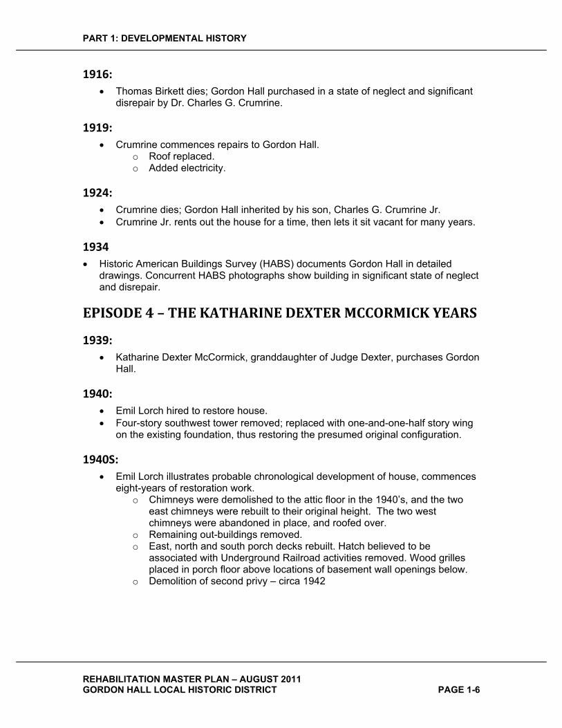
1916:�� Thomas Birkett dies; Gordon Hall purchased in a state of neglect and significant
disrepair by Dr. Charles G. Crumrine.
1919:�� Crumrine commences repairs to Gordon Hall.
o Roof replaced. o Added electricity.
1924:�� Crumrine dies; Gordon Hall inherited by his son, Charles G. Crumrine Jr. � Crumrine Jr. rents out the house for a time, then lets it sit vacant for many years.
1934�� Historic American Buildings Survey (HABS) documents Gordon Hall in detailed
drawings. Concurrent HABS photographs show building in significant state of neglect and disrepair.
EPISODE�4�–�THE�KATHARINE�DEXTER�MCCORMICK�YEARS�
1939:�� Katharine Dexter McCormick, granddaughter of Judge Dexter, purchases Gordon
Hall.
1940:�� Emil Lorch hired to restore house. � Four-story southwest tower removed; replaced with one-and-one-half story wing
on the existing foundation, thus restoring the presumed original configuration.
1940S:�� Emil Lorch illustrates probable chronological development of house, commences
eight-years of restoration work. o Chimneys were demolished to the attic floor in the 1940’s, and the two
east chimneys were rebuilt to their original height. The two west chimneys were abandoned in place, and roofed over.
o Remaining out-buildings removed. o East, north and south porch decks rebuilt. Hatch believed to be
associated with Underground Railroad activities removed. Wood grilles placed in porch floor above locations of basement wall openings below.
o Demolition of second privy – circa 1942

PART 1: DEVELOPMENTAL HISTORY
REHABILITATION MASTER PLAN – AUGUST 2011 GORDON HALL LOCAL HISTORIC DISTRICT PAGE 1-7
EPISODE�5�–�THE�UNIVERSITY�OF�MICHIGAN�YEARS�
1951:�� Katharine Dexter McCormick donates Gordon Hall property to the University of
Michigan.� Major remodeling undertaken by the University of Michigan to convert the building
into four apartments. o Interior of house gutted and most interior details and finishes removed. o Date assumed – two abandoned west chimneys removed to the first floor
level. New window added at second floor where chimney had been. o Dormer added to west side of existing southwest wing. o Two-story north wing and ell removed; replaced with new one-and-one-half
story wing matching southwest wing, on a new reinforced concrete foundation.
1951:�� Rear (west) porch floor replaced with concrete. � Roof sitting deck added above rear (west) porch. � Grassy rear yard established and wood fence added. � Line of cedars added along back fence.
CIRCA�1950S:�� Surviving maple trees along formal approach to house removed.
1956:�� Four car garage built of concrete masonry units, attached to Store House (Some
reports date the garage at 1951). � Two ranch style houses built northwest of Gordon Hall, to be rented to university
personnel. Construction was funded by money left to the University by Katharine Dexter McCormick.
1956:�� Building clad in aluminum siding (circa 1974).
EPISODE�6�–�THE�DEXTER�AREA�HISTORICAL�SOCIETY�AND�MUSEUM�YEARS�
2006:�� The University of Michigan sells the Gordon Hall property to the Dexter Area
Historical Society and Museum.
2009:�� Demolition of two ranch houses. � Construction of Cedars of Dexter retirement community by UMRC.
PART 1: DEVELOPMENTAL HISTORY
REHABILITATION MASTER PLAN – AUGUST 2011 GORDON HALL LOCAL HISTORIC DISTRICT PAGE 1-8
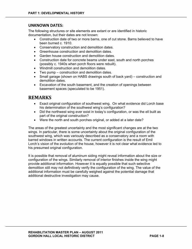
UNKNOWN�DATES:�The following structures or site elements are extant or are identified in historic documentation, but their dates are not known:
� Construction date of two or more barns, one of cut stone. Barns believed to have been burned c. 1910.
� Conservatory construction and demolition dates. � Greenhouse construction and demolition dates. � Garden house construction and demolition dates. � Construction date for concrete beams under east, south and north porches
(possibly c. 1940s when porch floors were rebuilt). � Windmill construction and demolition dates. � Two pump – construction and demolition dates. � Small garage (shown on HABS drawings south of back yard) – construction and
demolition dates. � Excavation of the south basement, and the creation of openings between
basement spaces (speculated to be 1951).
REMARKS�� Exact original configuration of southwest wing. On what evidence did Lorch base
his determination of the southwest wing’s configuration? � Did the northwest wing ever exist in today’s configuration, or was the ell built as
part of the original construction? � Were the north and south porches original, or added at a later date?
The areas of the greatest uncertainty and the most significant changes are at the two wings. In particular, there is some uncertainty about the original configuration of the southwest wing, which was variously described as a conservatory and a room with barred windows in written accounts. The current configuration is the result of Emil Lorch’s vision of the evolution of the house, however it is not clear what evidence led to his presumed original configuration.
It is possible that removal of aluminum siding might reveal information about the size or configuration of the wings. Similarly removal of interior finishes inside the wing might provide additional information. However it is equally possible that such selective demolition still may not definitively verify the configuration of the wing. The value of the additional information must be carefully weighed against the potential damage that additional destructive investigation may cause.

PART 2: CONDITION AND SYSTEMS
REHABILITATION MASTER PLAN – AUGUST 2011 GORDON HALL LOCAL HISTORIC DISTRICT PAGE 2-1
PART�2:�CONDITION�AND�SYSTEMS��
The information presented in this section regarding the current condition of the site and structure is based on a physical examination of Gordon Hall by the Project Team on March 23, 2011 and April 29, 2011.
PHYSICAL�DESCRIPTION��
SITE�The site consists of a 67.68 acre triangular parcel of land bounded by Dexter-Pinckney and Island Lake Roads on the northeast, railroad tracks on the southeast, and a subdivision to the west (see Site Plan, Sheet 0). The northwest corner of the triangle was sold to United Methodist Retirement Community, Inc. in 2009 who built a housing development for active seniors called the Cedars of Dexter, completed in 2010. The site has gently rolling topography, generally sloping down from west to east. The west edge of the site is lined with trees, and the corner with the housing development has a moderately dense distribution of trees as well. The remainder of the site is open, with vegetation consisting of grasses or hay. A detention pond constructed to serve the Cedars development is located along the northeast boundary of the site. Gordon Hall sits in a commanding location near the center of the western portion of the triangle at the top of the broadly sloping grassy ridge, with dramatic view toward the Village of Dexter, encompassing nearly 180 degrees.
Views of the site from surrounding roads are as dramatic as the view from the house, dominated by Gordon Hall’s dramatic temple-like presence at the top of the broad front yard.
The site has a curving driveway leading to Gordon Hall from a point near the intersection of Dexter-Pinckney and Island Lake Roads. The driveway leads to a small parking area north of the house.
In addition to the main Gordon Hall structure, the site has a brick masonry Store House to the northwest of the house, with a concrete block four-car garage attached to its east wall.
To the west of the house is a rectangular back yard enclosed by a wood fence. Southwest of the house are foundation remnants from an earlier barn. Trees along the west property line extending toward the house screen the view of the adjacent subdivision from the back yard and rear porch.
PART 2: CONDITION AND SYSTEMS
REHABILITATION MASTER PLAN – AUGUST 2011 GORDON HALL LOCAL HISTORIC DISTRICT PAGE 2-2
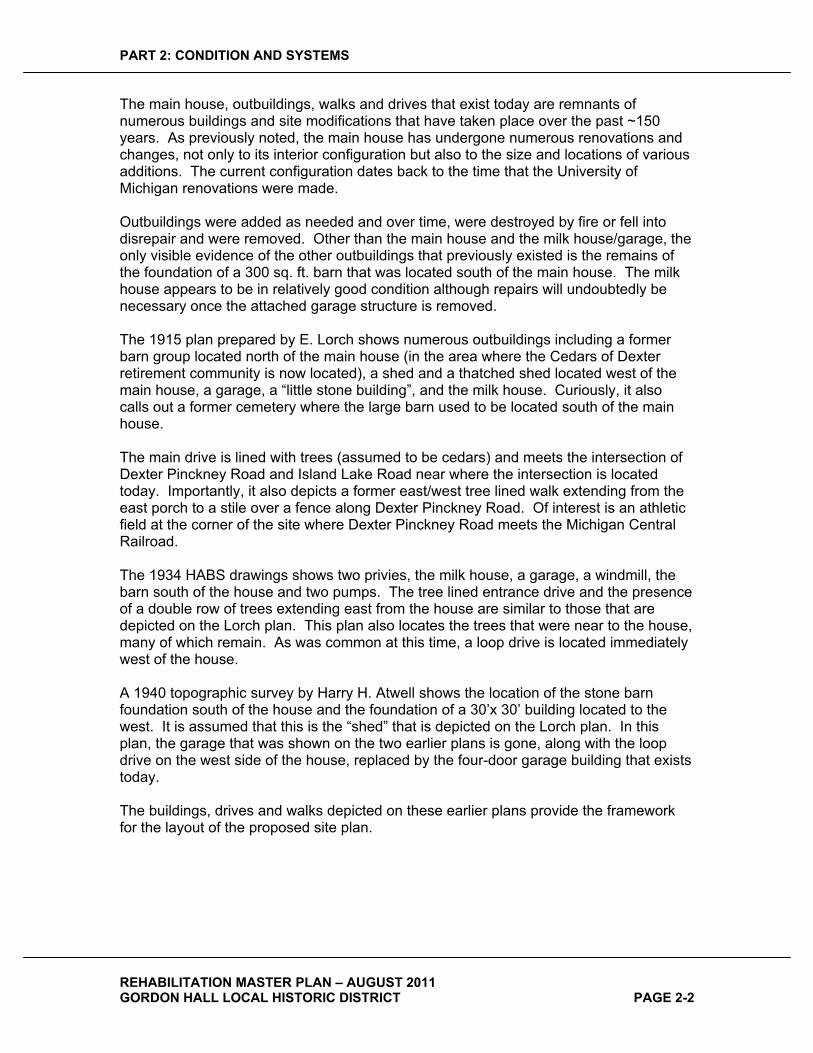
The main house, outbuildings, walks and drives that exist today are remnants of numerous buildings and site modifications that have taken place over the past ~150 years. As previously noted, the main house has undergone numerous renovations and changes, not only to its interior configuration but also to the size and locations of various additions. The current configuration dates back to the time that the University of Michigan renovations were made.
Outbuildings were added as needed and over time, were destroyed by fire or fell into disrepair and were removed. Other than the main house and the milk house/garage, the only visible evidence of the other outbuildings that previously existed is the remains of the foundation of a 300 sq. ft. barn that was located south of the main house. The milk house appears to be in relatively good condition although repairs will undoubtedly be necessary once the attached garage structure is removed.
The 1915 plan prepared by E. Lorch shows numerous outbuildings including a former barn group located north of the main house (in the area where the Cedars of Dexter retirement community is now located), a shed and a thatched shed located west of the main house, a garage, a “little stone building”, and the milk house. Curiously, it also calls out a former cemetery where the large barn used to be located south of the main house.
The main drive is lined with trees (assumed to be cedars) and meets the intersection of Dexter Pinckney Road and Island Lake Road near where the intersection is located today. Importantly, it also depicts a former east/west tree lined walk extending from the east porch to a stile over a fence along Dexter Pinckney Road. Of interest is an athletic field at the corner of the site where Dexter Pinckney Road meets the Michigan Central Railroad.
The 1934 HABS drawings shows two privies, the milk house, a garage, a windmill, the barn south of the house and two pumps. The tree lined entrance drive and the presence of a double row of trees extending east from the house are similar to those that are depicted on the Lorch plan. This plan also locates the trees that were near to the house, many of which remain. As was common at this time, a loop drive is located immediately west of the house.
A 1940 topographic survey by Harry H. Atwell shows the location of the stone barn foundation south of the house and the foundation of a 30’x 30’ building located to the west. It is assumed that this is the “shed” that is depicted on the Lorch plan. In this plan, the garage that was shown on the two earlier plans is gone, along with the loop drive on the west side of the house, replaced by the four-door garage building that exists today.
The buildings, drives and walks depicted on these earlier plans provide the framework for the layout of the proposed site plan.
PART 2: CONDITION AND SYSTEMS
REHABILITATION MASTER PLAN – AUGUST 2011 GORDON HALL LOCAL HISTORIC DISTRICT PAGE 2-3
BUILDINGS�
MAIN�HOUSE�
GENERAL�
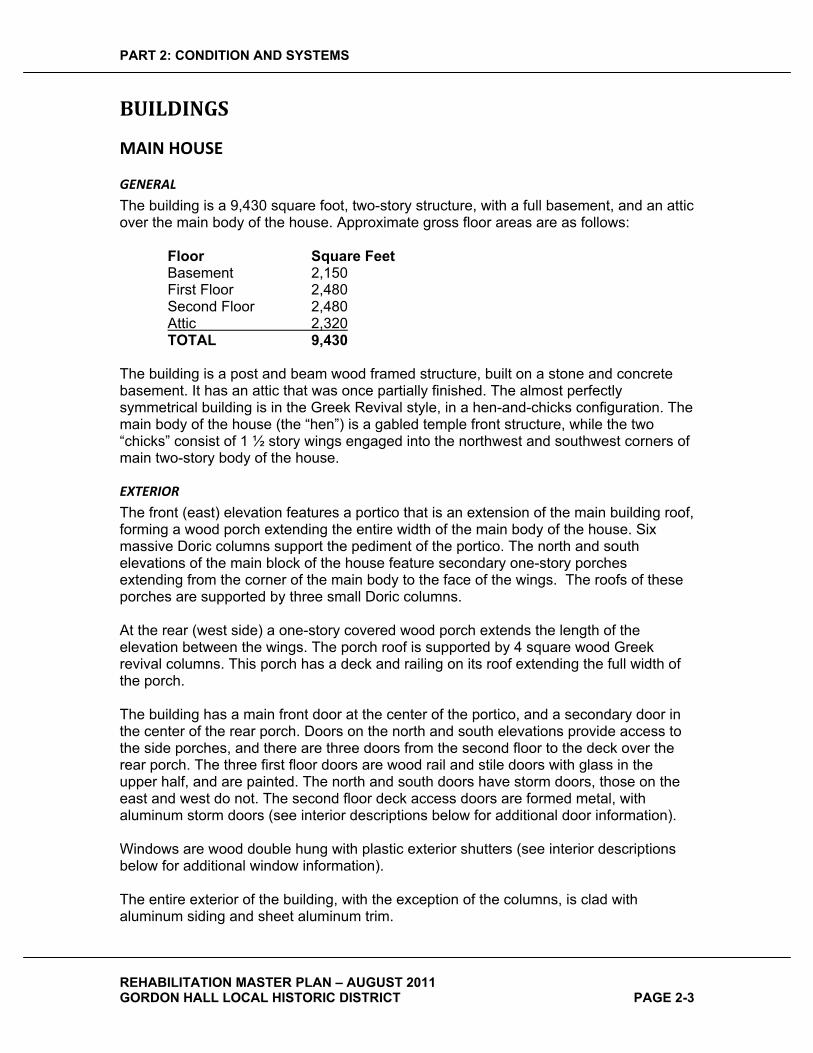
The building is a 9,430 square foot, two-story structure, with a full basement, and an attic over the main body of the house. Approximate gross floor areas are as follows:
Floor Square Feet Basement 2,150 First Floor 2,480 Second Floor 2,480 Attic 2,320TOTAL 9,430
The building is a post and beam wood framed structure, built on a stone and concrete basement. It has an attic that was once partially finished. The almost perfectly symmetrical building is in the Greek Revival style, in a hen-and-chicks configuration. The main body of the house (the “hen”) is a gabled temple front structure, while the two “chicks” consist of 1 ½ story wings engaged into the northwest and southwest corners of main two-story body of the house.
EXTERIOR�
The front (east) elevation features a portico that is an extension of the main building roof, forming a wood porch extending the entire width of the main body of the house. Six massive Doric columns support the pediment of the portico. The north and south elevations of the main block of the house feature secondary one-story porches extending from the corner of the main body to the face of the wings. The roofs of these porches are supported by three small Doric columns.
At the rear (west side) a one-story covered wood porch extends the length of the elevation between the wings. The porch roof is supported by 4 square wood Greek revival columns. This porch has a deck and railing on its roof extending the full width of the porch.
The building has a main front door at the center of the portico, and a secondary door in the center of the rear porch. Doors on the north and south elevations provide access to the side porches, and there are three doors from the second floor to the deck over the rear porch. The three first floor doors are wood rail and stile doors with glass in the upper half, and are painted. The north and south doors have storm doors, those on the east and west do not. The second floor deck access doors are formed metal, with aluminum storm doors (see interior descriptions below for additional door information).
Windows are wood double hung with plastic exterior shutters (see interior descriptions below for additional window information).
The entire exterior of the building, with the exception of the columns, is clad with aluminum siding and sheet aluminum trim.

PART 2: CONDITION AND SYSTEMS
REHABILITATION MASTER PLAN – AUGUST 2011 GORDON HALL LOCAL HISTORIC DISTRICT PAGE 2-4
ROOFS�
The sloped roofs are asphalt shingles. Flashings are largely concealed by aluminum siding. Chimney flashings are aluminum, attached to chimneys with screws and sealed with sealant. Rear dormer roofs are very low sloped, and are clad with copper. The deck over the rear porch is roofed with flat-lock seamed galvanized sheets, coated with a liquid applied membrane that is very old and deteriorated.
WATER�MANAGEMENT�
The building currently has only limited gutters. One is located over the rear steps, and one is located over each dormer window. There are no functional downspouts. There is evidence of previous gutters and downspouts, at locations where straps that supported them survive, and where trim was cut away to accommodate downspouts.
FOUNDATIONS�
Exposed exterior portions of building and porch foundations are generally stone, except at the northwest wing and west porch, where they are concrete. The amount of exposed foundation varies from approximately 6” to 24”.
INTERIOR�
Interior consists of a basement under all portions of the house, first and second floors, and an attic. The basement is unfinished, as is the attic. The first and second floors are nearly identical in plan and detail, each containing two apartments.
The interior of the building has been much modified over its life, to the point that very little historic fabric remains, and the original interior spatial configuration has been completely obliterated, save for the three-bay structural arrangement.
BASEMENT�
The main block and the two wings have full basements under them. The four porches have crawl spaces under them. Basement walls are primarily constructed of uncut stone. However, the northwest wing basement walls are constructed of reinforced concrete, and are clad on the interior with foil-faced insulation. Some basement spaces have been excavated deeper than their original configuration, and their walls show concrete underpinning. All basement floors are concrete.
The basement under the main block of the house is divided into two spaces, the north portion occupying approximately two-thirds of the building footprint, and the south encompassing the remaining one-third. Each of the basement spaces under the main block has a basement window in the east wall that provides access to the crawl space under the portico. A stone foundation wall separates the two basement spaces of the main block of the house.
The larger northerly space contains several columns (some brick, some steel) that support the first floor above, as well as two stairways that provide access from the first floor. The west stair is enclosed with drywall, and has a door at the bottom. The building’s boiler and water heater are located in this space, as are some electrical distribution panels. The stone walls of this space are nearly full height, with 6” to 8” of underpinning around the perimeter as evidenced by curbs surrounding the space.
PART 2: CONDITION AND SYSTEMS
REHABILITATION MASTER PLAN – AUGUST 2011 GORDON HALL LOCAL HISTORIC DISTRICT PAGE 2-5
The smaller south basement contains one steel column, and is empty except for some shelving along the south and west walls. The south wall of the south basement has been underpinned with concrete, as has the west wall. The north wall (shared with the basement to the north) has stone for its full height. The east wall is partially underpinned by a low horizontal ledge approximately 16” high and 5’ deep.
The small southwest wing’s basement is stone, with two columns supporting the floor above. It has a cellar door in the west wall providing access from the exterior. It has no other openings to the exterior. A window in the east wall provides access to the crawl space under the south porch. This opening has a concrete infill under the sill of the window. The east wall has a brick portion that appears to be a remnant of an earlier fireplace.
The basement of the northwest wing is of much newer construction, being built of concrete. It has modern sliding aluminum windows in the west and north walls. It has a sump pit and pump, well pressure tank, water filter, cast cement laundry sink, abandoned dryer vents, and contains the building’s electrical service entry.
Ceiling in the basements appear to be 3/8” gypsum wallboard. The exact nature of the material is not known, and further assessment is recommended, especially with respect to hazardous material content.
FIRST�AND�SECOND�FLOORS�
Gordon Hall as it stands today is essentially configured as a four-unit mid-20th century apartment building. The first and second floors each have a north and south apartment organized around two central stairways at the center of the east and west sides of the building.
STAIRWAYS�
The east stairway is accessed from the historic the “front door” of the building and provides access to second floor apartments. It is accessed through a wood and glass front door with glass sidelights centered on the east portico, which opens into a small vestibule. An inner wood and glass door with sidelights leads to the stairway that is open to the first and second floors. The front doors to the two first floor apartments are located on the north and south walls of this stairway. A third door leads to the basement stairs. The stairs to the second floor are open with painted and stained wood railings. At the second floor, the doors to the two apartments are on the north and south walls of the stairway. A third door leads to the attic.
The west stairway is accessed from the “rear door” to the building, but with easy access to parking, this may have been the most often-used door and stairway. A wood and glass door with glass sidelights at the center of the west porch provides access to the west stairway, which is open to the first and second floors. The rear doors to the first floor apartments are located on the north and south walls of this stairway. The stairs to the second floor are open with painted and stained wood railings. A stair leads to the basement from the first floor and is open at the top, but is enclosed by walls and a door at the basement level. Just below the second floor is a landing with a door leading to the sitting deck on the roof of the west porch. At the second floor, the rear doors to the two apartments are also located on the north and south walls of the stairway.

PART 2: CONDITION AND SYSTEMS
REHABILITATION MASTER PLAN – AUGUST 2011 GORDON HALL LOCAL HISTORIC DISTRICT PAGE 2-6
Floors(including stairs)
Carpeted. Vinyl asbestos tile is found immediately under the carpet.
Walls Painted plaster on gypsum lath.
Trim(doors, windows, base)
Painted molded wood trim.
Outside Entry Doors (first floor – east and west)
Wood rail and stile, paneled; painted; single glass light in upper half. Fixed single-glazed sidelights and transoms in wood frames with wood muntins. Sidelights have wood panels at bottom.
Sitting Deck Door(second floor – west stair only)
Formed metal paneled doors single glass light in upper half. Painted. Aluminum storm door.
Inner Vestibule Door (east only)
Wood rail and stile, paneled; painted; single glass light in upper half. Fixed single-glazed sidelights and transoms in wood frames with wood muntins.
Apartment Doors Stained wood flush doors.
Windows First floor: Door sidelights and transoms – See door descriptions above. Second floor: Wood double hung, with sash weights; painted. Exterior aluminum combination storm windows.
Lighting Contemporary ceiling mounted incandescent.
Stair Railings and Balusters Painted and stained wood.
APARTMENTS�–�GENERAL�
All four apartments are essentially identical, the north and south units being mirror images of one another. They are modern two bedroom units with one bath, a combined living and dining area that is open to a small kitchen. The first floor apartments are all on the same level; at second floor units, the bedroom and bathroom located in the wing are four steps lower than the rest of the apartment. Each apartment has a fireplace with a painted wood mantel. Apartments are heated with wall-mounted electric radiant heating panels.
LIVING�ROOMS�
All four living rooms are essentially identical in size, configuration, features and finishes. All living rooms have fireplaces with a painted wood mantel with non-original fire screens. Fireplace hearths are of a variety of materials. The living rooms are contiguous with the adjacent dining rooms.
Floors Carpet over linoleum.
Walls Painted plaster.
Trim Painted molded wood trim.

PART 2: CONDITION AND SYSTEMS
REHABILITATION MASTER PLAN – AUGUST 2011 GORDON HALL LOCAL HISTORIC DISTRICT PAGE 2-7
(doors, windows, base)
Fireplace firebox Brick
Fireplace mantel and surround
Painted wood
Doors Stained wood flush doors.
Windows Wood double hung, with sash weights; painted. Exterior aluminum combination storm windows.
Lighting None
DINING�ROOMS�
All four dining rooms are essentially identical in size, configuration, features and finishes, except that the first floor living rooms have doors providing access to the north or south porches. The dining rooms are continuous with the adjacent living rooms, and are open to the adjacent kitchens.
Floors Carpet over linoleum.
Walls Painted plaster.
Trim(doors, windows, base)
Painted molded wood trim.
Doors Door to exterior (first floor only): Painted wood rail and stile, paneled, and with upper half of door glazed. Wood storm door (north apartment); aluminum storm door (south apartment).
Windows Wood double hung, with sash weights; painted. Exterior aluminum combination storm windows.
Lighting Ceiling mounted contemporary incandescent light or fan/light. Some reproduction early 20th century fixtures at first floor.
KITCHENS�
All four kitchens are essentially identical in size, configuration, features and finishes. Kitchens have a range, refrigerator, single bowl stainless steel sink, natural wood upper and lower cabinets, and plastic laminate countertops. A door in the west walls of the kitchens provides access to apartment from the rear stairway. Kitchens are open to the adjacent dining rooms. A small closet is located in each kitchen.
Floors Sheet vinyl
Walls Painted plaster.
Trim(doors, windows, base)
Painted molded wood trim.

PART 2: CONDITION AND SYSTEMS
REHABILITATION MASTER PLAN – AUGUST 2011 GORDON HALL LOCAL HISTORIC DISTRICT PAGE 2-8
Door Stained wood flush. Closet door: Flush wood; some painted, some stained.
Windows None
Lighting Contemporary. Varies: Ceiling mounted incandescent or fluorescent.
HALLWAYS�
A small hallway leads from the dining room toward the west in each apartment. It links to the first bedroom, and then turns to provide access to the bathroom and bedroom, both located in the wing. There is a closet in the hallway across from the bathroom. At second floor apartments the hallway has four steps leading down to the bedroom and bathroom located in the wings, which are 28” lower than the remainder of the second floor. In addition, second floor apartments have doors at the west end of the corridor that provide access to the deck over the rear porch.
Floors Carpet over linoleum.
Walls Painted plaster.
Trim(doors, windows, base)
Painted molded wood trim.
Doors Doors to bedrooms: See bedroom descriptions. Closet door: Pair - flush wood, stained or painted. Door to deck (second floor only): Painted formed metal, paneled, with upper half of door glazed. Aluminum storm door.
Windows None.
Lighting Contemporary ceiling mounted incandescent. Some reproduction early 20th century fixtures at first floor.
BATHROOMS�
All four bathrooms are essentially identical in size, configuration, features and finishes. Bathrooms have a bathtub with shower, porcelain sink in a circa 1970’s prefabricated vanity with cast synthetic counter, and water closet. Each has a linen closet just inside the bathroom door. Some have surface wall mounted medicine cabinets.
Floors Ceramic tile
Walls Painted plaster; ceramic tub surround. Wallpaper at some bathrooms.
Trim(doors, windows, base)
Painted molded wood trim.
Doors Bathroom Door: Wood flush door, stained. Linen Closet Door: Wood flush door, painted.
PART 2: CONDITION AND SYSTEMS
REHABILITATION MASTER PLAN – AUGUST 2011 GORDON HALL LOCAL HISTORIC DISTRICT PAGE 2-9
Windows Wood double hung, painted; spring balances. Exterior aluminum combination storm windows.
Lighting Contemporary wall mounted sconces or over mirror light fixtures.Traditional styled sconces at first floor.
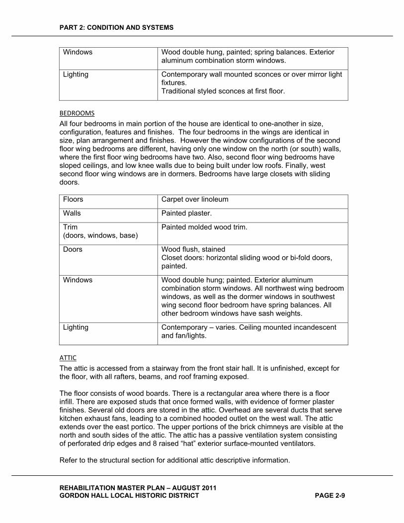
BEDROOMS�
All four bedrooms in main portion of the house are identical to one-another in size, configuration, features and finishes. The four bedrooms in the wings are identical in size, plan arrangement and finishes. However the window configurations of the second floor wing bedrooms are different, having only one window on the north (or south) walls, where the first floor wing bedrooms have two. Also, second floor wing bedrooms have sloped ceilings, and low knee walls due to being built under low roofs. Finally, west second floor wing windows are in dormers. Bedrooms have large closets with sliding doors.
Floors Carpet over linoleum
Walls Painted plaster.
Trim(doors, windows, base)
Painted molded wood trim.
Doors Wood flush, stained Closet doors: horizontal sliding wood or bi-fold doors, painted.
Windows Wood double hung; painted. Exterior aluminum combination storm windows. All northwest wing bedroom windows, as well as the dormer windows in southwest wing second floor bedroom have spring balances. All other bedroom windows have sash weights.
Lighting Contemporary – varies. Ceiling mounted incandescent and fan/lights.
ATTIC�
The attic is accessed from a stairway from the front stair hall. It is unfinished, except for the floor, with all rafters, beams, and roof framing exposed.
The floor consists of wood boards. There is a rectangular area where there is a floor infill. There are exposed studs that once formed walls, with evidence of former plaster finishes. Several old doors are stored in the attic. Overhead are several ducts that serve kitchen exhaust fans, leading to a combined hooded outlet on the west wall. The attic extends over the east portico. The upper portions of the brick chimneys are visible at the north and south sides of the attic. The attic has a passive ventilation system consisting of perforated drip edges and 8 raised “hat” exterior surface-mounted ventilators.
Refer to the structural section for additional attic descriptive information.

PART 2: CONDITION AND SYSTEMS
REHABILITATION MASTER PLAN – AUGUST 2011 GORDON HALL LOCAL HISTORIC DISTRICT PAGE 2-10
Floors 1” X 6” wood boards, unfinished.
Walls Remnant of plaster finish at west exterior wall. Only bare studs at other former walls (consistent with an attic room shown on HABS Drawings).
Trim(doors, windows, base)
Wood painted base at west exterior wall. Other walls - none.
Doors None
Windows Three painted wood double hung windows. Utilitarian windows, without sash weights.
Lighting Porcelain socket bare bulbs with pull chains.
Ceiling Height Sloped, varies
�
OUTBUILDINGS�Existing outbuildings consist of a one-story 19th century Store House with a basement connected to a contemporary utilitarian four-car garage is located to the northwest of the main house.
STORE�HOUSE�
EXTERIOR�
The Store House is a white painted brick masonry structure on a stone foundation, with a wood-framed gabled asphalt shingle roof. Sills in masonry openings on the north side are wood timbers. At the south side, the sill is concrete, formed flush with the brick.
INTERIOR�
The Store House consists of an upper level and deep basement. Its first floor elevated approximately 2’ above grade. The upper level, in addition to the features described below, features painted wood shelving along the north and east walls. The floor features a hatch to the basement at the south end of the space. A low wood wall surrounds a hatch to the basement on two sides.
Ceiling: Upper level: Wood boards, painted Basement: Exposed joists.
Walls: Plaster, applied directly to brick, painted Floors: Upper level: 1 X tongue and groove wood boards,
varying widths, painted. Hinged two part wood board hatch with finger lifting ring in floor to provide access to basement, painted. Basement: Dirt
Trim: Wood, painted; simple flat profiles. Windows: Double hung, utilitarian, no sash weights or balances;
simple linear sticking profiles (not molded).
PART 2: CONDITION AND SYSTEMS
REHABILITATION MASTER PLAN – AUGUST 2011 GORDON HALL LOCAL HISTORIC DISTRICT PAGE 2-11
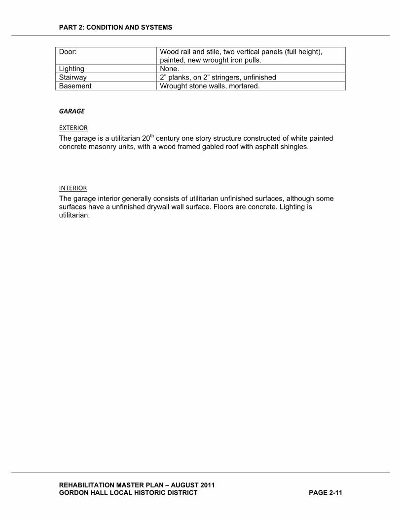
Door: Wood rail and stile, two vertical panels (full height), painted, new wrought iron pulls.
Lighting None. Stairway 2” planks, on 2” stringers, unfinished Basement Wrought stone walls, mortared.
GARAGE�
EXTERIOR�
The garage is a utilitarian 20th century one story structure constructed of white painted concrete masonry units, with a wood framed gabled roof with asphalt shingles.
INTERIOR�
The garage interior generally consists of utilitarian unfinished surfaces, although some surfaces have a unfinished drywall wall surface. Floors are concrete. Lighting is utilitarian.
PART 2: CONDITION AND SYSTEMS
REHABILITATION MASTER PLAN – AUGUST 2011 GORDON HALL LOCAL HISTORIC DISTRICT PAGE 2-12
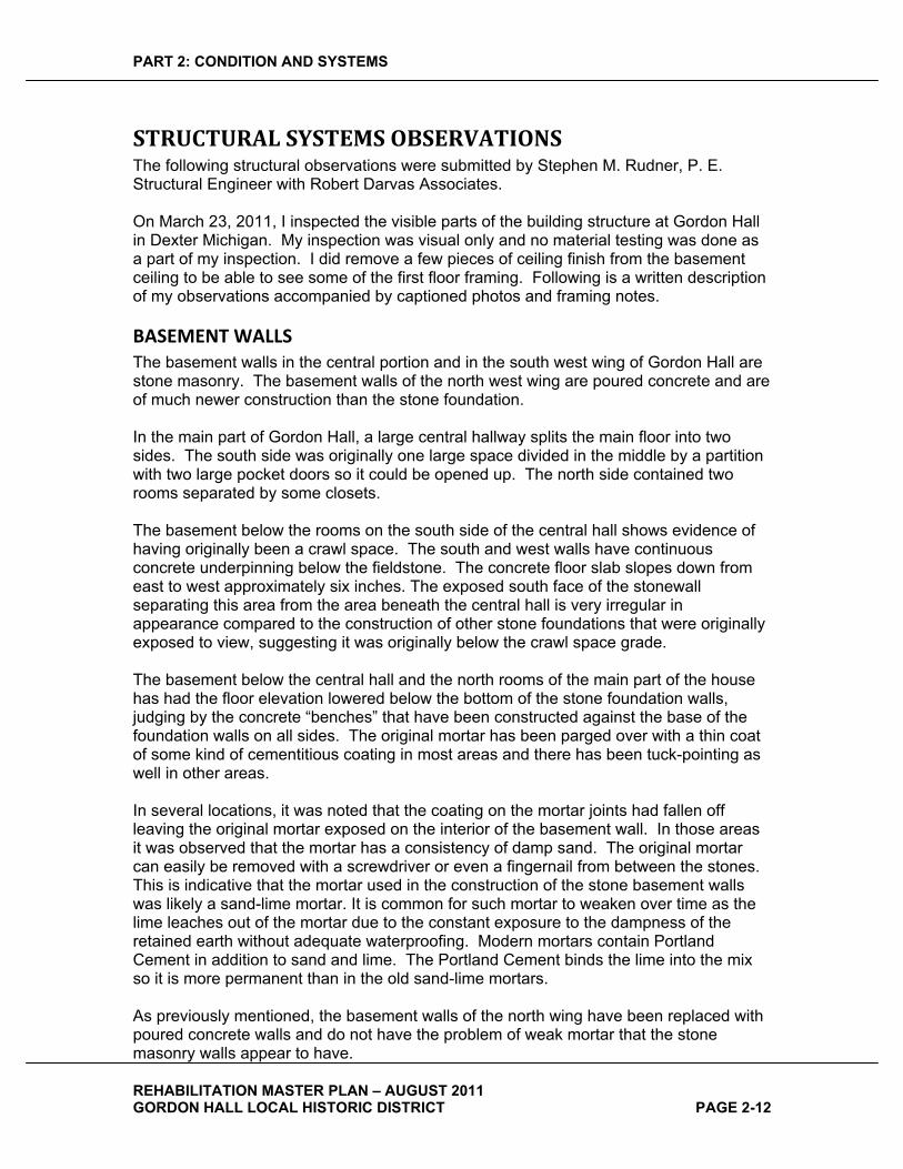
STRUCTURAL�SYSTEMS�OBSERVATIONS�The following structural observations were submitted by Stephen M. Rudner, P. E. Structural Engineer with Robert Darvas Associates.
On March 23, 2011, I inspected the visible parts of the building structure at Gordon Hall in Dexter Michigan. My inspection was visual only and no material testing was done as a part of my inspection. I did remove a few pieces of ceiling finish from the basement ceiling to be able to see some of the first floor framing. Following is a written description of my observations accompanied by captioned photos and framing notes.
BASEMENT�WALLS�The basement walls in the central portion and in the south west wing of Gordon Hall are stone masonry. The basement walls of the north west wing are poured concrete and are of much newer construction than the stone foundation.
In the main part of Gordon Hall, a large central hallway splits the main floor into two sides. The south side was originally one large space divided in the middle by a partition with two large pocket doors so it could be opened up. The north side contained two rooms separated by some closets.
The basement below the rooms on the south side of the central hall shows evidence of having originally been a crawl space. The south and west walls have continuous concrete underpinning below the fieldstone. The concrete floor slab slopes down from east to west approximately six inches. The exposed south face of the stonewall separating this area from the area beneath the central hall is very irregular in appearance compared to the construction of other stone foundations that were originally exposed to view, suggesting it was originally below the crawl space grade.
The basement below the central hall and the north rooms of the main part of the house has had the floor elevation lowered below the bottom of the stone foundation walls, judging by the concrete “benches” that have been constructed against the base of the foundation walls on all sides. The original mortar has been parged over with a thin coat of some kind of cementitious coating in most areas and there has been tuck-pointing as well in other areas.
In several locations, it was noted that the coating on the mortar joints had fallen off leaving the original mortar exposed on the interior of the basement wall. In those areas it was observed that the mortar has a consistency of damp sand. The original mortar can easily be removed with a screwdriver or even a fingernail from between the stones. This is indicative that the mortar used in the construction of the stone basement walls was likely a sand-lime mortar. It is common for such mortar to weaken over time as the lime leaches out of the mortar due to the constant exposure to the dampness of the retained earth without adequate waterproofing. Modern mortars contain Portland Cement in addition to sand and lime. The Portland Cement binds the lime into the mix so it is more permanent than in the old sand-lime mortars.
As previously mentioned, the basement walls of the north wing have been replaced with poured concrete walls and do not have the problem of weak mortar that the stone masonry walls appear to have.

PART 2: CONDITION AND SYSTEMS
REHABILITATION MASTER PLAN – AUGUST 2011 GORDON HALL LOCAL HISTORIC DISTRICT PAGE 2-13
There are two chimneys of the original four remaining. These two chimneys are constructed of brick masonry all the way to the foundation although they are abutting the stone foundation wall on one face. Both of the brick chimneys have cracks where they abut the stone foundation wall. Along the west face of the southwest chimney, the crack meanders away from the interface between the stone and the brick and passes through numerous bricks and brick joints.
On the exterior, it was noted that the east foundation wall of the south wing appears to have been encapsulated in poured concrete.
FIRST�FLOOR�FRAMING�The majority of the first floor framing is concealed by a ceiling. The ceiling material is a thin cement board type of product that should be tested to determine if it contains asbestos. I was able to observe small areas of the first floor framing by removing a few pieces of the ceiling material and also by observing the framing in areas where the ceiling material had either been removed or had fallen off. The size, spacing, and direction of span of the framing I was able to observe are shown on the attached sketch. I did note that in numerous locations where I was able to observe the framing, electricians and plumbers had unfortunately cut holes and notches in locations where they weakened the structure, and where they are not supposed to be located by code. In my limited observation of the first floor framing I did not observe any significant deterioration due to rot or insects however I was not really able to see very much of that structure at all.
The first floor structure observed in the central and south wings are rough sawn timber with some mortise and tenon joinery. The north wing has newer floor joists that are surfaced on four sides.
The original first floor structure has been modified at several locations. The original basement stair opening has been in-filled; and a steel beam plus two pipe columns have been placed beside the opening to support the ends of the original joists which do not extend to the foundation wall. Two new stair openings have been introduced which required cutting and re-supporting the first floor framing around the new openings. The holes left by removal of two of the four chimneys have been in-filled and floored over. Numerous steel pipe columns have been added which are likely non-original. Pipe column locations are shown on the first floor framing sketch accompanying this report.
PORCH�FLOOR�FRAMING�The framing of the east and south porches could be observed through openings into their respective crawl spaces. It was noted that there appear to be concrete beams supporting the timber porch floor joists. This is a very unusual detail to find in a building of this vintage and one must wonder if these concrete beams are original.
PORCH�COLUMNS�The porch columns are made of wood staves and are likely structural as well as decorative. Contemporary versions of this type of hollow wood column are produced by several manufacturers and can be used as structural supports alone, or they can be augmented by having timber or steel pipe columns inside the hollow column to increase
PART 2: CONDITION AND SYSTEMS
REHABILITATION MASTER PLAN – AUGUST 2011 GORDON HALL LOCAL HISTORIC DISTRICT PAGE 2-14
their capacity. I was unable to see the interior of the columns but my opinion is that they are likely hollow and that the shell of the column is the structure. Several of the columns exhibited signs of deterioration such as cupping staves, and peeling paint, as well as signs of distress at the very bottom of the shaft where the wood end grain is easily exposed to moisture from rain and snowmelt. The contemporary versions of these type of hollow wood columns feature venting base and cap details to promote air flow through the interior of the column so they dry out after becoming wet.
SECOND�FLOOR�FRAMING�None of the second floor framing could be observed due to building finishes. Measurements were taken in the stairwell which indicate the framing depth is approximately 9.5 inches, however this was in an area of newer framing which may not be indicative of the depth of the original framing. The second floor framing of the two wings is set at a different height than the floor of the main part of the house requiring stairs between the second floor area of the main house and the wings.
ATTIC�FLOOR�FRAMING�Very little of the attic floor framing could be observed. Near the east gable end wall, the attic floor joists could be observed through a slot in the floor. These joists appear to run east-west, which is opposite to the first floor joists. The size and spacing of the floor joists was random. I observed 2x8’s and 3x8’s at 14” to 24” spacing. The joists likely span to interior partition walls and it is likely the numerous non-original beams above the attic floor are suspending the attic floor joists at locations where partitions were removed or re-located. The east gable end wall must be supported by a beam or beams spanning between the porch columns however, this beam or beams was/were not able to be observed. When you are standing near the east gable end wall you are out over the front porch. No access into the attics of the two wings was seen, if indeed there are attics, and it is unlikely there are attic floors in these areas.
ROOF�FRAMING�The roof framing of the main part of the house could be observed but not the roof framing of the wings. The sloped rafters are rough sawn 2x6’s at 18”c/c spacing. Many of the rafters have a second member sistered high on one side as if to straighten the line of the tops of the rafters prior to installing the roof boards. There are collar ties at all rafter pairs except at the skylight area where the original skylight opening has been filled in with new framing. The rafters span north-south and are supported on two beams on each side of the ridge. The rafters are interrupted by the upper beam that is a 7” x 7” timber. The rafters plug into this beam with mortise and tenon joinery. The lower beam on each side sits below the rafters and the rafters span continuous across the top of this beam. These lower beams are 6” x 6” timbers. Both upper and lower beams are supported on inclined columns that originally occurred at the locations of second floor partitions. Some of these inclined columns now are supported on non-original beams that were added above the attic floor when partitions were re-located below. Some but not all of these added beams are shown on the 1950 University of Michigan drawings, specifically on sheet A-7.
Water staining in the attic indicates past roof leaks however, the attic was dry during my visit and no wood rot was observed.
PART 2: CONDITION AND SYSTEMS
REHABILITATION MASTER PLAN – AUGUST 2011 GORDON HALL LOCAL HISTORIC DISTRICT PAGE 2-15
The above observations and my enclosed captioned photos and framing sketches represent my observations to date. Recommendations on the needed revisions to the floor framing and/or strengthening follow based upon the decision that the use of the first and second floor will be public spaces. The basement and attic levels are assumed to be unoccupied except for mechanical equipment and service personnel.
PART 2: CONDITION AND SYSTEMS
REHABILITATION MASTER PLAN – AUGUST 2011 GORDON HALL LOCAL HISTORIC DISTRICT PAGE 2-16
MECHANICAL�SYSTEMS�
EXISTING�HVAC�SYSTEMS�The Building currently has an “abandoned in place”, fuel oil fired “American Standard” W-2012 18-13 series hot water heating boiler. The latest boiler tag located near the nameplate indicates the boiler was last serviced on 09-05-80. Based on the tag it is safe to conclude that the boiler hasn’t been in operation since approximately 1982. The abandoned in place, heating hot water distribution systems consists of several zone pumps with abandoned heating hot water supply piping and a common heating hot water return loop tied into the boiler. The boiler systems more than likely served finned tube radiation & convectors with manual control valves on each floor of the building that were removed when the boiler was deactivated. The abandoned boiler is vented with a 14” diameter flue tied into the building chimney. The boiler and all related equipment appears to be in very poor condition. Existing fuel oil fill piping appears to still be in place extended and abandoned at the outside wall
The copper heating hot water supply and return piping in the building appears to be in fair condition, however because of the age of the piping it is suspected that the piping has a build-up of scale with-in. Suspicious pipe insulation in fair / poor condition was observed where piping is exposed. No natural gas piping was observed in any areas of the building.
Throughout the entire building including the apartment units, basement and all other common areas, multiple electric radiant panel heaters currently heat the building. Each room area is controlled by a zone thermostat specific to the heaters located in the space. Multiple heating zones exist in each apartment unit and common areas. It is assumed the heaters and all other electrical accessories and controls were installed when the boilers were de-activated. The electric heaters appear to be functioning and in fair condition, however due to their age, location and size it is doubtful they are providing the required heat output to overcome the heat loss in the existing structure.
A residential type kitchen exhaust hood is installed in each apartment unit’s kitchenette over the cooking range. The hoods have a built-in exhaust fan with exhaust ducts extending up thru walls up into the attic space with each exhaust duct connected to a common exhaust plenum attached to a louver located on a gable end. Mechanical make-up air or ventilation air is not provided for any areas of the building and toilet room exhaust fans do not exist.
EXISTING�PLUMBING�SYSTEMS�The domestic water service is from a well with a 1” line size feeding into a hydro-pneumatic storage tank. The 1” line supplies domestic cold water thru-out the building. One (1) “Lochinvar HSP 18-082” 82 gallon, 18 KW at 240 volt / 1 phase electric water heater in good condition, without re-circulation, provides domestic hot water for the entire building. A combination of galvanized and copper piping currently provides water distribution for the building. The piping appears to be in fair condition, however because of the age of the galvanized piping, it is suspected that the piping is corroded on the inside with a build-up of scale with-in. Suspicious pipe insulation in fair condition was observed where piping is exposed. Sanitary waste and vent piping is cast iron with

PART 2: CONDITION AND SYSTEMS
REHABILITATION MASTER PLAN – AUGUST 2011 GORDON HALL LOCAL HISTORIC DISTRICT PAGE 2-17
minimal PVC .Two (2) cast iron sanitary leads exit on each side of the house. It is assumed that both leads extend to a common septic field serving the entire building. Repairs to sanitary and vent piping were observed. The condition of the sanitary drainage piping is suspect because of its age.
The apartment units on all floors have kitchenettes equipped with typical residential type warming kitchen appliances. The stainless steel sinks have disposers under the sink. Hot water is provided from the building’s hot water system from the single water heater located in the basement. The kitchens appear to be fully functional and are in fair / poor condition with dated plumbing fixtures. Piping concerns listed in the first paragraph also apply for all concealed piping mains.
The apartment units on all floors have complete bathrooms with bathtubs and shower heads. All the lavatories, tank type water closets bathtubs and related trim appear to be dated fixtures and trim in fair / poor condition. The existing fixture installation does not comply with current A.D.A. standards in any parts of the building. Piping concerns listed in the first paragraph also apply for all concealed piping.
PART 2: CONDITION AND SYSTEMS
REHABILITATION MASTER PLAN – AUGUST 2011 GORDON HALL LOCAL HISTORIC DISTRICT PAGE 2-18
ELECTRICAL�SYSTEMS�On March 23, 2011 a site visit of Gordon Hall was performed by TAC Associates, LLC to survey the existing condition of the electrical systems in the building.
ELECTRIC�SERVICE�AND�POWER�DISTRIBUTION�The existing electric service to the building is an underground 240 / 120 volt, single phase, three wire DTE Energy service that appears to originate from a pad mounted transformer located on the north side of the property, on the adjacent Cedars of Dexter property. The incoming service feeders to the site terminate at an exterior steel metal “wireway” with five (5) DTE Energy utility meters mounted on an independent wooden structure approximately 3’-0” away from the house, just outside of the basement laundry room area. The service feeders consist of a single 3-1/2” conduit with 3 conductors. The exact size of the service conductors was not able to be determined during our visual survey; however based on their physical size it appears that the conductors are 500 kcmil and assumed to be copper.
The 500kcmil incoming service feeders are tapped with AWG #2 conductors for each of the four (4) DTE Energy utility meters serving the apartments, and with AWG #2/0 copper conductors for the single DTE Energy utility meter that serves the “house” loads. All of the taps are made using a Burndy tap kit. The AWG #2 and #2/0 copper conductors are then routed from the utility meters in a single 3-1/2” steel conduit into the Basement Laundry room of the house.
The four (4) DTE Energy utility meters each serve one of the existing apartment units in the house, with the fifth DTE Energy utility meter serving the common areas of the house, and referred to as the “house” meter.
The single 3-1/2” steel conduit enters the Basement Laundry room near the location of the well pressure tank, and is routed along the outside wall of the Basement to a surface mounted steel “wireway”. The main disconnect switches for the building are mounted at this “wireway”, and consists of four (4) 100A-2P circuit breaker main switches for each of the four (4) apartment units, and one (1) 150A-2P circuit breaker for the “house” loads.
The electric service “electrode grounding” for the service occurs at the 150A-2P main circuit breaker serving the “house” loads only; the location of the grounding electrode (aka “ground rod”) and the point of termination of the copper electrode grounding conductor from the main circuit breaker was not able to be visually indentified during the survey of the building and site. Since the water source for the building is from a well which has been recently replaced, it is expected that the grounding electrode for the building is a ground rod driven somewhere near the incoming electric service.
The electric service is distributed from the main switches noted to lighting panels located throughout the building as follows. Each of the four (4) apartment units have a 100 ampere main lugs only, 240 /120 volt single phase three wire circuit breaker type lighting panel located in a closet just off the unit Kitchen.
The “house” main circuit breaker feeds a 200 ampere main lugs only, 240 / 120 volt, single phase, three wire circuit breaker type lighting panel located at the Basement across from the existing boiler, and in this report is referred to as panel “LP-HA”. A
PART 2: CONDITION AND SYSTEMS
REHABILITATION MASTER PLAN – AUGUST 2011 GORDON HALL LOCAL HISTORIC DISTRICT PAGE 2-19
second screw-base, fuse type 240 / 120 volt, single phase, three wire lighting panel is mounted next to this panel, and is fed from a 60 ampere, 2 pole circuit breaker in a “sub-panel” fed type of arrangement. It appears that the screw-base fuse type lighting panel is an original panel from when the house was a single family residence, and appears to have been re-fed in the existing “sub-panel” configuration when the conversion to a multi-family residence was performed in 1950.
The existing Garage located on the site just west of the Milk House is fed from a 30 ampere, 240 / 120 volt, single phase circuit breaker in house lighting panel “LP-HA”.
All of the feeders serving the noted apartment and “house” lighting panels appear to be installed in metal raceways (aka “conduit”); however none of the feeders include a separate equipment grounding conductor to the panels. It appears that the system is utilizing the raceway as the equipment grounding path.
INTERIOR�LIGHTINGThe existing lighting is a mixture of incandescent and fluorescent lighting fixtures, all of which appear to date from the renovation work that occurred in 1950 to create the multi-family residences and the associated maintenance of the facility over the fifty (50) years of operation as a multi-family residence. The fluorescent lighting appears to be limited to the Basement Laundry room and the Kitchens in the four (4) apartment units.
The existing apartment unit on the first floor, north side, has recently upgraded the lighting to a decorative type of incandescent lighting that is unique among the four (4) existing apartment units, and was performed after the building was acquired by the Dexter Area Historical Society. The lighting in this unit consists of residential grade decorative surface and pendant mounted incandescent fixtures that were purchased from a local home improvement store and installed by the Historical Society.
In addition to the lighting noted above, ceiling fans with light kits are installed in all of the apartment units with the exception of the first floor, north side unit. The ceiling fans appear to date from a period after the original conversion of the building to a multi-family residence; however the exact period of the ceiling fan installation was not able to be determined.
EMERGENCY�AND�EXIT�LIGHTINGEmergency and exit lighting does not currently exist in the facility.
EXTERIOR�LIGHTINGOutdoor lighting is mostly building mounted with either recess mounted or surface mounted incandescent lighting fixtures located at the ceiling of each of the porches. In addition to the ceiling mounted lighting fixtures noted, there is a single decorative wall mounted “carriage-type” light fixtures with an American eagle motif located high above the door, just below the second floor window, over the entry door at the east porch.
A surface wall mounted incandescent globe and guard type light fixture (aka “jelly jar”) is located at the exterior door to the second floor balcony.

PART 2: CONDITION AND SYSTEMS
REHABILITATION MASTER PLAN – AUGUST 2011 GORDON HALL LOCAL HISTORIC DISTRICT PAGE 2-20
A single pole mounted, approximately 15’-0” high light fixture is located at the north side of the building near the parking area. The fixture appears to be an HID type fixture, with either a high pressure sodium or metal halide lamp source; however during our field investigation we were not able to verify that this fixture is operational, or what the exact type of light source is used in the fixture.
A bare lamp holder type fixture is installed under the soffit of the garage on the south side of the garage, and provides exterior lighting along the south side of the garage.
BRANCH�WIRING�AND�DEVICESThe majority of the branch circuit wiring serving the “house” loads and at least one of the apartment units appears to be separate conductors installed in a metal raceway (aka “conduit”). The wiring all appears to be copper, with modern insulation material on the vast majority of the installed wiring. Only a few existing “house” branch circuits fed from the existing screw-base fuse lighting panel in the Basement utilize cloth covered wiring.
It should be noted that there are a few observed cases where type NM, non-metallic sheathed cable (aka “Romex”) is installed for some “house” circuits, but this appears to be limited to two (2) branch circuits fed from the Basement “house” lighting panel, one of which is the recently installed well pump.
The existing wiring methods used in the apartment units varies, with a mixture of some circuits served with separate conductors in conduit, and others using type NM (“romex”) wiring. In several of the existing apartment units the existing branch circuit wiring serving the electric range is cloth covered aluminum wiring. These electric range circuits were the only cases where aluminum conductors were readily observed to be installed in the building.
For the existing “house” branch circuits there appears to be separate equipment grounding conductors installed for only some of the circuits, which corresponds to the observed case that not all of the duplex receptacles installed in the common areas of the building, including the Basement are grounding type.
For the apartment units it appears that the majority of the branch circuits served from the panels includes a separate equipment grounding conductor; however there were cases in the apartment units where non-grounding type duplex receptacles were observed to be installed.
Most of the wiring installed in the Attic is cloth covered “Romex”, and appears to date to when the building was a single family residence.
There is no consistency in the color coding scheme used for the wiring serving select loads, including the electric radiant heating panels.
All of the environmental space heating in the facility is provided by electric resistive radiant heating panels. The radiant panels are controlled by zone specific thermostats. Refer to the mechanical section of the report for additional information regarding the locations and control of the existing electric radiant heating panels.
PART 2: CONDITION AND SYSTEMS
REHABILITATION MASTER PLAN – AUGUST 2011 GORDON HALL LOCAL HISTORIC DISTRICT PAGE 2-21
The existing water heater in the building is an electrically operated heater, fed from the existing “house” circuit breaker lighting panel located in the Basement. Refer to the mechanical section of the report for additional information regarding the location and size of the existing electric water heater.
The convenience receptacles installed in the common “house” areas of the building and the apartment units are a mixture of non-grounding type and grounding type duplex receptacles. This is not uncommon for a building of this vintage, and it appears that the non-grounding type duplex receptacles date back to the 1950 conversion of the structure from a single residence to a multi-family residence. The grounding type duplex receptacles that exist in select apartment units, and at the Kitchen of each apartment, are believed to have been installed as part of building maintenance or a renovation project that occurred at some point during the fifty (50) years the facility was operated as a multi-family residence.
Convenience receptacles are installed at the south, west and east exterior porches of the building. In most cases these receptacles are single receptacles installed flush in the baseboard just above the porch floor level. In some cases the weather-proof cover on the receptacle is missing and the receptacle is exposed to the weather. In all cases none of these receptacles are grounding type, nor are they GFCI protected. At the north exterior porch the existing receptacles appear to have been replaced or supplemented with separately mounted GFCI duplex receptacles that include weather-proof covers.
At the Basement Laundry room there are four (4) 30 ampere, 240 volt single phase receptacles that served electric clothes dryers dating back to when the structure was a multi-family residence. In addition to the receptacles noted to serve electric clothes dryers, there are four (4) grounding type duplex receptacles that served clothes washing machines in the room.
FIRE�ALARM�AND�SECURITY�SYSTEMA mixture of 120 volt single station smoke alarms and security system smoke detectors are installed throughout the existing building. The single station smoke alarms appear to date from the period when the building was occupied as a multi-family residence. The security system smoke detectors appear to be a recent addition to the building after the Dexter Area Historical Society took ownership of the facility.
A security system is installed in the facility that serves the noted smoke alarms described above; it was not readily apparent during our field survey what additional security devices are connected to the system. There are a series of transponders and security system panels installed in the Attic and Basement that appear to relay data for the system, but the exact operation of these devices was not able to be verified.
A security system keypad for the control of the system is located at the First Floor north apartment unit, in the back hallway near one of the bedrooms.
MISCELLANEOUS�SYSTEMSThe telephone and cable television utility services to the building are located on the building exterior just south of the west porch. The services enter through the building wall at this location into the house.
PART 2: CONDITION AND SYSTEMS
REHABILITATION MASTER PLAN – AUGUST 2011 GORDON HALL LOCAL HISTORIC DISTRICT PAGE 2-22
There are door buzzers located at west exterior entry door and an existing apartment entry system consisting of door buzzer pushbuttons and an intercom system at the existing main entry vestibule off the east porch. Each apartment unit has a corresponding intercom station with door release pushbutton to communicate with the entry system and allow for the remote unlocking of the door to let in visitors. Both of these systems appear to date from the 1950 renovation that converted the structure from a private residence to a multi-family residence.
The control panel for the apartment entry system is located at the Basement, below the west entry. The panel is manufactured by Edwards.
LIGHTNING�PROTECTION�SYSTEMAn existing lightning protection system is installed on the structure; however the air terminals are only installed along the roof line of the house. The chimney does not appear to have any air terminals currently installed.
The supports for the lightning protection system down conductors from the air terminals on the roof to the ground rods at the base of the building appear to be missing in many observed cases.

PART 2: CONDITION AND SYSTEMS
REHABILITATION MASTER PLAN – AUGUST 2011 GORDON HALL LOCAL HISTORIC DISTRICT PAGE 2-23
SYSTEMS�ANALYSIS�
GENERAL�This Systems Analysis section provides analysis of the condition and performance of the Building’s various systems as they stand today. The focus here is on current conditions, and suitability for future use. Additional information regarding the treatment necessary for various systems to make the Building suitable for the proposed future use can be found in Part 3 – Treatment and Use.
SITE��Refer to the site section of the Physical Description section above for commentary on the current condition of the site.
BUILDING�EXTERIOR�
GENERAL��Refer to exterior photographic elevations for additional information and indications of exterior conditions.
EXTERIOR�WALLS�Note: the following addresses all aspects of exterior walls except interior finishes (plaster, paint, trim), windows, and doors. Refer to the Interior section for information on those systems.
The construction of the perimeter walls could not be fully verified due to the presence of finish materials that cannot be removed at this time. Based on construction techniques of the time, and measurements of wall thickness, it is believed that the original walls were constructed of 8” X 8” post and beam construction, with 2 X 8 or 2 X 4 studs between posts to carry the exterior siding and interior plaster. Removal of a cable TV outlet revealed that the exterior walls are filled with blown-in cellulose insulation (at least at that location). Based on observations at several locations, the current exterior aluminum siding is installed over a ¼” layer of foam insulation, and painted wood clapboard siding is still extant under the siding.
The building’s written history indicates that there was originally “nogging” in the exterior walls. Nogging consisted of either loose or fully mortared bricks installed between studs in wood framed buildings as an early form of environmental control. Nogging provided some insulating value, and also served to moderate interior temperature swings, because the mass of the bricks absorbs heat and slowly re-radiates it. A newspaper clipping describing the 1951 remodeling contains somewhat indistinct demolition photographs that appear to show the nogging in two locations. The limited probing carried out to support this report did not reveal any nogging at the two locations investigated, however it may survive at other locations, or it may have been removed during the remodeling.
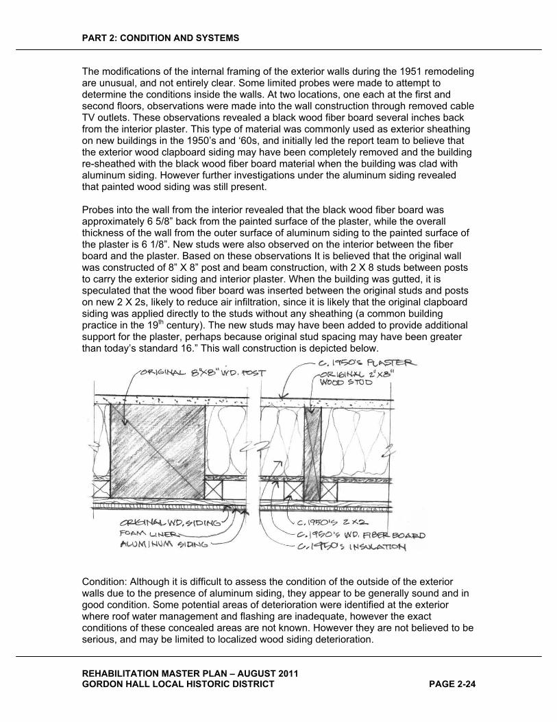
PART 2: CONDITION AND SYSTEMS
REHABILITATION MASTER PLAN – AUGUST 2011 GORDON HALL LOCAL HISTORIC DISTRICT PAGE 2-24
The modifications of the internal framing of the exterior walls during the 1951 remodeling are unusual, and not entirely clear. Some limited probes were made to attempt to determine the conditions inside the walls. At two locations, one each at the first and second floors, observations were made into the wall construction through removed cable TV outlets. These observations revealed a black wood fiber board several inches back from the interior plaster. This type of material was commonly used as exterior sheathing on new buildings in the 1950’s and ‘60s, and initially led the report team to believe that the exterior wood clapboard siding may have been completely removed and the building re-sheathed with the black wood fiber board material when the building was clad with aluminum siding. However further investigations under the aluminum siding revealed that painted wood siding was still present.
Probes into the wall from the interior revealed that the black wood fiber board was approximately 6 5/8” back from the painted surface of the plaster, while the overall thickness of the wall from the outer surface of aluminum siding to the painted surface of the plaster is 6 1/8”. New studs were also observed on the interior between the fiber board and the plaster. Based on these observations It is believed that the original wall was constructed of 8” X 8” post and beam construction, with 2 X 8 studs between posts to carry the exterior siding and interior plaster. When the building was gutted, it is speculated that the wood fiber board was inserted between the original studs and posts on new 2 X 2s, likely to reduce air infiltration, since it is likely that the original clapboard siding was applied directly to the studs without any sheathing (a common building practice in the 19th century). The new studs may have been added to provide additional support for the plaster, perhaps because original stud spacing may have been greater than today’s standard 16.” This wall construction is depicted below.
Condition: Although it is difficult to assess the condition of the outside of the exterior walls due to the presence of aluminum siding, they appear to be generally sound and in good condition. Some potential areas of deterioration were identified at the exterior where roof water management and flashing are inadequate, however the exact conditions of these concealed areas are not known. However they are not believed to be serious, and may be limited to localized wood siding deterioration.
PART 2: CONDITION AND SYSTEMS
REHABILITATION MASTER PLAN – AUGUST 2011 GORDON HALL LOCAL HISTORIC DISTRICT PAGE 2-25
ROOFS�Existing asphalt shingles appear to be in fair condition, estimated to be approximately ten years old. Flashings where raked roof edges meet vertical walls are not visible but are suspect, showing evidence of past repairs, including application of sealants and ad-hoc channels, some of which no longer exist. Interior plaster and paint deterioration correlates with some of these locations suggesting that active leakage is occurring. Similarly, north and south porch ceilings show strong evidence of leakage at such locations. It is possible that because flashing is buried behind Aluminum siding, rendering it difficult to replace, that it was not replace during past reproofing, and instead was treated with sealants and deflectors. Such treatments cannot be considered long-term repairs in such critical and vulnerable locations. It is likely that the flashings have failed. Refer to photo elevations for specific indications.
Upper roof and south porch edges have perforated drip edges to provide attic ventilation, and raised “hat” roof ventilators higher up on the roof to provide natural convective ventilation. While this system is theoretically effective, the visible hat ventilators detract from the historic character of the roof. This is more of an issue at the south porch, where the ventilator is readily visible. At the upper roof, due to the height of the building and slope of the roof, the ventilators are not readily viewed.
In some areas drip edges are missing or not properly installed potentially resulting in leakage that can contribute to deterioration.
WATER�MANAGEMENT�The building appears to have had a complete gutter and downspout system sometime in the recent past. The few gutters that remain lack downspouts. The absence of gutters in some areas appears to be contributing to leakage and deterioration observed on the interior. It also deposits water close to the building foundation, which could contribute to damp basement conditions. The 1934 HABS photographs show downspouts on the building, however it is not known if they were originally present on the house. Concerns about water management and related deterioration must be weighed against historic preservation concerns.
It should be noted that at some locations it appears that the lack of gutters may be resulting in water being directed behind aluminum siding, which may be causing concealed deterioration at some locations. Refer to photo elevations for specific indications.
FOUNDATIONS�Exposed exterior portions of foundations are in generally fair condition with localized areas where repointing is required. Refer to the photo elevations for specific indications. Also refer to the Structural Systems Analysis for additional foundation systems assessment.
OUTBUILDINGS�The Store House is in generally fair condition, with the only notable area of concern being open cracks and brick shifting under windows. This is likely due to long term water penetration around sills.

PART 2: CONDITION AND SYSTEMS
REHABILITATION MASTER PLAN – AUGUST 2011 GORDON HALL LOCAL HISTORIC DISTRICT PAGE 2-26
The garage is dates from the 1950s, and is in generally good condition, although some deterioration was noted at the juncture between the garage roof and Store House roof, appearing to be related to leakage at the valley where the two roofs meet.
INTERIOR�
GENERAL�The interior of Gordon Hall’s first and second floors generally dates from 1951 and later. At that time the building was totally gutted and interior walls were removed, with the exception of the studs for the original center hall walls, which were partially left in place. In addition, all interior finishes, trim, and doors were removed and discarded, although some doors remain in storage in the attic. Windows appear to have been retained, and some new windows were added to suit the new apartment plans.
The interior of the building has been much modified over its life, to the point that very little historic fabric remains, and the original interior spatial configuration has been completely obliterated, save for the three-bay structural arrangement.
In the former first and second floor center hall of the house, extensive changes were made to these formerly large, open spaces that extended from the front to the back of the house. The original stairs to the second floor and basement were removed, and two new stairways were cut through the first and second floors. Kitchens were constructed so that they extended into the center hall, necessitating partial removal of the central hall walls, necessitating structural modifications.
The kitchens appear to have received new appliances, cabinets and countertops at some point after they were originally built in 1951. The work is estimated to be circa 1970s.
General Assessment of Condition: The interior of the building is in generally good condition. The building appears to have been adequately maintained by the University of Michigan during their period of ownership. The state of repair is uniform throughout the house, with needed repairs consisting only of localized areas of peeling paint. Specific exceptions to this general assessment are indicated later in this section where specific architectural structural, mechanical and electrical systems are addressed.
BASEMENT�WALLS�Basement walls are in generally fair condition, with scattered repointing required throughout.
BASEMENT�CEILINGS�The current material almost totally obstructs observation of structural floor framing, and impedes its evaluation. It is not in character with the historic image of the building.
Condition: Poor.
PART 2: CONDITION AND SYSTEMS
REHABILITATION MASTER PLAN – AUGUST 2011 GORDON HALL LOCAL HISTORIC DISTRICT PAGE 2-27
BASEMENT�FLOORS�All basement floors are of recent origin, and are speculated to date from the 1951 remodeling. They are generally in good condition. The floor in the northwest wing basement is two steps below the remainder of the basement floor. The floor of the southwest wing is several inches higher than the main house, and there is a short shallow ramp into it.
Condition: Good.
INTERIOR�WALLS�–�FIRST�AND�SECOND�FLOORS�Note: for exterior walls, this section addresses only interior finishes (plaster, paint, trim, windows, and doors). For other aspects of exterior walls (such as internal wall configuration and exterior wall conditions), refer to the Exterior section above.
Since interior conditions are generally uniform throughout the first and second floors, this sections organizes information by system (e. g. “Walls,” “Ceilings,” etc.) rather than room-by-room. Where necessary, specific conditions are indicated on floor plans.
All interior walls, with the exception of portions of the former central hall walls date from the 1951 remodeling. They are constructed of 2 X 4 wood studs, with varying interior finishes: some walls are finished with plaster on metal lath, and others have plaster on gypsum board lath. All are painted. New wood trim has a simple molded profile, and is painted.
Condition: The interior surfaces of the exterior walls are in very good condition, with limited localized areas of peeling paint.
CEILINGS�Ceiling finishes all date from the 1951 remodeling. Like walls, ceiling finishes vary, some being finished with plaster on metal lath, and others have plaster on gypsum board lath. All are painted. Ceiling finishes are believed to be applied directly to the existing original joists above them. According to the HABS drawings, first floor ceilings were originally framed with a decorative plaster cornice. The current ceilings have a simplified undetailed rectangular cornice in the same location.
Condition: Ceilings are in very good condition, with limited localized areas of peeling paint.
FLOORS�The presence of finished plaster ceiling surfaces, and layers of finish flooring which at this time cannot be removed makes it difficult to assess the what remains of the original floors and floor framing. However because of the extensive work done during the remodeling – particularly in the center hall, where the original stair was infilled, and two new stairs were cut through the central hall, and at the northwest and southwest corners of the second floors, where new steps were added to access the wings, it is speculated that floor finish materials and framing components have been significantly modified to permit the addition of double headers and joists that certainly would have been installed around new floor openings in 1951. It is also likely that when these modifications were

PART 2: CONDITION AND SYSTEMS
REHABILITATION MASTER PLAN – AUGUST 2011 GORDON HALL LOCAL HISTORIC DISTRICT PAGE 2-28
made, that the resulting infills and patches were made with rough materials, with the knowledge that another finish flooring material would be installed.
Floor finishes are currently carpet in all first and second floor spaces, except in bathrooms, where floors are ceramic tile, and kitchens, where the floors are finished with sheet vinyl. The team for this report pulled up corners of carpet in several rooms, and found that in apartments, a brown wood-grained linoleum exists under the carpet. In the stairway areas, a very hard vinyl composition tile exists under the carpet. In one area, some of the linoleum was removed in an attempt to determine the nature of underlying flooring. The linoleum is adhered to the substrate with a sticky asphaltic adhesive which is difficult to remove. Under the linoleum and adhesive was a layer of plywood, approximately ¼” thick. Thus it was not possible to observe whether any original flooring survives without extensive floor finish removal. The type of wood grained linoleum observed has been seen in buildings dating back to the late 1920s. However the fact that it is installed on plywood suggests a much later origin, as plywood is a more contemporary underlayment, and thus it is speculated that the linoleum dates from the 1951 remodeling.
It is possible that some original flooring remains in some areas of the house, perhaps in large areas. At this time it cannot be determined how extensive the area is and it is likely that it is not fully intact. Thus any desire to expose original flooring as part of a restoration will necessitate patching with new boards in an attempt to match the historic materials.
Condition:Although contemporary, all carpeting, sheet vinyl, and ceramic tile flooring appears to be in good condition. The condition of substrates and extent of remaining original flooring cannot be assessed at this time. It is likely that there are extensive non-historic floor infills resulting from the 1951 remodeling.
HISTORIC�INTEGRITY�
EXTERIOR�The historic integrity of the exterior of Gordon Hall is fair. Currently the entire building is sheathed with aluminum siding and all original trim is concealed from view. The siding application was more careful and sensitive than many siding installations in that it did not result in the removal of moldings and small details, instead simply covering over them with formed aluminum sheeting. In fact it appears that most of the original wood detailing is still present. This presents a simplified and sanitized image that does not reflect the fine detail of Gordon Hall’s original image. The condition of the wood trim and siding is not known, and it is expected that some repair or replacement of concealed materials will be necessary. It appears that enough integrity remains to facilitate an accurate restoration of the exterior of the Building.
�
INTERIOR�
BASEMENT�
PART 2: CONDITION AND SYSTEMS
REHABILITATION MASTER PLAN – AUGUST 2011 GORDON HALL LOCAL HISTORIC DISTRICT PAGE 2-29
The historic integrity of the basement of Gordon Hall is good. It has been modified somewhat over its history, with some original crawl space areas having been excavated and underpinned with concrete at some point to create additional basement space, with openings added to connect the spaces. Some former brick columns have been replaced with steel columns in the large north basement space. The basement under the northwest wing is modern, being constructed of reinforced concrete, and dating from the 1951 renovation. At the same time basement stair configurations were changed. However, as a whole, the basement retains nearly all of its material integrity from its original construction. With regard to historic spatial and architectural character, the modifications that have been made over time do not significantly detract from its image as a 19th century stone masonry basement.
FLOORS�ONE�AND�TWO�
Virtually no historic integrity survives today at the first and second floors. Today these areas present the architectural character and materials of 1960s-era apartments. Although the apartment conversion was conscientiously designed and organized into quality apartments, and used some decorative moldings and trim to give it a traditional air, it presents no character that suggests the building’s historic configuration that existed prior to 1951.
The first and second floors retain almost none of their material or spatial historic integrity. In 1951, the building was completely gutted to bare studs to create apartments. No interior wall materials or finishes remain, and no interior trim remains. In addition, very few of the original interior walls remain, with the exception of portions of the studs that formed the two east/west walls that defined the original central hall, and even these sacrificed approximately 25% of their fabric when the new kitchens were constructed which penetrated into the former stair hall from the north and south apartments. Finally, the remodeled spatial organization does not in any way make gestures to the historic classic central hall Greek Revival spatial organization of the house that existed until the 1951 remodeling.
ATTIC�
The historic integrity of the attic of Gordon Hall is good. The original timber roof framing is visible, clearly depicting the original construction methods that are concealed in other areas of the house. Although an early room that was known to exist based on the 1934 HABS drawings has been removed, there is clear visible evidence of its existence in surviving studs, plaster lath and silhouettes of the earlier construction on the walls. While the current stairway is not in the original location, again there is clear evidence of the original stair’s location in the infill boards on the floor.
HAZARDOUS�MATERIALS��Hazardous building materials are often present in historic structures due to the ubiquity of the offending building materials during certain eras and the longevity of the building in question. There is a high probability that at some point in the life of the Gordon Hall, some building products that contain hazardous materials, including asbestos and lead, were utilized and may still be present. HopkinsBurns Design Studio is not certified to identify and assess the risks of hazardous building materials. To that end, it is the recommendation of this report that (1) a hazardous materials specialist is hired to assess the risks and propose an abatement strategy; and (2) the proposed abatement is carried
PART 2: CONDITION AND SYSTEMS
REHABILITATION MASTER PLAN – AUGUST 2011 GORDON HALL LOCAL HISTORIC DISTRICT PAGE 2-30
out by contractors who are specifically licensed to perform hazardous material abatement.
LEAD�Prior to the late 1970s, lead pigment was a major component in oil-based paints because it contributed to superior hiding power, weathering, resistance to wear and decreased drying times. Lead poisoning is a disease initiated by eating, drinking or inhaling lead and can cause severe health issues and, in extreme cases, death. During the building renovation process, when building materials containing lead may be demolished, scraped, stripped or sawn, there is a high danger of ingesting airborne lead particles. Lead-based paints were banned in 1978. For more information, visit www.epa.gov/lead/.
ASBESTOS�Asbestos mineral fibers were used in many building materials beginning in the late 1800s and continuing through the first half of the twentieth century. It has been determined that, when inhaled, airborne asbestos fibers can penetrate lung tissue and increase the risk of contracting several serious lung diseases. Today, asbestos is no longer used as a constituent in building products and materials, and has been classified as a carcinogen by regulatory agencies. For more information, visit www.epa.gov/asbestos/.
CAPACITY�FOR�EXPANSION�The site offers some capacity for new structures to accommodate expanded activities, without diminishing the historic setting of Gordon Hall. New space can be gained from reconstruction of lost historic structures. HABS drawings and photographs, other historic photographs, and the Emil Lorch studies provide enough detail to permit reconstruction of the north wing to its exterior appearance during the period of significance. This structure could contain a large interior space that could accommodate large gatherings, while providing amenities such as storage and toilet facilities.
Additional interior space could be gained through reconstruction of outbuildings such as barns, which could provide considerable interior space.
STRUCTURAL�SYSTEMS�ANALYSIS�The following structural analysis was submitted by Stephen M. Rudner, P. E. Structural Engineer with Robert Darvas Associates.
DESCRIPTION�OF�FRAMING�In the basement, a small fraction of the first floor framing can be seen through some small openings in the ceiling finish however the second floor framing is completely obscured by the finish materials so no observations of the structural system was possible other than to estimate the depth of the framing by taking vertical measurements in the stairwell area. The observed first floor framing sizes are noted on the attached drawing.

PART 2: CONDITION AND SYSTEMS
REHABILITATION MASTER PLAN – AUGUST 2011 GORDON HALL LOCAL HISTORIC DISTRICT PAGE 2-31
In the central part of the building there are three structural bays. The 11.5-foot wide central stair hall bay is flanked on each side by bays that are approximately 18.5 foot wide. First floor joists in these bays are timber joists 2.75” x 9.5” spaced at 13.5” c/c. In the south bay, the first floor joists appear to clear span however in the north bay the joists are supported on a central 8” x 8” timber beam. This timber beam is dropped below the framing and is supported on one brick column and two steel pipe columns. There is also an 8” x 8” timber beam below the north corridor wall supported on three brick columns. The west span of this beam has been cut out for the non-original west stair. This beam is set up into the floor with the joists bearing in mortise slots in the beam. The load on this beam line is considerable. This beam supports the first floor, second floor and attic level floor loads; as well as the roof load; and the weight of the first and second level corridor wall.
It was observed at several locations that notches had been cut into the floor joists for installation of piping and wiring. These notches reduce the joists’ capacity below the calculated capacity for a joist of full cross section.
The southwest corner room has 7.25” to 8.5” deep x 2” wide joists at 13.5” to 14.5” spacing spanning to a central 8” x 8” timber beam supported on one brick column and one pipe column. The beam is set up into the floor framing such that the joists bear in mortise slots in both sides of the beam. At one location where the ceiling finish is not present near some plumbing, it was observed that the joists are deeply notched for the plumbing, reducing their capacity.
The northwest corner room is framed with newer 2x10’s at 16” c/c dating from the 1950’s. These joists clear span approximately 18 feet. The current thought is that they are at the wrong elevation for the intended future use and will need to be lowered or replaced.
RESULTS�OF�CALCULATIONS�The calculations done to date are for the first floor framing only as no second floor framing could be observed. It has been assumed that the building floor plan will be returned to the historic floor plan with the single central stair replaced in the central hall and the two non-original stairs at the east and west ends of the central hall removed. This restoration will necessitate re-framing the non-original stair areas as the historic framing was cut and removed to create the openings.
The wing to the north-west is to be re-built in a configuration that will provide a large meeting room with support spaces and toilet rooms etc. The southwest wing will be public space on the first floor and office use on the second floor.
The calculations performed are for the lumber sizes observed at the few areas where observations were possible. The calculations assume the lumber is in good condition and has not been damaged by deterioration and/or notching and drilling by tradesmen. However, it was observed that there is damage in some locations due to notching and drilling which will need to be addressed once all of the framing can be observed. Allowable stresses for the lumber have been assumed based upon the observed condition of the framing as follows:
1. Allowable extreme fiber bending stress 1750 psi for repetitive members 2. Allowable horizontal shear stress 120 psi
PART 2: CONDITION AND SYSTEMS
REHABILITATION MASTER PLAN – AUGUST 2011 GORDON HALL LOCAL HISTORIC DISTRICT PAGE 2-32
3. Modulus of elasticity 1,750,000 psi
Floor loads have been assumed to be 100 psf live load and 15 psf dead load on the first floor due to the assembly use and the belief that the plaster ceiling will be removed from the underside of the first floor joists.
The calculations indicate that the 2.75” x 9.5” first floor joists at 13.5” c/c in the central hall and the two flanking bays would have adequate bending capacity for assembly use however any end notching for mortise and tenon type joinery which exceeds 1.75” depth for joists in the south bay with the 18 foot clear span would decrease the calculated capacity below the desired 115 psf total load capacity. The joists in this bay that were able to be observed had notching that would also reduce their capacity. As a result, this bay will likely need to be strengthened with a central beam similar to the north bay.
The 8”x8” timber beam that supports the mid-span of the joists in the north bay of the main house calculates to be of adequate capacity for assembly use.
The 8”x8” timber beam that lies below the north corridor wall is extremely overstressed and will require reinforcement. This beam supports load from the first floor, second floor, attic floor, and roof framing as well as the weight of the corridor wall above. The west span of this beam has been cut and discarded to make room for the non-original west stair. A new beam will be required here if the non-original west stair is to be eliminated and the corridor wall at the first and second levels above re-built in their original location.
The first floor framing of the southwest corner room consists of two spans of joists spanning north-south to a central east-west beam supported on one brick column and one pipe column. The joist size and spacing was observed to vary from 7.25” x 2” to 8.5” x 2” at spacings of 13.5” to 14.5”c/c. The central beam is an 8”x8” timber set up into the floor such that the joists are supported on the north and south sides of the beam via mortise and tenon joinery. The bending stress in these joists if in un-damaged condition would be acceptable for assembly use however the deeply notched ends at the attachment to the central beam will require reinforcement as any notch deeper than 1.25” here will reduce the capacity below the required capacity. The observed notches were typically half the member depth. The central beam in this area would be acceptable as well if not for the mortise notches however its section is significantly reduced by these notches and this beam will require reinforcement to achieve an assembly area floor capacity in the space above.
The northwest wing dates from the early 1950’’s and has 2x10’s at 16”c/c spacing spanning north-south clear span. These joists are not rough sawn as the other floor joists in the older parts of the building but are surfaced on four sides. They do not have adequate capacity for assembly use and would require a beam to be introduced near mid-span to permit such capacity. I am told by the Architect they are at the wrong elevation to serve as the floor of the meeting room and that they will need to be removed and re-installed at a lower elevation.
The porch floors on the north, south, and east sides appear to have 2x6 framing at 18” to 24”c/c spacing spanning between 8” wide x 9.5” deep reinforced concrete beams. The capacity of the beams cannot be calculated without knowing the size, strength, and arrangement of the reinforcing bars as well as the strength of the concrete. The 2x6

PART 2: CONDITION AND SYSTEMS
REHABILITATION MASTER PLAN – AUGUST 2011 GORDON HALL LOCAL HISTORIC DISTRICT PAGE 2-33
porch floor joists span approximately 9 feet and are significantly overstressed in bending when 100 psf live load is applied.
No analysis was performed on the second floor or attic floor framing as it was not visible at all during my inspection. No analysis of the roof framing was performed as the roof framing appeared to be intact and mainly in need of some additional anchors to tie the rafters to the beams and the beams to the knees and columns.

PART 2: CONDITION AND SYSTEMS
REHABILITATION MASTER PLAN – AUGUST 2011 GORDON HALL LOCAL HISTORIC DISTRICT PAGE 2-34
MECHANICAL�SYSTEMS�ANALYSIS�
EXISTING�HVAC�SYSTEMS�–�CONDITION��
BOILER�
Abandoned in place, last serviced on 09-05-80. Based on the tag it is safe to conclude that the boiler hasn’t been in operation since approximately 1982. Boiler and all related equipment appears to be in very poor condition
HEATING�HOT�WATER�DISTRIBUTION�SYSTEM�
Abandoned in place; likely served finned tube radiation & convectors with manual control valves on each floor of the building that were removed when the boiler was deactivated. Copper heating hot water supply and return piping in the building appears to be in fair condition, however because of the age of the piping it is suspected that the piping has a build-up of scale within.
EXISTING�FUEL�OIL�FILL�PIPING�
Still be in place extended and abandoned at the outside wall.
ELECTRIC�RADIANT�HEATING�PANELS�
It is assumed the heaters and all other electrical accessories and controls were installed when the boilers were de-activated. The electric heaters appear to be functioning and in fair condition, however due to their age, location and size it is doubtful they are providing the required heat output to overcome the heat loss in the existing structure.
KITCHEN�VENTILATION�
Existing Kitchen ventilation will not be appropriate for the proposed use.
MECHANICAL�MAKE�UP�AIR�
Not provided for any areas of the building
TOILET�ROOM�EXHAUST�FANS�
None currently exist.
EXISTING�PLUMBING�SYSTEMS�–�CONDITION��LOCHINVAR�HSP�18�082”�82�GALLON,�18�KW�AT�240�VOLT�/�1�PHASE�ELECTRIC�WATER�HEATERGood condition.
WATER�DISTRIBUTION�PIPING�
The piping appears to be in fair condition, however because of the age of the galvanized piping, it is suspected that the piping is corroded on the inside with a build-up of scale within.
PIPING�INSULATION�
Suspicious pipe insulation in fair condition was observed where piping is exposed.
PART 2: CONDITION AND SYSTEMS
REHABILITATION MASTER PLAN – AUGUST 2011 GORDON HALL LOCAL HISTORIC DISTRICT PAGE 2-35
SANITARY�WASTE�AND�VENT�PIPING�
The condition of the sanitary drainage piping is suspect because of its age.
KITCHENS�
Appear to be fully functional and are in fair / poor condition with dated plumbing fixtures.
KITCHEN�PIPING�
Concerns listed in the first paragraph also apply for all concealed piping mains.
BATHROOMS�
All the lavatories, tank type water closets, bathtubs and related trim appear to be dated. Fixtures and trim in fair / poor condition. The existing fixture installation does not comply with current A.D.A. standards in any parts of the building.
BATHROOM�PIPING�
Piping concerns listed in the first paragraph also apply for all concealed piping mains.
PART 2: CONDITION AND SYSTEMS
REHABILITATION MASTER PLAN – AUGUST 2011 GORDON HALL LOCAL HISTORIC DISTRICT PAGE 2-36
ELECTRICAL�SYSTEMS�ANALYSIS�
ELECTRIC�SERVICE�AND�POWER�DISTRIBUTION�The existing underground 240 / 120 volt, single phase, three wire DTE Energy electric service conductors and associated conduit from the pad mounted transformer to the surface metal “wireway” appears to be in good condition; however the capacity of this service is not adequate to support the proposed new use.
The existing surface metal “wireways” located at the exterior backboard with the DTE Energy utility meters varies in condition from good to fair depending on the location of the wireway. The wireway located above the utility meters have considerable oxidation and rust, and are in fair condition. The wireways located below the utility meters do not show any obvious signs of oxidation or rust, but the finish shows some fading and deterioration from exposure to the elements. The lower wireways would be considered to be in good condition. While the condition of the lower wireways would provide an opportunity for re-use, the proposed building use and the associated electrical service requirements are such that there will not be a need for these wireways as part of the rehabilitation.
The single 3-1/2” steel conduit from the lower wireway, below the utility meters, with the AWG #2 and #2/0 conductors appears to be in good condition; however the multiple AWG #2 and #2/0 conductors that enter the structure at the Basement Laundry room are not adequately sized for the proposed new use. While the condition of the single 3-1/2” steel conduit provides an opportunity for re-use, the configuration and location of the raceway makes re-use unlikely for the proposed new use.
The four (4) DTE Energy utility meters serving the existing apartment units in the house, and the fifth DTE Energy utility meter serving the “house” loads are in good condition; however these meters are not adequate for the proposed new use. It is possible for one (1) of the meter enclosures to be re-used for the new utility metering to the structure; however the final determination will need to be made by DTE Energy based on the new electric service configuration.
The four (4) 100A-2P circuit breaker type main disconnect switches for the apartment units and the one (1) 150A-2P circuit breaker type main disconnect switch for the “house” loads are in fair condition. Due to the switches being located in the Basement Laundry Room, which was has high moisture content due to the open laundry tubs, as well as a sump pump in this room, there is considerable oxidation and rust on the wireway below the main switches, and on the main switch enclosures. Given the size and configuration of these existing circuit breaker main switches, as well as their current condition, it is unlikely that these switches can be re-used for the proposed new use.
The electric service “electrode grounding” for the service occurs at the 150A-2P main circuit breaker serving the “house” loads only; the location of the grounding electrode (aka “ground rod”) and the point of termination of the copper electrode grounding conductor from the main circuit breaker was not able to be visually indentified during the survey of the building and site. A visual inspection indicates that the existing electrode grounding connection at the main switch appears to be in good condition; however the
PART 2: CONDITION AND SYSTEMS
REHABILITATION MASTER PLAN – AUGUST 2011 GORDON HALL LOCAL HISTORIC DISTRICT PAGE 2-37
configuration and size of this electrode grounding conductor is not adequate for the proposed new use.
Each of the four (4) apartment units have a 100 ampere main lugs only, 240 /120 volt single phase three wire circuit breaker type lighting panel located in a closet just off the unit Kitchen. The currently installed locations of the lighting panels in the closet is a violation of the current National Electrical Code (N.E.C.) since there is not adequate working clearance provided in front of the panels, with most of the closets having shelving in front of the panels that prevent access to the panels as required by the N.E.C. In general the condition of these panels is good but unlikely to be adequate for the proposed new use.
The existing house lighting panel “LP-HA” located at the Basement across from the boiler appears to be in good condition, but is unlikely to be adequate for the proposed new use.
The existing screw-base fuse type house lighting panel, located next to panel “LP-HA” at the Basement, is in fair condition. There appears to be a couple of branch circuits served out of this panel that have fuses installed for the conductor protection that are larger than allowed by the N.E.C. for the size of conductors. For example, there are a couple of cases where 25 ampere or 30 ampere fuses are installed, but the wiring from the fuse appears to be AWG #12, which per the N.E.C. Table 310-16 are rated for a maximum fuse size of 20 amperes. There are also a couple of cases in this panel where more than one (1) conductor is terminated at the fuse terminal screw. This is a violation of the N.E.C. which allows only a single conductor to be terminated at the fuse terminal screw. It is unlikely that this panel will be utilized for the proposed new use.
All of the feeders serving the noted apartment and “house” lighting panels appear to be installed in metal raceways (aka “conduit”); however none of the feeders include a separate equipment grounding conductor to the panels. It appears that the system is utilizing the raceway as the equipment grounding path. All of the conductors appear to be in good condition but unlikely to be adequate for the proposed new use.
INTERIOR�LIGHTING�The existing lighting is a mixture of incandescent and fluorescent lighting fixtures, all of which appear to date from the renovation work that occurred in 1950 to create the multi-family residences and the associated maintenance of the facility over the fifty (50) years of operation as a multi-family residence. The fluorescent lighting appears to be limited to the Basement Laundry room and the Kitchens in the four (4) apartment units. The lighting is in good to fair condition but unlikely to be re-used for the proposed new use.
The existing apartment unit on the first floor, north side, has recently upgraded the lighting to a decorative type of incandescent lighting that is unique among the four (4) existing apartment units, and was performed after the building was acquired by the Dexter Area Historical Society. The lighting in this unit consists of residential grade decorative surface and pendant mounted incandescent fixtures that were purchased from a local home improvement store and installed by the Historical Society. The lighting appears to be in good to excellent condition but unlikely to be re-used for the proposed new use.
PART 2: CONDITION AND SYSTEMS
REHABILITATION MASTER PLAN – AUGUST 2011 GORDON HALL LOCAL HISTORIC DISTRICT PAGE 2-38
In addition to the lighting noted above, ceiling fans with light kits are installed in all of the apartment units with the exception of the first floor, north side unit. The ceiling fans appear to date from a period after the original conversion of the building to a multi-family residence; however the exact period of the ceiling fan installation was not able to be determined. The ceiling fans and light kits appear to be in fair condition but are unlikely to be re-used for the proposed new use.
Since the proposed period of significance is circa 1826 to 1865, all of the existing lighting and ceiling fans described above did not exist and are anachronistic to this time period.
EMERGENCY�AND�EXIT�LIGHTING�Emergency and exit lighting does not currently exist in the facility.
EXTERIOR�LIGHTING�Outdoor lighting is mostly building mounted with either recess mounted or surface mounted incandescent lighting fixtures located at the ceiling of each of the porches. The fixtures are in fair to poor condition and unlikely to be re-used for the proposed new use.
In addition to the ceiling mounted lighting fixtures noted, there is a single decorative wall mounted “carriage-type” light fixtures with an American eagle motif located high above the door, just below the second floor window, over the entry door at the east porch. This fixture is in fair condition, but unlikely to be re-used for the proposed new use.
A surface wall mounted incandescent globe and guard type light fixture (aka “jelly jar”) is located at the exterior door to the second floor balcony. This fixture is in fair condition and unlikely to be re-used for the proposed new use.
The single pole mounted, approximately 15’-0” high HID light fixture located on the north side of the building near the parking area appears to be in fair to poor condition and unlikely to be re-used for the proposed new use.
A bare lamp holder type fixture is installed under the soffit of the garage on the south side of the garage, and provides exterior lighting along the south side of the garage. This fixture is in fair condition and unlikely to be re-used for the proposed new use.
Since the proposed period of significance is circa 1826 to 1865, all of the existing exterior building mounted lighting described above did not exist and is anachronistic to this time period.
BRANCH�WIRING�AND�DEVICES�The majority of the branch circuit wiring serving the “house” loads and at least one of the apartment units appears to be separate conductors installed in a metal raceway (aka “conduit”). The wiring all appears to be copper, with modern insulation material on the vast majority of the installed wiring. Only a few existing “house” branch circuits fed from the existing screw-base fuse lighting panel in the Basement utilize cloth covered wiring. The branch circuit wiring that utilizes thermoplastic insulation appears to be in good condition. The branch circuit wiring that utilizes the cloth covering appears to be in fair condition and unlikely to be adequate for the proposed new use.
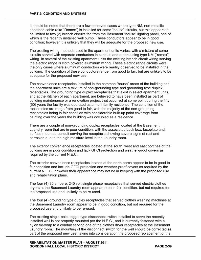
PART 2: CONDITION AND SYSTEMS
REHABILITATION MASTER PLAN – AUGUST 2011 GORDON HALL LOCAL HISTORIC DISTRICT PAGE 2-39
It should be noted that there are a few observed cases where type NM, non-metallic sheathed cable (aka “Romex”) is installed for some “house” circuits, but this appears to be limited to two (2) branch circuits fed from the Basement “house” lighting panel, one of which is the recently installed well pump. These conductors appear to be in good condition; however it is unlikely that they will be adequate for the proposed new use.
The existing wiring methods used in the apartment units varies, with a mixture of some circuits served with separate conductors in conduit, and others using type NM (“romex”) wiring. In several of the existing apartment units the existing branch circuit wiring serving the electric range is cloth covered aluminum wiring. These electric range circuits were the only cases where aluminum conductors were readily observed to be installed in the building. The condition of these conductors range from good to fair, but are unlikely to be adequate for the proposed new use.
The convenience receptacles installed in the common “house” areas of the building and the apartment units are a mixture of non-grounding type and grounding type duplex receptacles. The grounding type duplex receptacles that exist in select apartment units, and at the Kitchen of each apartment, are believed to have been installed as part of building maintenance or a renovation project that occurred at some point during the fifty (50) years the facility was operated as a multi-family residence. The condition of the receptacles are range from good to fair, with the majority of the non-grounding receptacles being in fair condition with considerable built-up paint coverage from painting over the years the building was occupied as a residence.
There are a couple of non-grounding duplex receptacles located at the Basement Laundry room that are in poor condition, with the associated back box, faceplate and surface mounted conduit serving the receptacle showing severe signs of rust and corrosion due to the high moisture level in the Laundry room.
The exterior convenience receptacles located at the south, west and east porches of the building are in poor condition and lack GFCI protection and weather-proof covers as required by the current N.E.C.
The exterior convenience receptacles located at the north porch appear to be in good to fair condition and include GFCI protection and weather-proof covers as required by the current N.E.C.; however their appearance may not be in keeping with the proposed use and rehabilitation plans.
The four (4) 30 ampere, 240 volt single phase receptacles that served electric clothes dryers at the Basement Laundry room appear to be in fair condition, but not required for the proposed use and unlikely to be re-used.
The four (4) grounding type duplex receptacles that served clothes washing machines at the Basement Laundry room appear to be in good condition, but not required for the proposed use and unlikely to be re-used.
The existing single-pole, toggle type disconnect switch installed to serve the recently installed well is not properly mounted per the N.E.C., and is currently fastened with a nylon tie-wrap to a conduit serving one of the clothes dryer receptacles at the Basement Laundry room. The mounting of the disconnect switch for the well should be corrected as part of the proposed new use, taking into consideration the proposed replacement of the
PART 2: CONDITION AND SYSTEMS
REHABILITATION MASTER PLAN – AUGUST 2011 GORDON HALL LOCAL HISTORIC DISTRICT PAGE 2-40
existing water service with a larger incoming service size and well pump. Refer to the mechanical section of the report for additional information.
FIRE�ALARM�AND�SECURITY�SYSTEM�The 120 volt single station smoke alarms installed throughout the building appear to be in fair condition but unlikely to be re-used for the proposed new use.
The security system smoke detectors that are installed throughout the existing building appear to be in good condition; however the capability of the existing security system may not be adequate to support the fire alarm system requirements for the proposed new use.
The security system keypad for the control of the system, and located at the First Floor north apartment unit, in the back hallway near one of the bedrooms, appears to be in good condition.
MISCELLANEOUS�SYSTEMS�The telephone and cable television utility services to the building are located on the building exterior just south of the west porch. The services enter through the building wall at this location into the house. The system is a typical residential type system in fair condition, and may not be adequate for the proposed new use. In addition, the current entry location and equipment mounted on the building exterior detract for the appearance of the building and consideration should be given to relocating all of this equipment to the building interior at an equipment area in the renovated Basement.
The door buzzers and apartment entry system appears to be in fair condition; however there is no need for these systems as part of the proposed new use.
LIGHTNING�PROTECTION�SYSTEM�The lightning protection system appears to be in fair to poor condition, and shows signs of deterioration due to a lack of maintenance. In addition, as noted in the physical description section of this report, the chimney is lacking lightning protection system air terminals which expose the structure to a potential lightning strike due to the level of the chimney above the roof line.
The supports for the lightning protection system down conductors from the air terminals on the roof to the ground rods at the base of the building appear to be missing in many observed cases. The overall condition of the down conductors and associated ground rods appears to be fair. The entire lightning protection system is in need of maintenance and repair.

PART 2: CONDITION AND SYSTEMS
REHABILITATION MASTER PLAN – AUGUST 2011 GORDON HALL LOCAL HISTORIC DISTRICT PAGE 2-41
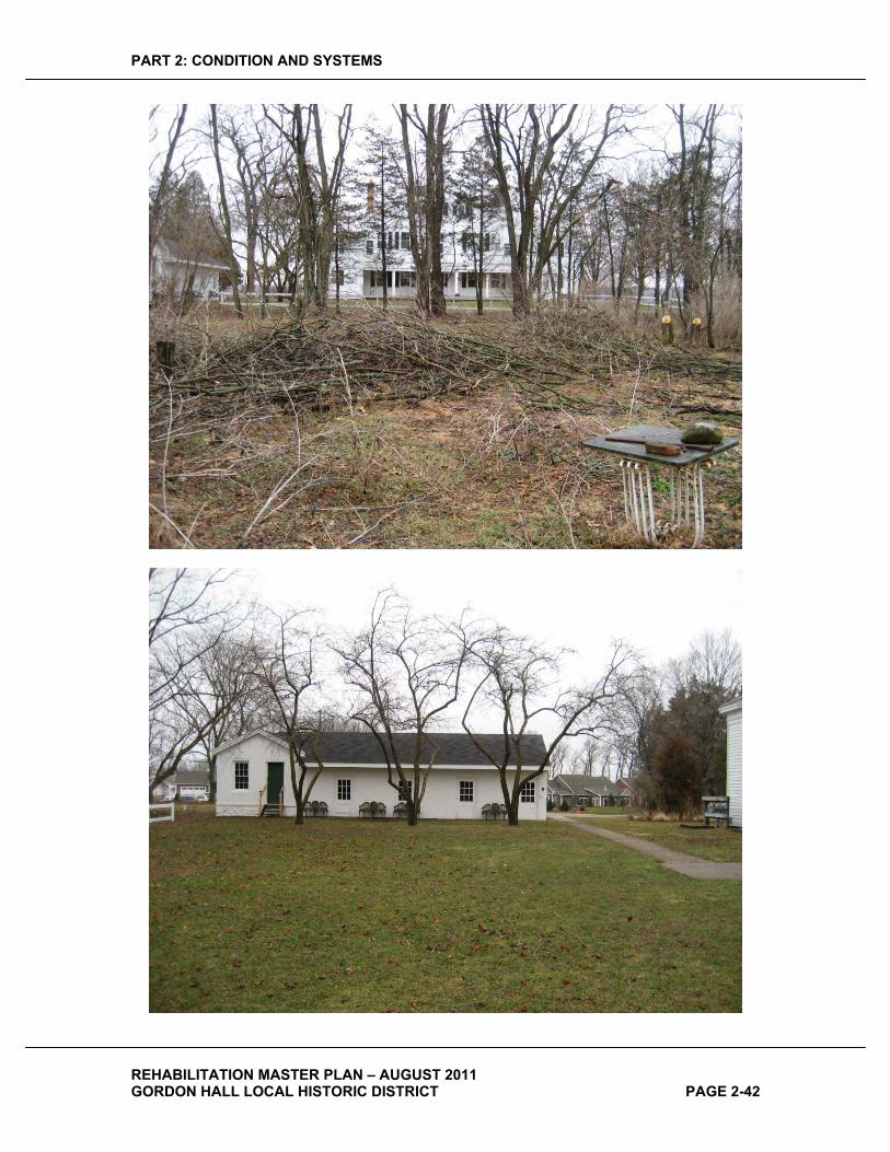
PART 2: CONDITION AND SYSTEMS
REHABILITATION MASTER PLAN – AUGUST 2011 GORDON HALL LOCAL HISTORIC DISTRICT PAGE 2-42
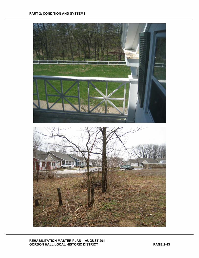
PART 2: CONDITION AND SYSTEMS
REHABILITATION MASTER PLAN – AUGUST 2011 GORDON HALL LOCAL HISTORIC DISTRICT PAGE 2-43
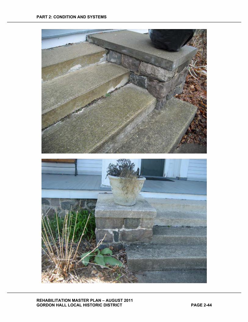
PART 2: CONDITION AND SYSTEMS
REHABILITATION MASTER PLAN – AUGUST 2011 GORDON HALL LOCAL HISTORIC DISTRICT PAGE 2-44

PART 2: CONDITION AND SYSTEMS
REHABILITATION MASTER PLAN – AUGUST 2011 GORDON HALL LOCAL HISTORIC DISTRICT PAGE 2-45

PART 2: CONDITION AND SYSTEMS
REHABILITATION MASTER PLAN – AUGUST 2011 GORDON HALL LOCAL HISTORIC DISTRICT PAGE 2-46

PART 2: CONDITION AND SYSTEMS
REHABILITATION MASTER PLAN – AUGUST 2011 GORDON HALL LOCAL HISTORIC DISTRICT PAGE 2-47
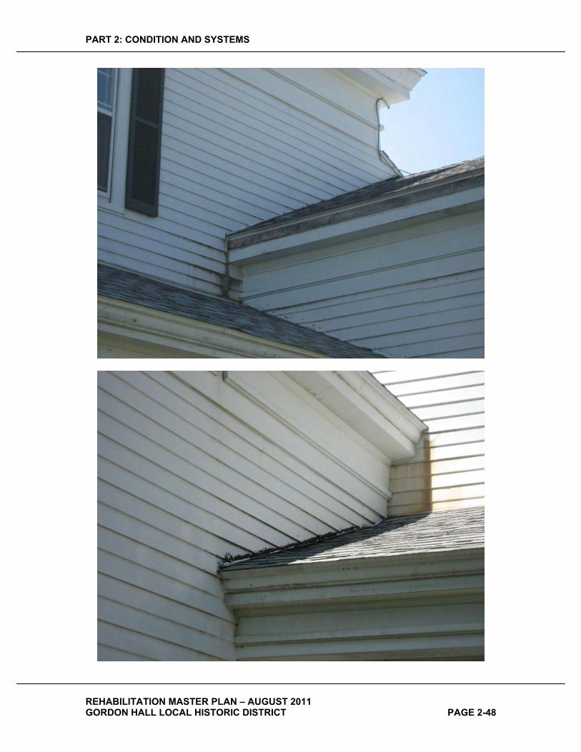
PART 2: CONDITION AND SYSTEMS
REHABILITATION MASTER PLAN – AUGUST 2011 GORDON HALL LOCAL HISTORIC DISTRICT PAGE 2-48
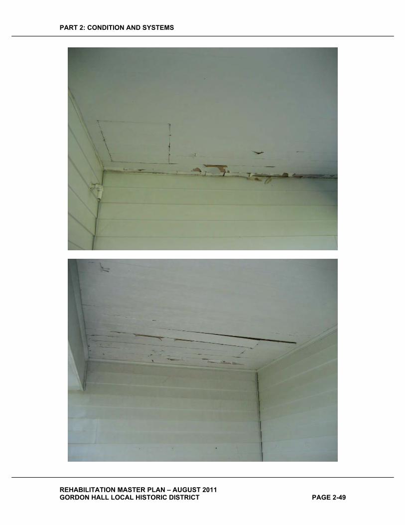
PART 2: CONDITION AND SYSTEMS
REHABILITATION MASTER PLAN – AUGUST 2011 GORDON HALL LOCAL HISTORIC DISTRICT PAGE 2-49
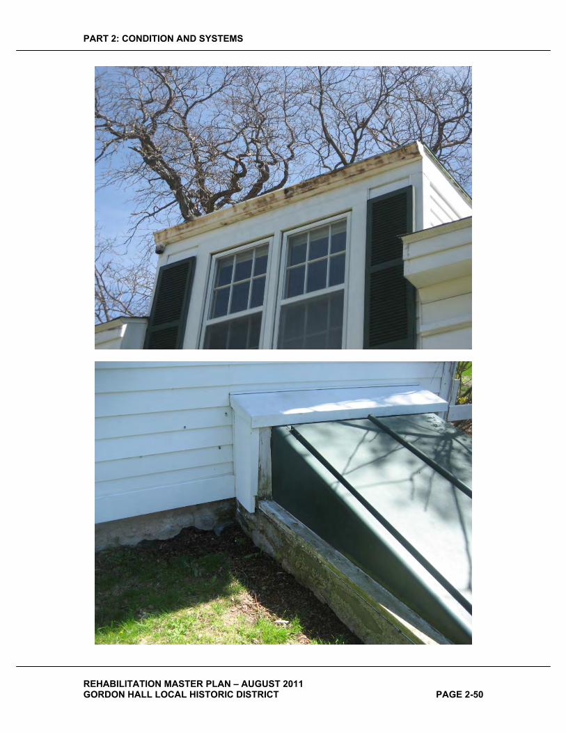
PART 2: CONDITION AND SYSTEMS
REHABILITATION MASTER PLAN – AUGUST 2011 GORDON HALL LOCAL HISTORIC DISTRICT PAGE 2-50

PART 2: CONDITION AND SYSTEMS
REHABILITATION MASTER PLAN – AUGUST 2011 GORDON HALL LOCAL HISTORIC DISTRICT PAGE 2-51
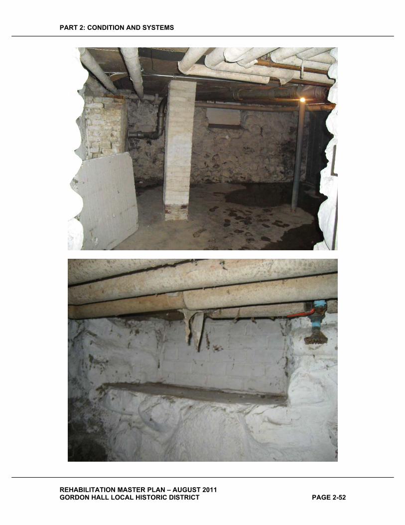
PART 2: CONDITION AND SYSTEMS
REHABILITATION MASTER PLAN – AUGUST 2011 GORDON HALL LOCAL HISTORIC DISTRICT PAGE 2-52
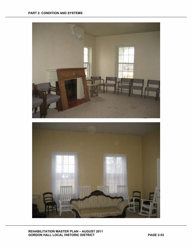
PART 2: CONDITION AND SYSTEMS
REHABILITATION MASTER PLAN – AUGUST 2011 GORDON HALL LOCAL HISTORIC DISTRICT PAGE 2-53
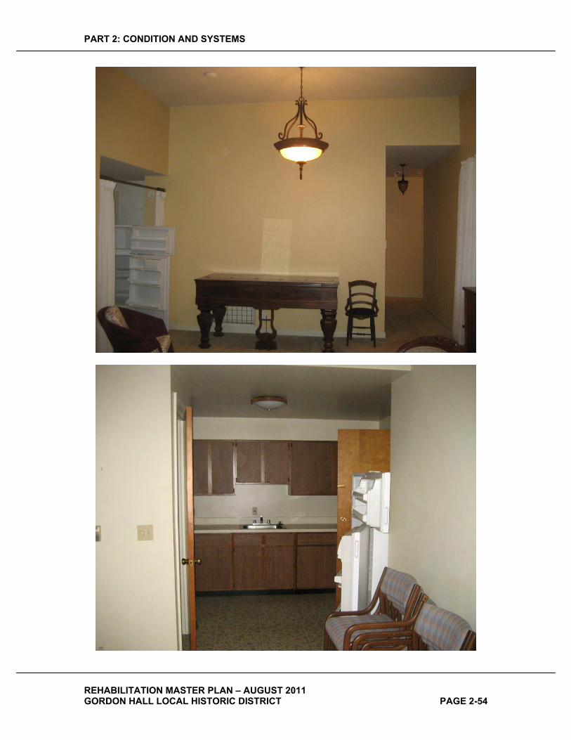
PART 2: CONDITION AND SYSTEMS
REHABILITATION MASTER PLAN – AUGUST 2011 GORDON HALL LOCAL HISTORIC DISTRICT PAGE 2-54
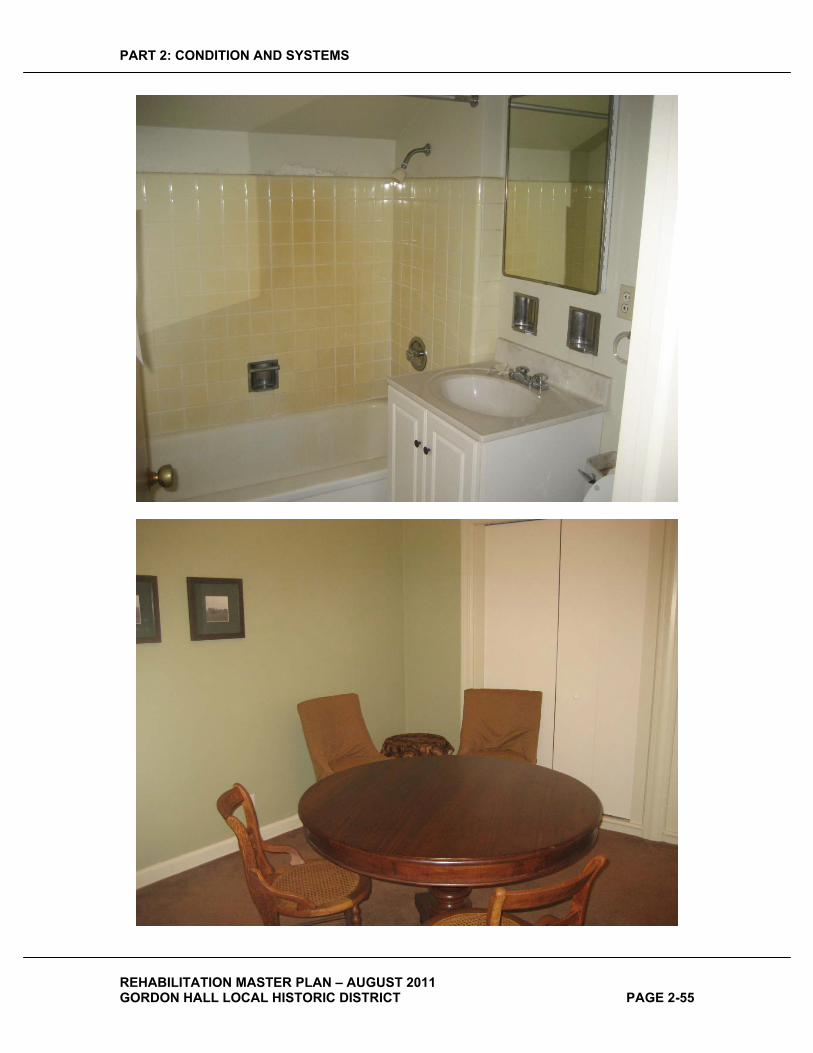
PART 2: CONDITION AND SYSTEMS
REHABILITATION MASTER PLAN – AUGUST 2011 GORDON HALL LOCAL HISTORIC DISTRICT PAGE 2-55
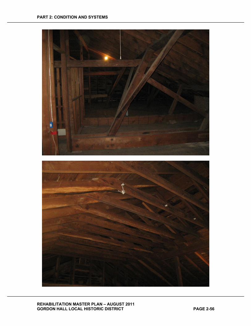
PART 2: CONDITION AND SYSTEMS
REHABILITATION MASTER PLAN – AUGUST 2011 GORDON HALL LOCAL HISTORIC DISTRICT PAGE 2-56
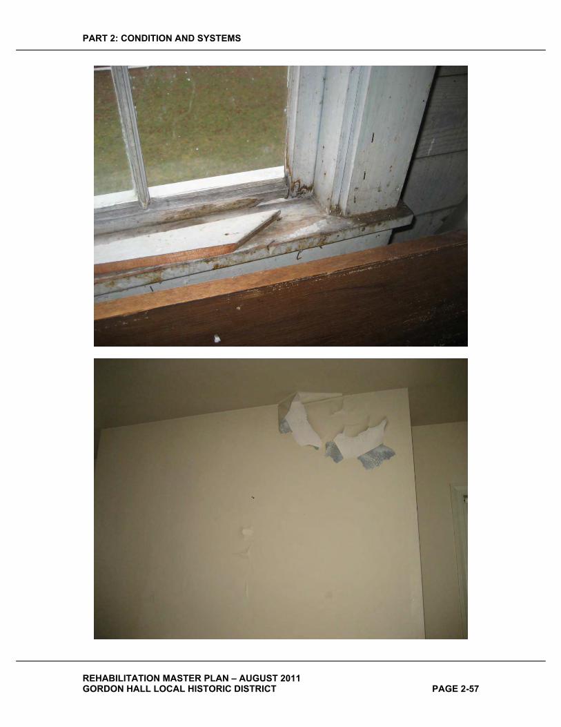
PART 2: CONDITION AND SYSTEMS
REHABILITATION MASTER PLAN – AUGUST 2011 GORDON HALL LOCAL HISTORIC DISTRICT PAGE 2-57
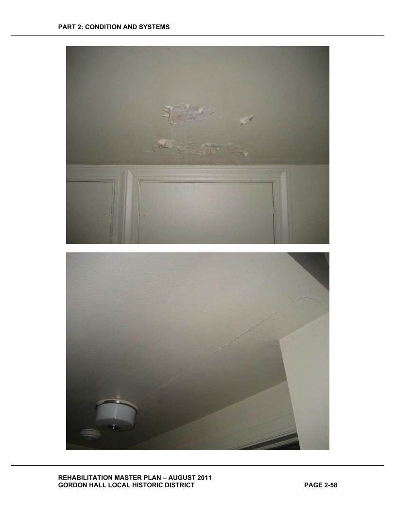
PART 2: CONDITION AND SYSTEMS
REHABILITATION MASTER PLAN – AUGUST 2011 GORDON HALL LOCAL HISTORIC DISTRICT PAGE 2-58

PART 2: CONDITION AND SYSTEMS
REHABILITATION MASTER PLAN – AUGUST 2011 GORDON HALL LOCAL HISTORIC DISTRICT PAGE 2-59

PART 3: TREATMENT AND USE
REHABILITATION MASTER PLAN – AUGUST 2011 GORDON HALL LOCAL HISTORIC DISTRICT PAGE 3-1
PART�3:�TREATMENT�AND�USE�
PLANNING�AND�ALTERNATIVES�
BUILDING�PROGRAMMING�The Dexter Area Historical Society and Museum, Washtenaw County, with the assistance of the HopkinsBurns Design Studio Team, has engaged in a programming effort for Gordon Hall. The assessment of the existing conditions and the analysis of the historic evolution of Gordon Hall have informed this programming effort. The results of this effort, discussed here, will guide future development of Gordon Hall, and is the basis for the treatments needed to support programming described elsewhere in this report.
In order to facilitate a discussion on the desired uses for Gordon Hall, a brainstorming workshop was held with Dexter Area Historical Society members and Washtenaw County representatives
The brainstorming exercise produced a list of creative ideas for the types of activities that should be hosted there. These activities ranged from museum use and meeting space to wedding receptions and woman’s suffrage historic reenactments. The list of activities has been supplemented by HopkinsBurns and grouped into seven categories; see Sheet 9 for details.
An analysis of the outcome of the programming efforts has yielded an organization of these activity categories into discrete areas within the Hall, which can be viewed on Sheets 10 and 11. It was accepted that the best use for the Basement level would be for non-public Archives, Storage and mechanical and electrical systems. The First and Second Floors shall be used primarily for public and private use such as receptions, conferences, meetings, gatherings, and similar activities, as well as provide for DAHSM’s outreach activities. The Building will provide historical displays to tell of the building’s history and of the larger context of Dexter and surrounding areas. These displays will be carefully designed and implemented so that they enable and enhance the multifunctional public and private uses listed above. It was concluded that use of the Building purely as a museum would limit public interest in it, and restrict revenue-generating activities that are necessary to provide ongoing support for Gordon Hall. We feel the museum displays that are provided should depict the period of significance of the Building. Gordon Hall itself is an exhibit so the furnishings within the Building need to portray its period of interpretation. However it is also not intended that Gordon Hall be a house museum with roped off rooms, extensive furnishings depicting a residential environment, and restricted access to spaces. Instead it is intended that the entire restored house be available for public and private functions. Furnishings would be antiques or reproductions from the period of interpretation, but should be durable and capable of continuous use by visitors. Furnishings would consist of large pieces (dining

PART 3: TREATMENT AND USE
REHABILITATION MASTER PLAN – AUGUST 2011 GORDON HALL LOCAL HISTORIC DISTRICT PAGE 3-2
tables, sofas, chairs, substantial side tables, etc.) arranged in a manner that permit all spaces in the house to be used by large groups for a variety of events.
It is understood that eventually DAHSM wishes to move the museum from its current location to the Gordon Hall site, Therefore, more general historic artifacts and displays should be housed in other buildings, both reconstructed and new, on site. Our recommended approach is to fit the appropriate activities into the original Hall that sensitively respects the original architecture. The proposed reconstruction of the northwest wing will be a contemporary space in terms of its function and, therefore, it will be very flexible from an activity standpoint. Higher impact uses should be performed in this space.
Due to the need for accessibility and the ability for the public to experience the interpretation of the entire Hall, the recommendation is for incorporating a lifting device within the original structure to accomplish these needs.
One of the unique amenities of Gordon Hall is its site. There is great opportunity for the reconstruction of original structures and the design of new context sensitive buildings for expanding programming needs, i.e. exhibit space, storage and outdoor event function needs.
PRESERVATION�ZONES�The general approach to preserving Gordon Hall has been in place since its purchase by the Dexter Area Historical Society and Museum. All of the work documented in this report has both reinforced this approach and provided the next layer of details for moving forward. The Preservation Zones, documented on Sheets 12-16 frame the understanding for what type of intervention will be necessary in each section of the Hall.
The definitions of the preservation zones are provided below by the National Park’s Service (NPS) within the Secretary of the Interior’s Standards for the Treatment of Historic Properties. The team is using these definitions to help the project team frame an understanding for the approach to the Hall. For further description of these terms, see the website for the http://www.nps.gov/hps/tps/standguide/index.htm
Preservation Preservation is defined as the act or process of applying measures necessary to sustain the existing form, integrity, and materials of an historic property. Work, including preliminary measures to protect and stabilize the property, generally focuses upon the ongoing maintenance and repair of historic materials and features rather than extensive replacement and new construction. New exterior additions are not within the scope of this treatment; however, the limited and sensitive upgrading of mechanical, electrical, and plumbing systems and other code-required work to make properties functional is appropriate within a preservation project.
Adaptive Reuse (referred to as “Rehabilitation” by NPS) Rehabilitation is defined as the act or process of making possible a compatible use for a property through repair, alterations, and
PART 3: TREATMENT AND USE
REHABILITATION MASTER PLAN – AUGUST 2011 GORDON HALL LOCAL HISTORIC DISTRICT PAGE 3-3
additions while preserving those portions or features which convey its historical, cultural, or architectural values.
Restoration Restoration is defined as the act or process of accurately depicting the form, features, and character of a property as it appeared at a particular period of time by means of the removal of features from other periods in its history and reconstruction of missing features from the restoration period. The limited and sensitive upgrading of mechanical, electrical, and plumbing systems and other code-required work to make properties functional is appropriate within a restoration project.
New Construction (referred to as “Reconstruction” by NPS) Reconstruction is defined as the act or process of depicting, by means of new construction, the form, features, and detailing of a non-surviving site, landscape, building, structure, or object for the purpose of replicating its appearance at a specific period of time and in its historic location.
ULTIMATE�TREATMENT�AND�USE��
GENERAL�The overall treatment for the building will be Restoration, which is defined by the Secretary of the Interior’s Standards for the treatment of Historic Properties as
“…the act or process of accurately depicting the form, features, and character of a property as it appeared at a particular period of time by means of the removal of features from other periods in its history and reconstruction of missing features from the restoration period.”
The period of interpretation that will be represented in the restoration will be circa 1863, the year that Judge Samuel Dexter died. Although significant changes were made after Judge Dexter’s death, it is felt that because of the building’s association with Judge Dexter, a significant local figure, the building configuration associated with him is the most significant. In addition, the pure Greek Revival architectural expression that Judge Dexter realized in the house’s original design is viewed by historians as being a sterling example of that style of architecture. Although there were changes to the building after that time, particularly those made by his widow Millicent, they were not respectful of the essential Greek Revival style of the original house. Furthermore, these modifications, which were limited to the two wings of the building have long since been lost to demolition, having been removed in the 1940s and ‘50s.
Because of the extensive changes made to the building over its history, particularly the gutting and reconfiguration of the interior, there is almost no surviving historic fabric in the interior of the building at the first and second floors, and thus a significant amount of Reconstruction of lost features, spaces and building elements will be necessary. It is
PART 3: TREATMENT AND USE
REHABILITATION MASTER PLAN – AUGUST 2011 GORDON HALL LOCAL HISTORIC DISTRICT PAGE 3-4
believed that the essential character-defining features, details, and spatial configurations of the property remained largely unchanged from 1843 until 1951 due to the general neglect of the property between Millicent Dexter’s death in 1899 and Katharine Dexter McCormick’s purchase of the property in 1939. Thus, it is believed that the 1934 drawings depict the building much as it existed at the time of Judge Dexter’s death. While the HABS show Millicent Dexter’s tower addition, and the two story ell, the research and studies conducted by Emil Lorch in the 1940s give insight to the configuration of the Building prior to her modifications. Because of the extraordinary detail contained in the 1934 HABS drawings and photographs, it is felt that the restoration and reconstruction to the period of interpretation can be accurately accomplished.
Specifically, at this time it is the DAHSM’s intention to restore the interior of the first and second floors of the building to the original configuration. Because the essential exterior character of the house is intact under the existing aluminum siding, it is intended that the aluminum siding be removed, and that the underlying wood siding and detailing which appears to still be present, be restored.
RECOMMENDED�ALTERNATIVE�
PROPOSED�SITE�It is the desire of the Dexter Area Historical Society to restore Gordon Hall to its 1860’s appearance and configuration and make it available to the public for a variety of public and private functions, as well as for DAHSM outreach efforts. Ultimately, DAHSM wishes to relocate the current museum in the Village of Dexter to the Gordon Hall property. For this reason, planning for the future use of the buildings and grounds must take into account a significantly higher level of use than Gordon Hall on its own would generate.
OUTBUILDINGS�
As described previously, the overall intent of the master plan is for the main house to be restored and made suitable for receptions, conferences, meetings, and the like with museum displays designed to enable and enhance these multifunctional activities. The intent is that it does not become a dedicated museum or house museum.
As such, a museum to replace the current museum must be located elsewhere on site. With this in mind, the plan calls for several of the earlier outbuildings to be reconstructed and that one or more new buildings constructed to replace the current museum.
The replacement museum building(s), labeled "new barn and exhibits" on the plan, will be designed to reflect the typical barn style of the era. Where photographic evidence and/or drawings exist of the previously existing outbuildings, the replacements should be reconstructed to match their original appearance. Others should be reconstructed in the style of the other buildings.
The replacement museum building(s) will include power and HVAC service suitable for a small simple museum. All other buildings will be utilitarian with minimal power and lighting.
WALKWAYS�
PART 3: TREATMENT AND USE
REHABILITATION MASTER PLAN – AUGUST 2011 GORDON HALL LOCAL HISTORIC DISTRICT PAGE 3-5
Historically, an axial walkway, a “promenade,” extended due east from Gordon Hall to Dexter Pinckney Road. Prior to the turn of the century, this promenade was likely the main walking route to and from the Village of Dexter. Lined with trees, it provided a grand entrance to the house and a beautiful foreground setting. The proposed plan suggests a reintroduction of this promenade to provide access to site uses that might take place east of the house and to provide a future walking connection to the Village. This connection is dependent upon future improvements to the existing railroad underpass.
Two additional walkway connections to the Cedars property are recommended to facilitate pedestrian access. Although a walkway connection has already been constructed from the south side of the community building to the site, it is somewhat indirect, and therefore somewhat obscure, for those who are not familiar with the site. A direct extension of the sidewalk adjacent to the parking lot on the west side of the community building is therefore recommended. West of these connections, an additional walkway extension is recommended to facilitate access to the community gardens.
The system of walks within the building complex itself (west of Gordon Hall) has been designed to be simple and direct. A small gathering space has been located at the intersection of the two main walks. This space could be used for an informational kiosk or directory, a sitting area, or any other of a myriad of possibilities.
In general, walks constructed of concrete, asphalt, or unit pavers will lend a sense of formality that would be inappropriate to the character of the house and grounds. It is therefore recommended that the majority of the walks, including the promenade, be constructed of a “soft” material such as limestone fines. Properly installed, limestone fines are universally accessible, they hold up very well over time, and are relatively easy to maintain. Other possibilities include granite chips or irregularly placed flagstones (limestone, slate, bluestone or similar) installed on a sand base with less than tight joints.
In locations where the walks will receive consistent concentrated use (parking lot edges, bus drop-off area) and where the walks are connecting to existing concrete walks (the Cedars), the walks should be concrete.
PARKING�
Parking for approximately 50 to 60 vehicles is felt to be necessary to accommodate the everyday needs of Gordon Hall once the museum is relocated to the property. Additional temporary parking for major events could be located in the open fields east of the house and/or off-site with a shuttle service provided to bring visitors to and from the property. The Cedars of Dexter retirement community has also agreed to allow the occasional use of their community center parking lot for Gordon Hall events.
10 to 12 parking spaces are conveniently located north of the main house for handicapped parking and for short term parking. A 50 vehicle lot, sized to accommodate bus turning movements, is located west of the house. The grades in this area are 5 ft. to 10 ft. lower then those around the house so a parking lot at this location will be concealed from view of those viewing the house from the east.
PART 3: TREATMENT AND USE
REHABILITATION MASTER PLAN – AUGUST 2011 GORDON HALL LOCAL HISTORIC DISTRICT PAGE 3-6
It is important that a buffer of trees is preserved along the western property line between the parking lot and the neighborhood to the west. This buffer serves two purposes: 1) to screen the views to the neighborhood from Gordon Hall and 2) to screen the views of the parking lot from the neighboring properties.
All new parking lots and drives should be hard surfaced. Asphalt or porous pavement is the recommended surfacing for all new vehicle use areas.
CEDARS�OF�DEXTER�
The community building and parking lot for the Cedars of Dexter retirement community were located close to Gordon Hall to allow shared use of these facilities at such times that events on the Gordon Hall property required additional support. Unfortunately the orientation of these facilities does not respond well to the historical axial east/west alignment of Gordon Hall and its associated outbuildings. As such, a formal row of trees, labeled “buffer plantings” on the plan, has been included on the north property line to help conceal this orientation discrepancy and to separate the contemporary nature of the improvements on the Cedars property from the more historic plantings on the Gordon Hall property. A dense planting of cedar trees is recommended for this purpose to match the historic use of cedars to line the main drive.
TENT�
A space large enough to accommodate a tent sized for approximately 150 persons is located adjacent to the parking lot, just north of one of the new barns. This tent will be used for large events such as festivals, weddings, fundraisers, parties and other outdoor functions. Power will be provided for lighting, small musical groups, microphones, etc.
COMMUNITY�GARDENS�
An area for community gardens has been provided for the use of the residents of the Cedars. Included is an information kiosk for postings related to garden use.
VEGETATION�
In addition to the observations and recommendations regarding the existing and proposed vegetation mentioned previously, a few general recommendations should be made:
1. A tree and vegetation inventory and analysis should be undertaken to determine the condition and health of all trees of value, specifically those that have survived from the earliest days of Gordon Hall. Once their condition is known, measures should be undertaken to help insure their long term survival.
2. Great care should be taken to insure that construction activities related to the rehabilitation efforts do not disturb any trees of value. Earthwork, excavations, and materials and equipment storage should be restricted from within the drip lines of all trees to be saved
3. Woody scrub growth in the immediate proximity to the main complex of buildings, particularly invasive species such as buckthorn, should be removed where out of control.
4. New plantings should be in keeping with the historical character of Gordon Hall. While newer varieties of older species may be acceptable (assuming that the newer varieties are more hardy or disease resistant), exotic plants, formal gardens, topiary and the like should be avoided.

PART 3: TREATMENT AND USE
REHABILITATION MASTER PLAN – AUGUST 2011 GORDON HALL LOCAL HISTORIC DISTRICT PAGE 3-7
5. The views from the second floor of Gordon Hall toward the Village of Dexter are slowly being restricted by overgrown vegetation just to the southeast of the building. This vegetation, other than any trees of value, should be removed.
ARCHITECTURAL�SYSTEMS�RECOMMENDATIONS�In general, the recommended architectural treatments for the Building consist of removal of general repairs and restoration at the exterior, and restoration of the interior to its circa 1863 configuration. The north 1 ½ story ell will be reconstructed with an exterior appearance to match its historic appearance, but with a modern interior providing a large multipurpose space for meetings and events, toilet rooms, storage, and a warming kitchen to accommodate catered events. This restoration work is depicted and described in more detail on Sheets 12 and 13 (interior) and Sheets 14 – 15 (exterior).
The recommendations on the sheets are presented in three priority levels:
� Priority 1: Near-Term Items: These are items which should be undertaken immediately to protect the integrity of the structure, and generally include items that keep water and weather out of the structure, address safety issues and protect threatened historic fabric.
Although the ultimate intent is to restore the interior and exterior of Gordon Hall to its circa 1863 configuration, some priority one items will include repairs to building components such as aluminum siding, and interior plaster, that will ultimately be removed during restoration work. Although this may seem to be wasted money, it is the opinion of this report that these items must be done to continue to protect the building, and allow it to continue to be utilized for its current functions. DAHSM may elect defer or eliminate some interior items if fundraising suggests that interior restoration is imminent, or if uses of the building can tolerate some unrepaired items in non-critical spaces.
In addition the Priority 2 items noted on the drawings, the following items are Priority 2 work:
o Interior plaster repairs. o Maintenance of lighting and building systems. o Maintenance of windows, including weatherstripping, and adjustment to
permit full closure and locking to address energy conservation and security issues.
� Priority 2: Mid Term Items: These are recommendations that address cosmetic issues, less critical building fabric repairs, and some restoration items that will improve the historic image of the building.
In addition the Priority 2 items noted on the drawings, the following items are Priority 2 work:
o Stone walkways (Sheet 17). o Parking (Sheet 17). o Linkages to Cedars of Dexter (Sheet 17).

PART 3: TREATMENT AND USE
REHABILITATION MASTER PLAN – AUGUST 2011 GORDON HALL LOCAL HISTORIC DISTRICT PAGE 3-8
o Possible restoration of exterior, and interior, and reconstruction of the “ell.” *
� Priority 3: Long-Items: These items address work that will provide the final enhancement of the building and site that will complete the restoration of the site.
In addition the Priority 3 items noted on the drawings, the following items are Priority 3 work:
o Reconstruction of outbuildings. o Front tree-lined stone walkway. o Possible restoration of exterior, and interior, and reconstruction of the
“ell.” *
* Prioritization of the restoration of the interior and exterior of the house, and reconstruction of the “ell” are highly dependent upon DAHSM’s fundraising activities and the urgency of gaining interior meeting space to provide revenues. In the prioritization above, this work is assigned to both Priority 2 and 3. In the cost estimate this work is a separate line item that can be added to whichever priority level the DAHSM chooses to implement it.
STRUCTURAL�SYSTEMS�RECOMMENDATIONS�The following structural recommendations were submitted by Stephen M. Rudner, P. E. Structural Engineer with Robert Darvas Associates.
RECOMMENDATIONS�
1. Remove the ceiling finishes from the basement, first floor, and second floor ceilings to expose the first floor, second floor, and attic floor structures. This will permit observation and calculation of all floor framing conditions so that proper floor capacity can be verified and reinforcement designed if required.
2. Design and specify reinforcement for the first floor beam line and notched joist ends beneath the north corridor wall.
3. Design and specify reinforcement for the first floor beam line and notched joist ends at the south west corner room.
4. Introduce a beam line with columns near mid-span of the first floor joists in the south bay of the main part of the building similar to the beam line in the north bay to reduce the joist spans as a way of addressing the structural deficiency due to numerous notches cut into the joists by tradesmen.
5. Perform a proper deep tuck point on all historic masonry chimneys and foundation walls. See attached sketch. If possible excavate around the exterior so both the interior and exterior of the foundation walls can be tuck-pointed. If the exterior is to be excavated provide parging, waterproofing and drain tiles on the exterior below grade.
6. Remove, repair, and replace the porch columns. Many appear to have been repaired before. The detail of the columns bearing directly upon the porch floorboards is not a good detail as snowmelt and rainwater can wick up the end grain of the column staves. These staves should have the end grain sealed with an epoxy consolidant and /or borate wood preservative prior to re-installation of
PART 3: TREATMENT AND USE
REHABILITATION MASTER PLAN – AUGUST 2011 GORDON HALL LOCAL HISTORIC DISTRICT PAGE 3-9
the columns. If possible a venting detail should be added to permit the interior of the columns to be vented so they can more easily dry out after becoming wet. It may also be desirable to add a structural column inside the historic column if none exists so the shell of the column becomes decorative rather than structural. This will provide for easier maintenance in the future.
7. The porch floor joists must be reinforced to provide adequate capacity for assembly use. The strength of the reinforced concrete porch floor beams cannot be calculated due to unknown material strengths and reinforcing arrangement. These beams should either be removed and replaced with galvanized steel beams of adequate strength or else, the span of the floor joists could be shortened by adding steel beams each side of the historic concrete beam so the historic beam is left in place and not discarded but is not participating in providing the structural strength any longer.
8. Provide additional anchors and ties to resist uplift at connections of rafters to beams and beams to columns and knees etc.
GENERAL�STRUCTURAL�REMARKS�
1. The above observations, comments, and recommendations are based upon visual observations and commonly accepted structural engineering practices concerning good construction procedures.
2. The noted recommendations are a brief summary of potential repair requirements, in order to return the structural integrity of the basement walls and the framing as a whole.
3. After review and consultation with The Building Committee and demolition of ceiling finish materials as noted above, our office can be available for a complete detailed inspection and creation of a detailed report with plans and details for proper replacement, strengthening, and repairs.
4. If and when DAHSM proceeds with this work, Robert Darvas Associates, P.C. is available to provide engineering design services including production of structural drawings and specifications. Based on those construction documents, a general contractor would be hired to execute the construction, and would be responsible for construction means, methods, techniques, sequences, or procedures for safety precautions and programs, all in connection with new construction, modifications, or repairs.
5. Robert Darvas Associates, P.C. can be available for review of contractor’s repair proposals, and site observations during the construction repairs.
MECHANICAL�SYSTEMS�RECOMMENDATIONS�
HVAC�SYSTEM�RECOMMENDATIONS
We recommend that the entire mechanical system be removed and replaced with a geothermal system to serve the facilities. This would involve removing the abandoned boiler and all associated hot water heating piping & valves, hot water heating pumps, finned tube radiation, convectors, venting, controls and fuel oil piping. In addition, all existing electric radiant panels shall be removed.
The geothermal system recommended is a closed loop ground source water system utilizing vertical bores in conjunction with indoor heat pump units. A vertical bore can provide approximately 175 ft per ton of cooling. The vertical bores are typically installed at 20 feet on center with a bore size of 5 to 6 inches in diameter. Bore depths typically
PART 3: TREATMENT AND USE
REHABILITATION MASTER PLAN – AUGUST 2011 GORDON HALL LOCAL HISTORIC DISTRICT PAGE 3-10
range from 150 feet to 300 feet and are dependent on the ground conditions. The pipe sizes from the facility to the vertical bores can range from 3/4" to 1-1/2” depending on the depth of the bore and the capacity of the bore. The pipes from a vertical bore system come out of the bore hole at 5 feet below grade and are then routed to the building or to a manifold system. Since the vertical bores utilize the constant earth temperature for heat transfer, the bores can be located just about anywhere (under parking lots, landscaped areas, lawns, etc.). The cost of the vertical bores is approximately $3,600 per ton.
There are many types of heat pump units that can be implemented to meet the final design of the facilities. A majority of the heat pump units will be vertical or horizontal concealed type forced air units utilizing a duct distribution system. The heat pumps will be ducted in a similar manner to a traditional forced air system. Multiple heat pump units will be installed to provide individual temperature control throughout the different occupied areas of the facility. Water-to-water heat pumps shall also be implemented to provide either hydronic heating and/or domestic hot water.
A typical ground source heat pump operates in this basic fashion: A piping loop is buried in the ground. The ground temperature remains constant and is much warmer than the outdoor air temperature in the winter and much colder than the outdoor air temperature in the summer. Water is circulated through the loops and into the building where the heat pumps remove the heat from the water and delivers it to the air to provide heating in the winter. The process is reversed in cooling mode. Heat is removed form the inside air and transferred to the water loop which rejects this heat to the ground. The ground temperature is balanced since heat is added to the ground in the summer and heat is removed from the ground in the winter.
There are several advantages of implementing a geothermal system over a more conventional HVAC system such as:
1. Increased energy efficiency. 2. Reduced energy consumption. 3. Increased comfort level for individual temperature control. 4. Reduced maintenance on equipment. 5. Produce domestic hot water through water-to-water heat pumps and storage
tanks to eliminate the need for separate gas-fired or electric water heaters. 6. Produce hydronic heating through water-to-water heat pumps in conjunction with
finned tube radiation, convectors, radiant floor heating, snow-melt systems, etc. 7. Eliminate the need for natural gas, propane or fuel oil to serve HVAC equipment. 8. Amount of outdoor equipment is reduced.
However, there are some disadvantages of implementing a geothermal system: 1. Installation cost of the mechanical system is increased. 2. The number of qualified contractors to install the system is limited. 3. Dedicated equipment is required to provide ventilation.
Consideration was given to other systems, specifically a split zoned heat pump system, which offered the advantages of making phasing of the proposed work effective due to the ease of creating zones. However it was felt that this system was not as energy efficient as a geothermal system, and not as cost effective over time. In addition, it was felt that a heat pump system would meet the need of providing summer dehumidification
PART 3: TREATMENT AND USE
REHABILITATION MASTER PLAN – AUGUST 2011 GORDON HALL LOCAL HISTORIC DISTRICT PAGE 3-11
required to protect the building from moisture issues. A geothermal system was felt to be the most economical way to protect the building and achieve user needs.
Ventilation and make-up air for the facilities shall be provided by energy recovery ventilators and/or dedicated make-up air units. Exhaust hoods shall be installed where required to serve kitchen appliances in the warming kitchen.
All toilet rooms, janitor closets, elevator equipment room, mechanical room shall be equipped with ceiling mounted or in-line exhaust fans and ducted to a small relief hood or hoods located in inconspicuous locations on the roof. Fans shall be controlled with a time-delay switch, a manual on/off switch, an occupancy sensor or a thermostat depending on the area served. All ceiling mounted exhaust fans shall be equipped with a ceiling radiation damper if required. All exhaust ductwork shall be round or rectangular galvanized steel and shall be hard-ducted from the exhaust fans to the relief vents.
The HVAC equipment shall consist of two systems – one located in the attic space and another system located in the basement. All supply, return and exhaust ductwork shall be routed in the attic and in the basement to eliminate vertical duct runs and the need for duct chases that would disrupt the historic character of the restored spaces.
The duct distribution system serving areas with plaster ceilings shall utilize rectangular supply and return ductwork with insulated flex duct connections (5 ft maximum) to square ceiling diffusers along with ceiling mounted return grilles connected to the return air ductwork (hard-ducted) for areas served by the system installed in the attic space above. Floor registers and wall-mounted return grilles shall be installed for areas which are fed from the system installed in the basement below. Fire dampers and fire/smoke dampers shall be installed where required at rated assemblies and smoke barriers. For areas with the possibility of having exposed construction, such as the multi-purpose room, the duct distribution shall utilize exposed supply and return spiral ductwork with duct mounted grilles and registers.
The first ten feet of all supply and return ductwork from the heat pumps shall be lined with ½” acoustical duct liner. All concealed supply and return ductwork shall be insulated with 1-1/2” thick insulation. Ductwork located in the attic space shall be insulated with 2” thick insulation. All exposed ductwork does not require to be insulated. All ductwork shall be galvanized sheet metal and shall be installed per SMACNA standards.
The HVAC system shall comply with current code requirements of the 2009 Michigan Mechanical Code (MMC) as well as ASHRAE Standard 62.1-2004, ASHRAE Standard 90.1-2007 and other related codes. Each heat pump unit shall deliver the minimum amount of outside air required for the areas it serves to satisfy Table 403.3 of the MMC. Make-up air shall be provided to satisfy the exhaust requirements of the building to prohibit the building from being under a negative pressure.
All mechanical equipment shall be installed to maintain proper service clearances as well as clearances between air intakes and exhaust fans, louvers, combustion air vents and plumbing vents. All equipment locations and installation requirements shall be coordinated with architectural, structural and electrical trades.
PLUMBING�SYSTEM�RECOMMENDATIONS
PART 3: TREATMENT AND USE
REHABILITATION MASTER PLAN – AUGUST 2011 GORDON HALL LOCAL HISTORIC DISTRICT PAGE 3-12
The existing water service needs to be increased from a 1” to a 2” service. This will involve the installation of new water wells, pumps and hydro-pneumatic storage tanks.
With the installation of a geothermal system as recommended above, the requirement for a dedicated gas-fired, oil-fired or electric water heater is no longer required. As a result, the existing electric water heater shall be removed. The installation of a water-to-water heat pump unit in conjunction with a domestic hot water storage tank will satisfy the domestic hot water requirements of the facility. Solar panel collectors located in a remote inconspicuous location and solar water tanks (Lochinvar TiSun system) can also be integrated to provide additional energy savings for the domestic hot water system. Compatibility with historic with the historic image of the property must be further studied.
The existing galvanized and copper piping system should be replaced. To reduce cost, a combination of Schedule 80 CPVC piping and PEX piping can be installed in lieu of copper piping for the domestic hot and cold water piping system. To ensure domestic hot water is available at all times, a hot water return line shall be installed along with a re-circulation pump, aquastat and timer kit.
The existing cast-iron sanitary waste and vent piping should also be replaced with Schedule 40 PVC piping. All interior condensate piping and rain conductors shall also be PVC piping.
Under some circumstances there are issues related to noise from PVC or PEX supply and waste piping. Because all plumbing will be in the new “ell” addition to the building, and the main part of Gordon Hall will be restored, It is felt that noise will be less of an issue. Because this piping will be in new walls, there is ample opportunity to provide insulation and acoustical isolation at new piping. As an alternative, no-hub cast iron waste piping could be installed above grade. This would be more expensive, and it is becoming increasingly difficult to find small contractors who will work with cast iron.
All domestic water piping, rain conductors and condensate piping shall be insulated with a minimum of 1” pipe insulation.
All existing plumbing fixtures (toilets, sinks, faucets, bathtubs, showers, trim and accessories) shall be removed and replaced with new fixtures. The plumbing fixtures serving the facility shall be low-consumption. The water closets shall be 1.28 gallons per flush (GPF). The water closets shall be barrier-free height, tank-type toilets with trip levers and elongated bowls. The lavatories will be equipped with 0.5 gallons per minute (GPM) manually operated faucets. Kitchen sinks shall be stainless steel equipped with a single lever, low-flow faucet. All plumbing fixtures providing hot water for hand washing (lavatories, sinks, etc.) shall be equipped with an ASSE 1070 thermostatic mixing valve to limit the hot water temperature to 110°F.
Roof drainage shall be provided through gutters and downspouts for pitched roofs. Location and quantity of downspouts shall be coordinated with architect. All downspouts shall discharge to grade with splash blocks. All flat roofs shall be provided with roof sumps and overflow drains and shall terminate above grade as well.
The plumbing system must comply with current code requirements of the 2009 Michigan Plumbing Code (MPC).

PART 3: TREATMENT AND USE
REHABILITATION MASTER PLAN – AUGUST 2011 GORDON HALL LOCAL HISTORIC DISTRICT PAGE 3-13
ELECTRICAL�SYSTEMS�RECOMMENDATIONS�
ELECTRIC�SERVICE�AND�POWER�DISTRIBUTION�
The existing DTE Energy single phase service is not adequate to serve the proposed Rehabilitation Master Plan and should be removed complete back to the existing pad mounted transformer on the site. DTE Energy will need to be consulted to determine if the existing pad mounted transformer can also be removed; however this will be dependent on if any other residences are served from the existing transformer.
The existing DTE Energy utility meters and associated underground conduit and wiring from the meters into the building should be removed complete.
The existing four (4) main circuit breakers serving the apartment units and the one (1) main circuit breaker serving the “house” loads should be removed complete. All of the existing conduit and wiring from the main breakers to the lighting panels in each apartment and the house lighting panels in the Basement should be removed complete.
The existing 240 / 120 volt, single phase lighting panels in each apartment unit, and the existing circuit breaker and screw-base fuse type lighting panels serving the “house” loads, and located in the Basement, should be removed complete.
Provide a new DTE Energy underground 208 / 120 volt, three phase, four wire electric service to the facility to serve Gordon Hall as well as the proposed future outbuildings on the site. Based on the proposed use of Gordon Hall, and the anticipated future outbuilding construction, the new three phase electric service is estimated to be a 600 ampere service.
Space should be provided in the Basement level to support the main electrical distribution equipment for Gordon Hall and the associated future outbuildings. This is felt to be the best location because it is in a building that will be most frequently occupied, and will be the first building to be improved, thus permitting it to be a central connection point for electrical service to future outbuildings.
As part of the new electric service, a proper electrode grounding system should be installed, and be based on the National Electrical Code (N.E.C.), current Edition. At the time of this report the N.E.C. is the 2008 Edition. The system should provide grounding to any steel in the building, as well as a series of ground rods driven near the point of the service entrance. These ground rods should consist of at least four (4) 5/8” x 10’-0” long ground rods interconnected with AWG #4/0 copper grounding electrode conductors. The resistance to ground shall be measured once the initial series of ground rods are installed and interconnected; if the resistance to ground is over 25 ohms additional ground rods shall be driven until the resistance falls below 25 ohms. Refer to N.E.C. Article 250 for additional information and electrode grounding requirements.
Provisions shall be included in the new electric service in Gordon Hall for the following outbuildings and activities areas:
Single 120 volt, 20 ampere branch circuit to the following outbuildings for basic lighting and a convenience receptacle: a) Milk House; b) Two (2) Reconstructed Barns and c) Small Barn and Exhibits building.

PART 3: TREATMENT AND USE
REHABILITATION MASTER PLAN – AUGUST 2011 GORDON HALL LOCAL HISTORIC DISTRICT PAGE 3-14
208 / 120 volt, three phase, four wire, 250 Ampere underground service to the proposed large Barn and Exhibits building which will house the museum functions for the campus.
Two 120 volt, 20 ampere branch circuits to a proposed future weather-proof monument pedestal at the tent location for day and evening entertainment use.
Provide new lighting and receptacle panels in Gordon Hall to serve the proposed new functions. Exact quantity and locations of the new panels will need to be determined during the design phase of the rehabilitation. Each lighting and receptacle panel should include a separate insulated equipment grounding conductor. While the National Electrical Code (N.E.C.) allows the conduit raceway to be used as the equipment grounding conductor, it is strongly recommended that a separate insulated equipment grounding conductor be installed to provide a solid and reliable ground path for the electrical distribution system.
Provide power for new Lift as coordinated with the Architectural section of this report.
Provide power for new geo-thermal mechanical equipment, as coordinated with the mechanical section of this report.
INTERIOR�LIGHTING�
All of the existing interior lighting fixtures and associated switching control should be removed complete.
All of the existing ceiling fans in the apartment units should be removed complete.
The new lighting at the first and second floors of the Main House is proposed to consist of period appropriate floor and table lamps, with supplemental lighting necessary for compliance with current Codes concealed within the architecture.
The lighting at the Multi-purpose room within the reconstructed “L” Addition will consist of flexible lighting to accommodate the proposed multi-uses in the area. Fluorescent lighting is proposed for the general function lighting, using high efficiency fixtures. Additional lighting will be provided through the use of LED down lights that provide the capability to be dimmed for dinning, presentations and other such functions in the space. The lighting will be controlled to allow for flexibility depending on the use, with separate switching to allow the lectern to remain illuminated while other areas of the room are dimmed or the lights are switched off.
The lighting at the Basement, Attic, Storage, Toilet Rooms and Event Service Area is proposed to be modern energy saving fluorescent lighting. The fixtures will be basic utilitarian fixtures to serve the necessary illumination in these areas without any decorative appearance to the fixtures.
EMERGENCY�AND�EXIT�LIGHTING�
Emergency and exit lighting should be provided to meet the Michigan Building Code for all interior and exterior egress paths. It is recommended that the emergency lighting be provided by a combination of concealed emergency only light fixtures and the “normal”
PART 3: TREATMENT AND USE
REHABILITATION MASTER PLAN – AUGUST 2011 GORDON HALL LOCAL HISTORIC DISTRICT PAGE 3-15
lighting fixtures with integral emergency battery ballasts for areas with fluorescent or LED lighting.
EXTERIOR�LIGHTING�
New exterior site lighting should be added to provide illumination of the visitor parking areas and along the pathways to the building. The exterior site lighting is proposed to be a combination of pole mounted lighting fixtures for the parking and drive areas, and low level inconspicuous path fixtures for the walkways. The path fixtures would be selected to complement the master plan revisions, and be concealed and respectful of the Period of Significance where feasible. The use of energy saving lamp technologies, such as LED, should be considered where the budget will support these technologies.
New exterior lighting should be provided at Gordon Hall to provide the Code required illumination over all exterior doors. Fixtures can be located at or near the ground in the landscaping, possibly concealed by plantings to be as inconspicuous as possible. Where building mounted fixtures are unavoidable (such as at egress locations), they should be of a neutral design or partially concealed so as not to introduce distracting non-historic elements. The fixture selection should take into consideration the Period of Significance where feasible.
BRANCH�WIRING�AND�DEVICES�
It is recommended that all of the existing wiring be gutted complete throughout the building. Where feasible, the existing conduit may remain and be reconfigured to serve new wiring devices and lighting fixtures.
All of the existing duplex receptacles (both grounding type and non-grounding type) should be removed complete.
The existing 30 ampere receptacles previously serving clothes dryers in the Basement should be removed complete.
All duplex receptacles in the Basement should be replaced with GFCI protected receptacles for compliance with the current N.E.C.
FIRE�ALARM�AND�SECURITY�SYSTEM�
The existing single station, 120 volt smoke alarms should be removed complete.
The existing security system smoke detectors should be removed complete.
A new Fire Alarm system should be installed to meet the Michigan Building Code. The system should at a minimum be a manual fire alarm system, with manual pull stations at all exit doors and visual and audible notification appliances (i.e. strobes, and horn/strobes) installed throughout all occupied areas of the building.
In addition it is recommended that automatic smoke detectors be installed throughout the building based upon the NFPA Standard for the protection of cultural assets and structures.
The existing security system should be reconfigured to provide monitoring of the doors and other security functions as required to provide monitoring and access control to the
PART 3: TREATMENT AND USE
REHABILITATION MASTER PLAN – AUGUST 2011 GORDON HALL LOCAL HISTORIC DISTRICT PAGE 3-16
facility. The exact scope of the security system functions should be reviewed based on the proposed operation of the facility.
MISCELLANEOUS�SYSTEMS�
The existing telephone and cable television services should be removed from the exterior building location.
A new underground telephone and cable television service should be provided to a new location in the Basement of Gordon Hall. The new telephone and cable television service will then be distributed throughout the building from the Basement service entrance location. The exact scope of the cable television service still needs to be determined.
The existing door buzzer and apartment entry system should be removed complete as these systems are not appropriate or required for the proposed building use.
LIGHTNING�PROTECTION�SYSTEM�
The existing lightning protection system should be restored and repaired, and a new U.L. Master Label provided on the system based on the current surrounding structures and elevation of the building. It is recommended that the lightning protection system restoration and repair be performed as part of the major renovation work and after any new construction is performed to the building or on the site.

PART 3: TREATMENT AND USE
REHABILITATION MASTER PLAN – AUGUST 2011 GORDON HALL LOCAL HISTORIC DISTRICT PAGE 3-17
REQUIREMENTS�FOR�TREATMENT�Treatments that are recommended here, and that may be subsequently designed and executed in the future shall be in accordance with the following:
� Michigan Rehabilitation Code for Existing Buildings (MRCEB), and relevant sections of The Michigan Building Code (MBC).
� Michigan Electrical Code. � Michigan Mechanical Code. � Michigan Elevator Code. � NFPA 101 Life Safety Code. � The Americans With Disabilities Act Accessibilities Guidelines (ADAAG) � Accessibility Requirements of the Michigan Building Code. � Accessibility requirements of ICC/ANSI A117.1. � U. S. Secretary of the Interior’s Standards for Rehabilitation of Historic Buildings
(SOI’s Standards). � Section 106 Review process (if applicable). Certain federally administered grants
or federally funded projects require Section 106 Review to determine the impact that the project will have on historic resources in the project area. Funding or granting agencies will inform you if such a review is necessary.
� Hazardous materials should be handled in accordance with applicable local, state, and federal laws and regulations, by certified consultants and contractors.
Because of the historic sensitivity of this building, code compliance may require negotiation with local building officials to achieve a balance between safety and historic preservation goals. Use of the MRCEB will assist in reaching this balance, however it is inevitable that challenges will arise that will require the cooperation of all parties. When design and engineering of the recommendations commences, early consultation with building officials is strongly recommended.
PART 3: TREATMENT AND USE
REHABILITATION MASTER PLAN – AUGUST 2011 GORDON HALL LOCAL HISTORIC DISTRICT PAGE 3-18
COST�ESTIMATE
QuickTime™ and a decompressor
are needed to see this picture.
PART 3: TREATMENT AND USE
REHABILITATION MASTER PLAN – AUGUST 2011 GORDON HALL LOCAL HISTORIC DISTRICT PAGE 3-19
QuickTime™ and a decompressor
are needed to see this picture.
APPENDIX
REHABILITATION MASTER PLAN – AUGUST 2011 GORDON HALL LOCAL HISTORIC DISTRICT PAGE 4-1
APPENDIX
HABS�DRAWINGS�
HABS�PHOTOGRAPHS�
HABS�DATA�PAGES�

APPENDIX
REHABILITATION MASTER PLAN – AUGUST 2011 GORDON HALL LOCAL HISTORIC DISTRICT PAGE 4-2
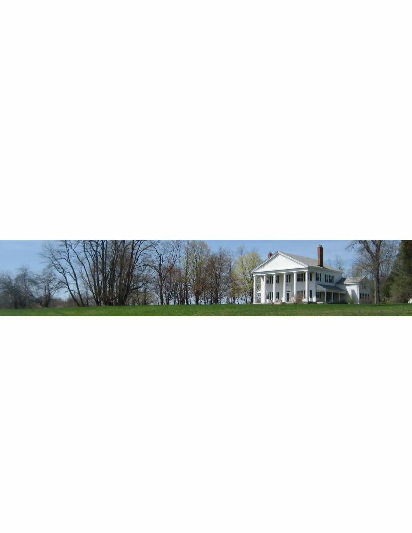
�


