129
DIMECC PUBLICATIONS SERIES NO.10 FINAL REPORT 2/2016 MANU – Future Digital Manufacturing Technologies and Systems 2012 – 2017
| Date post: | 11-Aug-2018 |
| Category: |
Documents |
| Upload: | nguyenthuan |
| View: | 217 times |
| Download: | 1 times |

FINAL R
EPORT 2/2016
MANU – Future D
igital Man
ufacturing Tech
nologies an
d System
s
DIMEC
C PUBLICATIONS
SER
IESNO.10
FINAL REPORT 2/2016
MANU – Future Digital ManufacturingTechnologies and Systems
2012 –2017

FINAL REPORT 2/2016
DIMECC PUBLICATIONS SERIESNO.10 2012 –2017
DIMECC MANU – Future Digital ManufacturingTechnologies and Systems

All rights reserved. No part of this publication may bereproduced, stored in a retrieval system, or transmitted,in any form or by any means, electronic, mechanical,photocopying, recording, or otherwise, without the priorpermission of DIMECC Oy.
Publisher DIMECC Oy Korkeakoulunkatu 7 33720 Tampere Finland www.dimecc.com
ISBN 978-952-238-176-7ISBN 978-952-238-177-4 (pdf)
DIMECC Publication series
ISSN 2342-2696 (online)
© DIMECC Oy
Graphic design and layout: Public Design Oy
Cover image: Jaakko Karjalainen, VTT
English language editor: Semantix Oy
Printed in Finland: Grano Oy, Tampere, 2016

FINAL REPORT 2/2016
CONTENTS
PREFACE Kalle Kantola: Nexus of Capabilities ......................................................................................................................................... 6 Kai Syrjälä: Integration of Research and Industry Challenges ......................................................................... 8
INDUSTRY REPRESENTATIVE’S REVIEW Juho Nummela: Ponsse PLC ......................................................................................................................................................... 11
RESEARCh INSTITUTES’ REVIEW Pentti Eklund: VTT Technical Research Centre of Finland Ltd ........................................................................... 13
DIMECC MANU IN A NUTShELL ................................................................................................................................................................. 15
1 DIGITAL MANUFACTURE AND FATIGUE OPTIMIZATION FOR SUPERIOR RELIABILITY (DIGFOSURE) ......................................................................................................... 16
Summary of the project’s motivation and achievements ............................................................................................... 16
Key results and impacts ............................................................................................................................................................................... 21
Case Meyer Turku ..................................................................................................................................................................................... 21
Case Mapvision ........................................................................................................................................................................................... 25
Case Sandvik Mining and Construction .................................................................................................................................. 26
Case Sandvik .................................................................................................................................................................................................. 29
Case LUT ............................................................................................................................................................................................................. 30
Further information ............................................................................................................................................................................................. 32
Results ........................................................................................................................................................................................................................... 32
2 FUTURE DIGITALIZATION SOLUTIONS FOR EFFECTIVE INDUSTRIAL VALUE CHAIN (DIGIMAP) .......................................................................................................................... 34
Summary of the project’s motivation and achievements ............................................................................................... 34
Key results and impacts ............................................................................................................................................................................... 35
Further information ............................................................................................................................................................................................ 39
3 PERSISTENT BUSINESS TRANSFORMATION WITH PRODUCT KNOWLEDGE AND LIFECYCLE MANAGEMENT (PROMAGNET) ............................................... 42
Summary of the project’s motivation and achievements ............................................................................................... 42
The context of the ProMaGNet project .............................................................................................................................................. 44
The goal of ProMaGNet ................................................................................................................................................................................... 45
Implementing PLM for low volume manufacturing .............................................................................................................. 47

Capturing and reusing knowledge on high variety products ........................................................................................ 50
Updating and maintaining product knowledge throughout product lifecycle ............................................... 53
Utilizing state-of-the-art digital methods for product representation and documentation ............. 55
Sharing and using product knowledge in manufacturing networks ..................................................................... 61
Further information ............................................................................................................................................................................................ 64
4 ACCELERATING TIME TO PROFIT (ACCELERATE) ......................................................................................... 68
Project’s motivation ............................................................................................................................................................................................. 68
Summary of main achievements ........................................................................................................................................................... 69
Continuous learning and capability development .................................................................................................................. 71
Integrated development process ............................................................................................................................................................ 73
Fitted products and items .............................................................................................................................................................................. 76
Efficient systems .................................................................................................................................................................................................... 80
Collaboration .............................................................................................................................................................................................................. 86
Further information ............................................................................................................................................................................................. 86
5 DIGITALIZING OF YOUR FACTORY FLOOR (LEANMES) .......................................................................... 87
Summary of the project’s motivation and achievements ............................................................................................... 87
Key results and impacts ............................................................................................................................................................................... 88
At the root: digitalizing manufacturing operation management with the LeanMES concept ........... 89
Strong branches – standardizing the communication interfaces ............................................................................. 90
New leaves – from Excels and post-it notes to fully digitalized manufacturing ......................................... 92
Fastems’ main results ........................................................................................................................................................................... 99
Konecranes Agilon’s main results ............................................................................................................................................ 100
Finn-Power’s main results .............................................................................................................................................................. 101
Delfoi’s main results .............................................................................................................................................................................. 102
Logistic’s main results .......................................................................................................................................................................... 102
Ponsse’s main results ........................................................................................................................................................................... 103
hT-Laser’s main results ...................................................................................................................................................................... 104
Further information ............................................................................................................................................................................................. 105

5
6 EMERGING TECHNOLOGIES TOWARDS ADDITIVE MANUFACTURING, SUSTAINABILITY AND SMART FACTORY
TASK 1 ADDITIVE MANUFACTURING ............................................................................................................................................... 107
Summary of the project’s motivation and achievements ............................................................................................... 107
Key results and impacts .................................................................................................................................................................................. 108
1. Industrial cases .................................................................................................................................................................................... 108
2. Practical guidebook .......................................................................................................................................................................... 110
3. Studies of large component manufacturing ............................................................................................................... 111
Further information ............................................................................................................................................................................................. 112
TASK 2 VISUALIZATION OF SUSTAINABILITY KEY PERFORMANCE INDICATORS 2013–2015 ... 115
Summary of the project’s motivation and achievements ............................................................................................... 115
Key results and impacts .................................................................................................................................................................................. 116
Further information ............................................................................................................................................................................................. 117
TASK 3 SMART FACTORY 2015–2016 .............................................................................................................................................. 119
Summary of the project’s motivation and achievements ............................................................................................... 119
State of the art ....................................................................................................................................................................................................... 120
Smart Factory concept – Generation of new ideas ................................................................................................................. 121
Smart Factory pilots ............................................................................................................................................................................................ 124
Further information ............................................................................................................................................................................................ 127

6
DIMECC’s MANU program preparation work was initialized in 2011with the aim of boosting digitalization in the Finnish manufactur-ing industry. The preparation work was carried out through inten-
sive co-operation with the leading manufacturing companies and vision-ary researchers. The program plan, with prioritized activities, was intro-duced in 2012.
In 2011, our counterparts in Germany had the same kind of initiativeon their hands, and the term Industry 4.0 was first used at the HannoverFair in 2011. In 2012, the working group on Industry 4.0 presented a setof In-dustry 4.0 implementation recommendations to the German fed-eral government.
Today, both of these initiatives are acknowledged as the leading pro-grams in the European Commission’s “Digitizing European Industry” ini-tiative. More importantly, however, the importance of digitalization iswidely acknowledged within the manufacturing industry, and we canwidely see the concrete business benefits behind digitalization-relatedbuzzwords.
These journeys have not been easy ones, but required a nexus of rightcapabilities, meaning interdisciplinary co-operation among the right ex-perts from industry and research. In both cases, this co-creation has hada strong industry commitment, which has ensured the impact of the re-sults. In addition, the public authorities have supported the work by en-suring an environment for risk-taking and the wide promotion of the im-portance of digitalization.
I want to warmly thank the whole DIMECC MANU team for their greatwork in the program. I would especially like to acknowledge the effortsof the program preparation team for their visionary work, the programmanager Dr. Kai Syrjälä for his effort in enabling effective co-operation,and Tekes for the funding of this work.
PREFACE
Nexus of Capabilities

7
DIMECC MANU’s recipe for success, meaning the nexus of necessary ca-pabilities, has shown its effectiveness, and it can also be used in the fu-ture. In Finland, we have leading ICT and industry capabilities, and thusan exceptional possibility to lead industrial digitalization on many fronts.If Finland uses the power of co-operation effectively, the Finnish initia-tives will also be noted among the world-leading ones in the future.Please keep this in mind while reading this final report and the great re-sults achieved.
Dr. Kalle Kantola
CTODIMECC Ltd.
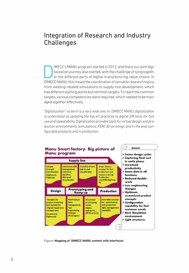
Integration of Research and IndustryChallenges
DIMECC’s MANU program started in 2012, and there our joint digi-talization journey also started, with the challenge of tying togeth-er the different parts of digital manufacturing value chains. In
DIMECC MANU, this meant the coordination of versatile research topics,from welding-related simulations to supply-line development, whichhad different starting points but common targets. To reach the commontargets, various competencies were required, which needed to be man-aged together effectively.
“Digitalization” as term is a very wide one. In DIMECC MANU, digitalizationis understood as updating the top art practices to digital SW tools for fastuse and repeatability. Digitalization provides tools for virtual design and pro-duction environments (simulations, FEM, 3D-printing), and in the end, con-figurable products and in production.
Figure: Mapping of DIMECC MANU content with interfaces
8

From a business point of view, the final goal was to streamline processesfor improved productivity. A lot of non-value-adding work like manual“spread-sheet operations” can be discarded, while fewer errors in oper-ations and online visibility inside projects across company borders havebeen achieved.
In DIMECC MANU, set interfaces (see figure) and ambitious stream-lined goals with industry partners were turned into research objectivesand new practices. New research results and practices were then trans-formed into digital form.
The Industry 4.0 initiative has been strongly developed in Germany.However, it cannot be directly applied to Finnish industry. Digital modelsfor optimization of production lines target the fastest break-throughtimes for production. This is a big driver for the car industry as, for exam-ple, a 1% cost reduction is meaningful if 60 million brake disks are ma-chined. Finnish industry, however, consists of companies producinghighly customized products and project-based machinery deliverieswithout the benefits of mass production. DIMECC MANU is hitting this is-sue. We have developed fast supply lines with customized digital soft-ware, updated product data management for product ramp-up, effec-tive material flow for components, metal 3D-printing applications forplastic molds, and even copper-based machine components with heattreatments. All of these actions have had one ultimate goal: a novelSmart Factory, which means smart design, effective manufacturing,and agile operations.
Smart Factory thinking and the combination of research results, to-gether with teamwork, have been a success. Workshops in DIMECCMANU companies have created development plans and focused invest-ment plans. A remarkable increase in business has been achieved. Thelesson learned is that access to new technology, like robotics, is easilyavailable for Finnish SMEs, but they need to take brave, risky decisionsto invest in digitalization. Time is money, also in investment planning!
World-class production technology (welding, CNC milling, assembly,3D-printing) and full digital product and production definitions for ma-chining in factories are the key drivers for the success of manufacturingbusinesses. We have examples of the successful progress of companiesin DIMECC MANU like Ponsse, Metso Minerals, and Raute, just to mentiona few.
However, the digitalization journey is not over, and research in thisarea needs to be pushed! Short-term implementation in SMEs is impor-tant. Several companies have low volumes and low profitability that canbe radically improved by digital solutions. Collaboration between re-search units and SMEs in Finland has turned out to be a success storyin DIMECC MANU. SMEs have limited resources for research and digitaldevelopment.
9

It has been a pleasure to be in the DIMECC MANU team! DIMECC MANUcan share a lot of brand-new research results, more than 100 publica-tions, and a lot of digital applications implemented in DIMECC MANU pro-grams. We have created a foundation for digitalization in Finnish industry.Therefore, I give my warm thanks to all those who have been involved tomake DIMECC MANU happen, sincerely.
Dr. Kai Syrjälä
DIMECC MANU Program ManagerSenior ConsultantKaidoc Ltd
10

11
STAKEHOLDERS’ PERSPECTIVESIndustry representative’s review
Ponsse PLC
It has been a great privilege to participate in the DIMECC MANU pro-gram as a representative of one of several Finnish industrial forerun-ner companies. The program has been a good example of our national
capabilities in bringing challenging visions to life as concrete supportfor daily work in today’s global competition. In DIMECC MANU, the vitallyimportant rapid introduction of new ideas and ways of working hasbeen enabled by seamless collaboration between companies, universi-ties, and research institutes. For the participating companies, collabo-ration has made it possible to tackle more complicated and riskier prob-lems than the companies could have dealt with by themselves. For theparticipating universities and research institutes, on the other hand,DIMECC MANU has provided a world-class industrial platform on whichto test and implement next-generation ideas and solutions in a real-lifeenvironment. The quality of the achieved results has further been en-hanced through effective cross-learning among the participating com-panies, as well as among all the implemented projects. DIMECCMANU’s concept of accumulating knowledge and know-how hasproven to be highly successful.
In DIMECC MANU, digitalization has shown its true value in speedingup processes, as well as in cutting waste and costs through improvedexcellence in all operations. With modern digital tools, a larger numberof realization alternatives can be analyzed before even the smallest partof the product or service has been concretely realized. Among other tools,modeling and simulation, optimization, virtual and augmented reality,and testing have improved the competitive edge of DIMECC MANU par-ticipants.
Similarly, modern digital systems bring more knowledge to deci-sion-making. The lessons learned from earlier designs and productioncan be stored and reused when building solutions according to new cus-tomer needs. More silent knowledge can be formulated as guidelines, tobe used in design for manufacturing and assembly. This evolution makes

the companies less vulnerable to knowledge loss, such as in cases ofcompany acquisitions or personnel arrangements.
This concerns not only the capabilities of the OEM company, but alsothe capabilities of the whole supply and delivery network. When digital-ization is used in an intelligent way, the requirement to make things “firsttime right” in the whole network can be repeatedly fulfilled. In practice,this is the only possible way to operate profitably.
To keep the competitive edge acquired in DIMECC MANU, the nextsteps need to be taken promptly. Tomorrow already begins today. Enjoythe journey!
Juho Nummela
President and CEO, DSc (Tech)Ponsse PLC
12

13
I had the honor of preparing the DIMECC MANU program togetherwith a working group chaired by director Juhani Rantalainen fromFastems Oy Ab. The task given was to bring together at least 15 com-
panies and several research institutes with the common goal of in-creasing the competitiveness of the Finnish manufacturing industry bymeans of digitalization. However, the interest within the industry waseven bigger than expected, and the final number of companies partici-pating in DIMECC MANU was more than 30. Several good proposals hadto be rejected or cut in volume in order to keep the size of the programwithin reasonable limits. For research institutes, this high level of inter-est from industry made working in DIMECC MANU, of course, very moti-vating. This is certainly one explanation for the high-level resultsachieved in DIMECC MANU, both from industrial and scientific points ofview. DIMECC MANU was an excellent example of a working public–pri-vate partnership in research.
The topics of DIMECC MANU covered different aspects of digitaliza-tion of manufacturing, including digital tools to manage and optimizemanufacturing processes, as well as information flow in manufacturingnetworks and in manufacturing execution systems. For a researcher, ithas been very rewarding to see the research results being demonstratedby or even implemented in industry. Among other achievements, the DIG-FOSURE project demonstrated a cell with camera-based automated in-spection technology for low-volume, complex geometry welding produc-tion. The DigiMAP project developed an optimization tool for the designand manufacture of high-strength steel structures. In ProMaGNet, a goodexample is a customized product data management (PDM) system thathas been brought into industrial use. In the ACCELERATE project, a digitalsystem for the management of the supply line and supplier network hasbeen developed and implemented with good results. The Lean MES proj-ect demonstrated LeanMESsenger, a tool for the dynamic allocation oftasks to available and capable workers.
RESEARCH INSTITUTE’S REVIEW
VTT Technical Research Centre of Finland Ltd

The DIMECC MANU program has had close links to other relevant re-search initiatives, which has further increased its impact. A good exam-ple is the DIGFOSURE project, where a broad researcher exchange withSouth Korea, in the field of the simulation of welding, has taken place inclose co-operation with VTT’s FiDiPro project.
An interesting feature in DIMECC MANU has been the Next Genera-tion Manufacturing project, where only research institutes were fundedand where the research topics were decided separately for each fundingperiod. This gave, on the one hand, a certain freedom to researchers, andon the other hand the flexibility to react to the fast-changing technologyand needs of industry. For the first funding period, the topics chosen wereadditive manufacturing (AM) or 3D printing, and sustainability perform-ance indicators. AM, in particular, turned out to be an excellent choice, asduring DIMECC MANU the printing of metal components developed froma laboratory method to an industrial process. AM remained as a researchtopic for the whole duration of DIMECC MANU, while sustainability was,in the last funding period, replaced by Smart Factory, which summarizedthe results of DIMECC MANU in four workshops and in a handbook cov-ering different aspects of the research carried out during the program.
The good co-operation between industry and research institutes thattook place in DIMECC MANU will continue within DIMECC and also in oth-er contexts. Several proposals based on DIMECC MANU projects havebeen submitted or are under planning both at national and at Europeanlevel. Some may even say that the rise of DIMECC is a continuum ofDIMECC MANU, since digitalization has proven to be the primary technol-ogy change driver in manufacturing industries.
Pentti Eklund
Principal Scientist, VTT Technical Research Centre of Finland Ltd
14

15
Company partners (Pcs.): ...................................................................................... 35
Research institution partners (Pcs.): ................................................................. 6
Volumes
Duration: . . . . . . . . . . . . . . . . . . . . . . . . . . . . . . . . . . . . . . . . . . . . . . . . . . . . . . . . . . . . . . . . . . . . . .01.10.2012 – 31.12.2016
Budget: ............................................................................................................... 22,2 M€
Company budget: ............................................................................................... 12,2 M€
Research institution budget:.......................................................................... 10,0 M€
People involved ........................................................................................................... 145
Results:
Number of publications: ...........................................................................................122 Number of doctoral theses: 7 finished and 6 under work, unfinished
by end 2016Number of other theses:........................................................................................... 31
Patents and invention disclosures: wide portfolio inside companies, not shared to consortium
New software products: ........................................................................................... 5
Research exchange months:................................................................................... 88
New commercial software products.................................................................... 5
Volume of spin-off projects ............................................................................... 50 M€
Enabled business potential (estimate):................................................... 1 Billion €
DIMECC MANU IN A NUTShELL

16
FINAL REPORT 2/2016
PROJECT NAME
DIGFOSURE P1Mika Sirén/VTT Ltd
Tero Lokasaari /Wärtsilä Energy Solutions
Background and motivation
There is a clear need to shorten the design and development timespans of new products in the Finnish machinery industry. One wayto shorten the time to market or profit is to introduce modern inte-
grated digital design tools to support the machinery industry’s productdesign and development. One area in particular in which this needemerges is the fatigue design of welded machinery structures with along service life and high structural and operational reliability require-ments. The importance of fatigue behavior optimization is further em-phasized by recent structural material developments, such as the intro-duction of novel steel grades, and the related attempts at lightweight ma-chinery solutions. The resulting smaller sheet thickness enables the useof laser-based welding processes for a further productivity increase, butalso introduces distinct features in structural behavior.
The manufacturing parameters in the welding process can be opti-mized according to productivity and quality. The conditions for enhancedproductivity can be created with the aid of design, for example by meansof optimizing the weld geometry, welding process, position, and accessi-bility. Quality is proportional to the weld performance in conditions ofuse. In manufacturing, productivity and quality are not mutually contra-dictory, and with successful optimization, good quality can be achievedefficiently and profitably. To optimize both productivity and quality simul-taneously, the product and production requirements must be properlycontrolled in such a way that the quality is allocated appropriately towhere it is needed, and the features it entails in each particular case aredefined.
An answer to the above demands is an integrated simulation andanalysis approach covering the entire design chain, from the welding
Summary of the project’s
motivation andachievements
Digital Manufacture and Fatigue Optimization for Superior Reliability

17
process, resulting in metallurgical properties, weld geometry, residualstresses and distortions, to fatigue strength and eventually the life-cyclecharacteristics of the welded structure. However, the vast amount of da-ta involved in the above also requires modern data-processing tools totransfer the relevant key data from the design office along the valuechain to the (often remote and/or subcontracted) production. In the oth-er direction, reporting the quality control and assurance data, possiblytopped with production technology information from the subcontractorshop floor back to the relevant OEM parties (assembly, delivery), and fur-ther to service and/or after-sales, is also vital for fluent and efficient pro-duction and use.
Modern welding simulation software tools provide the means forcalculating accurately the welding deformations and residual stressstate resulting from a particular welding procedure. The results can beused further, either as source data for fatigue analysis and design,and/or for optimization of welding procedures and sequences for pro-ductive welding fabrication. Coverage and digital processing of the inter-dependencies between the welding process and parameters and the re-sulting weld fatigue properties in simulations is a major challenge in thefatigue design and simulation of a welded structure. This requires thediscovery and use of the interactions between the welding process andthe resulting weld geometry, and further between weld geometrical fea-tures and fatigue strength, and eventually use and service-life charac-teristics.
Project achievements (partner specific)The main project breakthrough for the marine and shipbuilding industry,including companies such as Meyer Turku, was the development at Aalto University of the basis for a new fatigue characterization methodthat is suitable for high-quality weld profile measurements and digitalmanufacturing. The method is applied to the fatigue strength analysis oflaser-hybrid welded joints used in, for example, ship deck structures.This work has novelty, since it is the first time that the real weld geome-try on a microscale has been successfully considered directly in the fa-tigue strength assessment of welded joints.
Using robots in automotive industry production lines is a key con-tributor to keeping European car manufacturers competitive againstthe threat caused by cost pressure from Far East manufacturers. Au-tomation is not limited to manufacturing and welding, but quality controlis also more and more done automatically using special measurementunits. However, the products are complex, and multiple different cartypes are built on the same production line. There is no additional time torecalibrate the measurement systems or do manual work on movingparts in the quality-checking units. VTT and Mapvision together devel-

oped a robotic control unit, machine vision system, and algorithms tocheck if the holds, welds, and bolts are exactly in the right place com-pared to the CAD drawing of the part. The robotic unit was optimized tofollow the welding path in the component design and to make the neces-sary corrections online.
Numerical and analytical methods can be used to predict the quali-ty of welded structures. The aim of the simulation studies at VTT was toevaluate the possibilities to use mathematical methods for weldingprocess optimization. The study also includes evaluation tests related totransferring Sysweld simulation results into other commercial FEA pro-grams, in order to evaluate the effect of residual stresses on fatigue. Thetests show that the two programs can be used together to aid optimiza-tion of the welding process. The use of numerical methods requires anextensive amount of work and also includes time-consuming heat-source calibration. Although there are programs available on the mar-ket that calculate the heat input model automatically, they are usually re-stricted to specific processes. Even if the use of numerical methods re-quires extra resources, the work is justified, at least in complicated cas-es and when quality is the primary concern.
The results show that analytical methods can be used for first esti-mation of, for example, cooling rates and microstructures in welding.These methods are easy to use and help in the work of specification ofoptimal welding parameters. They can be used to define first estimatesof process parameters for simple welding cases (Figure 1).
Figure 1.Martensite phase fraction in the arc welded T-joint, calculated usingSYSWELD (steel S355J2G3)
One of the main targets set for the program by Keslawas to study and de-termine welding parameters for high-strength steels in forest machin-ery manufacturing, in collaboration with LUT, and to encourage productdesign and manufacturing co-operation in the case of high-strengthsteel product manufacturing. The parameter studies were found to bequite successful: critical factors for fatigue durability could be improved
18

19
by managing and avoiding fatigue cracks, as well as finishing welds, un-dercuts, and geometries. However, the design aspects were more chal-lenging. It was difficult to manage thin walls without deformations inmanufacture. This requires more work on optimizing construction suchas wall thickness and welds, design for manufacturing, (robot) welding,machining, assembly, and digitalized document management such aswelding specifications, instructions, and feedback.
During this project, Kesla Oyj created design and manufacturing in-structions for HSS welding. The stress level of the weld-structured mainbooms of a crane were measured during field tests. Weld tests were ex-ecuted in co-operation with material manufacturers. Alternative manu-facturing methods for profiles have been taken into account when se-lecting steel profiles for forest machinery manufacturing. The Master’sthesis “Development of the manufacture of a telescopic boom” wasmade together with LUT.
Figure 2. Novel Kesla UHSS truck crane boom (left) and the final product in operation (right)
For SSAB, the purpose of this project was to define relations between al-loying of steels, microstructure, and the mechanical properties of theheat-affected zone (HAZ), as well as the used weld metal, and to applythat information in a simulation tool that would estimate the weld me-chanical properties based on base material, welding parameters, andthe filler material. The steels investigated together with the University ofOulu were ultra-high strength steels (UHSS) in strength classes 960MPa and above. Furthermore, the target was to find out the best alloyingcombination allowing good toughness properties of HAZ/weld metaland matching weld. The Digfosure project has enabled the design of ultra-high strength steels that have enhanced weldability, and the new data pro-duced within the project has been added to the simulation tool, thus im-proving its performance.

Data analyses and thermomechanical Gleeble welding simula-tions have been carried out for the MAG welded project steels (Strenx1100 MC and S1300) to model different heat-affected zones with differ-ent cooling rates. The results show that Strenx 1100 MC and S1300 haveexcellent toughness in HAZ, and they both fulfilled the 14 J impact valuerequirement for a specimen of 5 mm with 5 s and 10 s t8/5 times at -40°C. Gleeble results confirmed this excellent toughness of the projectsteels. Contrary to toughness in HAZ, both of these welded steels had asignificant drop in strength from base metal to HAZ. The reasons are lowfiller metal strength and softening of HAZ, which is normal at thesestrength levels.
Additionally, some welding experiments were performed usingmodern welding methods like laser and laser-MAG hybrid welding, toget information about static and dynamic properties of welds and com-pare the achieved results to the joints welded with a conventional MAGwelding process. In this case, both the matching and under-matchingfiller materials were used. The results showed that, in this case, fatigueis not dependent on the welding method, but the geometry of weld is thedominant factor.
The Wärtsilä Energy Solutions target was to develop scientificallybased state-of-the-art engine-generator set steel structure fatigue- dimensioning criteria. Engine sizes and outputs are rising and fatiguedesign is becoming highly critical in engine-generator set applications.During the project, fatigue tests were carried out at Tampere Universityof Technology (TUT) for the base frame sub-model, and fatigue dimen-sioning instructions and a fatigue test device were developed.
The first main results were experimental fatigue tests for a baseframe sub-model in the TUT laboratory for S235 and S355 steel grades.Comparison of the experimental and FE analysis results showed thatthe FE analysis predicts fatigue-critical locations correctly, and fatiguedurability can be estimated based on analysis.
The second main achievement was a fatigue dimensioning guide-line that enables engine-generator welds to be dimensioned using FEanalysis and virtual 3D models. Even measured 3D geometry can beused. Fatigue dimensioning instructions were utilized for the Wärtsilä18V50SG B-stage engine base frame: the frame design was upgradedand new manufacturing drawings were prepared based on the analysis.Instructions were also utilized successfully, as field repairs were madeto the 20V46F at Maracanau power plant in Brazil, which was sufferingfrom fatigue issues.
The third major achievement was an in-house ultra-high cycle testfacility developed at the Wärtsilä laboratory. The first preliminary testshave been completed to verify that the test system functions. Thesetests have already indicated important factors contributing to fatigue
20

21
durability in the high-cycle fatigue region. Not all the planned tests canbe completed during this project. However, the developed fatigue testarrangement gives great possibilities to improve fatigue dimensioningin the future.
Developments in the project have increased fatigue dimensioningknow-how greatly and have provided tools for designing new productsat a detailed level. This know-how also serves as a great tool for field re-pairs. The future plan is to develop a new engine-generator set baseframe concept based on the improved know-how. Another future step isto utilize the in-house ultra-high cycle test facility for testing, to improvefatigue dimensioning criteria based on test results, and finally to updatethis expertise in the fatigue dimensioning instructions.
Three different loader boom concept designs were created andevaluated by Sandvik Mining and Construction. Lay-out and final design,as well as FEA, were done for these concepts, and three prototypebooms were manufactured using different welding methods. A benchtest by LUT and field tests were completed, and the results from the FEA,bench test, and field tests were compared. The key results are a 700 kgweight saving (–25%, target –30%) and the targeted life-time achievedfor prototypes, but it is not yet possible to show product cost savings (tar-get –20%). However, the new boom concept has reduced the number ofparts and the amount of welding measured in kilos.
The Digfosure project work has been carried out in close co-opera-tion with different companies and research institutes: one of the greatachievements has been contacts between technical experts in differentcompanies and research institutes through this project. Project man-agement pushed communication toward open sharing, and meetingswere even arranged between technical experts, to share their expertiseon specific topics.
CASE MEYER TURKU: Thin deck structure provides better energy efficiency and increased payload
Ingrit Lillemäe, Sami Liinalampi, heikki Remes (Aalto),
Antti Itävuo, Ari Niemelä (Meyer Turku)
To build more energy-efficient large steel structures such as cruise ships,new lightweight solutions are needed. Smaller plate thicknesses thanthe currently considered limit of 5 mm could be utilized in some parts ofthe structure, if modern production technologies, such as laser-hybridwelding, are utilized. However, the lack of knowledge about fatigue re-sistance, in addition to buckling, vibration, and manufacturing consider-ations, is preventing the rules and recommendations from allowing theuse of thin plates in large steel structures. The main challenges related
Key resultsand impacts

to large thin-plate structures are caused by their welding-induced dis-tortions. Due to the low bending stiffness of the plate itself, the distortionshapes and resulting structural behavior are different from thick plates.Therefore, traditional fatigue assessment approaches do not describethe fatigue strength of thin structures accurately. In addition, thin platesare more sensitive to the geometrical properties of the weld and requirea more advanced fatigue characterization method. When laser-hybridwelding with properly optimized welding parameters is utilized, reducedinitial distortions and smooth weld geometry are possible, resulting inhigh fatigue strength. However, in order to transfer the fatigue test re-sults to fatigue design, the behavior of a larger thin structure also needsto be understood. In a stiffened panel, considerable distortion occurs inboth directions on the plate surface, and in the surrounding plates, stiff-eners and girders redistribute the loads.
In this case Meyer Turku, a fundamental understanding of the fa-tigue behavior of thin deck structures and a technologically feasible so-lution for thin deck manufacturing was developed. For the first time, theresponse and fatigue strength of a thin full-scale laser-hybrid weldeddeck structure under realistic loading, similar to hull girder bending, wasstudied experimentally and numerically. Both small- and full-scale spec-imens were cut from the same thin deck panels. The dimensions of thestiffened panel represent a typical ship deck structure, and the weld qual-ity reflects a typical shipyard manufacturing process (see Figure 3). Thindeck panels were produced by Meyer Turku shipyard and Winnova Oy.
Figure 3. Full-scale thin deck structure, full- and small-scale specimen, andmacrograph of a laser-hybrid welded butt joint with smooth weld geometry
Experimental and numerical investigations were carried out by AaltoUniversity, while the University of Oulu supported the weld geometrymeasurements on a micro-scale. The experiments with thin deck struc-tures included accurate optical geometry measurements and fatiguetesting under axial tension loading. The amount of initial distortion nearthe fatigue-critical butt joint was up to 4 times smaller than previouslyreported for thin arc-welded navy vessel panels. However, even if thedistortion is small, the shape still has a significant influence on the struc-
22

23
tural stress. The measured distortion shapes were applied to finite ele-ment (FE) models, and a geometrically nonlinear analysis was per-formed to calculate the stresses and strains. The results revealed thatwhen initial distortion and geometrical nonlinearity are properly consid-ered, the FE results agree very well with the experiments (see Figure 4),which is rare for full-scale tests. In addition, the fatigue strength in termsof structural hot-spot stress is on the same level for both full-and small-scale specimens, the scatter is low, and the SN curve slope is close to m= 5 (see Figure 5). The measured fatigue strength is considerably higherthan the IIW structural stress design curve, indicating that high fatiguestrength is achievable in full-scale structures when manufacturing andweld quality is high.
Figure 4.Normal strain from FE analysis and experiments on the fatigue-criticalside of the weld
The successful panel test and numerical analysis, completed in theDIMECC MANU project, is a crucial step in long-term development workfor thin ship structures (see Figure 6). The previous EU-funded BESSTproject provided an understanding of the fatigue strength of weldedjoints, to define requirements for good-quality welding. This knowledgeis utilized in this project and thereby will provide an understanding of thefatigue behavior of a full-scale structure, which is a starting point for thenext step, to build a prototype block structure in a new TEKES project.This is necessary before the final application becomes feasible for an actual cruise ship. The goal for the implementation of the final applica-tion in a cruise ship is about 2025.

Figure 5. Fatigue test results in terms of structural hot-spot stress range
Figure 6. Progress of research and development work for thin deck ship struc-tures, from welded joints to final product
RELATED KEY PUBLICATIONS:
Lillemäe, I. Fatigue assessment of thin superstructure decks, Doctoral dissertation, Aalto University, 2014
Lillemäe, I.; Remes, H.; Liinalampi, S.; Avi, E.; Romanoff, J. Influence of welding distortion on the structural stress in thin deck panels, PRADS 2016,4–8 September 2016, Copenhagen, Denmark.
Lillemäe, I, Liinalampi, S, Remes, H, Itävuo, A, Niemelä, A. Fatigue strength of thin laser-hybrid welded full-scale deck structure, submitted to Inter -national Journal of Fatigue in August 2016.
Liinalampi, S, Remes, H, Lehto, P, Lillemäe, I, Romanoff, J, Porter, D. Fatiguestrength analysis of laser-hybrid welds in thin plate considering weld geometry in microscale, International Journal of Fatigue, 2016; 87: 143–152.
Lillemäe, I, Remes, H, Liinalampi, Itävuo, A. Influence of weld quality on thefatigue strength of thin normal and high strength steel butt joints. Weldingin the World, 2016; 60:731–740.
24

25
CASE MAPVISION: Robot welding unit with full digital measurement data
Antti Knuuttila, Matti Kutila
Tolerance in automotive parts varies in different parts of the components.The bolt holes need to be in the right place with a better than 1 mm ac-curacy. However, the component dimensions may allow more than 5 mmvariations without causing rejection. This directly influences the weldingaccuracy of the components, to ensure that welding follows the designedtrack within sub-pixel accuracy (see Figure 7). An innovative robot weld-ing unit with full digital measurement data was developed under theDIMECC MANU program. The developed solution brings the quality check-ing of weld profiles in automated production systems into the digital era,creating prerequisites for high productivity and quality welded structuremanufacturing.
Almost all fabrication of metal structures today involves welding.Fatigue is a major cause of failure, especially in welded structures, re-flecting the fatigue performance of welded joints. Whether welding to-gether a few relatively simple parts or fabricating large, complex struc-tures, weld fatigue is one of the most common failure modes if the partor structure is subjected to fluctuating stresses. Therefore, the qualityof welds is a top priority for manufacturers, especially in the automotiveindustry.
Figure 7. Mapvision quality gate and the robot cell working in a VTT laboratory
A robot welding unit tackling the challenges of weld quality was devel-oped in the DIMECC MANU program. In the solution, the robotic controlunit, harnessed with a machine vision system and algorithms, checks ifthe welds, holds, bolts, and other structural details are exactly in theright place compared to the CAD drawing of the part. There is an adaptivefeedback loop from the control unit to the robot welding unit, and neces-sary corrections can be made online.
The developed solution brings the quality control of weld profiles inautomated production systems into the digital era. The solution enablesadaptive correction of the welding parameters (e.g. corrections in weld-ing path or parameters) to realize a weld with the desired geometry to

fulfil the high quality and fatigue strength requirements. Current solu-tions just check the component, and if there is a welding failure, the com-ponent is rejected. This causes a huge number of material and produc-tion losses.
An automated operator-free robot welding solution also improvessignificantly the efficiency of production lines, offering a competitive ad-vantage to the Finnish manufacturing industry. For example, in the auto-motive industry, which is one of the target segments of the developed solution, robotization is a key contributor in keeping European car man-ufacturers competitive against the threat caused by cost pressure com-ing from the Far East. In addition to manufacturing, quality control alsohas to be done automatically by a special measurement unit. The prod-ucts are complex and multiple different car types are built on the sameproduction line. There is no additional time to recalibrate the measure-ment systems or to do manual work to move parts to the quality-check-ing units. Therefore, automated quality control and inspection systemsare needed.
The solution creates prerequisites for high productivity and qualitywelded structure manufacturing. The benefits of the developed solutioncan be counted in savings in material and production losses, and im-proved productivity. Automated quality assurance in the automotive in-dustry has a significant impact by reducing the risk of calling back carsdue to failures in suspension systems. In the case of call-back cases, thelosses are counted in tens of millions euros.
Quality is proportional to the weld performance in the conditions ofuse. With the developed solution, the resulting product service proper-ties can be ensured reliably and accurately. As a result, costs arisingfrom poor quality, such as reclaim, scrap, and downtime costs, can beminimized. For Mapvision, the manufacturer of the online visual inspec-tion solution, this means an additional competition factor in automotiveproduction line bidding.
CASE SANDVIK MINING AND CONSTRUCTION: Speeding up the newproduct development process with digital fatigue strength simulationtools
Arto Vento, Jarkko Laine
There is a need to shorten the design and development time-spans ofnew products in the Finnish machinery industry. One way to shorten thetime to market is to introduce modern integrated digital design tools tosupport the machinery industry’s product design and development. As aresult of the development work done under the DIMECC MANU program,new digital fatigue strength verification methods and concepts were de-veloped.
26

27
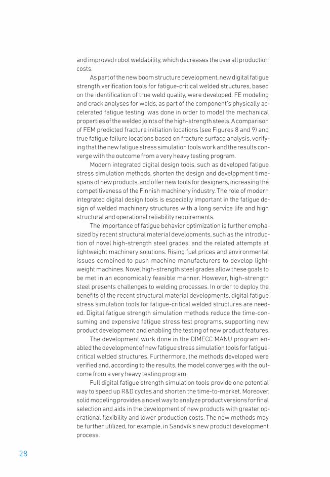
Figure 8. Fatigue test of the boom structure in laboratory of Steel Structures at LUT and simulation model for the same structure
Figure 9. Simulation and FE-model for the tested boom structure
An area where the need for integrated digital design tools emerges par-ticularly is the fatigue design of welded machinery structures with along service life and high structural and operational reliability require-ments. An understanding of the fatigue of welded structures is especial-ly important in the case of novel high-strength steel grades, as advancedhigh-strength steels would bring significant benefits for machinery interms of lighter and harder structures. But at the same time they pres-ent challenges for welding processes. As a result of the developmentwork done in the DIMECC MANU program, new digital fatigue strengthverification tools for welds were developed.
In the DIMECC MANU program, a new boom structure utilizing high-strength steel and new welding methods was designed. The successfulintroduction of a high-strength steel material into a boom structure enabled lighter, stronger, and more efficient equipment with higher pay-loads and lower fuel consumption. Lightweight boom construction, usinghigh-strength steel material, enormously reduced the structural deadweight and increased the lift capacities. The total weight saving was 700kg, which is 25% of the boom structure mass. The new boom structurehas also reduced the number of parts, resulting in fewer welding kilos
and improved robot weldability, which decreases the overall productioncosts.
As part of the new boom structure development, new digital fatiguestrength verification tools for fatigue-critical welded structures, basedon the identification of true weld quality, were developed. FE modelingand crack analyses for welds, as part of the component’s physically ac-celerated fatigue testing, was done in order to model the mechanicalproperties of the welded joints of the high-strength steels. A comparisonof FEM predicted fracture initiation locations (see Figures 8 and 9) andtrue fatigue failure locations based on fracture surface analysis, verify-ing that the new fatigue stress simulation tools work and the results con-verge with the outcome from a very heavy testing program.
Modern integrated digital design tools, such as developed fatiguestress simulation methods, shorten the design and development time-spans of new products, and offer new tools for designers, increasing thecompetitiveness of the Finnish machinery industry. The role of modernintegrated digital design tools is especially important in the fatigue de-sign of welded machinery structures with a long service life and highstructural and operational reliability requirements.
The importance of fatigue behavior optimization is further empha-sized by recent structural material developments, such as the introduc-tion of novel high-strength steel grades, and the related attempts atlightweight machinery solutions. Rising fuel prices and environmentalissues combined to push machine manufacturers to develop light-weight machines. Novel high-strength steel grades allow these goals tobe met in an economically feasible manner. However, high-strengthsteel presents challenges to welding processes. In order to deploy thebenefits of the recent structural material developments, digital fatiguestress simulation tools for fatigue-critical welded structures are need-ed. Digital fatigue strength simulation methods reduce the time-con-suming and expensive fatigue stress test programs, supporting newproduct development and enabling the testing of new product features.
The development work done in the DIMECC MANU program en-abled the development of new fatigue stress simulation tools for fatigue-critical welded structures. Furthermore, the methods developed wereverified and, according to the results, the model converges with the out-come from a very heavy testing program.
Full digital fatigue strength simulation tools provide one potentialway to speed up R&D cycles and shorten the time-to-market. Moreover,solid modeling provides a novel way to analyze product versions for finalselection and aids in the development of new products with greater op-erational flexibility and lower production costs. The new methods maybe further utilized, for example, in Sandvik’s new product developmentprocess.
28

29
CASE SANDVIK: Comparison the notch stresses between idealized andtrue weld shapes
Antti Raskinen, Timo Björk
The comparison between idealized and true weld geometry was carriedout in terms of ENS (effective notch stress) method. The analyzed coverplate is a part of the boom structure presented in previous case Sandvik.The results from analyses carried out by Antti Raskinen at LUT areshown in Figure 10.
(a)
(b)
(c)
Figure 10. (a) Idealized (left) and true (right) FE-model of the detail(b) ENS stresses(c) ENS stress distribution at weld toe and the 3D model from the measured jointdetail

As illustrated in Figure 10 c), the differences between ENS-values arerather small when comparing the idealized and true geometries of theweld toe. The reason for this result is that the radius included in ENSmethod dominates the notch stresses and the surrounding geometryhas just minor effect. This is important result involving in the future ef-forts to take the local geometry into consideration more precisely in or-der to improve the accuracy of analysis.
Overall, considerable benefits will be gained through the shortenedtime-to-market and the more precise design, leading to savings in mate-rial resource usage and production efforts during manufacture, as wellas more economical operating costs throughout the product service life.In addition, failure avoidance through improved fatigue design, and theresulting safe and uninterrupted operation, decreases the product life-cycle costs even further.
CASE LUT: Post-weld improvement of S960 fillet weld joints by TIG-dressing
Tuomas Skriko, Timo Björk
Increased fatigue strength can be achieved when post-weld treatmentsare applied to welded structures. Generally, post-weld treatments canbe divided into two main groups: methods for modification of the weldprofile (machining or grinding and TIG, plasma or laser dressing) andmethods for modification of the residual stress state (hammer peening,overstressing and stress relieving). The local geometry of the weld toecan be modified by TIG-dressing (Figure 11), i.e. by improving the weldtoe shape and removing slag inclusions and undercuts that can act asinitial cracks. The foregoing factors will essentially increase fatiguestrength and thus improve the quality of the welded structure.
(a) (b)
Figure 11. S960 fillet weld (a) before and (b) after TIG-dressing
In this study, the fatigue strength of TIG-dressed S960 fillet weld joints atdifferent stress ratios was determined by experimental testing, and statistical analysis was applied to local geometric factors and variablesof manually TIG-dressed fillet welds. In addition, finite element analysis
30

31
with an idealized weld profile shape was used to model and analyze theeffect of different joint geometries on the stress concentration factor. Anon-load-carrying cruciform joint was used in order to avoid root side fa-tigue, and a robotized gas metal arc welding (GMAW) process was usedto weld the fatigue test specimens and the TIG-dressing was done man-ually for all the post-weld treated joints. The fatigue tests were carriedout under constant amplitude cyclic loading but the stress ratio, R,stress range, Δσ, and maximum stress level, σmax, varied between dif-ferent test specimens. In every fatigue test, the load and displacementvalues were monitored from the test rig and strain gauges were used todefine the structural stresses and structural stress concentration fac-tors of each cruciform joint.
(a) (b)
Figure 12. Experimental (a) fatigue test results of all TIG-dressed specimens and(b) FAT values as a function of stress ratio
The experimental fatigue tests clearly showed the effect of stress ratioon the fatigue strength of TIG-dressed ultra-high-strength steel filletweld joints (Figure 12). The fatigue resistance was seen to decrease withincreasing stress ratio. The characteristic FAT value was reduced by 30% when the applied stress ratio was increased from R = 0.1 to R ≥ 0.5.However, the International Institute of Welding (IIW) recommendations,which apply up to 900 MPa yield strength, for TIG-dressing improvementeffects on FAT classes were found to be too conservative for S960 gradesteel fillet weld joints. Statistical analysis of the geometric variations inthe TIG-dressed fillet weld joints showed that compared to the as-weld-ed condition the great change was in the weld toe radius. After TIG-dressing, a major part of the weld toe radii were between 3.0 – 5.0 mm,whereas the radii were below 2.0 mm the in the as-welded condition. Inaddition, a majority of the joints were without any undercut or the under-cut was very small. When considering these geometric factors, the finite

element analyses showed that the toe radius and undercut have a signif-icant effect on the stress concentration factor of the TIG-dressed filletweld joints (Figure 13). A smaller toe radius with deeper undercut willproduce higher stress concentration than a large toe radius without anyundercut, which is consistent with general theories from the literature.
(a) (b)
Figure 13. Effect of (a) toe radius and (b) undercut on stress concentration factor(SCF)
CONTACT PERSONS:
The project’s primary contact persons are the project manager, Mr MikaSirén of VTT Ltd, and the industrial chairman of the project steering group,Mr Tero Lokasaari of Wärtsilä Energy Solutions.
PARTICIPANTS:
Wärtsilä Energy Solutions, Meyer Turku Shipyard Oy, SSAB Europe Oy, ABB,Motors and Generators, Sandvik Mining and Construction, Mantsinen Oy, HT-laser Oy, Kesla Oyj, Mapvision Oy, VTT Technical Research Centre of Finland Ltd, Lappeenranta University of Technology, Aalto University, University of Oulu
PROJECT DURATION: 2012–2016
PROJECT VALUE (EUR): €4.741m
KEY PUBLICATIONS:
Lillemäe, I, Liinalampi, S, Remes, H, Itävuo, A, Niemelä, A. Fatigue strength ofa thin laser-hybrid welded full-scale deck structure, submitted to Interna-tional Journal of Fatigue in August 2016.
32
Further information
Results
33
Liinalampi, S., Remes, H., Lehto, P., Lillemäe, I., Romanoff, J., Porter D. Fa-tigue strength analysis of laser-hybrid welds in thin plate considering weldgeometry in microscale. International Journal of Fatigue, 2016; 87: 143–152.
Lillemäe, I, Remes, H, Liinalampi, S, Itävuo, A. Influence of weld quality on thefatigue strength of thin normal and high strength steel butt joints. Weldingin the World, 2016; 60:731–740.
Björk T, Ahola A, Nykänen T. "Punching shear capacity of T-joint made ofhigh-strength steel". Welding in the World, vol. 60(2), pp. 315–326, 2016. doi:10.1007/s40194-015-0292-6.
Amraei M, Dabiri M, Björk T, Skriko T. "Effects of workshop fabricationprocesses on the deformation capacity of S960 ultra-high strength steel".Journal of Manufacturing Science and Engineering, vol. 138(12), 13 p., 2016.doi: 10.1115/1.4033930.
Siltanen J, Skriko T, Björk T. "Effect of the welding process and filler materialon the fatigue behavior of 960 MPa structural steel at a butt joint configura-tion". Journal of Laser Applications, vol. 28(2), pp. 1–9, 2016. doi:10.2351/1.4943993.
NUMBER OF PUBLICATIONS:9
THESES:
Ingrit Lillemäe, Fatigue strength assessment of thin stiffened plate struc-tures. Doctoral dissertation, Aalto University School of Engineering, 2014(partially funded by Digfosure).
Sami Liinalampi, Influence of geometrical variation on the fatigue strengthof laser-hybrid welded joints. Master’s thesis, Aalto University School of Engineering, 2014.
Sami Liinalampi, Fatigue strength assessment of laser-hybrid welded jointsin thin plate structures. Doctoral dissertation, Aalto University School of Engineering, ongoing (partially funded by Digfosure).
Mikko Mutanen, Teleskooppipuomin valmistuksen kehittäminen (Develop-ment of the manufacture of a telescopic boom). Master’s thesis, Lappeen-ranta University of Technology, 2015.
Antti Raskinen, Digitaalisen valmistuksen vaikutus hitsatun rakenteenväsymiskestävyyteen (The effect of digital manufacture on the fatiguestrength of a welded structure). Master’s thesis, Lappeenranta University ofTechnology, 2015.
Behzad Barzin, Simulation and material calibration of ultra high strengthsteel (UHSS) S960 welded joint under static tensile test utilizing finite element method (FEM). Master’s thesis, Lappeenranta University of Tech-nology, 2015 (partially funded by Digfosure).
Mohsen Amraei, Effects of Fabrication Processes on the Behavior of S960Ultra High Strength Steel (UHSS). Master’s thesis, Lappeenranta Universityof Technology, 2015 (partially funded by Digfosure).
Lauri Lehtoviita, Ultralujan teräksen kaarijuotto (Arc brazing of ultra highstrength steel). Master’s thesis, Lappeenranta University of Technology,2016 (partially funded by Digfosure).

34
The amount of digital information has increased hugely during re-cent years/decades. However, the usability of this information hasnot reached the same level. Especially, in the industry, the use of all
manufacturing and management information and digital data is impor-tant for optimizing and increasing (development of) the production effi-ciency to the next/higher level. A lot of systems exists like Product Life-cycle Management concept (PLM), Product and portfolio management(PPM), Manufacturing process management (MPM) and Product DataManagement (PDM) for digital information handling. However, there isstill a lot of manual work needed for updating all relevant inputs. Theaim of the Digimap has been to develop a concept that allows informa-tion gathered from various sources during the manufacturing process-es to be represented in digital form and thus enables to use that infor-mation for process design and manufacturing purposes. Research isconcentrated on Manufacturing Process Management (MPM) taken in-to account several industrial environments.
Following companies; SSAB, Ruukki Construction, Kesla and Katsa hasbeen involved in project together with research groups from universi-ties and institutes. Project was divided in three main tasks:
1. Optimization platform for manufacturing of high strength steelstructures
2. Development of a Web-based engineering manual of manufac-turability (DFM digital data sheets) for high strength steels (HSS)and
3. Development of digital manufacturing management.
FINAL REPORT 2/2016
PROJECT NAME
DIGIMAP P2Jukka Siltanen, Vili Kesti/SSAB
Anna-Maija Arola, Jaakko Haapio, Kauko Lappalainen, Jari Larkiola/UO
Markku Heinisuo, Teemu Tiainen, Jouko Kiviö/TUT
Ilkka Sorsa/Ruukki Construction
Paavo Hopponen/Kesla
Sami Niemeläinen/Katsa
Summary of the project’s
motivation andachievements
Future Digitalization Solutions for Effective Industrial Value Chain

35
The object of the first task was to find rules and instructions for utilizingHS-steels in different structural components. Bending is the most usedworkshop forming process for ultra-high strength steels (UHSS). Therisk for bending failures increases with the increasing strength of thesteels. Main achievement was to increase bendability by changes in thesteel manufacturing process. Higher work hardening capability on thesurface layers of the steel sheet improves bendability. The developmentof MILP (mixed-integer linear program) formulation for the optimizationof HSS frames was another goal of this task. Now, the solution of the costoptimization problem of HSS frames has been implemented to the in-dustrial application (Ruukki/SSAB Design Tool) and real projects havebeen completed using HSS in normal steel structures which imply theeconomic benefits of these solutions. Partners in Task 1 were SSAB,Ruuk ki Construction, University of Oulu (UO), Tampere University ofTech nology (TUT) and Hämeen ammattikorkeakoulu (HAMK).
The main object of the Task 2 “Development of a Web-based engi-neering manual of manufacturability (DFM digital data sheets) for highstrength steels (HSS)” was to improve machine tool energy efficiency. Inaddition, the aim was also to give a tool for Finnish manufacturing com-panies to benefit green manufacturing for increasing competitiveness.Main achievement was a method which differentiates machine tool andmachining process efficiency. Utilizing this system SMEs can evaluatetheir current machine tool energy efficiency properties and show theirstake holders their machine tool energy efficiency level. Research inTask 2 was mainly done by TUT and utilized by Kesla Oyj. During this proj-ect Kesla Oyj have executed a significant machine tool investment andgot it up and running in order to increase manufacturing productivityand capacity for high strength steel booms of the cranes.
One of the main achievement in Task 3 “Development of digital man-ufacturing management” was attained in Katsa Oy. The production effi-ciency was increased strongly by optimized factory layouts and newmilling technology. Research was done together with TUT.
Optimization platform for manufacturing of high strength steel structuresBending is the most used workshop process to form ultra-high strengthsteels (UHSS).The target was to develop a material model for ultra-highstrength steel bend process. With validated simulation it’s possible tounderstand which factors are affecting the bendability from steel devel-opment point of view and how to optimize bending process in the work-shop. During bending the outer surface of the sheet is significantlystretched and within this project it was discovered how much the bend-ing tools are affecting to strains. The bigger the strain the bigger the risk
Key resultsand impacts

36
for bending failures. It was found that bending radius has remarkable ef-fect on strains and bending angle affect only if the used radius is toosmall. With these results it’s easy to explain to customers why certainminimum guaranteed bending radius is given by the steel supplier. Thisdata was also used to validate the bending simulations. It was found thatthe CDM- model proposed by Lemaitre describes the material behav-iour in bending very well and the simulation results were in good agree-ment with the experimental results. The localization and shear band de-velopment was also modelled.
Figure 1. Optical strain measurement of bend surface (a), maximum strain withdifferent bending parameters (b) and simulated strains vs. measured strainswith different bending angles (c)
The surface properties of the steel sheet have big impact on the bend-ability and therefore it’s important optimize the mechanical propertiesof the surface layers.In order to improve the bendability it’s vital to havegood work hardening capability on the surface layers of the steel sheet.This is very important information from the steel development point ofview as now it’s possible to concentrate on correct factors and produceUHS steels with better bendability.
Modelling and structural analysis of HSS frames and joints focusedon the development of MILP (mixed-integer linear program) formula-tions. The key result is the new formulation for the optimization of HSSframes enabling to get the global optimal solution. The solution of thecost optimization problem of HSS frames has been implemented to theindustrial application (Ruukki/SSAB Design Tool). First real projectshave been completed using HSS in normal steel structures which imply

37
the economic benefits of these solutions. The basic research which hasbeen completed for the formulation of the optimization problems andfor the surrogate models will enable the design of new HSS structuresbased on the firm basis dealing with methods and relevant data which isneeded in the optimization.
Figure 2. Surrogate model of initial rotational stiffness C of welded tubular joint
It has been proven in the project that our roadmap towards cost and en-vironmental effective HSS structures means a large potential for theFinnish fabricators of steel structures, not only for machines, but for theconstruction sector, as well. Optimization in the design phase includingthe most relevant data of costs and structural behaviour are the keycomponents of this foundation. Equally important foundation was theimportance of standardization of the work processes not only from thepoint of view to manage the costs but the digitalization and continuousimprovement (Lean)of the processes as well. It has been proven too, thatdigitalization and robotization of (low serial) truss manufacturing makeit almost insensible to operator costs.

38
Machine tool energy efficiency and hard machiningOne object the research was to develop a machine tool energy efficiencymeasurement method, which is suitable for Finnish SME machiningcompanies. The method aim was to give tool for Finnish manufacturingcompanies to benefit green manufacturing for increasing competitive-ness. Besides of useable cutting parameters surface properties of work-pieces play very important role in hard machining. One key motivation isto simplify production processes and make them more flexible by sub-stituting grinding with hard machining. In that sense especially surfaceroughness, -hardness and residual stresses are in a key role when eval-uating the applicability of hard machining.
A simple method for evaluating machine tool energy efficiency forSME's was developed and tested. It is possible to use the method at shopfloor level. The Method differentiates machine tool and machiningprocess efficiency. SMEs can evaluate their current machine tool energyefficiency properties and show their stake holders their machine tool energy efficiency level. This method also gives companies possibilitiesto evaluate their current machine tools and energy consumption im-pacts of upcoming investments and make possible to use current ma-chine tools for more energy efficient way. Companies see that the manu-facturing process energy efficiency is important aspect in the future.
Up to now useable cutting parameters and tools have been definedby several cutting tests. These results can be utilized directly in shopfloor level to select parameters which are both usable and right toachieve required surface properties and to avoid negative propertieswhich will be lead to early breakage of parts.
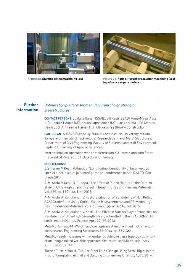
Kesla Oyj have executed a significant machine tool investment and got itup and running in order to increase manufacturing productivity and ca-pacity for high strength steel booms of the cranes. Kesla Oyj have got op-timized and standardized manufacturing parameters of milling, drillingand boring with HSS material. The level of automation and productivitywas increased by developing clamping systems that enables externalset up while machine is running.
Katsa Oy has increased their production efficiency by utilizing differentdigital manufacturing management processes. One main object was tominimize slow grinding operations and even replaced it by machining.Thus, delivery time and costs could be decreased considerably. Machineinvestment and process parameters for hard machining were definedby exploiting Six sigma (DMAIC-software) with DOE (design of experi-ments). Experiments were analysed by Minitab optimising tool and theresult was a new efficient production method for desired component.
39
Optimization platform for manufacturing of high strength steel structures
CONTACT PERSONS: Jukka Siltanen (SSAB), Vili Kesti (SSAB), Anna-Maija Arola(UO), Jaakko Haapio (UO), Kauko Lappalainen (UO), Jari Larkiola (UO), MarkkuHeinisuo (TUT), Teemu Tiainen (TUT), Ilkka Sorsa (Ruukki Construction)
PARTICIPANTS: SSAB Europe Oy, Ruukki Construction, University of Oulu,Tampere University of Technology: Research Centre of Metal Structures,Department of Civil Engineering, Faculty of Business and built Environment,Lapland University of Applied Sciences,
International co-operation was completed with KU Leuven and with Peterthe Great St.Petersburg Polytechnic University.
PUBLICATIONS:J. Siltanen, V. Kesti, R.Ruoppa, “Longitudinal bendability of laser welded special steel in a butt joint configuration”, conference paper, ICALEO, SanDiego, 2014.
A-M. Arola, V. Kesti, R. Ruoppa, "The Effect of Punch Radius on the Deform -ation of Ultra-High Strength Steel in Bending", Key Engineering Materials, Vol. 639, pp. 139–146, Mar. 2015.
A-M. Arola, A. Kaijalainen, V. Kesti, "Evaluation of Bendability of Hot-RolledS960 Grade Steel Using Optical Strain Measurements and FE-Modelling",Key Engineering Materials, Vols. 651–653, pp. 610–616, Jul. 2015.
A-M. Arola, A. Kaijalainen, V. Kesti, “The Effect of Surface Layer Properties onBendability of Ultra-High Strength Steel”, submitted to the ESAFORM2016conference in Nantes, France, April 27–29, 2016.
Mela K., Heinisuo M., Weight and cost optimization of welded high strengthsteel beams, Engineering Structures 79, 2014, pp. 354–364 .
Mela K., Resolving issues with member buckling in truss topology optimiz -ation using a mixed variable approach, Structural and Multidisciplinary Optimization, 2014.
Tiainen T., Heinisuo M., Tubular Steel Truss Design Using Semi-Rigid Joints,Proc. of Computing in Civil and Building Engineering. Orlando, ASCE 2014.
Figure 3a. Starting of the machining test Figure 3b. Four different areas after machining (test-ing of process parameters)
Further information

40
Tiainen T., Mela K., Jokinen T., Heinisuo M., Optimization of high strengthsteel tubular trusses, Proc of Eurosteel 2014, September 10–12, 2014,Naples, Italy.
Mela K., Heinisuo M., Economical utilization of high strength steel in weldedslim floor box beams, Proc of Eurosteel 2014, September 10–12, 2014,Naples, Italy.
Heinisuo M., Mela K., Tiainen T., Jokinen T., Baczkiewicz J., Rotational stiff-ness of welded tubular Y-joints, Elsevier, Proceedia Engineering (2015).
Havula J., Myllymäki H., Sorsa I., Haapio J., Heinisuo M., Experimental re-search of welded tubular HSS T-joints, welding times and moment resist-ances, IIW International Conference, High-Strength Materials – Challengesand Applications, 2–3 July 2015, Helsinki, Finland, 2015.
Diez Albero, J.A., Tiainen, T., Mela, K., Heinisuo, M. Structural analysis of tubu-lar truss in fire, Tubular Structures – Proceedings of the 15th InternationalSymposium on Tubular Structures, ISTS 2015, pp. 181–187.
Heinisuo M., Haakana Ä., Buckling of members of welded tubular truss, Pro-ceedings of The 13th Nordic Steel Construction Conference (NSCC-2015).Markku Heinisuo & Jari Mäkinen (Eds.), 23–25 September 2015, Tampere,Finland, 2015.
Kukkonen J., Heinisuo M., Comparison of relative volumes of different typeof welds, Proceedings of The 13th Nordic Steel Construction Conference(NSCC-2015) Markku Heinisuo & Jari Mäkinen (Eds.), 23–25 September2015, Tampere, Finland, 2015.
Tiainen T., Heinisuo M., Structural analysis models of steel trusses, Proceed-ings of The 13th Nordic Steel Construction Conference (NSCC-2015) MarkkuHeinisuo & Jari Mäkinen (Eds.), 23–25 September 2015, Tampere, Finland,2015.
Tiainen T., Heinisuo M., Definition of shear force for chord shear resistancecheck of welded tubular truss K-joint with gap. Proceedings of the XIIFinnish Mechanics Days, R. Kouhia, J- Mäkinen, S. Pajunen and T. Saksala(Eds.), Tampere, 2015.
Mela K., Alinikula M., Tiainen T., Heinisuo M., Sorsa I., Suunnittelutyökaluputkiristikoiden mitoitukseen ja optimointiin. Proceedings of the XII FinnishMechanics Days, R. Kouhia, J- Mäkinen, S. Pajunen and T. Saksala (Eds.),Tampere, 2015. (in Finnish).
Marsel Garifullin, Jolanta Baczkiewicz, Timo Jokinen, Teemu Tiainen, KristoMela, Markku Heinisuo. Surrogate model for rotational stiffness of weldedtubular Y-joints. The Tenth Annual Scientific Conference and Metnet Semi-nar Budapest, Hungary, on 13–14 October 2015.
Heinisuo M., Integration of design and manufacturing, presentation inFIMECC MANU Annual Seminar, Oulu, 17.11.2015.
Mela K., Design optimization on steel structures, presentation in FIMECCMANU Annual Seminar, Oulu, 18.11.2015.
Mela K., Korkealujuusteräs putkiristikoissa. Esitelmä: Teräsrakennepäivä2015. 25.11.2015.
Mela K., Optimization of HSS structures. METNET Workshop 8–9.2.2016. TUT,Tampere.

41
Tiainen T., MILP in steel frame optimization. METNET Workshop 8–9.2.2016.TUT, Tampere.
Garifullin M., Effect of weld size to the initial rotation stiffness of welded tubular joints. METNET Workshop 8–9.2.2016. TUT, Tampere.
Heinisuo M., Garifullin M., Baczkiewicz J., Jokinen T., Tiainen T., Mela K.. Surrogate models for moment resistance and initial rotational stiffness ofwelded tubular Y-joints. International Workshop on Connections in SteelStructures 2016,CONNECTIONS VIII, May 24–26, 2016, Hilton Boston BackBay Hotel, Boston, Massachusetts, USA.
Heinisuo M. Mela K., Tiainen T., Jokinen T., Cost Optimization of High StrengthSteel Structures. The 16th International Conference on Computing in Civiland Building Engineering. ICCCBE2016. July 6–8, 2016, Osaka, Japan.
Tiainen T., Mela K., Jokinen T., Heinisuo M., High strength steel in tubulartrusses. High Strength Steel Structures Themed Issue in ICE Publishing. ICEPublishing is a division of Thomas Telford Ltd, a wholly-owned subsidiary ofthe Institution of Civil Engineers. (in progress)
Van Mellaert R., Lombaert G., Schevenels M., Tiainen T., Mela K., Heinisuo M.,Global Discrete Size Optimization of Frame Structures. (in progress)
Tiainen T., Mela K., Jokinen T., Heinisuo M., Economical design of highstrength steel trusses using multi-criteria topology optimization, IABSE2016, Stockholm.
Garifullin M., Jokinen T., Tiainen T., Mela K., Heinisuo M., Chord stress func-tion for rotational stiffness of HSS square hollow section welded Y joints. (inprogress)
Machine tool energy efficiency and hard machining
CONTACT PERSONS:
Paavo Hopponen (Kesla), Jouko Kiviö (TUT), Sami Niemeläinen (Katsa)
PARTICIPANTS: Kesla, Katsa, TUT
PUBLICATIONS:
K. Ikkala, M. Lanz, J. Kiviö, and E. Coatanéa, “Energy efficiency evaluationmethod for machine tools,” in Flexible Automation and Intelligent Manufac-turing, FAIM2015, 2015, pp. 58–65.
K. Ikkala, J. Kiviö, H. Mokhtarian, M. Vainionpää and E. Coatanéa, "Characteri-zation of the cutting parameters in comparison to the machine tool inputpower", in Flexible Automation and Intelligent Manufacturing, FAIM2016, accepted.
Master's Thesis: Iria Villanueva Lire, Madrid TU, 2014 (in Spanish, extendedabstract in English). Manufacturing Process Management with Digital Manufacturing Tools.
Candidate's thesis: Mikko Merikoski, Machining of hardened steels with geometrically defined cutting edge (in Finnish: Karkaistujen terästen työstöterällä lastuavilla menetelmillä), Tampereen teknillinen yliopisto 2014. Published in MANU portal.

42
FINAL REPORT 2/2016
PROJECT NAME
PROMAGNET P3Jouni Lehtinen/MacGregor Finland Oy
Kimmo Leikko/Metso Minerals OyKari Hentunen/Piikkio Works Oy
Janne Kousa/Raute OyjMika Reinilä/ATR Soft Oy
Leo Torvikoski/Eurostep OyMarkus Mäkelä/Wapice Oy
Jorma Papinniemi/LUTAntti Pulkkinen/TUT
Jussi Liikkanen/TUASSimo-Pekka Leino/VTT
Productivity in the value chain depends on the efficiency of opera-tions and the effectivity of the results of the operations as a whole.Not only the efficiency but especially the effectivity of a production
network calls for high quality, up-to-date product knowledge, informationand data. For example, the effectivity of engineering is affected by thequality of product knowledge, information and data. The availability ofup-to-date information on product configuration is a necessity in down-stream production activities, such as procurement, part manufacturing,assembly, etc. Finally, the many services across lifecycle processes re-quire correct product data, such as a correct identifier for a spare-partnumber, and associated information, such as replacement instructions.All the lifecycle processes demand product information and also producelifecycle data and information that can serve as the basis for lifecycleknowledge for product engineering. The management of this process iscalled the closed loop PLM (Product Lifecycle Management) [Kiritsis etal. 2011]. In order to better utilize and reuse information for the extendedproduct throughout the lifecycle, well-defined information packages/modules and mechanisms are needed to support product developmentand to coordinate sales–engineering–manufacturing–delivery process-es, as well as for in-use and service processes.
The ProMaGNet project researched and developed commonprocesses and policies for networked product development and manu-facturing in the context of operations characterizing the Finnish manu-facturing industry. The project created new agile concepts, methods andsoftware for sharing product knowledge between stakeholders withinthe value chain in an appropriate form. All of these were developed in anetwork of project partners – the tight collaboration of the parties wouldnot have been possible without ProMaGNet. The characteristics of the
Summary of the project’s
motivation andachievements
Persistent Business Transformation with Product Knowledge and Lifecycle Management

43
Finnish manufacturing context will be presented later, but the results ofProMaGNet are first highlighted (see Table 1) and the impact of the re-sults reviewed. The remaining sections of the project report describe themeans and methods of research and development.
Table 1. The highlights of ProMaGNet results
RESULT IMPACT REFERENCE CHAPTER
Business oriented PLM implementationmodels
Enables companies to plan, deploy and benefit from a PLMroadmap for managing a business producing low volumeand high variety products more systematically.
Business impacts of project decrease lead-time even by20% for every repeated process is enabled by shared datamodules on the repeatability of projects and earlier prod-uct-related data.
Implementing PLM for Low Volume Manufacturing
Broad re-use ofproduct knowl-edge and designautomation
The systematic means of design automation become a com-pany-wide means of saving thousands of engineering hoursover a period of 0–3 years
Capturing and re-using Knowledge on High Variety Products
EnhancedChange Manage-ment (ECM+)
Change Manage-ment as definedin CMII standardwith releasedproducts
Proactive changemanagement in product development
Systematic change processes, review practices and digitalproduct models (ref. 3D+ & IVP) enable substantial savingsin time and costs by preventing material shortages and er-rors (15–25%) from progressing to production and procure-ment. This will have a radical impact on engineering andproduction over a period of 1–5 years.
Updating and main -taining product knowledge through- out product life cycle
Expanded 3D(3D+) & Inter -mediary VirtualPrototyping (IVP)
Enable capturing and transforming product knowledgefrom all stakeholders, thus design and validation of prod-uct’s downstream properties and processes already in vir-tual stage. 3D+ and IVP models structure and conceptualizevalue creation mechanisms and preconditions for PLM anddigitalization of manufacture. Radical impact in engineeringand production over a period of 1–5 years.
Utilizing state-of-the-art digital means for product representation anddocumentation
Concept of Location Inde-pendent Manu-facturing andSupply (LIMS)
LIMS, as a new business model will enable new ways ofmanaging factory plant & technology projects supported bynew PLM platform based solutions. Competitive advantagefor project and lifecycle business can generate substantialgrowth and profit in the future, when implemented.
Sharing and Usingproduct knowledge in manufacturing Networks
New generationsoftware prod-ucts for PLM domain pub-lished.
Companies can start productive PLM utilization in a shortertime, and can have better user experience with complexPLM information over the end-to-end PLM business pro -cess. Collaboration between companies can be enabled inall lifecycle phases of project, product or service. Strength-ening the position in domestic and opening doors in inter-national PLM software markets. The PLM market is forecastto grow from US$ 40 billion in 2014 to US$ 75 billion in2022.
Capturing and re-using Knowledge on High Variety Products,
Sharing and Usingproduct knowledge in manufacturing Networks
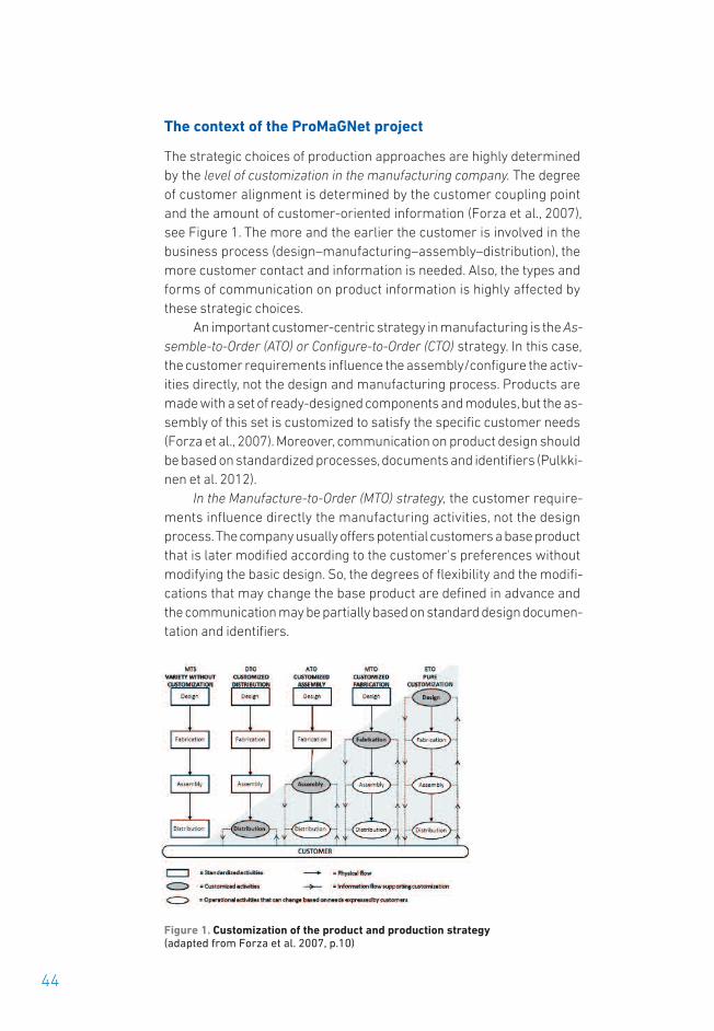
44
The context of the ProMaGNet project
The strategic choices of production approaches are highly determinedby the level of customization in the manufacturing company. The degreeof customer alignment is determined by the customer coupling pointand the amount of customer-oriented information (Forza et al., 2007),see Figure 1. The more and the earlier the customer is involved in thebusiness process (design–manufacturing–assembly–distribution), themore customer contact and information is needed. Also, the types andforms of communication on product information is highly affected bythese strategic choices.
An important customer-centric strategy in manufacturing is the As-semble-to-Order (ATO) or Configure-to-Order (CTO) strategy. In this case,the customer requirements influence the assembly/configure the activ-ities directly, not the design and manufacturing process. Products aremade with a set of ready-designed components and modules, but the as-sembly of this set is customized to satisfy the specific customer needs(Forza et al., 2007). Moreover, communication on product design shouldbe based on standardized processes, documents and identifiers (Pulkki-nen et al. 2012).
In the Manufacture-to-Order (MTO) strategy, the customer require-ments influence directly the manufacturing activities, not the designprocess. The company usually offers potential customers a base productthat is later modified according to the customer's preferences withoutmodifying the basic design. So, the degrees of flexibility and the modifi-cations that may change the base product are defined in advance andthe communication may be partially based on standard design documen-tation and identifiers.
Figure 1. Customization of the product and production strategy (adapted from Forza et al. 2007, p.10)

45
In pure customization, the most intensive customer orientation isachieved by the Engineer-to-Order (ETO) strategy and products. ETO orproject-based manufacturing is suitable for unique products that havesimilar features, and where the production is based on receiving a cus-tomer order and developing a technical specification accordingly (Silven-toinen et al., 2014).
Project-based manufacturing companies are striving for innovationacceleration, lean supply and product processes throughout the lifecycle.Product requirements and available information are key factors for busi-ness success and competitive advantage. However, requirements arealways on the move. Customers often change their mind; market driverschange; authorities keep adding new constraints relating to environmen-tal or safety concerns; and sometimes the project encounters difficultiesthat require a revision of the initial targets. There are several challengesin reusing requirements information, e.g. tracking and tracing of require-ments in product-related structures, processes and applications (Papin -niemi et al. 2013).
The goal of ProMaGNet
The goal of the project can be summarized as a generic ProMagNet mod-el, which adapts PLM for the typical context of the Finnish ManufacturingIndustry. The ProMaGNet model manifested as Product Lifecycle Man-agement (PLM) capabilities that support the transformation of compa-nies. The transformation means the renewal of business operations fromthe consecutive engineered-to-order (ETO) projects to configure-to-or-der (CTO) manufacturing approach with a supporting set of well-defined,captured and re-used product knowledge, information and data (Pulkki-nen 2007). The case companies were either taking the first steps towardssystemic customization or were more advanced companies regardingthe matter. The first ones defined and implemented the most essentialcapabilities and the latter ones enhanced the creation, capturing, man-agement and use of product definition throughout the product lifecycle.The project focused on the capabilities of capturing the product-relatedknowledge, information and data in a single source, where these assetscan be re-used throughout the product lifecycle (see Figure 2).
It can be summarized that previously many companies have beeninvolved with development projects that aim for demonstrations and pro-totypes of a modular product family definition. However, without strategicinvestment in the organization capabilities as well as systematicprocesses and tools, the demonstrations do not ensure the transforma-tion. This was the situation in some of the case companies that rolled outthe first PLM system implementations during the project. Also, thebreadth of the market offering may be very limited with a demonstration

or proof-of-concept project. The ProMaGNet project consisted of indus-trial cases on PLM implementation, product design systemization, inte-grating 3D product models into review practices and product configura-tion, the analysis and capturing of product portfolio as configurationknowledge in sales and engineering configuration systems, etc. The ex-periences and capabilities developed in joint industrial case-projects andresearch tasks are collected in the themes of PLM capabilities in latersections.
Figure 2. Developing PLM capabilities for leveraging business needs: the trans-formation of manufacturing and new businesses
The participating manufacturing companies were in different phases ofthe PLM implementation process. Metso Minerals had a sound basis oftraditional product data management, and they were expanding the PLMframework towards new processes and tools. MacGregor was boostingtheir product delivery projects by moving from document-based productdata management towards one that was item-based, establishing prod-uct platforms and building engineering design automation on many lev-els. Raute was undergoing a transformation from one-off type projectstowards modular product platforms and product lifecycle management,by defining a business oriented PLM model with the intention to supportbusiness goals. The company Piikkio Works was building PLM founda-tions for design automation and increasing integration between ERP-PDM-CAD systems. The software providers and PLM facilitators, Euro -step, ATR Soft and Wapice co-operated with the manufacturing compa-nies and developed new generation solutions for Finnish industry andglobal markets.
46

47
How do processes and organizations enable the achievement ofstrategic goals besides PLM software and technology?
Business models, value chains and networks contain many processesdriven by people who belong to various organizational and networkedstructures. Making these processes more efficient and effective, for in-stance by removing waste like unnecessary re-working is one approachto achieving strategic business goals. New business models may evenrequire totally new processes and organizational structures. Thesetransformations can be supported by improved utilization of knowledgein peoples’ minds, and the development and implementation of PLM.These kinds of transformations were present in many of the ProMaGNetcompanies and continued after the project.
Manufacturing and supply of complex and project-specific productsis typically conducted within a flexible network of various internal andexternal stakeholders. These stakeholders need to access, create andinteract with up-to-date product knowledge. Concurrent and real-timeproduct knowledge is essential for efficient manufacturing processes.However, the sharing of product knowledge has challenges and alsorisks. Product knowledge is often available only in one form (e.g. CADmodels), which hinders its use among different internal and externalfunctions (manufacture, assembly, logistics, after sales, service). In ad-dition, product knowledge may not be up to date and available as timegoes by. On the other hand, sharing of product knowledge carries the riskof core competence leakage to competitors.
In the ProMaGNet project a common objective was to enhance theholistic product-life approach over the traditional functional silos of com-panies and departments. Besides development of the traditional on-wards information flow from engineering design towards productionand later lifecycle phases, also the feedback flow backwards to engineer-ing design and product management was a special focus. Companiescontinue to develop these capabilities beyond the project time limitations.
Implementing PLM for low volume manufacturing
Industrial companies in the ProMaGNet project are sharing the sametype of operation strategy, based on customer-orientation with a low-vol-ume & high-variety product base. Companies have set out to improvetheir competitiveness, each from their own baseline for defining the de-gree of customization and modularization. In order to describe the rela-tion of volume and variety, the High Mix/Variation, may cover for examplehundreds or thousands of active part numbers, a few with active fore-casted volume. A Low Volume lot size is dependent on the customer (usu-ally a small order size).

As it is assumed that low-volume & high-variety products are noteasy to modularize, this means these kinds of products are seldom oronly partly configurable, as they lack modular structures in the sense ofHarlou’s (2006) standard designs. In project-based manufacturing thereis, however, a need to build up the reusability of product design, compo-nents, and modulesutilizing a configure-to-order (CTO) -based modularity(product modularity /platform base).
Figure 3. Modularity at the project level for gaining repeatability
However, at higher level, supply/delivery projects could be modularizedutilizing product platforms and process modularity (Abdelkafi, 2006).The question is: what are the factors differentiating ‘project-based prod-ucts’ such that the earlier made designs cannot be reused? A typical an-swer is that the designs are not standardized modules or they are noteasily available. In project-based (ETO) manufacturing repeatability atproject level can be achieved through guidelines for process modularity,workflow commonality and shared data & information objects.
Repeatability in a company context means reuse of some specificprocess part of an industrial plant and its machinery.
Project business concepts based on modularity could allow a timedecrease of even 20 percent for every repeated process. The modularmanufacturing/construction concept could thus bring significant value-added to the normal stick built project concept.
48

49
Deriving the product lifecycle concept and roadmap for PLM
Developing modular product structures, product platforms and config-urable product families is not enough for successful product customiza-tion. According to Harlou (2006), the definition of standard design in-cludes not only the intention of reuse and the definition of standard de-sign itself, but also the way and the means of documenting the standarddesigns for re-use. This involves defining configuration processes andsetting up support for product configuration. PLM systems and process-es are vital in enabling the documentation and the means of reuse. Fora company that is taking steps towards systemic customization and CTO,the definition of the PLM strategy, processes and structures are neces-sities.
During the project Raute defined a PLM strategy based on the business-oriented PLM concept for a Finnish project-oriented, low-volume andhigh variety manufacturing company. The impact of this is a higherawareness of PLM issues. Presumably, the awareness will enhance thetransition to systemic customization and implementation of PLM as well
“Piikkio Works has gained results especially in the development of as-sembly and logistical flow processes. Changes are seen in daily man-agement and measuring targets in different levels of the organization.One big strategic achievement has been the reduction of material andfinished product stock. Piikkio Works Oy has also improved designprocess efficiency and design quality with own CAD environment devel-opment as well as by increasing integration between ERP - PDM - CADsystems.”
Kari Hentunen, R&D Manager, Piikkio Works Oy
Companyimpact
Companyimpact “These discoveries we will use to take the next steps and transform our
organization toward creating value from product life cycle data, workingon topics such as defining tangible and intangible products, applyingnew PLM functionality and moving gradually from the ETO to CTO busi-ness model.”
Elli Leino, Engineering Systems Specialist, Raute Oyj

as prevent the many errors related to the learning-by-doing approachthat may well be the dominant strategy in software implementation. Dur-ing the project Raute recognized processes and structures in the organ-ization that are not supporting life cycle business optimally, and on theother hand we developed new processes that cannot work without com-plete and accurate product data. How Raute will succeed in implement-ing PLM will be a critical strategic factor in sustaining the company'scompetitive advantage.
Needless to say, PLM is much more than a software issue but alsoa matter of processes and organizations (Ameri & Dutta 2005). However,the limited time span of the project prevents an objective study on theimpact of PLM in the case. Thus, the perception of the company is the val-idation of the research:
During the ProMaGNet project MacGregor and Piikkio Works also de-signed for the utilization of PLM systems to achieve improved productdata reuse and management. They also studied the relation of PLM atthe strategic, organization and process levels, when the purpose of thePLM systems was tightly related to the modularization and parametriza-tion strategies of the companies and also to the enhanced sharing ofproduct information between the engineering, manufacturing, procure-ment, and logistic organizations.
Capturing and reusing knowledge on high variety products
One theme within the ProMagNet project related to the creation of prod-uct data and the capturing of product-related knowledge. The main hy-pothesis in the theme was that the adoption of the integrated product da-ta model improves the quality of information and enhances the opera-tions of a networked project delivery.
50
Companyimpact "As a result of this project, Raute's Product Lifecycle concept has been
re-written to include new approaches for Service offerings, Product life-cycle practices and Digital services. This all will have a major impact onthe future development of new products and offering portfolio."
Janne Kousa, Engineering Manager, Raute Oyj

51
MacGregor escalated the use of the engineering configuration conceptdeveloped in the previous FIMECC program Innovations and Networks(2009–2014). The automatized 3D-model generation was being utilizedalso for different types of products than in the original case. The use ofthe parametric CAD model was based on the skeleton model, which wasfurther enriched by configuration software and optimization algorithms.For example, the productivity of the tasks of other stages of engineering,such as manufacturing documentation, were being automatically de-tailed with the use of computer-aided engineering (CAE) software, suchas CUSTOMTOOLS by ATR Soft. For example, the material lists were generated automatically from the 3D model and further used for down-stream documentation, which will save tens of engineering hours in eachproject and elevate the quality of the documentation. The company alsoinvested in others system, such as PDM/PLM and ERP and studied thepotential related to the sales configuration as well as to the configurationof operation manuals. Depending on the future strategy of the company,these pieces of software will be implemented after the ProMaGNet project.
Figure 4. Generation of the K-Drawings (the result of a collaboration betweenMacGregor and ATR Soft)
Companyimpact “With the systematic development and implementation of PLM capabil-
ities MacGregor has significantly improved the management of para-metric and configurable product architectures. This will improve the ef-ficiency and quality of product development by enabling concurrent en-gineering practices, change management and knowledge sharing.”
Jouni Lehtinen, R&D Director, MacGregor Finland Oy

Raute defined and classified their product base of hundreds of differentproject types into three main product-service categories. Also, a compa-rable set of intangible, but standardized service products were being de-fined for future implementation. However, the work related to the docu-mentation and utilization of the reusable asset is unfinished, althoughthe concepts are being laid out. The company started to understand PLMas a means of collecting lifecycle knowledge. This may well lead to anenhanced development of lifecycle business offerings, e.g. by utilizingthe Internet of Things, Big Data, Simulator Aided Development. Thus, therealization of a closed-loop PLM is potentially beneficial to the businessin the near future.
Wapice developed further its Summium configurator and imple-mented 3D functionality in the sales configurator. It is now possible to in-tegrate the configurator more closely to PLM systems and engineeringin general. Also, the 3D constraints and rules can be defined in order tobetter meet the requirements of the CTO companies.
In summary, the technology and its novel utilization related to productconfiguration were being developed in and had begun to deliver duringthe ProMaGNet project. Furthermore, the singular cases and softwaresystems were being integrated so as to create continued processes andinformation sharing. Also, the concepts related to lifecycle informationpractices for installed equipment base management as well as the cre-ating of new (digital) service business were being outlined. The impactrelated to these is comparable to the utilization. For example, the payback of an investment in product configuration is achievable in monthsthrough larger market potential. However, the strategic investments inPLM as a whole might not have been taken (at least at such a pace) with-out the ProMaGNet project. These investments have a larger impact asthey will integrate product configuration and product knowledge man-agement with PLM.
52
Companyimpact “Wapice has advanced the customer-oriented approach to product con-
figuration by developing 3D-based configuration where 3D-models al-ready existing in PLM systems can be utilized. As a result, the informa-tion sharing between non-technical and technical product requirementsin customer-sales-production spheres can be significantly streamlinedand enhanced.”
Markus Mäkelä, Business Development Director, Wapice Oy

53
Updating and maintaining product knowledge throughout product lifecycle
One theme focused on the knowledge engineering methods and productstructures, for example, change management and modularity. Engineer-ing Change Management (ECM) may consume 30–50%, and sometimesup to 70% of production capacity. Typically, the complexity of change man-agement is due to the great number of the involved internal/external ac-tors (with their own ambitions), constantly changing requirements, tightschedules, and technically challenging integral solutions. Geographicallyseparated production increases the challenges for the ECM even more,since the location of manufacturing sites, transportation costs, and re-lated services are an essential part and source of engineering knowl-edge.
The maturity of ECM was characterized as evolving within three di-mensions: the content of the ECM process and its implementation; thecommunication and coordination of changes; and the content of thechange, i.e. how changes are “modularized” as change packages. Thematurity model was used to characterize the benchmarked companies.The model can support the companies in developing their change man-agement capabilities (Pulkkinen et al. 2015).
The ProMaGNet project produced an Enhanced Change Manage-ment (ECM+) approach that includes a set of means and methods for theproduct development project and a holistic approach to enterprisechange management for the changes within production. With its broaderstakeholder involvement and processes orientation the method stressesthe packaging of changes into releases or updates, as found in otherfields (such as in ICT & car manufacturing).
Companyimpact “Implementation of the CMII style of change management has enabled
a more systematic approach to engineering changes. The change re-lease system makes production planning and purchasing more pre-dictable and therefore more efficient. Benefits can be seen also at ven-dors because the change packages are easier to handle than a pack ofseparate changes.”
‘
Kimmo Leikko, Development Manager, Metso Mining and Construction

A first part of ECM+ is the adoption of ECM as defined in configurationmanagement II (CM II) in low volume manufacturing, which took place inMetso Minerals. This step is remarkable, since CMII can be regarded asa comparable product management method to Lean methodology in pro-duction. Configuration management is a standardized methodology forelectronic (ANSI/EIA-649) and military (MIL-STD-31000A) industries, butthe utilization of CM in the context of project businesses has been a chal-lenge. It has for some time been acknowledged as an important meansfor improving engineering change management (Inkinen 2008), but theutilization of CM II principles requires not only PLM system capabilitiesbut also trained personnel and an awareness in the organizations. Theawareness and training proved to be crucial in the case of Metso Miningand Construction (MAC), when the change management procedureswere being implemented. In fact, no essential changes were being madeon the PLM system used, but rather in the organization and mindset with-in engineering. We believe that the new way of managing changes shouldbe disseminated and extended to supply networks, in order to achieveadditional impact and productivity leap throughout the suppliers.
Figure 5. The methods for enhancing engineering collaboration and changemanagement in product development
According to our estimations the second part of the ECM+ frameworkrepresented in Figure 5 requires an investment in ECM that is compara-ble to one fifth of the product development project. The part of the ap-proach includes processes, methods and digital tools, indicators andmetrics for the execution and management of the product developmentproject. As can be seen from Figure 6, the approach is highly connectedto the state of the art digital means and concepts for representing prod-uct content (presented in the next section).
54

55
We have estimated the significant benefit that can be attained with thefirst few delivered products, i.e. already within the production of the 0-series. The frontloading of product development is economical when anexecuted change can be ten times cheaper to procurement before therelease than after the release. When the number of these kinds ofchanges can be counted in hundreds, the savings are substantial. Theapproach leads to improved engineering quality as well as a time andcost reduction in production ramp-up.
In the companies there has been a lot of hidden potential related to en-gineering and enterprise change management that could be harnessedwith the aid of public funding. Without it, the development leap that hasbeen taken would probably have not been taken due to everyday dutiesand a lack of short-term profit. The enhanced awareness, knowledgeand the utilization of state-of-the-art methods requires a strategic in-vestment from the companies’ point of view.
Utilizing state-of-the-art digital methods for product representation and documentation
One theme within the ProMagNet project was knowledge intensiveprocesses (such as the sharing, utilization and modification of productknowledge) in global networks with external and internal actors. Themain hypothesis of this research theme is the acquisition of substantialdirect and indirect savings through the utilization of the integratedprocesses and the establishment of new value-creating processes with-in the product life. For instance, the assembly, maintenance service andafter-sales are processes that benefit to/from integrated and system-ized product knowledge as well as engineering tools and methods thatutilize the knowledge.
Companyimpact “New product development indicators have made it possible to predict
the potential of early stage production development benefits. The ben-efits can be up to 10-times bigger than the invested cost in the first 2years of a new product life cycle.”
Kimmo Leikko, Development Manager, Metso Mining and Construction

Boosting new product development projects /Case Metso Mining and Construction
In the case study of Metso Mining and Construction (MAC), virtual proto-typing in the integrated product development enabled knowledge shar-ing and improved utilization of 3D-based visualizations between engi-neering design and development, as well as with other product stake-holders.
During the ProMaGNet project a comprehensive analysis of currentnew product development practices was conducted. As a neutral party,researchers interviewed some 20 people from several organizationallevels and from nine internal functions (product management, projectmanagement, engineering design, product development/productization,procurement, sourcing, production, quality management, and after-mar-ket) and representatives of two mechanical supplier companies. The pur-pose of the analysis was to assess the current strengths and best prac-tices as well as the main development targets and areas where digitali-zation could create most value within the new product development andthe time-to-market and time-to-profit goals. Increased utilization of 3Dmodels and improved product design review procedures were recog-nized as a potential means for reaching those business targets. Thesehave a positive impact on collaboration, communication, organisationalknowledge creation, decision-making and overall management. In-creased utilization of digital product models and design reviews enablea frontloading of the NPD process, thus decreasing the need for physicalprototypes and costly engineering changes.
Based on the NPD case study of Metso MAC, a 3D+ framework modelwas created. As part of the 3D+ model, Intermediary Virtual Prototyping(IVP) is a new concept (Leino, 2015) resulting from this research. It un-derscores the many layers and dimensions involved, from the technicaladvantages of 3D and virtual environments to the expanded mediatingobject of a humanistic product development activity system. The 3D+model includes new generation product processes, organizational de-sign, methods and tools such as virtual prototyping and virtual environ-ments, together with information flow and a richly expanded product da-ta model for the IT system support. The 3D+ model defines how virtualprototyping methods support and benefit various business processes,such as requirements and engineering change management, design forlifecycle, assembly and service support, stakeholder (internal functionsand disciplines, and external customers and suppliers) involvement andcommunication within integrated product development and concurrentengineering.
3D+ contributes to the product lifecycle management (PLM) para-digm by enabling better design and validating the product’s downstream
56

57
properties and processes – such as production and maintenance – already in the virtual product phase, and sometimes already in the prod-uct concept phase, before the big decisions have been made. The scien-tifically proven benefits and impacts (Leino, Koivisto, & Riitahuhta, 2013),(Aromaa, Leino, & Viitaniemi, 2013), (Leino, 2015) of the applications ofthe 3D+ reference model are related, in addition to the 3D technology, togaining added value for the product process, people and organization aswell in business management and decision-making. From the organiza-tional design and management perspective, IVP is a medium for bettercontext-based communication and collaboration between manufacture,assembly, design and other functions, including the ability to reveal ab-stract information and tacit knowledge. The improved user interface withthe product model enables various stakeholders, from assembly work-ers to human factors experts, designers, and managers, to understandthe model in the same way. All product stakeholders benefit, becausedesigners learn about the required external properties and their rela-tions to design properties. Virtual prototyping and virtual environmentswere applied mainly in design review meetings where participants frommany functions and organization levels were involved. This participatorydesign approach improved the systematic and holistic view from the per-spectives of many stakeholders during a product life-cycle. 3D+ enablesthe receipt of feedback from production and other product downstreamlife-cycle stages by the design team already before the physical proto-types are produced. Therefore, it enables the generation of engineeringdesign changes in the early virtual product phase and a decrease in thenumber of costly changes in the detailed design phase and with physicalprototypes and production. Thus, it was concluded that engineeringchange management (ECM) was one of the main drivers of developing3D+ in the case company. 3D+ enables catching at least the most criticaldesign flaws before creating the manufacturing documents and physicalprototypes. 3D+ also provides for analyzing the engineering change re-quests, change impacts, and validation of engineering change decisions.3D+ can be utilized in manufacturer’s instructions and manuals, and inthe future also in Manufacturing Execution Systems (MES).
Configurable products and variant production require flexibility,which leads to manual, work-intensive assembly tasks and productionstyles. IVP is particularly beneficial in manual, work-intensive variantproduction, where human skills and knowledge contribute to the flexi-bility of the production system. This can be justified by improved com-munication and understanding between people, and collaboration withinorganizations, and thus earlier feedback from the downstream life-cycle.3D+ enables the testing and investigating of several product configura-tions and variants compared to just one physical prototype. The advan-

tages of 3D+ contribute to the productivity and Lean paradigm of newproduct development through saved time and resources, through a decreased number of physical prototypes and non-value adding worksuch as unnecessary re-work and engineering changes. 3D+ enables in-creased understanding of the product for all stakeholders. It enables get-ting at the real root problems faster, thus giving earlier and holistic prob-lem solving.
ProMaGNet increased understanding of the intermediary virtual proto-typing as a concept, its potential capabilities and benefits, as well as therequired pre-conditions for its implementation and utilization.
When the focus of virtual prototyping was expanded from the firsttechnology demonstrations to real, new product development projects,it was understood that it will have a wide impact on processes, organi-zations, and technology infrastructure, like product data management.Small gains can be achieved locally through incremental steps, but themajor benefits can be achieved only when the product life and businessis taken as a whole. This can be considered as a systemic and revolution-ary paradigm change. Intermediary Virtual prototyping (IVP) and 3D+must not be considered only as a piece of technology, but as a combina-tion of technology, methodology, processes, and infrastructure in relationto the technology, people and organizations, and management. The valuecannot be captured without a holistic view of 3D+. From the PLM perspec-tive the 3D+ model includes three main dimensions (Figure 6): 1) Lifecy-cles of product definitions and product individuals, 2) information flowand knowledge creation between product stakeholders, 3) product def-inition maturity, product structures and data management.
58
Companyimpact "The use of advanced 3D methods has led to better quality in manu-
facturing/planning and therefore shorter time to profit."
Lauri Jokinen, Development Engineer, Metso Mining and Construction

59
Figure 6. The role of 3D+ in product definition, life and related organizations
These dimensions can be discussed as process, organizational, and tech-nological implications for manufacturing companies:
• Process implications. Effective utilization and IVP value capture re-quires a paradigm change in new product development. Virtual proto-typing should be understood as a pivotal process within NPD and PLM.This means that the virtual product process phase should not focus onproducing 3D models and manufacturing documents for the physicalproduct process, but it should include the whole product life-cycle. TheNPD project and process should be frontloaded so that, for instance,assembly and maintainability analyses and improvements can be doneusing the virtual prototypes. The frontloading may increase the workand cost at the beginning of the project, but it may also decrease theengineering changes and the cost of physical prototypes in the physicalproduct process phase. The paradigm change also affects how the de-sign model maturity should evolve during the NPD project and process.The way of producing CAD models should better serve IVP.
• Organizational implications. It was concluded that one aspect in whichIVP creates value is through broad integration and involvement ofstakeholders in NPD. Therefore, it is important to recognize and involve

the stakeholders at the organizational group level, but also at the individual person level. Hence, it is suggested that NPD with IVP shouldbe organized in dynamic teams, where all the needed stakeholders areinvolved. On the individual person level, there should be new roles forimplementing, developing, and operating virtual prototyping. From thebusiness management viewpoint, it should be understood that IVPdoes not belong just to a single organizational function, business line,or department, but that it is proposed to be a holistic system and partof product life-cycle management.
• Technological implications.The effective utilization of virtual prototyp-ing requires bi-directional data and information flow between virtualenvironments (VE) and product data management (EDM/PDM) sys-tems. The interface between VE and EDM/PDM also requires a processof data conversion and simplification, which should be at least partlyautomated to be efficient. However, the product structure (hierarchy),as well as metadata such as item codes and version and revision in-formation, should be transferable bi-directionally.
In the case study, the possibility to make comments and give feed-back directly on the virtual prototype model was one of the most de-sirable capabilities of IVP. In EDM/PDM, which is the backbone of PLM,the product structure is normally the main framework that constitutesthe product information model. Therefore, VP and related data, infor-mation, and documents should be referenced with the product modelin order to contribute to knowledge management. A virtual prototypeas a baseline structure is proposed as the frame for explicit knowledgemanagement, linking the tacit knowledge from stakeholders to PLM.It is proposed to manage the documentation, feedback, requirements,notes, and engineering change requests, for instance, from virtual de-sign review meetings.
60
Companyimpact "The research on parallel structures and factory simulation (Tecno-
matix) has given us wider understanding on what implementing fully3D-based production planning would mean for our company from theperspective of work load, system infrastructure and visual communica-tions."
Lauri Jokinen, Development Engineer, Metso Mining and Construction

61
Another aspect of frontloading is the use of multiple product views fordifferent stakeholders. The utilization of multiple views is a concept thatwas studied in the project by Kariniemi (2014). The concept has had sev-eral purposes, such as product variant management, systemization andconfiguration (Erens & Verhulst 1996, Harlou 2006), but in the project theintention was to study the benefits of utilizing multiple views and parallelstructures for integrated product and production engineering. The real-ization of the concepts was ensured with three case studies with newand operational software. Not only substantial benefits but also the re-quired investment and the capabilities of state of the art software werebeing recognized.
Sharing and using product knowledge in manufacturing networks
Product-related data is usually created with various design systems andwithin different stages of product lifecycles, which leads to fragmenta-tion. This has negative effect on the sharing and exploitation of data aswell as on efficient change management. Besides data and knowledgeof the physical product, all the knowledge about the manufacturing, main-tenance, use, services and recycling should be ‘modularized’, if possible,and linked to the PDM or PLM system. This project produced solutionsfor the integration of fragmented product and lifecycle data.
Eurostep, Wapice and ATR Soft as PLM facilitators developed newgeneration solutions for managing effective product data managementand sharing in a networked business environment.
Creating capability for Location Independent Manufacturing and Supply (LIMS)
As a part of the ProMaGNet project, Raute has investigated the LIMS con-cept (Location Independent Manufacturing and Supply). In the future, thetraditional ERP-based management system could be a part of the wholebusiness management system. The role of LIMS was considered espe-cially in constantly changing markets and temporary manufacturingsites or geographically separated production. The aim was to significantlyreduce the design time and bridge the gap between product developmentand manufacturing. New knowledge and practices were produced con-cerning how the possible modularization of a LIMS project relates to themanufacturing and outsourcing strategies and customization possibili-ties. The ProMaGNet project provides novel insights into the role of ’pro-ject modularity’ when balancing between customer needs, delivery timeand expenses. In practice, this means versatile project variants for cus-tomers and better productivity for manufacturing companies simultane-

ously. These approaches serve for instance the business goals andprocesses of Mobile Factory (Piikkiö Works) and Location IndependentManufacturing (Raute).
Creating solutions for the new generation networked PLM platform
Collaboration in manufacturing networks requires new kinds of ap-proaches and solutions. One aspect is the sharing of product knowledgebetween different manufacturing parties in a global supply chain (e.g.standards, raw materials). Another aspect is the integration and sharingof product knowledge between different engineering disciplines andmanufacturing (e.g. feedback).
62
Companyimpact "As a part of this project, Raute has investigated the LIMS concept (Lo-
cation Independent Manufacturing and Supply). In the future, the tradi-tional ERP-based management system is only a part of the whole busi-ness management system. When we are working on a global businessenvironment where the focus for executing the projects and services isnot based on fixed manufacturing locations, but is based on customer'slocations and local infrastructure, we need new know-how and tools (lo-cal rules, 4PL logistics, Cloud-ERP, etc.). A concrete base for this is a realtime PLM-system as well as progressive usage of related IT-systems.The added-value of what is achievable through this new concept needsto be measured. Part of the project is also to renew KPI-system for busi-ness units."
Antti Aholainen, Purchase Manager, Raute Oyj
Companyimpact ”The ShareAspace Nova platform and InReach is the outcome of an in-
tense development project with reference guidance from some of ourkey customers. The needs and requirements of Finnish industry areused as valuable input in the development work. The result is a newway for Eurostep and Partners to deliver Secure PLM Collaboration forJoint Ventures, Partner Collaboration and more. To users, InReachmeans solutions in a shorter time and with increased performance oneven larger data volumes. The key is application configuration basedon best practice templates.”
Leo Torvikoski, Managing Director, Eurostep Oy

63
Often the integration of different pieces of PLM software has been thestrength of consulting companies, which have been able to make inte-grations and support related migrations with the 1-of-a-kind, project-based approach. Each time, this has involved the time and effort of highlyqualified personnel. In ProMaGNet the paradigm was challenged by developing a more industrialized manner for the software integration.This approach may well enable the software companies to expand theirmarket presence to other countries, because the potential for re-use in-creases.
Utilizing a shared platform and best practice templates aim to boost man-ufacturing collaboration by consolidating product knowledge from alllifecycle phases (development, design, manufacturing, in-use) providingthe manufacturing stakeholders with quality data (i.e. ensuring the dataare available, up-to-date, accessible, consistent, correct, etc.), and in-creasing the reuse of product knowledge between stakeholders and life-cycle phases.
Instead of exchanging information, the focus is on innovative conceptsof sharing, both with internal and external stakeholders. The advantageof sharing is to both streamline integration and avoid unnecessary over-lapping of work, and therefore to boost the global supply chain.
Companyimpact
“The ATR Soft strategy is to develop more of our own products and dur-ing the DIMECC MANU project we have been able to significantly im-prove and facilitate this goal. The company has gained a lot of newinformation about the needs in different sized companies. This infor-mation has given many new product or service ideas. The companyhas been able to conduct numerous studies and demos to verify thatits current and planned solutions work correctly and efficiently. Thisinformation and knowledge will help ATR Soft to grow not only ourproduct and service portfolio but also the whole company revenue andthe number of employees.”
Mika Reinilä, CEO, ATR Soft Oy

CONTACT PERSONS:
Jouni Lehtinen ([email protected]) Kim mo Leikko ([email protected]) Kari Hentunen (kari.hentu [email protected])Janne Kousa ([email protected])Mika Reinilä ([email protected]), Leo Torvikoski ([email protected])Markus Mäkelä ([email protected])Jussi Liikkanen ([email protected]) Jorma Papinniemi* ([email protected]) Antti Pulkkinen* ([email protected]) Simo-Pekka Leino* ([email protected])
PARTICIPANTS:
ATR Soft OyEurostep OyLappeenranta University of TechnologyMacGregor Finland Oy Metso Minerals Oy Piikkio Works Oy Raute OyjTampere University of TechnologyTurku University of Applied Sciences VTT Technology Research Centre of FinlandWapice Oy
REFERENCES:
Kiritsis, D. (2011) Closed-loop PLM for intelligent products in the era of theInternet of things, Computer-Aided Design 43, 479–501.
Forza, C., Salvador, F. (2007) Product Information Management for MassCustomization, Palgrave Macmillan.
Pulkkinen, A., Martikainen, A., & Kuusela, J. (2012). A Framework of designfor procurement. In: K. Bernhard, H. Thomas, S. Klaus, & T. Klaus-Dieter (Editors), Proceedings of the 18th International Conference on Engineering,Technology and Innovation 2012, ICE 2012, 18–20 June 2012, Munich, Germany. 307–316.
Silventoinen, A., Denger, A., Lampela, H., Papinniemi, J. (2014) Challenges ofinformation reuse in customer-oriented engineering networks, Internation-al Journal of Information Management, 34, 720–732.
Papinniemi, J., Fritz, J., Lipiäinen, N., Denger, A., Hannola, L. (2013) Opportu-nities of modularity for reuse of requirements information in project basedmanufacturing, 22nd International Conference on Production Research inIguassu Falls, Brazil.
Pulkkinen 2007, Product Configuration in Projecting Company: The Meetingof Configurable Product Families and Sales-Delivery Process. Doctoral dis-sertation. Tampere University of Technology. Publication;712, 183 pp.
64
Further information
*) editors of the final report

65
PUBLICATIONS:
Huhtala M., 2014. PDM system functions and utilizations analysis to improvethe efficiency of sheet metal product design and manufacturing, Disserta-tion, Lappeenranta University of Technology. 158 p. (http://www.doria.fi/bitstream/handle/10024/97266/Merja%20Huhtala%20dissertation.pdf?sequence=2)
Leino, S-P., 2015. Reframing the value of virtual prototyping: Intermediaryvirtual prototyping – the evolving approach of virtual environments basedvirtual prototyping in the context of new product development and low volume production. PhD Dissertation. TUT 2015
(http://dspace.cc.tut.fi/dpub/handle/123456789/22994)
Huhtala M., 2014. PDM system functions and utilizations analysis to improvethe efficiency of sheet metal product design and manufacturing, Disserta-tion, Lappeenranta University of Technology. 158 p.
Huhtala, M., Lohtander, M., Varis, J. 2014. Product Data Management – Defin-ing the Used Terms. In: Fukuda, S. Bernard, A. Gurumoorthy, B. Bouras, A.(editors). 11th International Conference on Product Lifecycle Management –PLM14, held in Yokohama, Japan 7-9.7.2014. P. 387–396.
Huhtala, M., Lohtander, M., Varis, J. 2014. Product Data Management Sys-tems as a Tool in Engineering Change Management. In: Hong, S, H. Seo, J.Moon, K. (editors). Advanced Materials Structures and Mechanical Engineer-ing Conference, held in Je-Ju Island, South-Korea 9–10.8.2014. 396 p.
Laitinen, S., Huhtala, M., Lohtander, M., Kässi, T., Varis, J. 2014. ProductKnowledge and Lifecycle Management in Project-Based Manufacturing. In:Song, H, M. Hu, J, W. Son, H, K. (editors). Advanced Materials, Structures andMechanical Engineering Conference, held in Incheon, South-Korea 3–4.5.2014. P. 1283–1287.
Leino S-P. Reframing the value of virtual prototyping: Intermediary virtualprototyping – the evolving approach of virtual environments based virtualprototyping in the context of new product development and low volume pro-duction. PhD Dissertation. TUT 2015.
Leino, S-P., Jokinen, L., Anttila, J-P., Pulkkinen, A. Case Study on EngineeringChange Management and Digital Manufacturing. In: Bouras, Eynard, Foufou,Thoben (eds.) Product Lifecycle Management in the Era of Internet of Things.Springer 2016.
Leino, S-P., Koivisto, T., Riitahuhta, A. Value of Virtual Prototyping – A Strate-gic Resource Based View. International Conference on Engineering Design,ICED13. 19–22 August 2013, Seoul Korea.
Leino, S-P., Riitahuhta A. Reality – Virtuality Phenomena Model in Virtual Prototyping. Proceedings of TMCE14, May 19–23, 2014, Budapest, Hungary.
Lipiäinen, N. 2013. Improving product information management in globalproject-based manufacturing. Lappeenranta: 6.7.2013. Master’s Thesis.Lappeenranta University of technology, Industrial Engineering and Manage-ment. 97 p.

Papinniemi, J., Denger, A., Lipiäinen, N., Fritz, J., Hannola, L. 2013. Opportuni-ties of Modularity for Reuse of Requirements Information in Project BasedManufacturing. In: 22nd International Conference on Production Research(ICPR), held in Iguassu Falls, Brazil 28.7–1.8.2013.
Papinniemi, J., Fritz, J., Hannola, L., Denger, A., Lampela, H. 2014. Lifecycle-based Requirements of Product-Service System in Customer-Centric Manu-facturing. In: Fukuda, S. Bernard, A. Gurumoorthy, B. Bouras, A. (editors).11th International Conference on Product Lifecycle Management, held inYokohama, Japan 7–9.7.2014. P. 435–444.
Papinniemi, J., Hannola, L. & Maletz, M. 2013. Supporting Product LifecycleManagement with Requirements Information, In: Golinska, P. (Eds) EcoPro-duction & Logistics – emerging trends and business practices, Springer Verlag, ISBN 978-3-642-23552-8.
Peltokoski, M. 2016. Location Independent Manufacturing – the basic opera-tional needs. 7th Swedish Production Symposium, held in Lund, Sweden 25-27.10.2016.
Peltokoski, M., Eskelinen, H., 2015. Challenges of product manufacturabilityand cost-effective product data management. International conference onflexible automation and intelligent manufacturing, held in Wolverhampton,United Kingdom 23–26.6.2015. P. 222–229.
Peltokoski, M., Eskelinen, H. 2015. Challenges of product manufacturabilityand Effective Product Data management. In: Oduoza, C. (editor). 25th Inter-national Conference on Flexible Automation and Intelligent Manufacturing,held in Wolverhampton, United Kingdom 23–26.6.2015. 566 p.
Peltokoski, M., Eskelinen, H. 2016. Analysis of feature based modelling innetworking environment of sheet metal production. In: 26th InternationalConference on Flexible Automation and Intelligent Manufacturing, held inSeoul, South-Korea 27-30.6.2016.
Peltokoski, M., Lohtander, M., Varis, J. 2015. Globalization challenges in location independent manufacturing. International conference on flexibleautomation and intelligent manufacturing, held in Wolverhampton, UnitedKingdom 23–26.6.2015. P. 530–537.
Peltokoski, M., Volotinen, J., Lohtander, M., 2016. Rationality determinationof nautical miles in LIM concept. In: 26th International Conference on Flexi-ble Automation and Intelligent Manufacturing, held in Seoul, South-Korea27–30.6.2016.
Pulkkinen, A., Huhtala, P., Leino, S-P., Anttila, J-P., Vainio, V.V. Characterisingthe industrial context of engineering change management. In: Product Life-cycle Management in the Era of Internet of Things: 12th IFIP WG 5.1 Interna-tional Conference, PLM 2015, Doha, Qatar, October 19-21, 2015. SpringerNew York LLC. 2016. pp. 618–627. (IFIP Advances in Information and Com-munication Technology). DOI: 10.1007/978-3-319-33111-9_56.
Pulkkinen, A., Vainio, V.V., Kemppainen, A. A case study on the managementof evolving product information content in NPD. In: The Proceedings of 26th
66

67
International Conference on Flexible Automation and Intelligent Manufac-turing (FAIM 2016). Dong-Won Kim, Bongju Jeong (editors). June 27–30,2016, KSTC, Seoul, Republic of Korea. 8 pp.
Pulkkinen, A., Vainio, V.V., Rissanen, N. 2013, Case study on the relation ofPLM maturity, architecture and business processes. In: A Bernard, L Rivest& D Dutta (eds.), Product Lifecycle Management for Society, Proceedings of10th IFIP WG 5.1 International conference, PLM 2013, Nantes, France, July6–10, 2013,. IFIP Advances in Information and Communication Technology,Vol. 409, Spinger, Berlin, Pp. 432–438. DOI: 10.1007/978-3-642-41501-2
Vainio, V.V. & Pulkkinen, A. 2016, A follow-up case study of the relation ofPLM Architecture, Maturity and Business processes. In: IFIP Advances in In-formation and Communication Technology, Vol. 467, Springer New York LLC,Pp. 867-873, INTERNATIONAL CONFERENCE ON PRODUCT LIFECYCLE MANAGEMENT, DOI: 10.1007/978-3-319-33111-9_79
Vainio, V.V., Jokinen, L., Pulkkinen, A. Quality Elements of EngineeringChange Requests and Their Effect on Request Processing and Content Comprehension. In: The Proceedings of 26th International Conference onFlexible Automation and Intelligent Manufacturing (FAIM 2016). Dong-WonKim, Bongju Jeong (editors). June 27–30, 2016, KSTC, Seoul, Republic of Korea. 8 pp.
SOFTWARE, DATABASES, DEMONSTRATORS:New features and functionalities in Custom Tools (see: http://customtools.info/)
ShareAspace Nova and InReach (see: http://www.eurostep.com/2016/03/eurostep-announces-sharea-space- nova-and-inreach-for-rapid-deployment-of-modern-and-scalable-collaboration-solutions/)
3D-features and functionalities in Summium software for configuring, pricing and quoting (CPQ) (see: https://summium.com/ )

The starting point for the project was to retain competitive produc-tion in Finland. The domestic supply chain has a significant role inthe context in which customer-specific products are produced
through the efficiency of serial production. This is also a desirable situ-ation in the future, but there are a number of challenges related to thisobjective. Supplier network management, cost management, and pro-duction ramp-up of new products are becoming more challenging be-cause R&D and product design produce new product versions and vari-ants at an increasing pace to fulfill the varying customer requirements.
Figure 1. The main focus areas in the path toward fast profitability
Maintaining and increasing competiveness requires constant work. Thisaspect led us to the main goal of the project, which was to create a prod-uct development environment that would enable as short a time-to-profitfor new products as possible. In other words, there has to be an abilityto offer new products to markets in a profitable and fast way. A conceptfor this integrates fast product development, cost efficiency, and earlyinvolvement of the supply network. This concept aims to enable a com-
68
Project’s motivation
Accelerating Time to Profit
PROJECT NAME
ACCELERATE
FINAL REPORT 2/2016
P4Jaakko Kekkonen/PonssePLC
Petri Huhtala/TUT
Ismo Ruohomäki/VTT

69
petitive advantage that is built upon domestic operations and a mainlydomestic network. To summarize, this is an environment in which theresults of development would flow rapidly from research to serial pro-duction, with predictable and manageable costs. This overall objectivewas approached by four focus areas, which are presented in Figure 1.
Under the focus area of continuous learning and capability devel-opment, information is gathered to support the goal-oriented design ofproducts, systems, and processes. This area contributes to creating areal-time snapshot in which the evolution of systems and products isstored. Under the focus area of fitted products and items, and the focusarea of efficient systems, products and life-cycle systems are developedso that these fit seamlessly into the development process and boost boththe development process and the life-cycle phase. These focus areaspromote development that aims for fast profitability individually and col-lectively. Digital solutions and tools are essential and natural enablersin this context.
Summary of main achievements
In this project, we have piloted digital solutions and tools that:
• Collect, store, and refine data for an organization, to enable learning
• Integrate the product structure from early sketches to after-sales service
• Integrate company functions and other necessary parties to contribute to the development process
• Boost the operation of different systems
A solution that was provided for life-cycle management makes develop-ment more manageable already from identifying needs and ideas. Sys-tematic gathering of the needs and requirements from both internal andexternal customers, and argumentation and documentation of selectionsand decisions related to products, are the most essential points of thedeveloped solution. Operation is supported by different indicators, whichenable, for example, real-time monitoring of sales volumes and the evo-lution of product-specific demand.
Transferring the focus toward the early phases of the developmentprocess is a significant reform. Information and feedback from the life-cycle phases is included in requirement management much more broad-ly than before. Predefined and documented requirement managementcontrols the deliverables of the product development process. The prod-uct process, including design reviews and clear responsibilities, and interfaces between the new product process and customer projects havebeen defined clearly. This is also important from the supplier viewpoint.

Cost awareness during product development has increased. Theability to estimate costs more precisely increases the organization’s con-fidence in cost information and supports utilization further in operations.Transparency and exactness of the cost information are very important,in order to plan and manage product costs. As a result, the control systemproduces one cost for each item. It is possible to monitor costs and, ifnecessary, to make modifications, starting even in the early phases ofdesign. Productivity measurement has been improved, which is impor-tant because productivity is a significant indicator in estimating the ef-fects of both product and production development. In addition, pricing ofthe product options has been developed to be more automatic and trans-parent, by developing the pricing process.
The modular product structure defined during product develop-ment combines design, production, and service documentation view-points in a single structure model. These viewpoints were previously con-sidered separately. Continuously updating the digital 3D structure leadsto a design environment that is always up-to-date. Later on, a 3D mod-el-based environment can be used in different ways, such as in digital-izing after-sales services.
More accurate review objectives, contents, and schedules will leadto more systematic review operations and collaboration between pro-duction and product design. This ensures that critical aspects will be con-sidered during the product development process. Change requests fo-cusing on the production system can be recognized and communicatedin time when building production capabilities. In this way, the quality ofinformation can be refined and better decisions can be made. The devel-opment of production system capabilities has resulted in a better abilityto manufacture and assemble, and further in advanced production ramp-up capability. The work has also generated the fundamentals for thestrategic development of the production system.
The development work to streamline the material logistics and sup-ply network has resulted in increased cooperation with suppliers. Onesign of this is that the number of companies participating in the annual net-work day has increased significantly. The development work has resultedin faster execution and shorter response times. Referring to several suc-cessful examples, the new operation mode has been implemented forwider use inside the company. In addition, important development needsrelated to the future have been recognized, and these can be developedsystematically. New digital solutions for the supplier interface were devel-oped, to support the increasing and diversifying supplier cooperation. Inthe development of a supplier extranet, new features were added to coverthe collaboration needs, for example, in product development, quality con-trol, spare parts, and services. Communication with the network has be-
70

71
come more coherent when all the suppliers in the network have the abilityto access the necessary information simultaneously.
Continuous learning and capability development
This area brings together the research related to product life-cycle man-agement, cost accounting management, productivity measurement, andproduct-specific profitability development.
A solution that is based strongly on serving customer requirementswas developed to support product life-cycle management. This solutionaims to help in managing needs and ideas, and creating projects for theproduct portfolio actively, based on the status of the product life-cycle.Product life-cycle management, combined with the efficient processingof product argumentation, aims to serve the customer in the best waypossible, and to promote the success of offered products in the market.
The systematic collection of customer requirements is a foundation forstarting new product development projects (Figure 2). Each market areawill collect, store, and communicate needs to product management. Cus-tomer requirements cover both internal and external requirements. Basedon the requirements, a systematic product specification can be made. Atransparent solution enables the comparison of customer needs betweendifferent markets. This will guide product development to focus on satis-fying the market need. The product information has to be valid and avail-able continuously. This is supported by a set of metrics that are built intothe system. These metrics can illustrate, for example, sales volumes andhow profitability develops, for people who are responsible for the productoffering.
Figure 2. Managing needs and ideas when creating products and options
Collecting product argumentation, meaning the reasoning and documen-tation behind selections and decisions related to a product, is extremelyimportant during the product life-cycle. It is particularly important that the

original need or requirement is followed through the development process.This helps the internal and external argumentation to focus on the cus-tomer need. The best results are achieved when the collection of argumen-tation is immediately started in the early phases of product development,and actively compared to product specifications. For example, solutionsdeveloped during design can be immediately documented, and thus thisinformation can be used in making the product argumentation.
Active cost management has an important effect on the profitabilityof a product range. Influence can be focused on issues that are visible tothe end-user (the use phase of the product life-cycle) and on issues thataffect internal customers. In practice, the latter means that all the itemswill fit and be compatible with the different life-cycle phases. In this context,methods or means include process acceleration and item development.The combined effect of these means is to increase the fit between the dif-ferent systems and the product range.
Targets for development in cost management were recognized andprioritized, based on the current state analysis. Uncertainty of cost infor-mation was the main obstacle to increasing cost awareness. Uncertain-ties existed, for example, due to missing cost information and due to hav-ing several different cost values for a single item. The precision of thecurrent item costs was developed by describing the cost accountingprocess in a way that enabled one cost, regardless of which functionused this information. The organization of product design was definedto be responsible for the cost information of new items when they arecreated. With the PDM system, the transparency of the cost informationwas increased between different functions. Consequently, the accuracyof calculations has fundamentally improved compared to the startingpoint.
In the long run, it is the responsibility of a designer to estimate thecost of an item, improve understanding about the cost, and supportreaching cost-efficient designs. A working feedback system is requiredto facilitate learning by doing. This kind of system can help in monitoringthe accuracy of cost estimates. More accurate cost information as a ba-sis for cost estimation will also help in making more accurate estimatesin the future.
Productivity measurement was also developed and a metric for thispurpose was constructed. Productivity is studied from two perspectives:parts manufacture and assembly. The new approach is simple, and itrules out external factors and considers restricted capital. When a com-pany extensively invests in the continuous development of products andproduction, it is extremely important that the company possesses a re-liable indicator for analyzing the effects of changes. A metric for produc-tivity is one of these indicators. The quality of the new metric can be es-timated in more depth when more data is captured.
72

73
The process of pricing the product options was automated andtransformed to be more transparent, based on more accurate cost data.The pricing of product options has a large role in determining the salesprice of a product that can be configured in different ways. If the processis complex, it includes the risk of mistakes and will be labor-intensive.Pricing was automated using developed software that replaced the pre-vious Excel applications. At the moment, the pricing of options is consid-erably faster and fewer mistakes occur. The process is also easier tolearn, and this enables different people to do it.
Integrated development process
An integrated development process connects the company functionsand suppliers in development at the right time, and establishes solidgrounds for product design, procurement, production, and the suppliernetwork. However, no single best-practice process model exists. Dividingthe process into phases can act as a backbone for development, but thefinal success is always dependent on how the process is fitted into andmanaged in a particular environment. Reasons for dividing the processinto phases can be, for example, strategic decision-making, and techno-logical or marketing risk minimization. Figure 3 presents a synthesis ofimportant process characteristics.
• Process must be capable to manage both the development of new products and derivative products
• Strategic decisions relating to products and technology are needed to support the balanced development
• The concept development should be carried out together with rightparties before development project start
• Concurrency at the start of development process demands better utilisation of capabilities at the end of development process
• Prototyping, increasingly virtual, is a central part of product development
• The integration depth and timing can vary in supplier integration to product planning and development
• Procurement has an important role in supporting the product development
Figure 3. Important process characteristics
A systematic approach to product definition was developed to supportthe collection and storage of the information before entering the devel-opment phase. Throughout the development process, the main idea is

to specify the properties that are wanted from the product. During thedesign phase, the design is theoretically verified against the require-ments, in order to see how well the objective is met. The final validationis made during testing. The pre-defined and pre-documented require-ments definition guides the output of the product development process.The life-cycle of the product and the feedback from the product offeringare taken into account during the process of requirements definition. Aprecise requirements definition acts as a communication platform, andpossible changes can be shared among the participants. Documentingthe results will enable learning. If necessary, the process can be trackedback to check the grounds behind the decision. The approach consistsof the following activities:
• Description of the product modularity on an aggregate level
• Conducting the competitor analysis
• Using mind-maps to picture the product properties
• Using Kano analysis to support the discussion and specification(Figure 4)
• Using rating scales to transform customer needs into design criteria
• Establishing the “rules of thumb” for design
• Using cost analysis for target costing
• Determining standard contents for the pre-development phase outcome
Figure 4. Kano analysis, positioning of the new products or items from the customer viewpoint
The integrated process of managing planning and development wasbased on a literature review and a current state analysis of product development. The process comprises five main phases and predefinedsub-tasks in each phase.
74

75
The pre-development phase is intended to search, pilot, track, andselect promising new ideas. During this phase, the product concept istaken to a level where decisions about development can be made. Theproduct, related life-cycle systems, and development project areplanned. In the development phase specifically, the product and also thelife-cycle systems are designed. In the testing phase, prototypes are pro-duced for internal and external purposes. The prototypes and life-cyclesystem properties, performance, and reliability are tested and adaptedfor the final product and systems. During the production ramp-up phase,production is started and the production network (final assembly, partmanufacturing, and suppliers) is adapted to the new product and the re-lated practices, with a gradual volume increase. The mature productionphase starts when the goals for efficiency, quality, and time have beenreached.
Guiding producibility is a process in which needs and requirementsfrom the production system are communicated to product development.In this process, the production function guides product developmentfrom the system and technology viewpoint. The producibility guidancecan be seen as an important enabler for building production capabilities,but this also works the other way round. The existing capabilities are likebuilding blocks on which product producibility can be based.
The developed solution model is built on the snapshot gained fromthe present state of systems and operations. With the help of productand production system modeling, common knowledge about productsand sub-systems can be created. Knowledge about strengths, weakness-es, and future developments is gathered into organizational routines.From this information, the input is generated and communicated, start-ing with the requirements definition. The approach is built on currentstrengths, such as the current production system and production com-petence, and it aims to strengthen those further.
A practical example of guidance for producibility is to recognize andcommunicate which product features to favor, and which to avoid. Inte-grating the strong production competence and current production sys-tem as a part of product development in a timely manner, and above allfrom an early phase, is a prerequisite for rapid development. The entireproduction system development will benefit from these kinds of activi-ties.
New procedures for product reviews and co-operation between pro-duction and product design were developed and tested. When the focus,the content, and the scheduling of reviews are further defined, this willlead to more systematic work and co-operation between functions. Thiswill ensure that critical issues are dealt with. Production system-relatedrequirements and needs for change will be identified. This promotes thebuilding of production capabilities.

Preparing and updating process and procedure descriptions sys-tematizes the process and ensures that every task produces the expect-ed output. The project manager has better possibilities to monitor andcontrol the product development process and its progress. This policyalso sharpens reviews: better quality information is leading to better de-cisions. Tasks and responsibilities have been clarified, and workinggroups and follow-up groups have been specified in advance. Special at-tention has been paid to the early involvement of production and suppli-ers in development work. The effects can be verified in the long run.
The suppliers involved in the process got a more detailed view ofthe customer’s product development process and its phases. Specifically,the identification of the exact time when the involvement of the supplierbrings the greatest value to the customer, was clarified.
The supplier of mechanical components developed a solution inwhich ongoing “product” projects are monitored by a follow-up board.The solution is used to ensure that the important activities during theproduction ramp-up phase are committed and that the necessary re-views are held and documented. The document template that was pre-pared for the production review can be used as a manufacturability re-port for demanding components. During the production review, the man-ufacturing and assembly steps are analyzed and potential problems arespotted and solved. Monitoring product projects during development,and holding reviews, has generated a remarkable improvement in themechanical component supplier’s manufacturing quality.
Fitted products and items
Products that are made for purpose should comply with the most impor-tant life-cycle systems and should not create unnecessary internal vari-ation in systems despite the external variation. The work done under thistheme focused on managing the product structure, starting from the ear-ly development phases, design reuse, the development of product costdesign, and applying virtual prototyping when developing products.
The modular product structure is an efficient way to create an itemstructure to vary products based on customer requirements. The guidingprinciple in the early phase of defining the product structure was the goalto design products using the principles of modularization. The design or-ganization has the leading role in designing products, and therefore it isnatural that the product structure that is needed in other functions is created simultaneously. This means that the product/item is the basisfor all work, and forms the connection to the life-cycle phases and theback office (for example, the collaboration of network and cost manage-ment). Consequently, the design process can also be developed to sup-port products that vary greatly. Modular engineering requires that the
76

77
properties of the product and the product architecture are defined beforestarting development. This should be considered in the design of a prod-uct program and the management of requirements. A modular productstructure combines design, production, and spare-part documentationinto one structure model. This concept is presented in Figure 5.
Figure 5. Changes in the way of operating
This solution enables the creation of a design environment in which theproduct structure integrates concepts of designs, spare-part documents,and production modules into one model (Figure 6). The solution also pro-vides a basis for the integration of similar functions. Because of collab-oration and interactions, knowledge about the items is improved in de-sign, and the requirements of life-cycle systems are easier to take intoconsideration. On the other hand, information also flows easily in the other direction. Continuous improvement can be realized based on themodels. In the future, the solution will also enable the modeling of con-figurations in 3D, digital work instructions, and the definition of spare-part catalogs.
Figure 6. 3D model of a module made using the new modeling practice. Thesame product structure of the module can be used in design, production, andafter-sales

The product structure works as a platform on which various infor-mation, such as cost information, can be added. By combining up-to-datecost information with items, more accurate cost estimates can beachieved during the design phase. In the context of designing productcosts and estimating calculations, a solution in which procurement costestimates are made by the designer is used as a basis for calculation,until the realized cost can be implemented in the system. Informationsystems connect the realized costs back to engineering. This enablesmonitoring of costs and creates support for decision-making alreadyfrom the early phases of design. Basic concepts have been built underfocus area 1 in the development of cost calculations.
During the research, a new modeling approach, a flow model, wasdeveloped. This model can be applied to reuse design information anddescribe product knowledge explicitly. The flow model is a visual, andcompany- and product-specific description that aims to capture and vi-sualize the relations of design information, and deduce aspects that needto be considered in design. The flow model includes information andknowledge that 3D models do not include, and vice versa. The purposeof the flow model is not to include all the information that is included in3D models. This means that making flow models does not remove theneed for 3D models, but 3D models are not able to describe the deductionchains that show how a good result can be achieved.
The flow model creates value for managing the big picture, becausethe model is able to describe requirements from the design and produc-tion phases, including experience-based knowledge. Based on theoriesand industrial applications, capturing engineering knowledge by usingflow modeling enables the creation of more complete designs and pro-totypes, and decreases the number of iterations needed in engineering.A doctoral dissertation is being written on this theme.
The research included studying factors that support design reusebased on a literature review and analysis of real industrial design proj-ects in the manufacturing industry. The fundamental requirement forthis is that reusable product solutions exist, and engineers are able touse them. The possibilities for design reuse increase if reusable ele-ments are found easily and if the information about the reusable ele-ments is valid and complete. This creates pressure on IT systems andways of operating inside companies. Several companies operating in themanufacturing industry, which have successfully designed configurableproducts based on the principles of modularization, have achieved goodresults from the design reuse perspective. Focusing on partitioning logic(the reasoning of why the product is or should be partitioned in a certainway), product architecture, sets of modules, interfaces, and configurationknowledge are seen as the most important key engineering concepts inmodularization. In successful cases in which design reuse has been
78

79
increased by applying modularization, the need for delivery-specific en-gineering has decreased dramatically, and this has enabled cost benefits,for example. Defining the extent of reuse related to the modular productstructure before the actual design project makes it easier to estimatethe size of the project, and the resource requirements, and enables riskanalyses to be made within different organizations.
A virtual prototyping-based collaboration platform was developedfor use in product upgrade projects, to support cooperation between de-sign and production departments (Figure 7). The use of virtual prototyp-ing as a communication platform aims to catch possible design errors,and problems regarding assembly properties, earlier during the designprocess, and to reduce the amount of resources spent on physical pro-totyping, leading to a faster and leaner ramp-up and a shorter time-to-market in future product upgrade projects. The developed tool concen-trates on evaluating assembly properties in collaborative design reviews,which include both design engineers and assembly workers.
Figure 7. VTT’s virtual reality laboratory as used during the case study
Based on the case study, the company saw potential in virtual prototypingutilizing collaborative design reviews. The benefits of virtual prototypingcompared to traditional 3D CAD as a communication platform were rec-ognized. The immersive virtual reality experience enabled better explo-ration and evaluation of the prototype, especially from the non-CADusers’ point of view. Virtual prototyping helped to perceive the upcomingproduct better. The evaluation of assembly properties was seen as a

successful implementation target. The main benefits are incorporatedin planning assembly clearances for different items and modules, be-cause of the enhanced 3D visualization and immersive experience. How-ever, it was pointed out that CAD-VR conversion should be eliminated orautomated for better acceptance among design engineers. As a result,these collaborative design reviews will be partly applied in future productupgrade projects. The main shortcomings for comprehensive applicationof virtual prototyping were the need for the optimization of 3D models,and the current status of product data management in the case company,which currently does not support the implementation method as well asit could. The technology will be tested further in the future, to gain moreexperience about the possible benefits.
Efficient systems Achieving the fastest time-to-profit goals requires in-depth systemati-zation of all processes, and digitalization where appropriate, doing theright things in each of them and especially in all organizational interfaces.A basic insight in systems development is doing the right things (effec-tiveness), doing things in the right way (efficiency), and eventually doingthe rights things by means of digitalization. These rules were followedcarefully in the systematization of processes, when preparing for theproduction ramp-up phase and further for serial production.
A new purchasing organization structure was arranged, and the keyactivities were streamlined. A new team was established to take care ofESI R&D activities in the supplier network. This team took over all thesupplier network development activities, such as supplier quality, deep-ening co-operation, and supplier extranet development. New ways ofworking were based on a process and a collaboration approach, enrichedby fruitful scientific and benchmarking-based references.
Punctual supplier communication requires specified contact per-sons on both sides. There has to be relevant know-how on both sides inorder to adapt actions and take care proactively of each other’s demandsand limitations. This results in smoother transactions, faster responsetimes to inquiries, and prompt quick correction of supply deviations. Toput the process in order, a new development team is on the way to im-plementing a continuous improvement tool based on the Six Sigma philosophy. Quick problem-solving procedures were put into action. Evenweekly cross-functional teams (experts, factory-floor workers, and sup-plier delegates) solve product and process-related problems hands-on.Thanks to the promising effects, this approach will be introduced morewidely in the company. The focus of this tool has so far been logistics andassembly feasibility studies, and end-product quality enhancements.
The supplier categorization model was renewed to enhance goal-oriented and versatile supplier network performance development. The
80

81
new classification model aims to take into account deepening coopera-tion, significance, and impacts from a supplier life-cycle perspective. Thenew categorization model divides suppliers into three basic categories,which are:
– strategic suppliers/focal company engineering-based critical components
– strategic suppliers/supplier-based tailored components
– standard suppliers/non-critical components.
In order to achieve a high-performing supplier network, the manage-ment of the network must be more goal-oriented, and it should be basedon the supplier categorization model giving more precise action plansfor development. These action plans are in line with supplier agreements,significance, the scope of the cooperation agenda, and joint developmentpractices. At the same time, supplier assessment methods were alsorenewed, to be in line with the focal company’s own strategy and require-ments.
Thanks to these renewals, both sides are constantly aware of theirown delivery status, and share real-time delivery information with eachother transparently. As a result of the new supplier categorization model,deepening cooperation has expanded to a larger number of suppliers.Remarkably, Supplier Day participation has increased by 20-30%, andthe number of signed agreements has increased.
The management of international suppliers compared to domesticones was not so systematic. International suppliers will be integrated tofollow exactly the same procedures – cooperation model, informationsharing, co-development – as domestic ones. Naturally, all information-sharing and guidance will be in Finnish and English. Foreign supplier in-tegration will also proceed by widening the scope of Supplier Day.
In order to understand more precisely future purchasing develop-ment needs, the so-called supply function’s strategic development pathand scenario study was arranged. This produced future key developmentgoals, desirable development actions, and finally an alternative supplyscenario, which can be proactively implemented when unexpectedchanges happen. This alternative supply scenario helps in being pre-pared for sudden changes when the assumed supply function’s strategicdevelopment does not come true. All in all, supply scenario work strength-ens future strategy work.
Both diversified and accelerated supplier cooperation required acomprehensive communication and information-sharing solution. A sup-plier extranet was the digital solution, serving as a two-way informationchannel between organizations and covering all aspects of informationand co-development needs (Figure 8). The former extranet served mainlythe purchasing department in handling information flow in the order-to-

delivery-process. The renewal focused on covering new contents, andco-development needs incorporated R&D, supply chain and quality man-agement, manufacturability development, packaging and logistics is-sues, maintenance, and spare-part management. The supplier extranetwas empowered digitally by several new and previously untried func-tions and processes. The renewal also enabled the introduction of theso-called Supplier Metrics Portal. Through the portal, every single sup-plier can now follow its own operative status. The supplier extranetboosts willingness to deepen cooperation far beyond order-processingdigitalization, although it alone provides remarkable time and resourcesavings annually.
Through the extranet, all supply network members are simultane-ously provided with exactly the same information. Many informationgaps and misunderstandings are avoided. Data availability and digitaltransfer processes promote punctuality, transparency, and reliability.Complementary supplier inquiries are no longer needed.
The extranet is also the home for nonconformity item management:open and handled nonconformities are visible to both stakeholders. Sup-pliers are also informed about missing items through the extranet, wherepreventive actions based on root cause analysis also happen.
Figure 8. Startup view in the supplier extranet software
Value creation for component suppliers requires diversified participationon focal company processes: besides rapid component deliveries, earlyparticipation in the R&D process is needed more and more. The supplierextranet is the primary channel, or digital platform, for handling materiallogistics, development activities in many forms, performance monitoring,and information sharing. Wide use of the extranet is useful for every single supplier, but for the focal company, those whose capabilities and
82

83
opportunities enable greater value creation are especially interesting.These are integrated to promote product- and production process-basedvalue creation. As a whole, the supplier extranet boosts not only focalcompany purchasing operations, but it also systematizes process prac-tices and enhances widely crucial operative processes. Its impacts arerelated to order, forecast, product, performance, and development ben-efits. The table below summarizes the benefits of the supplier extranetfrom the supplier’s point of view.
Table 1. Supplier extranet digitalization evolution, and benefits from the supplier’s point of view
An improved way to manage component stock and materials flow wasgenerated by enabling fact-based feedback to suppliers, monitoring theactual effectiveness of the supplier’s improvement programs, and fol-lowing long-term trends for improvements both by suppliers and mate-rial management internally. These new metrics and reports supportcross-functional improvement work, as well as supplier audits and co-
New digitalized features
Supplier extranet solutions
Effects of solutions
R&D co-development
Engineering and process solutiondata warehouse, which enablescumulative storage and reuse ofsolutions and their argumentation
Replaces e-mail-based R&D- related communication. Enableswide reuse of the right engineer-ing solutions. Gives time savingsand saves resources.
Extranet introduction
Wide and diversified use of the extranet in materials logistics,supplier network management,and co-development activities
Wide use of extranet supportedby clear guidance and ease ofuse
Order management
Orders and forecasts are trans-ferred digitally to the supplier’sproduction management system.To-do information is also trans-ferred automatically to the sup-plier’s sub-networking partners
Eliminates manual work and activities with no added value,and entire process steps.Speeds up operations and reduces mistakes.
New product/itemprocess method support
Supplier process developmentand manufacturing-related dataare shared in a user-friendly way through the extranet in all relevant data formats
Eliminates data inquiries. Eliminates manual work andtasks with no added value, bringing time savings
Manufacturability reporting and use
Practice of manufacturability reporting and a data warehousefor utilizing manufacturabilityknowledge
Enhanced usability of manu -facturability reports. Better engineering solutions.
Nonconformities,missing deliveries,and corrective actions
Management of nonconformities,missing deliveries, and correctiveactions takes place on the extra -net
Replaces e-mail-based pro -cesses and eliminates personaldependencies. Systematizes andspeeds up operations.

operation with the right areas and material groups. This new reportingsystem supports material operations by giving up to-date status reportsfor stock value, cycle time, and material quality on a supplier level, ma-terial group level, item level, or by another desired division in the requiredtime period. Eventually, supplier management and development sys-tems will benefit, not only the materials and quality functions. There aremore benefits to gain if production, logistics, and design issues are alsoinvolved.
Production system design as a part of integrated product develop-ment was considered to improve the capabilities and efficiency of early-phase production. The purpose was to increase system readiness to startproduction by developing system capabilities. The development processcan be seen as two interlinked sub-processes from the production pointof view. These sub-processes control producibility and build productioncapabilities. The current strong production competence, and systemcompetence relating to mature products, will form a solid basis on whichthe new competence is constructed (Figure 9).
Figure 9. Guiding producibility and building production capabilities, based onthe current products and production system
Building production capabilities is a primary task for the production func-tion. The purpose is to make the system ready for the developed productconcurrently with the development of the product. The production func-tion can govern this task indirectly by guiding the producibility of the developed product. The guidance of producibility receives inputs from
84

85
current production capabilities and, on the other hand, produces inputsfor further development of production capabilities. This highlights therole of production competence in integrated development. Without un-derstanding the smallest details in production, the development of themost competitive solutions is extremely difficult.
Building production capabilities is anchored in the integrated devel-opment process. Needs, requirements, and goals for production are es-tablished on the basis of the current status in the production system. Theprocess is planned, and needs and requirements are communicated dur-ing the early phase to the integrated development. The production func-tion deals with issues like load and capacity, investment and trainingneeds, preliminary make or buy decisions, and proofs of concept duringthe pre-project phase. In the preliminary design phase, manufacturingtechnology and methods are assured. During the detail design phase,the manufacturability details are solved. The use of virtual tools duringthe design reviews boosts information-sharing between production andR&D. In the course of the testing phase, the production system is partlytested when the first prototype is produced, for evaluation for internaland external customers. The functions and needs relating to productionequipment and devices are updated, especially in the area of parts man-ufacture. The way the work is carried out tries to emulate the final wayfrom the very beginning, even if the working environment and methodsmay differ, especially in assembly. During the pilot production phase, theproduction system and the process will be tuned to reach a certain qual-ity level. The method of execution is very close to final. The start of theproduction ramp-up phase means the start of production. During thisphase, the details are fine-tuned while the volume is gradually raised tothe target level.
The approach was developed and tested with pilot products duringthe development process. Practices in design reviews were developed,and the number of reviews was increased. The result is that the produc-tion system has better capabilities to handle developed products at thestart of production ramp-up. The production function generates knowl-edge and gains more experience about the developed product. This caus-es a positive effect on the learning curve and quality level. The researchwork has created the basis for the strategic development of the produc-tion system. The roadmap for the next five years has got a more concreteform. The SWOT analysis for production, together with the related ac-tions, has become sharper.
New digital tools and solutions were also developed. For example,a new audio-visual work guidance system was implemented for digital-izing work instructions. This new video and audio format also helps theworking method planner to develop working techniques further withoutinterrupting the work process. The use of this new tool also helps R&D

people to analyze the work process and product assembly. The applica-tion of the audio-visual work guidance system has made job initiationeasier, enabled self-learning, and helped R&D people to analyze the workprocess in detail, such as product assembly times.
CollaborationKey collaborative actions took place within the DIMECC MANU programand among Accelerate project participants. Benchmarking-related the-matic workshops among participating companies and research organi-zations were the most common way to collaborate and exchange ideas.Seminar presentations besides the DIMECC MANU program werearranged in visionary seminars for manufacturing industries. The re-search and its results were also presented and discussed at internation-al conferences. Collaborative actions between the DIMECC MANU pro-gram projects Accelerate and ProMagnet, related to company bench-marking, resulted in a joint publication.
PARTICIPANTS:Jukka Teiskonen/HT Laser Oy, Jussi Ohlsson/Stera Technologies Oy,Ari Mäkivirta/Genelec Oy, Juha Karlsson/LeinoCast Ltd.
PUBLICATIONS: Pakkanen J. Brownfield Process: a method for the rationali-sation of existing product variety towards a modular product family. Doctor-al thesis, Tampere University of Technology, 2015.
Halonen, N., Lehtonen, T., Juuti, T. Impacts of making design decision se-quence explicit on NPD project in forest machinery company, NordDesign2014, August 27 – 29, 2014, Espoo, Finland.
Paranko J., Paranko B., Huhtala P. Productivity measurement at the factorylevel. Proceedings of Trends in Accounting Research Conference, 7-9 Octo-ber 2015, Lodz, Poland.
Lehtonen T., Halonen N., Pakkanen J., Juuti T., Huhtala P. Challenges and op-portunities in capturing design knowledge. Proceedings of 10th World Con-gress on Engineering Asset Management – WCEAM 2015, Tampere, Finland.
Pakkanen, J., Huhtala P., Juuti T., Lehtonen T. Achieving benefits with designreuse in manufacturing industry. Proceedings of 26th CIRP Design Confer-ence, June 15-17, 2016, Stockholm, Sweden.
Rytkönen, O. Konfiguroitavan tuoterakenteen muodostamisprosessin kehit-täminen, Diplomityö, Oulun yliopisto, Konetekniikan koulutusohjelma, 2015,92 s. (In Finnish).
Videnoja, J. Implementation of virtual prototyping in the context of productupdate projects and low volume production, Master's thesis, Tampere Uni-versity of Technology, Faculty of Engineering Sciences, 2016.
Virta, J., Ruohomäki I: Tulevaisuuden palveluvalimo, VTT, 2015 (In Finnish).
86
Further information

87
The requirements for production systems are continuously beingshifted towards higher flexibility and adaptability. Increasing volatil-ity in global and local economies, shortening innovation and prod-
uct life-cycles, as well as a tremendously increasing number of variants,call for production facilities that comply with these changing demands.Therefore, tomorrow’s production systems must allow quick and cost-efficient set-up once a new product generation enters the productionstage. According to Eurostat from 2013, around 10 per cent (2 million)of all the enterprises in the EU-27's non-financial business economywere classified as manufacturing. Manufacturing employed 30 millionpeople, which means that its contribution to employment was 22.6 percent. The manufacturing sector generated 1,590 B Euros of added value,making the contribution of manufacturing enterprises to added value al-most 27 per cent in the EU-27's non-financial business economy (Euro-stat, 2013)1.
These statistics clearly show the importance of manufacturing forEurope. Due to this, there is a great need to actively search for ways tocontinuously improve competitiveness in order to support the re-shoringof manufacturing activities back to Europe from low-cost Asian countries.EU and international regulations both force and encourage companiesto reduce the ecological footprint of their production. At the same time,markets and global competition push companies to produce customizedproducts at low cost on demand, while coping with and also benefittingfrom fluctuating demand, small batch sizes, global manufacturing, andan ageing workforce (EFFRA, 2012)2.
Summary of the project’s
motivation andachievements
Digitalizing of Your Factory Floor
PROJECT NAME
LeanMES
FINAL REPORT 2/2016
P5Harri Nieminen/Fastems
Minna Lanz/TUT
1 Eurostat. Manufacturing statistics – NACE Rev. 2, Key indicators, manufacturing (NACE Section C), EU-27,(sbs_na_ind_r2), (2013)
2 EFFRA, Factories of the Future Roadmap 2020, Consultation document. Available at: http://www.era.eu/research-a-innovation/ factories-of-the-future-2020.html, (2012)

88
Today, industry faces challenges originating from fluctuating customerdemand, small batch sizes, and long supply chains. The need is to in-crease productivity and efficiency at all levels, and at the same time thecost generated from non-value-adding processes needs to be lowered.In order to meet the challenges, companies must rapidly adjust produc-tion capacity, balance the workforce, and reschedule orders. Responsive-ness is fast becoming a new strategic goal for manufacturing enterpris-es, alongside quality and costs. In short, the dynamic response to emerg-ing events is a key issue in competitiveness in the field of manufacturing.An increase in total efficiency can only be achieved by decreasing thenon-value-adding time spent on typing manually, searching for informa-tion, rewriting and printing paper work orders, and so on. The digitaliza-tion of manufacturing can be seen as one of the key elements in the re-duction of non-value-adding time. Operation management systems intraditional industries are based on stand-alone systems that do not com-municate within the surrounding environment, which increases the costof non-value-adding operations and thus slows down the value-addingprocesses. The LeanMES project strengthens lean thinking at all levelsof operation, and thus reduces the time and cost of non-value-adding op-erations. The LeanMES concept and solution blocks can strengthen theSMEs’ daily operations in a highly networked environment by enhancingcross-system observation, planning, and reacting to changes. The cur-rent approach aims for a top-down control architecture, where one sys-tem rules everything. This is too heavy and expensive for SMEs. LeanMEScreates a novel MES concept for networked SMEs that allows them toobserve, plan, and react better in a distributed and dynamic productionenvironment. LeanMES supports human operators working in this newand challenging business environment.
The main goal of the LeanMES sub-project was to deliver solutions forreal-time digital information flow visibility at all levels, in the factoryand in the network. The main aims were to digitalize manufacturing op-eration management, in order to increase competitiveness, productivity,and agility. The concepts and solutions introduced in this project de-crease throughput time, decrease operational costs, allow supply-chainvisibility, enhance quality, introduce new products, and modernize man-ufacturing in general.
LeanMES resulted in new product and solution features (with high com-mercial value potential) for companies. These are the common LeanMESconcept and concrete solution blocks such as algorithms, dashboards,interaction tests, mobile UIs, intelligent work orders (IWO) and interfaces(Figure 1). The solutions target growth for SMEs, as well as increasingtheir competitiveness. LeanMES also produced a large number of high-
Key resultsand impacts

89
level scientific publications, where the individual solution blocks are de-scribed in detail. These can help Finnish industry to gain knowledgeabout novel ICT solutions and future product candidates.
Figure 1. LeanMES solution blocks
The output of the LeanMES project delivered a lean, scalable, and extend-able concept for a new type of manufacturing operation management(MOM) concept that supports the human operator in a dynamically chang-ing environment. The concept was developed at prototype level, wherethe verification was done via simulations. The novel LeanMES conceptcan shortly afterwards be implemented as a commercial tool for SMEs,and in a larger spectrum as human-friendly operation principles in anycompany. A scientific breakthrough was achieved by providing a Lean-MES common concept that is based on open interfaces, standards, andmodularity. The LeanMES concept, once implemented as a novel soft-ware product, can be utilized in machine, system, and network-level op-eration management.
At the root: digitalizing manufacturing operation management with the LeanMES concept
In a dynamic operation environment, the manufacturing companies andtheir networks have to rapidly react to changes and disturbances. In suchan environment, efficient information management is crucial. The Lean-MES concept aims to provide the right information in the right place, at

the right time, and in the right format, and in this way to support produc-tion managers, planners, and shop-floor operators in their daily activities.The main elements in the concept are the common language, LeanMESstandards subset, and modular LeanMES services located in the Lean-MES service layer. The LeanMES concept facilitates both vertical and hor-izontal integration. Vertical integration refers to interoperability and in-formation-sharing within the organization, between business and man-ufacturing-level IT systems and machines. Horizontal integration refersto fluent information exchange and visibility in the production networkduring the order-delivery process.
Figure 2 illustrates the LeanMES concept and associated informa-tion flows from the production network viewpoint. For the sake of sim-plicity, only two companies, Company A and Company B, are included inthe figure. However, the figure could be scaled up to include large net-works of multiple companies. In the figure, it is assumed that both com-panies have their own ERP and MES/APS. As illustrated in Figure 2, theLeanMES concept facilitates both vertical and horizontal integration.
Figure 2. LeanMES concept and associated information flows
Strong branches – standardizing the communication interfaces
A small selection of standards relevant to MES were defined as the Lean-MES standards subset. The impact of the standards was assessedthrough design and evaluation of small-scale demonstration systems.Two standards were regarded as particularly important for MES in dis-crete manufacturing in the future: OPC UA and ISA-95. OPC UA was assessed as quite likely to be one of the essential technologies for data
90
LeanMES palvelukerros
OrderPlan
Item data
Realiza-tion
ERP
OrderPlan
Item data
Follow-updata
UI on workstation or Machine
Intelligent work order
Information storage cloud Work instructions, NC-programs,
Manufacturing recipe,…
Request for work instructions and NC-programs
Disturbances
Status
Company A Company B
OrderPlan
Item data Realiza-tion
ERP
Company B inner services
OrderPlan
Item data
Follow-up data
UI on workstation or Machine
Intelligent Work order
Information storage cloud Work instructions, NC-
programs, Manufacturing recipe,…
Disturbances
Status
Request for work instructions
and NC-programs
Work instructions, NC-programs
Company A inner servicesss
Common servicesOrder-delivery process management services
in production networkPlan and follow-up
information
Plan and follow-up information
Requests for offers and offers Purchase and sales orders and
aknowledgements
Requests for offers and offers Purchase and sales orders and
aknowledgements
MES/APS MES/APS Request for work instructions
and NC-programs
SCADA
Monitoring data
SCADA
Monitoringdata
LeanMES service layer
Common language: LeanMES standards subset

91
transfer between MES and manufacturing equipment. In turn, the defini-tions of ISA-95 were considered as relevant and promising for commu-nication between MES and information systems like ERP (see Figure 3).
OPC UA is an IEC standard for communication of industrial data, de-veloped by the OPC Foundation. Typically it is utilized in communicationbetween manufacturing equipment and industrial information systems.In MES, OPC UA can be used for both data transfer between manufactur-ing equipment and MES, and between MES and other information sys-tems. With OPC UA, it is relatively easy to develop a server that providesa standard-based interface for a combined view of the data about a man-ufacturing system. A demonstration version of such an aggregating OPCUA server was developed during the project. It is also possible to utilizesome other standards in conjunction with OPC UA-based communication,such as PLCopen, MTconnect, and ISA-95. The technology seemed quiteready for practical applications, although its broader adoption is stillforthcoming.
ISA-95 is an IEC standard for communication between MES-like sys-tems and other information systems in a manufacturing company, par-ticularly ERP. The definitions of ISA-95 can be utilized in at least two dif-ferent ways. Firstly, they can be used as an analysis tool for understand-ing the management of manufacturing operations in companies. Sec-ondly, they can be utilized as part of the software technology for MES.During the project, a demonstration of ISA-95-based communication be-tween MES and ERP was developed. However, the benefit of such ISA-95-based communication can be achieved only if ERP vendors adopt itas well.
Figure 3. Standards subset – communication links of MES and possible utiliza-tion of OPC UA and ISA-95

New leaves – from Excels and post-it notes to fully digitalized manufacturing
1. Intelligent work order
Advancing digitalization of production processes and improving sensortechnology are increasing the amount of data that can be utilized to con-trol and improve production systems in various ways. This sets chal-lenges, especially for control systems, because manufacturing systemcomplexities are increasing simultaneously with the need to shorten re-sponse times and increase the adaptation capabilities of the system. Thetypically suggested solution for this is to manage complexity by distrib-uting control to several actors, and to maintain a holistic view in decision-making through sophisticated coordination of activities. The concept ofthe intelligent work order (IWO) is proposed to assist in this task. It pro-vides a structure that decreases integration complexity, supports de-cen-tralized production control, and improves information visibility at theprocess level. In order to ease industrial adaptation, IWO is designed tobring fast benefits with only small alterations to companies’ existing ITinfrastructure.
Traditionally, a work order describes either the process or the endresult of the required task. These work orders are commonly deliveredto the factory floor in paper format, which means they have limited in-formation content and are difficult to maintain. An intelligent work orderis digital and contains up-to-date information on both process (e.g. in-structions, NC programs) and output (e.g. specifications, quality controlguidance) in a format readable by both machines and humans, as shownin Figure 4 below. IWO is role and context dependent. It can be configuredbased on the operators’ personal characteristics, preferences, and ex-perience. For instance, the method of presenting the work instructionsmay be modified based on the operator’s native language and experi-ence.
An IWO is created only at the time it is needed, after which it callsfor the resources required in the process. This approach is intended toensure that changes made in ISA-95 level 3 and 4 planning systems areautomatically considered at the process level. After completion of thetask, process data is aggregated to a desired level of detail and storedin the memory of the IWO. Without aggregation, a lot of the data acquiredfrom the process (e.g. signal values) might not be directly very useful toa higher-level planning system. The collected process information canlater be viewed from the resource, time, customer, or product point ofview. This enables managers to link process information to businessprocesses in a meaningful way.
92

93
Figure 4. Intelligent work order principles
2. LeanMESsenger
One of the LeanMES solution blocks is LeanMESsenger, tested with lab-oratory prototype using industrially relevant data. The LeanMESsengersystem enables the operators to know in advance what needs to be donenext, where, and when. An available and capable operator is guided tothe machine or work cell that needs to be operated, just at the right time.The manufacturing task list and its scheduling can be composed fromorder data in ERP, APS, MES, and FMS systems. Use of structured datafrom those manufacturing IT systems, such as the use of B2MML format,is possible.
Figure 5. LeanMESsenger system architecture

The demo system contains an FTP server, the supervisor’s web browserinterface, and the operator’s smartphone or smart watch interface. Thesupervisor sees, all the time, the status of the manufacturing processand is able to step in when needed. The supervisor can browse what taskeach operator is doing currently or in the near future. LeanMESsengershows the scheduled tasks, their order, durations, and the operatorsplanned to do the tasks, as well as tasks that are not accepted. The su-pervisor can create new tasks, exceptions, and, for example, supportingtasks even for a dedicated operator.
The system knows what the competencies of the operators are, andwho is on duty. The operators use wearable user interface devices suchas smart watches, as in the demo, or mobile smart phones. The operatorcan select a suitable task for themselves or reject the task.
Some of the tasks are urgent and they must be done right away. Sim-ilarly, some of the lower priority tasks can be postponed or may be sus-pended (because of a more urgent task) with the minimum disturbancefor production. Some operators can have parallel active tasks, and oper-ators who can interrupt their work for a short time without causing anyextra waiting time are also considered for availability. As a result, ma-chinery waiting times can be shortened. Management is able to antici-pate and eliminate problems based on up-to-date and clear situationalawareness. The system also supports communication between opera-tors and management. This context and situational awareness of the op-erator’s task and skills enables the delivery of personalized work instruc-tions when necessary, and helps in data automation, such as the automa-tion of work process data capture from a human operator.
3. Dashboards
Using the results obtained from an industrial survey, three representa-tive manufacturing dashboards have been designed: an operationaldashboard for workers, a tactical dashboard for managers, and a strat-egy dashboard for executives. The dashboards were prototypically im-plemented using the Dashing framework. Using the Dashing framework,it is easy to construct a dashboard by selecting from the ready-madecomponents or by implementing your own components using technolo-gies such as SCSS, JavaScript, and CoffeeScript. The dashboards weredesigned in such a way that they can be viewed on mobile devices suchas tablets. The actual data for the dashboards is still randomly generated,but in the future, the data should be collected from actual production andmachines. The most important KPIs were included in each dashboard,and duplicate information on different dashboards was avoided. The in-formation was added to the dashboard for which it would be the mostnatural.
94

95
The first dashboard (Figure 6) is the operational dashboard for workers,which shows the status of the factory floor and job queue. The time periodis minutes to an hour. Although the survey showed that all kinds of infor-mation are also important in near-real time, the design of the operationaldashboard focused on the status of the machines and job queue, as inthe survey they were what was most wanted in the case of the minute-hour time-scale. The colors are used to show the status of the machinesquickly. Small icons are used to show the status of jobs in the job queue.All this enables the user to quickly see the current efficiency of the shopfloor.
The second dashboard is the tactical dashboard for production man-agers (Figure 7), which shows utilization details, the OEE of the most im-portant machines, the production lead time for jobs, delivery reliability,
Figure 6. Operational view
Figure 7. Tactical view
Figure 8. Strategy dashboard: balancedscoreboard onmonthly basis

line efficiency, and reclamations. The time period for the dashboard is aday to a week. The information shown was again selected because it wasimportant for the selected time-frame in the survey. The idea of the dash-board is to contain lots of information, so that the user can also find outthe details. Utilization and OEE data are shown in tabular form.
The third dashboard is the strategy dashboard for executives (Fig-ure 8), which shows the forecast for on-time delivery, workers, lead timefrom an order, total productivity of lines, demand information, manufac-turing costs, and inventories. The time period for the dashboard is amonth to a year. The dashboard is based on the information that is typi-cally inserted into a balanced scorecard. Again, similarly to the tacticaldashboard, the purpose is to have lots of information on a single screen.The difference from the other dashboards is that now there are employ-ee-related KPIs, sales data, costs, and inventory details. Several detailsare shown in tabular form.
4. Mobile UIs
The term ubiquitous might not be known to everyone. In general, ubiqui-tous means found everywhere, and when we talk in terms of technology,it means the technology is available everywhere. The technology can be,for example, in the form of tablets, laptops, and mobile phones, whichare portable and can be accessed from anywhere. Field engineers or op-erators working on a factory floor have limited information available toperform a task. Instance information is needed to identify the right equip-ment needed to diagnose a certain problem. Mobile computing seemsto be the best choice to have all the information available to operators,who would be able to work smartly and remotely. LeanMES resulted inprototypes of native and web-based mobile user interfaces (UIs). Fromthe user perspective, mobilityenables flexibility in the work-flow. In the developed solution,the operator receives ordersaccording to their skill levelsand future interests. The oper-ator has the possibility to ad-just (within certain limits) thework queue. Information onthe queue, batches, storage lo-cations, and other push notifi-cations can be delivered via amobile app.
96
Figure 9. Mobile UIs

97
5. Lean algorithms
The lean algorithms work package studied the scheduling of an AS/RSsystem that has a single one-sided aisle in which two overhead cranesoperate. How the two cranes should operate is not a trivial matter, assometimes it is optimal to fetch packages of cartons in such a way thatthey avoid each other. The AS/RS has a single input/output location towhich the cartons are moved from storage. Figure 10 shows the simu-lation environment that is used by the authors. The environment wasbuilt using 3DCreate software. In the basic delivery of a carton, the oper-ations are the following. First, the empty crane moves over the placewhere the carton is located. Second, the crane descends to the placewhere the carton is located. Third, the crane grabs the carton. Fourth, thecrane ascends to the top of the shelf. Fifth, the crane moves to above theinput/output location. Sixth, the crane descends to the input/output lo-cation, and seventh, it releases the carton into the input/output location.
Figure 10. Scheduling of AR/RS concept
The lean algorithms research resulted in an agent-based task schedul-ing system for a job shop using the NetLogo programming language andNetLogo run-time environment. The performance data is used to com-pare task scheduling methods that include the weighted shortest pro-cessing time rule, weighted shortest processing time and idle time al-lowance rule, and weighted shortest processing time and utilization rule.The prototyped case shows that the use of additional information that isalready available and stored in machines or products can help to achievebetter results. The communication and negotiation approach betweenmachines and between machines and products proves to be useful andinteresting. The results show that when idle times are taken into account,the weighted total flow time reaches its lowest level. If utilization is alsoconsidered, the makespan is at its lowest level. The results clearly showthat agent-based negotiation rules give better solutions than simple priority rules. However, the rules should be carefully selected, with the

objectives of the job shop being taken into account. Future research onhybrid distributed production control could be improved by combiningmeta-heuristic techniques with simple priority rules in agent-basedscheduling of jobs. Second, a shop-floor model could be built that sup-ports flexibility in terms of machines and operation, so that jobs can se-lect an alternative path for their desired operations to be carried out ondifferent machines.
6. Data automation
The identified challenges related to data and information flow on the fac-tory floor are: poor interoperability between proprietary, vendor-specificautomation systems, and manual data entry from the factory floor. Man-ually collected data can be inaccurate and biased, human errors takeplace, there are delays in entering data, and so on. There is a need to in-crease the data capture automation level; material and production flowshould generate automatically real-time data for better controllability.Today’s modern shop floor is a hub of technology, sensors, controls, au-tomated equipment, and humans. If these systems and human workerson the factory floor are interconnected, they can drive efficiency, quality,and flexibility.
In the data automation concept, the goal is to minimize human in-teraction on reporting of manufacturing process steps, where the humanoperator is carrying out the task, such as in material handling betweenautomated systems, manual controlled machines, manual welding, as-sembly, and quality control. The manual process data captured must beconnected to other production data stored in various other systems, toget status information that enables visibility and better production con-trol. Inside the factory, production managers can optimize operationsand factory scheduling, eliminate unnecessary waiting, and improveworkforce deployment. If data is available, selected data can also beshown to the production network, suppliers, and customers.
Technology mapping for potential building blocks of data automa-tion has been carried out: product identification and tracking, parts andoperator location, wireless communication methods, wearable and mo-bile devices, and human system interaction, as well as ongoing researchefforts and existing solutions (see Figure 11).
Case studies and technology surveys done in this research projectunderline that, in today’s manufacturing companies, a single solutionthat fits all end-users is impossible because of the greatly varying man-ufacturing processes, manufacturing equipment, and IT system land-scape. Thus, the solution always needs to be customized to meet individ-ual case-specific requirements. This LeanMES solution block is coupledwith LeanMESsenger, mobile UIs, intelligent work orders and the Stan-dards subset.
98

99
Figure 11. Data automation – data can be collected from various manufacturingprocesses
Fastems’ main results
Fastems' main target for the LeanMES project was to enable develop-ment in offering elements needed for perfect order fulfilment (the rightproduct, right quality, right place, right time, and right profit margin). Withthese elements, Fastems can significantly enhance its customers' com-petitiveness and thus create added value. The work started with MESroadmap creation. The creation process included a profound currentstate analysis, an ISA-95 compliance study, a positioning study, MES val-ue proposition generation, MES value driver setting, and description gen-eration for the necessary solution blocks. The MES roadmap that wascreated has had an influence on the company's strategy, and during theLeanMES project, concepts and technologies of solution blocks were alsodeveloped.
Data automation: The quality of control information provided by MES ishighly dependent on the quality of input data. For this reason, reliableways of collecting the necessary data from production were studied. Dur-ing the last period of the project, Fastems will set up an environment forfuture data automation development purposes. This environment is sit-uated in a living factory, and data from resources is being collected usingnovel, wireless, easy to set up devices.
Delivery of information: In order to realize perfect order, the capabilityto deliver the right information, at the right time, to the right actor, in theright format, is needed. In the LeanMES project, Fastems contributed

dashboard research, and according to the results, created concepts forconfigurable dashboards. These dashboards can also be browsed inde-pendently of place by using mobile devices. The LeanMESsenger conceptwas created to deliver task information (list of tasks, schedule, task sta-tus) directly to human operators, taking their capability and availabilityinto account. LeanMESsenger is independent of the manufacturing ITsystem, and different mobile devices, like smart watches, smartphonesand/or tablets, can be used as operator interfaces. As a result of the Lean-MESsenger research, a demo system was built.
Interfaces: Interface-related research in Fastems' LeanMES project tar-geted the development of connectivity of solutions delivered by Fastems.Relevant interface standards, as well as applications in device and IT in-terfaces, were profoundly studied. Based on the studies, solution con-cepts were created and tested.
Konecranes Agilon’s main results
Konecranes Agilon’s main goal was to increase availability, visibility, andutilization of real-time information in the supply chain and supervisionof work. The possibility to integrate the customer’s ERP system, to beable to boost and streamline supervision of work and monitoring of ma-terial flows, was also highlighted.
Automation of supply chain and increase of information visibility: Wewanted to automate replenishment order creation and bring more visi-bility to the order-delivery process with the solution, all the way from theordering phase to actual delivery. With the implemented solution, mate-rial stock balances are monitored against set balance alert limits, andan order is created based on order parameters when the balance goesunder the limit. The possibility for real-time monitoring of replenishmentneeds, created orders, and order reception is also offered to differentparties in the supply chain. The achieved solution decreases the workphases in the ordering process and downtime in production due to ma-terial shortages, and also increases the transparency of the supply chainto the shop-floor level.
Integration interface as a tool for supervision of work and monitoring ofmaterial flows: The first target for the solution was to enable the infor-mation flow of incoming work tasks from the ERP system via the inte-gration interface, straight to the work cell where the work task is sup-posed to be done. The second target was to enable the information flowof actual material consumption back to the ERP system. In the imple-mented solution, transferred information flows from the ERP system tothe work cell are, for example, MBOM (manufacturing bill of materials),added to the used cost centers. The interface also enables the transfer
100

101
of executed work task and actual material consumption informationback to the ERP system, as stated in the target. The solution streamlinesthe transfer of work tasks from the control system to production, andcorrespondingly the transfer of executed tasks back from production tothe control system.
Finn-Power’s main results
The main goals of Finn-Power were to develop new models and tech-nologies to realize actual cost and time accounting (e.g. material andtime consumption per part), storage management optimization, and afeedback loop to ERP systems. The development plans included bettermaterial reservation, traceability, and quality backtracking technologies.Generally, the support for just-in-time manufacturing in a very dynamicproduction environment was considered to be a highly desirable goal forFinn-Power.
During the LeanMES project, several new technologies and meth-ods were developed. Concrete solutions were a pilot case for an electron-ic Kanban system, which was developed and piloted in the customer case.The second solution was the advancement of Finn-Power’s more digitaland intelligent work order concept. During this pilot, different mobile userinterfaces were generated and tested to find the optimal technology com-bination with respect to usability, technical maturity, and maintenance.The test and analysis results will be explored in the future, when consid-ering new extensions to the Tulus toolset. The company’s internal strat-egy is to move to digital and later on intelligent work orders (possibilityto abandon paper-based work orders), and therefore LeanMES has con-tributed valuable analysis, testing, and partial results for this.

Delfoi’s main results
Delfoi develops, markets, and sells web-based Delfoi Planner software,which is a solution for the production planning, scheduling, and controlfields. The LeanMES project has been a very important framework forDelfoi’s research and development process for developing the next-gen-eration product platform.
In the LeanMES project, Delfoi has done pilot projects, co-develop-ment, and solution co-marketing with consortium members within theAPS/MES domain. Several integration standards have been studied andsome prototypes, such as the B2MML interface, have been tested. Thiswill be further developed as a part of the new interface capabilities. Delfoihas examined cloud-based capabilities and requirements, which was al-so partially piloted in cloud-based training for operation managementtraining at TUT. Delfoi has also researched multi-site and supplier visi-bility together with the research partners. A SOP optimization study wasdone, together with Aalto University, to develop a new SOP module forthe Delfoi Planner solution during the next few years.
In the Lean MES project, Delfoi has studied and designed a newgraphical user interface (GUI) for cloud-based service models. A new mo-bile GUI prototype for MES has been developed. A KPI and dashboard re-porting prototype was developed. Delfoi will further develop and imple-ment the results for the upcoming new platform for Delfoi Planner.
The LeanMES project has helped Delfoi to share ideas, research,and innovations with consortium members. As a result, a new next-gen-eration platform for Delfoi Planner is under development. This will enableDelfoi to meet the future needs of cloud-based planning and control forthe industrial Internet domain.
Delfoi plans to continue to develop proof-of-concept solutions inthree new business areas. First, integration details between differentproduction IT systems are explored. Second, such data-automation so-lutions are studied that will help in simplifying or removing manual workfrom the shop floor. Third, intelligent solutions, such as scenario-basedplanning and optimization, are studied to improve the current sales-and-operations (SOP) planning module. In addition, cloud-based capabilitiesare further exploited and developed during the project.
Logistic’s main results
The goal of Logistic in this project was to create a digital revolution in aFinnish machine shop, especially in the field of information sharing. In asupply chain, the information flow usually goes from the end consumerto upstream manufacturers and to material vendors. This informationmight even be outdated when it reaches the material vendor, which
102

103
causes a bullwhip effect. By increasing the information sharing in a sup-ply chain, both downstream and upstream, the supply chain becomesmore effective against other supply chains. This goal can be simplifiedinto one sentence: the right information, in the right place, at the righttime, and in the right format.
In order to achieve this goal, Logistic needed to reach these milestones:
1. Current state and future state analysis: First, we needed to model theprocesses and information flows in our supply chain. In a future stateanalysis, it was evident that in order to improve information flow, thenumber of different programs and databases needed to be reduced.It was also clear that if one goal was to increase the amount of datain the system, the other goal must be to show only the necessary in-formation to the right person at the right time. Therefore, differentuser roles and their KPIs needed to be configured. At the end of thisstage, Logistic invested in a system that enabled all this to happen.The investment reduced the number of different databases by morethan 50 per cent.
2. Role-based user interfaces and dashboards: We divided our userviews into strategic, tactical, and operational interfaces. The strategicinterface is the most visual interface, and it is used by the CEO, for ex-ample. The CEO needs to analyze lots of different graphs in decision-making, and usually less data filling is required. The CEO is mostly onthe move, so this user interface is also available on a mobile phone.Now our CEO can access real-time cash-flow information whereverhe is. Operational interfaces are used by employees on the shop floor,so the main focus was to create an easy-to-use system where fillingthe information is simple and there are as few clicks needed as pos-sible. Between the operational and strategic dashboards, there aretactical dashboards used by managers.
3. Automated reports and data automation: In this part, we tested differ-ent reports in our supply chain. First, test models were created man-ually so that we could see what kind of information would be useful.After that, the reports were automated so that our customers wouldreceive their daily or weekly information via email. There is still a lotto be done in this area.
Ponsse’s main results
Ponsse’s key activities during the project focused on collecting data fromand measuring and reporting the performance of the factory, as well ason developing the current and planning the future MES system for thecompany. Data collection has been improved and automated, both in part

manufacturing and assembly. Increasing the amount and improving theaccuracy of data collected from production, supports and improves pro-duction planning and control.
Performance measurement and reporting, which are also linked tothe dashboards studied in the LeanMES project, aim to improve situa-tional and status awareness within the company. Performance meas-urement and reporting enable monitoring of the status of production, aswell as identifying deviations from the plan and reacting to such situa-tions.
With regard to MES systems, commercially available MES and WMSsystems have been evaluated and piloted during the project. The usabilityand UI of Ponsse’s MES system has also been evaluated and improved,in order to simplify the use of the system. These activities also contributeto clarifying the vision of the future MES at Ponsse.
HT-Laser’s main results
For HT-Laser, the main goal of the project has been to implement thelean philosophy and practices in different units (in Keuruu, Haapamäki,Kaarina, Härmä, and Vieremä). Varissaari (Keuruu) was chosen to serveas the pilot location. The discovered working methods, theoretical back-ground, and concepts of the Varissaari pilot have also been replicated inother HT-Laser units. Broad-scale lean thinking has helped in reducingwaste throughout the organization, and has brought economic benefits.
Varissaari pilot: Implementation of a new production line: During theproject, HT-Laser built a new production line in the Varissaari unit. Theline has been implemented following the principles of lean process man-agement. Value stream mapping (VSM) and data analysis were used indeveloping a new process model for highly variable production. Line bal-ancing and focus on production flow have led to good results, reducingthroughput time and variation in production. The SMED method has alsobeen used to reduce set-up times and working methods in the organiza-tion.
Improved flow of information: The other major focus of HT-Laser hasbeen improving the information flow within the company and with cus-tomers and suppliers. Many development practices have been imple-mented concerning the information flow. Work instructions have beenstandardized and the documentation has been improved with videorecordings. This has also helped in sharing tacit knowledge throughoutthe organization. Workers can now report defects to a cloud service usingsmart phones. The service (called “Hoksu”) is provided by PalveluPisaraand can easily be configured to serve the needs of different HT-Laserunits. HT-Laser has defined several requirements for internal informa-
104

105
tion systems, such as the parallel use of documents. The need for an ex-tranet was also apparent. Several IT systems have been extensively com-pared in different units (e.g. IntoSome, Yammer, Sharepoint, GoogleApps).
CONTACT PERSON(S):
Harri Nieminen (Fastems)Prof. Minna Lanz (Tampere University of Technology)
PARTICIPANTS:
FastemsFinn-PowerDelfoiHT-LaserKonecranesLogisticsPonsseAaltoTUTVTT
AALTO UNIVERSITY: KEY PUBLICATIONS
Tokola, H., Järvenpää, E., Salonen, T., Lanz, M., Koho, M., Niemi, E., 2015, ShopFloor-Level Control of Manufacturing Companies: An Interview Study in Fin-land. Management and Production Engineering Review. Vol. 6 (1), pp. 51–58.
Tokola, H., Niemi, E., Kyrenius, P., 2015, How Lean transformation affectsscheduling, Robotics and Computer-Integrated Manufacturing.,DOI:10.1016/j.rcim.2015.09.012.
Tokola, H., Niemi, E., Avoiding Fragmentation in Miniload Automated Storageand Retrieval Systems. 2015 IFAC Symposium on Information Control inManufacturing (INCOM 2015), Ottawa, Canada, May 11–13, 2015.
Tokola, H., Gröger, C., Järvenpää, E., Niemi, E., Designing manufacturingdashboards on the basis of a Key Performance Indicator survey, 49th CIRPConference on Manufacturing Systems (CIRP-CMS 2016), Stuttgart, Ger-many, May 25 to 27, 2016.
Seilonen, I., Tuovinen, T., Elovaara, J., Tuomi, I., Oksanen, T., Aggregating OPCUA Servers for Monitoring Manufacturing Systems and Mobile Work Machines, 21th International Conference on Emerging Technologies andFactory Automation (ETFA 2016), Berlin, Germany, September 6–9, 2016.
2 journal articles, 9 conference publications, 4 MSc theses, 1 DSc thesis (partly
funded by LeanMES)
Further information

TUT: 3–5 KEY PUBLICATIONS (+ total number of publications)
Järvenpää, E., Lanz, M., Nieminen, H., LeanMES concept – An approach tomanage order-delivery information in a production network, Proceedings of26th International Conference on Flexible Automation and Intelligent Manu-facturing (FAIM 2016), 2016.
Toivonen, V., Järvenpää, E., Lanz, M., Closing the Gap – Improving ProductionControl with a New Layer of Decision Making, Proceedings of 26th Interna-tional Conference on Flexible Automation and Intelligent Manufacturing(FAIM 2016), 2016.
Järvenpää, E., Lanz, M., Lammervo, E., Agility Challenges in Finnish Manufac-turing Companies – Manufacturing Operations Management Viewpoint, Pro-ceedings of International Conference Advances in Production ManagementSystems (APMS 2016).
Järvenpää E., Lanz, M., Tokola, H., Salonen, T., Koho, M. (2014). Productionplanning and control in Finnish manufacturing companies – Current stateand challenges. Proceedings of 24th International Conference on FlexibleAutomation and Intelligent Manufacturing (FAIM 2014), June 2014.
2 journal articles, 8 conference publications, 3 MSc theses, 1 magazine article,
13 LeanMES presentations nationally and internationally,
VTT: 3-5 KEY PUBLICATIONS (+ total number of publications)
Koho M., Tapaninaho M., Järvenpää E., Heilala J., Lanz M. (2015). Sustainabil-ity Performance Measurement and Management Model. Proceedings of25th International Conference on Flexible Automation and Intelligent Manu-facturing (FAIM2015), June 2015.
Tokola H., Järvenpää E., Salonen T., Lanz M., Koho M., Niemi E. (2015). ShopFloor-Level Control Of Manufacturing Companies: An Interview Study In Fin-land. Management and Production Engineering Review. Volume 6, Number 1. March 2015, pp. 51–58. DOI: 10.1515/mper-2015-0007.
1 journal article, 2 conference publications, 2 national magazine articles, 3
DIMECC MANU reports, 1 public demo at Manufacturing Performance Days
2015, several LeanMES presentations
106

107
The project aimed to increase the future competitiveness ofDIMECC MANU companies by increasing their understanding inadditive manufacturing (AM) technology. Additive manufacturing,
also known as 3D printing, was recently described as “the manufacturingtechnology that will change the world”. AM technologies are fundamen-tally different from conventional manufacturing processes in terms ofcost, lot size, and geometric product complexity. The potential of AM tech-nology is not used nor even understood properly, because it is relativelynew and designers have not been able to implement it or simply do notknow all its possibilities.
The project started by monitoring the possibilities of the availableAM technologies from the DIMECC MANU companies’ point of view. Com-panies were interviewed, and the possibilities of the AM technologieswere introduced to them. During the interviews, practical cases of com-panies were found. Studying AM manufacturing in those cases was donein the next phase of the project. In a literature review, three road-mapswere selected to show the current status of additive manufacturing tech-nology. These were uploaded onto the DIMECC MANU web pages. In ad-dition, a one-day seminar was arranged with DIMECC MANU companies,where the needs and possibilities of AM were thoroughly brainstormed.Some topics pointed out previously were highlighted more deeply by de-tailed analysis and research, and also realized by suitable cases selectedin earlier interviews. One of these issues was a closer examination anddetermination of process limits, to be able to increase process efficiencyin AM.
Summary of the project’s
motivation andachievements
TASK 1 Additive Manufacturing
PROJECT NAME
Emerging Technologies towards Additive Manufacturing, Sustainability and Smart Factory
FINAL REPORT 2/2016
P6Jouni Partanen/Aalto University
Kai Syrjälä/Kaidoc Oy
Antti Salminen/LUT
Eric Coatanea, Eeva Järvenpää, Minna Lanz/TUT
Juhani Heilala, Veli Kujanpää, Saija Vatanen/VTT

The final achievements of the project were as follows:
Achievement 1. Eleven cases of additive manufacturing technologies forDIMECC MANU companies were realized during the project. The casesrepresent different types of manufacturing, materials, and design. Thesecases have increased the awareness of possibilities of AM technologies,and encouraged the DIMECC MANU companies to use them. Additionally,companies have learned where AM technology could be the best choice.
Achievement 2. A practical guidebook for industrial use was written. Itis based on the earlier information gathered from internationalroadmaps and publications, national information on lectures, and publi-cations. It also includes several major case studies executed in the proj-ect. The guidebook is supposed to be an aid for industry engineers whodesign AM products or plan AM production.
Achievement 3. The studies carried out showed that it is possible to pro-duce large products by welding AM components either to each other orto conventionally manufactured components.
The key results, namely the industrial cases, the practical guidebook, andthe studies on large components made by additive manufacturing, arediscussed as follows.
1. Industrial Cases
The cases studied were selected based on the interest of the DIMECCMANU companies and the general importance of the cases. The caseswere in different materials: tool and stainless steel, aluminum, copper,Inconel, plastics, and alumina. Many of the printed cases were studiedin their practical use, to test the performance and competitivenessagainst conventional technology. The cases were:
– Steel core for an injection molding tool
– Robot gripper with inserts, turbine blade, and a stand for the blade
– Plastic support for an automatic store
– Adhesive nozzle for a glue applicator uni
– Chuck for a plywood machine
– Support plate for a composing system
– Sand-casting mold and core for a hydraulic block
– Hydraulic block made with sheet lamination
– Hydraulic block with optimized channels
– Copper inductor for a gear-hardening machine
– Several alumina components
108
Key results and impacts

109
As an example, the steel core for injection molding tool, made for ABB,is described in more detail as follows:
The cooling properties are of major importance in injection molding, be-cause they essentially affect production efficiency. Steel cores with sev-eral types of cooling channels were 3D printed using a powder-bed fu-sion method at VTT. Figure 1 shows the cone-shaped elastomer sealingchosen as the case product.
Figure 1. Elastomer seal manufacturedby a 3D printed core
Different choices for cooling channels are shown in Figure 2. The one onthe right shows the conventional design, which was also 3D printed forcomparison.
Figure 2. 3D-printed core types, the one on the right is the conventional one
After 3D printing, the necessary heat treatments (stress relieving, hard-ening, and tempering) and final machining were done. In Figure 3 (a) and(b), the core is shown before and after machining.
Type 1:Narrow
U-profile
Type 2:Thick U-profilewith turbulent
ribs
Type 3:Slim
spiral profile
Type 4:Robust
spiral profile
Type 5:Fountain profile
Type 6:Conventional
“drilled” profile

Figure 3. The core before and after machining. Infrared image during injectionmolding
The process temperature of the core was tested by infrared imaging dur-ing the test process in ABB, as shown in Figure 3(c). The tip of the corecools very efficiently during the process because of the optimized inter-nal channels. Due to the more rapid cooling, the process can be adjustedmore accurately, and the cycle time is cut by more than 75%.
The ABB case is a good example of how 3D printing has major po-tential in the tooling industry. In mass production, it can bring remarkablecost savings.
2. Practical guidebookA practical guidebook was written to show the status of additive manu-facturing, and to help industrial engineers in selecting the technologiesfor practical manufacturing and design, and to make the right decisionswhen choosing the systems for 3D printing. The book “3D-tulostuksensuunnittelu- ja päätöksenteko-opas yrityksille” will be published in late2016 by Teknova. It is written in Finnish.
The book is based on the results of the project and on the current knowl-edge of the technology. It is directed mainly at the needs of the Finnishmetal industry.
In the book, the different technologies of additive manufacturingare described briefly, focusing on the main technologies for metal addi-tive manufacturing, meaning powder-bed fusion and direct energy dep-osition. In addition, it gives understanding of the main application areasof additive manufacturing, how to utilize AM technology in the productdevelopment phase, and how final products can be manufactured usingAM methods. The main materials for 3D printing are also listed, as wellas service providers, job shops, and potential R&D partners, especiallyin Finland.
110

111
There are also several pilot examples of additive manufacturing.These are taken from the cases made for the DIMECC MANU companies.Finally, the future of AM is highlighted briefly.
3. Studies of large component manufacturing
The most usual type of metal additive manufacturing, powder-bed fusion(PBF), is limited by the size of the components produced. Because, inFinnish industry, there is a great need for larger products made usingadditive manufacturing, possibilities to avoid the size limit of PBF by join-ing AM components by welding were studied.
Welding is the most common joining method for metallic materials.However, there has been almost no research on welding additively man-ufactured components, and very little information is available on possibledifferences from the welding of sheet metal components.
Austenitic stainless steel components produced by powder-bed fu-sion were welded using the TIG method. The results showed that all thewelds exhibited higher yield strength than the sheet metal welds, but atthe same time the ultimate elongation was lower (see Figure 4). Therewas a certain effect of building direction on the properties. However, itcan be concluded that arc welding (at least TIG) is a feasible method forwelding additively manufactured components. In addition, welding someother materials, such as high-strength X30Mn22 steel, was studied,showing acceptable mechanical properties.
Figure 4. Stress-strain diagram of steel AISI 316L welds of an additively manufactured component

CONTACT PERSONS:
Prof. Veli Kujanpää, VTT Technical Research Centre of Finland LtdProf. Jouni Partanen, Aalto UniversityProf. Antti Salminen, Lappeenranta University of TechnologyProf. Eric Coatanea, Tampere University of Technology
PARTICIPANTS:
VTT Technical Research Centre of Finland LtdAalto UniversityLappeenranta University of TechnologyTampere University of Technology
PUBLICATIONS:
Joonas Pekkarinen, Antti Salminen, Veli Kujanpää, Laser cladding with scan-ning optics: Effect of scanning frequency and laser power beam density oncladding process, J. Laser Appl. 26, 032002-1 – 032002-9 (2014);http://dx.doi.org/10.2351/1.4868895.
Jorge Paredes Garibay, Jarno J.J. Kaakkunen, Raimo Penttilä, Jennifer Har-ris, John McIntyre, Petri Laakso and Veli Kujanpää, Rapid laser sintering ofalkaline fuel cell substrates using integrating mirror, Journal of Laser Appli-cations, Vol. 27, No S2, Feb 2015, pp. S29207-1 S29207-7.
Veli Kujanpää, Examples of industrial cases of additive manufacturing ofmetal parts, IIW Annual Assembly, Helsinki, 28.6–3.7.2015 IIW doc I-1226-15/IV-1256-15/XII-2252-15/212-1392-15.
Joonas Pekkarinen, Antti Salminen, Veli Kujanpää, Jarmo Ilonen, LasseLensu, Heikki Kälviäinen, Powder cloud behaviour in laser cladding usingscanning optics, Journal of Laser Applications, 28, (2016);http://dx.doi.org/10.2351/1.4947598, 032007-1 – 032007-12.
V. Kujanpää, Research in Additive Manufacturing with the Objectives of in-dustry, Conference “Additive Manufacturing for Aerospace, Defence & Space2016”, London, 29–31.3.2016
V. Kujanpää, A case for 3D printed metal component in injection molding tool,IIW 69th Annual Meeting, Melbourne, Australia, July 9.–15, 2016, Doc.I-1293-16.
P. Laakso, T. Riipinen, A. Laukkanen, T. Andersson, A. Jokinen, A. Revuelta, K.Ruusuvuori, Optimization and simulation of SLM process for high densityH13 tool steel parts, LANE conference, 2016, to be published in Physics Pro-cedia, 2016
Matilainen, V., Piili, H., Salminen, A., Syvänen, T. and Nyrhilä, O., Characteriza-tion of Process Efficiency Improvement in Laser Additive Manufacturing.Physics Procedia, Volume 56, Number 1, 2014, pp. 317–326
Järvinen, J-P., Matilainen, V., Li, X., Piili, H., Salminen, A., Mäkelä, I. andNyrhilä, O., Characterization of effect of support structures in laser additivemanufacturing of stainless steel. Physics Procedia, Volume 56, Number 1,2014, pp. 72–81.
112
Further information

113
Nyamekye, P., Leino, M., Piili, H., Salminen, A., Overview of sustainability stud-ies of CNC machining and LAM of stainless steel. Physics Procedia (2015)Vol. 78C, pp. 367–376.
Matilainen, V-P., Piili, H., Salminen, A., Nyrhilä, O., Preliminary investigationof keyhole phenomena during single layer fabrication in laser additive man-ufacturing of stainless steel. Physics Procedia (2015) Vol. 78C. pp. 377–387.
Piili, H., Happonen, A., Väistö, T., Venkataramanan, V., Partanen, J., Salminen,A., Cost Estimation of Laser Additive Manufacturing of Stainless Steel.Physics Procedia (2015) Vol. 78C. 388–396.
Piili, H., Happonen, A., Väistö, T., Venkatamaranan, V., Partanen, J., Salminen,A., Cost estimation of laser additive manufacturing of stainless steel, The15th Nordic Laser Materials Processing Conference, NOLAMP 15, August25th– 27th 2015, Lappeenranta, Finland, In peer-review process.
Nyamekye, P., Leino, M., Piili, H., Salminen, A., Supply chain in sustainabilitycomparison studies of CNC machining and laser additive manufacturing ofstainless steel, The 15th Nordic Laser Materials Processing Conference, NO-LAMP 15, August 25th–27th 2015, Lappeenranta, Finland, In peer-reviewprocess.
Matilainen, V-P., Pekkarinen, J., Salminen, A., Weldability of additive manu-factured stainless steel. 9th International Conference of Photonic Technolo-gies LANE 2016, 19–22 September, 2016, Fürth, Germany, Published in:Physics Procedia 83C
Matilainen, V-P., Piili, H., Salminen, A., Syvänen, T., Nyrhilä, O., Preliminarycharacterization of phenomena occurring during single track fabrication inlaser additive manufacturing of stainless steel, ICALEO 2014, 19–23 Octo-ber, 2014, San Diego, USA.
Matilainen, V-P., Pekkarinen, J., Laitinen, V., Piili, H., Salminen, A., 3D tulostet-tujen metalliosien hitsaus, Hitsaustekniikka-lehti 1/2016.
Hovilehto, M., Jokinen, L., Holopainen, P., Salminen, A., Piili, H. Design of hy-draulic component for additive manufacturing of stainless steel. 9th Interna-tional Conference of Photonic Technologies LANE 2016 (Industrial) Lane 2016.
Matilainen, V-P., Pekkarinen, J., Laitinen, V., Piili, H., Salminen, A., Welding ofAdditive Manufactured Stainless Steel Parts, Submitted to be published inWelding In the World,
Holmström J, Holweg M, Khajavi SH, Partanen J. The direct digital manufac-turing (r)evolution: definition of a research agenda. Oper Manag Res [Inter-net]. Operations Management Research; 2016;9(1–2):1–10. Available from:http://dx.doi.org/10.1007/s12063-016-0106-z.
Khajavi SH, Partanen J, Holmström J, Tuomi J. Risk reduction in new prod-uct launch: A hybrid approach combining direct digital and tool-based man-ufacturing. Comput Ind. 2015;74:29–42.
Syrjälä, Kai: New possibilities of metal 3D printing for industry. Hitsaustek -niikka-lehti December 2014.

THESES:
Matilainen, V., Improvement of process efficiency in laser additive manufac-turing of stainless steel, Master of Science Thesis, Lappeenranta Universityof Technology, 2014, 103 p.
Nyamekye, P., Environmental and economical analysis of powder bed fusion,Master of Science Thesis, Lappeenranta University of Technology, 2015, 111p.
Laitinen, V., Weldability of laser additive manufactured stainless steel 316Lcomponents sheets to conventionally manufactured sheet metal, Master ofScience Thesis, Lappeenranta University of Technology (to be completed6/2015).
Li, X., Characterization of effect of different support structures in laser addi-tive manufacturing of stainless steel, Master of Science Thesis, Lappeenran-ta University of Technology, 2014, 99 p.
Emmi Välimäki, Modelling, simulation and validation of CMT technology: Anapplication for additive manufacturing, MSc thesis, 2016, Tampere Universi-ty of Technology.
Mielonen M. Improving production efficiency of injection molding process byutilization of laser melted tool inserts with conformal cooling. Master of Sci-ence Thesis, Aalto University; 2016.
114

115
TASK 2 Visualization of Sustainability Key Performance Indicators 2013–2015
The aim of the subproject was to develop a process model to identifyand implement relevant sustainability key performance indicators(KPIs), and to link the measurement results to performance im-
provement and management. Sustainability is more than just being green or nature-friendly. Sus-
tainability has three pillars: economic, social, and environmental aspects.The developed Sustainability Measurement Framework (see Figure 1)is based on Six Sigma and can be adapted to all product life-cycle phases.
Figure 1. Process model main steps in developing and implementing a sustain-ability measurement and management system
A general overview, as well as research needs on sustainability in man-ufacturing companies in Finland, was created using Internet question-naires, company interviews, and workshops. The focus in the researchwas on sustainable manufacturing and product development. This workshould also be extended to a manufacturing and supply network level.
The final report of the subproject shows the concept of the Sustain-ability Measurement Framework (see Figure 2). The aim is to use sus-tainability performance indicators and data to create a competitive ad-vantage. Some examples are shown on how to integrate sustainabilityaspects in digital manufacturing tools. The subproject final report alsospecifies selected sources for further information on sustainability. Manyorganizations are providing handbooks and training materials for com-panies, on how sustainability can be taken into consideration in business.
Summary of the project’s
motivation andachievements

The Sustainability Measurement Framework conceptual model was test-ed with one industrial feasibility case. This subproject included extensiveinternational dissemination, with research publications and research re-ports targeted at DIMECC MANU program stakeholders.
KEYWORDS: Sustainability measurement in manufacturing industry, sustain-
able development, sustainable manufacturing, sustainability key performance
indicators.
Even though general definitions and concepts of sustainability exist, typ-ically only the environmental pillar of sustainability is highlighted. Morepractical examples of the two other dimensions of sustainability, as wellas success stories, are also needed in the manufacturing industry. Forbusiness benefits, sustainability-driven business models are requiredto specify sustainability changes concretely.
Sustainability started with the concept of being green, becomingmore environmentally friendly, and paying more attention to conservingour planet’s resources. Now sustainability has become much more thanthat. Sustainability has three pillars: economic, social, and environmentalaspects. Focusing solely on environmental concerns while using theterm sustainability is both misleading and improper, as this concentra-tion on one pillar of sustainability ignores the two other pillars, and canlead to designs that are not economical to produce, or that contain thepotential for negative social impacts.
The number of regulations that are related to sustainability hasbeen steadily growing, presenting new legal obligations for industry. En-terprises are also becoming increasingly aware of the importance of be-ing able to credibly present facts about the sustainability of their per-formance to the public, which is increasingly aware of its importance.
The focus of engineering design on achieving a superior product,process, or service, from the currently prevalent point of view of func-tional and economic factors, is now shifting toward sustainable design.Sustainability-related issues are increasingly important in business de-cision-making. Examples of the drivers of this development are:
• Cost savings, resource efficiency
• Society-set regulations, directives, standards
• Customer requirements, business reputation
• Organization and others giving support
Sustainability requires simultaneous consideration of the economic, en-vironmental, and social implications associated with the production anddelivery of goods. Sustainable development and manufacturing relies
116
Key resultsand impacts

117
on descriptive metrics, advanced decision-making, and a policy for im-plementation, evaluation, and feedback.
The path toward sustainability is proving a struggle for Finnish man-ufacturing companies. Sustainability is a viable business strategy thattakes into account economic considerations, governmental issues, andstrongly voiced opinions from customers and stakeholders.
The concept of sustainability performance indicators, reporting, andimprovement, “Sustainability Measurement Framework for Finnishmanufacturing companies”, has been developed, published, and bench-marked in international conferences, including journal publication. Onefeasibility test case was evaluated with the LeanMES project. The re-search partners are available to support the Finnish manufacturing in-dustry in its steps toward sustainable business.
CONTACT PERSONS:
Juhani Heilala, VTT Technical Research Centre of Finland Ltd Saija Vatanen, VTT Technical Research Centre of Finland LtdEeva Järvenpää, Tampere University of Technology (TUT)
PARTICIPANTS:
Research and development work was carried out at VTT Technical Re-search Centre of Finland Ltd (VTT) and Tampere University of Technology(TUT), in collaboration with DIMECC MANU program partners.
The subproject included extensive international dissemination, with fiveresearch publications and research reports targeted at DIMECC MANUprogram stakeholders as well as a general audience.
PUBLIC REPORTS AND PUBLICATIONS:
1. Heilala Juhani (2015), Kestävän kehityksen mittaaminen valmistavas-sa kappaletavarateollisuudessa. Automaatioväylä 5/2015.
2. Juhani Heilala, Marja Myllysilta, Saija Vatanen, Eeva Järvenpää, KaiSyrjälä (2015), The Concept For Sustainability Performance Indicators,Reporting And Improvement. Subproject final report. Available athttp://hightech.fimecc.com/results/final-report-fimecc-manu-sub-project-visualization-of-sustainability-key-performance-indicators.
3. Myllysilta, M.; Vatanen, S.; Heilala, J. (2015) Ekotehokkuuden arvioin-nilla tukea päätöksentekoon – Opas arviointimenetelmästä yrityksille.FIMECC MANU Report 2015.
Further information

4. Mikko Koho, Mikko Tapaninaho, Eeva Järvenpää, Minna Lanz, JuhaniHeilala (2015). Sustainability Performance Measurement and Manage-ment: Process Model. FAIM2015, June 2015.
5. Mikko Koho, Mikko Tapaninaho, Juhani Heilala, Seppo Torvinen (2015).Towards a Concept for Realizing Sustainability in the ManufacturingIndustry (JIPE SDM14 Special Issue), Journal of Industrial and Produc-tion Engineering (earlier known as The Journal of the Chinese Instituteof Industrial Engineers (JCIIE)). Published online: 12 Jan 2015. DOI:10.1080/21681015.2014.1000402.
6. Tapaninaho, Mikko; Koho, Mikko; Pihkola, Hanna; Heilala, Juhani (2014).Developing A Concept For Sustainability Indicators And Reporting Sys-tems For Finnish Manufacturing Industry. SPS 2014.September 2014.Available at http://conferences.chalmers.se/index.php/SPS/SPS14/paper/viewFile/1690/363.
7. Koho, Mikko; Tapaninaho, Mikko; Heilala, Juhani; Torvinen, Seppo(2014). Measures and a Concept for Realizing Sustainability in the Man-ufacturing Industry. SDM 2014, April 2014.
8. Tapaninaho, Mikko, Koho, Mikko, Nylund, Hasse, Heilala, Juhani, Torvi-nen, Seppo (2013). Sustainability Performance Indicators for Support-ing the Realization of Sustainable and Energy-Efficient Manufacturing.FAIM 2013, June 2013.
118
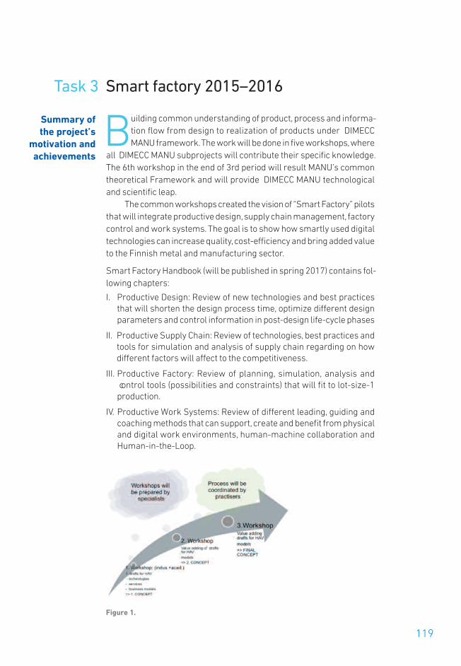
119
Task 3 Smart factory 2015–2016
Building common understanding of product, process and informa-tion flow from design to realization of products under DIMECCMANU framework. The work will be done in five workshops, where
all DIMECC MANU subprojects will contribute their specific knowledge.The 6th workshop in the end of 3rd period will result MANU’s commontheoretical Framework and will provide DIMECC MANU technologicaland scientific leap.
The common workshops created the vision of “Smart Factory” pilotsthat will integrate productive design, supply chain management, factorycontrol and work systems. The goal is to show how smartly used digitaltechnologies can increase quality, cost-efficiency and bring added valueto the Finnish metal and manufacturing sector.
Smart Factory Handbook (will be published in spring 2017) contains fol-lowing chapters:
I. Productive Design: Review of new technologies and best practicesthat will shorten the design process time, optimize different designparameters and control information in post-design life-cycle phases
II. Productive Supply Chain: Review of technologies, best practices andtools for simulation and analysis of supply chain regarding on howdifferent factors will affect to the competitiveness.
III. Productive Factory: Review of planning, simulation, analysis and control tools (possibilities and constraints) that will fit to lot-size-1production.
IV. Productive Work Systems: Review of different leading, guiding andcoaching methods that can support, create and benefit from physicaland digital work environments, human-machine collaboration andHuman-in-the-Loop.
Figure 1.
Summary ofthe project’s
motivation andachievements

The objectives of the Smart Factory task was to enhance cooperation be-tween all DIMECC MANU projects and build common understanding ofproduct, process and information flow from design to realization of prod-ucts under DIMECC MANU framework. The work was done in five work-shops, where all DIMECC MANU sub-projects contributed their specificknowledge. In collaboration with the common workshops the aim wasto build Smart Factory pilots to show how smartly used digital technolo-gies can increase quality, cost-efficiency and bring added value to theFinnish metal and manufacturing sector. The pilots were implementedin production and supply chain simulations in two manufacturing com-panies.
State of the art
Today’s business, especially manufacturing, environments are charac-terized by rapidly changing requirements in terms of customized prod-ucts, unpredictable demand, small batch sizes and very limited accessto actual operational data. The finding is that in relation to digitalizationa lot of companies could have gained profits from new products via ex-ports and incoming orders if investments and up-date of production con-cepts were decided in time.
• The manufacturing systems and networks should adapt rapidly tothese frequent changes and disturbances that cannot be foreseen. Un-fortunately, the readiness to adopt digitalization in this field is stagnat-ing. The ICT tools used in many of the companies currently used in de-sign, manufacturing, operation control and maintenance have beencreated for the old markets where the mass-customization was anorm.
• One of the greatest challenges lay in ICT solutions, which have beendeveloped as stand-alone systems. Connectivity to other systems out-side the immediate application domain has not been realized.
• The digital information flow desperately needed today, does not existyet. This is one of the barriers for export business in many companies.The operability and speed of a manufacturing network slows down,and costs of operation increase dramatically leading to low cost-effi-ciency in Finland.
For example the data from the manufacturing systems is heterogeneous:the quantities might differ, there is no shared structure, and even the low-est-level bit structure can differ. Besides, the setting in a factory is notstable: machines are installed, removed and updated. In addition, theamount of data generated by the manufacturing systems grows fast withincreasing number of sensors and data logging from the interconnectedsystems. Because of these problems the operational data is still not col-
120

121
lected efficiently in companies. Moreover, even if it is collected, it’s notprocessed and used in such way that Finnish companies could take ad-vantage of digital quality management, big data and industrial Internetpossibilities.
Smart Factory concept – Generation of new ideas
The generation of ideas for the Smart Factory concept started with theindustrial workshops. The objectives of the first workshop were to forma common understanding of the present state of manufacturing compa-ny’s process digitalization including the current technology and its usagein companies. Another objective was to form a common understandingof possibilities of digitalization in manufacturing company in time spansof 0–3, 3–5 and 5–10 years. Digitalization current state and future pos-sibilities were considered in three areas: sales and tendering process,design process and order delivery process.
1. Digitalizing the information flow: In the current state the main issueswas related to the facts that there is many different software in useand lots of manual work done in different stages. The main possibilitiesin tendering and design process were heading gradually from soft-ware integrations/reduction and real time data to modular productstructure and digital sales configurator. In production side the devel-opment path were thought to start from re-planning the material flowsand start to gathering real time data. In 3–5 year time span there wereplanned among others PDM/CAD system integration to the productionmachines. Finally in the 5–10 year time span there was robotizationand automatization of production as well as digital logistics planningand simulation of installation process.
2. Optimization on different levels: The objective of optimization work-shop was to find new targets where optimization can be used. The op-timization means finding the optimal solution to the problem byanalysing facts. By analysing large amount of data and using specificoptimization algorithms, excellent results are got for example fromstructure design and cost optimization. The benefits of optimizationincludes transparency through identified objectives, better resultssince a computer can check larger search space rather than a few can-didate designs and faster design process. In the workshop 21 possibletargets for optimization were found from participants business includ-ing among others production control, automatic warehouse, productmodularization, resource efficiency, container ship load maximizationand material waste optimization in machine workshop. Five of thosewere processed further by defining objectives, design variables andconstraints of the problems. In the production control optimization the

objective was defined as cutting throughput time; the parameterswere production batch size, control methods and amount of workshifts; and constrain is the need to keep current system and layout.This same production control case was also further processed in an-other Smart Factory pilot.
3. Digital Information Flows and System Architecture: The objectives ofthe third workshop was to clarify bottlenecks of systematic work andflow of information in supply chain, clarify possibilities of configurationin order delivery process and create a roadmap to develop informationflow in supply chain. In the case company configurable products haveaffected so far only design part in order delivery process. Two differentareas were considered: sales-design interface and design-purchasinginterface. Here again the main challenges in current state are relatedto use of many different software and manual work stages. Also han-dling the revisions during the order-delivery process is sometimeschallenging. In sales-design interface the main development workwere planned to focus on sales configurator and integrating that to ex-isting design configurator. In the design-purchasing interface the de-velopment path starts for example from reducing use of excel filesand taking partners along to the development work. The long termgoal is one digital company where also partners and subcontractorsare deeply integrated.
4. Tracking and Tracing in Production: The objectives of the fourth work-shop were to build common knowledge of state-of-the-art trackingand tracing methods and also the future goals in that area. Third ob-jective was to build a roadmap in ten year time span. Tracing is manda-tory in some business areas nowadays but the benefits to manufac-turing in general are essential. Knowing where the materials comefrom and what have been done to the product during productionprocess and in use, is beneficial to quality control and essential infor-mation for the end user of the product. A company could for examplesell digital fingerprint of products as separate extra information to thecustomer. By adding sensors to the product, for example the end useconditions can be monitored, which could be also sold as an extra serv-ice. Tracking the material real time in production helps for examplesignificantly production control and is essential addition to sensorsand machine vision in highly automated production. The methods fortracking and tracing discussed in the workshop included RFID tags,bar codes and gateways in production.
5. Quality Control and Tracing by Digital Means:Fifth workshop was heldin Mapvision Ltd. In the workshop they introduced their state-of-the-art machine vision aided quality control and tracing methods. Their in-novative measuring cell uses tens of machine vision cameras to meas-
122

123
ure all of the parts in customer’s production line. That kind of cell isused for example in car industry to measure weld seam quality andadjust the welding process in-line by using the measurement data.The case example showed the complete traceability of the operationscan indeed be achieved.
Figure 2. Intelligent robot assisted welding cell
Based on the workshop input and international benchmarking the fol-lowing aims were identified to be in the core of the Smart Factory concept.The Smart Factory concept aims developing a concept where the infor-mation flow is ensured throughout the life-cycle phases the product andthe production system may have. At the core of the Smart Factory con-cept there are following high-level targets:
• Digital twins of the product and manufacturing system that allowsas realistic (and relevant) as possible simulations targeting to futurescenarios to be created and updated.
• Context-aware systems, as a system is always part of a wider system.The entities are communicating with other entities, whether they arepart of the same enterprise or existing in the manufacturing network.
• Support for system level adaptationconsisting of (semi)autonomousand co-operative manufacturing entities, capable of fulfilling their owntasks, and of operating together with other entities.
• Knowledge-based manufacturing entities, capable of developing andlearning from the actions, constantly updating their skill and knowl-edge for future operations.
• Service-oriented activities, where the communication between theentities is seen as services. Only needed information is included in theservices and the skills and knowledge are kept as the autonomy of theentities.
• Formally presented product and manufacturing system informationensuring that the information and knowledge exists only once in a for-mal and up-to-date form available and understandable to all relatedparties.

The Smart Factory information system architecture accomplishing theefficiency and digitalization goals, comprises four levels, see Figure 3.The first one is the shop floor level, which represents the whole produc-tion environment with its respective resources. The generated informa-tion, due to the production process, comprehends of energy related sen-sory data. The information is then analyzed, reasoned and processed inthe second level, the data level, and are thus made usable for planning,decision-making and control purposes accomplished on the third level,the planning and adaptation level. On the fourth level, the business man-agement level, the KPI information is used to aid in the business deci-sion-making. A schematic draft of the system architecture is presentedin the following.
Figure 3. Levels of the Smart Factory concept
Smart Factory pilots
The pilot cases are simulation studies for smart industrial value chain.Both of them are implemented using combination of spreadsheet anddiscrete-event simulation software packages. The pilot cases are mod-eled using Siemens Tecnomatix Plant Simulation software. Simulationmodels can be built both in 2D- and 3D-environments. Simulation resultscan be viewed inside the software and the data can also be exported togenerate the results in different software e.g. in MS Excel.
124

125
The case Ruukki is a simulation study for steel truss process. Theprocess consists of material storage, blasting and sawing, assemblywelding, surface treatment and storage area of finished products. Be-tween each phase of the process is a buffer area for work in process.Some of the parts are subcontracted because they need manufacturingmethods that doesn’t exist in the main factory. The aim of the case is toobserve bottlenecks and throughput times of the process as well as ex-perimenting different scenarios for future operation principles of the fac-tory. Currently the gathering of the needed input data for the simulationmodel is an ongoing process. Simulation experiments can be done onlyafter the input data is implemented into the simulation model.
The case Katsa is a simulation study for part manufacturing processof gearwheels, gear shafts, gear rings and gear couplings as well as slew-ing bearings. The process includes several facilities in different locations,subcontracting locations, and logistics between the locations. The vari-ation of the parts is large and they have numerous different value chains.The main goal is experimenting different production planning and controlprinciples. These include applying theory of constraints managementparadigm for key resources, dedicating selected resources for specificpart families, and finding bottlenecks of the value chains. Also in thiscase, the gathering of the input data is currently in process.
The pilot cases are somewhat different but both of them focus onimproving the manufacturing activities within a company. Similar to bothof the cases is to identify bottlenecks and to find means to avoid them.Also the main areas of the pilot cases are similar. Figure 4 presents thosemain areas of the pilot cases.
Figure 4. Main areas of the pilot cases

The design tool is a specific tool used in the case Ruukki and it was de-veloped during the DIMECC MANU program. It represents the source ofinformation used in the building of the simulation model. In the Katsacase, similar information was gathered from enterprise resource plan-ning (ERP) software. In both cases the required information includedproduct, process, and resource data. The required information is builtaround the process data, which means the flow of the products i.e. theprocess chain in the modeled manufacturing system. The product dataincludes e.g. the product portfolio used in the simulation experimentsand some product specific parameters. The resource data holds process-ing times and capacity, and in some resources also, for example, setuptimes.
The gathered product, process, and resource data is then storedand manipulated in independent software that in the pilot cases was MSExcel due to its wide usage in companies. This data was used for simu-lation data and rules to construct the structure and behavior of the sim-ulation model. Simulation parameters were used to create different sim-ulation scenarios. Examples of the simulation parameters used in thecase Ruukki were:
• Production program – altering the start dates of the products.
• Production batch – altering the number of products in the batches.
• Working time – selecting 1–3 shifts for each resource individually. Oneshift represents eight hours while three shifts covers a whole day.
• Number of resources – defining the number of parallel resources foreach resource individually.
Figure 5 presents an overview of the simulation model of case Ruukki.The objects represent resources and storages while the different func-tional areas are color-coded. The simulation model is built on 2D factorylayout. Due to the aims of the pilot case, realistic looking 3D-graphicswere not considered to bring more value to the simulation experiments.
Figure 5. Illustration of the case Ruukki simulation model
126

127
Several simulation runs were conducted altering the simulation param-eters. After each simulation run, the results were analyzed and their ap-plicability was assessed. The simulation model indicated what is the ef-fect of altering a simulation parameter but doesn’t necessarily tell howthe actual change could be implemented. Figure 6 shows an example ofthe results from a simulation experiment. In this example the productionof two batches of 10 products were simulated with certain parametersof parallel resource and number of shifts. The bar shows the totalthroughput time of the products and the different colors indicate howlong the product has spent in a certain part of the factory.
Figure 6. Example of simulation results
At the end of the simulation study the results were reported for a biggeraudience. Selected results from the different simulation experimentswere selected in that they clearly show the effect of altering the simula-tion parameters.
CONTACT PERSONS:
Muuta: Kai Syrjälä, Kaidoc OyMinna Lanz, Tampere University of Technology
PARTICIPANTS:
TUT, VTT, Kaidoc Oy, Ruukki, Katsa, MacGregor, Mapvision, Fastems, Raute.
Furtherinformation

DIMECC OyKorkeakoulunkatu 7, 33720 Tampere, Finland
DIMECC Factory, Oulu
DIMECC Factory, Tampere
DIMECC Factory, Turku
DIMECC Factory, Espoo
WWW.DIMECC.COM
ISBN 978-952-238-176-7978-952-238-177-4 (pdf)DIMECC Publication seriesISSN 2342-2696 (online)
FINAL R
EPORT 2/2016
MANU – Future D
igital Man
ufacturing Tech
nologies an
d System
s
D IMECC Program MANU
D


