FORMRFE 0219 COMANDO DA AERONÁUTICA CENTRO DE INVESTIGAÇÃO E PREVENÇÃO DE ACIDENTES AERONÁUTICOS FINAL REPORT A – 066/CENIPA/2014 OCCURRENCE: ACCIDENT AIRCRAFT: PR-OAF MODEL: F28MK0100 DATE: 28MAR2014
Transcript
FORMRFE 0219
COMANDO DA AERONÁUTICA
CENTRO DE INVESTIGAÇÃO E PREVENÇÃO DE ACIDENTES AERONÁUTICOS
FINAL REPORT
A – 066/CENIPA/2014
OCCURRENCE: ACCIDENT
AIRCRAFT: PR-OAF
MODEL: F28MK0100
DATE: 28MAR2014
A-066/CENIPA/2014 PR-OAF 28MAR2014
2 of 28
NOTICE
According to the Law nº 7565, dated 19 December 1986, the Aeronautical Accident
Investigation and Prevention System – SIPAER – is responsible for the planning, guidance,
coordination and execution of the activities of investigation and prevention of aeronautical accidents.
The elaboration of this Final Report was conducted taking into account the contributing
factors and hypotheses raised. The report is, therefore, a technical document which reflects the result
obtained by SIPAER regarding the circumstances that contributed or may have contributed to
triggering this occurrence.
The document does not focus on quantifying the degree of contribution of the different
factors, including the individual, psychosocial or organizational variables that conditioned the
human performance and interacted to create a scenario favorable to the accident.
The exclusive objective of this work is to recommend the study and the adoption of provisions
of preventative nature, and the decision as to whether they should be applied belongs to the President,
Director, Chief or the one corresponding to the highest level in the hierarchy of the organization to
which they are being forwarded.
This Report does not resort to any proof production procedure for the determination of civil
or criminal liability, and is in accordance with Appendix 2, Annex 13 to the 1944 Chicago
Convention, which was incorporated in the Brazilian legal system by virtue of the Decree nº 21713,
dated 27 August 1946.
Thus, it is worth highlighting the importance of protecting the persons who provide
information regarding an aeronautical accident. The utilization of this report for punitive purposes
maculates the principle of “non-self-incrimination” derived from the “right to remain silent”
sheltered by the Federal Constitution.
Consequently, the use of this report for any purpose other than that of preventing future
accidents, may induce to erroneous interpretations and conclusions.
N.B.: This English version of the report has been written and published by the CENIPA with the
intention of making it easier to be read by English speaking people. Taking into account the
nuances of a foreign language, no matter how accurate this translation may be, readers are
advised that the original Portuguese version is the work of reference.
A-066/CENIPA/2014 PR-OAF 28MAR2014
3 of 28
SYNOPSIS
This is the Final Report of the 28MAR2014 accident with the F28MK0100 aircraft, registration PR-OAF. The accident was classified as “[SCF-NP] System/Component Failure or Malfunction Non-Powerplant / With Landing Gear”.
Thirty minutes after takeoff, the aircraft had a low level of the hydraulic system 1. The flight proceeded to its destination with this degraded hydraulic system.
During the landing procedures, the crew used the alternative system for lowering the landing gears. The two main landing gears lowered and locked, but the nose landing gear remained up.
During the landing run, the main landing gears and the lower part of the front fuselage supported the aircraft. Substantial damage to structural elements occurred near the nose section. There was no fire.
The copilot suffered fractures in the thoracic spine. The other crewmembers and the passengers left unharmed.
An Accredited Representative of the Dutch Safety Board (DSB) - Netherlands, (State where the aircraft was designed and manufactured) and an Accredited Representative of the Air Accidents Investigation Branch (AAIB) – United Kingdom, (State where the component Engine-Driven Pump (EDP) was manufactured) were designated for participation in the investigation.
A-066/CENIPA/2014 PR-OAF 28MAR2014
4 of 28
CONTENTS
1.1 History of the flight. ........................................................................................................ 6
1.2 Injuries to persons.......................................................................................................... 6
1.3 Damage to the aircraft. .................................................................................................. 6
1.4 Other damage. ............................................................................................................... 8
TPR Aircraft Registration Category of Regular Public Transport
UTC Universal Time Coordinated
VFR Visual Flight Rules
A-066/CENIPA/2014 PR-OAF 28MAR2014
6 of 28
FACTUAL INFORMATION.
Aircraft
Model: F28MK0100 Operator:
Registration: PR-OAF Oceanair Airlines S.A.
Manufacturer: Fokker
Occurrence
Date/time: 28MAR2014 - 2042 UTC Type(s):
Location: Presidente Juscelino Kubitschek International Airport (SBBR)
[SCF-NP] System/Component Failure or Malfunction Non-Powerplant
Lat. 15°52’16”S Long. 047°55’07”W Subtype(s):
Municipality – State: Brasília – DF With Landing Gear
1.1 History of the flight.
The aircraft took off from the Senador Nilo Coelho Aerodrome (SBPL), Petrolina - PE, to Presidente Juscelino Kubitschek International Airport (SBBR), Brasilia - DF, at 1752 (UTC), in order to complete the scheduled cargo and personnel flight O6 6393, with 5 crewmembers and 44 passengers on board.
During the level flight, thirty minutes after takeoff, the aircraft presented low level in the hydraulic system 1. The crew performed the planned operational procedures and continued the flight to Brasilia, with the hydraulic system degraded.
During the SBBR landing procedures, the crew used the alternative system for lowering the landing gears. The main landing gears lowered and locked, the nose landing gear unlocked, but did not lower.
After coordination with the air traffic control, the aircraft was instructed to land on SBBR runway 11R.
The landing took place at 2042 (UTC). After the touchdown, the aircraft covered a total distance of 900 meters until its full stop. The initial 750 meters were with the aircraft supported only by the main landing gears and the last 150 meters were with the aircraft supported by the main landing gears and by the lower part of the front fuselage. The aircraft stopped on the runway.
Substantial damage to structural elements of the aircraft occurred near the nose section.
The evacuation of the crewmembers and passengers was safe and orderly.
The copilot suffered fractures in the thoracic spine. The other crewmembers and passengers left unharmed.
1.2 Injuries to persons.
Injuries Crew Passengers Others
Fatal - - -
Serious 1 - -
Minor - - -
None 4 44 -
1.3 Damage to the aircraft.
The aircraft had substantial damage to structural elements near the nose section.
A-066/CENIPA/2014 PR-OAF 28MAR2014
7 of 28
Figure 1 - Aircraft after its stop on the runway.
The coating of the nose landing gear doors and the surrounding area has been severely worn, eventually breaking up, due to friction against the runway surface.
Figure 2 - Detail of the damage after lifting the aircraft and lowering the nose landing gear.
The fuselage coating, in an area in front of the passengers’ door, was deformed and some rivets "worked".
Figure 3 - Detail of the deformation in the coating and deformed rivets.
In the inner region of the fuselage, in front of the nose landing gear housing, there was the deformation of the structural elements (LH and RH stiffner), where the FWD pressure bulkhead skin was attached.
A-066/CENIPA/2014 PR-OAF 28MAR2014
8 of 28
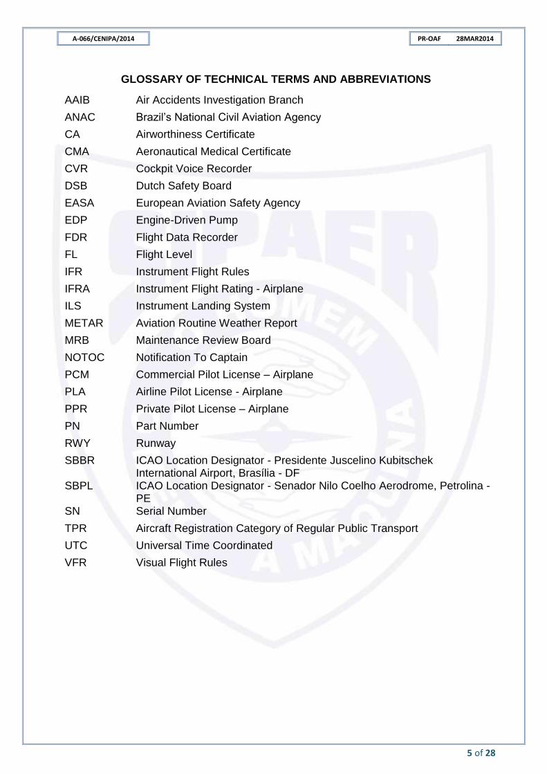
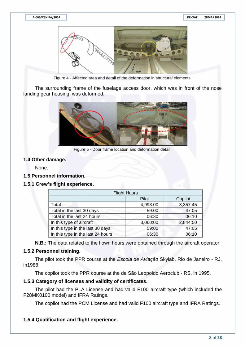
Figure 4 - Affected area and detail of the deformation in structural elements.
The surrounding frame of the fuselage access door, which was in front of the nose landing gear housing, was deformed.
Figure 5 - Door frame location and deformation detail.
1.4 Other damage.
None.
1.5 Personnel information.
1.5.1 Crew’s flight experience.
Flight Hours
Pilot Copilot
Total 4,993:00 3,357:45
Total in the last 30 days 59:00 47:05
Total in the last 24 hours 06:30 06:10
In this type of aircraft 3,060:00 2,844:50
In this type in the last 30 days 59:00 47:05
In this type in the last 24 hours 06:30 06:10
N.B.: The data related to the flown hours were obtained through the aircraft operator.
1.5.2 Personnel training.
The pilot took the PPR course at the Escola de Aviação Skylab, Rio de Janeiro - RJ, in1988.
The copilot took the PPR course at the de São Leopoldo Aeroclub - RS, in 1995.
1.5.3 Category of licenses and validity of certificates.
The pilot had the PLA License and had valid F100 aircraft type (which included the F28MK0100 model) and IFRA Ratings.
The copilot had the PCM License and had valid F100 aircraft type and IFRA Ratings.
1.5.4 Qualification and flight experience.
A-066/CENIPA/2014 PR-OAF 28MAR2014
9 of 28
The pilots were qualified and had experience in the kind of flight.
1.5.5 Validity of medical certificate.
The pilots had valid CMAs.
1.6 Aircraft information.
The aircraft, serial number 11415, was manufactured by Fokker, in 1992 and it was registered in the TPR category.
The aircraft had valid Airworthiness Certificate (CA).
The technical maintenance records were updated.
Scheduled maintenance had been performed in accordance with current regulations and maintenance manuals.
At the time of the accident, the aircraft had 44,449 hours and 32,602 total operating cycles.
The aircraft was equipped with two independent hydraulic systems, identified as system 1 and system 2. The systems were identical in concept and performance, differing only in capacity and supplied subsystems. System 1 supplied the left aileron, rudder, elevator, stabilizer, alternative brake, landing gear, directional control of the nose landing gear, flaps, speed brakes, lift dumpers and thrust reversers. System 2 supplied the right aileron, rudder, elevator, stabilizer and normal brakes.
In the event of failure of one of the hydraulic systems, the operation of the elevators and rudder was not affected. The effort to control the aileron would be greater than in normal operation.
The main components of each system consisted of a tank, two mechanical hydraulic pumps - Engine-Driven Pumps (EDP) 1 and 2, an electric hydraulic pump, double fire shut-off valve and pressure accumulator. There was a priority valve installed on system 1. The systems were controlled from the hydraulic panel in the cockpit.
Mechanical hydraulic pumps (EDP) were able to pressurize the system with 3,000 PSI. Two EDP were installed on each aircraft engine, one pressurizing the system 1 and the other the system 2. When the fire lever was actuated, the associated shutoff valve closed and isolated the EDP from its engine and tank supply line of each system. The operation of the hydraulic system was not affected during a single engine flight.
A low capacity electric pump was installed in each system. The main purpose was to test the system for maintenance actions and could also be used to pressurize the brake system before starting the engines.
The priority valve would close if system 1 pressure dropped below a preset value, to ensure hydraulic power remained available for flight controls, speed brakes and thrust reversers. The valve would open to restore hydraulic power to the landing gear, nose landing gear directional control, lift dumpers, alternative brakes and flaps when pressure rose above a preset value.
The landing gear was retracted and lowered by the hydraulic system. In the event of system 1 failure, the landing gear could be lowered by gravity.
On the main landing gears, when the lever was selected for up or down, the internal doors of the landing gear bay would be hydraulically unlocked and opened. When the inner doors fully opened, the main landing gears would retract or lower down, and when the landing gears were fully extended or retracted, the bay's internal doors would close hydraulically and lock mechanically.
A-066/CENIPA/2014 PR-OAF 28MAR2014
10 of 28
Main landing gears were locked mechanically. The landing gear down locks were hydraulically unlocked when the landing gear was retracted. The main landing gears were held in the retracted position by hydraulic force and, in the event of loss of power, the internal doors would support them. The outer doors of the landing gear bay were connected to the landing gears structure, opened and closed mechanically, following its movement.
On the nose landing gear, when the lever was selected for up, the landing gear was hydraulically unlocked and retracted. When the landing gear was fully retracted, the doors would close hydraulically and lock mechanically. The landing gear was held in its retracted position by hydraulic power, and in the event of loss of power, these doors would support the landing gears.
When the lever was selected to down, the nose landing gear doors were unlocked and hydraulically opened. When the doors were fully open, the nose landing gear would extend and lock down mechanically and the doors would remain open.
The landing gear selector lever, located on the center instrument panel, operated a selector valve that directed system 1 pressure according to the up or down position. Sequence valves ensured that the doors opened and remained open while the main and nose landing gears were in transit.
The selector lever for alternating landing gear operation was located at the rear, on the right side of the pedestal between the pilots. When commanded to the extend position, it released the landing gear door locks and relieved pressure from the hydraulic system.
The landing gears extended by gravity and locked down mechanically. The internal doors of the main landing gears remained open and were protected from damage by structural elements called slide strips. The nose landing gear directional system was rendered inoperable after an alternating landing gear operation.
The landing gear indication system had position lights for each of the landing gears located below the selector lever. The indication was as follows:
- landing gear down and locked - green light on for the respective landing gear; and
- landing gear up and locked - light off for the respective landing gear.
In normal operation, a blue light, incorporated into the selector lever, turned on during the landing gear retraction and stayed on until all landing gear doors were closed and locked. During the lowering of the landing gears, the light turned on and stayed on until all the landing gears were lowered and locked.
In an alternating system operation, the blue light turned on and stayed on until the selector lever was set to the down position and until all landing gears were down and locked.
A-066/CENIPA/2014 PR-OAF 28MAR2014
11 of 28
Figure 6 - Location of the blue light and the green ones.
The doors were built, internally, with honeycomb panels aluminum alloy-covered and exterior coating panels. The panels were stiffened by reinforcing plates. A bracket was installed inside the door to connect the door bracket. There was a hinge assembly installed on the outer lateral end of the door.
Figure 7 – Landing gear doors, bracket and hinge.
The maintenance requirements for landing gear doors were as follows:
- Maintenance Review Board (MRB) task 322201-00-01 - lubrication of articulation mechanisms every 3,600 flight hours;
- MRB task 322201-00-02 - detailed inspection of the door operating device, including the hinging mechanism every 5,000 hours of flight; and
A-066/CENIPA/2014 PR-OAF 28MAR2014
12 of 28
- MRB task 323300-00-02 - functional check of alternating landing gear system command every 4,000 flight hours.
In the aircraft maintenance history, specifically with regard to the services performed in the landing gear door area, it was found that in September 2012, the right door hinges were repaired by incorporating larger radial pins and enlargement of the lobe holes. This service was performed at Fokker Services B. V. base in Hoofddorp, the Netherlands.
In Figure 8, the pin can be identified through the red arrow, the hinge lobe connected to the fuselage through the blue arrow and the hinge lobe connected to the door through the green arrow.
Figure 8 - Detail of the hinges.
Still, checking the history of the maintenance actions performed by the operator, it was found that both scheduled and unscheduled maintenance actions, were performed in accordance with the requirements in force at the time.
In the records of the aircraft maintenance technical book, referring to the day of the accident and the previous two days, there were no notes related to the hydraulic system or to fluid leaks from the engines.
1.7 Meteorological information.
The METAR of the SBBR provided the following information:
The weather conditions were favorable for the visual flight, the wind was calm and the visibility was over 10km.
It was also found that there were no unfavorable weather conditions during the flight from SBPL to SBBR.
1.8 Aids to navigation.
The aids needed for the ILS approach to the RWY 11R were working properly.
A-066/CENIPA/2014 PR-OAF 28MAR2014
13 of 28
1.9 Communications.
Nil.
1.10 Aerodrome information.
The Aerodrome was public/military, run by the INFRAMERICA and operated under Visual (VFR) and Instrument Flight Rules (IFR), day and night.
The runway was made of asphalt, with 11R/29L thresholds, dimensions 3,300m x 45m, with elevation of 3,497 feet.
1.11 Flight recorders.
The aircraft was equipped with a FA2100 L-3 Flight Data Recorder (FDR), Part Number (PN) 2100-4043-00, Serial Number (SN) 528094, and a Cockpit Voice Recorder -CVR L-3, model FA2100, PN 2100-1020-00, SN 152278, capable of recording for two hours.
1.12 Wreckage and impact information.
Due to the non-lowering of the nose landing gear, the impact of the fuselage occurred on the runway. The aircraft had substantial damage to structural elements near the nose section.
After the impact, there was no detachment of the aircraft parts, which remained within the runway boundaries after the landing run.
Figure 9 - Mark of the first fuselage impact.
1.13 Medical and pathological information.
1.13.1 Medical aspects.
Nil.
1.13.2 Ergonomic information.
Nil.
1.13.3 Psychological aspects.
Nil.
1.14 Fire.
There was no fire.
A-066/CENIPA/2014 PR-OAF 28MAR2014
14 of 28
1.15 Survival aspects.
Passengers and crewmembers left the aircraft through the front, left and right doors, using their scape slides. The copilot was assisted by firefighters to disembark. The pilot was the last to leave the aircraft.
1.16 Tests and research.
About an hour after the accident, the field investigation action team verified in the cockpit that the landing gear selector lever was in the landing gear down position, LG DOWN.
Figure 10 - Landing gear lever in the down position, LG DOWN.
The landing gear alternative control lever was in the extend position.
Figure 11 - Landing gear alternative control lever in the extend position.
The amount of hydraulic fluid indicated on the panel above the pilots’ head, in the upper left corner of the flight cabin, referring to system 1, was of 0%.
Figure 12 - Hydraulic panel detail and amount of fluid in the system 1.
A-066/CENIPA/2014 PR-OAF 28MAR2014
15 of 28
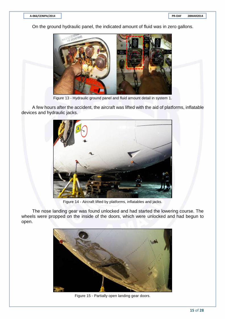
On the ground hydraulic panel, the indicated amount of fluid was in zero gallons.
Figure 13 - Hydraulic ground panel and fluid amount detail in system 1.
A few hours after the accident, the aircraft was lifted with the aid of platforms, inflatable devices and hydraulic jacks.
Figure 14 - Aircraft lifted by platforms, inflatables and jacks.
The nose landing gear was found unlocked and had started the lowering course. The wheels were propped on the inside of the doors, which were unlocked and had begun to open.
Figure 15 - Partially open landing gear doors.
A-066/CENIPA/2014 PR-OAF 28MAR2014
16 of 28
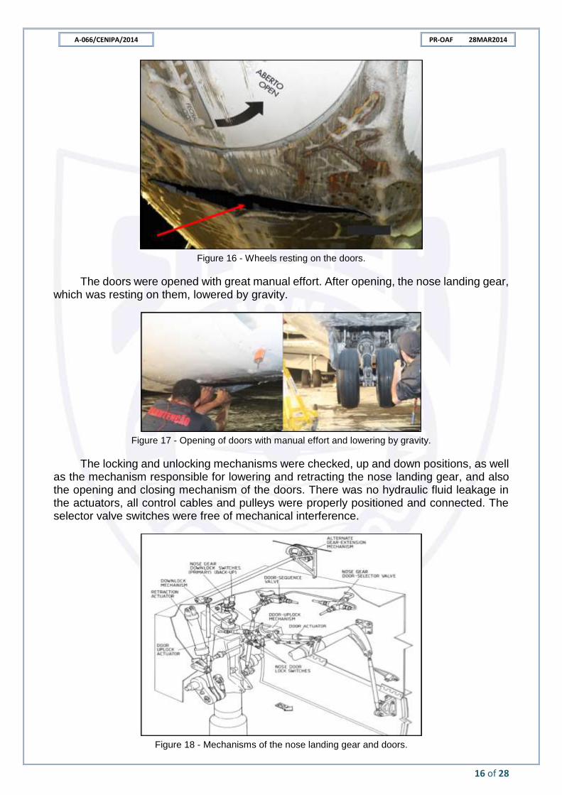
Figure 16 - Wheels resting on the doors.
The doors were opened with great manual effort. After opening, the nose landing gear, which was resting on them, lowered by gravity.
Figure 17 - Opening of doors with manual effort and lowering by gravity.
The locking and unlocking mechanisms were checked, up and down positions, as well as the mechanism responsible for lowering and retracting the nose landing gear, and also the opening and closing mechanism of the doors. There was no hydraulic fluid leakage in the actuators, all control cables and pulleys were properly positioned and connected. The selector valve switches were free of mechanical interference.
Figure 18 - Mechanisms of the nose landing gear and doors.
A-066/CENIPA/2014 PR-OAF 28MAR2014
17 of 28
In these mechanisms conditions were not identified that could impose restrictions on the unlocking of the up position of the landing gear and the proper functioning of the lowering mechanism.
It was found that the rods responsible for opening and closing the landing gears doors suffered plastic deformation, caused by buckling, due to an axial compression effort. After lowering the nose landing gear, the rods separated into two sections each with slight manual effort.
Figure 19 - Deformed rods.
Figure 20 - Effort in the rod and bent area, partially sectioned.
The deformation found was compatible with a dynamics in which the door mechanism acted to open them, imposing an axial effort on the rods. The doors, in turn, did not open completely and consequently produced a reaction force on the rods, resulting in
A-066/CENIPA/2014 PR-OAF 28MAR2014
18 of 28
compression. The compression effort became greater when the fuselage touched the ground and forced the doors closed, which resulted in buckling and subsequent bending of the rods.
Research conducted on the aircraft in the days following the accident, focused on the hydraulic system.
Upon finding that the reservoir of the hydraulic system 1 was empty, a search for the source of the fluid leak started.
It was identified that the left engine EDP1 was experiencing hydraulic fluid leakage.
Figure 21 - Left engine and EDP1 detail.
The EDP1 was removed and it was found that there was fluid leakage through the pump body, specifically by the gasket between the sections that make up the pump body, called mounting flange and housing.
Figure 22 - EDP1 installed and after removal.
Figure 23 - Detail of the gasket leak in the body of the EDP1.
A-066/CENIPA/2014 PR-OAF 28MAR2014
19 of 28
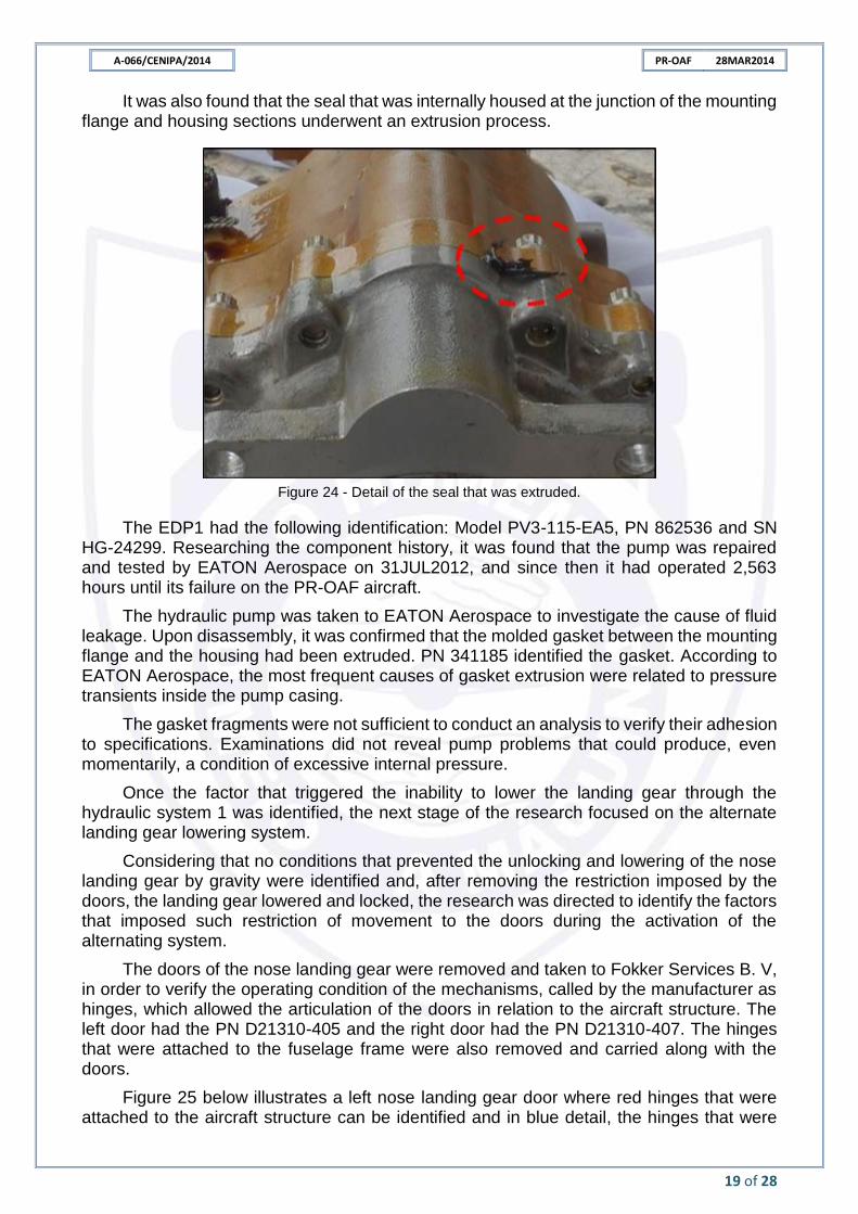
It was also found that the seal that was internally housed at the junction of the mounting flange and housing sections underwent an extrusion process.
Figure 24 - Detail of the seal that was extruded.
The EDP1 had the following identification: Model PV3-115-EA5, PN 862536 and SN HG-24299. Researching the component history, it was found that the pump was repaired and tested by EATON Aerospace on 31JUL2012, and since then it had operated 2,563 hours until its failure on the PR-OAF aircraft.
The hydraulic pump was taken to EATON Aerospace to investigate the cause of fluid leakage. Upon disassembly, it was confirmed that the molded gasket between the mounting flange and the housing had been extruded. PN 341185 identified the gasket. According to EATON Aerospace, the most frequent causes of gasket extrusion were related to pressure transients inside the pump casing.
The gasket fragments were not sufficient to conduct an analysis to verify their adhesion to specifications. Examinations did not reveal pump problems that could produce, even momentarily, a condition of excessive internal pressure.
Once the factor that triggered the inability to lower the landing gear through the hydraulic system 1 was identified, the next stage of the research focused on the alternate landing gear lowering system.
Considering that no conditions that prevented the unlocking and lowering of the nose landing gear by gravity were identified and, after removing the restriction imposed by the doors, the landing gear lowered and locked, the research was directed to identify the factors that imposed such restriction of movement to the doors during the activation of the alternating system.
The doors of the nose landing gear were removed and taken to Fokker Services B. V, in order to verify the operating condition of the mechanisms, called by the manufacturer as hinges, which allowed the articulation of the doors in relation to the aircraft structure. The left door had the PN D21310-405 and the right door had the PN D21310-407. The hinges that were attached to the fuselage frame were also removed and carried along with the doors.
Figure 25 below illustrates a left nose landing gear door where red hinges that were attached to the aircraft structure can be identified and in blue detail, the hinges that were
A-066/CENIPA/2014 PR-OAF 28MAR2014
20 of 28
attached to the aircraft structure doors. A pin through the lobe holes of each of the hinges promoted the union of the two frames, door and fuselage.
Figure 25 - Drawing of the left door and detail of the hinges.
Figure 26 - Left door and front hinge detail.
Figure 27 - Right door and rear hinge detail.
A-066/CENIPA/2014 PR-OAF 28MAR2014
21 of 28
Figure 28 - Right front door hinge and pin detail.
Figure 29 - Inner area of the right hinge front door lobe and detail of the scratches.
Tests and examinations of material taken to Fokker Services B. V. have highlighted the following:
- the right door hinge, which was connected to the fuselage, was arched;
- the hinges on both doors showed no signs of recent lubrication;
- the left door hinges could move freely;
- it was not possible to move the hinges of the right door with natural manual effort;
- the movement of the hinges between the right door and the aircraft frame was occurring with interference;
- the interference in the hinges movement was evidenced by the scratches on the hinges pins and on the internal area of the hinges lobes. This was observed on all right-door hinges;
- the radial measurements of the lobes pins and holes, despite the interference observed in the connections, did not present deviations from the standard dimensions and, consequently; could not be mentioned as a contributing aspect to the restriction to moving of hinges; and
- it was found that the force exerted by the nose landing gear when it was propped against the doors would not be sufficient to open them.
A-066/CENIPA/2014 PR-OAF 28MAR2014
22 of 28
Further research was conducted so that the hinges were sectioned so that the internal relief of the lobe surface could be better observed. The result indicated that there was expansion of the superficial layers, due to an oxidation and corrosion process, which led to a decrease in the inner diameter of the lobes at some points and, consequently, a more intense rubbing of the inner area of the lobes with the pins.
Figure 30 - Sectioned hinges lobes and internal corrosion detail.
1.17 Organizational and management information.
The aircraft belonged to Oceanair Airlines Ltd., a company dedicated to passengers transportation activities.
The maintenance services were performed in accordance with the requirements established by the legislation in force at the time.
1.18 Operational information.
On the same day of the accident, 28MAR2014, the crew that had taken over the aircraft made the first flight from Brasilia to Petrolina, taking off at 1545 (UTC), fulfilling flight O6 6392. The pilots had already performed this route several times.
The aircraft commander had performed the last simulator training in December 2013, about three months before the occurrence.
There were no discrepancies recorded in the aircraft maintenance technical logbook regarding special conditions of the hydraulic system or other items that prevented the flight or limited its performance.
The next flight, with the same crewmembers, took off from SBPL at 1752 (UTC) to SBBR. All flight preparation procedures were performed as provided in the Fokker 100 Airplane Flight Manual.
The aircraft had been refueled in Petrolina with the amount of 3,857 liters, the fuel density was of 0.78 and the water contamination test was performed. The total fuel in the aircraft after refueling was 6,500kg. The minimum required for the leg, according to the operator’s dispatch release was of 5,019kg. The flight plan for the Petrolina - Brasilia leg included the city of Goiânia as an alternative and the planned level was Flight Level 340 (FL340).
The Notification to Captain (NOTOC) for the flight stated that there were no dangerous goods on board the aircraft.
The takeoff weight from Petrolina was of 36,261kg and the expected landing weight in Brasilia was of 33,027kg. The aircraft was within the weight and balance limits specified by the manufacturer.
A-066/CENIPA/2014 PR-OAF 28MAR2014
23 of 28
For the SBPL - SBBR leg, the commander, who occupied the left seat, was expected to stay in the Pilot Monitoring function. The copilot, who occupied the right seat, would be in the role of Pilot Flying. However, due to the situation generated by the hydraulic system failure, the commander switched to the Pilot Flying function.
According to what was obtained by interviewing the crew, with the data in the FDR and the contents of the CVR recordings, the crew followed all procedures provided in the aircraft flight manual (Fokker 100 Airplane Flight Manual, Part 1), in particular as regards Chapter 4 (Abnormal Procedures, 4.07.01 Hydraulics). This procedure was also included in the Fokker 100 Quick Reference Handbook, which was also in the aircraft cabin and was used by the crew.
As predicted for the case, Hydraulic System1 Fail Procedure, the landing gear lowering would have to occur using the alternate system.
In performing SBBR landing procedures, the crew used the alternate system for lowering the landing gears. Main landing gears lowered and locked down. However, the nose landing gear unlocked up but did not lock down, being supported by the landing gear doors. It should be noted that the crew had, through the cabin indications, the information that the main landing gears were locked down and the nose landing gear was in transit.
Given the situation, the crew continued to follow the provisions of the Quick Reference Handbook, Emergency Procedures, Emergency Landings, specifically the procedure called “GEAR UP / UNSAFE LANDING”.
After coordination with the air traffic control body, the aircraft was instructed to land on the RWY 11R of the Brasilia Aerodrome.
The landing took place at 2042 (UTC). After the touchdown, the aircraft covered a total distance of 900 meters, of which the first 750 meters occurred with the aircraft supported by the main landing gears and the remaining 150 meters with the aircraft supported by the main landing gears and the lower part of the front fuselage. The aircraft came to a complete stop on the runway.
1.19 Additional information.
Nil.
1.20 Useful or effective investigation techniques.
Nil.
ANALYSIS.
The crew that took over the flight on 28MAR2014 was qualified, certified and had already performed that same leg several times. The aircraft commander had recently performed simulator training.
All procedures adopted by the crew regarding the management of the fault presented by the hydraulic system 1 occurred in accordance with the provisions of the aircraft operation manuals.
Through the examinations and tests conducted on the aircraft, as well as its components, it was found that the lowering and locking of the nose landing gear through the alternate system would not be possible, due to technical problems, which will be explained throughout the present analysis.
During the investigation, it was found that there was fluid leakage through the body of one of the hydraulic pumps, called EDP 1, which was installed on the left engine of the aircraft. Considering that there was no previous report of the malfunction of the hydraulic system and that the aircraft preparation procedures were carried out satisfactorily before the
A-066/CENIPA/2014 PR-OAF 28MAR2014
24 of 28
Petrolina takeoff, it can be stated that the leak, at least with regard to large proportions of hydraulic fluid, occurred from the takeoff of that locality.
The leak was such that it caused the collapse of the hydraulic system 1 about thirty minutes after takeoff.
Research conducted on the hydraulic pump was sufficient to identify that fluid leakage occurred due to extrusion of a molded gasket. This gasket was between two sections of the pump body in an area that was only worked on when the pump was submitted to repairs or overhaul.
The pump in question had been repaired and tested on 31JUL2012 and since then had operated 2,563 hours until the aforementioned leak had occurred, which resulted in the inoperative hydraulic system 1. The most common factors for gasket extrusion are pressure transients inside the pump casing, however there is no certainty as to what triggered the extrusion of this gasket.
During the approach to the SBBR landing, the crew, while continuing the emergency procedures provided for the hydraulic system 1 failure scenario, commanded the landing gear to be lowered by the alternating system. Main landing gears lowered and locked down. The doors of the nose landing gear unlocked, but didn't open. The nose landing gear unlocked but didn't lower down.
Research conducted on the lowering system of the nose landing gear and also on its doors, showed that the right door had restrictions on free movement. It was not possible to move the door hinges with natural hand effort. In the standard situation, it was expected that there was no restriction on the action to articulate the door, as it was found that there was no such restriction on the left door.
The resistance produced by the hinges, in the sense of articulating the right door, was greater than the force caused by the nose landing gear when driven by the alternating system. In case of activation of the alternating system, the effort exerted on the doors is only due to the weight of the landing gear, there is no hydraulic force for lowering the landing gear and opening the door.
Research conducted on the right door to find out what caused increased resistance to the hinges movement was not conclusive to the point of finding the determining factor.
It was identified that the hinges of this door had undergone structural repairs in September 2012, where there was the incorporation of larger radial pins and widening of the lobes orifices. The radial measurements of these pins and the lobe holes did not deviate from the predicted dimensions.
However, it could not be ruled out that any deviation or non-adhesion to the requirements established for the widening of the holes in the hinges regarding surface finish and corrosion protection could have been occurred.
In the same test, it was verified that the hinges showed no signs of recent lubrication. However, despite the absence of signs of recent lubrication on the door hinges, it was found that all planned maintenance for the aircraft was performed as intended.
When the hinges were sectioned so that the internal relief of the surface of the lobes could be better observed, it was found that there was expansion of the superficial layers due to an oxidation and corrosion process.
In a normal condition, the lowering of the landing gear was controlled by the landing gear selector lever, located on the central instrument panel, and its movement occurred by the action of the hydraulic force provided by the hydraulic system 1.
A-066/CENIPA/2014 PR-OAF 28MAR2014
25 of 28
At the moment when the lowering of the landing gear was commanded by the alternating operation selector lever, moving it to the extend position, what was in action at that moment to provide the lowering of the nose landing gear was only the effort on the doors caused by its weight.
It was found that the force exerted by the weight of the nose landing gear when leaning against the doors was not sufficient to overcome the resistance offered by the right door and result in its opening articular movement together with the left door, thus preventing the lowering of the landing gear.
It should be noted that the verification of the force required to articulate the right door hinges was performed after the accident, when the entire aircraft structure and the region near the nose landing gear had been subjected to unusual efforts.
In this sense, it must be considered that, due to the impact of the fuselage against the runway and subsequent dragging, the force to articulate the hinges could be lower, or even greater than the results found in the applied tests.
A progressive loss in alignment between the door and fuselage hinges, due to efforts resulting from normal aircraft operation, could also contribute to the pin working interfering with the hinge lobe holes.
The left door, although no resistance to its articulating movement was identified, did not open because its movement depended on the movement of the right door.
As could be seen, the doors were mechanically connected to each other. If one of the doors did not open, the other would not open either. The right door movement restriction, which originated from the hinge restriction, prevented the left door opening and it did not open either.
Considering the entire chain of events initiated by the failure of EDP 1 and the fact that all records of maintenance tasks were in accordance with the manuals in force established by the manufacturer, it should be noted that it was not possible to point out the determining factor that triggered the articular restriction of the right door movement hinges.
However, there may be some deviation, or non-adherence, in the execution of the inspection and lubrication requirements of the hinges. Consideration should also be given to whether there was any deviation, or non-adherence, in the fulfillment of the requirements established for the service of widening the holes in the hinges, especially those related to the coating and corrosion protection, and that this has made the joint area more susceptible to corrosive processes.
The possible deviations, or non-adhesions considered, could have resulted in increased resistance to the natural opening movement of the right door, resulting in the restriction of lowering the landing gear by the alternating system, where the effort produced to open the front doors occurred solely by the action of the nose landing gear assembly weight.
CONCLUSIONS.
3.1 Facts.
a) the pilots had valid Aeronautical Medical Certificates (CMA);
b) the pilots had valid F100 aircraft type rating (which included the F28MK0100 model) and IFRA;
c) the pilots were qualified and had experience in that kind of flight;
d) the aircraft had valid Airworthiness Certificate (CA);
A-066/CENIPA/2014 PR-OAF 28MAR2014
26 of 28
e) the aircraft was within the weight and balance limits specified by the manufacturer;
f) the technical maintenance records were updated;
g) the weather conditions were favorable for the flight;
h) the aircraft maintenance logbook did not contain any observations regarding abnormalities in the operation of the hydraulic system 1 or the hydraulic fluid;
i) in the records of the aircraft maintenance technical logbook, referring to the day of the accident and the previous two days, there were no notes related to the hydraulic system nor to the leakage of fluids from the engines;
j) during the flight, the aircraft presented low level breakdown in the hydraulic system 1;
k) there was fluid leakage through the hydraulic pump body, named EDP 1, which was installed on the left engine of the aircraft;
l) the crew performed the planned operational procedures and continued the flight to Brasilia, with a degraded hydraulic system;
m) the crew used the alternate system for lowering the landing gears. The main landing gears lowered and locked down, but the nose landing gear unlocked up but did not lower down, being supported by the doors;
n) the door of the nose landing gear unlocked but did not open;
o) the aircraft landed with the main landing gears lowered and locked and the nose landing gear retracted;
p) the aircraft stopped on the runway;
q) examinations identified that the right side door of the nose landing gear presented movement restrictions;
r) the effort required to articulate the right door hinges was greater than that exerted by the nose landing gear when the lowering was done by the alternating system;
s) the restriction of movement offered by the right door did not allow the nose landing gear to be lowered by the alternating system;
t) the aircraft had substantial damage; and
u) the copilot suffered serious injury and the other occupants left unharmed.
3.2 Contributing factors.
- Aircraft maintenance – undetermined.
It was found that there was a restriction on the articulation movement of the right nose landing gear door and that the weight of this landing gear was not sufficient to overcome such restriction.
Upon inspecting the hinges, it was found that there were no signs of recent lubrication, allowing the hypothesis of occurrence of any deviation or non-adherence to the inspection and lubrication requirements established by the manufacturer leading to a the scenario favorable to the right door movement restriction.
The issue of the maintenance could also be related to some deviation, or non-adherence to the requirements established for the service of widening the holes of the hinges concerning the coating and corrosion protection of the worked surface. As a result, the area could have been more susceptible to corrosive processes.
- Project – undetermined.
A-066/CENIPA/2014 PR-OAF 28MAR2014
27 of 28
The maintenance program, established by the manufacturer, may have contributed to the occurrence by not establishing adequate preventive maintenance parameters for the landing gear doors that were modified by reworking the hinges, incorporating larger radial pins and widening the lobe holes.
- Other – undetermined.
It was not possible to determine the causal root of the EDP1 gasket extrusion, which caused the leakage of hydraulic oil that caused the hydraulic system 1 to fail.
SAFETY RECOMMENDATION.
A proposal of an accident investigation authority based on information derived from an
investigation, made with the intention of preventing accidents or incidents and which in no case
has the purpose of creating a presumption of blame or liability for an accident or incident. In
addition to safety recommendations arising from accident and incident investigations, safety
recommendations may result from diverse sources, including safety studies.
In consonance with the Law n°7565/1986, recommendations are made solely for the
benefit of the air activity operational safety, and shall be treated as established in the NSCA 3-13
“Protocols for the Investigation of Civil Aviation Aeronautical Occurrences conducted by the
Brazilian State”.
Recommendations issued at the publication of this report:
Nil.
CORRECTIVE OR PREVENTATIVE ACTION ALREADY TAKEN.
During the accident investigation process, there were several interactions with the aircraft manufacturer and the maintenance organization responsible for the largest actions on the aircraft structure, the Fokker Services B. V.
Based on the results of examinations performed on the nose landing gear door hinges, the investigation team asked whether additional maintenance actions should be implemented, notably for those assemblies in which hinges were reworked with the incorporation of larger radial dimension pins and widening of the lobe holes.
Continuing this course of action, the team proposed that the manufacturer issued a maintenance instruction that the nose landing gear doors should be disconnected from the opening and closing rods, so that their free articulation could be verified without any restrictions on movement.
The manufacturer, in turn, identified all operators who had repaired nose landing gears doors by incorporating larger radial pins and widening the lobe holes, and which were at a certain stage to be reached by task 322201-00-01, which instructed the articulation mechanisms to be lubricated every 3,600 flight hours.
These operators were informed about the event object of this investigation and were asked to verify the free articulation of the nose landing gear doors.
According to the manufacturer, there were no reports from these operators that in the target aircraft had been found abnormal operation regarding the free articulation of these doors.
As an additional precautionary measure, the manufacturer initiated a process to change the lubrication interval contained in task 322201-00-01, so that the lubrication action would occur at least once a year. Thus, the task would be as follows:
A-066/CENIPA/2014 PR-OAF 28MAR2014
28 of 28
“MRB task 322201-00-01 - Lubrication of articulation mechanisms every 3,600 flight
hours, or once a year, whichever comes first”;
The European Aviation Safety Agency (EASA) approved the modification, exactly as proposed, on 08JUN2015. The manufacturer issued the temporary revisions, which were numbered TR32-005 and TR32-006, on 15JUN2015.
At the same time that the manufacturer was proposed to implement maintenance actions, the team interacted with the operator so that, even if there is still no prediction by the manufacturer to perform an additional maintenance action, preventive measures were taken.
More conservatively, the team proposed to the operator that the verification took place immediately on all of its F28MK0100 aircraft and that a time for periodic verification should be set from six months to one year.
On 20OCT2014, the operator issued an engineering order in which all of its F28MK0100 aircraft should be checked for free articulation of the nose landing gear doors. There were no significant findings in the verifications performed.
The operator has established an additional routine for checking Engine Driven Pumps for hydraulic fluid leaks with greater attention to the same area where the PR-OAF aircraft EDP1 leakage occurred.
All 12 F28MK0100 aircraft of the operator were subject to the EDP verification process. Four aircraft were out of service and had their verification postponed. The other eight aircraft in operation were checked and no discrepancies related to this verification were identified.