123
SPACE STUDIES PROGRAM 2012 INTERNATIONAL SPACE UNIVERSITY | FLORIDA INSTITUTE OF TECHNOLOGY | KENNEDY SPACE CENTER ASIS Operations And Service Infrastructure for Space Final Report

SPACE STUDIES PROGRAM 2012INTERNATIONAL SPACE UNIVERSITY | FLORIDA INSTITUTE OF TECHNOLOGY | KENNEDY SPACE CENTER
ASIS
Operations
And Service
Infrastructure
for Space
Authors
Final Report
Melanie Clegg U.S.A.
Vincent Coache Canada
Tyler Dwyer Canada
Shady El Azab Belgium
Kristin Freeman U.S.A.
Shai Gerner Israel
Marc Gick Canada
Fei Guan China
Yuri Ishizu Japan
Sebastian Klaus Germany
Marc Labriet U.S.A.
Mikkel Ladegaard Denmark
Frederico Larangeira Portugal
Luliang Lou China
Zhuoyan Lu China
Qinglang Luo China
Nuno Loureiro Portugal
Julie Mason U.S.A.
Narasimha Murthy N. Narasimhulu India
Paul Nizenkov Germany
Duarte Sousa Portugal
Fredrik Persson Sweden
Udrivolf Pica Italy
Lucie Poulet France
Maxime Puteaux France
Dmitry Rachkin Russian Federation
Eirini Maria Sfantzikaki Greece
Yuan Si China
Chrishma Singh-Derewa U.S.A.
Rui Sousa Portugal
Suki Dauda Sule Nigeria
Anna Szwemin Poland
Graeme Taylor United Kingdom
Aliya Valiyff Australia

© International Space University. All Rights Reserved.
Operations and Service Infrastructure for Space
Team Project: Spaceports
Team Project Report
International Space University
SSP 2012
ii International Space University, SSP 2012
The SSP 2012 Program of the International Space University was held at
Florida Institute of Technology, Melbourne, Florida, USA.
The OASIS concept is represented in the cover artwork and logo. Within the logo are the nodes
representing the spaceport way-points. It was inspired by the skipping of stones across a body
of water, representing stepping stones throughout space.
The abstract palm tree represents the OASIS concept - a location where you gather supplies
and services while traveling through a harsh environment.
Design work courtesy of the OASIS Graphics Team.
While all care has been taken in the preparation of this report, the International Space
University (ISU) does not take any responsibility for the accuracy of its content.
The Executive Summary and the Final Report appear on the ISU web site at
http://www.isunet.edu in the “ISU Publications/Student Reports” section. Printed copies of the
Executive Summary may be requested, while supplies last, from:
International Space University
Strasbourg Central Campus
Attention: Publications/Library
Parc d’Innovation
1 rue Jean-Dominique Cassini
67400 Illkirch-Graffenstaden
France
Tel. +33 (0)3 88 65 54 32
Fax. +33 (0)3 88 65 54 47
e-mail. [email protected]

OASIS Acknowledgements
International Space University, SSP 2012 iii
ACKNOWLEDGEMENTS
The OASIS team members would like to express their appreciation to the following individuals and acknowledge their invaluable support, guidance, and direction, but most of all, their enthusiastic inspiration to the team during the course of this effort.
Team Project Faculty
OASIS Team Project Chair
OASIS Team Project Co-Chair
OASIS Team Project Co-Chair
OASIS Team Project Teaching Associate
Wiley Larson Stevens Institute of Technology Tracy Gill NASA (KSC) Rob Mueller NASA (KSC) Jeffrey Brink NASA (KSC)
The authors are also grateful for the advice and support of all faculty, staff, advisors and visiting experts of the International Space University and the National Aeronautics and Space Administration:
Mike Vinje, NASA (KSC) Scott D. Vangen, NASA (KSC) Jack Fox, NASA (KSC) Raymond M. Wheeler, NASA (KSC) Carolyn Mizell, NASA (KSC) Andy Aldrin, United Launch Alliance (ULA) Eric Perritt, NASA (KSC) Chuck Tatro, NASA (KSC) Michelle Murray, Federal Aviation Admin. Carol Carnett, ISU Staff Carol Larson, ISU Staff
Noel Siemon, ISU Staff Rob Kelso, NASA (JSC) G. Wayne Finger, Reynolds, Smith & Hills Philip Metzger, NASA (KSC) John Connolly, NASA (JSC) Dan Britt, University of Central Florida Mike Conroy, NASA (KSC) Bec Mazzone, NASA (KSC) Bill Larson, NASA (KSC) Stacey Solomone, ISU Staff
Organizations
Kennedy Space Center

OASIS Authors
iv International Space University, SSP 2012
AUTHORS
Melanie Clegg
U.S.A.
Julie Mason
U.S.A.
Vincent Coache
Canada
Narasimha Murthy Neeruganti Narasimhulu
India
Tyler Dwyer
Canada
Paul Nizenkov
Germany
Shady El Azab
Belgium
Duarte Sousa
Portugal
Kristin Freeman
U.S.A.
Fredrik Persson
Sweden
Shai Gerner
Israel
Udrivolf Pica
Italy
Marc Gick
Canada
Lucie Poulet
France
Fei Guan
China
Maxime Puteaux
France
Yuri Ishizu
Japan
Dmitry Rachkin
Russian Federation
Sebastian Klaus
Germany
Eirini Maria Sfantzikaki
Greece
Marc Labriet
U.S.A.
Yuan Si
China
Mikkel Ladegaard
Denmark
Chrishma Singh-Derewa
U.S.A.
Frederico Larangeira
Portugal
Rui Sousa
Portugal
Luliang Lou
China
Suki Dauda Sule
Nigeria
Zhuoyan Lu
China
Anna Szwemin
Poland
Qinglang Luo
China
Graeme Taylor
United Kingdom
Nuno Loureiro
Portugal
Aliya Valiyff
Australia

OASIS Abstract
International Space University, SSP 2012 v
ABSTRACT
Since the beginning of the space age, the main actors in space exploration have been
governmental agencies, enabling a privileged access to space, but with very restricted and rare
missions. The last decade has seen the rise of space tourism, and the founding of ambitious
private space mining companies, showing the beginnings of a new exploration era, that is
based on a more generalized and regular access to space and which is not limited to the Earth’s
vicinity. However, the cost of launching sufficient mass into orbit to sustain these inspiring
challenges is prohibitive, and the necessary infrastructures to support these missions is still
lacking. To provide easy and affordable access into orbital and deep space destinations, there is
the need to create a network of spaceports via specific waypoint locations coupled with the use
of natural resources, or In Situ Resource Utilization (ISRU), to provide a more economical
solution.
As part of the International Space University Space Studies Program 2012, the international and
intercultural team of Operations and Service Infrastructure for Space (OASIS), proposes an
interdisciplinary answer to the problem of economical space access and transportation. This
report details the different phases of a project for developing a network of spaceports
throughout the Solar System in a timeframe of 50 years. The requirements, functions, critical
technologies and mission architecture of this network of spaceports are outlined in a roadmap
of the important steps and phases. The economic and financial aspects are emphasized in order
to allow a sustainable development of the network in a public-private partnership via the
formation of an International Spaceport Authority (ISPA). This report highlights the
improvements in technology and international cooperation that are necessary to develop a
network that is able to satisfy the needs of its users. The approach includes engineering,
scientific, financial, legal, policy, and societal aspects. Team OASIS intends to provide guidelines to make the development of space transportation via a spaceports logistics network feasible, and believes that this pioneering effort will revolutionize space exploration, science and commerce, ultimately contributing to permanently expand humanity into space.

OASIS Faculty Preface
vi International Space University, SSP 2012
FACULTY PREFACE
Providing routine, affordable access to a variety of orbital and deep space destinations requires an
intricate network of spaceports across the Earth (land and sea), in various orbits, and on other
extraterrestrial surfaces. Advancements in mission architecture, technology, and international
collaboration are necessary to enable such a spaceport network to satisfy private and government
customers’ research, exploration, and commercial objectives. Technologies, interfaces, assembly
techniques, and protocols must be adapted to enable critical capabilities and interoperability
throughout the spaceport network. This conceptual space mission architecture addresses the full
range of required spaceport services, such as managing propellant production, storage, handling,
and transfer for a variety of spacecraft.
To accomplish affordability and sustainability goals, the spaceport network architecture must
have the ability to use in-space fuel depots containing in situ derived propellants, so as to
drastically reduce the mass required to launch long-duration or deep space missions from
Earth’s gravity well. Defining a common infrastructure on Earth, planetary surfaces, and in
space, as well as deriving propellants from in situ planetary resources to construct in-space
propellant depots to serve the spaceport network, will lower exploration costs due to the use
of these propellants and standardization through infrastructure commonality.
Thirty-four highly capable participants from nineteen countries and spread across five
continents have developed a conceptual network of spaceports that tends to revolutionize
access to space. The project team seeks to convince government and commercial members of
the space sector that this network is viable and will become self-sustainable, ultimately
lowering the cost of access to space. Some members of the space community are convinced,
and have begun commercial ventures, to mine resources from the Moon or an asteroid, or to
provide tourist voyages to the Moon.
This team project (TP) was conducted in cooperation with Kennedy Space Center personnel
from the beginning of June through early August 2012. Experts with decades of combined
experience in spaceport development and operations, in situ resources, and space mission
design contributed advice and input that made this effort possible. We truly hope that this
team project report provides useful information for people and organizations that wish to
develop terrestrial, planetary, or orbital spaceports.
It was a true pleasure and honor to work with this highly talented and motivated team of
participants. We wish them all success in their future plans and aspirations, and thank the
entire team for a job well done!
Florida Institute of Technology, Melbourne, Florida, USA Summer 2012
Wiley J. Larson Tracy R. Gill Robert P. Mueller Jeffrey S. Brink
TP Co-Chair TP Co-Chair TP Co-Chair TP Teaching Associate
OASIS Team Preface
International Space University, SSP 2012 vii
TEAM PREFACE
“And by striving towards greater things
you shall bring new worlds to our World…” - Luís Vaz de Camões, The Lusiads, 1572
It is part of the human nature to explore our surroundings, wondering about frontiers of the unknown. Such as many other human endeavors, the maritime discoveries in the 16th century set a significant mark in the history of mankind; they brought the world closer together. The financial, technological, and scientific challenges faced at that time may be transposed to our current status within space. Even though our destiny is now broader than before as we reach for the Solar System, what motivates us continues to be the same curiosity and courage that we found in the brave people that crossed oceans in search of new worlds. Based on the same values, the goal of OASIS is to push the boundaries of our world even further. Our team of thirty-four participants from nineteen countries, joined in an international, intercultural and interdisciplinary effort, and created an innovative approach to develop a network of spaceports throughout the Solar System. This network captures a design to support private and governmental interests in exploratory, scientific, tourist, and commercial missions, ultimately leading to our sustainable expansion into space. It is with great pleasure that we integrate the Space Studies Program (SSP) 2012 class in a year of extraordinary celebrations. The 25th anniversary of the International Space University is a milestone and huge success in joining incredible minds within the space domain. There would not be a better place to celebrate this event than the legendary Kennedy Space Center (KSC) at the time of its own 50 year anniversary. Kennedy Space Center has been one of the greatest Earth-based spaceports of the space age, making it an even more remarkable experience for us.
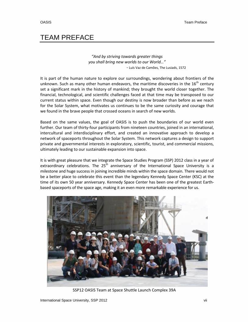
SSP12 OASIS Team at Space Shuttle Launch Complex 39A

OASIS Table of Contents
viii International Space University, SSP 2012
TABLE OF CONTENTS
ACKNOWLEDGEMENTS ............................................................................................................. III
AUTHORS ..................................................................................................................................... IV
ABSTRACT .................................................................................................................................... V
FACULTY PREFACE ................................................................................................................... VI
TEAM PREFACE ......................................................................................................................... VII
INDEX OF FIGURES .................................................................................................................... XI
INDEX OF TABLES ..................................................................................................................... XII
LIST OF ACRONYMS ................................................................................................................. XIII
1 INTRODUCTION .................................................................................................................... 1
2 VISION ................................................................................................................................... 3
3 SPACEPORT MARKET: LEVERAGING EXISTING CAPABILITIES TO DEVELOP NEW
MARKETS ...................................................................................................................................... 5
3.1 EXISTING SPACEPORTS FACILITIES ............................................................................................ 5
3.2 KENNEDY SPACE CENTER – NEW VALUE PROPOSITION AND OPPORTUNITIES .................................. 8
3.3 CURRENT LAUNCHING CAPABILITIES AND PRICE ......................................................................... 9
3.4 MARKET ANALYSIS OF POTENTIAL NEW SERVICES ...................................................................... 9
3.4.1 List of Potential New Services ......................................................................................... 10
3.4.2 Priority Short-Term Services (2012–25) ......................................................................... 11
3.4.2.1 Tug Service from LEO to GEO ......................................................................................... 12
3.4.2.2 LEO On-Orbit Fueling ...................................................................................................... 17
3.4.2.3 GEO On-Orbit Servicing .................................................................................................. 18
3.4.2.4 Warm Back-up Services for GEO Satellites ..................................................................... 19
3.4.2.5 LEO Space Debris ............................................................................................................ 20
3.4.2.6 ISS Decommissioning ...................................................................................................... 21
3.4.3 Priority Medium-Term Services (2025–45) ..................................................................... 21
3.4.3.1 Tug Service from LEO to GEO, Moon Orbit and Back ..................................................... 22
3.4.4 Priority Long-Term Services (2045-Onwards) ................................................................. 23 3.5 ISSUES RELATED TO LAW, POLICY, AND SOCIETY ....................................................................... 25
4 SPACE ENVIRONMENT, RESOURCES AND LIFE SUPPORT SYSTEMS (LSS)............ 26
4.1 SPACE ENVIRONMENT ......................................................................................................... 26
4.1.1 Plasma ............................................................................................................................ 26
4.1.2 Microgravity and Partial Gravity ..................................................................................... 26
4.1.3 Radiation ......................................................................................................................... 27
4.1.4 Meteoroids ..................................................................................................................... 27 4.2 IN SITU RESOURCE UTILIZATION (ISRU) ................................................................................. 28
4.2.1 Lunar ISRU ...................................................................................................................... 28
OASIS Table of Contents
International Space University, SSP 2012 ix
4.2.2 Martian ISRU ................................................................................................................... 31
4.2.3 Phobos and Deimos ........................................................................................................ 33
4.2.4 The Asteroid Belt............................................................................................................. 34 4.3 LIFE SUPPORT SYSTEMS (LSS) AND MEDICINE ......................................................................... 35
4.4 CONCLUSION ..................................................................................................................... 36
5 THE SPACEPORT NETWORK ........................................................................................... 37
5.1 REQUIREMENTS .................................................................................................................. 37
5.2 FUNCTIONAL AND CAPABILITY ANALYSIS ................................................................................. 38
5.3 ARCHITECTURE ................................................................................................................... 39
5.3.1 Approach ......................................................................................................................... 39 5.4 EXISTENCE PROOF .............................................................................................................. 41
5.4.1 Justification ..................................................................................................................... 43
5.4.2 Node Description ............................................................................................................ 46
5.4.3 Network Elements and Standards................................................................................... 47
5.4.4 Verification ...................................................................................................................... 50
5.4.5 Roadmap ......................................................................................................................... 50 5.5 SUMMARY AND CONCLUSION ............................................................................................... 53
6 LAW, POLICY, AND SOCIETY ........................................................................................... 54
6.1 INTRODUCTION .................................................................................................................. 54
6.2 OASIS PROJECT POLITICAL STEPS .......................................................................................... 54
6.2.1 ISECG as a Starting Point ................................................................................................. 54
6.2.2 The International Cooperation ....................................................................................... 54 6.3 THE OASIS MODEL ............................................................................................................ 55
6.3.1 Scope of Political and Legal Entity .................................................................................. 55
6.3.2 The Governing Authority................................................................................................. 56
6.3.3 The Agreements .............................................................................................................. 57 6.4 SECURING THE PROJECT FROM A LEGAL PERSPECTIVE ............................................................... 59
6.4.1 General Legal Framework ............................................................................................... 59
6.4.2 Implications of Servicing Military Satellites .................................................................... 60
6.4.3 Principle of Freedom of Exploration and Use ................................................................. 61
6.4.4 Export Control Implications ............................................................................................ 61
6.4.5 Additional Legal Implications that May Occur ................................................................ 61
6.4.6 Planetary Protection ....................................................................................................... 62
6.4.7 The Principles of “Province of Mankind” and “Non-Appropriation” in Relation to Use of In
Situ Resources .............................................................................................................................. 62
6.4.8 Non-Interference ............................................................................................................ 63 6.5 SOCIETAL IMPACTS.............................................................................................................. 64
6.5.1 International Cooperation .............................................................................................. 64
6.5.2 Awareness ....................................................................................................................... 64
6.5.3 Ethics and Religion .......................................................................................................... 65
6.5.4 Benefits ........................................................................................................................... 66 6.6 CONCLUSION ..................................................................................................................... 67
7 NODE DESIGN STUDIES.................................................................................................... 68

OASIS Table of Contents
x International Space University, SSP 2012
7.1 INTRODUCTION .................................................................................................................. 68
7.2 RATIONALES FOR SPACEPORT NODE 1 .................................................................................... 68
7.3 CONCEPT FOR SPACEPORT NODE 1 ........................................................................................ 68
7.3.1 The Tug ........................................................................................................................... 69
7.3.2 The Depot ....................................................................................................................... 69
7.3.3 Initial Concept of Operations .......................................................................................... 70
7.3.4 Use Cases for Spaceport Node 1..................................................................................... 70
7.3.5 Additional Capabilities .................................................................................................... 71 7.4 SPACEPORT NODE 1 REQUIREMENTS ANALYSIS ....................................................................... 72
7.4.1 Spaceport Top Level Requirements ................................................................................ 72 7.5 SPACEPORT NODE 2 – MOON SURFACE ................................................................................. 75
7.6 SUMMARY AND CONCLUSION ............................................................................................... 77
8 MISSION STUDY ................................................................................................................. 78
8.1 OPTIONS ANALYSIS FOR MISSION TO GTO .............................................................................. 78
8.1.1 Baseline – Launch to GTO, Transfer to GEO ................................................................... 78
8.1.2 Alternative Scenarios Using Spaceports ......................................................................... 79
8.1.3 Discussion ....................................................................................................................... 83 8.2 MISSION TO MARS ............................................................................................................. 83
9 CONCLUSION ..................................................................................................................... 86
10 REFERENCES ................................................................................................................. 88
11 APPENDIX ....................................................................................................................... 99
11.1 SPACEPORT MARKET: BENCHMARK OF SELECTED MAJOR WORLDWIDE SPACEPORTS ............. 100
11.2 POLICY, LAW, AND SOCIETY .......................................................................................... 102
11.3 TUG .......................................................................................................................... 103
11.4 SPACEPORT ................................................................................................................ 104

OASIS Index of Figures
International Space University, SSP 2012 xi
INDEX OF FIGURES
Figure 3-1: Selected Major Worldwide Spaceports ....................................................................... 6
Figure 3-2: Launched Mass to GEO by Launcher Family (Telecoms only) ................................... 13
Figure 3-3: Cost per Kilogram vs. Mass Tugged from LEO to GEO ............................................... 15
Figure 3-4: Flexible Pricing Method and Competition Prices ...................................................... 16
Figure 3-5: Medium-Term Spaceport Network Architecture ...................................................... 22
Figure 3-6: Evolution of the Cost of Lunar Propellant in LEO – Payback Period: 15 years .......... 23
Figure 4-1: Indication of Hydrogen at the Lunar Poles [ISU Team Project, 2007] ....................... 30
Figure 4-2: Nadir NIR Spectral Identifications in Sorted Spectra [Gibson and Pillinger, 2010] ... 30
Figure 4-3: Permanently Lit Region of the Moon [McKee, 2005] ................................................ 31
Figure 4-4: Data from 2001 Mars Odyssey Gamma Ray Spectrometer [NASA, n.d.] .................. 33
Figure 4-5: Hypothetical Ceres' Strata [Pullen, 2009] .................................................................. 35
Figure 5-1: Network Concept Overview Map .............................................................................. 40
Figure 5-2: OASIS Network Overview .......................................................................................... 42
Figure 5-3: OASIS Network Metro Map Analogy ......................................................................... 43
Figure 5-4: Decision Tree for the Network Existence Proof Approach ........................................ 44
Figure 5-5: Roadmap for the Proposed Network Architecture ................................................... 52
Figure 7-1: Spaceport Node 1 ...................................................................................................... 69
Figure 7-2: Upgraded Spaceport Node 1 ..................................................................................... 77
Figure 8-1: Bat Chart of a Mission with Water Supply from Earth. ............................................. 79
Figure 8-2: Bat Chart of a Mission with Water Supply from the Moon. ...................................... 81
Figure 8-3: Schematic of Example Mars Mission ......................................................................... 85
Figure 9-1: OASIS Spaceport Network Concept ........................................................................... 87
Figure 11-1: Diagram of the Model Structure............................................................................ 103

OASIS Index of Tables
xii International Space University, SSP 2012
INDEX OF TABLES
Table 3-1: Launch Vehicle Capability and Price ............................................................................. 9
Table 3-2: List of Potential Services for Short-Term (2012–25) ................................................... 10
Table 3-3: List of Potential Services for Medium-Term (2025–45) .............................................. 11
Table 3-4: List of Potential Services for Long-Term (2045–Onwards) ......................................... 11
Table 3-5: Number of GEO Spacecraft Launched by Mass Category ........................................... 12
Table 3-6: Price per Kilogram Charged to Customers by Existing Launchers .............................. 14
Table 3-7: Market Risks and Mitigation Strategy ......................................................................... 17
Table 3-8: List of Major and Scheduled Space Agencies Planetary Missions .............................. 18
Table 3-9: Annual Number of GEO Servicing Opportunities ........................................................ 19
Table 3-10: Potential Moon Installation Related Services in the Medium-Term (2025–45) ....... 24
Table 4-1: Lunar Surface Average Regolith Composition ............................................................ 28
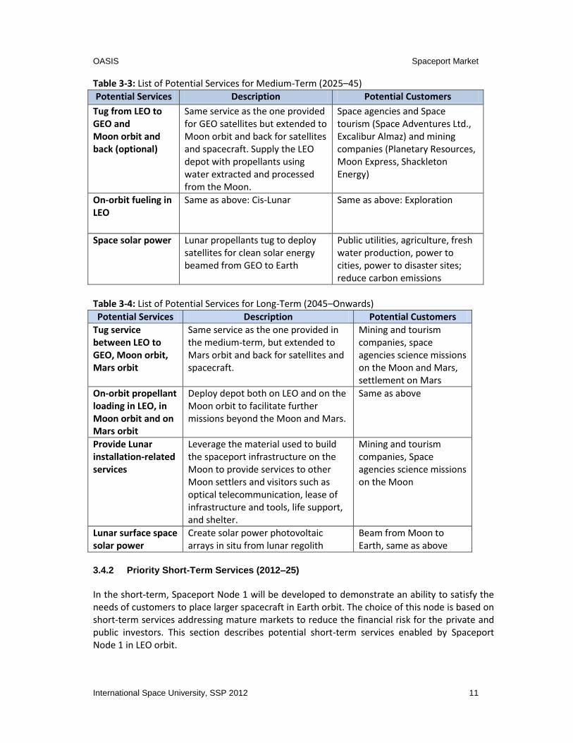
Table 4-2: ISRU Processes for Oxygen Extraction from Regolith ................................................. 29
Table 4-3: Summary of Mars ISRU Requirements ........................................................................ 32
Table 4-4: Science Summary ........................................................................................................ 36
Table 5-1: Top-Level (TL) Technical Requirements ...................................................................... 37
Table 5-2: System-Level (SL) Technical Requirements ................................................................. 37
Table 5-3: Capability and Requirements Matrix .......................................................................... 38
Table 5-4: Propellant Mass Comparison for Different Staging Points ......................................... 46
Table 5-5: Capabilities versus Elements ....................................................................................... 50
Table 5-6: Overview of the Relevant NASA Technology Areas (TA) ............................................ 51
Table 5-7: Overview of Critical Technologies by Phase ............................................................... 53
Table 7-1: Tug Major Components .............................................................................................. 74
Table 7-2: Mass Budget and Power Balance for the Depot ......................................................... 75
Table 7-3: Mass and Cost Breakdown of Spaceport Node 2 ........................................................ 76
Table 7-4: Launch and Investment Cost Overview (2012) ........................................................... 76
Table 7-5: Overview of Cost and Investment Range for Spaceport Node 2 ................................ 76
Table 11-1: Analysis of Legal Entity Options to Create, Manage, and Commercialize the OASIS
Project ................................................................................................................................ 102
Table 11-2: Legal Issues Covering OASIS Activities. ................................................................... 102
Table 11-3: Mass Budget for the Depot ..................................................................................... 104
OASIS List of Acronyms
International Space University, SSP 2012 xiii
LIST OF ACRONYMS
A
AR&C Autonomous Rendezvous and Capture (including Grapple, Berthing,
and Docking)
ASTRA Asteroid Mining Technologies Roadmap and Applications
ATV Autonomous Transfer Vehicle
B
BOL Beginning of Life
C
C1 Caravan1
CARR Concept, Architecture, Roadmap, and Requirements
CHM Common Heritage of Mankind
COSPAR Committee for Space Research
COTS Commercial Orbital Transportation Services
CPT Cryogenic Propellant Tank
D
DESACMI Define, Establish, Synthesize, Analyze, Compare, Make a decision,
Implement
DSN Deep Space Network
E
ECLSS Environmental Control and Life Support System
EDL Entry, Descent and Landing
EML1 Earth-Moon Lagrange point 1
EML2 Earth-Moon Lagrange point 2
EOL End of Life
ESA European Space Agency
EUMETSAT European Organization for the Exploration of Meteorological
Satellites
EVA Extra-Vehicular Activity
F
FAA Federal Aviation Administration
FIT Florida Institute of Technology
FY Fiscal Year
G
GEO Geostationary Earth Orbit
GE Global Exploration Roadmap
GPS Global Positioning System
GSO Geosynchronous Orbit
GTO Geostationary Transfer Orbit
H
HEO High Earth Orbit

OASIS List of Acronyms
xiv International Space University, SSP 2012
IADC Inter-Agency Space Debris Cooperation Committee
IDSS International Docking Standard System
IGA Intergovernmental Agreement
ISBA International Seabed Authority
ISECG International Space Exploration Coordination Group
ISPA International Spaceports Authority
ISRU In Situ Resource Utilization
ISS International Space Station
ISU International Space University
IT Information Technology
ITAR International Traffic in Arms Regulations
ITU International Telecommunication Union
J
JPL Jet Propulsion Laboratory
K
KSC Kennedy Space Center
L
L1 Lagrange point 1
L2 Lagrange point 2
LCROSS Lunar Crater Observation and Sensing Satellite
LEO Low Earth Orbit
LJO Low Jupiter Orbit
LLO Low Lunar Orbit
LMO Low Mars Orbit
LOI Letter of Intent
LRO Lunar Reconnaissance Orbiter
LSS Life Support System
M
MEO Medium Earth Orbit
MLP Mobile Launch Platform
MMOD Micro Meteoroid Orbital Debris
MOE Molten Oxide Electrolysis
MoU Memorandum of Understanding
MPO Mars Polar Orbit
MRG Mobile Resources Gatherer
MSS Moon Surface
MTO Mars Transfer Orbit
MWT Mobile Water Tank
N
NAFCOM NASA/Air Force Cost Model
NASA National Aeronautics and Space Administration
NEA Near-Earth Asteroid
NIR Near Infrared
NGSS NEXT Generation Space Station

OASIS List of Acronyms
International Space University, SSP 2012 xv
NM Notional Mission
NMA Near-Mars Asteroid
NOAA National Oceanic and Atmospheric Administration
NRC National Research Council
O
OASIS Operations And Service Infrastructure for Space
OOS On-Orbit Servicing
OP Orbital Platform
ORU Orbital Replacement Unit
OST Outer Space Treaty
P
PPP Public-Private Partnerships
R
RF Radio Frequency
S
SE Systems Engineering
SEL2 Sun-Earth Lagrange point 2 (on Sun-Earth line beyond the Earth)
SL System-Level
SLS Space Launch System
SMART-1 Small Missions for Advanced Research in Technology 1
SPC Spaceport Company
SSCO Satellite Servicing Capabilities Office (SSCO)
SSP Space Studies Program
ST System-Level
STEM Science Technology Engineering Mathematics
SWT Small Water Tank
T TA Technology Area
TL Top-Level
TMI Trans-Mars Injection
TP Team Project
TRL Technology Readiness Level
U UN United Nations
UNCLOS United Nations Convention on the Law of the Sea
UNCOPUOS United Nations Committee on the Peaceful Uses of Outer Space
US United States
USA United States of America
USD United State Dollars
USSR Union of Soviet Socialist Republics
V
VAB Vehicle Assembly Building
VTVL Vertical Takeoff Vertical Landing

OASIS List of Acronyms
xvi International Space University, SSP 2012
W WBS Work Breakdown Structure
WMO World Meteorological Organization
WP Work Package

OASIS Introduction
International Space University, SSP 2012 1
1 INTRODUCTION
An oasis is a fertile area in a desert, where there is water. Oases are typically located at
waypoints vastly separated between destinations to facilitate travel and commerce. Nomads
and travelers stop at these places to restock food and water, rest, repair broken parts on their
equipment or, if available, obtain new parts and supplies. Like oases in the desert, the
organization of spaceports presented in this report outlines a pioneering, multi-purpose
logistics network of safe havens, enabling human and robotic expansion into the hostile space
environment. A spaceport is an infrastructure waypoint that provides services for space
vehicles and facilitates their departure and arrival.
Operations And Service Infrastructure for Space (OASIS) aims to progressively develop a
network of spaceports (oases) providing support for space exploration and commercial
activities and eventually to expand humanity into space. The International Space Exploration
Coordination Group (ISECG), comprised of fourteen space agencies interested in peaceful
exploration, created a Global Exploration Strategy that provides OASIS with an excellent
opportunity to promote its vision under the framework of international cooperation and
public-private partnership. According to the ISECG Global Exploration Roadmap (GER), the goal
in human exploration of the Solar System is Mars. The majority of these studies envision two
scenarios to reach this destination, by considering going to either the Moon first or to an
asteroid first (ISECG, 2011).
Getting to and living on these exciting destinations poses some significant challenges. Current
launch systems, while very capable, are unable to provide sufficient mass to orbit at an
acceptable cost. Current launch systems often place a spacecraft as well as five to ten tons of
propellant into orbit. This propellant boosts the spacecraft to its desired destination but
consumes much of the launch system’s volume and energy. The OASIS team proposes to
change this model by placing the propellant and other support items in a convenient location in
space (a spaceport), allowing current launch systems to lift more spacecraft mass into Low
Earth Orbit (LEO).
Placing the propellant in LEO for orbit transfer from Earth orbit to other orbits facilitates
government space exploration and more affordable commercial use of space. The addition of
life-support consumables and support services in Low Earth Orbit would constitute a full-
service spaceport. A spaceport in LEO would enable more affordable tourism, space-based
telecommunications, energy, and debris removal. Once spaceports prove to be effective in LEO,
the OASIS team proposes the creation of a network of spaceports that may include locations on
the Moon, Mars and asteroids to further enable space exploration.
All space-faring nations and corporate entities will be very interested in this change so OASIS
anticipates significant political, legal and social debate regarding the spaceport network. After
examining global success with public-private partnerships, OASIS proposes the creation of a
new inter-governmental organization to support the development of the spaceport network. In
addition, the OASIS team describes a new treaty and explores options to deal with specific

OASIS Introduction
2 International Space University, SSP 2012
political, legal, societal and ethical considerations.
OASIS follows a phased approach to the design, development and operation of the spaceport:
a. Assess existing and planned capabilities of terrestrial spaceports;
b. Identify spaceport functions, capabilities and services necessary for several
connections, or waypoints, of a spaceport network;
c. Select appropriate spaceport nodes that meet government space exploration and
commercial development needs; and
d. Prescribe a possible sequence of spaceport node development based on market needs,
risk profile and sound business practice.
Each spaceport node relies on the quantity and setting of local resources, which the network
can leverage within the design. This report presents an overview of the methods of extracting
these resources and the difficulties imposed by the space environment. The near-term
identifies the main products supplied to space missions by in situ resources will mainly be
propellants and life support consumables; as such these areas form the focus of the discussion.
The spaceport network solution will be designed after completing the market and feasibility
analyses. The requirements, functions and architecture of the spaceport network determine
the basis for the roadmap of the important steps and time phasing of this spaceport network.
Legal and political aspects determine the impact of such a network on Earth. Key issues include
registration, ownership and free access issues. This work examines the issues on liability as well
as the use of resources in a legally-, politically-, and culturally-acceptable manner as well as the
cultural and social topics of long-term missions.
The OASIS team investigated a conceptual design of a spaceport node in LEO alongside the
different services it provides, such as repair, orbit slot change, de-orbit, and salvage. This
proves that there is at least one capable option and constitutes an “existence proof”. Such a
node can also offer services such as storage, idling, warm backup, a solution for space debris,
and potentially decommissioning of space structures.
An example mission study, provided by the OASIS team, of tugging a satellite into
Geostationary Earth Orbit (GEO) from LEO presents a continuation of the “existence proof”.
This, coupled with a cost study of launching a satellite directly from the Earth to GEO, serves as
a baseline for the mission justification. Comparisons are made on the source of propellant,
whether it is provided from the Earth or the Moon.
One of the big challenges of the 21st century is to lower the cost of access to space and the
OASIS team is accepting the challenge by describing a revolutionary vision of approaching
space travel.
OASIS Vision
International Space University, SSP 2012 3
2 VISION
“...we are not simply reaching out into space to use extraterrestrial resources and create opportunities here on Earth. Rather we are laying the foundations for a series of new civilizations that are the next logical step in the evolution of human society”
Frank White “The Overview Effect” Humans are curious explorers by nature. They strive to reach new heights and expand their horizons. When we think about space, about the Universe, it becomes even more literal. Our need for adventure, for planting seeds of humanity throughout other worlds pushes us to break our assumed limits and reach higher. In the age of technology, when more and more is possible, it is time to break the chains of our Mother Earth and create our new home, the Universe. The history of mankind has proven on numerous occasions that with a great goal in mind it is always a step-by-step process that leads to tremendous results. Ancient Romans proved that when they proceeded to build roads of the Roman Empire. Knowing that efficient travel and trading required reliable paths with safe oases for rest and for supply transfer, led the Romans to develop the greatest road system of the ancient world, a precursor of all of the current routes of Europe. Later generations of Europeans, fully aware of economical and societal advantages of trade between diverse nations and lands, made an enormous effort to create new routes with safe ports on the way to enable spice trading. Now is the time to establish routes to the stars with safe ports in space, spaceports, marking the most important stops on our way through the Solar System and beyond. Reaching Earth orbit, or the Moon, or even Mars is not an ultimate goal. These locations are just waypoints in the venture of humans. On Earth, connecting new frontiers back to already existing civilized areas through a logistics network always led to their development. The end goal of the OASIS concept is to provide the basis for an ever-growing and evolving multipurpose logistics network facilitating access to all corners of space. For the logistical benefits above, as well as the potential for economic and political benefits, OASIS proposes a network of spaceports and associated routes, working within the context of the International Space Exploration Coordination Group’s (ISECG) Global Exploration Roadmap (GER). As with every project, building upon existing foundations is crucial. Therefore, the concept starts here, on Earth, with existing terrestrial spaceports and the first route to an outpost close to Earth, LEO, and then progresses further into the Solar System. Even though there are already ways to travel to LEO, there is no stop-over safe haven, no port to refuel or provide required services, nor a midway location to launch and stage, and an OASIS spaceport provides these enabling functions. To date, only the Saturn V rocket has had enough capacity for the missions sending humans to the Moon and return. With the network of spaceports proposed through the OASIS concept, launch providers can accomplish similar missions with smaller, less expensive rockets like Falcon 9, Atlas V or Delta IV, ultimately reducing costs. Reducing the per-mission cost will

OASIS Vision
4 International Space University, SSP 2012
create a friendlier environment for startup commercial vehicle providers and cause better, reduced launch prices for users due to increased competition. The ability to go to the Moon with a moderately-sized rocket could trigger nations other than existing space-faring states to start a space program. Alternatively, nations with heavy lift launchers can use them to lift significantly more mass per launch into orbit, therefore avoiding on-orbit assembly. The first step beyond Earth is Spaceport Node 1 of the space transportation network. This node has a primary purpose of allowing more inexpensive and easier ways of providing space transportation beyond LEO. Once the first spaceport is located, this staging point outside of Earth’s gravity well, is established; then the network can be expanded to other nodes and locations, like the Moon, around Mars, or even further into the Solar System. Once the proposed network of spaceports is established, humanity would witness the dawn of a new, inspiring era in which humans are able to live on the Moon and further into the Solar System. The network of spaceports will enable a whole new market of lunar tourism, solar space energy, and beyond. Each of the potential spaceport node locations offers a different set of resources and services. Each node is unique, and as the network grows, each node will serve its own, important purpose. For example, the Moon can be mined and the resources used to provide propellants and life support to customers that want to travel within the Solar System. The unique capabilities and relative safety of a spaceport in LEO (within the Earth’s magnetosphere which protects from space radiation) can help transfer spaceships to higher orbits. Spaceports in Mars orbit or on the Mars moons could enable Mars surface exploration and a permanent human presence. The history of mankind is full of examples of countries that thrived as they established new communities. There were always risks and struggles with taking these first steps into unknown territory. The OASIS team believes that creating outposts in the Solar System will provide financial benefits and increased prestige for any nation involved in the project. Spaceports are just an overture to a future we, as humans, will create outside of our home planet. The goal of the OASIS team is to create a financially, legally and technically feasible concept for building a spaceport network. The vision is to create a doorway, a path for humanity to the worlds outside of our own, to places not yet accessible, to places humans have only dreamt about. This document details a practical, phased approach to the development of a spaceport network based on fundamentals in physics, engineering, business, policy and law. Practical solutions are proposed, basic calculations undertaken, and business analysis and legal proposals are evaluated. This OASIS report makes a push for the ultimate goal, the great vision that will motivate and push nations and individuals towards the creation and maintaining of spaceports network. There is a universe of opportunities awaiting us beyond our home planet. There are worlds to be discovered, resources to be discovered and used, as well as new experiences for humans. As astronaut Eileen Collins said: “We want to explore. We're curious people. Look back over history, people have put their lives at stake to go out and explore ... We believe in what we're doing. Now it's time to go” (Space.com, 2005).

OASIS Spaceport Market
International Space University, SSP 2012 5
3 SPACEPORT MARKET: LEVERAGING EXISTING CAPABILITIES TO DEVELOP NEW MARKETS
A spaceport network will use existing terrestrial spaceport facilities to provide launch services to transport necessary resources from Earth’s surface to space. The selection of spaceport facilities offering the most suited inclinations with low-cost, reliable and high mass to orbit launch vehicles will reduce the initial development cost. By considering, during the network architecture design phase, the services provided by the spaceport network in the short-, medium-, and long-term, the development and operational cost will be optimized. The operational viability of the spaceport network is highly dependent on whether or not the network is making a profit and therefore can build on its profits to upgrade its infrastructure and expand to other locations in Space. Sufficient revenue from services offered must be generated to cover the operational cost and recover the initial investment after some years. To address these requirements, Chapter 3 establishes the state-of-the-art terrestrial launching capability and identifies the potential new markets in the short- to long-term addressable by the spaceport network. A review of the top-priority markets where the spaceport expects to generate a significant amount of revenue is explained. Then, high-priority revenue-producing markets are identified.
3.1 Existing Spaceports Facilities
OASIS introduces a transportation network intended to extend the existing infrastructure on Earth into Space. To understand this novel approach, it is important to first understand the existing terrestrial nodes of the future network. Therefore, this section provides an overview of terrestrial spaceports, their locations and functions. A section dedicated to Kennedy Space Center is provided as an example of a terrestrial spaceport, and the discussion focus is on its new potential value proposition and future opportunities. The number of spaceports worldwide is steadily growing. Some of these spaceports, like Kennedy Space Center and Baikonur Cosmodrome, have supported spaceflight for more than 50 years. Others, like Spaceport America, have yet to accomplish the launch of a first spacecraft. The OASIS team selected a number of spaceports for this study. As a selection criterion, the OASIS team chose the spaceports with services similar to Kennedy Space Center. This approach implies that this report does not include those spaceports that are limited to suborbital launches. Figure 3-1 shows the location of the selected spaceports around the world. In alphabetical order, those spaceports are: Baikonur Cosmodrome (Kazakhstan), Cape Canaveral Air Force Station (USA), Jiuquan Satellite Launch Center (China), Kennedy Space Center (USA), Kourou /Guiana Space Center (French Guiana), Mid-Atlantic Regional Spaceport (USA), Sea

OASIS Spaceport Market
6 International Space University, SSP 2012
Launch/Odyssey Launch Platform (USA based), SHAR Sathish Dhawan Space Center (India), Taiyuan Satellite Launch Center (China), Tanegashima Space Center (Japan), Vandenberg Air Force Base (USA) and Xichang Satellite Launch Center (China).
Figure 3-1: Selected Major Worldwide Spaceports
The study briefly presented some of the selected evaluation criteria for their specific importance. For example, the location of a spaceport is critical for latitude and range. Low latitude means that the spaceport’s location is close to the equator. This is desirable for the launch of geosynchronous and geostationary satellites. As these GEO satellites’ positions are near a zero-inclination orbit, a launch from higher latitudes requires a plane-change maneuver. This maneuver requires a certain mass of propellant, which needs to be subtracted from the payload mass. Additionally, the rotation of the Earth at lower latitudes results in a higher absolute velocity of the spacecraft at launch when launched to the East, reducing the total change in velocity required to attain orbit. In conclusion, proximity to the equator results in higher payload mass to GEO. Some examples of favorably located spaceports are listed below.
To date, all launched spacecraft from the Odyssey Launch Platform, operated by Sea Launch, have been destined for GEO. The self-powered, floating platform moves to the equator in the Pacific Ocean, prior to launch.
The Guiana Launch Center in Kourou, French Guiana, with the latitude of 5° N, is one of the closest spaceports to the equator.
In contrast, a high latitude spaceport is desirable for the launch of polar orbiting spacecraft. Examples of these spacecraft are sun-synchronous Earth observation satellites.

OASIS Spaceport Market
International Space University, SSP 2012 7
The majority of the worldwide spaceports’ locations are between these two latitudes. Therefore, the 16 national partners who participate in the International Space Station (ISS) program constructed and operate the ISS with an orbit inclination of 51.6°. The two main spaceports that support ISS launch-related construction and operations are Kennedy Space Center (latitude 28.5° N) and Baikonur Cosmodrome (latitude 46° N). The range is important for a spaceport because the operation of launch vehicles always poses a risk to the population around the launch site. The United States Federal Aviation Administration (FAA), an example of a regulatory agency, evaluates the risk for each proposed launch corridor before issuing a license to a new spaceport. As it is favorable to launch spacecraft eastwards with the rotation of the Earth, the risk could be minimized, if a spaceport’s location is on an east coast and consequently could launch eastwards over an ocean. Examples of spaceports with desirable locations are, for the U.S., Kennedy Space Center, the Japanese spaceports of Uchinoura and Tanegashima, and Europe’s Guiana Launch Center. An example of a less favorable location for a spaceport is the Baikonur Cosmodrome. It is politically undesirable to directly launch eastwards due to launching Russian vehicles over Chinese territory. Even though the area around Baikonur is not densely populated, spent rocket stages pose a danger to the population as well as the environment. The services provided by the evaluated spaceports worldwide are similar because this study covers only the spaceports comparable to Kennedy Space Center. Spaceports provide launch infrastructure for different vehicles, from suborbital sounding rockets to heavy orbital launch vehicles. A recently observed trend is the growth of spaceports offering a launch infrastructure for reusable vehicles, for example, runways for suborbital vehicles with a horizontal takeoff and landing, and vertical takeoff with recoverable boosters. Spaceports also offer facilities to store and handle propellants, including cryogenics, hypergols, solid propellants, associated purge gases and other consumables. Some spaceports also offer propellant production facilities. The Guiana Space Center offers onsite cryogenic propellant fuel production as well as facilities for the manufacturing of solid rocket boosters. Spaceports also have spacecraft integration and testing facilities, often including clean rooms. Most of the spaceports provide range control, telemetry, tracking capabilities and mission control centers. All the above mentioned services indicate that it is also advantageous to offer accommodation and cafeterias for personnel operating these facilities, as well as perimeter control and security services to ensure absolute safety for flight hardware and personnel. Another important evaluation consideration is the logistics to and from a spaceport. Runways are essential because satellites are mainly transported to the launch site by airplane. Railroads and seaport access are necessary for the transport of rocket stages. Roadways to major industrial and urban areas are required for personnel access. For example, Kennedy Space Center on Florida’s Space Coast is much easier to access than the Guiana Space Center because of its remote location surrounded by the jungle of French Guiana. Spaceports must not be regarded as single entities; they should be considered collectively as individual nodes in an existing transportation network on Earth. Some current studies envision suborbital point-to-point travel between spaceports on Earth. OASIS is going one step further. The OASIS team is proposing to extend the terrestrial spaceport network into space to facilitate

OASIS Spaceport Market
8 International Space University, SSP 2012
transportation to nodes in orbit and on other celestial bodies. The commonality among nodes is that spaceport nodes are simply waypoints to other destinations: a service infrastructure for space travel by explorers, scientists, entrepreneurs and other customers. To survive and thrive in a competitive environment, spaceport providers must understand the needs, goals and constraints of their customers. A benchmarking matrix with the list of functions and capabilities provided by existing different spaceports is contained in Appendix 11.1. The next section focuses on Kennedy Space Center as one example of a spaceport and evaluates future opportunities for its development.
3.2 Kennedy Space Center – New Value Proposition and Opportunities
During the Space Studies Program 2012, the OASIS team had the unique opportunity to visit Kennedy Space Center and to learn about the center’s history as well as the center’s current developments. With the end of the Space Shuttle Program, KSC is now in a transition and is expected to phase to new ways of doing business with both government operations of the Space Launch System (SLS), and crew capsule, Orion, and commercial launch vehicle operations at Launch Complex 39. Kennedy Space Center is addressing the challenges of these concurrent activities. For example, KSC is preparing one of the Vehicle Assembly Building (VAB) high bays, Mobile Launch Platforms (MLPs), and the Launch Pad to be able to integrate, process, and launch different vehicles. These changes lead to other operational challenges. Commercial customers may request restricted access to protect their proprietary assets, yet they may be working in the vicinity of their competition. KSC needs to reduce the bureaucratic effort for commercial entities to use government assets. These ventures will take a higher risk than the National Aeronautics and Space Administration (NASA). “Failure is not an option” (Broyles, 1991) is the approach for government led human spaceflight, but the application of the same regulations with commercial spaceflight can lead to competitive disadvantages on the open market. In return, government operations may benefit from newer, leaner ways of doing business learned from the commercial operators. One of the factors that will determine KSC’s success in the future is the reduction of operational cost. For total launch costs, facility costs and the spaceport’s range cost contribute to the cost of the launch vehicle. To stay financially attractive in a worldwide market, these costs need to be reduced. To lower personnel costs, this new paradigm of commercial launch operations will drive a model where the workforce associated with launch campaigns at KSC fluctuates with the market rather than holds steady at a base level to support all operations at once. Looking beyond launch and processing facilities, to further increase KSC’s attractiveness to commercial customers, the OASIS team recommends creating living accommodations and

OASIS Spaceport Market
International Space University, SSP 2012 9
offices in close proximity to the launch infrastructure. The OASIS team also recommends continuing and increasing cooperation with local educational institutions and further development of Exploration Park to foster innovation and reduce costs at KSC.
3.3 Current Launching Capabilities and Price
For many decades, the high cost of launch services has been one of the biggest obstacles to the growth of space commercialization and exploration. A temporary, relatively low price did appear between the years of 2003 and 2006, but from 2007, the price began to increase again and is still very high. The data listed in Table 3-1, as well as Table 3-6, is from the launch vehicle provider’s official website and public release, indicating the current available (or available in 2012–15) major launch vehicles and their respective estimated price (United Launch Alliance, 2011; Space Exploration Technologies Corporation, 2012; China Great Wall Industry Corporation, 2011; Arianespace, 2011; International Launch Services, 2009; Sea Launch, 2008 and JAXA, 2012). Table 3-1: Launch Vehicle Capability and Price
Launch Vehicle Delta IV Heavy
Atlas V Heavy
Falcon Heavy
LM-5 Ariane-5 Proton-M Zenit-3SL LM-3B H2B Falcon 9
GEO (Tons) 6.6 6.5 6.3 5.1 5.0 3.3 2.9 1.8 N/A N/A
GTO (Tons) @ inclination
13.0 @28.5o
13.0 @28.5o
12.0 @27o
14.0 @19.5o
9.5 @6o
6.15 @23.2o
6.1 @0o
5.5 @28.5o
8.0 @28.5o
4.9 @28.5°
LEO (Tons) km@ inclination
22.6 [email protected]
29.4 [email protected]
53.0 [email protected]
25.0 [email protected]
21.0 [email protected]
23.0 [email protected]
7.3 1000@0o
11.5 [email protected]
16.5 [email protected]
13.2 [email protected]°
Price Est. ($m 2012)
200 200 128 150 150 100 100 80 150 54
3.4 Market Analysis of Potential New Services
This section identifies the potential new services that could be offered by the spaceport network in the short-term (2012–25), medium-term (2025–45) and long-term (2045–onwards) terms. The concept and financial attractiveness for customers for each service is described. Market sizing and profitability are explored for short-term core services. The chosen spaceport network will consist of an Earth Node 0, Spaceport Node 1 in LEO developed in the short-term, expanding with Spaceport Node 2 on the Moon’s surface in the medium-term and establishing Spaceport Node 3 on the surface of Phobos, one of Mars’ moons, in the long-term. The rationale for the choice of the nodes will not be fully addressed in this section. Only the business related rationales will be discussed. The architecture section will provide further details on

OASIS Spaceport Market
10 International Space University, SSP 2012
the selection process and the advantages of the overall selected architecture. 3.4.1 List of Potential New Services
Table 3-2: List of Potential Services for Short-Term (2012–25)
Potential Services Description Potential Customers
Tug from LEO to GEO
Use a tug unit to transport a GEO satellite from LEO to GEO. Produce propellants at Spaceport Node 1 by electrolyzing water provided from Earth. Load propellant in tug, rendezvous and connect with the spacecraft and transport to GEO.
Commercial GEO satellite operators (for example, Intelsat)
On-orbit fueling in LEO
Use the water depot and electrolyzer in LEO to provide cryogenic LO2/LH2 fueling services to spacecraft or satellites going beyond LEO.
Space agencies and commercial planetary missions
Space debris mitigation (optional)
Use the tug and the propellant available at the depot to provide deorbiting services of space debris from LEO to Earth’s atmosphere.
Space agencies and governments
Space structure decommission (optional)
Use the tug and a new propellant depot to safely decommission a large on-orbit structure at the “end of life”.
ISS, Bigelow Aerospace, Orbital Technology, Tiangong
On-orbit servicing (optional)
Use a specific spacecraft to provide inspection, relocation, restoration, repair, augmentation and assembly services for existing GEO and LEO satellites.
Satellite operators
Warm back-up (optional)
Provide back-up satellites for GEO satellites operator in case of emergency/failure of one of the satellites and depending on the criticality of the service provided.
Space agencies, insurance companies, and commercial satellites
OASIS Spaceport Market
International Space University, SSP 2012 11
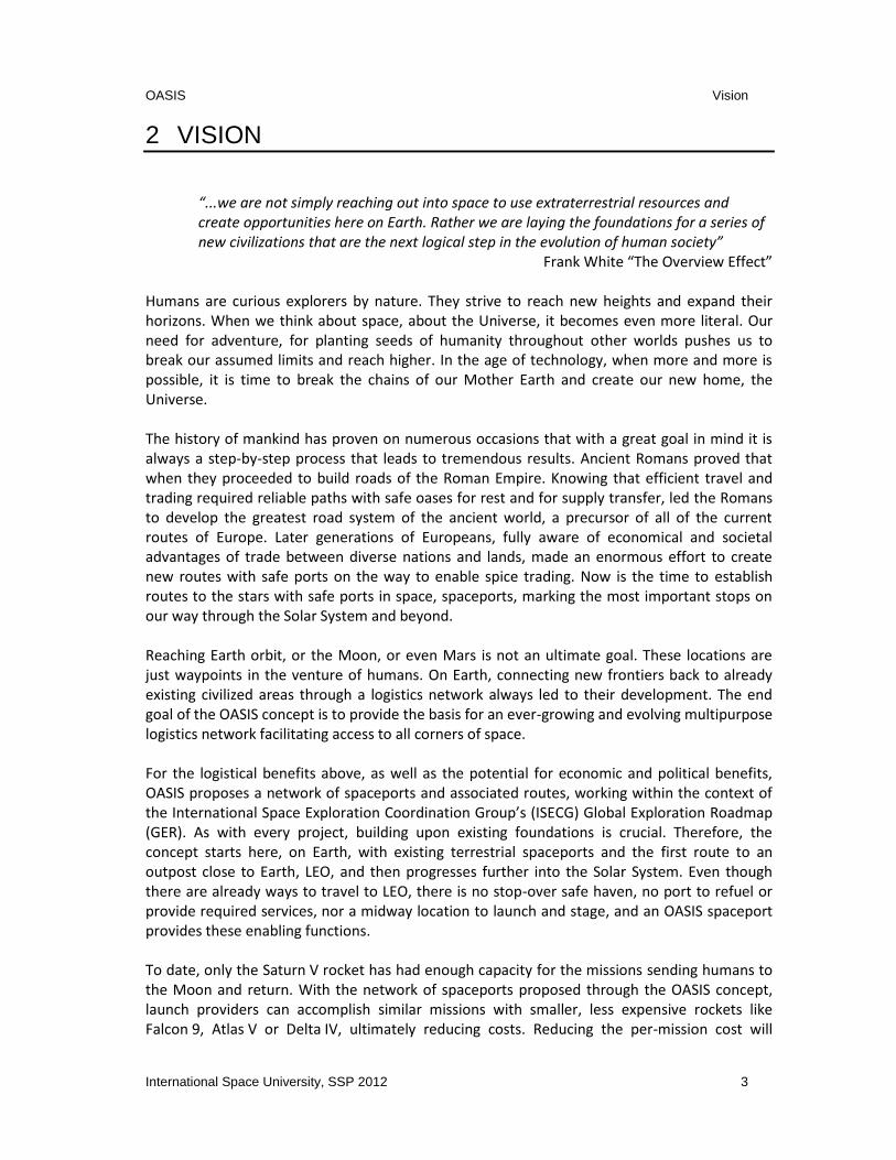
Table 3-3: List of Potential Services for Medium-Term (2025–45)
Potential Services Description Potential Customers
Tug from LEO to GEO and Moon orbit and back (optional)
Same service as the one provided for GEO satellites but extended to Moon orbit and back for satellites and spacecraft. Supply the LEO depot with propellants using water extracted and processed from the Moon.
Space agencies and Space tourism (Space Adventures Ltd., Excalibur Almaz) and mining companies (Planetary Resources, Moon Express, Shackleton Energy)
On-orbit fueling in LEO
Same as above: Cis-Lunar Same as above: Exploration
Space solar power Lunar propellants tug to deploy satellites for clean solar energy beamed from GEO to Earth
Public utilities, agriculture, fresh water production, power to cities, power to disaster sites; reduce carbon emissions
Table 3-4: List of Potential Services for Long-Term (2045–Onwards)
Potential Services Description Potential Customers
Tug service between LEO to GEO, Moon orbit, Mars orbit
Same service as the one provided in the medium-term, but extended to Mars orbit and back for satellites and spacecraft.
Mining and tourism companies, space agencies science missions on the Moon and Mars, settlement on Mars
On-orbit propellant loading in LEO, in Moon orbit and on Mars orbit
Deploy depot both on LEO and on the Moon orbit to facilitate further missions beyond the Moon and Mars.
Same as above
Provide Lunar installation-related services
Leverage the material used to build the spaceport infrastructure on the Moon to provide services to other Moon settlers and visitors such as optical telecommunication, lease of infrastructure and tools, life support, and shelter.
Mining and tourism companies, Space agencies science missions on the Moon
Lunar surface space solar power
Create solar power photovoltaic arrays in situ from lunar regolith
Beam from Moon to Earth, same as above
3.4.2 Priority Short-Term Services (2012–25)
In the short-term, Spaceport Node 1 will be developed to demonstrate an ability to satisfy the needs of customers to place larger spacecraft in Earth orbit. The choice of this node is based on short-term services addressing mature markets to reduce the financial risk for the private and public investors. This section describes potential short-term services enabled by Spaceport Node 1 in LEO orbit.

OASIS Spaceport Market
12 International Space University, SSP 2012
3.4.2.1 Tug Service from LEO to GEO
The geostationary spacecraft represent a mature market that has remained stable over the past 10 years consisting of an average of about 20 spacecraft launched per year with an average mass per satellite of 4.0 tons, per spacecraft. Currently about 400 spacecraft are located in GEO providing mainly telecommunications services but sometimes meteorology, navigation, remote sensing and military-related services. The risk of telecommunication interference limits the number of operational GEO spacecraft. It is expected that the number of spacecraft launched into the GEO orbit will remain between 20-23 satellites per year, reference Table 3-5. However, the average mass per spacecraft is expected to increase as “the trend is to build heavier, more capable satellites”, based on the research conducted by Federal Aviation Administration (2012). In the future, the average mass per GEO spacecraft will reach about 4.5 tons per satellite (ASD-Eurospace, 2012). Table 3-5: Number of GEO Spacecraft Launched by Mass Category
OASIS intends to capture part of this market in the short-term to allow the spaceport network to reduce its financial risk and ensure sufficient revenue to potentially cover the inherent cost of development and operation of Spaceport Node 1. A tug, whose detailed design is in the later sections, that transports spacecraft from LEO to GEO, represents the core service that the spaceport network will provide in the short-term. This service is in direct competition with the upper stages currently provided by launch vehicles servicing the GEO market (ASD-Eurospace, 2012), as seen in Figure 3-2.

OASIS Spaceport Market
International Space University, SSP 2012 13
Figure 3-2: Launched Mass to GEO by Launcher Family (Telecoms only)
The value proposition of this service for spacecraft operators is the ability to place GEO spacecraft in orbit less expensively. For launch vehicle providers, this service will allow current launch vehicles to place larger, more massive spacecraft in orbit to enhance their revenue. The LEO launch mass limit and maximum amount of propellant that the tug can carry will set the new mass limit for GEO spacecraft. An additional benefit of providing such a service is the possibility for smaller size launch vehicles (for example, Soyuz) to enter the GEO market by providing the LEO launch segment. A partnership between the spaceport network and smaller launch vehicle providers may reduce the cost of getting to LEO for the spaceport network in exchange for an increased GEO market for the smaller launch vehicle providers. For heavy mass GEO spacecraft that cannot be accommodated by existing GEO launchers, the spaceport network will be able to charge a premium launch price to GEO. To determine the attractiveness of the service to a GEO spacecraft operator, the cost of providing such a service versus the price currently charged must be known. Spaceport Node 1 in LEO will consist of a water depot, an electrolyzer and a tug, all launched from the surface of Earth. Water launched from Earth will be converted to LO2 and LH2 at the water depot to refuel the tug. When the GEO satellite reaches LEO orbit, the tug separates from the depot and docks to the satellite using the same interface as that used with the launch vehicle. The tug transports the satellite from LEO to either Geostationary Orbit or Geostationary Transfer Orbit (GEO/GTO) using its propellant. Once in GEO/GTO, the tug separates from the satellite and returns to LEO orbit. Existing GEO spacecraft launchers charge the full price of the launcher to the GEO spacecraft operator regardless of the actual mass launched. Considering a Falcon 9 launcher from Earth to GTO, the price of the launch services is $54m for a maximum mass to GTO of 4.85t. If the GEO satellite is 4.85t, the price paid of the satellite is $11,134 per kilogram. On the other hand, if the

OASIS Spaceport Market
14 International Space University, SSP 2012
GEO spacecraft is 4t, the price per kilogram becomes $13,500, an increase of 21%. To offer a competitive price per kilogram for its customers, Ariane maximizes the mass used per launch by offering a dual launch to GTO with a maximum mass of 9.5t. Unfortunately, the number of GEO spacecraft launched per year is limited to 20 satellites. As a result, finding two GEO spacecraft with similar mass, fitting within the Ariane fairing, remains a challenge for Arianespace. The “tug” service provides another possible solution. The “tug” service enables launches of single or dual GEO spacecraft into LEO and allows the remaining volume/mass in the launcher to be filled with either another LEO spacecraft or water to refill the depot at Spaceport Node 1. This ensures a minimum launch cost per kilogram from Earth to LEO for any selected launcher. As a result, the spaceport network will be able to offer lower launch cost to GEO satellite operators and even to LEO spacecraft operators that also cannot always use the maximum mass offered by the selected launcher. As an example of how this process might work, a tug can be designed to transport a 9t payload from LEO to GEO. Currently, the maximum spacecraft mass to GEO is about 6.5t. The tug service presents the additional advantage of being able to send more massive spacecraft to GEO. If we consider that launch operators manage to use the maximum mass to GTO and LEO of their launchers, the price per kilogram is displayed in Table 3-6. OASIS would still provide the lowest price solution for GTO even after considering a 20% profit margin for the spaceport. Falcon Heavy is not considered, as it is not yet operational. The impact of Falcon Heavy on the tug service profitability will be analyzed later. Table 3-6: Price per Kilogram Charged to Customers by Existing Launchers
Considering a dual satellite launch from Earth to LEO and using a low-cost launcher to launch water to refill the LEO depot, the spaceport can reach a lower cost structure than conventional GEO satellite launchers. Insurance cost is reduced: instead of insuring two launches, the

OASIS Spaceport Market
International Space University, SSP 2012 15
satellite operators can insure one launch; the launch with the water does not require insurance (nor any additional safety, analysis or testing charges). The water could be sent as a second payload in LEO launches at a reduced price to reach the maximum mass of the launcher. Note, the tug spacecraft is designed for 9t to GEO, which results in more than 9t of mass to GEO after the circularization maneuver, but only 9t to GTO is considered for the sake of comparing with other launch solutions. The total mass of the dual launch is 9t in GTO, the dry mass of the tug is 2.9t. The required amount of propellant to transport the tug and both satellites from LEO to GTO is 8,730kg. Considering that 1.28kg of water produces 1kg of propellant, the required amount of water is 11,174kg. Considering a cost of launch from Earth to LEO of $4,000/kg (Proton: $4,348/kg; Falcon 9: $4,106/kg) for both satellites, $3,200/kg for the water, and neglecting the cost of purchase and logistics of the water on Earth, the total cost to bring both satellites from Earth to GTO is $71.8m without charges. Considering 10% charges (tug operations and monitoring), the total cost for the OASIS Earth to GTO service is $78.9m or $8,770/kg of GEO satellites. Considering a 20% profit margin, the price charged for both satellites is $98.7m or $10,963/kg of GEO satellites. Figure 3-3 shows the evolution of the cost per kilogram in function of the mass transported by the tug from LEO to GTO.
Figure 3-3: Cost per Kilogram vs. Mass Tugged from LEO to GEO
The cost per kilogram significantly increases for a mass tugged from LEO to GTO lower than 3t. For these masses, the tug is oversized and the extra mass of the tug is transported from LEO to GTO and back to LEO. This increase in cost leads to a negative profit for masses lower than 3t if it is decided to fix the price at $10,963/kg regardless of the mass of the GEO satellite(s). A more adequate solution to avoid reducing profit margins is to adopt a flexible pricing method: regardless of the mass tugged from LEO to GTO, a 20% profit margin on the cost can be charged. Figure 3-4 shows the evolution of the price charged to the customers as a function of the mass

OASIS Spaceport Market
16 International Space University, SSP 2012
tugged from LEO to GTO using the flexible pricing method. It also shows the cost for the GEO satellite customers of using any of the existing GEO launchers. Two areas are highlighted in red and show potential competition from Falcon 9 and Falcon Heavy as they match OASIS prices for certain ranges of mass. One solution is to lower the price by reducing the profit margin for these ranges. However, the OASIS solution would still allow more comparable dry mass to be launched with any chosen launch vehicle.
Figure 3-4: Flexible Pricing Method and Competition Prices
In the short-term, the Spaceport Node 1 “tug” service may only capture four of the 20-23 GEO satellites, with an average mass of 4.5t, launched per year. If two are dual launch and two are single launches, using the flexible pricing method, the yearly profit is $42m. This yearly profit figure does not take into account the potential profit from offering lower launch cost to LEO satellites willing to launch with GEO satellite(s) in one launch (thus reaching the maximum mass of the launcher and ensuring the lowest cost for a given launcher). The estimated initial investment required is $296.3m and will be recovered within 7 years. The initial costs consist of the development, manufacturing and testing of the tug for $241.4m, the electrolyzer for $12m, the solar panels for the electrolyzer for $3m and the launch of the three structures to LEO with a combined weight of 9.7t at a launch cost of $4,106/kg (Falcon 9). The LEO tank (capable of hosting 30t of water) is counted as operational cost. Considering market dynamics and risks, two major risks (Table 3-7) need to be considered. The first risk is a reduction of the GEO satellite launch price to $10,000/kg (retaliation within the existing GEO launchers market) or the development of a new capability such as the Falcon Heavy. In the case of retaliation, for the market of GEO satellites with a higher mass than existing launcher maximum capability (to GEO), the spaceport revenue from the “tug” service is not affected. In all the other cases, the spaceport should reduce the price it charges for the “tug” service reducing its profit margin. In addition, if the price for GEO decreases, this will also decrease the price to LEO leading to a

OASIS Spaceport Market
International Space University, SSP 2012 17
lower cost for the spaceport to refill its water tank in LEO and for the Earth to LEO segment for the GEO satellites. The spaceport offers the “tug” service from LEO to GEO and the LEO launch as one package to GEO satellite operators. Offering a package service from Earth to GEO will bring to the spaceport several benefits:
Possibility to contract with a LEO launch provider for several launches to reduce the unit cost per launch through negotiations
Higher control over the distribution of the GEO satellite business captured by the spaceport, leading to competition among the LEO launchers to offer the lowest price (under market price) in exchange of an exclusive partnership, allowing the LEO launcher to offer a GEO launch capability and receive the LEO segment revenue of the GEO service offered by the spaceport
Possibility to offer multiple launches for GEO satellites but also LEO satellites and to complete the maximum mass with water if needed
Table 3-7: Market Risks and Mitigation Strategy
The second risk is the appearance of GEO refueling and on-orbit servicing in the market. By extending the life of a GEO satellite, these services reduce the market for GEO satellite launches. Assuming that the service doubles the life of a GEO satellite and manages to capture half of the GEO satellite market, this will result in a 25% reduction of the GEO satellite launch market. To mitigate such risk, the spaceport will reduce its price for GEO satellite launch until it is more attractive to launch a new GEO satellite than to extend and upgrade an old one. Another possibility for the spaceport is to provide “tug” services from LEO to GEO for the GEO refueling and on-orbit servicing satellites to compensate for the loss of market. 3.4.2.2 LEO On-Orbit Fueling
Leveraging the existing 30t water tank and the electrolyzer in LEO orbit, the spaceport will be able to offer LEO on-orbit fueling to space agencies or commercial planetary missions. Considering only space agencies, major planetary missions currently scheduled for the next five

OASIS Spaceport Market
18 International Space University, SSP 2012
years (NASA, 2006; National Research Council, 2011; Fox, 2012) shown in Table 3-8, the estimated potential additional profit for the spaceport if the spaceport captures 10% of these missions (10% of the total propellant required for these missions to bring the stated payload to their destinations) is $7.6m per year. The cost per kilogram of propellant provided at the LEO depot is $4,506/kg (launching cost for water of $3,200/kg, considering 1.28 as the conversion ratio from water to propellant and 10% for charges) and the price charged is $5,632/kg considering a 20% profit margin. The potential revenue and profit could be more than stated above. Indeed, the study only considers the major and scheduled planetary missions to be conducted by NASA, European Space Agency (ESA) and other space agencies. In addition, providing LEO on-orbit fueling increases the capability of sending more important masses to destinations beyond LEO. This will certainly push space agencies and commercial space companies to increase their mass budget leveraging this more efficient method to reach their destination. This will multiply the market size. Table 3-8: List of Major and Scheduled Space Agencies Planetary Missions
As the service enables larger mass to reach farther destinations, a pricing model that will charge a premium price to spacecraft requesting high propellant mass at the LEO depot can be considered (monopoly situation). 3.4.2.3 GEO On-Orbit Servicing
Reliability remains a critical requirement for GEO satellites, consequently much attention is given to high quality component development and redundancy in these systems. Nevertheless the harsh effects of space weather, and lack of access once in space, has led to various on-board technical problems which left unattended can result in loss of the entire spacecraft. This has led to the concept of on-orbit servicing (OOS) as means of mitigating these challenges for manufacturers and operators (Saleh, Lamassoure and Hastings, 2002). On-orbit servicing refers to the various procedures carried out in space to enhance the operations and efficiency of a satellite. These procedures can be grouped into five general types which include inspect, relocate, restore, augment and assembly (Long, Richards, and Hastings, 2007). Inspect: The visual assessment of a spacecraft from a distance or in an attached position. Typically this would imply the verification of the health of the spacecraft by observing characteristics such as orientation, attitude and other physical attributes. The inspection

OASIS Spaceport Market
International Space University, SSP 2012 19
operation is the first step leading to other on-orbit services. Relocate: There are cases where satellite orbits require changes for operational reasons, end of life (EOL) stage, return to original orbit, re-configuration, and other strategic and technical factors. Restore: The process of satellite recovery to its original state. Such processes include refueling, station keeping, effecting changes in attitude and orientation, effecting repairs and parts replacements and support activities for spacecraft components that experience functional failures at beginning of life (BOL). Augment: Restoring to a more complex level by involving the process of component replacement or addition to correct technical failures or increase capacity and functionality. Assembly: This last stage of on-orbit servicing involves the deployment of capabilities for the construction of modular components in orbit. These five classes of on-orbit servicing are largely interdependent and complementary in nature. In addition the derived advantages and rewards of on-orbit servicing can be listed as follows: reduce risk of mission failure, reduce mission cost, increase mission performance, improve mission flexibility and enable new missions. Long, Richards, and Hastings showed in their publication “On-Orbit Servicing: A new Value Proposition for Satellite Design and Operation” in 2007 that a market for on-orbit servicing in GEO has existed since 2006 as shown in Table 3-9 (Long, Richards, and Hastings, 2007). Table 3-9: Annual Number of GEO Servicing Opportunities
Service Annual GEO Opportunities Predictable
Refuel 8.9 Yes
ORU replacement 2.0 Yes
General Repair 1.7 No
Relocation in GEO 13.0 Partially
Deployment Assistance 0.1 No
Even though the market exists, the challenges of technical and commercial implementation have remained the major obstacles to achieving on-orbit servicing for years. The profitability of providing such services remains questionable. In the short-term, the spaceport network will not provide the complete set of on-orbit servicing but can definitely leverage its tug structure and Spaceport Node 1 to provide “inspect and relocate” services if the customer is willing to pay the cost and a fixed margin as profit. 3.4.2.4 Warm Back-up Services for GEO Satellites
A warm back-up “tug satellite” will provide a solution to customers that urgently need a GEO satellite to recover from communication loss for failure of their satellite. The potential

OASIS Spaceport Market
20 International Space University, SSP 2012
customers mainly consist of government agencies, commercial GEO satellite operators and may include military customers. Insurance companies may provide better premiums if this capability exists. The GEO satellite operates along two scenarios either functioning as part of a constellation or independently. The function of a constellation, such as the Global Positioning System (GPS), the Glonass, the Compass or the Galileo satellite navigation system, highly relies on the health of every satellite. Usually in the beginning, the satellite constellation’s space segment designers will consider one or two hot back-up satellites in each orbit plane in case of emergency. The opportunity for constellations of offering back-up satellites remains low. For independent GEO satellites, customers may have different requirements. Indeed, for military GEO satellite operators, the requirement may focus on authorization and security clearance to provide the service. In general, military GEO satellite operators have an abundant budget and can deploy a hot/warm back-up GEO satellite themselves. However, more and more military customers are changing their ways and are beginning to procure the services provided by commercial GEO satellite operators. A potential small market may exist. Budgets for civilian GEO satellites, like the meteorological organization (WMO, NOAA and EUMETSAT), are generally small. In practice, these types of customers usually provide back-up to one another (for example, EUMETSAT taking NOAA’s GEO satellite as back-up, and vice versa). In addition, meteorological GEO satellites are usually free of charge to the public. Although related meteorological organizations will pay for the back-up solution, the price they are willing to pay remains as low as the potential profit. For commercial GEO satellite operators, whether they are large like Intelsat and SES with over 50 GEO satellites, or small like Indosat and Telkom with only 2–3 GEO satellites, if their satellite fails, they are both willing to procure back-up satellite services that could be available within less than one week. No commercial operator would put into orbit a GEO satellite only as a back-up because the construction and launch of a GEO satellite requires a significant budget. In fact, if a satellite is in trouble, the operator must quickly find a replacement solution and construct and launch another satellite to replace the troubled one. This would normally take around 24 months. The spaceport solution is valuable to this specific market. The design of a satellite flexible enough to accommodate many satellite operators’ different requirements remains as a challenge. Further cost and revenue analysis will determine whether or not the spaceport network will enter this market. 3.4.2.5 LEO Space Debris
Space debris, the collection of objects in orbit around Earth created by humans, no longer serving any useful purpose, provides yet another challenge. Debris can exist in LEO and in higher altitude. But the debris in LEO is more difficult to deal with as LEO satellites are in many different orbital planes providing global coverage, and the 15 orbits per day typical of LEO satellites results in frequent approaches between object pairs.

OASIS Spaceport Market
International Space University, SSP 2012 21
The spaceport network proposed solution for the LEO debris leverages the existing tug. The tug will be used to capture the debris and send it into a lower orbit entering the atmosphere to increase the drag of the debris. This will result in a shorter orbit lifetime of the debris. Two arms should thus be added to the tug design to offer such service. As a result, the technical difficulty of the tug and its mass slightly increases. The spaceport network will only enter this market if governments are willing to pay the cost and an additional reasonable profit margin. 3.4.2.6 ISS Decommissioning
The International Space Station (ISS), launched in 1998, has a life of 15 years and is expected to be operational until 2020 according to the current international cooperation agreement between the participating space agencies. As with its sister Russian Space Station, Mir, the international community faces a challenge to de-orbit the ISS safely. To control the re-entry in the atmosphere, the following solutions were put forward: use a modified Progress spacecraft developed by Russian along with ESA’s developed ATV or develop a dedicated de-orbit vehicle. However, OASIS believes that the tug could be used for such tasks at a minimum cost. Manufacturing a modified Progress, an ATV (or both), or a new de-orbit vehicle, exclusively to de-orbit the ISS will be expensive. The spaceport’s tug could capture this opportunity and offer a lower price than these solutions. The tug is available at the LEO depot and performs the plane change to reach the ISS with only the propellant required to perform the maneuver (dry). A propellant tank is launched to the ISS from Earth and docks to the ISS. As a first option, the tug could use its arm to separate the different modules of the ISS and set an adequate and safe re-entry trajectory. As a second option, the tug de-orbits the whole station in one piece. This solution seems more risky and might not address the safety requirements. 3.4.3 Priority Medium-Term Services (2025–45)
Building on profits and an improved attitude toward orbiting spaceports made during the short-term period, the spaceport network will expand in the medium-term with a second node, Spaceport Node 2. This node consists of a spaceport on the lunar surface that will enable in situ resources extraction and utilization. Indeed, extracting water from mining operations on the Moon’s surface to provide propellant to the existing Spaceport Node 1 will significantly decrease the operating cost at Spaceport Node 1 compared to the short-term solution (water from Earth) thus increasing the profit generated by Spaceport Node 1. Establishing a spaceport on the Moon will also be the origin of new markets related to services provided to customers operating on the Moon in the long-term. The infrastructure of Spaceport Node 1 will also enable the development of Spaceport Node 2 on the Moon at a lower cost, through on-orbit fueling in LEO or even by using the tug from LEO to Lunar orbit.

OASIS Spaceport Market
22 International Space University, SSP 2012
Note that the process for selecting the Moon as Spaceport Node 2 is detailed in later sections but also makes sense from a business and financial risk point of view. Humans have already been to the Moon and understand the resources available there better than on any other celestial body. The technology for extracting water on the Moon is in development. The risk of technical failure remains low. In addition, the Moon is close to Earth and close to Spaceport Node 1. Choosing the Moon will reduce the time required to fill the LEO depot and decrease the necessary infrastructure cost (more than one additional tug) required if Spaceport Node 2 were to be on an Asteroid for example. The Moon spaceport could either be human or robotic. A robotic spaceport will ensure a minimum cost in the medium-term. An extension of the spaceport to accommodate humans in the long-term is considered as part of the overall architecture. 3.4.3.1 Tug Service from LEO to GEO, Moon Orbit and Back
In the medium-term, the spaceport network will continue to provide “tug” services from LEO to GEO for the GEO satellite market. An expansion of the “tug” service is also considered for destinations like Lunar orbit, if a reasonable profit can be generated.
Figure 3-5: Medium-Term Spaceport Network Architecture
The total initial investment cost for the construction of a robotic spaceport on the Moon with mining operations to provide 150t of water to Spaceport Node 1 per year is estimated at $5.3b. The payback period for the initial investment is set to 15 years. As a result, the cost of a kilogram of propellant extracted from the Moon and made available at the Spaceport Node 1 is $3,261. This corresponds to a reduction of 38 % compared to the short-term Earth propellant solution.
This cost depends on the payback period chosen and the amount of lunar water provided at
the Spaceport Node 1 per year. Indeed, increasing this amount will lead to economies of scale
and reduce the cost per kilogram of lunar propellant in LEO as displayed in Figure 3-6.

OASIS Spaceport Market
International Space University, SSP 2012 23
Figure 3-6: Evolution of the Cost of Lunar Propellant in LEO – Payback Period: 15 years
For a payback period of 15 years, more than 100t of lunar water should be extracted per year
and provided to the LEO depot to offer a lower cost of propellant than the short term solution.
The capture of future medium-term planetary or exploratory missions, tourism and mining
companies’ missions will guarantee the viability of the Spaceport Node 2. In addition, if GEO
Space Solar Power transmitted to Earth becomes viable due to the reduced cost of access to
GEO and other technology developments, then the market will become very large and the
modular OASIS system can be scaled up to accommodate it. This will lead to further economies
of scale and a corresponding reduction in price of LEO to GEO transportation.
3.4.4 Priority Long-Term Services (2045-Onwards)
In the long-term, Spaceport Node 2 will accommodate and support human-related activities on the Moon. Having a human spaceport will allow the network to offer services (landing, launching, telecommunication, life support, etc.), eventually including support for tourism, mining companies and space agency science missions. It is also a necessary step in the development of technologies for future Mars settlement. In addition, the increased human activity on the surface of the Moon will generate additional revenue for the “tug” service from LEO to orbit around the Moon as well as on-orbit fueling in LEO or fueling on the surface of the Moon. Table 3-10 gives a list of other potential Moon installation related services that the spaceport network will be able to offer leveraging the resources already required for a manned spaceport operation.

OASIS Spaceport Market
24 International Space University, SSP 2012
Table 3-10: Potential Moon Installation Related Services in the Medium-Term (2025–45)
No Service Description Potential Customers
1
Shelter for Astronauts, Tourists and
Science Missions
Settlement structures constructed in the ground using Moon regolith to protect from radiation in case of emergency.
These structures will provide shelter to humans active on the Moon.
Tourism companies, Mining companies,
Space Agencies
2 Communications Surface Segment and Relay Station
The establishment of a segment for optical communications transmission to Earth
orbit and other space destinations.
3 Landing and Launching
Infrastructures
To offer launch and landing platforms to enable arrival and departure of spacecraft
with cargo and humans.
4
Extraction of Water for Mining,
Tourism and Science
To offer water, in addition to propellant production.
5 Infrastructure
Leasing
Structures will be built and leased to customers for operational and business
activities on the Moon.
6 Life Support Life support services provided to
customers as an extension of the one required for water mining operations.
7 Space Solar Power Clean Solar Energy produced on the Moon
and transmitted back to Earth
Public Utilities, Agriculture, Fresh Water Production,
Power to Cities, Power to Disaster Sites; Reduce Carbon
Emission
Providing such services will allow the spaceport network to generate economies of scale on initial investments, increase its profit in the future and boost the tourism market on the Moon by providing the necessary infrastructures required for a short stay. As part of the long-term plan, the network will also expand by establishing an additional node on Phobos, one of Mars’ moons. Potential use of in situ resources and the low gravity field will allow the spaceport network to establish “a fueling station” on Phobos. Spaceport Node 3 will enable Mars settlement, which is expected to be an important market in the future as it is the destination that humanity is looking at as a second home.

OASIS Spaceport Market
International Space University, SSP 2012 25
3.5 Issues related to Law, Policy, and Society
The previous section underlines the operational profitability of the spaceport and the required initial investment costs in the short- and medium-term. The success of the spaceport network as a private company is not guaranteed and presents several risks of failure. As a result a more realistic and suitable model will be a public-private partnership (PPP). Using a PPP has been a way for governments to create and operate public infrastructure at lower costs and increase private sector opportunities through a “win-win” situation. PPP merges together the advantages of the public and private sectors: the sufficient funding and the low cost expertise. “In traditional approaches, facilities are built and operated with public responsibility and finance. In contrast, PPPs allow the public sector to transfer project risks and often costs to private partners. Private partners manage the risks efficiently and increases profits for themselves. In general, the private sector has the better ability and stronger incentive for risk management than the public sector. Therefore, PPPs are expected to help build and operate facilities more efficiently than traditional approaches” (Hashimoto, 2009).
The later chapters will detail the legal organization structure selected to construct and operate
the spaceport network.

OASIS Space Environment
26 International Space University, SSP 2012
4 SPACE ENVIRONMENT, RESOURCES AND LIFE SUPPORT SYSTEMS (LSS)
The space environment and nearby resources have a significant effect on node design and the
overall spaceport architecture. This chapter identifies indigenous resources in the vicinity of the
Earth, Moon, and Mars and describes their nature, quantity, and locale. In the short-term, the
products supplied to space missions by indigenous resources will mainly be propellants and life
support consumables.
4.1 Space Environment
4.1.1 Plasma
“Plasma is a gas of electrically charged particles in which the potential energy of attraction
between a particle and its nearest neighbor is smaller than its kinetic energy” (Tribble, 2003).
On Earth, the magnetic field protects the surface from plasma events. Bodies such as the
Moon, Mars or other smaller bodies, lack an intrinsic magnetic field, which leaves assets in
their vicinity and in open space vulnerable. When taking into account the plasma environment,
OASIS must ensure spacecraft grounding and shielding methods and structural design
appropriate to mitigate the imposed risk. Crew and hardware in a plasma environment should
also be addressed.
4.1.2 Microgravity and Partial Gravity
Whether there is a presence or absence of microgravity, or partial gravity at each network node location, will greatly influence the design of the spaceport. In Low Earth Orbit spacecraft are in free fall, or microgravity. One advantage is that the spaceport will not be required to bear structural loads due to Earth’s gravity. However, simple tasks such as watering plants can become major issues. The acceleration due to gravity on the Moon is 1.6m/s2 (Elert, 2004), which is 16.7% of the acceleration experienced on Earth. This makes the structural design of any lunar spaceport more complex than on the Earth, because of the limited research available in partial gravity. A spaceport on the Moon would ultimately be inhabited by operators, crews, and tourists either working at the spaceport or passing through on their way to other destinations. Life Support Systems (LSS) will have to account for partial gravity as its long-term effects on biological entities remain unclear.
The gravitational acceleration on Mars is 3.8m/s2 (Elert, 2004), which is about 38% of the
Earth’s gravitation. This partial gravity, even though higher than on the Moon raises the same
concerns for a Martian spaceport as for a lunar spaceport.

OASIS Space Environment
International Space University, SSP 2012 27
Gravity on asteroids within the main belt, in addition to the small Martian moons, will
experience gravity on the order of 1/1000th that of the gravity on Earth’s surface (HiRise, 2008).
The exception to this includes the dwarf planets Vesta and Ceres, where gravity will be roughly
1/8th of Lunar gravity (at 0.29m/s2 and 0.27m/s2 respectively), calculated using data from
NASA’s Asteroid Fact Sheet (Williams, 2004).
4.1.3 Radiation
There are three main sources of radiation (Clement, 2012b): trapped radiation, solar particle events, and galactic cosmic rays. Trapped radiation, also called the Van Allen radiation belt, includes medium energy protons and electrons located in LEO. The dynamic nature of trapped radiation makes it hard to model, though it can be effectively shielded against. Solar particle events include medium to high-energy protons, are abundant during solar maxima and hard to predict. Galactic cosmic rays are high-energy protons and are known as the most hazardous radiations since they cannot be effectively shielded against. The Earth’s magnetosphere repels the last two types of high-energy radiation. The South Atlantic Anomaly (Green, 2012), located between Southeast Brazil and South Africa, is a region where the Van Allen belt is closer to the Earth surface (200km versus 500km), which acts as a hole in the magnetosphere letting larger amount of radiations to enter the atmosphere. This could create problems (Green, 2012) like surface charging and single event upset for a spaceport located in LEO, which will have to be accounted. The interplanetary environment provides no shielding against galactic cosmic rays, and calculations show that 42–46t of water (Cohen, 1998) would be needed to provide shielding to a crew for a travel journey to Mars. Although the Moon’s mass contributes to shield part of the radiation, the absence of an atmosphere makes the radiation environment very harsh (Cohen, 1998) and comparable to the interplanetary environment. Infrastructure of a spaceport on the Moon sensitive to radiation (electronics, life support systems) would thus need to be sheltered or underground. Smaller bodies, from asteroids to Martian moons, up to dwarf planets will have less protection from system radiation. Lack of atmosphere will mean that these bodies will be perpetually bathed in radiation on their exposed surface and depending on their mass, will likely be exposed from beneath to cosmic radiation that passes through the planetary mass. A Martian spaceport would benefit from Mars’ thin atmosphere and its own mass (Cohen, 1998) as a partial protection against radiations. Main infrastructures and habitats would need to be underground or shielded to provide full protection to systems and users.
4.1.4 Meteoroids
Out of the Earth atmosphere’s protection, micrometeoroids and meteoroids become an issue,
whether in orbit, or on a celestial body surface. While doing an Extra-Vehicular Activity (EVA),
an astronaut’s spacesuit can be damaged and they can be hurt by such particles (Clement,

OASIS Space Environment
28 International Space University, SSP 2012
2012b). In fourteen years, 177 impacts from meteoroids or space debris, found on the outer
window of the Space Shuttle, led to a total of 45 replacements (Edelstein, 1995). This proves
how harmful micrometeoroids, as well as space debris, can be on spacecraft, and it will have to
be addressed for the construction of a spaceport, in order to be prepared, in terms of
replacement parts, but also in terms of astronauts cares. A planetary spaceport will have to
account for meteoroids as well, since there is no atmosphere on the Moon, and the
atmosphere of Mars is much thinner than the one of the Earth (drag coefficient is 25 times
smaller). Thus, the main infrastructure of spaceports will need to provide shelter. The lack of an
atmosphere on the Martian moons, Vesta, Ceres, and the smaller asteroids of the belt, causes
these to be periodically bombarded by celestial collisions.
4.2 In Situ Resource Utilization (ISRU)
In situ resources can eventually have the potential to reduce mission mass and cost, increase spacecraft lifetime, and improve mission reliability and safety. The sale of processed fuel, generated energy, and launch services in space can enable commercial markets as well as improve technology for CO2 processing (Sanders and Larson, 2011) and environmental awareness. Short-term, the main products supplied to space missions by ISRU will be propellants and life support consumables. These consumable areas form the focus of the resource utilization discussion in the following sections.
4.2.1 Lunar ISRU
A Moon node would be an OASIS point to refuel, recharge, and launch. A spaceport node on the Moon would have oxygen, water, metals, carbon, and direct energy from sunlight as available resources.
Oxygen Oxygen makes up 80% of the fuel by weight required in current launch systems (Larson 2010, p.1); the remaining 20% of the propellant is hydrogen. Proportionally lighter than oxygen, one option is hydrogen could be transported from Earth. Hydrogen and oxygen can also be used in fuel cells as an energy source. Fortunately, oxygen is present in about 45% of the lunar soil by weight (Bussey, Plescia, and Spudis, 2006). Lunar regolith contains oxides, according to compositions in Table 4-1 (ISU Team Project, 2007). Table 4-1: Lunar Surface Average Regolith Composition
Regolith Mineral Lunar Surface Average % Weight
Ilmenite 15%
Pyroxene 50%
Olivine 15%
Anorthite 20%
Multiple extraction methods exist to collect oxygen from lunar regolith. According to Townsend (2010), Curreri (2006), and Sanders and Larson (2011), these processes include hydrogen
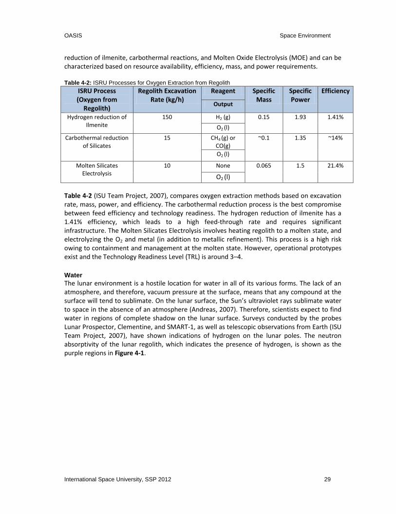
OASIS Space Environment
International Space University, SSP 2012 29
reduction of ilmenite, carbothermal reactions, and Molten Oxide Electrolysis (MOE) and can be characterized based on resource availability, efficiency, mass, and power requirements. Table 4-2: ISRU Processes for Oxygen Extraction from Regolith
ISRU Process (Oxygen from
Regolith)
Regolith Excavation Rate (kg/h)
Reagent Specific Mass
Specific Power
Efficiency
Output
Hydrogen reduction of Ilmenite
150 H2 (g) 0.15 1.93 1.41%
O2 (l)
Carbothermal reduction of Silicates
15 CH4 (g) or CO(g)
~0.1 1.35 ~14%
O2 (l)
Molten Silicates Electrolysis
10 None 0.065 1.5 21.4%
O2 (l)
Table 4-2 (ISU Team Project, 2007), compares oxygen extraction methods based on excavation rate, mass, power, and efficiency. The carbothermal reduction process is the best compromise between feed efficiency and technology readiness. The hydrogen reduction of ilmenite has a 1.41% efficiency, which leads to a high feed-through rate and requires significant infrastructure. The Molten Silicates Electrolysis involves heating regolith to a molten state, and electrolyzing the O2 and metal (in addition to metallic refinement). This process is a high risk owing to containment and management at the molten state. However, operational prototypes exist and the Technology Readiness Level (TRL) is around 3–4.
Water The lunar environment is a hostile location for water in all of its various forms. The lack of an atmosphere, and therefore, vacuum pressure at the surface, means that any compound at the surface will tend to sublimate. On the lunar surface, the Sun’s ultraviolet rays sublimate water to space in the absence of an atmosphere (Andreas, 2007). Therefore, scientists expect to find water in regions of complete shadow on the lunar surface. Surveys conducted by the probes Lunar Prospector, Clementine, and SMART-1, as well as telescopic observations from Earth (ISU Team Project, 2007), have shown indications of hydrogen on the lunar poles. The neutron absorptivity of the lunar regolith, which indicates the presence of hydrogen, is shown as the purple regions in Figure 4-1.

OASIS Space Environment
30 International Space University, SSP 2012
Figure 4-1: Indication of Hydrogen at the Lunar Poles [ISU Team Project, 2007]
The concentrations of exposed hydrogen remain on the order of 150+/-80 ppm (ISU Team Project, 2007) in the craters and permanently shadowed regions at the poles. To confirm the results shown, the Lunar Reconnaissance Orbiter (LRO)/Lunar Crater Observation and Sensing Satellite (LCROSS) mission was conceived. The mission collided one stage of the module with the lunar surface and analyzed the plume it created. The results showed that 4–8% of the plume consisted of water, but that this “represents only the sunlit fraction from the upper surface with speeds sufficient to reach an altitude of 830m” (Dino, 2009). Figure 4-2 illustrates LCROSS’ water identification in blue.
Figure 4-2: Nadir NIR Spectral Identifications in Sorted Spectra [Gibson and Pillinger, 2010]
The nature of the hydrogen deposit could vary in amount and nature, though water ice is the most probable source. Further study has shown that polar water comes in two major forms:

OASIS Space Environment
International Space University, SSP 2012 31
permafrost and cold trap. Lunar cold traps are “zones of the moon permanently obscured where the temperatures are low enough to preserve ice for billions of years” (Carruba and Coradini, 1999). Cold trap water exists around 40 Kelvin, and is so hard that it is nearly impossible to mine. Permafrost water exists on the rim of the polar craters, mixed in with the regolith just below the surface, and can be extracted much more easily with current technology. After the extraction of water, it can be stored in extracted-form or broken down into hydrogen and oxygen through electrolysis. However, electrolysis is a reasonably energetic process requiring 4.71 kWh/kg of water (Bussey and Plescia, 2006), and while this is manageable, it will require a significant source of energy.
Sunlight Most processes that we would expect to undertake at a Lunar OASIS node require electrical energy, and it is important to maximize the availability of solar power from sunlight that can be generated at a given location. The Lunar rotational period is 29.53 days (Williams, 2010); day and night both last roughly 13 days which places a huge demand on a node’s ability to retain generated power. A node would have to store battery power to operate through the 13-day night period. Lunar surveyor Clementine (McKee, 2005) mapped the lunar surface for 71 days in 1994 and identified a Northern polar region that seemingly experiences year-round exposure according to Figure 4-3.
Figure 4-3: Permanently Lit Region of the Moon [McKee, 2005]
There are a few sites spread over roughly 30km where constant access to solar energy is possible. A lunar node placed in one of these permanently lit regions would significantly reduce OASIS’ dependence on stored energy and with sufficient solar generating capacity, would permit OASIS to electrolyze harvested water on demand.
4.2.2 Martian ISRU
In comparison to the Lunar scenario, the ascent from Mars surface to orbit is greater necessitating greater propellant requirements. However, the harsh Mars environment includes low temperatures, large thermal fluctuations, large vertical thermal gradients, and low gravity

OASIS Space Environment
32 International Space University, SSP 2012
making the implementation of ISRU challenging. For instance, a joint Jet Propulsion Laboratory (JPL)-Lockheed-Martin study in 2004 (Badescu, 2010) modeled an ISRU system on Mars which would operate continuously over a period of 16 months utilizing reduction of regolith for water production and CO2 production via a cryogenic process, and the results of the study are in Table 4-3 (Badescu, 2010). Table 4-3: Summary of Mars ISRU Requirements
Process Total feedstock used (in 16 month cycle)
(kg)
Feed-stock rate (kg/hr)
Mass of unit (kg)
Power required (kW)
H2O acquisition 22,500 H20 2.00 3000 24
CO2 acquisition 27,500 CO2 2.40 120 2.9
H2O electrolysis 33,750 H20 2.90 33 7
Liquefying O2 35,000 O2 3.00 105 3.3
Liquefying CH4 10,000 CH4 0.87 74 2.6
The table provides an insight into the power and mass requirements to enable an ISRU system with current technologies. As it can be seen, the mass requirements for the system especially water acquisition is fairly large. The following subsections will detail the possible propellant and life consumable resources which can be found on Mars, as well as their locale, the available concentration, extraction methods, and the difficulties associated these tasks.
Oxygen A vital ISRU product for a Mars mission is Oxygen for use as propellant in ascent from Mars. The amount of oxygen requirement would be driven by the following factors: number of crew members, orbit in which rendezvous would take place, and the required amount of fuel oxidizer. The atmosphere of Mars is 95% carbon dioxide, while the remainder is CO and O2. Thus, the majority of ISRU systems proposed require a supply of pressurized CO2 as feedstock to produce oxygen and hydrocarbons. One suggested method of extracting CO2 from the atmosphere is through the use of a sorption compressor. The main idea is to expose the sorption compressors to the night environment of Mars where CO2 can be adsorbed from Martian atmosphere. During the Martian day, when solar electrical power is available, the adsorbent heat can be applied in a closed volume and CO2 and then released at high pressures. The other methods of producing oxygen from Mars’ atmosphere utilizes the existing CO2 in the atmosphere to produce O2 via the reaction 2CO2 2CO + O2.
Water Water exists in the Martian atmosphere, subsurface, regolith, and polar caps. Missions to Mars such as the Phoenix Mars Lander have confirmed the presence of water near its landing site. While Viking data has shown the Martian sediment to hold 1–3% of water content with a mass density of 1150–1600 kg/m3 (Badescu 2010, p.569), orbiting instruments such as the Mars Odyssey mission have also detected water in the top 1m of the Martian surface, at high latitudes as shown in Figure 4-4.

OASIS Space Environment
International Space University, SSP 2012 33
Figure 4-4: Data from 2001 Mars Odyssey Gamma Ray Spectrometer [NASA, n.d.]
Despite a number of Mars surface missions, the state of water in the equatorial regions could be better determined through improved spatial resolutions of orbital observations. The nature of the Martian atmosphere proposes a new set of challenges to the water acquisition process. The triple point of water on Mars occurs at 0.63kPa and 0°C (Badescu 2010, p.470). The triple point is the point where water can simultaneously exist in all three states. As the Martian atmosphere is close to the triple point, the water content is not stable and makes the process more difficult. For instance, in the southern polar region, the atmospheric pressure is below the triple point which means that the water ice, when warmed, becomes water vapor; water in liquid form cannot be achieved. In comparison, the northern polar region has recorded pressures above the triple point, and liquid water exists but in an unstable form. Additionally, drilling for ice through traditional means would be ineffective; a drill penetrating the icy soil would temporarily melt the ice and upon stopping, would permit the water to refreeze and trap the drill bit.
Sunlight Solar energy from sunlight is a prospective energy source on Mars, although compared to Earth there is an increased distance from the Sun. The mean summer isolation lies between 150W/m2 to 240W/m2, out of a total of 600W/m2 (Badescu 2010, p.83) which is incident on the Martian surface. Through the use of photovoltaic cells, energy can be transformed into electricity. Currently photovoltaic cells convert 15–25% of incident energy into electricity. Additionally, there are dust storms on Mars, which can last several months and significantly affect the sunlight available on the Martian surface.
4.2.3 Phobos and Deimos
Phobos has a radius of roughly 11.2km (Williams, 2010) and gravity roughly 1/20th that of Lunar gravity. The moon orbits Mars frequently with a period of 7h 39min (Williams, 2010) a semi-major axis of only 9,378km (Williams, 2010), and is rotationally synchronous with Mars. Deimos is Mars’ smaller with a diameter half that of Phobos. The moon’s period is 30h 18min (Williams, 2010a), and a semi-major axis 2.5 (Williams, 2010a) times that of Phobos. A node in the

OASIS Space Environment
34 International Space University, SSP 2012
Martian neighborhood would be ideal to place support and resources for Martian access, as well as provide a launch point for further exploration missions. Placing a node on Phobos would allow the node to be outside of Mars’ gravity well, while eliminating the need for station keeping and providing high temporal resolution of the Martian surface. However, the only analyses of Phobos and Deimos thus far show that the regolith of Phobos has MgO (an oxide that can be cracked to produce oxygen) based on albedo observations. As a result, more exploration is required to determine if either Martian moon offers a substantial resource-based advantage for installing a node.
4.2.4 The Asteroid Belt
The asteroid belt between Mars and Jupiter offers any number of potential resource possibilities. The belt is “located between the orbits of Mars and Jupiter from approximately 2–4AU” (Williams, 2004). Some asteroids will be small enough to be collected and transported, while others such as Ceres with a diameter of 946km (Williams, 2004) will be large enough to land on and mine. The main types of asteroids are carbonaceous, stone-like, and metallic. Carbonaceous asteroids consist primarily of hydrated silicates, carbon, organics, opaques, and shock-darkened silicates and compose 75% of surveyed asteroids. Access to organic compounds beyond Earth will aid in supporting biological ecosystems for regenerative life support systems. Silicate hydrates present on the asteroids will form a source of accessible water. Stoney and metallic asteroids are both composed of a significant proportion of metallic elements (more in the latter than the former) and compose 17% and 8% of the asteroid belt respectively. M&S-Class asteroids are thought to be the cores of larger asteroids that survived after collisions disintegrated their parent forms. The asteroid 3554 Amun, an M-class asteroid, is considered to be one of the smallest in its class at 2000m diameter, and contains roughly 30x the total metal mined in human history, and contains 1012g of platinum group metals (valued in the range of $40T (Lewis, 2006)).
Major Belt Objects Vesta and Ceres The asteroid belt is largely unsurveyed at this point and requires a great deal of exploration. Long-range Earth telescopes, as well as flyby missions, provide limited information. The Dawn mission is currently analyzing the asteroid belt, specifically Vesta (the 4th largest asteroid on record) and the dwarf planet Ceres. Vesta is a regolith-coated asteroid resulting from collisions over billions of years as with the rest of the asteroid belt. Early results from the Dawn fly-by indicate that “near the north and south poles, the conditions appear to be favorable for water ice to exist beneath the surface” (Greicius, 2012). Though the Dawn mission has yet to reach it, analysis of Ceres with the Hubble telescope has yielded some interesting data. With a 2006 analysis by the Hubble telescope, new data has given rise to a new hypothesis. “Astronomers suspect that water ice may be buried under the asteroid's crust because the density of Ceres is less than that of the Earth's crust, and because the surface bears spectral evidence of water-bearing minerals” (Beasley and Hendrix, 2005). A differentiated Ceres may look something like the following, Figure 4-5.

OASIS Space Environment
International Space University, SSP 2012 35
Figure 4-5: Hypothetical Ceres' Strata [Pullen, 2009]
Further analysis of the available Ceres data has resulted in the hypothesis that Ceres’ water may be located beneath a thin outer crust of iron-rich clays, (Rivkin, Volquardsen, and Clark, 2006). Ceres’ water-based mantle might take on any number of forms, including liquid, frozen, or a semi-porous mixture. The potential for water on Ceres is very promising for producing abundant rocket-fuel beyond Mars, but will require significant exploration to characterize the water located there.
4.3 Life Support Systems (LSS) and Medicine
Supplying the commodities to provide living conditions for humans can be an additional service of spaceport nodes beyond providing propellant. Humans working or traveling in space will need a controlled environment, including monitored pressure, humidity, temperature, CO2 and oxygen levels. Indeed to avoid toxicity, the CO2 concentration should not exceed 0.3% of the total atmosphere (Clement, 2012a). To prevent fungi proliferation as well as skin and eyes dryness, water vapor has to be closely controlled and be comprised between 0.12 and 0.27 psi (Clement, 2012a). For a good heat balance in the human body, temperatures should range between 18°C and 27°C (Clement, 2012a). Additionally Life Support Systems (LSS) will provide food, oxygen and water, but also water and waste management, to sustain humans stopping at the spaceports. One person per day requires 0.83kg of oxygen, 0.62kg of dry food and 3.56kg of potable water. In addition, shower, laundry, flush, and dishes require 26kg of hygiene water. Studies show that for an extended period of time over 3 months (Clement, 2012a), launching all food, water, and oxygen is more costly than resupplying these goods, thus regenerative life support systems will have to be considered to keep humans alive on a spaceport. To achieve a closed loop, a combination of physico-chemical methods currently used on the ISS - and biological systems (Mitchell, 1994) is the most likely solution. Current water recycling technology aboard the ISS has a “90% or better recycling efficiency” (Rucker, 2012). Physico-chemical methods can revitalize the air and recycle water over long periods of time but providing food on a continuous basis requires bio-regenerative life support systems, involving higher plants. To support 100% of the food for one person, 40 to 50 m2 of continuously cultivated area are needed (Mitchell, 1994), and extraterrestrial greenhouses are a potential method to supply these commodities.

OASIS Space Environment
36 International Space University, SSP 2012
Spaceport nodes can supply next generation space stations and habitats with food, water, and oxygen. This would enable long term human presence in space without resupply from Earth.
4.4 Conclusion
Plasma, micro and partial gravity, as well as radiations and meteoroids constitute specific
hazards for spacecraft and humans at each location, which will have to be accounted for in the
design of the network of spaceports. In situ resources on the Moon include oxygen, water,
metals, carbon and solar energy. Mapping these resources and their quantity is critical for the
establishment of network nodes, as this will eventually enable the reduction of mission mass
and costs and the development of commercial markets. The major resource stockpiles of the
inner solar system as detailed in this chapter are shown in Table 4-4. Table 4-4: Science Summary
Location Gravity Field (m/s
2)
Oxygen availability Water Content Solar Density Flux (W/m
2)
LEO μg N/A N/A 1387
Lunar Surface
1.630 43% of the surface is composed of oxides
Polar ice located in and around permanent shadow craters
1387
Mars Surface
3.711 Processing from CO2 and H2O
Spectral Signature for H2O-ice (North Polar Cap)
597
Deimos 0.003 Exploration Required
Exploration Required
597
Phobos 0.006 Contained in MgO oxides
Exploration Required
597
Asteroid Belt
~μg Identification Required
Identification Required
347-87 From 2-4 AU
Vesta 0.220 Exploration Required
Favorable Conditions Exist at the Poles 248
Ceres 0.270 Exploration Required
Hypothesized within a sub-surface Mantle, in large quantities
Exploration Required
From this table we conclude that the Moon and Mars have the necessary resources for supporting commercial production of propellant. These resources will also enable the establishment of regenerative life support system allowing the presence of humans within the different nodes of the network. This chapter identifies the known locations for oxygen, water and sunlight. Additionally, the locations for further exploration and expansion of the spaceport network are categorized for the near Solar System.
OASIS Spaceport Network
International Space University, SSP 2012 37
5 THE SPACEPORT NETWORK
This chapter outlines the result of the systems engineering analysis of a network of spaceports. The OASIS mission statement, a customer-oriented market study, as well as an evaluation of the distribution and accessibility of extra-terrestrial resources to fulfill the customer’s needs, represented the base for this study. The chapter introduces requirements, an analysis of functions and capabilities and architecture as well as an “existence proof,” which shows a possible architecture created with the presented approach. Elements and standards of the provided architecture are introduced and it concludes with a roadmap for the development of the spaceport network as well as relevant critical technologies.
5.1 Requirements
This section lists the Top-Level requirements as well as the System-Level requirements. The analysis group defined Top-Level requirements based on interdisciplinary considerations by the whole OASIS team. The group then derived the System-Level requirements, listed in Table 5-2 from the Top-Level requirements as reflected in Table 5-1. Table 5-1: Top-Level (TL) Technical Requirements
ID Description
TL.1 The network of spaceports shall provide logistics support for interplanetary transportation and exploration.
TL.2 The network of spaceports shall provide emergency support at every node of the network.
TL.3 The network of spaceports shall utilize in-space resources.
TL.4 The network of spaceports shall provide support to human presence.
TL.5 The network of spaceports shall be extensible and modular.
Table 5-2: System-Level (SL) Technical Requirements
ID Description Response to
ST.1 The network of spaceports shall provide consumables for propulsion and power systems of a spacecraft.
TL.1
ST.2 The network shall provide storage and distribution of cargo and propellant.
TL.1/TL.3
ST.3 The network shall provide repair and maintenance services. TL.1
ST.4 The spaceport network shall provide crewed spacecraft with consumables necessary for life-support systems.
TL.4
ST.5 The network shall provide support for assembly of spacecraft. TL.1
ST.6 The network shall provide support for launch and tug of spacecraft.
TL.1
ST.7 The network shall provide the ability to maintain a docked TL.2

OASIS Spaceport Network
38 International Space University, SSP 2012
spacecraft in case of emergency.
ST.8 The network of spaceports shall use standardized interfaces that comply with the definitions of an international entity.
TL.5
ST.9 Spaceport interface elements with the same function shall be interchangeable and inter-connectable.
TL.5
ST.10 The network shall provide support for docking and landing of a spacecraft.
TL.1
ST.11 The network of spaceports shall provide in situ resource gathering at certain nodes.
TL.3
ST.12 The network shall have the ability of transporting resources and consumables between the different nodes.
TL.3
5.2 Functional and Capability Analysis
By comparing the capabilities of the network with the technical and system-level technical requirements, the network architecture can be verified. This ensures that the capabilities of the network fulfill the requirements.
Table 5-3: Capability and Requirements Matrix
Capabilities/Requirements TL.1
TL
.2
TL.3
TL
.4
TL.5
ST
.1
ST.2
ST
.3
ST.4
ST
.5
ST.6
ST
.7
ST.8
ST
.9
ST.1
0
ST.1
1
ST.1
2
Tug services
x
Repair x
x
Orbit/position alteration x
x
Storage, Loiter/Warm back-up
x
x
Fueling services x
x
Provide shelter for spacecraft in an emergency x x
Landing and launching infrastructure x
x
x
ISRU
x
x
Build infrastructure and lease them
x
Transportation system between the different
nodes/locations x
x
Operational support (e.g. communication, power) x
Providing consumables
x
x x
x
Assembly
x
Modularity and standardized interfaces
x
x x

OASIS Spaceport Network
International Space University, SSP 2012 39
5.3 Architecture
Figure 5-1 provides the overview of the considered nodes. The figure includes the required
velocity change, a gear-ratio (propellant mass to dry mass ratio) and the approximate mission
duration for the important transits. Considering these factors, some of the possibilities were
immediately discarded. Part of the report is the existence proof of the network (Section 5.4). It should be noted that based on different evaluation criteria as well as requirements the reader can derive his/her own network, which suits its purpose best. It should be noted that individual specific networks can be developed by applying the requirements for the network against the different evaluation criteria.
5.3.1 Approach
The DESACMI (Define, Establish, Synthesize, Analyze, Compare, Make a decision, Implement)
method drives the approach for the development of the existence proof (Ryschkewitsch et al.,
2009). The team derived top-level requirements and criteria from the mission statement and
input from the economical and scientific point of view (Chapters 3 and 4). The team identified
possible nodes and performed literature research on those locations. Because of the vast
amount of possible combinations, only the most promising network possibilities (with regards
to velocity change and mission duration) were evaluated.
The “closest” options for the first step were compared against each other with the established criteria. The same approach was used for the choice of the second and third location. After the definition of the network and establishment of its services, missions and related elements are defined, which constitute the network architecture to fulfill the requirements and services.
Evaluation criteria
To ensure a systematic and objective decision making process, a series of evaluation criteria
has been chosen, based on which all the trade-offs regarding the network are made.
The following summarizes the primary criteria taken into account:
Accessibility (Travel time and velocity change required)
Potential for tourism, science research, profitability in general, and exploration at the
node or in proximity
Environment (Gravity, Radiation, Space debris, Temperature gradients, Power
generation, Resources availability)
Costs (Operational and Maintenance, Construction, Development)
Maturity of technology required
Contribution or value of each element for the network

OASIS Spaceport Network
40 International Space University, SSP 2012
Figure 5-1: Network Concept Overview Map
9.4
km/s
HEO
L1M
oo
nL2
0.6
4 km
/s0
.16
gr0
.5 d
4.1
5 km
/s1
.56
gr2
h
2.0
5 km
/s1
.49
gr
4.0
4 km
/s1
.50
gr4
d
Aste
roid
s
LMO
10
km/s
8.6
3 gr
51
0 d
3.4
3 km
/s1
.17
gr4
.5 d
7 km
/s3
.88
gr2
60
d
Mars
4.5
km/s
1.7
7 gr
5 km
/s2
.1 gr
62
1 d
LLO
0.6
5 km
/s0
.16
gr0
.5 d
5.5
km/s
2.4
8 gr
51
0 d
1.4
7 km
/s0
.4 gr
3.7
7 km
/s1
.35
gr3
d
Mars
Mo
on
s
5.5
km/s
2.4
8 gr
26
0 d
0.1
4 km
/s0
.03
gr
5.8
km/s
2.7
2 gr
50
0 d
1.3
8 km
/s0
.37
gr
GEO
1.2
7 km
/s0
.33
gr
3.0
9 km
/s1
.01
gr0
.62
5 d
3.3
km/s
1.1
1 gr
25
0 d
8 km
/s4
.12
gr5
10
d
1-1
.4 km
/s0
.25
-0.3
7 gr
2.1
km/s
0.6
1 gr
Earth
LEO
1.3
8 km
/s0
.37
gr
0.7
7 km
/s0
.19
gr
1.3
1 km
/s0
.35
2.8
3 km
/s0
.90
gr2
55
d
2.9
km/s
0.9
3 gr
24
5 d
0.2
8 km
/s0
.07
grEq
uato
rial 30
0 km
Orb
itLEOLEO
Geo
synch
ron
ou
s altitud
e in
mo
on
’s orb
ital plan
eH
EO
Geo
station
ary Earth O
rbit
GEO
10
0 km
Lun
ar orb
itLLOLLO
L1L2
Earth-M
oo
n Lan
grangian
P
oin
tsLM
OLo
w M
ars Orb
it
4.1
5 km
/s1
.56
gr2
h
Velo
city chan
ge requ
iredP
rop
ellant to
dry m
ass ratioTrip
du
ration
Ho
hm
ann
transfers
No
gravity assistTrip
s back to
LEO co
nsid
er aero
brakin
gC
alculatio
ns to
Ceres are u
sed
as a reference fo
r Astero
ids
No
tes:
1.8
7 km
/s0
.53
gr

OASIS Spaceport Network
International Space University, SSP 2012 41
5.4 Existence Proof
This existence proof presents one possible solution for the node distribution across the network. Figure 5-2 presents the network with its possible destinations and applications. In Figure 5-3, a metro map analogy shows possible “routes” to different destinations and uses involved, similar to metro maps in larger cities.

OASIS Spaceport Network
42 International Space University, SSP 2012
Figure 5-2: OASIS Network Overview
Astero
ids
EML1
Mo
on
EML2
Mars
LEOISS
+
NEA
No
de
2
GEO D
eimo
sPh
ob
os
No
de
3
Service LEOService ISS
Min
ing
Co
mp
anies
Service GEO
Tug to
GEO
ServiceI/P
Missio
ns
Enab
le Mars
settlemen
ts
Increase
Paylo
ad
Sup
ply
Explo
ration
Sup
ply
LLO
LMO
Sup
ply
Inn
er So
lar System
Explo
ration
Sup
ply
Low
EarthO
rbit
No
de
1
LegendN
od
e
Locatio
n
No
de
0
No
de
0
Explo
ration
Ou
ter So
lar Syste
m an
d
be
yon
d
LEO
LLO
EML
NEA
ISS
GEO
LMO
Low
Earth O
rbit
Low
Lun
ar Orb
it
Earth M
oo
n Lagran
gian P
oin
t
Near-Earth
Astero
id
Intern
ation
al Space Statio
n
Geo
station
ary Earth O
rbit
Low
Mars O
rbit

OASIS Spaceport Network
International Space University, SSP 2012 43
Figure 5-3: OASIS Network Metro Map Analogy
5.4.1 Justification
The concretization of the chosen nodes must be made in a structured way, which allows a progressive development of the whole network in the most sustainable and optimized manner. We defined a three step strategy for the establishment of the three node network, which is depicted in Figure 5-4.

OASIS Spaceport Network
44 International Space University, SSP 2012
Figure 5-4: Decision Tree for the Network Existence Proof Approach
Step 1 - LEO vs. HEO vs. EML1/2 For the first step in the development of the network, a location should be identified that could provide an easily accessible point, able to support any kind of missions from the Earth to the Moon and beyond, also a point that allows the creation of a new range of services, leading to a new level of commercialization of space and enabling further development of the network. The business analysis identified several markets in GEO, such as an Orbital Tug and refueling services. Moreover, a research on the future international exploration missions point to the Moon, Mars and locations as far out as Jupiter as being the most common mission destinations. This information allowed defining the desired functions and capabilities for the first node. The locations of LEO, HEO, and EML1/2 were compared in terms of accessibility from the Earth, benefits created in supporting services in GEO, and further network development phases such as for LLO, LMO, and LJO. The HEO possibility was the first to be discarded since it is harder to achieve than LEO and it does not bring advantages in terms of ∆v when compared with EML1/2. To decide between the other two options, we considered example missions destined respectively to the orbits of the Moon, Mars and Jupiter. Table 5-4 presents these results. It should be noted that the mass comparison was only done for EML1 and not EML2. Though EML2 is cheaper ∆v-wise, the difference compared to EML1 is negligibly small.
Step 2 - EML1/2 vs. Moon vs. LLO vs. Mars/Asteroids (Main Belt and Mars crossing) The main objective of the second node is to provide resources to support the services facilitated by the first node. Secondary objectives are to serve as a base for different functionalities, such as tourism and scientific research and to support further Solar System exploration. The second step corresponds to the decision on the location of the second node. Following an analysis on the different possible locations regarding in situ resources gathering,
Earth
Highly ellipticalorbit
Low Earth orbit EML1/2
EML1/2Low Lunar orbit Moon surface
Low Mars orbitPhobos (and
Deimos)Mars surface Asteroids
Step 1
Step 2
Step 3
Phase 1
Phase 2
Phase 3
Mars & Asteroids

OASIS Spaceport Network
International Space University, SSP 2012 45
such as the Moon, Mars, Mars’ moons and asteroids, the Moon appeared to be the most desirable location. This is due to the strong indications of the presence of water, it’s convenient location and easy access regarding the Earth and LEO, which is far from being straightforward in the case of Mars and asteroids. This is what led to the decision that the Moon or its vicinity is the perfect location to place the second node of the network and would play an important role in the solidification of the network. The possibilities for the second spaceport became narrowed to locations in the vicinity of the Moon, such as Moon surface, LLO or EML1/2. The LLO and EML1/2 locations were analyzed as possibilities for storage of resources from the Moon, while at the same time serving as staging stations for supporting further exploration missions. Regarding the support of Solar System exploration missions, the same example cases show that, from a propellant spending point of view, staging in LEO is more advantageous when compared with LLO or EML1/2. These two locations in the vicinity of the Moon were discarded, and the final choice was then to locate the second spaceport on the surface of the Moon, where the presence of gravity also makes it a desirable location for the presence of humans and advancing technologies on a non-Earth planetary environment.
It should be noted that, on a later phase, EML2 can be an important location for the support of missions to further locations in the Solar System. The placement of a water or propellant depot in EML2 shall bring reductions on the operation costs when compared with sending these consumables to LEO. This option should be further analyzed, in a further phase, out of the scope of this study.
Step 3 - LMO vs. Mars surface vs. Mars Moons vs. Asteroids (Main Belt and Mars crossing) According to the mission statement of the network of spaceports the following step should enable a progressive expansion to other planets of the Solar System. The planet of Mars has always presented itself as a milestone for the age of humanity in space, not only for its natural resources, but also for the cultural and philosophical weight. However, with current technology it is not possible to land heavy payloads (50 – 60 tons) in a safe manner on the surface of Mars, thus the location of the third node was chosen with particular focus on how to provide support for the exploration of Mars and further beyond. Having ruled out the Mars surface, three locations stand out as possible candidates: Low Mars Orbit (LMO), Mars moons (Phobos or Deimos) and Asteroids (Main Belt and Mars crossing). Though asteroids might be rich on resources (e.g. water on Ceres), locating the node on an asteroid was discarded due to a greater distance and more expensive access (phasing of orbits) to Mars when compared with LMO and Mars moons. Nevertheless, wet asteroids are considered the main source for resources. The main difference between LMO and Mars moons is, even though Phobos and Deimos present a very small gravitational field, they offer a fixed location for having a propellant factory and docking station for spacecraft destined to Mars and beyond, which cuts the costs related with station keeping maneuvers necessary in orbit, while also offering possibilities of ISRU. Between the Mars moons, Phobos and Deimos, the choice went for the former due to its greater size and closer location to Mars.

OASIS Spaceport Network
46 International Space University, SSP 2012
Propellant Mass Comparison To compare the propellant needs between the different staging possibilities, they were compared to a baseline (from Earth surface directly to the respective target). The assumptions are that a propellant depot is available at the staging point, and the propellant mass to deliver the propellant to the staging point is not included. The specific impulse was assumed to be constant and 450s. Based on the Tsiolkovsky rocket equation,
(
),
when re-arranged:
,
where is the mass of the propellant, is the dry mass of the spacecraft, is the
specific impulse, is the gravitational acceleration of Earth and is the required change in velocity for an orbital maneuver. Normalizing the ratio with respect to the baseline, we can compare different staging routes. The results can be seen in Table 5-4.
Table 5-4: Propellant Mass Comparison for Different Staging Points
Mission Staging %
Moon Earth Surface -> LLO (baseline) 100%
Earth Surface -> L1 -> LLO 95%
Earth Surface -> LEO -> L1 -> LLO 45%
Earth Surface -> LEO -> LLO 44%
Mars Earth Surface -> LMO (baseline) 100%
Earth Surface -> L1 -> LMO 74%
Earth Surface -> LEO -> L1 -> LMO 39%
Earth Surface -> LEO -> LMO 35%
Jupiter Earth Surface -> LEO -> Jupiter Orbit (baseline)
100%
Earth Surface -> LEO -> MM -> Jupiter Orbit 53%
5.4.2 Node Description
By taking into account the evaluation criteria presented previously, three nodes were selected for the spaceport network: LEO, the Moon surface and Phobos. The main characteristics of each node are presented; identifying the most attractive locations to the network.
Spaceport Node 1 - LEO The Low Earth Orbit node would allow servicing of GEO satellites by tugging them from LEO to GEO. This would reduce the launch cost of these satellites, enabling the use of smaller launchers (Bienhoff, 2010) to put similar satellites into orbit. Reducing the launchers’ mass, or increasing its payload, would also be a great advantage for missions to the Moon (Bienhoff, 2010) and Mars, where this node could be considered as the main staging point for missions up to Mars. Furthermore, the possibility of servicing LEO satellites, the ISS and next generation

OASIS Spaceport Network
International Space University, SSP 2012 47
space stations is also a capability that makes this node the most fundamental in the proposed first phase of the network.
Spaceport Node 2 - Moon surface The Moon has been considered a top exploration target for most of the space agencies in the world, with eight missions planned until 2020. Its potential as a space tourism destination opens the door for private investment and the resources available on the surface enable the possibility of in situ production of propellants, solar panels and habitation modules. The resources could be useful to support Spaceport Node 1 in LEO and represent an important stepping stone towards the development of Spaceport Node 3 on Phobos. This would come in two ways: first it would be important for the development of technologies to be used on the third phase of the network, and second, it would be essential to provide resources needed during the implementation and exploration of this third phase.
Spaceport Node 3 - Phobos The third step on the development of the spaceport network would be the implementation of a node on Phobos. Mars and its orbits have been identified as important goals of space exploration for many space agencies, and at the moment, 6 missions are planned to these locations until 2025. Phobos allows an easier access to the Mars surface and the low gravity field of Phobos facilitates access to its surface. This provides an advantage when compared to going directly to the Mars surface. Even though the presence of resources on Phobos is still not fully proven, the small ∆v that is required to reach locations where the confidence in finding useful resources for propellant is high, makes Phobos a very attractive location for the third node of the network. Besides transporting water from Spaceport Node 2, other possible water sources that are accessible from Phobos include near-Mars asteroids, main belt asteroids (e.g. Ceres) and the Mars surface.
5.4.3 Network Elements and Standards
From the services and missions identified by the business case, elements and standards required for the network of spaceports are identified. These elements and standards will be discussed for each node.
Spaceport Node 1 At Spaceport Node 1, the orbital platform provides support like power generation, station keeping, communication, navigation, and docking support to the other elements. An international docking adapter allows different spacecraft to dock. Water tanks connected to the propellant generators (via electrolysis) are directly connected to the tug servicer. It should be noted that the system is modular and more elements can be added to increase the needed capability. Finally, it will provide cryogenic (LO2 and LH2) consumables to service any spacecraft.
Spaceport Node 2 - Moon Base On the Moon surface, apart from operational support such as power generation and communications, a system of elements will be set up. An excavator will gather resources, and an ISRU plant will transform it into water. There will be a facility for propellant generation to generate propellant for the lander, which is used to lift the water tanks into orbit. Storage for water is provided. Another part of the Moon surface infrastructure will be a spaceport Vertical

OASIS Spaceport Network
48 International Space University, SSP 2012
Takeoff Vertical Landing (VTVL) pad that enables spacecraft to launch and land safely and accurately through the use of navigation beacons. Later on, consumables for life support systems (Oxygen, fresh water, and food) will be provided for a human presence.
Spaceport Node 3 - Phobos Base A base on Phobos will be similar to a base on the Moon with operational support, possible propellant generation, propellant storage infrastructure and a port for transportation of resources from wet asteroids (e.g. Ceres) or transportation of people to Earth and other spaceports. Regarding asteroid mining, going to the asteroids and getting in situ resources is one option. The other one is to capture the asteroid and transport it to the Mars orbit to extract the resources there. Different types of spacecraft will be used for the variety of services ranging from human space travel to resource transportation. Between the infrastructures, a surface transportation system cannot be used; the gravity is extremely low on Phobos. Instead, a “clamp-on” railway or “tethered” system might be implemented.
Orbital Platform (OP) Serves as a connecting element (using the international docking standard and providing adapters for other docking mechanisms) for the mobile water tanks and tug servicers. Produces propellant from the water tanks directly to the tug. Provides the other elements with on-orbit necessities and power. Also, serves as a communications relay to Earth for other missions and spacecraft.
Tug Servicer (TS) A reusable spacecraft, which projects the services of the node to other locations. Modularity and the ability to stack multiple spacecraft enable missions beyond the baseline GEO. Offers passive storage of cryogenics and therefore serves as a propellant tank. Robotic equipment enables servicing of other spacecraft. Moreover, it can be used to place other spacecraft in the desired orbit.
Mobile Water Tank (MWT) The purpose of the mobile water tank is to transport water between LLO and LEO. Also serves as storage tank at the orbital platform.
Moon Surface Shuttle (MSS) A reusable ascent and descent stage used to bring up Mobile Water Tanks and Cryogenic Tanks to LLO and deorbit empty tanks to the Lunar surface.
Small Water Tank (SWT)
Small water tank for the transportation of water between LLO and Moon surface.
Small Cryogenic Tank (CPT)
Tank is used to transport propellant between LLO and Moon surface to refuel the tug servicer
before the return to LEO.
Moon Surface Elements
Moon surface elements are comprised of regolith excavators and haulers, a propellant
generation facility, a launch and landing pad, a resource and propellant storage and
distribution facility as well as a control center to provide the node with the necessary

OASIS Spaceport Network
International Space University, SSP 2012 49
subsystems and support equipment. The node also provides consumables for life support
systems for a possible human presence. Surface transportation between the spread-out
facilities is provided by the haulers.
Phobos Surface Elements
Phobos surface elements are comprised of a propellant generation facility, a port for arriving
and departing spacecraft, as well as resource and propellant tanks. It can be used as a staging
point before a Mars Entry, Descent and Landing (EDL) or departure to Earth. A control center,
analogous to the Moon, provides the necessary subsystems and communications to Earth. A
transportation system between the facilities could be provided by propulsive hopper vehicles
or a tethered railway system.
Mobile Resources Gatherer (MRG)
Spacecraft visiting asteroids with different tools to enable extraction of resources on different
surface conditions. Fills up the electric water tug.
Electric Water Tug (EWT)
The electric water tug is equipped with electric propulsion and used to transport water from
asteroids to the propellant generating facilities on Phobos.
Standards To enable easier operations between different nodes and to reduce the number of parts and procedures that need to be developed, the team proposes to standardize several elements of the spaceport network. To facilitate international cooperation and avoid miscommunication, the metric system of units should be used throughout the design, construction and operation of the network. A major part of the operation of the network is rendezvous and docking. To make the network easily expandable, standardization should be made to the software enabling automated rendezvous and docking throughout the network. Additionally, all docking ports with the same functions across different spacecraft, tanks, ascent/descent modules and surface structures could use the International Docking Standard System (ISS MCB, 2011) or similar. Standardization includes the quick disconnect fluid couplings for transferring water or propellant and the electrical and data interface between any two components. To enable simpler manufacturing and the ability to perform simple repair and maintenance in situ all nuts, bolts, fasteners on any module should be operable by standard tools. To streamline mission operations orbital maneuvers and transfers (e.g. LEO to GEO boost) should be standardized. For each possible mission this includes standard apogees, perigees, rocket burn times and transfer times. To simplify the production of propellant from water the systems working at the different nodes should use similar principles though they might be scaled differently in size. Surface vehicles should have a common core on which tools for a specialized task and tanks can be mounted.

OASIS Spaceport Network
50 International Space University, SSP 2012
5.4.4 Verification
The purpose of this section is to cross-check the capabilities of the network against the elements to guarantee that every element has a purpose and every capability is achieved. Table 5-5: Capabilities versus Elements
Capabilities/Elements
Orb
ita
l p
latfo
rm
Tu
g s
erv
ice
r
Mo
bile
Wa
ter
Ta
nk
Mo
on S
hu
ttle
Sm
all
Wa
ter
Ta
nk
Sm
all
Cry
og
en
ic T
an
k
Mo
on S
urf
ace
Ele
me
nts
Ph
ob
os S
urf
ace
ele
me
nts
Ele
ctr
ic W
ate
r T
ug
Mo
bile
Reso
urc
es
Ga
the
rer
Tug services
x
x
x
Repair
x
Orbit/position alteration
x
Storage, Loiter/Warm back-up x
x
Fueling services
x
x
x x
Provide shelter for spacecraft in emergency
x
Landing and launching infrastructure x
x x
In Situ Resource Utilization (ISRU)
x
x
Transportation system between the different nodes/locations
x x x
x
x
Operational support x
x x
Providing consumables x
x
x x
Assembly x
x x
Modularity and standardized interfaces x x x x
x x
x
5.4.5 Roadmap
To map the development of the network over time, a roadmap for the implementation of the different parts is used. The detailed roadmap can be seen in Figure 5-5. Each phase logically deals primarily with the construction of one node, and different phases overlap over time. The construction of a node can further be subdivided into precursor missions, building of the fundamental elements that enable the capabilities of the node, adding of additional desired features and operations. Every phase depends on the availability of some critical technologies. These are summarized in Table 5-7, whereas Table 5-6 shows the relevant technology areas (NRC, 2012). Agency investments, academic competitions (e.g. NASA Lunabotics Mining Competition, Revolutionary Aerospace Systems Concepts-Academic Linkage, AIAA Student Competitions) and financial challenges (e.g. NASA Challenges, Google Lunar X-Prize) could accelerate development of these technologies. Moreover, analogous test sites such as the proposed International Lunar Research Park in Hawaii could test the technologies in an appropriate environment.
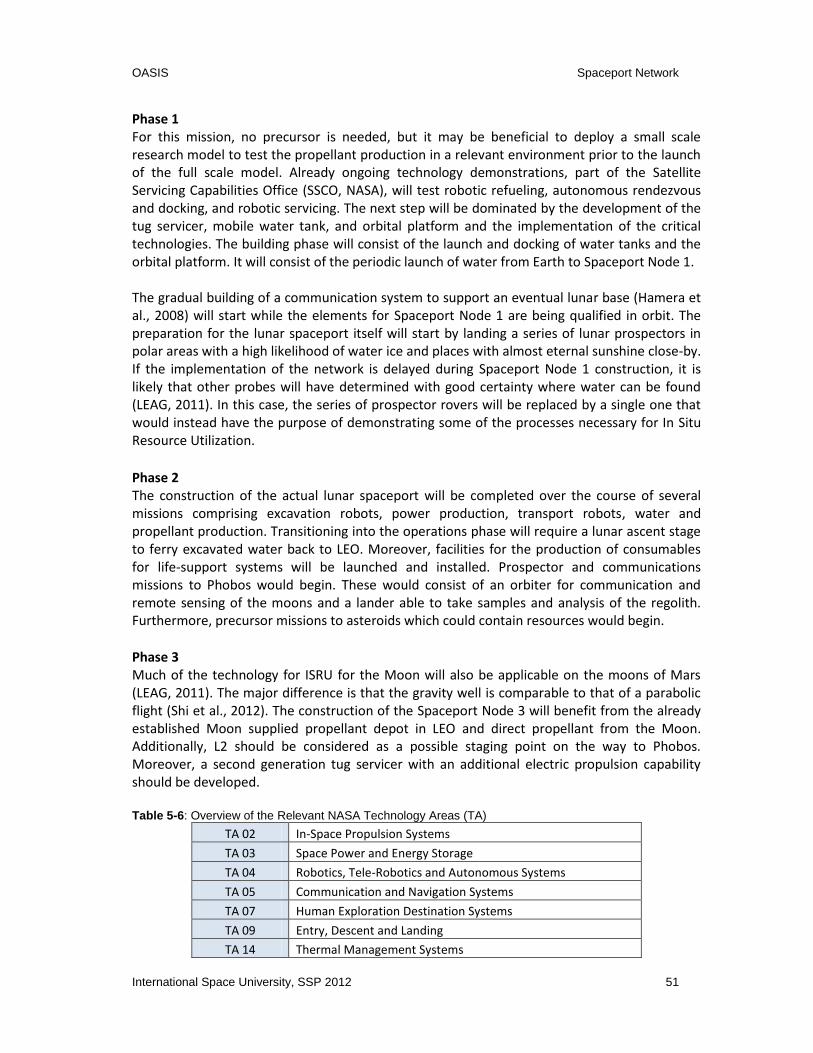
OASIS Spaceport Network
International Space University, SSP 2012 51
Phase 1 For this mission, no precursor is needed, but it may be beneficial to deploy a small scale research model to test the propellant production in a relevant environment prior to the launch of the full scale model. Already ongoing technology demonstrations, part of the Satellite Servicing Capabilities Office (SSCO, NASA), will test robotic refueling, autonomous rendezvous and docking, and robotic servicing. The next step will be dominated by the development of the tug servicer, mobile water tank, and orbital platform and the implementation of the critical technologies. The building phase will consist of the launch and docking of water tanks and the orbital platform. It will consist of the periodic launch of water from Earth to Spaceport Node 1. The gradual building of a communication system to support an eventual lunar base (Hamera et al., 2008) will start while the elements for Spaceport Node 1 are being qualified in orbit. The preparation for the lunar spaceport itself will start by landing a series of lunar prospectors in polar areas with a high likelihood of water ice and places with almost eternal sunshine close-by. If the implementation of the network is delayed during Spaceport Node 1 construction, it is likely that other probes will have determined with good certainty where water can be found (LEAG, 2011). In this case, the series of prospector rovers will be replaced by a single one that would instead have the purpose of demonstrating some of the processes necessary for In Situ Resource Utilization.
Phase 2 The construction of the actual lunar spaceport will be completed over the course of several missions comprising excavation robots, power production, transport robots, water and propellant production. Transitioning into the operations phase will require a lunar ascent stage to ferry excavated water back to LEO. Moreover, facilities for the production of consumables for life-support systems will be launched and installed. Prospector and communications missions to Phobos would begin. These would consist of an orbiter for communication and remote sensing of the moons and a lander able to take samples and analysis of the regolith. Furthermore, precursor missions to asteroids which could contain resources would begin.
Phase 3 Much of the technology for ISRU for the Moon will also be applicable on the moons of Mars (LEAG, 2011). The major difference is that the gravity well is comparable to that of a parabolic flight (Shi et al., 2012). The construction of the Spaceport Node 3 will benefit from the already established Moon supplied propellant depot in LEO and direct propellant from the Moon. Additionally, L2 should be considered as a possible staging point on the way to Phobos. Moreover, a second generation tug servicer with an additional electric propulsion capability should be developed. Table 5-6: Overview of the Relevant NASA Technology Areas (TA)
TA 02 In-Space Propulsion Systems
TA 03 Space Power and Energy Storage
TA 04 Robotics, Tele-Robotics and Autonomous Systems
TA 05 Communication and Navigation Systems
TA 07 Human Exploration Destination Systems
TA 09 Entry, Descent and Landing
TA 14 Thermal Management Systems

OASIS Spaceport Network
52 International Space University, SSP 2012
Figure 5-5: Roadmap for the Proposed Network Architecture
20
12
MISSIONSELEMENTS AND TECHNOLOGIES
PH
ASE 1
EN
HA
NC
EM
EN
TS
PH
ASE 2
PH
ASE 3
20
15
20
20
20
25
20
30
20
35
20
40
20
45
Lu
nar P
ola
r
Pro
specto
r
Op
era
tion
Sta
rt
Asse
mb
ly
of N
od
e 1
Tu
g
Serv
icer
Orb
ital
Pla
tform
Mo
bile
Wate
r Tan
k
Fu
ll Sca
le IS
RU
An
alo
g T
estin
g
Sm
all S
cale
ISR
U
Testin
g o
n th
e M
oo
n
Co
mm
un
icatio
ns
Rela
y fo
r the M
oo
n
Exp
lora
tion
of
Ph
ob
os a
nd
Deim
os
GR
AD
UA
L EX
TEN
SIO
N
OF N
OD
E 2
Pro
spect P
ote
ntia
l
Reso
urce
s on
Aste
roid
s
Reu
sab
le
Lu
nar L
an
der
Reg
olith
Exca
vato
r
Mo
on
Su
rface
Facilitie
s
Hau
ler
Sm
all W
ate
r
Tan
k
Sm
all
Cry
og
en
ic Tan
k
Co
nstru
ction
of N
od
e 2
Op
era
tion
Sta
rt
Op
era
tion
Sta
rt
Ad
van
ced
Tu
g S
erv
icer
Ph
ob
os S
urfa
ce
Facilitie
s
Co
nstru
ction
of N
od
e 3
Reso
urce
Gath
erin
g a
nd
Tra
nsp
ort to
Ph
ob
os
NETWORK FULLY OPERATIONAL
Mo
bile
Reso
urce
Gath
ere
r
Ele
ctric
Wate
r Tu
g
GR
AD
UA
L EX
TEN
SIO
N
OF N
OD
E 1
Sm
all S
cale
An
alo
g T
est
LEG
EN
D
Ele
men
t
Missio
n
On
go
ing
Missio
n(s)
TEC
HN
OLO
GY
In-S
pace
Pro
pu
lsion
Tech
no
log
ies (T
A 0
2)
Sp
ace
Po
wer &
En
erg
ies
(TA
03)
Ro
bo
tics, Tele
-Ro
bo
tics an
d
Au
ton
om
ou
s Syste
ms (T
A 0
4)
Co
mm
un
icatio
n a
nd
Navig
atio
n S
yste
ms (T
A 0
5)
Hu
man
Exp
lora
tion
Destin
atio
n S
yste
ms (T
A 0
7)
En
try, D
esce
nt a
nd
Lan
din
g
(TA
09)
Tech
no
log
y R
ead
iness
Level
2
Co
mm
un
icatio
ns
Rela
y fo
r Ph
ob
os
3
Reu
sab
le
Cry
og
en
ic En
gin
es
3
On
-Orb
it
Refu
elin
g
3
Au
ton
om
ou
s
Ren
dezv
ou
s
& D
ock
ing
4
Hig
h-O
utp
ut
Po
wer S
yste
ms
4D
ep
loyab
le
Aero
bra
ke
3
Sto
ichio
metric (8
:1)
Cry
og
en
ic En
gin
es
2
Hig
h B
an
dw
idth
Co
mm
un
icatio
n
4U
ltra C
old
Lu
nar
Ice E
xcavatio
n
2
Reg
olith
Pro
cessin
g
4
Lo
w B
oil-O
ff
Cry
og
en
ic Tan
ks
3A
dvan
ced
Pro
pu
lsion
3
En
han
ced
Deep
Sp
ace
Navig
atio
n
2
So
lar P
an
el
Pro
du
ction
on
Mo
on
3
Lo
sely
-sup
erv
ised
Au
ton
om
ou
s Ro
bo
tics
3
Tele
-op
era
ted
Ro
bo
tics
5
On
-Orb
it Pro
pella
nt
Pro
du
ction
4

OASIS Spaceport Network
International Space University, SSP 2012 53
Table 5-7: Overview of Critical Technologies by Phase
Critical Technology TRL TA Comment
Phase 1 On-orbit propellant production
(LH2 and LO2)
4 07 Propellant production by electrolysis of
water takes place at Spaceport Node 1
On-orbit refueling 3-4 02 Necessary for profitable tug operations
Reusable cryogenic rocket engines 3-4 02 Necessary for profitable tug operations
High-output power systems 3-5 03 Needed for electrolysis
Deployable aerobrake thermal
protection system
2-4 09 Soft aerobraking is performed from GEO
to LEO
Autonomous rendezvous and docking 4-5 04 Unmanned systems
Phase 2
Ultra cold Lunar ice excavators 2 07 Needed for Lunar ISRU
Regolith processing facilities 4-5 07 Needed for Lunar ISRU to extract water
Tele-operated robotics for Lunar base
operations
5 04 Needed for unmanned Lunar ISRU
systems
Reusable Moon Surface Shuttle 3-4 09 To refuel the tug and bring water to LLO
Stoichiometric ratio (8:1) cryogenic
engines
2 02 To utilize the mined water better
High bandwidth communication
(e.g. optical)
3-4 05 For HD video from the moon to support
tele-operation
Solar panel production on Moon from
regolith
3 07 Launch cost reduction through ISRU
Launch pad on Moon surface 4 07 To avoid dust contamination
Low boil-off cryogenic propellant tanks
(Kutter et al., 2005)
3-4 02 Needed for profitable propellant storage
in space
Phase 3
Loosely-supervised autonomous robotics
(Fink et al., 2011)
3-5 04 Unmanned systems, unacceptable time-
delay for tele-operation
Advanced Propulsion 3 02 Reduce transport time and increase
efficiency
Enhanced Deep Space Navigation 2 05 To enable reliable and precise navigation
5.5 Summary and Conclusion
The network concept introduces possible pathways to the creation of a transportation infrastructure in space which supports the bigger vision of Solar System mobility. Though the main parts of the network are robotic, the network supports human exploration by reducing the costs of propellant, increasing the payload capabilities and providing consumables for life support systems through the use of in situ resources and new mission architectures. The team presented an existence proof with three nodes and provided descriptions of the nodes and elements inside the network. We justified the chosen architecture and verified it against the services and capabilities. Finally, the roadmap indicates a possible order required to achieve a network with corresponding critical technologies identified.

OASIS Law, Policy, and Society
54 International Space University, SSP 2012
6 LAW, POLICY, AND SOCIETY
6.1 Introduction
“Competition has shown to be useful up to a certain point and no further, but
cooperation, which is the thing we must strive for today, begins where competition
leaves off.”
-Franklin D. Roosevelt, 1882-1945
A spaceport network is not only a technical issue, but it also involves policy and law, and
society. For example, the cancellation of NASA’s Constellation Program was due to lacking
financial, managerial, and political support, not for technical reasons. In this chapter, the
political, legal, and societal framework for the feasibility of OASIS will be identified.
6.2 OASIS Project Political Steps
The notion of a space-based network of spaceports will trigger a political debate. To secure the project vision and enable mission success, a framework of political initiatives has been identified. Strategic planning methods are to be established with careful consideration placed on previous mission examples.
6.2.1 ISECG as a Starting Point
In 2006, 14 space agencies began a series of discussions on global interests in space exploration. Together they took the unprecedented step of elaborating a vision for peaceful robotic and human space exploration and they formed the International Space Exploration Coordination Group (ISECG). Since OASIS envisions facilitating space missions and exploration, ISECG is the ideal starting point to promote and support the project at a state level; firstly, it is an internationally accepted initiative and, secondly, because among the members there are the most important and advanced space-faring states represented by space agencies closely tightened with the governments. Given the above-mentioned reasons, the ISECG structure is the ideal basis for the promotion of OASIS. During ISECG proceedings, countries share the status of their programs and plans as they pertain to space activities through their national space agencies. Moreover, these space agencies share insights into the existing and emerging policies within their nations. It is necessary to understand these policies and plans, the common elements, and the common trends to reach a strategic consensus. (Junichiro, 2011)
6.2.2 The International Cooperation
According to a public-private partnership model, state funding is the primary source at the first
level. To achieve that, international cooperation is necessary. There are multiple important

OASIS Law, Policy, and Society
International Space University, SSP 2012 55
political benefits for the states that put together an international cooperation project;
International cooperation in space activities has the potential to reduce a partner’s costs by
spreading the burden to other nations. Although additional overhead costs increase, as a result
of any international cooperative endeavor, these costs are spread among the partners.
Furthermore, international cooperation generates diplomatic prestige as well as political
sustainability. Another very important political benefit is that international cooperation enables
workforce stability; one large program brings a relatively large number of jobs and amount of
revenue.
Entering into a long-term international space program is an option to participate in ambitious goals that are not affordable by only one state. When a country decides to enter into international agreements, cooperation is required that all partners fulfill all agreed upon parameters. It is not as easy to make drastic changes to state politics. Therefore, space policy is much more stable with long-term objectives and without sudden major changes and political shifts. A stable policy without twists and turns every election year makes allows long-term vision.
For the purposes of OASIS, there shall be incentives to cooperate with nations that cannot
contribute a unique capability, that are not able to provide an existing capability, goodwill
nations, or nations that are heavily capable. Nevertheless, balance should be kept between
technical interdependency and redundancy. A nation shall not be “held hostage” by the policy,
schedule, or budgetary difficulties of its partners. Based on that, there might be a natural
hierarchy of partner nations among those who have more control, the de-facto decision making
power, and those that are out of the critical path during the cooperation procedure, as well as
those who provide the extraneous capabilities, but have little in the way of programmatic
influence.
In conclusion, the benefits of joining ISPA will be multiple for states. By participating in such an
Organization, ISPA promotes the different state space programs, boosts national prestige due
to the innovative character of the OASIS project, develops technical capabilities, and shares the
cost through the channel of international cooperation enhancing and strengthening
international relations.
6.3 The OASIS Model
6.3.1 Scope of Political and Legal Entity
The OASIS project has identified a new governing authority for the viable execution of the
proposed network of spaceports. Based on the purpose of the International Space Exploration
Coordination Group (ISECG), this authority would provide a forum for member agencies to
share their objectives, plans, explore collaborative concepts, and formulate preprogram
international partnerships. Potential governing models are listed below:
National governmental authority run by a single space-faring nation
Intergovernmental organization
OASIS Law, Policy, and Society
56 International Space University, SSP 2012
Private company registered in a single country
Fully or partially state-owned company
Transnational corporation
Non-profit organization
Consortium of private companies
Public Authority-Governmental Contractor (Port Authority)
The Intergovernmental organization-transnational corporation provides the most practical legal
and business model for OASIS. OASIS suggests an innovative model of public-private
partnership that involves the creation of a new intergovernmental authority, the International
Spaceports Authority (ISPA). ISPA consists of the fourteen ISECG members and will contract a
transnational corporation in order to develop the project. (See Table 11-1 in Appendix for
Legal Entity Options Description.)
Considering the scope of services provided, and the need of long-term support, the legal entity
of the OASIS project has to combine state reliability and private management flexibility both on
an international level. Unlike the ISS management, the OASIS spaceport will require the
creation of a legal personality to provide commercialized services.
Diverse legal models could fulfill these requirements, but as a transport interface in space
investigations into analog transport infrastructure based on earth suggest that the "port
authority" model fulfills all of our needs. The model allows a public entity to plan, facilitate, and
regulate the initial construction and port extension when the operator cannot support the large
amount of capital needed. The port operator, managed by a private entity, operates, develops,
and provides services to customers. That model combines creation of vital connections for the
public, acts as a commercial space business incubator, provides safety management and allows
creation of values and taxes incomes for member states.
As seen in the policy sub section, international cooperation is one of the major drivers of the
project. As the last evolution of ISECG involvement, the best compromise approach would
require the creation of an international organization designated as the "International Spaceport
Authority" (ISPA), and the creation of a private transnational company designed as the
Spaceport Company (SPC) registered in one country to assemble and operate the OASIS.
6.3.2 The Governing Authority
From a top-level perspective, the political questions that must be answered involve
determining the necessary framework to enable international participation. The governing
body will play an important role in supporting this endeavor: it should be international and
financially cooperative, it should map out a framework for enabling negotiations (internal and
external) and conflict resolution, and it should also regulate the spaceport.
To determine the best strategy and political framework for the OASIS governing authority, it is
necessary to take into consideration the lessons learned from the International Space Station
(ISS). The feasibility of the project relies on accommodation of a partner’s own objectives,

OASIS Law, Policy, and Society
International Space University, SSP 2012 57
establishment of realistic expectations, usage of clear mission objectives to drive support,
establishment of appropriate dependencies, planning of an evolving public policy and early
achievements, application of common standards and tools for the development of the project,
identification of programmatic and public outreach milestones that demonstrate tangible
benefits to the public, and employment of reference missions in order to define
requirements.(Laurini, Karabadzhak, Satoh, Hufendbah, 2011)
Based on the above-mentioned notions, OASIS recommends the creation of a new
international organization, the International Spaceports Authority (ISPA) that will unify the
ISECG states, and any other states interested in joining the project. It will culminate in the
development of the spaceports network, and will provide the necessary framework for a
sustainable and efficient international cooperation.
This governmental authority will enable an integrated program, which will lead to more
efficient sharing of costs while reducing duplication of effort in research and technology
development, design, production and infrastructure. ISPA independently manages the funding
and securing of full cooperation between states. Moreover, it will elaborate and implement a
long-term space policy, by recommending space objectives to its member states, and will
concert the policies of these states with respect to other national and international
organizations and institutions. By using the existing industrial potential of all member states,
ISPA ensures that space technology will be developed and maintained, and will encourage the
rationalization and development of an industrial structure appropriate to the market
requirements. ISPA should also draft agreements and provide a regulatory framework
concerning diplomatic relations, negotiations, state-to-state reciprocity and conflict resolution.
OASIS recommends that ISPA represent every continent, including ISECG members, and ISPA
shall be open to all states with either a developed or developing space programs.
6.3.3 The Agreements
As it has already been stated, ISPA will be created by the unification of the ISECG members. A
Memorandum of Understanding (MoU) will be signed among the states that will provide the
initial framework for the smooth operation of ISPA and OASIS activities. All basic norms and
principles will be in this MoU; for instance, all ISPA members will participate in an equitable
manner, regarding their financial contribution. The distribution of power in ISPA and the
decision-making power will correlate to the members’ financial contribution, as well as the
possession of capacities and positional strength.
Nevertheless, after the initialization of OASIS activities and in order to provide a long term secured framework, as with all intergovernmental organizations, ISPA will need to rule by a binding intergovernmental agreement designated as the ISPA Treaty; it should be created under the United Nations Vienna Convention on the Law of Treaties and will be based on the already existing MoU. The first goal of that agreement is to ensure spaceport activities with international law. The agreement states the scope of activities, regulates spaceport activities, enables efficient international cooperation and duties, and provides conflict resolutions. Under this legal structure, the ISPA treaty shall define duties between ISPA and the SPC. As a

OASIS Law, Policy, and Society
58 International Space University, SSP 2012
private entity, all activities of the SPC shall be monitored by its state of registration and/or any launching states contributing to the assembly of the spaceport. The ISPA shall deliver customer authorizations to approach facilities under a licensing regime of technical regulations, control insurance, and indemnification warranties, following the example of the Federal Aviation Administration (FAA). That is why unlike the International Space Station Intergovernmental Agreement (ISS IGA) creating a cross waiver of liability between States parties, this model is not adapted to the OASIS project. Regarding the "port" nature of the activities, the ISPA shall be able to sue any customers creating damages to OASIS spaceport facilities. By providing services in a network of hubs, activities will involve high traffic of space vehicles regulated under a licensing regime written by the International Spaceports Authority.
As a long-term framework of cooperation, the ISS IGA illustrates the station's history where all member states keep jurisdiction both on their registered facilities and on their crew. Consequently, each member state keeps ownership on their own contribution to the space complex, likewise the station is not international. Through its legal identity, ISPA can register all elements of OASIS and keep jurisdiction. All on Earth operations, launching, contributions to launch, and assembling of the Spaceport shall be operated by member states for the benefit of ISPA. The OASIS treaty negotiates the risk sharing among member states.
In the case of a breach of the ISPA Treaty, the principles of Article 60 in the Vienna Convention
on the Law of Treaties apply.
6.3.4. The Private Partner - The Spaceports Company
The OASIS partnership model proposes that ISPA shall have a partnership with the private
sector, a transnational corporation, the Spaceports Company. This partnership will take place
through a request for proposal or call for tenders by ISPA to get private industry involved and
submit proposals related to the management and operation of the spaceports network.
The political benefits from such a partnership are numerous; it is a way of developing local
private sector capabilities through subcontracting opportunities for local or national firms, as
well as exposing state owned enterprises. It also creates diversification in the economy by
making the country more competitive in terms of its facilitating infrastructure base as well as
giving a boost to its business and industry associated with infrastructure development, while
also supplementing limited public sector capacities and getting it prepared for future demand.
Under our legal model, the Spaceport Company is a transnational private company registered in one country with ISPA member states as shareholders. The link between ISPA and SPC is the critical point where the international organization directly mandates the company, or the member states agree within ISPA and control the SPC as a capital shareholder. That second option is more realistic and has been successful in many cases like in Europe where national space agencies are members of an intergovernmental organization, ESA and at the same time shareholders in the commercial window, Arianespace among private partners. Given the scope of the Spaceports Company, a full private investment

OASIS Law, Policy, and Society
International Space University, SSP 2012 59
is not a realistic option as a full public investment considering the reduction of capacity of public investment. Given the potential profitability of the project demonstrated in business studies, private entities will have access to the OASIS spaceport capital as a way to leverage more financial capabilities, resulting in public private shareholders. Among key points of a space program the contract tool management is critical; an inappropriate contracting tool can sink a strong technical project. Though space programs costs are under more scrutiny, the use of public-private partnerships (PPP) allows development of infrastructure with a minimum public investment. (ISU Team Project, 2011) However, the last success in the use of PPP displayed extreme caution. There are many models where the risk is not correctly balanced among partners, leading to difficulties with business cost and finally a shift from partner to prime contractor under the management of the public entity.
6.4 Securing the Project from a Legal Perspective
To provide a securing legal framework to enhance the feasibility and efficiency of the activities,
OASIS has taken into consideration both general law principles as well as specific notions that
might result into implications in the different stages of the project.
6.4.1 General Legal Framework
To carry the OASIS spaceport to space and to develop the node networks, regulations must be
written in public, private, and international cooperation to ensure its legal feasibility and
sustainability. This section reviews the actions that need to be taken based on an assessment of
OASIS general activities covered by current legislation.
On an international level, the United Nations Committee on the Peaceful Uses of Outer Space
(UNCOPUOS) has codified principles and guidelines in several space treaties. They are the
Outer Space Treaty (OST), the Rescue Agreement, the Liability Convention, and the Registration
Convention.
By carrying out activities in outer space, both those of ISPA and Spaceport Company shall be
compatible with current space law. As a "province of all mankind", the OST Article 1 enacted
the right of free exploration of outer space, that can be used by any public or private entities
without "any appropriation or claim of sovereignty" or "harmfully interfere with the right of
other states".
The OST and the Liability Convention outline the responsibilities and liabilities of Treaty
members. ISPA and the state of registry of the Spaceport Company bear the liability for any
damages occurred by the spaceport activities and also the duty to supervise it. However, state
parties to the ISPA are not directly liable for damages caused by ISPA, but are jointly liable
inside.
This is a tangible benefit of space law, the importance of which cannot be overstated. OST
provides that states shall authorize and provide continuing supervision of the activities of their

OASIS Law, Policy, and Society
60 International Space University, SSP 2012
non-governmental entities in space, and there is international liability for damages. This
primary state liability along with the framework of the Liability Convention does not have a
maximum cap for the imposition of damages. However, primary state liability promotes
responsible state legal regimes that can be expressed by domestic licensing or other
authorization mechanisms.
6.4.2 Implications of Servicing Military Satellites
One of the principal bases of the defense and national security strategy of all states is to
preserve technological, rather than numerical, superiority of items used by or in conjunction
with the defense industry. Satellites being part of the national defense program fall under
particular restrictions aimed at protecting classified defense information from foreign access.
Since OASIS proposes the model of a private incubator servicing satellites in low-Earth and
geostationary orbit, ISPA’s regulatory framework needs to develop a regulatory scheme, which
will ensure that foreign investment will not assume forms harmful to a nation’s interest.
Based on careful research OASIS proposes an Exon-Florio type of legislation to be adopted by
ISPA. More precisely, ISPA shall issue regulations through an essentially voluntary system of
notification by the parties allowing for notices of acquisitions by the private corporation group.
Within this regulatory framework, this report proposes the development of an illustrative list of
criteria for determining whether a transaction raises national security implications.
These criteria shall include impact on readiness of member states’ military satellites and forces
in general, defense procurement, new technologies and defense-related research and
development projects. In addition, consideration shall be given to whether a particular
transaction could lead to unauthorized access to the member states’ classified information
and/or violations of national export controls by the contracting company.
To service a military satellite, the ability of that contractor to maintain its security clearances
may be a critical consideration in the proposed regulatory scheme. Security clearances are
required for a defense contractor to gain access to classified information, hence being
necessary to perform the contractor’s obligations under certain defense contracts. Therefore,
the economic viability of the acquisition also may depend upon retention of these security
clearances. OASIS proposes to follow the example of the Industrial Security Regulation with
regards to security clearance, according to which, there are five methods that a company may
use in a plan to eliminate the risk to the security of classified information posed by foreign
ownership. These methods are: (a) a board resolution; (b) a voting trust agreement; (c) a proxy
agreement; (d) foreign government assurances pursuant to a reciprocal industrial security
agreement; and (e) a special security agreement.
An additional legal measure to secure the issue of military satellites would be an additional
agreement among ISPA member states, part of ISPA convention, for the exchange and
protection of classified information.

OASIS Law, Policy, and Society
International Space University, SSP 2012 61
6.4.3 Principle of Freedom of Exploration and Use
OST Article I provides the freedom of exploration and use. However, there are two issues in relation to this principle. One is “in case of permanent space structures on a particular site, the use of the underlying surface would in practice amount to appropriation (Matte, 1977); yet according to Article II of the OST one cannot appropriate space or celestial bodies” (Viikari, 2012). The principle of non-appropriation will be further discussed in a following section.
6.4.4 Export Control Implications
OASIS proposes dealing with export controls both at an international and a national level.
States at an international level, based on their political will, implement internationally agreed
upon principles in their legislation, while at a regional level, they define specific example cases
of control or partner-states that are exempted.
Export control legislation has a considerable influence on the space industry, as many of the
technologies can have a dual use nature. In the USA International Traffic In Arms Regulation
(ITAR) places restrictions on the transfer of high technology and items of a military nature that
are subject to export control concerns at different international and national levels, mainly for
protecting the geopolitical, strategic and economic advantages of the states.
In a project that proposes the development of a spaceports network, export control issues will
play a challenging role. Since OASIS is a project promoting international cooperation and ISPA
will be based on an international treaty, the concept of a Memorandum of Understanding
(MoU) or other type of bilateral agreement system should be included and can be developed so
that different levels of regulations can be agreed among the states. The concept of reforming
ITAR munition lists shall be introduced, and traditional allies or close international partners
given greater access and transparency for the development of the project.
6.4.5 Additional Legal Implications that May Occur
As the first spaceport of the OASIS network, Node 1 is located in Low Earth Orbit where most of
the space debris can be found, therefore requiring compliance with the debris mitigation
guidelines of both Inter-Agency Space Debris Cooperation Committee (IADC) and UNCOPUOS
to avoid the creation of new space debris. All use of radio frequencies, in accordance with
International Telecommunication Union (ITU) allocations, and the servicing of satellites in GEO
require close cooperation with ITU, since the use of frequencies and orbits is strictly regulated.
The second stage of OASIS involves the development of a spaceport facility and the servicing
on the surface of a celestial body. The Outer Space Treaty is in practice the most important
regulator of usage of planetary resources as well as other activities taking place on the surface
of celestial bodies, at the moment, since the Moon Agreement only confirms and embodies the
principles and notions of the OST. However, despite the fact that the Moon Agreement has had
relatively less ratifications than OST, it also needs to be taken under consideration for OASIS
activities. The following subsections address the principles and implications that will occur

OASIS Law, Policy, and Society
62 International Space University, SSP 2012
during OASIS activities with recommended legal solutions based on the current legal regime.
6.4.6 Planetary Protection
Planetary protection is an extremely sensitive issue that needs to be considered. Planetary protection is defined as the practice of protecting celestial bodies from contamination, including forward and backward contamination – the Committee for Space Research (COSPAR) Planetary Protection Policy(McKay and Davis, 1989). OST Article IX deals with contamination without defining contamination thus arguably leaving it open to cover both non biological and biological contamination. However, whether environmental pollution or degradation is covered is not clear. Based on terrestrial environmental law, prudence would indicate that the precautionary principle should be applied by the licensing requirements laid on space activities that potentially may contaminate celestial bodies and compliance with such requirements should be carefully monitored. However, there is no current legal regime related to the degradation of celestial bodies and experiments involving the crashing of probes into various celestial bodies. To deal with the planetary protection issue OASIS proposes that apart from the OST, ISPA should adopt the COSPAR Planetary Protection Policy framework. State parties to the ISPA shall pursue studies of outer space, including the Moon and other celestial bodies, and conduct exploration of them so as to avoid their harmful contamination and also adverse changes in the environment of the Earth resulting from the introduction of extraterrestrial matter, and where necessary, shall adopt appropriate measures for this purpose.
6.4.7 The Principles of “Province of Mankind” and “Non-Appropriation” in Relation to
Use of In Situ Resources
Since the second phase of OASIS includes activities on planetary surface that might include use of in situ resources there are some basic principles dictated by international space law that need to be considered. The concept of “province of mankind” was introduced first introduced in the OST” stating that "exploration and use of outer space, including the moon and other celestial bodies, shall be carried out for the benefit and in the interests of all countries... and shall be the province of all mankind." (OST Article I) This concept does not necessarily require equal sharing of all benefit obtained from space activities. The common heritage of mankind (CHM) principle deals with international management of resources within a territory, rather than the territory itself. It seems unconcerned with ownership of designated areas, but rather focuses on the "uses of them for the benefit of humankind, to serve the common interest of peoples everywhere.” According to Professor Armel Kerrest (2001), "province" seems associated with the idea of territory or the responsibility over a territory, thus giving the notion of control rather than "property and possible wealth."

OASIS Law, Policy, and Society
International Space University, SSP 2012 63
The Outer Space Treaty, which governs outer space, prevents national sovereignty claims, but does not expressly prohibit private appropriation. Although OST prohibits the national appropriation, the Moon Agreement is the only regulating document that addresses the problem of non-appropriation. However, the Moon Agreement is in the line of OST principles and has not been ratified by the majority of the space-faring states. Besides, there are some precedents that may have value as customary law. For example, there was “no objection to the ownership of the materials by the state, which had collected them, was presented (Sterns and Tennen, 1999)” when the USA and USSR first returned rocks and other samples from the Moon in the late 1960s (Viikari, 2012). and some precedents show the possibility “to remove lunar samples for economic gain if they are also used for scientific purpose.” (ISU Team Project, 2007) An alternative solution could be to distinguish land appropriation from resource appropriation since “the ban on appropriation only concerns the exclusion of sovereignty, not of possession” (Viikari, 2012), that is “celestial bodies cannot be subjected to the sovereignty of any state” (Viikari, 2012), but “once removed, these may be regarded as property (Dekanozov, 1981).”(Viikari, 2012).
“The use of in situ resources on celestial bodies to build a facility challenge the definition of a
space object as well as the registration and ownership, whereas in the spirit of the OST “Outer
space, including the Moon and other celestial bodies, is not subject to national appropriation
by claim of sovereignty, by means of use or occupation, or by any other means.”(OST, Art.2)
(Mineiro, 2012).
Since the OASIS project has been developed in order to provide commercial services; and the
OST contains only general principles and there is “no specific reference to private activities in
outer space” (Viikari, 2012), the ISPA convention is a good opportunity to establish a new legal
regime, instead of amending the existing one.
6.4.8 Non-Interference
Another issue that should be taken into consideration is what would be the implications of an
outside entity, either public or private, interfering with OASIS activities on the celestial body’s
surface, or independently starting a new similar activity. In more detail, in the case a non ISPA
member starts a new commercial activity on a celestial body in which uses in situ resources, it
falls under the general legal regime and any kind of such activity is considered to breach the
OST as well as the Moon Agreement. No matter if it is a public or private entity, the State is
immediately accountable for the breach on the international plane as if it itself had breached
the international obligation. (J. Hermida, 2004). The ISPA treaty will be the only one that
provides the legal framework and facilitates such activities. Furthermore, if an entity tries to
use OASIS infrastructure or interferes with OASIS activities without previous notice and
approval, it will be seen as a breach of the notion of non-interference with space objects on the
basis of Article IX of the OST and Article 45 of the Constitution of ITU.

OASIS Law, Policy, and Society
64 International Space University, SSP 2012
Conclusion
For the purposes of OASIS, there is the need of creation of a distinctive regulatory authority in
ISPA that will require the plans for a potential mission to be disclosed in sufficient detail to
approve the request for conducting the mission.
6.5 Societal Impacts
6.5.1 International Cooperation
Previous chapters discussed political and economic advantages of international cooperation, but there is one more aspect that should be taken into account: society. The public can benefit from the OASIS project, as well as influence governmental decisions.
It is necessary for government to explain the rationale of moving to international cooperation.
With the international cooperation in place it is more likely for countries to plan long term in
their space programs and less likely for countries to get involved in big conflicts between each
other. International cooperation allows citizens to also gain confidence in both their
governments and their international partners. International cooperation also allows prejudices
to fade out. As an example, United States and Russian citizens were reluctant toward each
other long after Cold War ended. Their collaboration on the International Space Station (ISS)
translated to positive feelings about future interactions between the countries. International
cooperation can significantly change society’s views and mentality. It also makes citizens more
global, which is necessary for when mankind will fully expand into space.
6.5.2 Awareness
“Following the light of the sun, we left the Old World.”
-Christopher Columbus, 1498
By increasing space awareness, space agencies can increase mankind's consciousness of the
"Spaceship Earth" and gain support for their projects contributing to the mankind's expansion
outside the pale blue dot. (Sagan, 1994)
Arts including, literature, pop culture and media always have a big influence on society. Science
fiction literature largely contributed to space exploration activities at the beginning of the last
century. Dreams of extraordinary minds, written in a fascinating and compelling manner,
inspire people to reach for the skies. There’s a large field of combining popular literature with
space topics. Influential authors, if given sufficient information directly from OASIS, can largely
promote its activities, increase public understanding, and gain support. As said by Kenneth J.
Cox (1998)“The importance of storytelling as a tool for social transformation should be
highlighted here - the space experience itself, together with the telling, sharing, and
interpreting, allows the expressions of the few to become the new knowledge for the many.”

OASIS Law, Policy, and Society
International Space University, SSP 2012 65
In a globalized world, the entertainment industry contributed to the creation of a space pop
culture based on space literature. Given the constant increase in the number of viewers of
television and movies, this most influential industry in the world, can contribute to the
promotion of the OASIS project.
Immersive technologies such as three-dimensional visual technology allow people to feel and
experience more efficiently what they cannot live themselves. Gaming and virtual reality can be
implemented as part of the OASIS system for educational (STEM) purposes through for tele-
robotic operations and situational awareness.
OASIS public relations should cooperate with these fields to share day-to-day information
about the project. They should also take advantage of social networks which, as opposed to
traditional in-personal communication, provide a quick method of spreading the word across
the entire world in the matter of minutes. Mostly used by young adults, these instantaneous
networks are vital to involve the public during every step of the OASIS project.
As the ultimate involvement for citizens, OASIS provides opportunities for private spaceflight
participants to further enhance the space experience.
Inviting the public to become a part of spaceport network creation and helping them to
understand options it would offer will definitely increase tax-payers support by making them
more enthusiastic about space.
6.5.3 Ethics and Religion
Space exploration, especially bases on the Moon or Mars moons, can raise a lot of ethical
issues. Planetary protection will continue to be a concern for missions to other celestial bodies.
As soon as commercial exploitation of moons or planets becomes a reality, the space
environmental organizations will emerge. There are two main concerns within planetary
protection discussions, and both related to in situ resource utilization:
Forward contamination – bringing microbes from Earth to other celestial bodies
Backward contamination – bringing extraterrestrial life forms back to Earth
As Robert N. Wells similarly states, “Outer space, a source of wonder and inspiration for
centuries, deserves to be preserved in its original pristine state, for its own sake and for future
generations to enjoy.” It is important to acknowledge these viewpoints and respond to them
publicly so society is advised on another view on this matter. (Robert N. Wells, Jr. ed., 1996)
Only after people receive all of the information should they decide whether they support the
environmentalist’s claims or not.
Religion also has to be taken into account. There have been numerous occasions of crew visibly
practicing their religious beliefs in space. One example is that during manned mission around
the Moon, in Christmas 1968, Frank Borman read from the Book of Genesis as Apollo 8 orbited
the Moon. This has caused a lot of issues hurting public sensibilities in all religious and
nonreligious groups. Because astronauts are envoys of all mankind they are discouraged from

OASIS Law, Policy, and Society
66 International Space University, SSP 2012
expression of their religious views. OASIS crew regulations have to be set up and they have to
be in line with existing code of conduct.
6.5.4 Benefits
Space exploration has provided immensely underrated benefits within society and the everyday lives of humans on Earth. Extending humanity into the Solar System, a goal and outcome of OASIS’s spaceport network, will continue to advance civilization. The primary associations of this benefit come from technology, education, economics, and culture in general. Technology is invented for use on space missions. These items have dual uses and can be integrated into consumer products for either present or future uses. Industry creates these products, called spin-off technologies, for specific mission purposes. The product builds standards and ways that small adjustments can be made for integration into existing consumer goods. This process stimulates the modern growth and evolution of our world. Economy and politics are a result of cultural beliefs and values. The three primary areas of economic space are civil, military, and commercial. These fields are the market for the space industry and the spaceport network. Positive economic effects exist in the form of jobs, consumer products, infrastructure, research opportunities, and general exchange of money. In the words of Chris Stott (2012), “100% of the money ‘spent’ in Space… is actually ‘spent’ down here on Earth.” One of the largest challenges is providing education (awareness) about the current presence in and use of space. Furthermore, we struggle to promote how we will endure in the future by promoting interest in children to continue pursuing careers in the space industry. India’s first educational satellite, EDUSAT, is an excellent example of how space involves future generations’ interest in the key areas of science, technology, engineering, and mathematics (STEM). (Government of India, 2008) The benefits that space brings to religion relate to the concept of striving to overcome our human limitations, and the exploration of space providing satisfaction of challenging ourselves to explore beyond the known. (Dator, 2012) Cultural aspects, such as a religion, are a platform of inspirational motivation as well as a benefactor. OASIS furthers the ability of humans to explore outside the atmosphere of Earth and thus reinforces these examples of how space will continue to benefit society. The economy will prosper from the development of companies to support the spaceport network, inventing the critical technologies for the mission, and development of spin-off technologies. The technologies invented and educational materials created enrich culture and benefit mankind.

OASIS Law, Policy, and Society
International Space University, SSP 2012 67
6.6 Conclusion
The OASIS project enables a logistics and space transportation network in the Solar System and supports in the exploration roadmap agenda of the International Space Exploration Coordination Group (ISECG), providing the infrastructure of the vision of a mankind expansion in space. By doing so, the OASIS project answer future needs of policy makers. By extending activities into outer space, the OASIS project shall be compatible with the current legal framework of UNCOPUOS. A review of the general issues of the spaceport demonstrates that OASIS is realistic from a legal perspective. However, some of the activities are on the edge of space law state of art. The operation of dual use hardware raises national security issues, in situ resource exploitation, and the servicing of space objects with different jurisdiction will require new regulations to provide carry business in a secure world environment. Given the scope of the OASIS network, international cooperation is the only viable path. Moreover, as a leverage of commercial space activities, the project requires involvement of private entities. In consequence, the intergovernmental organization and the transnational private company are the best solution to launch, assemble and operate the spaceport. There are also some societal issues that need to be taken into consideration. One of them, possibly the most problematic, is the possibility of environmentalists protesting against in situ resource utilization. Special care has to be put into addressing these issues and making sure that they will not block the project. Except for handling possible problems from the society, ways of proper public relations need to be established. It is important to reach to society during the whole lifetime of the project. This can be achieved by close cooperation with the media, entertainment industry, authors and game developers. Lastly, it is imperative to highlight how international cooperation at every stage is important for the project and how it will benefit citizens. It can be changing the mentality of the public, assure more safety for citizens and increase how prestigiously they view their country.

OASIS Node Design Studies
68 International Space University, SSP 2012
7 NODE DESIGN STUDIES
7.1 Introduction
This chapter introduces the rationale, concept and design of Spaceport Node 1 of the spaceport
network as an “existence proof” and demonstration of spaceport node capabilities. The short-
term aim for Node 1 is to cause a shift in the paradigm of the current launch and deployment of
satellites to GEO. To do this, we present a design study for this first node, the services it
provides and the benefits to the client. Further ahead in time, due to its flexible and modular
nature, the spaceport node grows and offers additional services. Section 7.5, Spaceport
Spaceport Node 2 – Moon Surface, presents a feasibility check to verify if the Moon resources
harvesting, namely water, is a good solution for the production and distribution of propellants
for Moon operations and for operations at Node 1.
7.2 Rationales for Spaceport Node 1
The cost of launching a payload to GTO is about three times the cost of launching the same
payload mass to LEO (Futron, 2002). By providing a service to tug satellites from LEO to GEO,
including eventual orbit inclination change, the client is able to use a smaller and cheaper
launch vehicle. This is because it does not need to carry the extra propellant to reach GEO by
itself. Alternatively, large launchers can benefit too, by increasing the dry mass per launch to
LEO. The spaceport infrastructure provides that service for a lower net cost to the client.
Together with this main tug service it is possible to identify other needs or services (as
discussed in Section 3) between LEO and GEO space such as:
Servicing of satellites (repair, orbital slot changing in GEO, de-orbit, salvage)
Storage and loitering (warm backup)
Space debris mitigation
Space structure decommissioning
7.3 Concept for Spaceport Node 1
Two elements compose the initial spaceport: a propellant depot and a tug spacecraft.

OASIS Node Design Studies
International Space University, SSP 2012 69
Figure 7-1: Spaceport Node 1
Figure 7-1 shows the entire Spaceport Node 1 infrastructure. Docked to the central (processing plant)
structure are the water tank on top and the tug on bottom.
7.3.1 The Tug
The tug is an unmanned tele-operated spacecraft that has the means to secure itself to the
client’s satellite during the transport and maneuvering burns, as well as robotic arms with end-
effectors to perform other servicing tasks. It burns cryogenic propellants, LO2 and LH2, and can
be refueled by docking to the depot.
7.3.2 The Depot
The depot is solar powered and processes water through electrolysis into cryogenic
propellants, LO2 and LH2. The water is initially launched from Earth to LEO where the depot is
stationed, but in a later stage the water may come from the Moon, after Spaceport Node 2 is
functional and extracting water through ISRU.
The depot’s architecture allows for scalability since it is modular in design. Each module has
two similar ports (top and bottom) that allow for either a water tank or a tug (or another
element with compatible interface, for example cryo-tank) to dock interchangeably, providing
flexibility and redundancy. Two other ports on the main bus (forward and aft) allow for
additional modules to dock, also interchangeably. These additional modules may be equal to
the first or may be different and allow other services or functions, for example, a human
habitat with living quarters and a workshop area where a satellite could be brought inside to be
repaired and/or upgraded. This would allow an efficient “shirt sleeves” environment for the
astronauts instead of performing such tasks in Extra Vehicular Activities (EVA).

OASIS Node Design Studies
70 International Space University, SSP 2012
7.3.3 Initial Concept of Operations
The team decided on these initial steps:
1. Launch tug to LEO with the maximum amount of propellant.
2. Launch depot to LEO with the maximum amount of water.
3. The tug will rendezvous and dock with the depot, orbit is 28.5° and 300km of altitude.
4. All systems are thoroughly tested and declared operational.
5. A launch vehicle, from the home spaceport of Kennedy Space Center, delivers a client’s
satellite to LEO for a test mission.
6. The tug leaves Spaceport Node 1 to rendezvous and dock with the satellite to make the
appropriate orbital transfer maneuvers to deploy it to the requested GEO orbit.
7. The tug releases the satellite and returns to Spaceport Node 1 in LEO and docks for
refueling.
8. The Spaceport is ready to receive a new water tank from Earth to continue operations.
7.3.4 Use Cases for Spaceport Node 1
The following paragraphs briefly describe the two main use cases for Spaceport Node 1.
7.3.4.1 Tugging a satellite from LEO to GEO
A launch vehicle from the home spaceport at Kennedy Space Center, delivers the client’s
satellite to LEO, and the tug leaves Spaceport Node 1 to rendezvous with it. The tug docks with
the satellite and makes the appropriate orbital transfer maneuvers to deploy it to the
requested GEO orbit. The tug is capable of performing the GTO to GEO circularization burn, so
that the satellite does not carry the mass penalty of a propulsion motor stage. The tug releases
the satellite and returns to Spaceport Node 1 in LEO and docks for refueling.
7.3.4.2 Orbital Refueling in LEO
Small Quantity
The tug docks with the spacecraft and starts transferring fuel from its own propellant tanks.
When the spacecraft has received the required fuel, the tug releases it. Depending on its
mission, the spacecraft can either use its own propulsion system or use the “tug” service to
reach another orbit.
Large Quantity
The tug berths with the spacecraft and makes the necessary maneuvers to make it dock with
the spaceport’s storage module. The spacecraft is now mechanically and electronically
connected to Spaceport Node 1. The latter provides the energy required by the spacecraft to
function normally without using its own resources. The storage module can now refuel the
spacecraft. When ready, the tug berths again with the spacecraft and undocks it from
Spaceport Node 1.
Depending on its mission, the spacecraft can either use its own propulsion system or use our

OASIS Node Design Studies
International Space University, SSP 2012 71
tugging service to reach another orbit.
The tug then returns to Spaceport Node 1 in LEO and docks for refueling.
Scenarios include interplanetary exploration missions, mining operations, large satellite
refueling, and others.
7.3.5 Additional Capabilities
Though not identified as part of the current core business activities, the tug is able to perform
additional tasks to meet the customers’ future needs.
7.3.5.1 Repair
The client’s satellite is in a stable orbit, the tug leaves Spaceport Node 1 to rendezvous with it.
The tug berths with the satellite and performs the necessary repairs with its end-effectors (for
example, to extend a partly deployed solar array). The tug releases the satellite and returns to
Spaceport Node 1 in LEO and docks for refueling.
7.3.5.2 Geostationary Orbit Slot Change
The client satellite is in a stable GEO orbit, the tug leaves Spaceport Node 1 to rendezvous with
it. The tug docks with the satellite and makes the appropriate transfer maneuvers to release it
to the requested orbital slot (assigned place for a satellite in GEO). The tug releases the satellite
and returns to Spaceport Node 1 in LEO and docks for refueling.
7.3.5.3 Deorbit
The tug leaves Spaceport Node 1 to rendezvous with the client’s satellite that is in an attainable
orbit. The tug docks with the satellite or space structure and lowers its orbit so the satellite will
follow a reentering trajectory. After the de-orbit burn, the tug releases the satellite and returns
to Spaceport Node 1 in LEO and docks for refueling. Alternatively, the tug may send the
satellite into a graveyard orbit.
7.3.5.4 Salvage
The client’s satellite fails to get to the proper orbit, but is in an attainable orbit, and the tug
leaves Spaceport Node 1 to rendezvous with it. The tug docks with the satellite and makes the
necessary orbital maneuvers, transferring it to the correct orbit and spot where it was originally
designed to operate. The tug releases the satellite and returns to Spaceport Node 1 in LEO and
docks for refueling.
7.3.5.5 Storage Capability
Spaceport Node 1 provides a storage module allowing different objects (satellites, vehicles,
habitats) to benefit from the services offered.

OASIS Node Design Studies
72 International Space University, SSP 2012
Damaged satellite or satellite on wrong orbit
The client’s satellite is in an attainable orbit, the tug leaves Spaceport Node 1 to rendezvous
with it. The tug docks with the satellite and makes the necessary orbital maneuvers to bring it
back to Spaceport Node 1 in order to store it. The tug docks it to the storage module where it
will stay until the necessary repair (broken antenna, un-deployed solar panel) is finished or
until the insurance company makes a decision regarding its fate. Depending on the scenario,
the tug can transport it back to its appropriate orbit or de-orbit it.
Warm backup
A launch vehicle from the home spaceport at Kennedy Space Center, delivers the client’s
backup satellite to LEO, and the tug leaves Spaceport Node 1 to rendezvous with it. The tug
berths with the spacecraft and make the necessary maneuvers to make it dock with the
spaceport’s storage module.
The backup satellite stays at Spaceport Node 1 until it is needed in GEO. When ready, the tug
berths again with the spacecraft, undocks it from Spaceport Node 1 and transfer it to GEO. The
tug then returns to Spaceport Node 1 in LEO and docks for refueling.
Commercial habitat
The client’s space habitat is in an attainable orbit, the tug leaves Spaceport Node 1 to
rendezvous with it. The tug docks with the satellite and makes the necessary orbital maneuvers
to bring it back to Spaceport Node 1 in order to store it. The tug docks it to the storage module
where it will stay for a period of time to be defined. Spaceport provides electrical power,
attitude control and oxygen to the space habitat.
Depending on the scenario, the space habitat can stay connected or be disconnected to
Spaceport Node 1. The tug can then transport it back to its appropriate orbit or de-orbit it.
7.4 Spaceport Node 1 Requirements Analysis
7.4.1 Spaceport Top Level Requirements
For the design of the first spaceport, a set of top level requirements were derived from the
analysis of the use cases and concept of operations.
The spaceport shall be modular and adaptable to new needs
The primary launch site is Kennedy Space Center but the design shall not preclude
other launch sites
The spaceport shall have a satellite servicing interface capability for storage and/or
loiter
The spaceport shall have two elements, a tug to transport tanks and service satellites,
and a propellant depot that hosts the tanks and the tug

OASIS Node Design Studies
International Space University, SSP 2012 73
The elements tug and depot are further detailed in the next sub-headings, as they are part of
the core architecture of this spaceport.
7.4.1.1 Tug Requirements
The first tug is expected to operate for the whole duration of phase 1 of the network (2015-
2025), during this time an average of 4-5 missions per year is expected.
The business component of this report determines that initially the main service for the tug is
to transfer satellites from LEO to GEO for orbital inclinations of 0° to 51.6° (ISS orbit) and
circularize their orbit if necessary. Higher inclination requires a large amount of propellant, so
the constraint of not going further than ISS inclination was applied. The tug carries enough
propellant to deliver a 9 ton satellite from LEO to GEO and then return itself back to the depot
for refueling. Returning from GEO to LEO, the tug uses aerobraking to save fuel, in order to
create drag during an aerobraking maneuver, a conical section deployable aerobrake is fixed to
the side of the engine nozzle structure.
Due to the usage of LO2 and LH2 processed in orbit, fuel cells are selected as a power source as
they can be replenished with the cryogenics the tug carries. Photovoltaic arrays are avoided
due to the unknown configuration of the serviced satellite as they may cause maneuvering,
approach and access problems. The tug may have to provide service to a satellite that is not in
a stable attitude; thus a grappling mechanism is necessary. Additionally, tele-operated robotic
arms are available, carrying interchangeable tools and cameras for video feedback to the
control station. The following are the tug requirements:
The tug shall have a normal operating life of at least 10 years for a duty-cycle of 4-5
missions per year
The tug design (or variant version) shall be able to transfer a satellite from LEO to GEO,
including orbital inclination change between 0° to 51.6° and circularization
The tug shall use fuel cells for self-powering and shall be capable of replenishing the
fuel cells with an onboard supply of LO2 and LH2
The tug shall have tele-operated robotic arms with interchangeable tools and video
cameras
The tug shall have a satellite grapple device
The tug shall have a high gain directional antenna and an omni-directional antenna for
communications
The tug or one of its variants shall be capable of ISS de-orbit
The tug shall have a standardized androgynous mechanical interface for docking and a
refueling port compatible with the depot
From literature review, the following hardware characteristics have been taken for reference:

OASIS Node Design Studies
74 International Space University, SSP 2012
Table 7-1: Tug Major Components
Tug Major Components Mass (kg)
Engine, 110kN thrust (Pratt and Whitney Rocketdyne, (n.d.)) 400
Structure, thermal and aerobraking drag device (Larson, 1999) 600
Tanks with passive cooling (Larson, 1999) 1600
Robotic arms (NASA, 2010) 200
Fuel cells, 4kW (Larson, 1999) 20
Communication systems and antennas (Larson, 1999) 30
Attitude and orbital control (Larson, 1999) 50
Total dry mass 2900
Maximum propellant capacity to accomplish the highest ∆v cost mission (LEO-GEO-LEO): 22.85 tons electrolyzed from 29.7 tons of water.
7.4.1.2 Depot Requirements
The depot is expected to operate for the whole duration of phase 1 of the network (2015-
2025). It consists of a solar powered spacecraft with systems to process liquid water into
cryogenic propellants LO2 and LH2 by means of electrolysis.
This approach assumes the availability of critical technologies and has been chosen for logistics
and economic reasons in the mid-term. LO2 and LH2 engines are frequently used and well
established as high output thrust devices, moreover water is an existing resource available in
several celestial bodies (ex.: Moon, wet asteroids) susceptible of being exploited provided the
right technologies develop (phase 2).
Water has a suitable stoichiometric mass ratio (1:8, 1 mass part of oxygen to 8 mass parts of
hydrogen) close to the mass ratio for the burn in LO2 and LH2 engines (1:6), it is safer to
transport and has a higher density than LO2 and LH2 together, thus for the same mass, water
takes less volume to store, and does not require the mass for cryo-preservation equipment of
LO2 and LH2. Electrolysis of water results in excess oxygen that is not used in the combustion,
this excess oxygen is stored and used for cold gas thrust in station keeping and attitude control.
The depot takes advantage of the Earth’s gravity gradient for the propellant settling. The
following are the depot requirements:
The depot shall have a normal operating life of at least 10 years.
The depot shall have a standardized androgynous interface for docking interchangeably
to water tanks or spacecraft (tug or client), this interface shall be capable of
bidirectional flow control of the three fluids, water, LO2 and LH2, as well as power and
data transfer.
The depot shall process water into LO2 and LH2, thus it shall have an electrolyzer and
condenser systems.
The depot shall orbit in LEO in the range of 200 to 400 km and have active station
keeping and attitude control using stored excess processed LO2 for cold gas thruster
propulsion.
The depot shall have the capability for communications with ground control station

OASIS Node Design Studies
International Space University, SSP 2012 75
and the tug, and may be used as a communications relay.
The depot shall provide passive thermal protection and control for the cryogenic
propellants, including radiators where appropriate.
The depot shall use solar photovoltaic arrays capable of powering all the systems
during the sunlight period but does not need battery backup for processing electrolysis
during eclipse, i.e. the electrolysis system shall idle during eclipse.
The depot’s tanks shall have shielding against small micro-meteoroids and small orbital
space debris.
Table 7-2: Mass Budget and Power Balance for the Depot
Depot major components Power balance (kW) Mass (kg)
Tank, thermal protection and debris shielding (Larson, 1999) 0 1500
AOCS (Larson, 1999) -0.2 200
Electrolyzer, radiator and cryocooler (Potter, 2001) -200 6300
Thin film amorphous silicon photovoltaic arrays (Murphy, 2012) +206 550
Communication systems and antennas (Larson, 1999) -0.3 30
Robotic arm for the solar panels (ESA, 2010) 0.4 300
Total +5.5 8580
7.5 Spaceport Node 2 – Moon Surface
To produce a rough order of magnitude estimation of the cost of water from the Moon, the
team used existing studies on Moon in situ resource utilization. To produce a more accurate
estimation more extensive studies have to be conducted. This approximation is supposed to be
a feasibility check rather than a design and to see if water (propellant) from the Moon is an
interesting option. The results of this analysis are given in Table 7-3 and Table 7-4.
The following elements on the Lunar surface were identified to provide water in low-lunar
orbit. The first assumption is that a total amount of 150 tons per year of water in LEO has to be
delivered over the course of 5 missions. The presented architecture provides, in addition to the
water for the delivery to Spaceport Node 1, the propellant for the Tug Servicer (outbound) and
the Reusable Moon Shuttle and therefore does not require any propellant supply from
Spaceport Node 1 or the Earth.
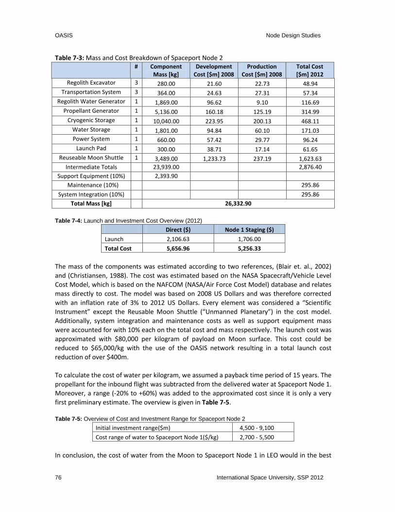
OASIS Node Design Studies
76 International Space University, SSP 2012
Table 7-3: Mass and Cost Breakdown of Spaceport Node 2
# Component Mass [kg]
Development Cost [$m] 2008
Production Cost [$m] 2008
Total Cost [$m] 2012
Regolith Excavator 3 280.00 21.60 22.73 48.94
Transportation System 3 364.00 24.63 27.31 57.34
Regolith Water Generator 1 1,869.00 96.62 9.10 116.69
Propellant Generator 1 5,136.00 160.18 125.19 314.99
Cryogenic Storage 1 10,040.00 223.95 200.13 468.11
Water Storage 1 1,801.00 94.84 60.10 171.03
Power System 1 660.00 57.42 29.77 96.24
Launch Pad 1 300.00 38.71 17.14 61.65
Reuseable Moon Shuttle 1 3,489.00 1,233.73 237.19 1,623.63
Intermediate Totals 23,939.00 2,876.40
Support Equipment (10%) 2,393.90 Maintenance (10%) 295.86
System Integration (10%) 295.86
Total Mass [kg] 26,332.90
Table 7-4: Launch and Investment Cost Overview (2012)
Direct ($) Node 1 Staging ($)
Launch 2,106.63 1,706.00
Total Cost 5,656.96 5,256.33
The mass of the components was estimated according to two references, (Blair et. al., 2002)
and (Christiansen, 1988). The cost was estimated based on the NASA Spacecraft/Vehicle Level
Cost Model, which is based on the NAFCOM (NASA/Air Force Cost Model) database and relates
mass directly to cost. The model was based on 2008 US Dollars and was therefore corrected
with an inflation rate of 3% to 2012 US Dollars. Every element was considered a “Scientific
Instrument” except the Reusable Moon Shuttle (“Unmanned Planetary”) in the cost model.
Additionally, system integration and maintenance costs as well as support equipment mass
were accounted for with 10% each on the total cost and mass respectively. The launch cost was
approximated with $80,000 per kilogram of payload on Moon surface. This cost could be
reduced to $65,000/kg with the use of the OASIS network resulting in a total launch cost
reduction of over $400m.
To calculate the cost of water per kilogram, we assumed a payback time period of 15 years. The
propellant for the inbound flight was subtracted from the delivered water at Spaceport Node 1.
Moreover, a range (-20% to +60%) was added to the approximated cost since it is only a very
first preliminary estimate. The overview is given in Table 7-5.
Table 7-5: Overview of Cost and Investment Range for Spaceport Node 2
Initial investment range($m) 4,500 - 9,100
Cost range of water to Spaceport Node 1($/kg) 2,700 - 5,500
In conclusion, the cost of water from the Moon to Spaceport Node 1 in LEO would in the best

OASIS Node Design Studies
International Space University, SSP 2012 77
case reduce the cost for the GEO business case. Despite this uncertainty, in all cases, it enables
increased payload capability to targets beyond the Moon and in general shows the advantage
of using lunar resources. Also the cost to deliver payload mass to the Moon’s surface is reduced
roughly by $15,000/kg with the use of Spaceport Node 1.
7.6 Summary and Conclusion
The OASIS tug servicer will be a reliable, simple and efficient solution for the GEO satellite
market. Together with the primary function of orbital transfer, OASIS provides all the additional
services we mentioned before. The market is both diverse and long-lasting. The primary
advantage of this solution is reliability: a standard water tank, an electrolyzer, cryogenic tanks,
robotic arm, standard interfaces, and automatic docking system are all flight proven
technologies with heritage and high TRL levels. For this reason the OASIS implementation
strategy has high confidence in an immediate initiation period, and qualification test. These
developed technologies provide our customers and their missions with an affordable and
reliable system. The execution of the mission then is a classical Hohmann transfer free from
orbital complexity. In closing, the modular design can be upgraded and sized according to
demand or request for additional services.
Figure 7-2: Upgraded Spaceport Node 1

OASIS Mission Study
78 International Space University, SSP 2012
8 MISSION STUDY
This chapter presents concepts of operations for the network of spaceports as an “existence
proof” for the viability of the OASIS network. It starts by presenting a comparison of different
options to launch a heavy payload to GTO and ends with an example mission that would use
the network of spaceports for a trip to Mars.
8.1 Options Analysis for Mission to GTO
This section presents a case study to evaluate the proposed concept for the spaceport network
from an operations point of view. The market study presented in chapter 3 has identified a
great business opportunity in offering tugging services to communication satellites from LEO to
GEO. To evaluate the team’s concept of operations in this market, the chapter presents a case
study that confronts three options to place a heavy payload into GEO.
“Bat charts” will be presented to provide an overview of the operational steps involved in each
of the three options. A bat chart is a graphical depiction of elements of a mission deploying
over time from a point of origin at the bottom, to staging points vertically on the graph, and
then to a final destination at the top of the graph, with the elements hanging from the top like
bats on a ceiling. The elements may return to the point of origin depending on the mission.
The chapter starts by presenting the current baseline option to put a very large 9,000kg
communication satellite, or two smaller 4,500kg satellites into GTO, using conventional
chemical propulsion rocket launch systems. It then confronts this solution with the proposed
concept of providing propellant and tugging capabilities from LEO to GTO. Two scenarios are
presented that use this strategy. In the first, the team evaluated a mission where Spaceport
Node 0 (KSC spaceport on the Earth’s surface) resupplies Spaceport Node 1 in LEO. The tug and
spaceport elements represent the capabilities that would be available in the first phase of the
proposed roadmap (see section 5.4.5). The last scenario corresponds to the second phase of
the roadmap by resupplying the node in LEO using resources from the Moon.
It should be noted that, even though the options presented in this chapter are all for a mission
to GTO, the spaceport network could offer the capability to place 9,000kg all the way into GEO
orbit. This would mean that the satellite does not need to carry its own propulsion system for
the final circularization and positioning burns. The fundamental design of the satellite can be
advantageously changed, to take advantage of the reduced on board propulsion functionality.
8.1.1 Baseline – Launch to GTO, Transfer to GEO
The baseline of this study is to put a 9 ton payload (or two 4.5mt payloads) directly into GTO.
The spacecraft then propels itself from GTO into its final destination in GEO. Considering the
current launching market (Arianespace, 2011), Ariane V is the cheapest launcher able to carry

OASIS Mission Study
International Space University, SSP 2012 79
out such a mission. However, since SpaceX projects that the Falcon 9 Heavy is to be completed
by 2013, we are assuming that this launcher will also be available.
The projected cost of the Falcon 9 Heavy would make it the most competitive and therefore
the optimal example for this baseline. However, since this has not yet been tested, the team
has chosen the Ariane V as the baseline launcher.
8.1.2 Alternative Scenarios Using Spaceports
8.1.2.1 Earth-supplied Spaceport in LEO
As described in Chapter 5, in the first concept of operations for the Spaceport Node 1
spaceport is, a tug service is offered from LEO to GTO. With this service, we can reduce the
amount of propellant needed during the launch phases or, equivalently, increase the mass of
the satellite to be delivered.
The bat chart below presents the mission concept of operations.
Figure 8-1: Bat Chart of a Mission with Water Supply from Earth. Legend: 1- Launch of water to LEO; 2 -Tug docks with water tank and takes it to depot; 3 -Water is transferred to main water tank and small water tank is de-orbited; 4 -Water is converted to cryogenic propellant and transferred to the tug; 5 -Launch of satellite from Earth’s surface to LEO; 6 -Tug rendezvous and docks with satellite; 7 -Tug takes satellite to GTO; 8 -Satellite is placed in GTO; 9 - Tug returns to LEO; 10 - Tug docks with depot and another mission is ready to start.

OASIS Mission Study
80 International Space University, SSP 2012
The following steps are detailed in the bat chart:
1. A Falcon 9 loaded with a full water tank launches from Earth surface to Spaceport Node
1 at LEO
2. Falcon 9 delivers the tank in orbit
This is a specific orbit close to the Spaceport Node 1
3. Tug rendezvous and docks with the orbiting tank
4. Tug transports and docks the tank to the spaceport
5. Water transfers from tank to port’s water tanks
6. Tug undocks from port and deorbits the tank
7. Steps 1 to 6 are repeated until there’s enough water on Spaceport Node 1 to perform
the desired mission
Initial propellant in the tug should be enough to perform the necessary rendezvous
and docking/undocking operations
8. Produce cryo-propellant while waiting for customer
The system uses electrolysis to convert water into LO2 and LH2. This process may
take up to 2 months and should be completed in advance of the payload arrival.
9. Launch communication satellite from Earth with Falcon 9
Launch vehicle places satellite into spaceport orbit
10. Load propellant onto tug
This process starts after the confirmation of the launch described in step 9
11. Rendezvous and docking of tug with satellite
12. Delivery of satellite to GTO (or GEO if requested by the customer)
Tug uses its own propulsion to put the satellite into its final orbit
13. Tug returns to spaceport orbit
Tug burns its last amount of fuel to return to LEO orbit. Tug uses aero-braking
system to save propellant in this maneuver
14. Rendezvous and docking of “empty” tug with spaceport
Mission complete! Loop may be repeated
The major advantage in using the tug service described in this folder instead of launching the
satellite directly into GTO is that the tug takes up the role of the upper stage of the launcher.
This reduces the mass of the launcher, allowing for a larger payload to be carried to GTO or for
the use of a smaller launcher.
8.1.2.2 The Moon-supplied Spaceport in LEO
Another scenario for supplying Spaceport Node 1 with water is to have it coming directly from the Moon to further reduce costs. This occurs in the second phase of the roadmap. The difference between the Earth-supplied and Moon-supplied scenarios is in the first three steps of the Figure 8-1. In this case, instead of launching water from the Earth to LEO, the tug brings water from the Moon. The bat chart below describes this first phase.

OASIS Mission Study
International Space University, SSP 2012 81
Figure 8-2: Bat Chart of a Mission with Water Supply from the Moon. Legend: 1 - Moon shuttle takes off from Moon surface and docks in LLO with standing-by tug to deliver water; 2- Moon shuttle returns to Moon surface after unloading its water tank (this step is repeated until the water tank transported by the tug is full) ; 3 - Moon shuttle takes off from the Moon surface and docks in LLO with standing-by tug to deliver propellant; 4- Moon shuttle returns to Moon surface after unloading the propellant tank (this step is repeated until the tug’s propellant tank is full) ; 5 – Tug transports full water tank to LEO; 6 – Tug rendezvous and docks water tank with depot in LEO; 7 – Tug rendezvous and docks with depot; 8 – Water is converted to cryogenic propellant and transferred to the tug; 9 – Launch of satellite from Earth’s surface to LEO; 10 – Tug rendezvous and docks with satellite ; 11 – Tug takes satellite to GTO; 12 – Satellite is placed in GTO; 13 – Tug returns to LEO; 14 – Tug docks with depot and stands by for another mission.
The following presents a more detailed explanation of the bat chart steps that have to do with
refueling from the Moon:
1. Tug carrying an empty Mobile Water Tank (MWT) is standing by on LLO
Spaceport Node 1 sends this tank to LLO for refilling with water from the Moon
This tank has a capacity for 30 tons of water, which is the amount necessary for
accomplishing a full tug servicing mission to GEO
2. Moon shuttle launches from lunar spaceport with a full Small Water Tank (SWT)
3. Moon shuttle rendezvous and docks with the MWT
4. SWT transfers its water to MWT
5. Moon shuttle undocks from MWT
6. Moon shuttle returns to lunar spaceport with an empty SWT
7. Robotic moon rover transports empty SWT to the storage facility

OASIS Mission Study
82 International Space University, SSP 2012
8. Moon rover transports a full SWT from the storage facility and loads it to the moon
shuttle
9. Refueling of shuttle
Small propellant generator produces propellant to refuel moon shuttle
10. Steps 2 to 9 are repeated until MWT is full
6 cycles
11. Moon shuttle launches from lunar spaceport with a full Cryogenic Propellant Tank
(CPT)
12. Moon shuttle rendezvous and docks with the tug in LLO
13. CPT transfers its propellant to tug
14. Moon shuttle undocks from tug
15. Moon shuttle returns to lunar spaceport with an empty CPT
16. Robotic moon rover transports empty CPT to the storage facility
17. Moon rover transports a full CPT from the storage facility and loads it to the moon
shuttle
18. Refueling of shuttle
Small propellant generator produces propellant to refuel moon shuttle
19. Steps 11 to 18 are repeated until tug has enough propellant for return trip to LEO
6 cycles
20. Transportation of water to Spaceport Node 1 in LEO
21. Rendezvous and docking of tank with spaceport
The used tanks can be re-used
22. Produce cryo-propellant while waiting for customer
The system uses electrolysis to convert water into LO2 and LH2. This process
may take up to three weeks and should be completed in advance of payload
arrival
Given the long process of scheduling and the tendency for propellant boil-off in
the tug’s tanks, cryo-propellant production starts only after scheduling and
confirming a customer
23. Launch communication satellite from Earth with Falcon 9
Launch vehicle places satellite into spaceport orbit
24. Load propellant onto tug
This process starts after the confirmation of the launch described in step 24
25. Rendezvous and docking of filled tug with satellite
26. Delivery of satellite to GTO (or GEO if requested by the customer)
Tug uses its own propulsion to put the satellite into its final orbit
27. Tug returns to spaceport orbit
Tug burns its last amount of fuel to return to LEO orbit. Tug uses aero-braking
system to save propellant in this maneuver
28. Rendezvous and docking of “empty” tug with spaceport
Mission complete! Loop may be repeated
29. Docking of tug with spaceport interface
The tug stays in standby for the next mission
An important advantage of sourcing water from the Moon instead of the Earth is that, even

OASIS Mission Study
International Space University, SSP 2012 83
though the Moon is further away from LEO, the velocity variation ( that is needed to reach this
orbit is significantly lower than that needed to reach it from Earth’s surface. Furthermore, by
using this option, the mission does not require the use of expendable launchers to bring water
from Earth’s surface. Instead, the team proposes the use of reusable shuttles between the
Moon surface and LLO. This saves a major portion of the operational costs of the mission. More
details can be found in Section 7.5
8.1.3 Discussion
This section presented a baseline case and two improved concepts of operations which
analyzed and compared three different options to send a satellite to GTO. These options were
analyzed from a purely operational point of view, disregarding the initial investments needed
to develop and build the infrastructure, for the sake of quantifying the operational savings for
each customer in this new market. For each of these improved concepts of operations options,
the report presents the different steps needed to complete a full mission and exemplifies a
possible way of using the architecture proposed in this report.
Note that the greatest cost associated with sourcing propellant from the Moon is the initial
cost of building the moon spaceport. However, since this chapter focuses on the mission, the
team presents only operational costs.
The process presented for each option proves that a credible concept for the mission has been
depicted that has the potential capability of bringing the overall operational costs down.
8.2 Mission to Mars
Using the OASIS network, including both LEO and Lunar resupply, a feasibility mission to Mars
designated Caravan 1 (C1) was analyzed. The 10 tons robotic mission docks to a Tug Servicer #1
provided at Node 1 in Low Earth Orbit (LEO) and transfers into the Mars Transfer Orbit (MTO).
This maneuver requires all the propellant aboard the tug to provide the necessary ∆v. The Tug
Servicer #1 is then separated and is returned to LEO using its electric ion engines for reuse.
Well in advance of launching C1, the electric ion engines aboard the advanced version of the
Tug Servicer #2 provide the velocity required to match C1 MTO velocity from LLO (Low Lunar
Orbit), and a rendezvous with C1 not far from the Moon. These propellants are generated and
supplied using the Spaceport Node 2 Lunar facilities and accompanying Moon Shuttle.
The technical feasibility of these deep space docking maneuvers has been demonstrated with
increased frequency in actual missions. (Wertz and Bell, 2003) state that intercept missions
with resolutions of under 10km is now a flight proven technology. Accordingly, the paper by
(Haeberle, Spencer and Ely, 2004) provides confidence that the tug servicer attains required
position measurements en route to Mars. The paper (You, Tung-Hang et al., 2007) provides

OASIS Mission Study
84 International Space University, SSP 2012
several experimental numbers illustrating positioning accuracy for missions to Mars using the
DSN network.
Once mated with C1, the Tug Servicer #2 initiates a boost maneuver, reducing the time of flight
to Mars from 258 days (standard Hohmann transfer) to 162 days via a staged Trans-Mars
Injection (TMI). On-orbit staging could reduce the inbound flight duration through multiple pre-
positioned stages even to 120 days as shown in (Folta, 2012). Improved flight time helps
decrease radiation exposure, required consumables and energy storage requirements for
human missions significantly. Robotic missions would rather benefit from the increased
payload mass, which could enable e.g. a Mars sample return mission.
Using Martian atmospheric braking and the remaining propellant aboard the Tug Servicer #2,
C1 circularizes about Mars and enters a coincident orbit with Phobos via a minor Hohmann
transfer.
Using the propellant provided at Spaceport Node 3 at Phobos, the Tug Servicer #2 is refueled
with cryogenic propellants. The source of the water for propellant production at Phobos is
considered to be a wet asteroid (e.g. Ceres) after proper phasing as well as water content have
been identified. A descent to the Martian surface from Mars Polar Orbit (MPO) can be initiated,
with the help of aerobraking and several retro burn maneuvers. With the availability of
propellant at Phobos, the payload mass to Mars surface could be increased.
The C1 mission analysis illustrates the phase 3 enabled OASIS networks’ ability to directly meet
the needs of the Global Exploration Roadmap, as well as offer enhanced value to any space
mission leaving the near-Earth environment. Using the same network, a return mission can be
facilitated using propellants from the same nodes in the OASIS network. Additional propellant
tanks can be added to any mission to further reduce flight durations. The standardized tank
design and flexibility of the network offers unparalleled freedom and access to space.

OASIS Mission Study
International Space University, SSP 2012 85
Figure 8-3: Schematic of Example Mars Mission
Mars
Phobos
Node3
Launch toNode 1
Low EarthOrbit
Node 1
Node0
Node0
Moon
Node2
10T S/C
Tug 1
Tug 2
Tug 2
10T S/C
2.2
km/s
Tran
s-M
ars
inje
ctio
n
Tug 1
10
T S/
C
4.3 km/s
Boost into MTO
10T S/C
2.2 km/s
Phobos Orbit
Insertion
Tug 2 10T S/C
Refuel at Node 3
Tug 2
10T S/C
Mars Orbit a
nd Deceleration
Wet asteroid (e.g. Ceres)
Supply of Water
Tug 2

OASIS Conclusion
86 International Space University, SSP 2012
9 CONCLUSION
The International Space Exploration Coordination Group outlines Mars in its Global Exploration
Roadmap as the ultimate near-future goal in human exploration of the Solar System. While a
strong case exists for the exploration of the Solar System, in particular the Moon and Mars, few
organizations have adequate financial resources to take advantage of the economic
possibilities. The high cost of space exploration means that only government supported
organizations have conducted most of the missions to date. The primary contributing factor to
the high cost of space exploration is launch vehicle costs and subsequent space transportation
costs and logistics; this poses a substantial barrier to any enterprise. However, the continually
decreasing cost of technology, new mission architecture solutions, and the economic potential
held in the natural resources of the Solar System enables the pursuit of space transportation
and exploration as a new core business to benefit humanity.
The proposed solution is OASIS, a network of spaceports extending existing transportation and
logistics infrastructure on Earth into space. This network has the objective of reducing the
overall cost of space exploration and creating a vibrant commercial space market. The primary
nodes of the network consist of LEO, the Moon, and the Mars moon, Phobos, corresponding to
the short- (2012-2025), medium- (2025-2045), and long- (2045–onwards) term capabilities of
the network, respectively.
In the short-term, the first node of the spaceport network is to be established in LEO,
addressing a mature current market. As a result, the primary services provided in LEO consist of
on orbit-refueling and a ‘tug’ service from LEO to GEO. The ‘tug’ service is the initial source of
business in order to make the overall network economically viable in the long run. The lunar
surface is the second spaceport node in the network; it will supply the LEO node with high
specific impulse (LO2 and LH2) propellant mined and extracted from lunar regolith and/or water
ice. Using resources from the Moon could drastically reduce the costs of propellant in LEO and
ensure a strong and enabling business case for the network. It is also an important stepping
stone to traveling throughout the Solar System and the development of Spaceport Node 3 on
Phobos. The Martian surface and Phobos have been identified as important goals of space
exploration for many space agencies. Compared to the direct route to Mars, the low
gravitational field of Phobos (or Deimos) facilitates easy access to the Martian surface and
further celestial objects via staging with the use of ISRU water derived propellants.
To facilitate the feasibility of OASIS, international cooperation is kept as a major driver of the
project. For this reason, an international governing authority is established for the network of
spaceports, named the "International Spaceport Authority". The members of this organization
could be compromised of the 14 ISECG member states and other willing nations. To carry out
the development of OASIS, ISPA will contract a private, transnational company designated as
“the Spaceport Company” to manage and operate the network. The legal, political, and societal
framework for the SPC’s operations has been identified and outlined in detail.
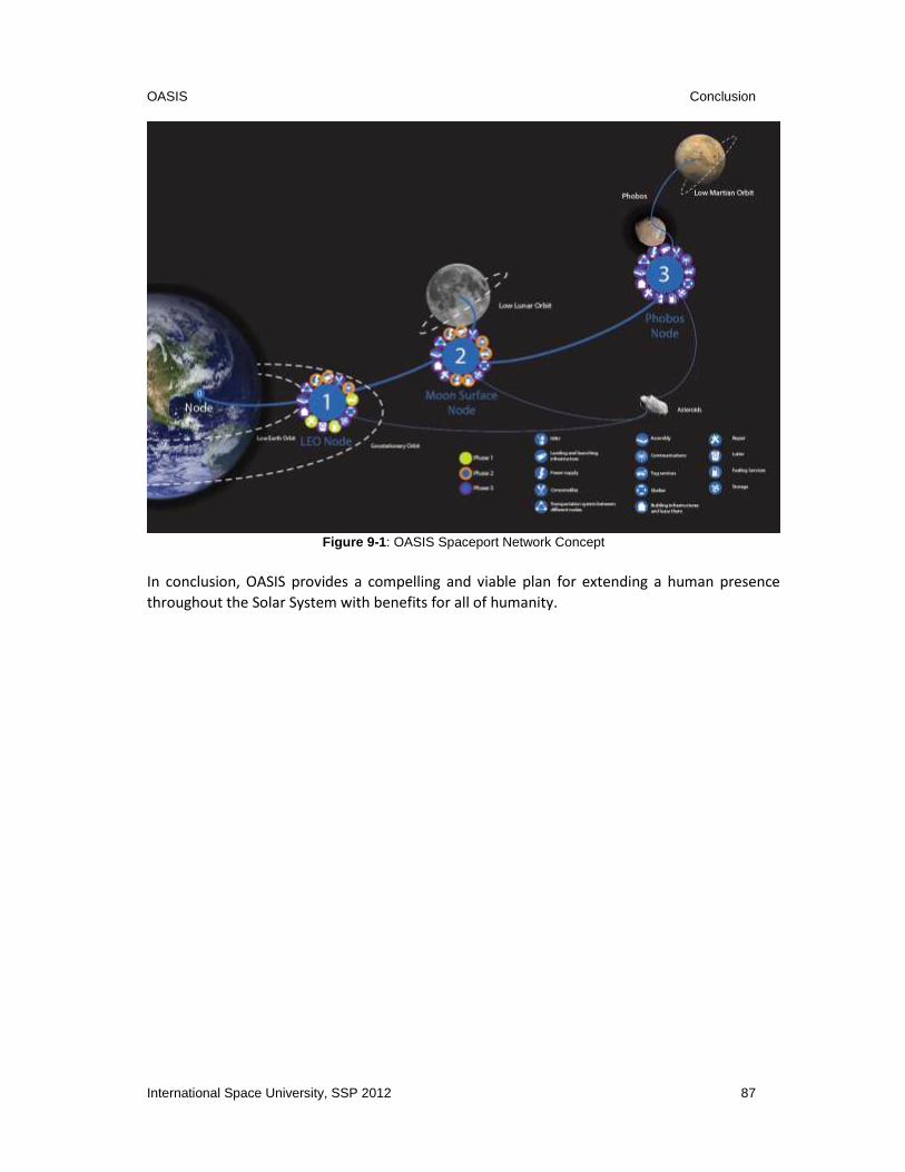
OASIS Conclusion
International Space University, SSP 2012 87
Figure 9-1: OASIS Spaceport Network Concept
In conclusion, OASIS provides a compelling and viable plan for extending a human presence
throughout the Solar System with benefits for all of humanity.

OASIS References
88 International Space University, SSP 2012
10 REFERENCES
Adler, A. et al., 2003. AFRL PowerSail Structure For Large Solar Arrays. In: AIAA 2003-6356. Long
Beach, CA, 23-25 September 2003.
Andreas, E.L., 2007. New estimates for the sublimation rate for ice on the Moon. Icarus, 186(1),
pp.24–30.
Arianespace, 2011. Ariane 5 User’s Manual. Evry-Courcouronnes Cedex: Arianespace
ASD-EUROSPACE, 2012. Space Trends - Global Space Activity Overview 1986-2011. ASD-
EUROSPACE. [online] Available from:
<http://www.eurospace.o/Data/Sites/1/pdf/spacetrends/eurospacespacetrends2011.pdf >
[Accessed 10 July 2012]
Badescu, V., 2010. Mars: Prospective Energy and Material Resources. Berlin Heidelberg:
Springer.
Badescu, V., 2012. Natural Resources of the Moon and Legal Regulation. Dordrecht Heidelberg
London New York: Springer.
Beasley, D., Hendrix, S., Weaver, D., 2005. Largest Asteroid May Be “Mini Planet” with Water
Ice. Hubblesite. NASA Headquarters. [online] Available from:
<http://hubblesite.org/newscenter/archive/releases/2005/27/text/>. [Accessed July 31 2012]
Bienhoff, D. 2010. LEO Propellant Depot : Servicing Impact on Space Missions. NASA GSFC
International Servicing Workshop. March 24-26 2010.
Blair, B.R. et al., 2002. Space Resource Economic Analysis Toolkit: The Case for Commercial
Lunar Ice Mining, Final Report to the NASA Exploration Team.
Broniatowski, D.A., Faith, G.R., Sabathier, V.G. (2006) The Case for Managed International
Cooperation in Space Exploration. Center for Strategic and International Studies.
Broyles, B., 1991. Origin of Apollo 13 quote: "Failure is not an option." Available from: <http://www.spaceacts.com/notanoption.htm> [Accessed 18 July 2012]. Bussey, B., Plescia, J., Spudis, P., 2006. The Strategic Value of RLEP Lunar Polar Exploration. Spudis Lunar Resources. Applied Physics Laboratory. [online] Available from: <http://www.spudislunarresources.com/Papers/Lunar robotics polar white paper

OASIS References
International Space University, SSP 2012 89
04_19_06.htm.> [Accessed July 31 2012]
Carruba, V., Coradini, A., 1999, Lunar Cold Traps: Effects of Double Shielding. Icarus, 142, 402-
413.
China Great Wall Industry Corporation, 2011. Long March 3A Series Launch Vehicle User’s
Manual Issue 2011. [online] Available from:
<http://cn.cgwic.com/LaunchServices/Download/manual/index.html> [Accessed 18 July 2012]
Christiansen, E.L., et al. , 1988. Conceptual Design of a Lunar Oxygen Pilot Plant, NAS9-17878,
EEI Report No. 88-182, Eagle Engineering Inc., Houston, Texas.
Christol, C., 1984. Modern international law of outer space. New York: Pergamon Press.
Clement, G. (2012a). Life Support Systems during Space missions. Melbourne, FL/International
Space University June 2012
Clement, G. (2012b). Extra Vehicular Activities. Melbourne, FL/International Space University
June 2012
Cohen, M., 1998. Space Habitat Design Integration Issues. SAE Technical, doi: 10.4271/981800
Condon, G.L., Wilson, S. 2002. Earth to Moon transfers: Direct vs. via Libration Points (L1, L2).
Johnson Space Center. 9 October 2002.
Covault, C., 2012. First Look: China’s Big New Rockets. Americaspace. [online] Available from:
<http://www.americaspace.org/?p=22881>. [Accessed July 31 2012]
Curreri, P. A., 2006. Process Demonstration for Lunar In Situ Resource Utilization—Molten Oxide Electrolysis. [online] Available from: <http://ntrs.nasa.gov/archive/nasa/casi.ntrs.nasa.gov/20070018263_2007017478.pdf> [Accessed 31 July, 2012]
Dator, J., 2012. Cultural Rationale for Space Activities. Melbourne, FL/International Space
University. 14 June 2012.
Davis, L.T., 2008. Spaceport SWOT An Analysis of Strengths , Weaknesses , Opportunities , and
Threats for Selected Spaceports Around the World. Thesis (M.Sc.). International Space
University
Dino, J., 2009. LCROSS Impact Finds Water on the Moon. Physorg. [online] Available from:
<http://phys.org/news177337293.html>. [Accessed July 31 2012]

OASIS References
90 International Space University, SSP 2012
Doer, D. 2012. Muscle and Bone in Space Effects of Space Flight. Melbourne, FL/International
Space University. 18th of June 2012.
Drake, B.G. (2009) Human Exploration of Mars Design Reference Architecture 5.0. National
Aeronautics and Space Administration.
Drysdale, A.E. (2001) Life Support Trade Studies Involving Plants on Environmental Systems. The
Boeing Company.
Duke, M.B., Hoffman, S.J., Snook, K. (2003) Lunar Surface Reference Missions: A Description of
Human and Robotic Surface Activities. National Aeronautics and Space Administration.
Edelstein, K. (1995) Orbital impacts and the Space Shuttle windshield. NASA JSC.
Elert, G., 2004. The Physics Factbook, Acceleration Due to Gravity on the Moon [online].
Available from: <http://hypertextbook.com/facts/2004/MichaelRobbins.shtml> [Accessed
July 22, 2012]
Elert, G., 2004. The Physics Factbook, Acceleration Due to Gravity on Mars [online].
Available From: <from http://hypertextbook.com/facts/2004/JahshirahRossi.shtml>
[Accessed July 22, 2012]
Elsig, M. (2006) Different Facets of Power in Decision-Making in the WTO. National Centres of
Competence in Research.
Unknown, 2012. Space Tug. Encyclopedia Astronautica. [online] Available from:
<http://www.astronautix.com/craft/spacetug.htm> [Accessed July 15, 2012].
Fasan, E., 1980. Some Legal Problems regarding the Moon. In Proceedings of the 23rd
Colloquium on the Law of Outer Space. AIAA.
Federal Aviation Administration, 2012. 2012 Commercial Space Transportation Forecasts.
Feldman, P.D. and A'Hearn, M.F., 1992. Water Vaporization on Ceres, Icarus, 98(1), pp.54–60.
Fikes, J.C., Howell, J.T. and Henley, M.W., 2006. Utilizing Solar Power Technologies for On-Orbit
Propellant Production. In: International Space Development Conference , 4-7 May 2006 Los
Angeles, CA.
Fink, W. et al., 2011. Robotic Test Bed for Autonomous Surface Exploration of Titan , Mars , and
Other Planetary Bodies. IEEE Aerospace Conference, 5-12 March 2011, Big Sky, MT. IEEE, pp.1–
11.

OASIS References
International Space University, SSP 2012 91
Fox, W., 2012. Timeline of Space Missions. Futuretimeline. [online] Available from:
<http://futuretimeline.net/subject/space.htm> [Accessed July 18, 2012].
Folta, Vaughan, Rawitscher, Westmeyer, 2012, Fast Mars Transfers Through On-Orbit Staging.
Concepts and Approaches for Mars Exploration
Frassanito, J., 2010. Human Exploration Beyond LEO by the End of the Decade: Designs for Long-
Duration “Gateway” Habitats. In: 15th ISU Annual International Symposium. The International
Space Station: Maximing the Return from Extended Operations, 15-17 February 2011
Strasbourg, France. NASA, pp. 1-22
FUTRON, 2002. Space Transportation Costs: Trends in Price Per Pound to Orbit. FUTRON.
Gibson, E.K., Pillinger, C.T., 2010. Re-Assessment of “Water on the Moon” after LCROSS. In:
41st Lunar and Planetary Science Conference, March 1-5 2010 The Woodlands, TX. Lunar and
Planetary Institute.
Goddard Space Flight Center, (2010). On-Orbit Satellite Servicing Study Project Report. National
Aeronautics and Space Administration.
Gorove, S., 1995. Space resources and developing nations - a legal assessment. In: Natural
Resources of the Moon and Legal Regulation. Warsaw: International Space Miscellanea, pp. 97–
103.
Government of India, 2008. EDUSAT Programme. Indian Space Research Organisation
Satcomm Applications. [online] Available from: <http://www.isro.org/scripts/sat_edusat.aspx>
[Accessed 22 July, 2012].
Griffin, M.D. 2005. NASA and the Business of Space. American Astronautical Society 52nd
Annual Conference. 15-16 November 2005.
Greicius, T., 2012. Vesta Likely Cold and Dark Enough for Ice. [online] Available from:
http://www.nasa.gov/mission_pages/dawn/news/dawn20120125.html> [Accessed July 31,
2012]
Green, J., 2012. The Space Environment. Melbourne,FL/International Space University. June
11 2012.
Haeberle, D.W., Spencer, D.B., Ely, T., 2004. Preliminary Investigation of Interplanetary
Navigation Using Large Antenna Arrays with Varied Baselines. AIAA/AAS Astrodynamics
Specialist Conference August 16-19 2004 Providence, RI.

OASIS References
92 International Space University, SSP 2012
Hamera, K. et al., 2008. An Evolvable Lunar Communication and Navigation Constellation
Concept. In: 2008 IEEE Aerospace Conference, 1-8 March 2008 Colorado. IEEE, pp.1–20.
Hamilton, D. 2012. Space Medicine. Melbourne, Florida, USA/International Space University. 27
June 2012.
Hanford, A.J. (2004) Advanced Life Support Baseline Values and Assumptions Document.
National Aeronautics and Space Administration.
Hashimoto, M., 2009. Public-Private Partnerships in Space Projects: An Analysis of Stakeholder
Dynamics. Thesis (M.Sc.). Massachusetts Institute of Technology.
Henderson, E.M., Holderman, M.L., 2011. Technology Applications that Support Space
Exploration. In: 47th AIAA/ASME/SAE/ASEE Joint Propulsion Conference, 31 Jul - 3 Aug 2011,
San Diego, CA. AIAA, pp.1–21.
Hermida, J., 2004. Legal Basis for a National Space Legislation, Dordrecht, Kluwer.
Horsham, G.A.P., Schmidt, G.R., Gilland, J.H. (2010) Establishing a Robotic , LEO-to-GEO Satellite
Servicing Infrastructure as an Economic Foundation for Exploration. National Aeronautics and
Space Administration.
International Space Station (ISS) Multilateral Coordination Board (MCB), 2011. International
Docking System Standard (IDSS) Interface Definition Document (IDD) Revision A. [online]
Available from: <http://www.internationaldockingstandard.com/> [Accessed July 31, 2012].
International Launch Services, 2009. Proton Rocket Mission Planner’s Guide. [online] Available
from: <http://www.ilslaunch.com/launch-services/proton-mission-planners-guide>. [Accessed
July 31, 2012].
International Space Exploration Coordination Group, 2010. About ISECG. ISECG. [online]
Available from: <http://www.globalspaceexploration.org/about-isecg> [Accessed July 20, 2012].
International Space Exploration Coordination Group, 2011. The Global Exploration Roadmap.
Washington D.C. USA.
ISU Team Project (2006a) Fertile Moon. International Space University.
ISU Team Project (2006b) LUNA GAIA. International Space University.
ISU Team Project (2007) Full Moon : storage & delivery of oxygen and hydrogen. International

OASIS References
International Space University, SSP 2012 93
Space University.
ISU Team Project (2008) FuturIST : future infrastructure for space transportation. International
Space University.
ISU Team Project (2009) ACCESS Mars Assessing Cave Capabilities Establishing Specific Solution.
International Space University.
ISU Team project (2011) Kourou Vision 2030, International Space University.
JAXA, 2008. Remote Manipulator System: About Kibo - Kibo Japanese Experimental Module.
[online] Available from: <http://kibo.jaxa.jp/en/about/kibo/rms/> [Accessed July 5, 2012].
JAXA, 2012. Overview of the H-IIB Launch Vehicle. [online] Available from:
<http://www.jaxa.jp/countdown/h2bf1/overview/h2b_e.html> [Accessed July 18, 2012].
Joyner, C. C., 1986. Legal Implications of the Concept of the Common Heritage of Mankind.
International and Comparative Law Quarterly, 35, pp. 190-199.
Junichiro K., et. Al., 2010, Global Space Exploration Policies and Plans: Insights from Developing
the ISECG GLOBAL Exploration Roadmap, International Astronutical Federation
Kerrest, A., 2001. Outer Space: Res Communis, Common Heritage or Common Province of
Mankind? In: Proceedings of the 10th ECSL Summer Course on Space Law and Policy, 27 August
- 8 September University of Nice, France.
Komerath, N.M., Rangedera, T., Nally, J., 2006. Space-Based Economy Valuation, Analysis, and
Refinement. In: Space 2006 Conference, San Jose, CA, pp. 1–10.
Kutter, B.F. et al., 2005. Atlas Centaur Extensibility to Long-Duration In-Space Applications. AIAA
2005-6738, pp. 1–13.
Larson, W.J., Wertz, J.R., 1999. Space Mission Analysis and Design, 3rd edition (Space
Technology Library), Microcosm.
Laurini K., Karabadzhak G., Satoh N., Hufendbah B., 2011. International Space Station (ISS)
Lessons Learned and their Influence on preparations for human exploration beyond low earth
orbit. International Astronautical Congress, 3 -7 October 2011 Cape Town, South Africa.
Lee, Y., 2006b. Registration of space objects: ESA member states’ practice. Space Policy, 22(1),
pp.42–51.

OASIS References
94 International Space University, SSP 2012
Lester, D. and Thronson, H., 2011. Low-Latency Lunar Surface Telerobotics from Earth-Moon
Libration Points. AIAA SPACE 2011 Conference 27 - 29 September 2011 Long Beach, CA. AIAA.
Lewis, J.S., 2006. Asteroid Exploration and Exploitation. In: Next Generation Exploration August
16-18 2006 California, USA.
Long, A., Richards, M., and Hastings, D., 2007. On-Orbit Servicing: A New Value Proposition for
Satellite Design and Operation, Journal of Spacecraft and Rockets, 44 (4), pp. 964-976.
Lunar Exploration Analysis Group (LEAG), (2011). The Lunar Exploration Roadmap: Exploring the
Moon in the 21st Century: Themes, Goals, Objectives, Investigations, and Priorities, 1.1, LEAG
Matte, N.M, 1977. Aerospace law: From Scientific Exploration to Commercial Utilization. In
Moon Resources of the Moon and Legal Regulation. AIAA.
McKay, C.P., Davis, W.L., 1989. Planetary protection issues in advance of human exploration of
Mars. Advances in space research. The official journal of the Committee on Space Research
(COSPAR), 9(6), pp.197–202.
McKee, M., 2005. Sunny Spot Picked Out for Future Lunar Base. [online] Available from:
<http://www.newscientist.com/article/dn7263-sunny-spot-picked-out-for-future-lunar-
base.html> [Accessed July 18, 2012].
McLean, C., 2011. Cryogenic Propellant Depots Design Concepts and Risk Reduction Activities.
Ball Aerospace and Technologies. March 2 2011.
Metzger, P.T. et al., 2010. Affordable , rapid bootstrapping of space industry and solar system
civilization. Journal of Aerospace Engineering (Preprint), pp.1–24.
Mineiro, Michael., 2012. Personal communication July 12 2012.
Mitchell, C.A., 1994, Bioregenerative life-support system. American journal of chemical
nutrition, 60(5), pp. 820-824.
Murphy, D.M., 2012. MegaFlex - The Scaling Potential of UltraFlex Technology. In: AIAA-2012-
tbd, 53rd AIAA Structures, 23-26 April: AIAA, pp.1–18.
National Aeronautics and Space Administration. 2001. Dirty Ice Snow Cones. [online] Available
from: <http://phoenix.lpl.arizona.edu/images/Mars_Full_Planet_Water_Map.jpg> [Accessed
July 21, 2012].

OASIS References
International Space University, SSP 2012 95
NASA's Science Mission Directorate, 2007. Science Plan. National Aeronautics and Space
Administration.
National Research Council (NRC), 2011. Vision and Voyages for Planetary Science in the Decade
2013-2022. Washington D.C.: The National Academies Press.
National Research Council (NRC), 2012. NASA Space Technology Roadmaps and Priorities:
Restoring NASA's Technological Edge and Paving the Way for a New Era in Space. Washington,
DC: The National Academies Press.
NEAmines Group, 2007. Orbital Tug in Low Earth Orbit: An exploration into the challenges , and
a first attempt at designing a viable construction.NEAmines Group.
Potter, S.D. et al., 2001. A Cryogenic Propellant Production Depot for Low Earth Orbit. In:
International Space Development Conference, 24-28 May 2001 Albuquerque, NM, pp. 36.
Pratt & Whitney Rocketdyne, 2012. RL10 Engine. [online] Available from:
<http://www.pw.utc.com/products/pwr/propulsion_solutions/rl10.asp> [Accessed July 15,
2012].
Pullen, L. 2009. Could Life on Earth Have Come From Ceres. [online] Available from:
<http://www.msnbc.msn.com/id/29535279/ns/technology_and_science-space/t/could-
life-earth-have-come-ceres/#.UBgghGHEK8B> [Accessed July 31, 2012]
Raftery, M. 2011. ISS Exploration Platform Concept ISS. Boeing. 15 November 2011.
Rapp, D. 2006. Mars life support systems. The Mars Journal. Volume 2, pp.72–82. [online]
Available from: <http://www.marsjournal.org/contents/2006/0005/> [Accessed July 21, 2012].
Retamozo, L. R., 2002, Reaching For Mars, NASA Marsport Design Competition .
Rivkin, A.S., Volquardsen, E.L., Clark, B.E., 2006. The Surface Composition of Ceres: Discovery of
Carbonates and Iron-rich Clays. Icarus. 185(2), pp.563–567.
Rucker, M. (2012). Issues and Design Drivers for deep Space Habitats. NASA JSC.
Ryschkewitsch, M., Schaible, D., Larson, W. (2009) The Art and Science of Systems Engineering.
Sagan C., 1994. Pale Blue Dot: A Vision of the Human Future in Space, Ballantine Books.
Saleh, J.H., Lamassoure, E., Hastings, D.E., 2002. Space systems flexibility provided by on-orbit
servicing: Part 1. Journal of spacecraft and rockets. 39(4), pp.551–560.

OASIS References
96 International Space University, SSP 2012
Sanders, G.B. et al., 2005. Results from the NASA Capability Roadmap Team for In-Situ Resource
Utilization. In: International Lunar Conference, 18-23 September 2005 Toronto, Canada.
Sanders, G.B., Larson, W.E., 2011. Development and Demonstration of Sustainable Surface
Infrastructure for Moon / Mars Missions. In: 62nd International Astronautical Congress, 5
October 2011 Cape Town, South Africa, pp. 1–30.
Sankaran, K. et al., 2004. A survey of propulsion options for cargo and piloted missions to Mars.
Annals of the New York Academy of Sciences. 1017, pp.450–67.
Scarpa, P., 2012. Future Space Health Care. Melbourne, FL/International Space University.
June 2012.
Schafer, B. K. , 1986. Solid, Hazardous, and Radioactive Wastes in Outer Space: Present Controls
and Suggested Changes. In: LAW, VALUES, AND THE ENVIRONMENT: A READER AND SELECTIVE
BIBLIOGRAPHY Scarecrow Press. Lanham, MD, pp. 395-399.
Sea Launch, 2008. Sea Launch User’s Guide. [online] Available from: <http://www.sea-
launch.com/customers_webpage/sluw/doc_src/SectionALL.pdf> [Accessed July 31, 2012]
Shi, X. et al., 2012. Working models for the gravitational field of Phobos. Science China Physics,
Mechanics and Astronomy, 55(2), pp.358–364.
Simberg, R. 2012. Economic Benefits of In-Space Propellant Delivery, Storage, Transfer and
Manufacture. Pasadena, CA. 24-25 April 2012.
Space Exploration Technologies Corporation, 2012. Falcon Heavy. [online] Available from:
<http://www.spacex.com/falcon_heavy.php> [Accessed July 18, 2012].
Spencer D. B., Haeberle, D.W., Ely, T. A., 2004. Preliminary Investigation of Interplanetary
Navigation Using Large Antenna Arrays with Varied Baselines. In: AIAA/AAS Astrodynamics
Specialist Conference and Exhibit, 16 -19 August 2004, Providence, RI.
Spudis, P.D., Lavoie, T., 2010. Mission and Implementation of an Affordable Lunar Return.
Space Manufacturing, 14, pp.1–30.
Sterns, P.M., Tennen, L., 1999. Institutional approaches to managing space resources. In: IISL
Colloquium on the Law of Outer Space, 28 September - 2 October 1998 Melbourne, Australia,
pp. 33–45.
Stott, C. 2012. Economic Rationale for Space. Melbourne, FL/International Space University. 5

OASIS References
International Space University, SSP 2012 97
June 2012.
Thomas, P.C. et al., 2005. Differentiation of the asteroid Ceres as revealed by its shape. Nature,
437(7056), pp.224–6.
Townsend, I. I. et al., 2010. Performance of Regolith Feed Systems for Analog Field Tests of
In-Situ Resource Utilization Oxygen Production Plants in Mauna Kea, Hawaii [online].
Available from:
<http://www.esmats.eu/amspapers/pastpapers/pdfs/2010/townsend.pdf> [Accessed
July 31, 2012]
Tribble, A. C., 2003. The Space Environment: Implications for Spacecraft Design. Princeton:
Princeton University Press.
United Launch Alliance, 2011a. Atlas V. [online] Available from:
<http://www.ulalaunch.com/site/pages/Products_AtlasV.shtml> [Accessed July 31, 2012].
United Launch Alliance, 2011b. Delta IV. [online] Available from:
<http://www.ulalaunch.com/site/pages/Products_DeltaIV.shtml> [Accessed July 31, 2012].
Unknown, 2005, Discovering the men and women of Discovery, CNN. [online] Available from:
<http://articles.cnn.com/2005-07-11/tech/shuttle.crew_1_charles-camarda-veteran-of-three-
space-discovery-mission?_s=PM%3ATECH/> [Accessed July 31, 2012].
USLEGAL, 2012. Port Authority Law & Legal Definition. [online] Available from:
<http://definitions.uslegal.com/p/port-authority/> [Accessed July 20, 2012].
United Nations, 1979. Moon Agreement.
United Nations, Treaty on Principles Governing the Activities of States in the Exploration and
Use of Outer Space, including the Moon and Other Celestial Bodies; 610 United Nations Treaty
Series 205 (opened for signature 27 January 1967.), 610 UNTS 205 referred to as the Outer
Space Treaty (OST) 1967.
United Nations Office for Outer Space Affairs, 2006. OOSA - Treaty Database. [online] Available
from: <http://www.oosa.unvienna.org/oosatdb/showTreatySignatures.do> [Accessed July 20,
2006]
University of Arizona, 2008. HiRISE. [online] Available from:
<http://hirise.lpl.arizona.edu/phobos.php> [accessed: July 24, 2012]
Viikari, L., 2012. Natural Resources of the Moon and Legal Regulation. In: Badescu, V. Moon:

OASIS References
98 International Space University, SSP 2012
Prospective Energy and Material Resources.
Wells, R.N., 1996, Law, Values, and the Environment , London, The Scarecrow Press, Inc.
Wertz, J., Bell R., 2003. Autonomous rendezvous and docking technologies—status and
prospects. SPIE’s 17th Annual International Symposium on Aerospace/Defense Sensing,
Simulation, and Controls, 21-25 April Orlando, USA.
Wheeler, R.M., 2004. Horticulture for Mars 1. In: XXVI International Horticultural Congress:
Horticulture, Art and Science for Life - The Colloquia Presentations, 30 October 2004 Toronto,
Canada, pp.201–215.
White, F., 1998. The Overview Effect: Space Exploration and Human Evolution, Second Edition
(Library of Flight Series). 2nd ed. Reston, VA: American Institute of Aeronautics and
Astronautics.
Williams, D.R., 2004. Asteroid Fact Sheet. [online] Available from:
<http://nssdc.gsfc.nasa.gov/planetary/factsheet/asteroidfact.html> [Accessed July 18,
2012].
Williams, D.R., 2010a. Mars Fact Sheet. [online] Available from:
<http://nssdc.gsfc.nasa.gov/planetary/factsheet/marsfact.html> [Accessed July 18, 2012].
Williams, D.R., 2010b. Moon Fact Sheet. [online] Available from:
<http://nssdc.gsfc.nasa.gov/planetary/factsheet/moonfact.html> [Accessed July 18, 2012].
You, T.H. et al., 2007. Navigating Mars Reconnaissance Orbiter Launch Through Primary Science
Orbit. AIAA SPACE 2007 Conference & Exposition, 18-20 September Long Beach, California.
Zegler, F., Kutter, B., 2010. Evolving to a Depot-Based Space Transportation Architecture. In:
American Institute of Aeronautics and Astronautics SPACE 2010 Conference and Exposition, 30
August - 2 September Anaheim, CA, pp.1–14.
Zolotov, M.Y., 2009. On the composition and differentiation of Ceres. Icarus, 204(1), pp.183–
193.
Zubrin, R. et al. (2010) Mars Regolith Water Extractor. National Aeronautics and Space
Administration. Report number: 10-1 X1.01-8174

OASIS Appendix
International Space University, SSP 2012 99
11 APPENDIX
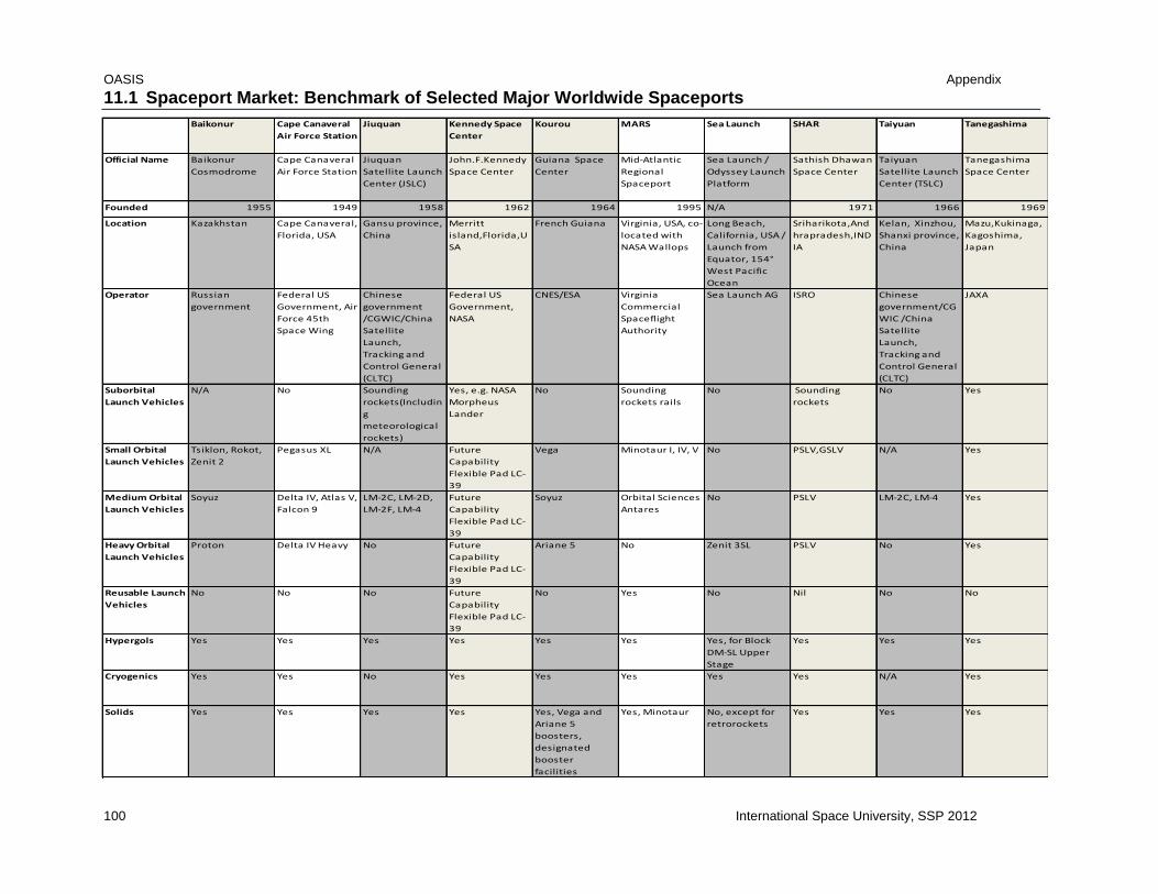
OASIS Appendix
100 International Space University, SSP 2012
11.1 Spaceport Market: Benchmark of Selected Major Worldwide Spaceports
Baikonur Cape Canaveral
Air Force Station
Jiuquan Kennedy Space
Center
Kourou MARS Sea Launch SHAR Taiyuan Tanegashima
Official Name Baikonur
Cosmodrome
Cape Canaveral
Air Force Station
Jiuquan
Satellite Launch
Center (JSLC)
John.F.Kennedy
Space Center
Guiana Space
Center
Mid-Atlantic
Regional
Spaceport
Sea Launch /
Odyssey Launch
Platform
Sathish Dhawan
Space Center
Taiyuan
Satellite Launch
Center (TSLC)
Tanegashima
Space Center
Founded 1955 1949 1958 1962 1964 1995 N/A 1971 1966 1969
Location Kazakhstan Cape Canaveral,
Florida, USA
Gansu province,
China
Merritt
island,Florida,U
SA
French Guiana Virginia, USA, co-
located with
NASA Wallops
Long Beach,
California, USA /
Launch from
Equator, 154°
West Pacific
Ocean
Sriharikota,And
hrapradesh,IND
IA
Kelan, Xinzhou,
Shanxi province,
China
Mazu,Kukinaga,
Kagoshima,
Japan
Operator Russian
government
Federal US
Government, Air
Force 45th
Space Wing
Chinese
government
/CGWIC/China
Satellite
Launch,
Tracking and
Control General
(CLTC)
Federal US
Government,
NASA
CNES/ESA Virginia
Commercial
Spaceflight
Authority
Sea Launch AG ISRO Chinese
government/CG
WIC /China
Satellite
Launch,
Tracking and
Control General
(CLTC)
JAXA
Suborbital
Launch Vehicles
N/A No Sounding
rockets(Includin
g
meteorological
rockets)
Yes, e.g. NASA
Morpheus
Lander
No Sounding
rockets rails
No Sounding
rockets
No Yes
Small Orbital
Launch Vehicles
Tsiklon, Rokot,
Zenit 2
Pegasus XL N/A Future
Capability
Flexible Pad LC-
39
Vega Minotaur I, IV, V No PSLV,GSLV N/A Yes
Medium Orbital
Launch Vehicles
Soyuz Delta IV, Atlas V,
Falcon 9
LM-2C, LM-2D,
LM-2F, LM-4
Future
Capability
Flexible Pad LC-
39
Soyuz Orbital Sciences
Antares
No PSLV LM-2C, LM-4 Yes
Heavy Orbital
Launch Vehicles
Proton Delta IV Heavy No Future
Capability
Flexible Pad LC-
39
Ariane 5 No Zenit 3SL PSLV No Yes
Reusable Launch
Vehicles
No No No Future
Capability
Flexible Pad LC-
39
No Yes No Nil No No
Hypergols Yes Yes Yes Yes Yes Yes Yes, for Block
DM-SL Upper
Stage
Yes Yes Yes
Cryogenics Yes Yes No Yes Yes Yes Yes Yes N/A Yes
Solids Yes Yes Yes Yes Yes, Vega and
Ariane 5
boosters,
designated
booster
facilities
Yes, Minotaur No, except for
retrorockets
Yes Yes Yes

OASIS Appendix
International Space University, SSP 2012 101
Baikonur Cape Canaveral
Air Force Station
Jiuquan Kennedy Space
Center
Kourou MARS Sea Launch SHAR Taiyuan Tanegashima
Propellant
Storage
Yes Yes Yes Yes Yes Liquid fueling
facilty
Yes, LOX and
kerosene
Yes Yes Yes
Propellant
Production
Oxygen Yes N/A No Yes, liquid
cryogenic and
solid
N/A No Yes N/A Yes
Clean Rooms Yes Yes Yes Yes Class 100,000 Class 100,000 Yes N/A Yes
Mission Control Yes Operations
Control Center
Mission
Command and
Control Center
Yes Mission Control
Center
Launch Control
Center on
Assembly and
Command Ship
Yes N/A Yes
Possible
Trajectories
East not
possible
(China),
Retrograde
Orbits,
East LEO, MEO, HEO East GTO, LEO wide
variety of orbits
and inclinations
possible
Inclination
between 38 and
60 degrees, sun-
synchronous
case-by-case
GTO preferred,
wide variety of
inclinations
possible
East and west LEO, Sun-
synchronous
Westward
Latitude
(Minimum
Inclination)
45°55' N 28° N 41° N 28° N 5°14' N 38° 0° 14° N 38°50' N 30° N
Runways Two airports Yes Dingxin Airport,
4100 m, 75 km
from launch site
Shuttle Landing
Facility
Yes,
Rochambeau
3200 m, 75 km
distance
Wallops Flight
Facility Airport
No dedicated
ones, but
transport to
regional
airports can be
facilitated
No Taoyuan Airport No
Ports No Close to Port
Canaveral
No Yes Yes, Pariacabo
Docking Area,
9km
distance,Cayen
ne harbour, 85
km distance
N/A Yes, Sea Launch
Home Port in
Long Beach
No No No
Rail Connections Yes Yes Yes Yes No No No No Yes Yes
Road
Connections
Yes Yes Yes Yes Only one two-
lane road to
next bigger city
of Cayenne
Yes Yes, but only to
on-land
integration
facilities
Yes Yes Yes
Human
Spaceflight
Yes, Soyuz No Yes, on LM-2F /
Shenzhou
Yes No No taxation for
related
activities
No No No No
Space Tourism Yes, Space
Adventures Inc.
No No Yes No No No No No
Commercial
Launches
Yes Yes, on FAA
licensed
vehicles
Yes Yes Yes,
Arianespace
Yes Yes Yes Yes No
Telemetry and
Tracking
Yes Yes Yes Yes Yes On-site and
downrange
Yes Yes Yes Yes
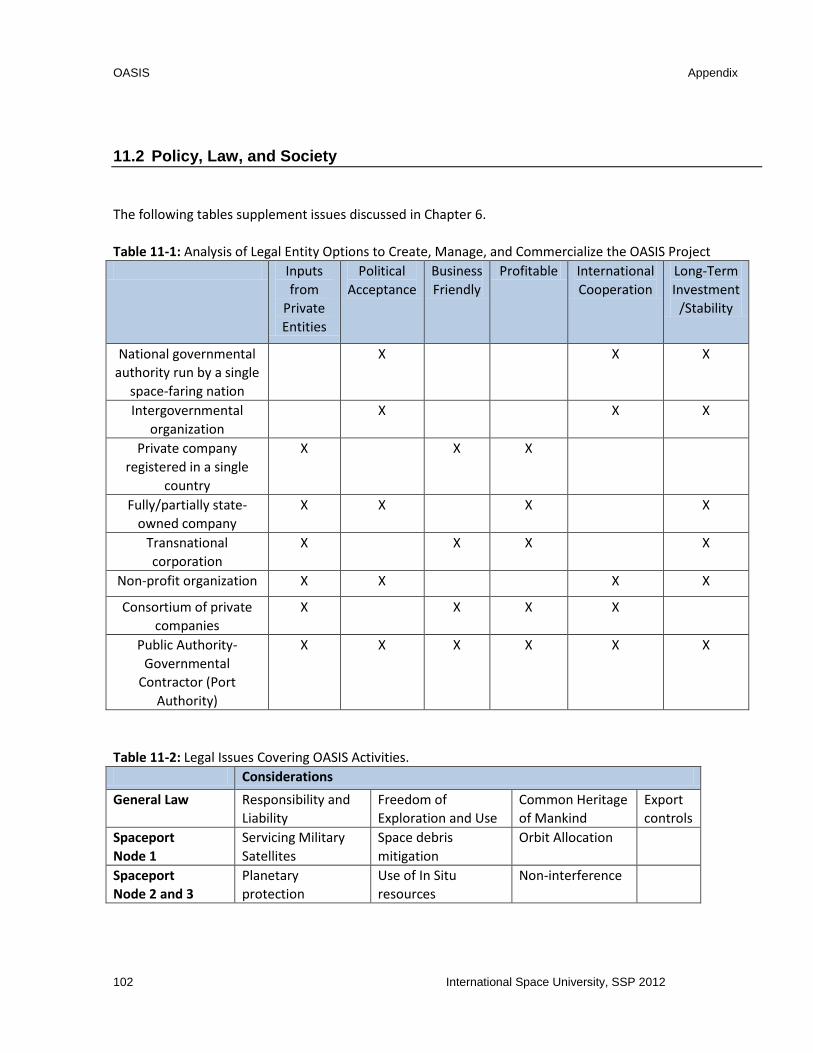
OASIS Appendix
102 International Space University, SSP 2012
11.2 Policy, Law, and Society
The following tables supplement issues discussed in Chapter 6.
Table 11-1: Analysis of Legal Entity Options to Create, Manage, and Commercialize the OASIS Project
Inputs
from
Private
Entities
Political
Acceptance
Business
Friendly
Profitable International
Cooperation
Long-Term
Investment
/Stability
National governmental
authority run by a single
space-faring nation
X X X
Intergovernmental
organization
X X X
Private company
registered in a single
country
X X X
Fully/partially state-
owned company
X X X X
Transnational
corporation
X X X X
Non-profit organization X X X X
Consortium of private
companies
X X X X
Public Authority-
Governmental
Contractor (Port
Authority)
X X X X X X
Table 11-2: Legal Issues Covering OASIS Activities.
Considerations
General Law Responsibility and
Liability
Freedom of
Exploration and Use
Common Heritage
of Mankind
Export
controls
Spaceport
Node 1
Servicing Military
Satellites
Space debris
mitigation
Orbit Allocation
Spaceport
Node 2 and 3
Planetary
protection
Use of In Situ
resources
Non-interference

OASIS Appendix
International Space University, SSP 2012 103
Figure 11-1: Diagram of the Model Structure
11.3 Tug
Based on our assumptions, the dry mass of the tug is 2.9 tons. Calculations shown below:
Component Mass(kg) Robotics 200 Communication system 30 Propulsion (includes aero-shell) 400 AOCS 50 Structure 600 Fuel cells 20 Tank 1600
Total for tug 2900
References: (Larson and Wertz, 1999)
The payload mass to transfer to GEO is 9 tons
The amount of propellant needed for a round trip from Spaceport Node 1 to GEO is 22.85tons.

OASIS Appendix
104 International Space University, SSP 2012
Total mass to transfer to GEO: Satellite (9) + dry tug (2.9) = 11.9 tons
Spaceport Node 1 to LEO: ∆v = 0.2, mp/mu=0.046347202
LEO to GEO: ∆v = 4.2, mp/mu=1.589358407
Using the rocket equation, the amount of propellant needed is Mass x mp/mu ratio where
The amount of propellant to transfer 11.9tons from Spaceport Node 1 to GEO is 19.4648 tons. From Spaceport Node 1 to LEO: 11.9 * 0.046347202 = 0.5515t
Propellant LEO to GEO: 11.9 x 1.589358407 = 18.9133t
Total amount from Spaceport Node 1 to GEO: 0.5515 + 18.9133 = 19.4648t
Total mass to transfer to LEO: tug =2.9t.
GEO to LEO: ∆v = 1.5 with aero-braking, mp/mu=0.404651642
LEO to Spaceport Node 1: ∆v = 0.2, mp/mu=0.046347202
The amount of propellant to transfer 2.9 tons from GEO to LEO is 1.3078 tons. From Spaceport GEO to LEO: 2.9 * 0. 404651642= 1.1734t
Propellant LEO to Spaceport Node 1: 2.9 x 0. 046347202= 0.1344t
Total amount from GEO to Spaceport Node 1: 1. 1734t + 0.1344t= 1.3078t
Total amount of propellant needed to transfer a 9t satellite to GEO and bring the tug back is:
19.4648t + 1.3078t = 20.7726t
Safety margin is 10%
Total amount of water needed to produce 22.85t of propellant is 30 tons.
Total amount of water needed is 22.85 (propellant) * 1.3 (electrolysis ratio) = 29.70t - > 30t (300kg safety)
11.4 Spaceport
Each tank has a dry mass of 1.5 tons.
The dry mass of one module is 7.8 tons
Table 11-3: Mass Budget for the Depot
Depot major components Mass (kg)
Tank, thermal protection and debris shielding 1500
AOCS 200
Electrolyzer, radiator and cryocooler 6300
Thin film amorphous silicon photovoltaic arrays 550
Communication systems and antennas 30
Total 8580

OASIS Appendix
International Space University, SSP 2012 105
200kW is required to produce 0.33 tons of propellant per day (Potter, 2001)
68.5 days is necessary to produce 22.85t of propellant; 22.85/0.333=68.5 days
The radiator area is 84m2
Using Heat balance equation and Stefan-Boltzmann equation [SMAD, p. 454]:
- Spaceport internal heat flux.
We assume a total internal heat flux of 66kW. The main heat sources are: electrolyzer, pre-cooler,
cryocooler systems.
radiator emittance, radiator coating material – Z93 white paint [SMAD, p. 436]
W/m2K4 – Stefan- Boltzmann constant
T=350K radiator temperature [SMAD, p. 428]
A – radiator area
The total surface area of the solar panels is 666m2 per module. Based on the current technology we estimate that we can produce 0.3Kw/m2.

SPACE STUDIES PROGRAM 2012INTERNATIONAL SPACE UNIVERSITY | FLORIDA INSTITUTE OF TECHNOLOGY | KENNEDY SPACE CENTER
ASIS
Operations
And Service
Infrastructure
for Space
Authors
Final Report
Melanie Clegg U.S.A.
Vincent Coache Canada
Tyler Dwyer Canada
Shady El Azab Belgium
Kristin Freeman U.S.A.
Shai Gerner Israel
Marc Gick Canada
Fei Guan China
Yuri Ishizu Japan
Sebastian Klaus Germany
Marc Labriet U.S.A.
Mikkel Ladegaard Denmark
Frederico Larangeira Portugal
Luliang Lou China
Zhuoyan Lu China
Qinglang Luo China
Nuno Loureiro Portugal
Julie Mason U.S.A.
Narasimha Murthy N. Narasimhulu India
Paul Nizenkov Germany
Duarte Sousa Portugal
Fredrik Persson Sweden
Udrivolf Pica Italy
Lucie Poulet France
Maxime Puteaux France
Dmitry Rachkin Russian Federation
Eirini Maria Sfantzikaki Greece
Yuan Si China
Chrishma Singh-Derewa U.S.A.
Rui Sousa Portugal
Suki Dauda Sule Nigeria
Anna Szwemin Poland
Graeme Taylor United Kingdom
Aliya Valiyff Australia


