Final Report – GreenFarm Energy UK Ltd Anaerobic Digestion Pre- Treatment system investigation Utilisation and incorporation of grass silage feedstocks into on-farm AD systems – Requirements for a pre-treatment system. Project code: OIN001 ISBN: [Add reference] Research date: 2012 Date: August 2013
Transcript
Final Report – GreenFarm Energy UK Ltd
Anaerobic Digestion Pre-
Treatment system investigation
Utilisation and incorporation of grass silage feedstocks into on-farm AD systems – Requirements for a pre-treatment system.
Project code: OIN001 ISBN: [Add reference] Research date: 2012 Date: August 2013
WRAP‟s vision is a world without waste, where resources are used sustainably. We work with businesses, individuals and communities to help them reap the benefits of reducing waste, developing sustainable products and using resources in an efficient way. Find out more at www.wrap.org.uk This report was commissioned and financed as part of WRAP‟s „Driving Innovation in AD‟ programme. The report remains entirely the responsibility of the author and WRAP accepts no liability for the contents of the report howsoever used. Publication of the report does not imply that WRAP endorses the views, data, opinions or other content contained herein and parties should not seek to rely on it without satisfying themselves of its accuracy.
Written by: Aaron Black South West College, Northern Ireland
Front cover photography: GreenFarm Energy UK Ltd / South West College demonstration AD plant, Omagh, Northern Ireland.
While we have tried to make sure this [plan] is accurate, we cannot accept responsibility or be held legally responsible for any loss or damage arising out of or in
connection with this information being inaccurate, incomplete or misleading. This material is copyrighted. You can copy it free of charge as long as the material is
accurate and not used in a misleading context. You must identify the source of the material and acknowledge our copyright. You must not use material to endorse or
suggest we have endorsed a commercial product or service. For more details please see our terms and conditions on our website at www.wrap.org.uk
Anaerobic Digestion Pre-Treatment system investigation 1
Executive summary
With anaerobic digestion becoming a widely recognised technology for the treatment of organic residues and the generation of renewable energy in the UK, increasing emphasis has been placed on the design of systems most suited to the feedstocks available locally. With a local agricultural industry based primarily on the production of grass silage for livestock, the potential of this feedstock for AD is now being realised. Local knowledge and past experience suggests however that the feeding and management of a grass silage based digester will present significant challenges if the feedstock is not prepared suitably before feeding to the digestion system. With the majority of currently available technology being based on designs for maize silage, this project has evaluated the potential cross over with this technology, the additional issues presented by grass silage and the possible engineering solutions. New and novel technology has been designed and evaluated for utilisation in the UK and Irish AD industries. This equipment will suitably process feedstocks through pre-treatment before being fed to digesters, this will ensure the impact on AD performance due to poorly prepared feedstocks are reduced. The system designed in this study will improve the overall ease of operation of the AD system when based on grass silage feedstocks.
Anaerobic Digestion Pre-Treatment system investigation 2
Contents
1.0 Introduction and background ....................................................................... 4
Anaerobic Digestion Pre-Treatment system investigation 3
Glossary
AD – Anaerobic Digestion DM – Dry Matter GFEUK – GreenFarm Energy UK Ltd. NI – Northern Ireland CHP – Combined Heat and Power FE – Further Education R&D – Research and Development MLA – Member of Local Assembly SWC – South West College DEL – Department for Employment and Learning ANSWER – Agricultural Need for Sustainable Willow Effluent Treatment PLC – Programmable Logic Controller VSD – Variable Speed Drive VFA – Volatile Fatty Acid
Acknowledgements We wish to acknowledge the valuable financial contribution made by WRAP to allow this investigation to take place. We also wish to acknowledge the valuable support and contributions made by the directors of GreenFarm Energy UK Ltd. and the South West College for their continued support for this developing area of renewable energy technology.
Anaerobic Digestion Pre-Treatment system investigation 4
1.0 Introduction and background
1.1 Company/consortium
GreenFarm Energy UK Ltd. This project has been undertaken on behalf of GreenFarm Energy UK Ltd. by South West College. GreenFarm Energy UK Ltd. (GFEUK) is a family owned business with interests in anaerobic digestion (AD), waste transport and renewable technologies. The company currently owns and operates a 40kWe on farm digestion plant in Northern Ireland (NI). The company has been conducting research associated with anaerobic digestion since 2005 in partnership with the South West College and the Institute of Technology Sligo. The company built the first of the new generation of on farm AD in Northern Ireland in 2008 incorporating a dual fuel biogas/biodiesel combined heat and power (CHP) system which is the first such installation in the UK and Ireland. GreenFarm Energy‟s focus is on the optimisation of small scale farm based AD systems which are suitable for the typical farm in the UK and Ireland. The optimal system is believed to be in the 100kW range. The company regularly travels to Germany and has recently observed a shift towards the 75kW farm scale digester with a number of processing steps included to allow small footprint systems to produce high outputs from low inputs. On behalf of South West College and the Institute of Technology sligo, GreenFarm Energy UK Ltd. has participated in and undertaken a wide range of research programs. Studies undertaken to date include organic matter pre-treatment, AD process optimisation, remote access and operation, seaweed biogas production, grass silage processing and biodiesel production. As such, the company actively engages with research and development (R&D) and allows experimental access to their digestion facility for college and university employees and students. As well as conducting applied research, GFEUK allow open access to their site for technical tours and demonstrations. This has seen Members of the Local Assembly (MLAs), Farmers Union representatives, council members, engineers, company directors, farmers and operatives all visiting the facility to learn how the technology operates and develop their understanding. Also hosted are school, college and university site visits for students studying topics such as engineering, energy, electrical, biological and environmental science. The directors provide guidance on technology and policy as well as public speaking to agricultural groups. South West College
South West College (SWC) has been involved in the installation, operation, demonstration, design, manufacture and optimisation of all the main renewable energy and sustainability technologies since 2003. SWC is the leading renewable and sustainable technologies further education college in Ireland and has received national and international recognition for its work in this area through numerous awards. The college has built and delivered a wide range of renewables installation curriculum and is the sole agent for City & Guilds Domestic Wind Turbine Installation training in the UK & Ireland. The college focuses heavily on the wind, biomass, AD and renewable transport fuels sectors. The college led the Northern Ireland FE sector through its Carbon Zero NI programme which aimed to deliver R&D services to local industry working in the areas of renewable and sustainable technologies. Since Nov. 2011, 120 R&D projects have been completed by this consortium. SWC is engaged with the energy industry
Anaerobic Digestion Pre-Treatment system investigation 5
and has at this stage built up a significant presence in the sector and is now seen as the most pro-active college in Northern Ireland in this area in terms of practical industrial support for R&D having delivered an extensive range and number of projects for business. The work of the SWC InnoTech Centre has seen the development of new technology (wind, biomass, waste, hydro, construction) and the experimental testing of new prototypes (biomass, AD, renewable fuels, wind). As a standalone knowledge provider, the centre has conducted 90 industry R&D projects in the areas of biomass production and utilisation, hydro systems, wind turbine design & manufacture, electrical control systems for renewable installations, AD system design, specification and installation and pyrolysis. The college has worked across Northern Ireland, Republic of Ireland, Europe (Austria, Germany, Denmark, Belgium and Italy) and the USA. Its work is local, national, international and always collaborative engaging with all key knowledge providers. The college activities in the area include the installation of biomass district heating systems (0.3, 1 and 1.3MW) and the creation of biomass supply chains, site tours of renewable energy installations (PV, heat pumps, biomass, AD, wind and waste), FE sector wide R&D and training projects, placing of graduates in international companies, development of new national sustainability education policy, publishing of educational resources in biomass, AD, construction and energy efficiency, training courses in all sustainable technologies, biomass, wind turbine emergency escape training (using a 30m tower), partnership with collaborative networks, development of international projects, delivery of sustainability conferences at national and international levels. 1.2 Introduction to the technology
Project aim In order to optimise our system and increase the number of generation hours per day, GFEUK and SWC have built a pre-treatment system which creates a pumpable blend of feedstocks for digesters. Laboratory trials with our partner college in the Republic of Ireland (Institute of Technology Sligo) have demonstrated a 20% increase in gas yields is possible when digesting the pre-treated feedstock this new piece of machinery produces. These results have been recently published at the IBBK Progress in Biogas conference at the University of Hohenheim Germany. We have designed and tested the pre-treatment technology and the product it produces which has produced exciting enhancements in gas yield. However we require an additional processing technology to transfer the processed material from the pre-treatment vessel to the digestion system and complete some additional processing to further enhance biogas yields, this is the key project aim. Using the newly designed technology we will use pre-treated material to produce an enhanced biogas yield. Pre-treatment technology to manage silage is of high potential to the Irish AD industry however it presents significant issues in its pumping and processing. The new transfer step designed here will allow us to pre-treat the material producing a pumpable feedstock. This reduction in particle size will both increase the rate of biological degradation and the gas yield. New technology aim The new piece of technology designed here combines our pre-treatment system with our digester through an additional processing phase to produce an optimal feedstock for our digester. The new specialist delivery system treats and allows for the delivery of high dry matter material into the digester without the complications of blocked pumps and pipes.
Anaerobic Digestion Pre-Treatment system investigation 6
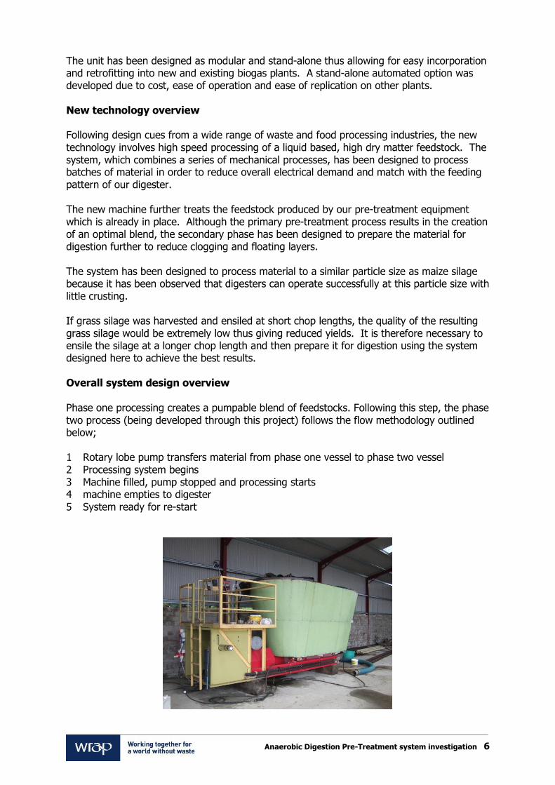
The unit has been designed as modular and stand-alone thus allowing for easy incorporation and retrofitting into new and existing biogas plants. A stand-alone automated option was developed due to cost, ease of operation and ease of replication on other plants. New technology overview Following design cues from a wide range of waste and food processing industries, the new technology involves high speed processing of a liquid based, high dry matter feedstock. The system, which combines a series of mechanical processes, has been designed to process batches of material in order to reduce overall electrical demand and match with the feeding pattern of our digester. The new machine further treats the feedstock produced by our pre-treatment equipment which is already in place. Although the primary pre-treatment process results in the creation of an optimal blend, the secondary phase has been designed to prepare the material for digestion further to reduce clogging and floating layers. The system has been designed to process material to a similar particle size as maize silage because it has been observed that digesters can operate successfully at this particle size with little crusting. If grass silage was harvested and ensiled at short chop lengths, the quality of the resulting grass silage would be extremely low thus giving reduced yields. It is therefore necessary to ensile the silage at a longer chop length and then prepare it for digestion using the system designed here to achieve the best results. Overall system design overview
Phase one processing creates a pumpable blend of feedstocks. Following this step, the phase two process (being developed through this project) follows the flow methodology outlined below; 1 Rotary lobe pump transfers material from phase one vessel to phase two vessel 2 Processing system begins 3 Machine filled, pump stopped and processing starts 4 machine empties to digester 5 System ready for re-start
Anaerobic Digestion Pre-Treatment system investigation 7
Phase 1 processing equipment already present on site. As this is an on-farm system, we have designed all components currently in use to have as low an operational cost as possible. The technology incorporated is easily recognisable as farm based and the tools required for repair and maintenance are standard to those already commonly available on farm. The system has been designed to have little requirement for maintenance with the removal/changing of parts being easily and safely achieved. The system has been designed with all necessary emergency stops. 1.3 Proposal (technology/concept) background
1.3.1 Where – origins of technology? The new technology developed through this projecthas drawn heavily on machinery carrying out similar processing functions in other industries:
Food processing
Silage harvesting
Chopping & pumping systems
Conventional AD equipment
Lawn mower technology
Industrial processing and cycle for batch treatments
By combining the best aspects of technology from each industry a suitable piece of equipment has been designed. 1.3.2 What – what has been achieved to date? To date our existing pre-treatment system has been built, tested and demonstrated to treat agricultural slurry and grass silage to increase the overall biogas outputs. The system has been presented at national and international biogas conferences and has been the subject of many scientific trials. To enhance the system already installed, through this project, we have designed a new technology to cater for an emerging biogas market. An additional high dry matter processing phase has been developed. Through the project we have achieved the following;
Optimal particle size
Mechanical designs have been considered drawing on Best Available Technology
Mechanical design of new system using 3D CAD
Specialist materials selected for manufacture
A stand-alone electrical system designed
Process phases identified for programming
Production/manufacture costs calculated
1.3.3 Why – Why this technology? The method of processing has been chosen as it is already used extensively in industries with a very similar principle to that being used here. Materials are effectively combined in an optimal blend for digestion. Materials have been chosen due to their availability, ease of maintenance and cost.
Anaerobic Digestion Pre-Treatment system investigation 8
We have reviewed numerous other pieces of AD processing technology and are of the opinion, following trials, that they are not suitable methods for primary pre-treatment processing of AD feedstocks with high dry matter. High dry matter feedstocks have been found to rapidly block systems resulting in increased overall energy consumption to complete the same volume of work. We are of the opinion that the system designed in this instance will allow both free movement of the feedstock (thus preventing blocking) and an effective level of processing. By combining various feedstocks, the overall energy consumption to produce the same processing action is greatly reduced in comparison with similar systems. By combining materials at this phase, a mix is created which is ideal for digester feeding. This mixture is easily combined into the digester contents and the rate of temperature transition of the material is increased as is the overall accessibility to and rate of biological degradation. In contrast, in digesters using solids feeders, solid masses of material can become stagnant within the digester unless high volumes of energy are input into the system to move the material and make it flow. By feeding a digester with the conventional plug flow model, the initial rate of biological degradation of the material can be very slow unless the solid material is immediately incorporated into the main digestate flow. Overall, the processes designed through this study will produce a feedstock which is suitable and ready for feeding to a digester. The material will be processed to create a material readily available to the micro flora within the digester for breakdown and rapid methane production. We predict that once taken to the demonstration phase, using this technology will allow for a reduction in digester residence times thus allowing for the design and application of smaller digesters processing greater volumes of materials and producing the gas yields of plants with much higher footprints. 1.3.4 Application of your technology into the UK AD industry now and into the future The technology developed in this project has the potential for both direct and immediate implementation into the AD industry in the UK and the Republic of Ireland. At present, there are 80 AD plants in Northern Ireland attempting to obtain planning permission, the majority of which plan to operate on grass silage. Our system has been designed as a result of this. The technology is of interest to AD installation companies locally and internationally as foreign companies attempt to make sales into the UK AD market. Our technology is directly suited to the needs of AD installers and operators as it has been designed for our own functioning AD plant. As plants are now being specified and built for grass silage, this technology is very much „of the moment‟. As a stand-alone system, it can be easily incorporated into any AD installer‟s current system layout resulting in a technology which is easily adopted by all potential installers. Although the system can be specified and installed at the construction phase, it has also been designed to be easily retrofitted into existing plants. The system has been designed based to recognised standards and uses new technology. The sophistication offered by VSDs and electronic sensing built into the system result in a modern energy efficient operation.
Anaerobic Digestion Pre-Treatment system investigation 9
2.0 Project Objectives
2.1 What did you set out to achieve from the feasibility study and what are your aims for the demonstration
The overall aim of the feasibility study was to investigate if a new system could be designed, cost estimated and appraised to prepare grass silage correctly for an AD system. We aimed to design a system which could be integrated successfully into our existing AD plant and technology as well as being suitable for integration into other installer‟s systems with ease. We aimed to investigate if a fully integrated or a standalone control system was the best option for ease of operation. We wished to appraise the currently available technology designed to complete a similar function and draw upon the best design aspects to develop outline plans for a new system suitable for the UK market. Within the AD industry, several plants have been experiencing issues with floating layers and excessive parasitic loads for processing feedstocks and mixing. Ultimately we aimed to design a piece of equipment to address these issues in the UK AD market we had identified. For demonstration, we will continue our already successful college technical demonstrations on-farm at the AD plant. The project has been attracting interest from AD technology suppliers locally and as such we plan to either develop or lease the technology with them. The plant continues to be demonstrated to a wide audience on a continuous basis. As well as hosting conferences and technical seminars through which the technology will be demonstrated, college students will be allowed full access to the site for both educational and practical purposes for the completion of dissertation research projects. As well as allowing student access, we will be continuing our R&D activities with both commercial and academic partners. Our plant is an open site, available for continual demonstration to a very wide range of interested parties.
2.2 How does the feasibility report and the proposed demonstration project meet the
desired outcomes of the „Driving Innovation‟ programme The technology developed here is in direct response to an identified gap in the technology currently available for the AD market in the UK. Digesters are experiencing difficulties using UK feedstocks with plants specifically experiencing floating layers and excessive mixing requirements to keep feedstocks such as grass silage in solution. As such we have developed a system which will optimise the biogas production from these feedstocks. Using this technology, the overall biogas system will be optimised by;
improved mixing efficiency
improved heat transfer and convection
improved digestate movement within the digester
reduction of floating layers and crust
improved biogas bubble formation and gas escape
increased feedstock surface area
reduced digester size
reduced retention times
Anaerobic Digestion Pre-Treatment system investigation 10
improved ease of land application
reduced pump maintenance
reduced unscheduled maintenance to pipes and valves
reduced energy cost for pumping
reduced volumes of un-mixed internal digester solids
reduced energy requirement for digestate removal from digesters
For small scale systems, the technology developed aims to reduce the cost and complexity of operation in the following ways;
increased gas yields from reduced inputs
reduced capital expenditure for digester purchase
increased levels of feeding automation
reduced maintenance and down time
simple push button operation (no computer input)
recognisable on-farm technology
reduced overall plant size
more stable feedstock resulting in a stabilised digestion process
reduced need for external consultants to “monitor and adjust” the system
reduced overall expenditure on system operation through homogenisation
3.0 State of technology 3.1 Development history of the technology, previous use, other sectors and laboratory
results For anaerobic digestion, incoming waste is commonly put through a pre-treatment process before being pumped into the digester. Primarily, pre-treatment systems are used to remove non-biodegradable materials such as grit, timber, metal or plastic (strings/pipe, packaging) which would wrap around pumps causing damage and reduced performance or block pipes, sensors and valves further downstream in the system. Pre-treatment systems are also primarily used to mechanically reduce or remove materials which would cause sedimentation within the digester system. Sedimentation can result in costly system shut downs causing lost revenue. Pre-treatment systems may also be designed to attempt to improve the biogas potential of the feedstock. By attempting to improve economic viability of low gas potential feedstock, the overall viability of the anaerobic digestion plant may be improved. Pre-treatment systems may also be designed to allow the addition of products such as chicken litter, farm yard manure or silages whilst reducing the level of sedimentation and crust formation through the use of the pre-treatment steps devised. During the pre-treatment phase, a small expenditure on energy input to process the feedstock correctly may result in a large reduction in the level of energy required for overall digester mixing by reducing the potential for sedimentation and crusting during digestion. This reduces the overall level of parasitic loading on the plant. Primarily, the system being designed here is concerned with a two-step pre-treatment process. The first phase involves the thermal and mechanical pre-treatment of solid and liquid feedstocks followed by the second phase being designed in this project. Currently pre-treatment steps occur through numerous types of systems with varying levels of complexity and cost.
Anaerobic Digestion Pre-Treatment system investigation 11
Stone trap Traditionally stone traps are integrated into effluent systems as small settling ponds which allow the velocity of the incoming slurry/manure to drop sufficiently so that stones and debris which is heavier than the surrounding manure will drop out of the solution. When they drop out, they will be captured in a holding tank which can be easily cleaned periodically.
Humes stone trap design for slurry systems[1]. In effect, the holding tank for the slurry before it is digested is acting as a large stone trap already in the system thus minimising the possibility of heavy materials coming into contact with the primary pump. It is possible however that stones and metals will enter into the system when solid feedstocks are introduced thus resulting in a requirement for some form of stone trap or settlement system to be installed between the pre-treatment phase and the maceration/pumping phase. This will be incorporated into the final design. Float trap Floating material may enter the system through a wide range of pathways and may relate to materials such as plastics, foam or wood. These items must be removed from the system at the earliest possible stage in order to prevent possible damage to pumps, pipes and valves. As well as causing damage to the system, these items must be removed to ensure hazardous floating layers in the form of un-degradable contaminants are not produced in the digester. If a floating layer like this was to occur, it would reduce biogas yields by taking up valuable digestion space and would block the pathways necessary for gas bubbles to burst on the surface. In order to remove floating items from the system and prevent damage to the digester, an additional floating layer removal step should be incorporated into the overall system. It is possible that technology from the waste water treatment industry is incorporated to auger off any floating surface layers into a skip/bin. This floating layer removal process should be incorporated into the same tank as the stone removal step. In order to remove floating items, a series of stainless steel augers slowly rotating on the surface of the tank could be utilised.
A shaft less screw conveyor would allow solid material to be removed from the system whilst allowing liquid digestible material to be retained for processing into the digester. Due to the feedstocks being used in this instance (grass silage and slurry), floating items (plastics, foam, wood) are not predicted to be an issue and as such this additional piece of equipment is not required on this system.
Anaerobic Digestion Pre-Treatment system investigation 12
Rotating screen Common in waste water treatment plants, rotating screens are used to remove stones and fines within the process water. Screens offer high levels of material separation with screen sizes being interchangeable depending on the material being collected. It is the case however that the material being processed in this application has a solid matter content which is desirable for the processing system, to screen/remove this fraction is not a suitable option. Although it is desirable to remove non-digestible components from the system, it is felt that a rotating screen would over remove desirable components also. Within digestion systems, the desirable fibre fraction has the potential to block screening systems and for this reason additional scrubbing apparatus is required. It is believed that this screening system is not suitable for the pre-treatment process being investigated here due to the complexity of the likely design and the potential difficulties of operation.
Flocculation Primarily used for removing nutrients from waste water treatment plants, flocculation involves the dosing of chemicals into a waste stream which cause target nutrients to bind together and form large groups which can then be screened or removed. It is also possible to flocculate the undesirable components from a biogas feed stream however it is not a suitable effective technology for this application. Sedimentation Sedimentation is primarily used to thicken the heavy components of the biogas feedstock so they can be removed from the overall system. This system applies the sedimentation process to remove solid materials from the process in a modification of the stone trap principal. In order for this process to work efficiently, each batch of treated material should be stored for two hours in a holding tank, this will allow sufficient time for any heavy non-biodegradable material to fall to the bottom of the tank and be held in sediment away from the drawing action of the process system. Periodically, sediment from this holding tank will have to be removed and land spread. This period is not known at present. Magnetic separation
It is possible to remove solid ferrous material using a magnetic belt separation system. It must be considered however how likely it is for metal material to enter the system before this item is specified and the suitability of this system to a liquid feed stream. Over-band, suspended or in-pipe separation is possible for ferrous materials. For the AD system, in-pipe designs are preferable if they are proven not to impede flow. It is the case that the stone
Anaerobic Digestion Pre-Treatment system investigation 13
trap within the system and the sedimentation equipment will capture the majority of heavy metal material passing through the system without the additional requirement for a magnetic system however a magnet could be applied to a ferrous surface to bind any passing metals through the system. In a food processing facility this may be required however in this system, due to the feedstocks being used this is not believed to be required.
Mainplant overband magnetic screen[4]. Eriez in pipe magnetic separator[5]. Feedstock homogenisation Incoming feedstock must also be homogenised through the use of pre-treatment and as such, a uniform material will be generated to allow for efficient digester operation and improved digestate quality. In other digestion systems, this homogenisation phase often involves shredders, screw cutters, milling and rotating drums with a horizontally mounted rotating cylinder, the rotation of which causes the mechanical breakdown of the input material thus reducing its particle size through collision and attrition. As outlined previously, screens and magnets may also be used within the system which will assist in meeting the requirements for uniform particle size and in the removal of metal/heavy non-biodegradable items from the feedstock. Feedstock homogenisation can also include the addition of water (or livestock slurry) to the incoming waste streams in order to achieve the correct DM% before being fed into the digester. This is necessary to maintain the correct solids content within the digester to prevent clogging and the formation of floating layers which will ultimately reduce the overall gas yields from the system. The ferocity of homoginisation is highly feedstock dependant. Conventional homogenisation systems utilise mixing and coarse grinding actions with augers and shaft based grinders. Key technology suppliers include Vogelsang and Borger.
Vogelsang EnergyJet solid material feeder[6] Vogelsang Quickmix system[7]
Anaerobic Digestion Pre-Treatment system investigation 14
Borger Multicrusher[8] Borger Multichopper[9]
Borger Powerfeed SSR[10] Vogelsang BioCut[11]
Chop lengths of grass silage harvested using a variety of commonly available methods.
Harvesting method Expected chop length
Round bales 20mm - 300mm
Single chop 20mm – 300mm
Double chop 20mm –200mm
Silage wagon 20mm – 300mm
Hay 100mm – 300mm
It is recommended by Silasil Energy that for biogas plants, grass silage is chopped to 15-30mm (http://www.schaumann-bioenergy.com/PDF/en/lit_biogasfibel_en_200611.pdf). At present, the majority of grass silage is not chopped to this length to reduce the number of instances of acidosis in livestock. Silage being harvested specifically for biogas should however be chopped to a much shorter length during the harvesting period. The chopping action will also have the effect of increasing the surface area of the feed stock and as such may improve its biogas production potential. Work conduced at the University of Cork (Sing, Nizamir, Korres & Murphy, 2001) has outlined the possible issues surrounding chop length and pre-treatment importance for feeding grass silage to anaerobic digesters to prevent the blocking of pipes.
Anaerobic Digestion Pre-Treatment system investigation 15
In work conducted by Torino University (Menardo, Airoldi & Balsari 2012), the lignin-cellulose bonds within numerous forage crops were broken by pre-treatment. These trials resulted in increased gas yields of up to 80% for straw crops when compared to the digestion of the original product without pre-treatment. Maize and rice pre-treatment did not directly demonstrate an increase in gas yield however the treatments did increase the rate of degradation within the digester and thus reduced the residence time. This results in a digester with smaller overall volume and faster throughput thus showing potential for lower set-up and operational costs. Also calculated in the Torino work was the electrical energy balance for a comparison of gas yields compared to electrical consumption to carry out the pre-treatment. For the majority of crops investigated this proved to be a positive relationship however maize and rice particle size reduction was only partially positive. The primary objectives of pre-treatment phases are to increase the surface area of the feedstock material, reduce the required retention times, increase the potential VS loading rates and reduce the potential for floating layers and blockages. The level of pre-treatment necessary will vary greatly depending on the source of the incoming feedstock. In cases where slurry alone is being treated from a single controlled source where contamination with plastics, grit and metal is avoided a simple stone trap may be all that is necessary. If treating wastes from a highly regulated source such as animal by-products, the level of pre-treatment and control over the system may be greatly increased. Through the treatments, cell destruction can occur, when this happens, the cell contents will be made available in the liquid fraction and as such their availability to the digester micro flora will be greatly improved thus increasing biogas production potential. A secondary issue arising is overall digester size and area of land required to produce sufficient volumes of grass silage for the system. If pre-treatment is utilised, both these parameters can be reduced thus reducing the overall impact of farm digesters and their financial viability improved. For this design, batch homogenisation using a bank of rotating knives has been selected operating on a timed system controlled by PLC. 4.0 Legislation The following regulations and legislation will apply to the development and installation of the new technology developed here.
Health & Safety at Work act The Health & Safety at work act is the primary piece of legislation covering occupational Health & Safety. For employees to be safe in the workplace, all equipment and conditions must be conducive to a safe working environment. If this equipment is to be manufactured and put into operation it must be fully compliant with this legislation. Provision and Use of Work Equipment Regulations 1998 In order to produce a piece of equipment which will allow those who own and operate it to meet the requirements under PUWER, the machine must be designed such that is is safe to use, maintain and inspect, provided with adequate instruction and training documents, correctly designed to offer safety controls, guards and stop devices. All PPE requirements for its safe operation must also be outlined.
Anaerobic Digestion Pre-Treatment system investigation 16
The Machinery Directive 2006/42/EC The Machinery Directive places requirements on manufacturers of machinery to ensure the products they manufacture and supply are safe to use. The Directive covers all industrial and domestic machinery with moving parts. To achieve full compliance with the directive, all the necessary associated directives must be achieved and complied with (for example, the Low Voltage directive). Often product certification will require external testing to comply with all necessary safety parameters. CE marking The equipment designed in this study will require CE marking if it is to be sold on the European market. By CE marking the product, it can be sold in European markets without reassessment of technical compliance. Health & Safety of machinery and equipment In order to CE mark the equipment and ensure it meets the requirements of the Machinery Directive, an operational Health and Safety audit must be undertaken. This audit will identify all operational hazards and outline methods through which these may be mitigated. As such, a full operators manual will be required. Pressure systems safety regulations 2000 & Pressure equipment Directive 97/23/EC The system designed here involves a vessel, piping, pressure accessories and assemblies as described within the pressure equipment regulations. Although it is an open vented system which should theoretically result in minimal pressure increases during operation, aspects of the system have the potential to increase in pressure due to blockages. It is a requirement on any person who manufactures equipment which falls within these regulations to ensure it complies with the necessary regulations. 5.0 Detailed technical appraisal of technology
5.1 Theory/process behind the technology & technical information Mechanical Design Essentially the system incorporates a fixed drum and maceration system.
Anaerobic Digestion Pre-Treatment system investigation 17
The drum design has been taken from a number of proven areas including silage harvesting technology, food processing and waste management. The drum shape has been selected in this instance to allow for optimal connections between the material being treated and the processing system. The design allows for the system to be filled and completely emptied before the next batch thus reducing the opportunity for batches to become mixed and the processing efficiency to drop. Horizontal mounting allows the machine to avoid the potential reduction in efficiency seen in vertically mounted machines caused by centrifugal and vortex effects. In order to feed material into the system, a 200mm section pipe has been specified. Although the connection lengths are short in this system, the fluid pressure drop due to the high dry matter is understood to be very high as found during previous onsite investigations. The larger 200mm section pipe has an overall reduced level of internal wall resistance thus allowing greater efficiencies when pumping material. The design has the benefit of a reduced number of protruding areas which may catch fibres in the material being treated which would otherwise clog the machine. This internal design has been optimised to produce free movement of material and the internal processing equipment. The equipment has been designed to minimise maintenance and repair cost. The machine has been specified to be made from stainless steel. This grade has been selected due to its good resistance to corrosion by acid environments and it‟s readily availability at an attainable price point. All barrel connections will be compression sealed with rubber. The system has been designed incorporating locations for sensors to feed into the electrical control panel for automation purposes. Overfill and run dry protection is incorporated. Electrical Design The overall electrical operation of the new machine has been designed to be stand alone. This direction has been taken to allow the machine developed to be operated outside of the central PLC system by a series of conventional push buttons. It is felt that this direction is more suitable for pre-treatment technology in the on-farm application as touch screen or mouse operated systems have been found to be difficult to utilise on-farm. A stand-alone system has also been designed to allow the machine to be easily specified and retrofitted to existing AD plants thus avoiding the complication of technical computer based interfaces between operating systems. Overall this system must integrate with the operation of the AD plant. For this reason, a number of key operational components have been transferred from AD plant control to pre-treatment system control. An operational flow chart has been developed to specify the programme to be followed by the equipment once directed to do so by the operator. This process will flow automatically depending on a number of feedback loops. The operation of the electrical system has been designed to be stopped in an emergency following the necessary electrical equipment safety requirements. The machine has been designed to be controlled by a stand-alone PLC. This piece of equipment will control the process as it operates automatically once initiated through a push
Anaerobic Digestion Pre-Treatment system investigation 18
button system. The PLC programme will follow the logic to carry out it‟s function. A central control panel will be constructed housing all control gear required for the system. The panel will house Variable Speed Drives (VSDs), relays, speed controllers, emergency stops and all other necessary electrical equipment. In order to optimise the processing speed of the system, a VSD has been specified for the motor driving the drum. Depending on the signal received, the machine will process the material in the normal way or will be stopped to protect against damage. Energy balance The machine has been designed with an electrical drive requirement of 54kW (not all operational at once) with an overall hourly operation cost of £1.14. The machine will process material in batch cycles taking 20 minutes to complete. In the laboratory, it is predicted that the installed machine, when combined with the existing pre-treatment vessel, will increase biogas yields by 20%. This figure is used following laboratory trials of pre-treated feedstocks at IT Sligo in 2008. It is the case however that conservative estimates when applied in an industrial situation will result in the machine increasing yields by 15% at best. The feedstock to the chopper system will have the following constituent components;
800kg cattle slurry
200kg grass silage
Following the process, hourly biogas yield is predicted to increase, the added value through this biogas increased is predicted to be £2.77 per m3 treated. As a result of the chopping process, the biogas yield from the standard feedstock is predicted to increase by 21m3 per hour Added value per m3 treated = £2.77 5.2 Operational parameters The new machine will operate on a wide range of feedstocks which contain a wide range of dry matter contents, it has also been designed to accommodate “heavy handed” users. The machine has been designed to;
Connect to, and integrate into all existing AD plant equipment
Consume less energy than its beneficial effect additionally produces
Operate on material up to 15% dry matter
Operate on material from 5-75 oC
Operate in a batch process
Operate in moderate acidic/alkaline environments (pH 3.5 – pH9)
Operate in an external environment
Operate automatically following initial user manual input
5.3 Comparison with „business as usual‟
With ours and other AD plants hoping to operate on locally available feedstocks, a wide range of issues are predicted to be encountered if a business as usual approach is adopted. Feeding high DM feedstocks has the potential to result in a requirement to regularly unblock
Anaerobic Digestion Pre-Treatment system investigation 19
pipes, pumps and valves. Long fibres will wrap around these items. As well as creating issues with pumping, un-processed material will float on the surface of digesters due to the internal heat, movements of gas and mixing. This requires elevated energy inputs for mixing in order to keep the material in solution and available for digestion. Unless a new piece of equipment is designed and developed for the high dry matter based AD industry, there is the potential for digestion projects to fail due to the issues outlined above. This failure will result in negative coverage for the digestion industry, poor public perception of the technology and a negative economic outlook for the owner/operators. Digesters being sold in the UK have been designed in mainland Europe to operate on feedstocks not available locally. Digesters sold using calculations of gas yield from laboratory reports often will not achieve the same level of payback as predicted due to the factors of crusting/floating layers and blockages as well as the increased electrical energy requirement for mixing the digester. For our AD plant, following a business as usual option results in the continued operation on cattle slurry only. The additional processing step designed here will not be manufactured/tested/optimised or demonstrated. The knowledge behind it‟s development will remain within the FE R&D department, and the technical knowledge will not be transferred to the industry resulting in sub-optimal operation of multimillion pound digesters. The new machine designed here will not be combined with our current pre-treatment system resulting in it remaining dormant and un-connected to the AD plant. If the business as usual option is followed, new currently un-available technology will not be brought to the market. The AD industry in the UK will be constrained due to difficulties utilising readily available feedstocks and the rate of development of on-farm digesters will remain stagnant. The business as usual option encourages operators to feed feedstocks into AD plants which are not processed correctly to extract the optimum levels of energy. Ultimately, this results in gross inefficiencies in the digestion process with elongated retention times, oversized digesters, elevated construction costs, high mixing energy inputs, operational difficulties and elongated payback periods. By incorporating the newly designed system, the digestion process in the UK can be significantly progressed to become more viable and fit for purpose. 5.4 Range The system can also be used for a wide range of other AD feedstocks to ensure the maximum surface area is available for biological breakdown. A wide range of materials can be catered for. Materials which may also be processed through this machine include;
Sandwiches
Chocolate
Bread
Vegetables
Meat processing waste (without bones)
Cereals
Cereal silage
Maize silage
Anaerobic Digestion Pre-Treatment system investigation 20
Green waste (not including wood)
Although a wide range of additional materials can be catered for, screening is required to protect the machine from coming into contact with an un-intended solid object. Although the machine is robust, it is not designed as a piece of grinding equipment. 5.5 Life cycle of technology / life cycle of equipment The machine has been designed using commonly available materials – stainless steel, steel, copper and magnesium. As such, these materials are readily recycled when the end of their serviceable life is reached. The machine is fully serviceable and recyclable. Wearing parts are designed using conventional hardened steel, when the end of life is reached, these can be provided for recycling and replaced with new items. Other wearing/degradable items such as motors are designed to be re-windable and as such, there is the possibility for these motors to remain with the machine for life. Overall, constructed from stainless steel, the machine is expected to have a long service life (over 15 years). As with any piece of heavy industrial equipment, wearing parts will require changing periodically. The period over which the blades have a serviceable life will depend greatly on the materials being processed. The standard blade life is expected to be 1.5 years with periodic sharpening during this time until the effective edge between blade and cutting surface is reduced and a suitable particle size is no longer produced. Over its life time, the machine will have a more beneficial impact on reducing greenhouse gases than it requires for its operation or produces during its manufacture due to the increase in biogas yields it is predicted to produce (compared to a plant not using this technology) which, in turn, will be used for the generation of renewable power. 5.5.1 Commissioning / decommissioning In order to commission the machine, the design drawings will be provided to local engineering companies for laser cutting of the stainless steel components. Specialist companies have been contacted for quotations for steel and stainless steel components at this time with lead in times of 1 week. Steel components will be combined and welded through sub-contract with one of the numerous specialist stainless steel fabricators in our local area. This phase will see the system manufactured to the spec of the engineering drawings. Electrical components for the system have been specified and priced. As with the steel components, this work will be sub-contracted to a specialist control panel builder in the local area (of which there are many). Again, the panel will be built to the strict design specifications developed through this project to ensure correct operation of the new equipment. The programming of the PLC will be carried out in–house to allow for the optimisation of the system and the setting up of operational parameters with reduced cost. When manufactured, the system will be installed by and commissioned through a prescribed series of tests to ensure safe and optimal operation. Decommissioning of the equipment will be a relatively simple process. The mechanical and electrical components will be de-coupled. The mechanical components will be dismantled and sent for recycling using conventional waste carriers. The electrical aspect will be dismantled and transferred to specialist WEEE recyclers. All aspects of this machine can be broken down and re-used through recycling.
Anaerobic Digestion Pre-Treatment system investigation 21
5.6 Risk Analysis
Risk No. Risk Likelihood of happening
Potential impact level
Mitigation
1 Project does not take place
Low High Seek WRAP funding, seek additional external funding
2 Manufacturing difficulties
Low Med Alternative designs drawn up
3 Incorrect manufacture
Low Low Modification/corrective measures taken
4 Electrical design incorrect
Low Low Modifications in house to correct design
5 Machine incompatible with existing system
Low Low Re-design and modifications to both sides of system
6 Machine unfit for purpose
Low High Re-design and continuation of R&D
7 Machine not processing to acceptable level of particle size
Low Med Modification of blades, modification of electrical settings
8 Similar machine already on market
Low Low Seek technology patent
9 Machine fails during operation
Low High Cause of failure investigated, replace/re-design
10 Damage to machine through misuse
Low High Operators trained on machine prior to use & operational manual
11 Operational safety issue
Med High Emergency stops in place to end processing and meet HAZOP requirements
12 CE marking not achievable
Low High Seek support from QUB & InvestNI
13 Machine fails to produce predicted benefits
Low Med Modification and R&D on system
14 Electrical shock Low Med System designed to current standards
15 Personal harm through mechanical contacts
Low High System designed by engineers as safe to operate. Warning symbols, gurads and interlocks in all required areas
16 System produces noxious gases
Med Med Built in ventilation pipework, system open to air
Anaerobic Digestion Pre-Treatment system investigation 22
17 Pump fails to stop
Low Low System overflows to bulk tank
18 Valves fail to close
Low Low System overflows, high level not reached
19 High levels of ware
Low Low Alternative materials iinvestigated to reduce rats of ware
6.0 Economic / Cost Benefit Analysis 6.1 Appraisal of: 6.1.1 Cost to industry/facilities including capex and opex
Equipment Item Cost + Vat (£)
TOTAL Manufacture cost £21,861
TOTAL Operational cost per hour £1.14
6.1.2 Financial benefits Operation of this system will have the overall benefit of increasing biogas yields. As calculated previously, we expect biogas yields to rise by 15% using this new equipment. The added value provided by the machine equates to £2.77 per m3 of feedstock treated of which £0.38 is expected to be used in electricity to complete the cycle. As a result, each m3 of feedstock will increase in value by £2.39. Annual repairs and maintenance have been taken at 5% of initial cost.
Anaerobic Digestion Pre-Treatment system investigation 23
Other than the associated improvements in overall income, the operation of this system will result in reduced energy for mixing requirements. A 10% saving in mixing energy requirement is predicted. Reduction in cost due to lower levels of lost time to clear pumps and pipes is difficult to calculate however it is estimated that approximately 100 hours per year is spent carrying out these operations. A 40% reduction is predicted. 6.2 Comparative Cost Benefit Analysis versus „business as usual‟ Business as usual equals no improvements in overall income, however when operating with the new equipment, a 3 year payback for the new capital equipment investment is predicted. 7.0 Overall Environmental Impacts Overall, the project and new piece of equipment contributes positively to the environmental credentials of AD systems and the production of renewable energy from organic material. By improving energy production rates, increased outputs are produced resulting in greater levels of extracted energy from the feedstocks used. As a result, the CO2 reduction credentials of bio-derived renewable power are improved by extracting more from less. By homogenising the mixture fully, a more digestible feedstock is produced, this new mix results in improved efficiencies within the parasitic loads of the AD plant. Reducing parasitic loads results in more of the renewable energy generated being provided to the grid opposed to being solely used on site for the “production” of renewable energy. This increased grid input offsets fossil fuel derived energy already on the grid more effectively and to a greater extent than if the new technology was not used. A more homogenised feedstock results in a more homogenous digestate. As a result of this, land application is improved and reduced power input is required for the mixing of the digestate store. As a result of the above environmental benefits, the system improves the carbon balance and production/use ratios seen when growing an energy crop for digestion as more biogas will be extracted from the same volume of crop resulting in increased levels of renewable energy production.
Anaerobic Digestion Pre-Treatment system investigation 24
Phase 2 Demonstration
1.0 Methodology for demonstration The demonstration phase will involve the integration of the pre-treatment equipment developed in this project into a working AD plant. The equipment will be combined with the existing plant and its control and automation will be programmed to allow full integration and operation. By demonstrating and monitoring the equipment in this way, clear and reliable information can be gathered for dissemination. This will allow potential future purchasers of the equipment to make their own economic assessment. To deliver the demonstration phase of the programme the project team will come together and draw upon its combined strengths in design, manufacture, installation, operation, optimisation and technology transfer. The current mechanical and electrical drawings for the system are finalised and ready for manufacture. Outline costs have been obtained for the mechanical and electrical components for the manufacture of the machine. In order to take the machine to manufacture, SWC will, through its procurement and finance department, procure all necessary system components through its standardised and externally audited ordering and purchasing procedures. Potential sub-contractors for the supply of goods have been sourced during the Phase 1 project. Build of the project will be sub-contracted. SWC will, through its audited purchasing arrangements, procure the necessary equipment components for the build. These will be supplied, accompanied with the manufacturing specification, to the successful candidate of a procurement exercise for the mechanical and electrical builds. The procurement of these services will follow the N.I. executive public procurement guidelines and thresholds. On site construction of the machine will be completed by M&E contractors to combine the mechanical and electrical components into a functional piece of demonstration equipment. As we are in partnership (SWC & GreenFarm Energy UK Ltd.) we already have a demonstration site secured with a fully functioning grid connected AD plant. Therefore, there are no issues with site availability or selection to be managed. A memorandum of understanding is in place between the partners. In the first instance, GreenFarm Energy UK Ltd. will be able to use the technology on their AD plant. A licensing agreement will be created between SWC and GFEUK if they wish to take the technology to market. If GFEUK do not wish to commercially exploit the technology developed through SWC‟s IP, other commercial licensees will be sought from the UK and Irish AD markets and within Europe. The operation, monitoring and optimisation of the new technology will be undertaken by SWC. The equipment will be subject to scientifically based trials to determine it‟s effective action and overall improvements in biogas yield through the processing phase. Laboratory trials will be conducted to determine on the bench, if the equipment is capable of processing a range of further feedstocks. Through data produced from biogas yield measurement and quality sensing, the improvement in biogas plant economics will be quantified. As well as monitoring and reporting on the effectiveness of the machine operation, the cost of operation will be monitored and reconciled against the benefits derived for evaluation purposes. As such, electrical demand, maintenance and any further expenditure on machine development will be investigated and reported against.
Anaerobic Digestion Pre-Treatment system investigation 25
Data will be logged automatically where possible and manually where not on a daily basis. This will create a solid steam of information to backup any future claims made concerning the benefits of the equipment. For demonstration, we will continue our already successful college technical demonstrations on-farm at the AD plant. As stated previously, the project has been attracting interest from AD technology suppliers locally and as such we plan to either develop the project in partnership or lease the IP for the technology to them. The plant continues to be demonstrated to a wide audience on a continuous basis. Recent visitors include a group of 15 cross border business men investigating renewable technologies. As well as hosting conferences and technical seminars through which the technology will be demonstrated, college students will be allowed full access to the site for both educational and practical purposes for the completion of dissertation research projects. As well as allowing student access, we will be continuing our R&D activities with both commercial and academic partners. Our plant is an open site, available for continual demonstration to a very wide range of interested parties. Having a high throughput of visitors to the site enables us to capture important personal monitoring and evaluation data. At present, all attendees to the site are required to complete a monitoring and evaluation report concerning the quality of their visit. This process will be continued with an additional section concerning the pre-treatment technology developed in this project. Attendees will be asked to appraise the technology and suggest modifications of improvements thus helping us draw upon the combined experience of those professionals who visit our site regularly and assisting in the evaluation process. 2.0 Project Timescale
The project will commence mid August 2012 and will follow the project time scale and plan below. The project will be financed through one of three options including partial WRAP funding;
Job Date
Source finance 15th August 2012 – 28th September 2012
Finalise system design 1st September 2012 – 28th September 2012
Conduct risk assessment 1st October 2012 – 19th October 2012
Conduct outline H&S check on proposed equipment
22nd October 2012 – 5th November 2012
Conduct CE and Machinery Directive audit on new machine
5th November 2012 – 7th December 2012
Tender of supply of electrical equipment Tender for supply of mechanical equipment
10th December 2012 – 21st December 2012
Tender for build of mechanical equipment Tender for build of electrical equipment Tender for M&E installation
14th January 2013 – 31st January 2013
Manufacture of electrical and mechanical components and delivery to site
4th February 2013 – 1st March 2013
Installation 4th March 2013 – 8th March 2013
Commissioning & Operation 11th March 2013 – 5th April 2013
Monitoring and optimisation Demonstration and evaluation
8th April 2013 onwards
Anaerobic Digestion Pre-Treatment system investigation 26
3.0 Cost breakdown
Equipment cost
Equipment Item Cost + VAT (£)
TOTAL Manufacture Cost £21,861
TOTAL Labour £60,000
Total cost for machine and project delivery (materials & labour) - £86,233 inc VAT 4.0 Evaluation and monitoring for WRAP reporting As with all projects completed by South West College, strict monitoring and reporting procedures will be put in place and followed to agreed timeframes. Information for use in project evaluation will be gathered from the following sources;
Potential end users to whom machine will be demonstrated
Engineers and installation companies
Operational data from the machine
Outputs from the biogas plant following commissioning
Changes in overall plant income
Data from laboratory research conducted
This data will be collected and compiled on a monthly basis during the operational/ demonstration phase of the project and provided to WRAP bi-monthly in the format of a project report. A list of visitors to the site will be compiled, this will be accompanied by their contact details and a client evaluation form detailing their company name, size, location, area of work, the benefit derived from the demonstration activity and their recommendations for improvements. The financial viability of the project will be assessed after 6 months of operation with energy consumption and increased energy production calculated against the cost of each component to evaluate the overall financial benefits from machine operation. Overall energy consumption of the centralised mixing system will be accumulated before and during the demonstration period. Again, this data will be used when calculating the overall financial viability and payback periods for the machine. Post project, a full programme evaluation will be conducted to assess the benefits derived from WRAP funding by our College Quality management team following the IQ:RS format. A report to WRAP will include all of the above data and information.
Anaerobic Digestion Pre-Treatment system investigation 27
5.0 Health and Safety
Risk No. Risk Likelihood of happening
Potential impact level
Mitigation
1 Project does not take place
Low High Seek WRAP funding, seek additional external funding
2 Manufacturing difficulties
Low Med Alternative designs drawn up
3 Incorrect manufacture
Low Low Modification/corrective measures taken
4 Electrical design incorrect
Low Low Modifications in house to correct design
5 Machine incompatible with existing system
Low Low Re-design and modifications to both sides of system
6 Machine unfit for purpose
Low High Re-design and continuation of R&D
7 Machine not processing to acceptable level of particle size
Low Med Modification of blades, modification of electrical settings
8 Similar machine already on market
Low Low Seek technology patent
9 CE marking not achievable
Low High Seek support from QUB & InvestNI
10 Machine fails to produce predicted benefits
Low Med Modification and R&D on system
11 High levels of ware
Low Low Replacement blades designed from low cost steel
No. Health & Safety Likelihood of happening
Potential impact level
Mitigation
1 Machine fails during operation
Low High Cause of failure investigated, replace/re-design
2 Damage to machine
Low High Operators trained on machine prior to use
Anaerobic Digestion Pre-Treatment system investigation 28
No. Health & Safety Likelihood of happening
Potential impact level
Mitigation
through misuse & operational manual
3 Operational safety issue
Med High Emergency stops in place to end processing
4 Electrical shock Low Med System designed to current standards
5 Personal harm through mechanical contacts
Low High System designed by engineers as safe to operate. Warning symbols in vital areas
6 System produces noxious gases
Med Med Built in ventilation pipework, system open to air
7 Pump fails to stop
Low Low System overflows to bulk tank
8 Valves fail to close
Low Low System overflows, high level not reached
9 Blade detaches Med Med Motor load sensing, steel design to contain loose blades
6.0 Conclusion Overall we believe that Phase 2 of the programme represents value for money for WRAP and will assist in achieving the objectives of the Driving Innovation programme through optimising the AD process on both large and small scale plants, reducing operational complications and creating a new, currently un-available piece of equipment for the worldwide AD market manufactured in the UK. We believe the project time scales are realistic and by using the combined skills of our project team and others a strong project is deliverable. In terms of final demonstration, our site and technology is openly available to the AD industry. We have numerous contacts with AD installers and are well known for our work in this area. Demonstration on this site provides WRAP with the optimal opportunity for high profile recognition of funding coupled with successful new technology designed to meet the needs of this developing industry.
Anaerobic Digestion Pre-Treatment system investigation 29